
Jaguar XK/XKR Hydraulic Convertible Top Upgrade Instructions
Background Information:
This upgrade kit is designed for the Jaguar XK8/XKR model years 1996-2005. The
automatic convertible top in these model years is operated by a hydraulic system
manufactured for Jaguar by the Power Packer company. Power Packer is the primary
designer and manufacturer of convertible top systems that are also used by Mercedes and
BMW, plus many others. This system has suffered from a variety of premature failures.
This kit is designed to overcome flaws in the design of the Power Packer roof system and
improve reliability.
The failures, in approximate order of severity, have been the latch hoses, where they
fasten to the latch cylinder, the latch cylinder seals, the lift cylinder seals (located behind
the rear jump seat on both sides), and sporadically hoses in random locations.
The observed failures have been in majority related to high operating temperatures in the
latch area. Hydraulic components are rated by maximum operating pressure and
temperature. These two parameters interact such that a hose with higher temperature
rating will have lower pressure rating at that temperature and visa versa. The operating
temperature in the Jaguar is beyond our control but this upgrade kit is able to reduce
operating pressure by over 30% without affecting operation. This large pressure
reduction therefore increases the operating temperature range of the system. The relative
effect amounts to about 600 pounds of force that no longer must be contained by the hose
and seals.
Model years up to about 2001 used Nylaflow hose manufactured by Parker. This hose
was particularly unreliable. Later models have Polyflex hose (also manufactured by
Parker) installed. Polyflex hose has performed better but still has an unacceptable failure
rate in this system. Both of these hoses are custom for Power Packer and not
commercially available. The name of the hose is clearly printed on the hose. Also
printed on the hose is a date code in the form “1-Q-03” which in this case is the first
quarter of 2003. This date can be matched to the model year and other hoses in the
system to diagnose what has been done to the hydraulic system in the past. The
installation of hoses of different type and/or date code is an indication of prior
replacement and subsequent years of service.
Failures in the latch area are obvious as the driver can readily see the effects of the leak.
Failures of the lift cylinders are less obvious because the escaping oil drains out of the
bottom the car with no obvious symptoms beyond a small wet spot in front of one of the
rear wheels. If the reservoir level is persistently going down and requires periodic
attention, then the cause is probably a leaking lift cylinder. The leak occurs in the seals
that ride on the shaft as it goes in and out to raise and lower the top. A quantity of oil is
lost during each roof operation.
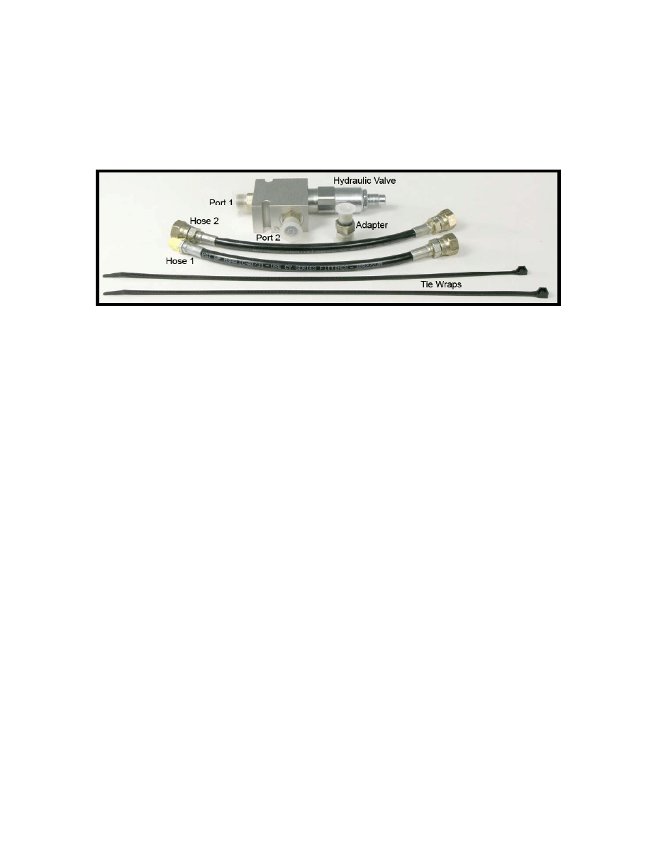
Jaguar XK Hydraulic Upgrade Kit Contents:
• 1 - custom hydraulic valve.
• 1 - 10 inch hose assembly (Hose 2) with female fittings both ends.
• 1 - 10 inch hose assembly (Hose 1) with female fitting and male fitting.
• 1 - hose Adapter.
• 2 - plastic Tie Wraps.
Figure 1 – Kit Part Identification
Tools Required:
T30 bit with right angle socket driver.
13mm socket.
11/16, 7/16, 5/8 Open End Wrenches
Pan or paint roller tray to catch hydraulic oil drips
Installation Instructions:
Make sure that the top system is working properly before installing this upgrade.
Installing the upgrade in a malfunctioning system will only complicate diagnosis of the
problem. Refer to Figure 1 to assist with part identification.
The fittings in this kit have either O-ring seals or Teflon Tape. Tighten to the point that
the fitting is snug but don’t overdo. Excessive torque risks damage to the O-ring or the
threads. When tightening the O-ring parts you will feel a point where the O-ring is fully
compressed and that is the place to stop. It is especially important to not damage the
pump assembly.
1. Remove the hydraulic pump assembly. The pump is located in the trunk, behind
the fascia that covers the stereo and navigation equipment. There are different
configurations for MY 1996-1999 and 2000 on. This procedure refers to the
MY2000+ configuration that has the taller electronics rack that places the pump
up under the fender. The earlier MY’s have the shorter rack and a different
arrangement for the fascia.
2. Pull the fascia out and fold it flat against the floor of the trunk compartment. Put
the catch pan on top of the folded fascia to hold the pump assembly during
installation.
a. Use the T30 bit with a ¼ drive socket (or right angle T30 if available) to
remove the two screws that hold the pump in place.
b. Make note of the hydraulic oil level in the tank. It should be between the
two lines on the tank. If not you will need to top off before reinstalling.
c. Carefully unplug the two wire harness connections to the pump motor and
solenoids. Do not pull on the wires when disconnecting as this can break
the connectors. The solenoid connector has a release latch that must be
pressed to remove. Note that early cars must be unplugged at the
solenoids while later cars (2000+) have one connector at the rear of the
electronics rack. The motor connector should be gently wiggled while
holding the plastic shell to separate the two parts.
d. Slide the pump assembly forward as far as possible and then rotate the
tank end toward the trunk compartment. Gently work the pump out, tank
end first, through the opening in front of the electronics rack and put it in
the spill tray.
3. Turn the manual valve (device on inboard side of the pump with the T handle in
Figure 2) counter clockwise slightly to allow any residual pressure in the system
to drain back into the tank. It is only necessary to crack this valve. Then turn the
valve back to the full clockwise position.
4. Roll the pump assembly on its side with the manual handle up to prevent oil from
leaking out due to gravity.
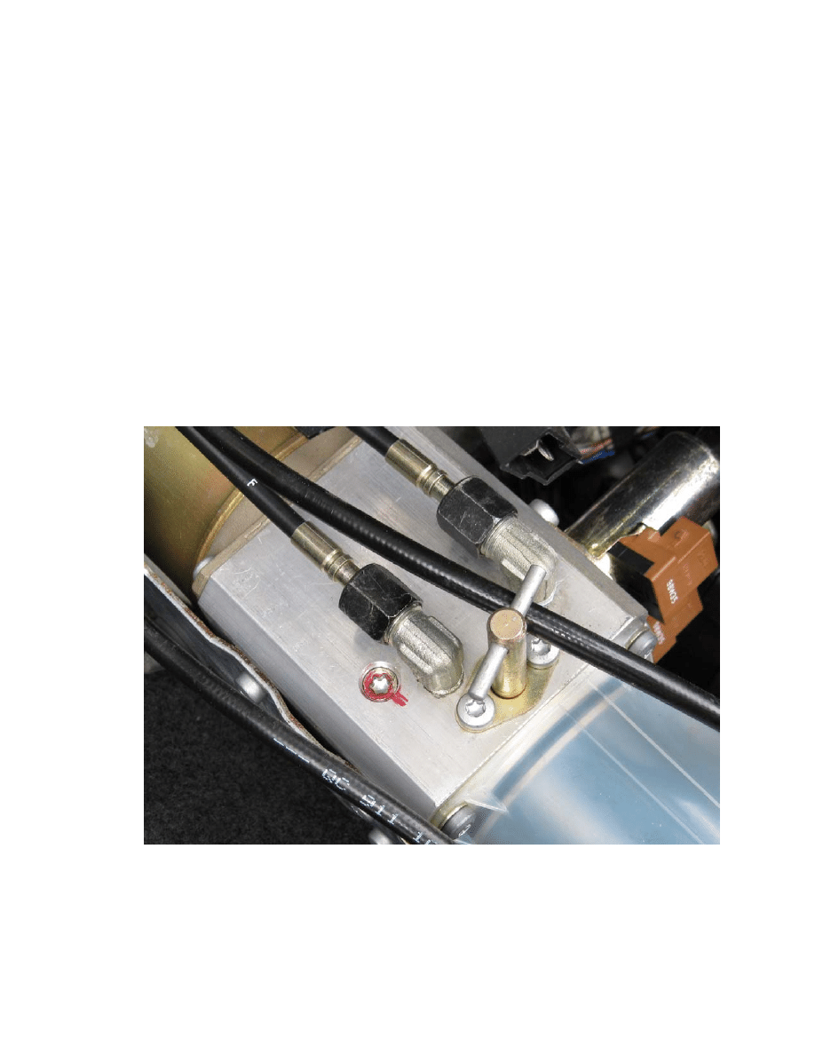
5. Use the T30 bit to remove the plug that is located below the lowest hose fitting.
This is the red item in Figure 2. On some pump assemblies it might be necessary
to twist the adjacent elbow for the latch hose out of the way.
Figure 2 – PORT 1
6. Install the male fitting on Hose 1 (see picture) into the hole where the plug was
removed. Use the 7/16 wrench to tighten.
7. Fasten the other end of this hose to Port 1 on the valve included in the kit. Use
the 11/16 wrench to tighten the fitting.
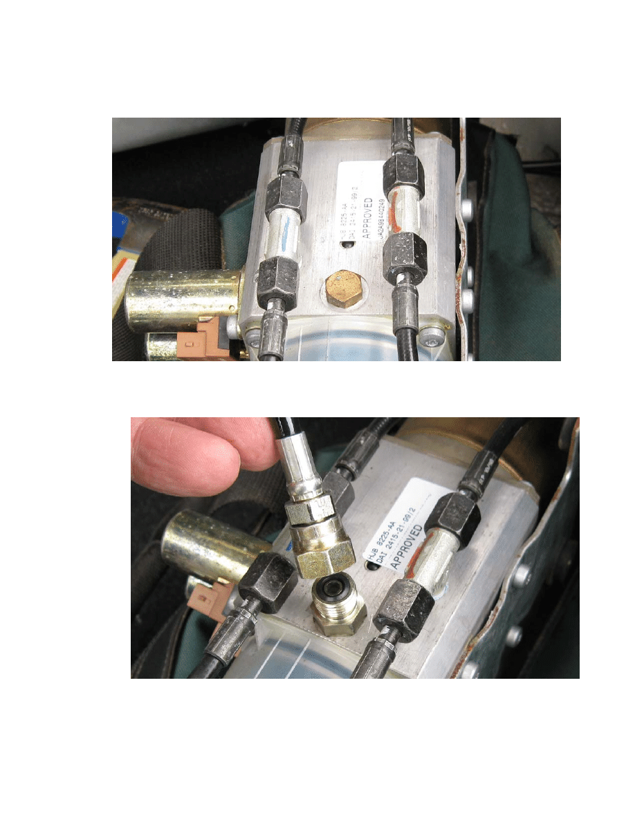
8. Position the pump so the opposite side is up as in Figure 3. Use the 13mm socket
wrench to remove the brass plug that is in the metal body near the tank. Use
caution as the tank can empty through this port.
Figure 3 – Port 2
9. Install the small end of the included Adapter fitting into this hole. Use the 5/8
wrench to tighten the fitting. See Figure 4.
10. Attach one end of Hose 2 to the Adapter and tighten using the 11/16 wrench.
Figure 4 – Port 2 Adapter and Hose 2
11. Position the Hydraulic Valve on the top side of the pump motor with the pointed
end toward the front of the car and fasten the other end of Hose 2 to Valve Port 2
and tighten with the 11/16 wrench. Refer to Figure 5.
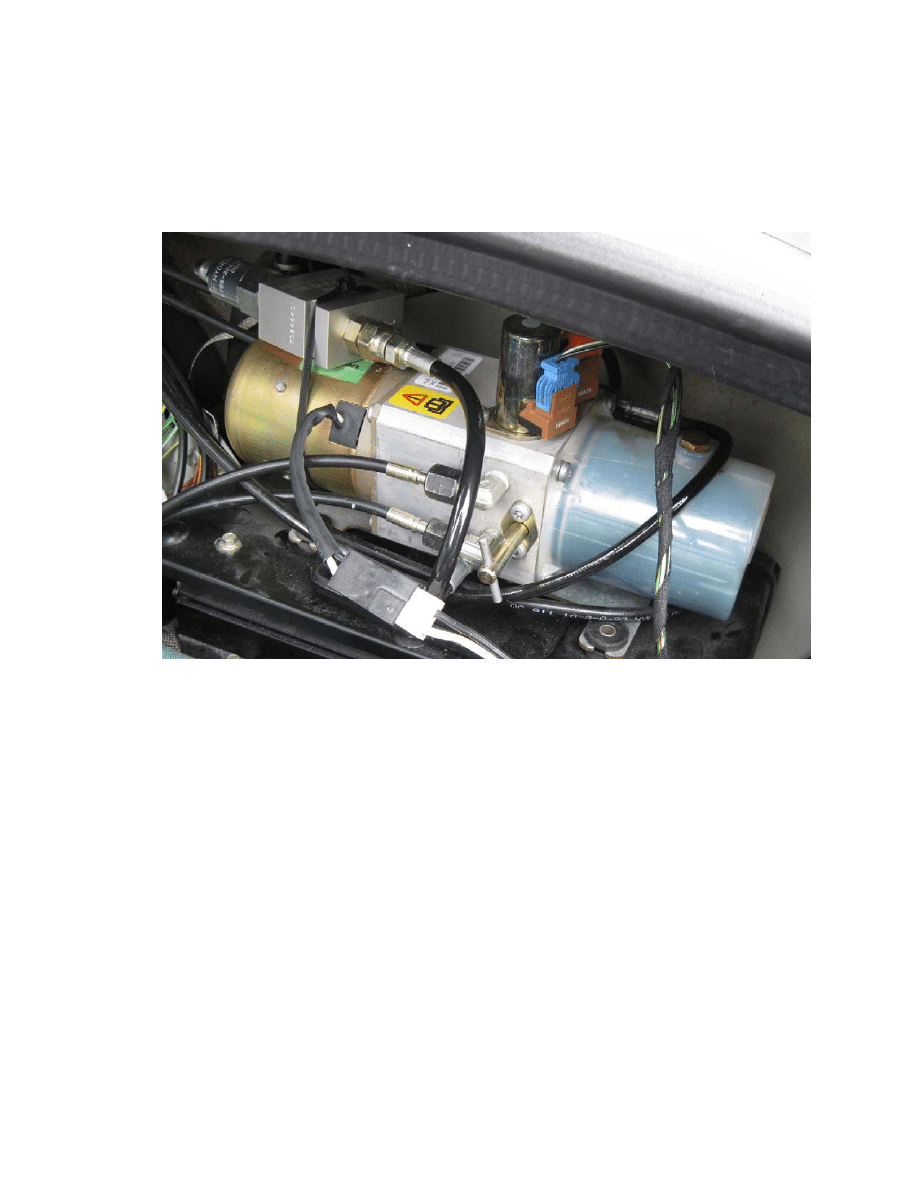
12. Adjust the position of the Valve and hoses to be on top of the motor with the
pointed end toward the front of the car. Thread the included wire ties under the
hoses and around the motor body and the valve. One tie can pass through the two
recessed spots in the Valve Body. The second can go over the recess at the
junction of the Valve and the rectangular Valve Body. Tighten the ties to hold the
valve in place. Do not pinch hoses under the tie.
Figure 5 – Pump and kit installed
13. Top off the hydraulic reservoir with oil if necessary. If the installation has been
done carefully only a few drops of oil have been lost. When held level the oil
should fall between the marks on the tank.
14. Before re-installing the pump, test the roof operation by temporarily connecting
the two wiring harness parts, position the pump upright and approximately level,
turn the engine on (to not stress the battery) and lower and raise the roof at least
twice. Check to make sure there are no leaks at the pump. If the roof fails to
operate properly after two cycles refer to the Troubleshooting Section. The pump
will be noticeably quieter especially at the end of operation before the chime
sounds. If the top fails to operate properly make sure to hold the top operate
switch for at least 40 seconds to allow the control circuits to finish the cycle.
15. If the roof raises and lowers properly then disconnect the two electrical
connectors and re-install the pump by reversing the sequence in Step 1. The valve
and new hoses will protrude slightly, so be patient when fitting the pump back in
place, as some extra wiggling will be required.

Troubleshooting Guide:
Note: This guide assumes that the roof system was working properly before this
installation. This upgrade will not fix existing problems in the system. The purpose of
this upgrade is to help prevent future problems.
Pump does not turn on:
The pump motor should make a noticeable whirring sound when running. Make sure the
connector to the motor has made contact. The contacts have a tendency to pull out of the
housing. Push the wires together to make the connection.
Pump runs but top does not move:
a. Make sure the manual valve is fully closed in the clockwise direction.
b. Double check that the connections to the solenoids are made. The solenoids are
the two cylindrical devices on the top of the assembly. The connector housings
on each solenoid and at the rear of the electronics rack have been known to come
apart due to careless handling.
Top operates partially:
a. Verify that the pump is not sucking air. Watch the reservoir tank while a partner
operates the top. If the pump is sucking air (this will be obvious to the observer)
the oil is low or the pump needs to be leveled.
b. The operating pressure is too low. This will be apparent if the top stops about
half way through the raise movement as this is the point of highest operating
pressure. A lift cylinder that is leaking or otherwise impaired could require more
pressure to operate The valve has been pre-adjusted to work with cars that have
properly operating mechanical parts but inefficient mechanics can require more
pressure to operate. Use a ¼ inch hex wrench to increase pressure. Insert the
wrench into the pointed end of the valve. Turn clockwise to increase pressure.
Adjust ¼ turn at a time. If increasing pressure does not remedy the problem
contact Technical Support.
The latch fails to close fully:
Some latches have been noted to have excessive friction due the complex arrangement of
sliding metal parts. This can be remedied by removing the cover across the top of the
latch area and lubricating the latch mechanism with light grease.
Technical Support:
Phone: 717-762-2191
Email: info@lsi-controls.com
Document Outline
Wyszukiwarka
Podobne podstrony:
Prasa hydrauliczna HAP, BHP, Instrukcje-Obsługi
03-prasa elektro-hydrauliczna warsztatowa, PRACA, instrukcje, XVI - OBRÓBKA, 08 - PRASY
Giętarka hydrauliczna do rur, Instrukcje-Bezpiecznej Pracy
Upgrade instructions
Prasa hydrauliczna HAP, BHP, Instrukcje-Obsługi
2011 TV Firmware Upgrade Instruction T GAP8AKUC
Przegrzewanie się GPS 430 upgrade[instrukcja]
2012 TV Firmware Upgrade Instruction T MX9FAUSC
KENDO M7 Upgrade instruction v2
U5S Upgrading instruction
MANTA GPS 430 upgrade[instrukcja]
Firmware Upgrade Instruction T KTM2DEUC
2012 TV Firmware Upgrade Instruction
2012 TV Firmware Upgrade Instruction T ECPAKUC
7710 Hydraulic top, checking & correcting fluid level
Firmware Upgrade Instruction Polish
więcej podobnych podstron