Vol 32 No. 4 Fall 2004
22
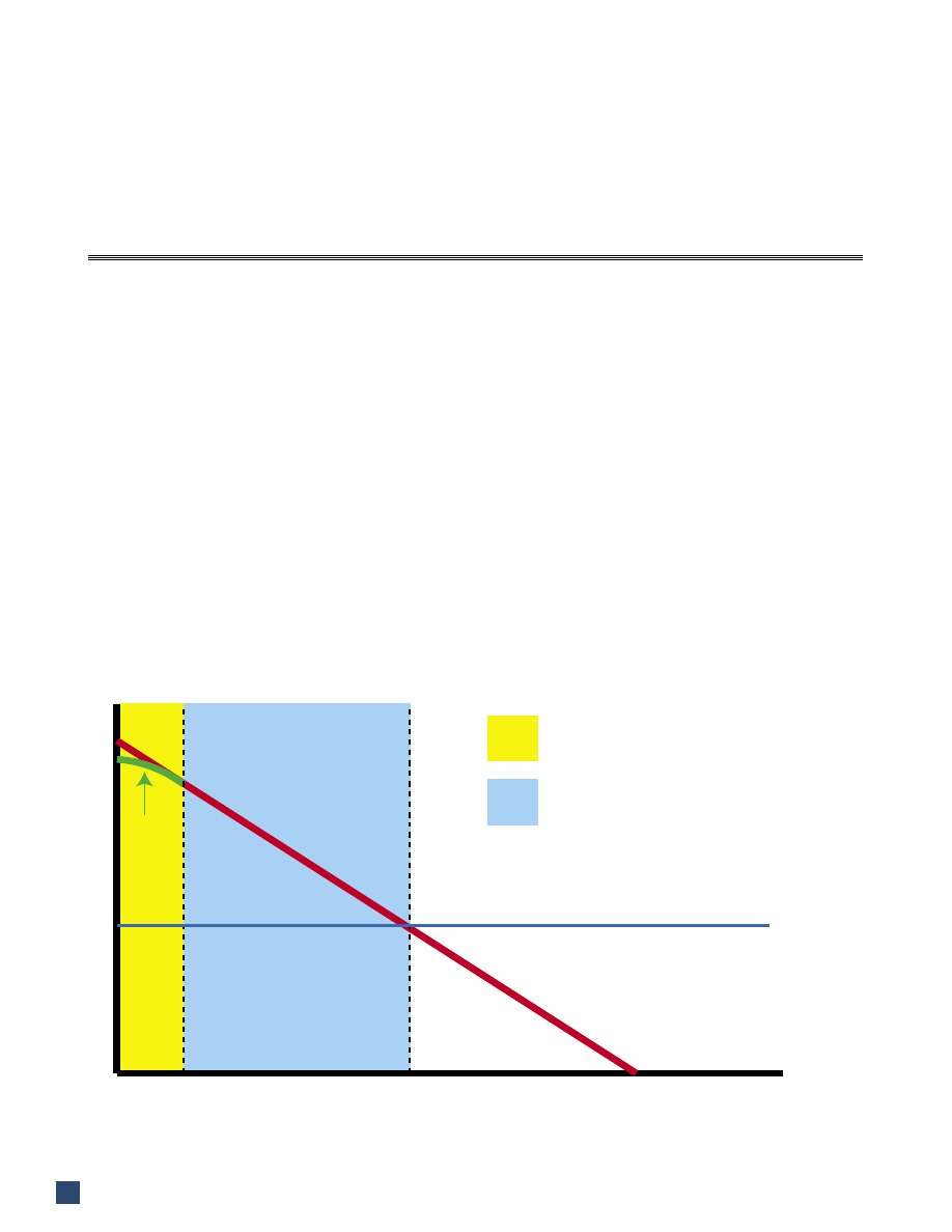
The most common reference distance for loudspeak-
er SPL specifications is 1 meter (3.28 feet). The choice
is one of convenience - any distance will do. The 1m
reference simplifies distance attenuation calculations by
eliminating the division required in the first step:
∆dB = 20log(D
x
/1)
ideal point source
∆dB = 10log(D
x
/1)
ideal line source
where D
x
is the listener position in meters.
Loudspeakers must be measured at a distance be-
yond which the shape of the radiation balloon remains
unchanged. The changes are caused by path length dif-
ferences to different points on the surface of the device.
These differences become increasingly negligible with
increasing distance from the source, much in the same
way as any object optically “shrinks” as the observer
moves to a greater distance. The distance at which the
path-length differences become negligible marks the
end of the near-field and beginning of the far-field of
the device.
An infinitely small source (a point source) can be
measured at any distance and the data extrapolated to
greater distances using the inverse-square law without
error. A very small loudspeaker might possibly be mea-
sured at 1 meter, but for larger loudspeakers it’s a differ-
ent story.
For large devices, the beginning of the far-field must
be determined, marking the minimum distance at radia-
tion parameters can be measured. The resultant data is
then referenced back to the 1 meter reference distance
(Figure 1) using the inverse-square law. This calculated
���
������
�����
�����
��������������
���������������������
���������������������������
�
�
�����������������
�����������������������������
����������������������������
Far-field Criteria for
Loudspeaker Balloon Data
by Pat Brown
Figure 1 - Loudspeaker radiation characteristics must be measured in the far-free field. They can then be extrapolated back
to a reference distance that lies in the near-field (i.e. 1 meter).
Newsletter
23
1 meter response can then be extrapolated to further dis-
tances with acceptable error.
A Rule-of-Thumb
A working “rule-of-thumb” for determining the
boundary between near-field and far-field is to make the
minimum measurement distance the longest dimension
of the loudspeaker multiplied by 3. While this estimate
is generally acceptable for field work, it ignores the fre-
quency-dependency of the transition between the near
and far fields.
More accurate estimates of the far field are found
to be:
1. The point of observation where the path length
differences to all points on the surface of the loudspeaker
perpendicular to the point of observation are the same.
Unfortunately this is at an infinite distance and the pres-
sure is zero.
2. The distance at which the loudspeaker’s three-
dimensional radiation balloon no longer changes with
increasing distance from the source with regard to fre-
quency.
3. The distance from the source where the radiated
level begins to follow the inverse-square law for all radi-
ated frequencies.
And, a practical definition useful for determining
the required measurement distance:
4. The distance from the source where the path
length difference for wave arrivals from points on the
device on the surface plane perpendicular to the point
of observation are within one-quarter wavelength at the
highest frequency of interest (Figure 2).
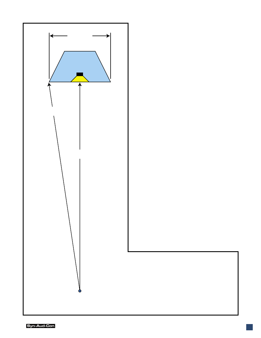
Consideration of any of these definitions reveals that
the far-field is wavelength (frequency)-dependent.
As previously stated, the need to measure loud-
����������������
��������
�����������
����������
����������
Figure 2 - The figure at left shows the path length dif-
ference to the microphone position for a loudspeaker
whose largest dimension is 2 feet. Note that even though
the transducer is smaller than the cabinet face, the en-
tire front baffle of the enclosure can radiate energy. At-
tenuation balloons for this loudspeaker can be measured
up to 17kHz at 9 meters. The upper practical limit for
loudspeaker modeling is 10kHz.
Vol 32 No. 4 Fall 2004
24
speakers in their far-field arises when it is necessary to
project the data to greater distances using the inverse-
square law, which is exactly what acoustic modeling
programs do. If this is not the purpose of the data, then
measurements can be carried out in the near-field. The
resultant data will be accurate for the position at which it
was gathered, but will be inappropriate for extrapolation
to greater distances using the ISL.
It is often thought that a remote measurement posi-
tion is necessary for low frequencies since their wave-
lengths are long. Actually the opposite is true. It is more
difficult to get into the far-field of a device at high fre-
quencies, since the shorter wavelengths make the crite-
ria in Item 4 more difficult to satisfy.
The most challenging loudspeakers to measure are
large devices that are radiating high frequencies from a
large area. The near-field can extend to hundreds of feet
for such devices, making it impractical or even impossi-
ble to get accurate balloon data with conventional mea-
surement techniques. Alternatives for obtaining radia-
tion data for such devices include acoustic modeling and
Acoustic Holography - a technique pioneered by Duran
Audio. David Gunness of EAW has authored several im-
portant papers on how such devices can be handled.
So, some factors tend to increase the required mea-
surement distance, and, as with all engineering endeav-
ors, there are also some factors that tend to reduce the
required distance. They include:
1. Large loudspeakers with extended HF response
do not typically radiate significant HF energy from the
entire face of the device. HF by nature is quite direc-
tional, making it more likely that the radiated energy is
localized to the HF component. As such, only the dimen-
sion of the HF device itself may need to be considered in
determining the far-field.
2. Beam-steered line arrays (i.e. Duran Intellivox
TM
or EAW DSA
TM
) do not radiate HF energy from their en-
tire length. The array length is made frequency-depen-
dent by band pass filters on each device. This may allow
a closer measurement distance than may be apparent at
first glance.
Passive line arrays (i.e. Bose MA12
TM
) are among
the most difficult devices to measure, especially when
used in multiples. Each device is full-range, so the path
length difference between the middle and end devices
can be quite large. A compromise is to measure the ra-
diation balloon of a single unit and predict the response
of multiples using array modeling software. Equally
difficult are large ribbon lines and planar loudspeakers,
again due to the large area from which high frequency
energy radiates.
It would appear that all that is necessary is to pick a
very large measurement distance. While this solves the
far-field problem, it creates a few also. They include:
1. Air absorption losses increase with distance.
While these can be corrected with equalization, the HF
boost puts a greater strain on the DUT.
2. It becomes increasingly difficult to maintain con-
trol over climate with increasing distance (drafts, tem-
perature gradients, etc.). These effects produce varia-
tions in the measured data, making the collection of
phase data difficult or impossible.
3. Indoors, the anechoic time span becomes shorter
with increasing distance, since the path
length difference to the ceiling, floor, or
side walls is reduced as the microphone is
moved farther from the source. The effect
is an increase in the lowest frequency that
can be measured anechoicly (a reduction
in frequency resolution).
4. Direct field attenuation will be 10dB
greater at 30m (100ft) than at 9m (30ft).
This reduces the signal-to-noise ratio of
the measured data by 10dB, or requires
that ten times the power be delivered to the
DUT to maintain the same S/N ratio that
exists at 30 feet.
5. Outdoor measurements are difficult
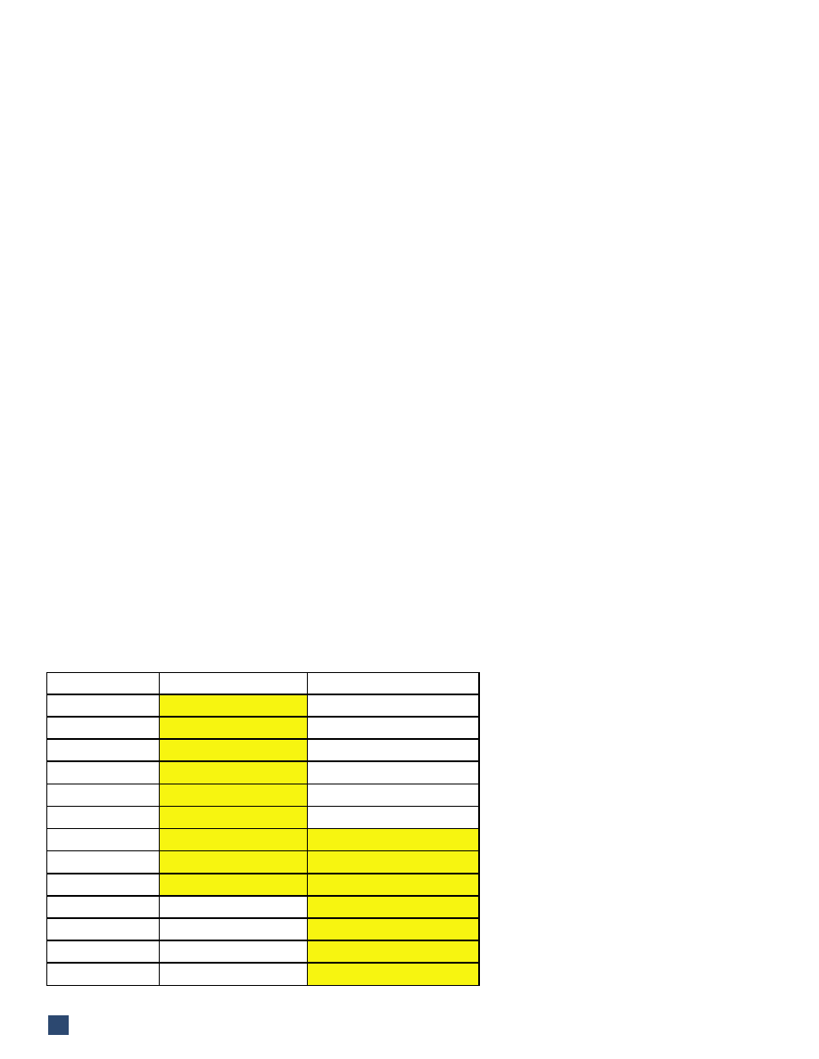
Lgst HF Dim.
HF Limit@30’(9m)
HF Limit at 100’(30m)
0.5 ft
271kHz
904kHz
1.0 ft
68kHz
226kHz
1.5 ft
30kHz
100kHz
2.0 ft
17kHz
56kHz
2.5 ft
11kHz
36kHz
3.0 ft
7.5kHz
25kHz
4ft
4.2kHz
14kHz
5ft
2.7kHz
9kHz
6ft
1.9kHz
6.3kHz
7ft
1.4kHz
4.6kHz
8ft
1.0kHz
3.5kHz
9ft
840Hz
2.8kHz
10ft
680Hz
2.2kHz
Fig. 3 - The upper frequency limit for two
measurement distances based on the size
of the HF radiator.
Newsletter
25
due to unstable noise and climate conditions over the
time span of the measurement (up to 8 hours).
Large measurement distances are possible if the
above problems are solved. A large aircraft hanger with
a time windowed impulse response represents a good
way to collect balloon data at remote distances.
Our chamber at ETC, Inc. allows measurement out
to 9 meters (30 feet). This is an adequate distance for
the majority of commercial sound reinforcement loud-
speakers, but not all of them. The loudspeaker rotator is
portable, so devices that cannot be measured at 9 meters
are measured in a very large space at a distance out to 30
meters (100 feet). A time window provides the required
reflected-field rejection. Determination of the required
measurement distance is made on a case-by-case basis
after considering the device-to-be-tested.
Using the above criteria for the far-field, and fixing
a measurement distance of 30 feet (9m), the highest fre-
quency balloon possible for different size devices can be
determined (Figure 3).
Note that this is the largest dimension of the HF de-
vice. If the far-field condition is met for it, it will typi-
cally be met for all lower frequencies.
The far-field prerequisite for loudspeaker attenua-
tion balloons must be met to allow the data to be pro-
jected from one meter to listener seats with acceptable
error. The condition is easily satisfied for physically
small devices, i.e. bookshelf loudspeakers. Since sound
reinforcement loudspeakers are often physically large,
there exists a highest frequency limitation in what can
be measured at a fixed measurement distance. Ideally,
data for which the far-field criteria is not met should be
excluded or marked as suspect on specification sheets
or within design programs. Usually it is not, so the user
must use some intuition in HF modeling of sound cover-
age in auditoriums. pb
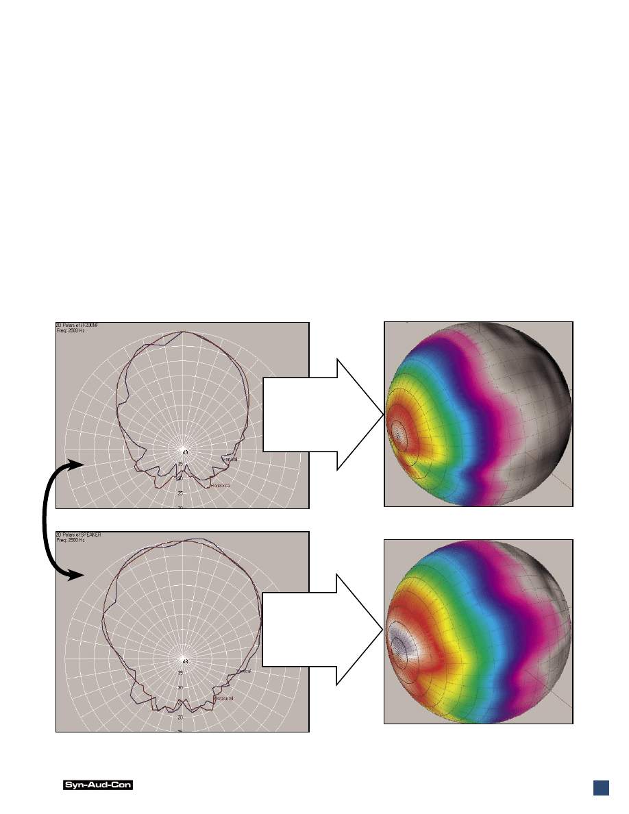
Near-field
response at
crossover.
Far-field
response at
crossover.
The near-field response “morphs” into the far-field response with increasing distance.
Edge-diffraction and reduced path-length differences smooth the balloon in the far-field.
Wyszukiwarka
Podobne podstrony:
Field of Glory Errata
Constructing the Field
crc press cyber crime investigator 27s field guide
far leki miejscowo znieczulające, Farmacja, Farmakologia(1), Znieczulenie miejscowe
tabelka do sprawozdań, far, II rok III sem, analiza instrumentalna
zaliczenie farmacja 2010, far, II rok III sem, psychologia
Psychologia, far, II rok III sem, psychologia, psychologia
far skrypt 6
IMMUNOPROFILAKTYKA CHOR B ZAKA NYCH ZWIERZ T, far, II rok III sem, zwierzęta laboratoryjne, z poprze
2015, far, III rok IV sem, mikroby 2015
ZIELNIK, far, botanika
Osobowosci małzeńskie - FIELD, Testy psychologiczne, Sądówka
2?far tekst
far skrypt 6
International Field Position
Japan Business Culture Field Report
PHYWE P2450800 Radiation field of a horn antenna Microwaves
Notes on the 3 inch gun materiel and field artillery equipment 1917
1942 WLA Generator Field Switch Doc
więcej podobnych podstron