voltage on to C1, which charges up to a voltage, deter-
mined by the voltage divider R1/R2, that is 0.3 V higher than
the output voltage. The small charging peaks shown in
curve 2 are not drawn to scale. If V
LX
is more than 0.7 V
lower than V
C1
, transistor T conducts and passes the volt-
age across C1 on to C2. The small voltage sags shown in
curve 3 are also not drawn to scale, for the sake of clarity.
If the step-up regulator IC is disabled, the voltage across
C1 will be only as high as the input voltage. This voltage is
also present at LX, so there is not enough base bias volt-
age to switch on the transistor, and it is cut off.
(014080-1)
SUMMER CIRCUITSCOLLECTION
78
Elektor Electronics
7-8/2001
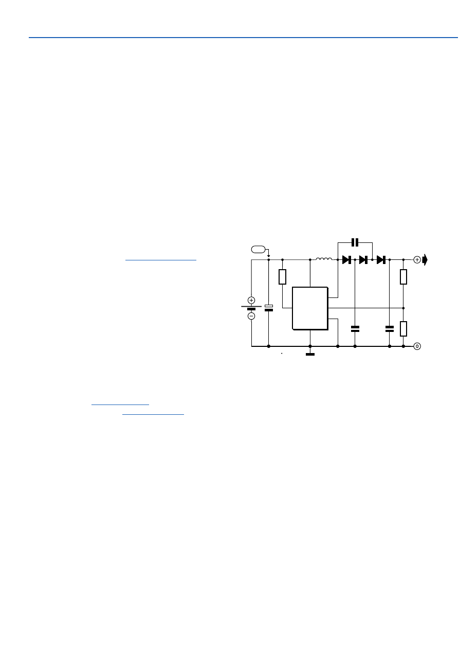
The circuit shows one way of obtaining a voltage of 90 V
from a 1.5 V battery supply. The LT1073 switching regula-
tor from Linear Technology (
www.linear-tech.com
) oper-
ates in boost mode and can work with an input voltage as
low as 1.0 V. The switching transistor, which is hidden
behind connections SW1 and SW2, briefly takes one end of
choke L1 to ground. A magnetic field builds up in the
choke, which collapses when the transistor stops conduct-
ing: this produces a current in diode D1 which charges C3.
The diode cascade comprising D1, D2, D3, C2, C3 and C4
multiplies the output voltage of the regulator by four, the
pumping of C2 causing the voltage developed across C4
via C3, D2 and D3 to rise. Finally, the regulator control loop
is closed via the potential divider (10 M
Ω
and 24 k
Ω
).
These resistors should be 1 % tolerance metal film types.
With the given component values, fast diodes with a
reverse voltage of 200 V (for example type MUR120 from
On Semiconductor
www.onsemi.com
) and a choke such as
the Coilcraft DO1608C-154 (
www.coilcraft.com
) an output
voltage of 90 V will be obtained. The output of the circuit
can deliver a few milliamps of current.
(014113-1)
043
LT1073
IC1
VIN
GND
SW1
SW2
IL
FB
5
2
3
1
8
4
R1
220
Ω
R2
10M
1%
R3
24k
1%
C1
10µ
C4
470n 100V
C2
470n
100V
BT1
1V5
L1
150µH
D1
D2
D3
C3
470n 100V
+90V
D1...D3 = MUR120
*
014113 - 11
1V5
zie tekst
*
see text
*
siehe Text
*
voir texte
*
10V
High Voltage Converter:
90 V from 1.5 V
In the December issue we’ll describe a fancy Li-Ion
charger based on a specially designed IC and boasting
many bells and whistles. However, it can also be done in a
much simpler way, provided you are prepared to work
carefully. The latter is particularly important, because we
will point out again that charging Li-ion batteries with a
voltage that is too high can cause explosions! In this
respect Li-ion batteries are not the least comparable with
the much less critical NiCd- or NiMH-types.
Li-ion batteries may, just like lead-acid batteries, be
charged with a constant voltage. The charging voltage for a
3.6 V cell is 4.1 V maximum, and for 3.7 V cells this is 4.2 V.
Higher voltages are not permissible; lower voltages are,
but every 0.1 V results in a reduction of capacity of about
7%. As a consequence, great precision is required and it is
therefore highly recommended to measure the output volt-
age with an accurate (less than 1% error) digital voltmeter.
A good stabilised lab power supply is in principle perfectly
suited as a Li-Ion charger. Adjust it to 4.1 V (or 8.2 V if you
are charging two cells in series) and also adjust the current
limiting to an appropriate value, 1 C for example (where C
is the capacity, e.g.,. 1 A for a 1 Ah battery). A too low value
044
Lithium-Ion Charger II
Wyszukiwarka
Podobne podstrony:
e017042
e017040
e017048
e017049
e017047
e017046
e017041
e017044
e017045
e017042
e017047
e017043
e017049
więcej podobnych podstron