
KUKA System Technology
KUKA.Load 5.0
KUKA.Load Pro 5.0
Valid for KSS 5.5, 5.6, 8 and VSS 8
KUKA Roboter GmbH
Issued: 06.05.2013
Version: KUKA.Load 5.0 V2 en (PDF)

KUKA.Load 5.0 KUKA.Load Pro 5.0
Issued: 06.05.2013 Version: KUKA.Load 5.0 V2 en (PDF)
© Copyright 2013
KUKA Roboter GmbH
Zugspitzstraße 140
D-86165 Augsburg
Germany
This documentation or excerpts therefrom may not be reproduced or disclosed to third parties without
the express permission of KUKA Roboter GmbH.
Other functions not described in this documentation may be operable in the controller. The user has
no claims to these functions, however, in the case of a replacement or service work.
We have checked the content of this documentation for conformity with the hardware and software
described. Nevertheless, discrepancies cannot be precluded, for which reason we are not able to
guarantee total conformity. The information in this documentation is checked on a regular basis, how-
ever, and necessary corrections will be incorporated in the subsequent edition.
Subject to technical alterations without an effect on the function.
Translation of the original documentation
KIM-PS5-DOC
Publication:
Pub KUKA.Load 5.0 (PDF) en
Bookstructure:
KUKA.Load 5.0 V1.1
Version:
KUKA.Load 5.0 V2 en (PDF)

Issued: 06.05.2013 Version: KUKA.Load 5.0 V2 en (PDF)
Contents
..................................................................................................
5
Target group ..............................................................................................................
5
Representation of warnings and notes ......................................................................
5
Trademarks ................................................................................................................
5
Terms used ................................................................................................................
6
.....................................................................................
7
KUKA.Load and KUKA.Load Pro ...............................................................................
7
Overview of KUKA.Load ............................................................................................
7
Load data ...................................................................................................................
8
Loads on the robot ................................................................................................
8
Static overloading of the robot ..............................................................................
9
Dynamic overloading of the robot .........................................................................
9
Cycle time analysis recommended .......................................................................
10
Robots in palletizing mode (KUKA.Load Pro) ............................................................
10
...................................................................................................
11
System requirements .................................................................................................
11
Installing or updating KUKA.Load ..............................................................................
11
Uninstalling KUKA.Load .............................................................................................
11
.............................................................................
13
KukaLoadGUI graphical user interface ......................................................................
13
“Preselection” area ...............................................................................................
15
“Load data” area ...................................................................................................
16
Tabs ......................................................................................................................
17
The project window ....................................................................................................
18
“Robot types” area ................................................................................................
20
The project window (KUKA.Load Pro) .......................................................................
20
“Robot types” area (KUKA.Load Pro) ...................................................................
22
......................................................................................................
25
Starting KUKA.Load ...................................................................................................
25
Changing the unit of measurement ............................................................................
25
Changing the user interface language .......................................................................
25
Creating a project file .................................................................................................
25
Loading a project file ..................................................................................................
25
Opening a project file .................................................................................................
26
Performing a load analysis .........................................................................................
26
Using the “Add tool data” button ................................................................................
27
Searching for a robot .................................................................................................
28
5.10 Comparing robots ......................................................................................................
29
5.11 Saving the robot in the project ...................................................................................
30
5.12 Changing the saved load case of a robot ..................................................................
30
5.13 Merging 2 project files manually (KUKA.Load Pro) ....................................................
30
5.14 Merging 2 project files automatically (KUKA.Load Pro) .............................................
31
5.15 Merging multiple project files (KUKA.Load Pro) .........................................................
31
5.16 Creating a sign-off sheet ............................................................................................
32
Contents

Issued: 06.05.2013 Version: KUKA.Load 5.0 V2 en (PDF)
KUKA.Load 5.0 KUKA.Load Pro 5.0
5.17 Creating multiple sign-off sheets simultaneously (KUKA.Load Pro) ..........................
34
...............................................................................................
37
Requesting support ...................................................................................................
37
KUKA Customer Support ...........................................................................................
37
Issued: 06.05.2013 Version: KUKA.Load 5.0 V2 en (PDF)
1 Introduction
1
Introduction
1.1
Target group
This documentation is aimed at users with the following knowledge and skills:
Knowledge of robotics
Advanced knowledge of dynamic and static loading on the robot
Basic knowledge of the Windows operating system
1.2
Representation of warnings and notes
Safety
These warnings are relevant to safety and must be observed.
This warning draws attention to procedures which serve to prevent or remedy
emergencies or malfunctions:
Notes
These hints serve to make your work easier or contain references to further
information.
1.3
Trademarks
Windows
is a trademark of Microsoft Corporation.
.NET Framework
is a trademark of Microsoft Corporation.
Office 2003
is a trademark of Microsoft Corporation.
For optimal use of our products, we recommend that our customers
take part in a course of training at KUKA College. Information about
the training program can be found at www.kuka.com or can be ob-
tained directly from our subsidiaries.
These warnings mean that it is certain or highly probable
that death or severe injuries will occur, if no precautions
are taken.
These warnings mean that death or severe injuries may
occur, if no precautions are taken.
These warnings mean that minor injuries may occur, if
no precautions are taken.
These warnings mean that damage to property may oc-
cur, if no precautions are taken.
These warnings contain references to safety-relevant information or
general safety measures.
These warnings do not refer to individual hazards or individual pre-
cautionary measures.
Procedures marked with this warning must be followed
exactly.
Tip to make your work easier or reference to further information.
Issued: 06.05.2013 Version: KUKA.Load 5.0 V2 en (PDF)
KUKA.Load 5.0 KUKA.Load Pro 5.0
1.4
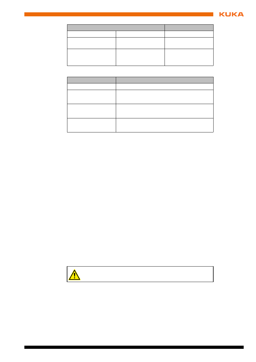
Terms used
Term
Description
Dynamic loading
Utilization of the range in which stable motion
characteristics are expected.
Dynamic overloading
The load data are out of specification.
Total load
All payloads and supplementary loads are added
together to give the total load.
Imperial measure-
ment system
Measurement system in which the inch [in] is a
base unit.
Load case
A load case consists of the load data of the pay-
load on the flange and the supplementary loads
on axes A1 to A3.
Metric measurement
system
Measurement system in which the meter [m] is a
base unit.
Station
At a given plant there may be one or more sta-
tions. A number of robots (e.g. welding robots)
may be used in a given station.
Issued: 06.05.2013 Version: KUKA.Load 5.0 V2 en (PDF)
2 Product description
2
Product description
2.1
KUKA.Load and KUKA.Load Pro
KUKA.Load Pro is an expanded version of KUKA.Load with additional func-
tions. Everything described below for KUKA.Load is also valid for KUKA.Load
Pro. Everything that applies only to KUKA.Load Pro is marked accordingly.
2.2
Overview of KUKA.Load
Functions
KUKA.Load is a software package with the following functions:
Checking whether a robot is suitable for a particular load case
Searching for suitable robots for a particular load case
Calculating the load for several tools mounted simultaneously on the robot
Generating a message in the event of static overloading
Generating a message in the event of dynamic overloading
Generating a message if cycle time analysis is recommended
Creating acceptance reports (sign-off sheets)
Managing projects with a number of robots and their load cases
Comparing a number of robots with regard to a particular load case
(
>>>
4.1 "KukaLoadGUI graphical user interface" Page 13)
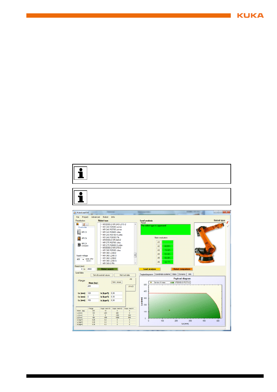
KUKA.Load 5.0 must only be used in conjunction with KSS 5.5, 5.6,
8 or VSS 8. The expanded control algorithms in these versions allow
higher loads.
General process forces cannot be considered by the software.
Fig. 2-1: KUKA.LoadGUI graphical user interface
Issued: 06.05.2013 Version: KUKA.Load 5.0 V2 en (PDF)
KUKA.Load 5.0 KUKA.Load Pro 5.0
2.3
Load data
The load data must be entered in the robot controller. The load data are fac-
tored into the calculation of the paths and accelerations and help to optimize
the cycle times.
2.3.1
Loads on the robot
Description
Various loads can be mounted on the robot:
Payload on the flange
Supplementary load on axis 3
Supplementary load on axis 2
Supplementary load on axis 1
All loads added together give the overall load.
Parameters
The load data are defined using the following parameters:
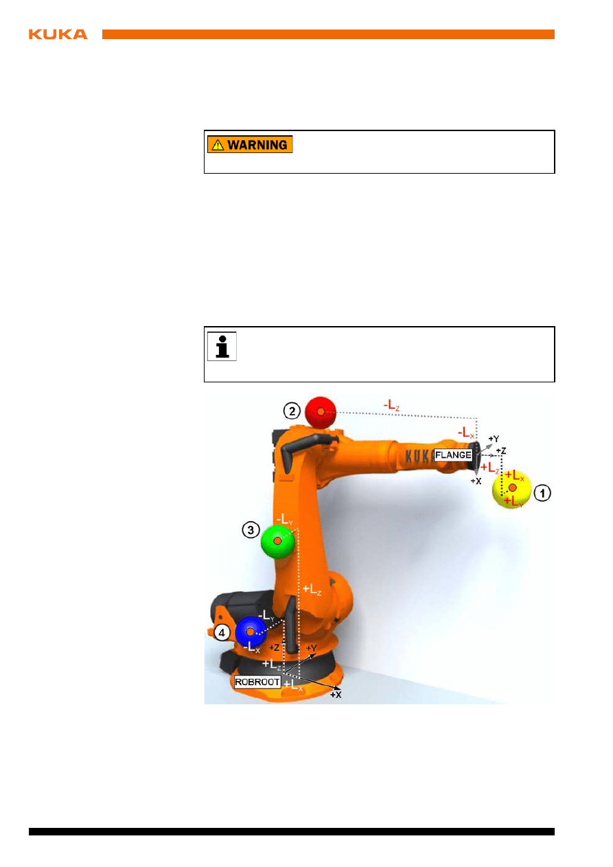
The robot must not be operated with incorrect load data
or unsuitable loads. Failure to observe this precaution
may result in severe injuries or considerable damage to property.
There is a payload diagram for every robot. This can be used to make
a quick preliminary check of whether the robot is suitable for the pay-
load. The diagram is not, however, a substitute for checking the pay-
load with KUKA.Load.
Fig. 2-2: Loads on the robot
1
Payload
3
Supplementary load on axis 2
2
Supplementary load on axis 3
4
Supplementary load on axis 1
Issued: 06.05.2013 Version: KUKA.Load 5.0 V2 en (PDF)
2 Product description
Reference systems of the X, Y and Z values for each load:
Sources
Load data can be obtained from the following sources:
Software option KUKA.LoadDetect (only for payloads on the flange)
Manufacturer information
Manual calculation
CAD programs
2.3.2
Static overloading of the robot
Description
Static analyses are carried out to check the static load on the overall robot and
compared with maximum permissible values. In particular, this includes the
gear and motor holding torques which are mapped to a specific axis. If these
are not sufficient for an overall static evaluation of the robot, equivalent struc-
tural loads are considered, which can also be mapped to a corresponding axis.
For example, there is no static torque on axis 6 of a palletizing robot, but a load
is nonetheless documented.
If the maximum permissible values are exceeded, this is referred to as static
overloading of the robot. This overloading can be prevented by means of the
following measures:
Shifting the position of the center of gravity towards the flange center point
Using a robot with a higher rated payload
Reducing the mass/weight
2.3.3
Dynamic overloading of the robot
Description
If the load data are out of specification, this is referred to as dynamic overload-
ing of the robot. This overloading can be prevented by means of the following
measures:
Reduce the mass moments of inertia by:
Using a more geometrically compact load
Reducing the mass
Parameter
Unit
Mass
m
kg
Distance to the center
of gravity
L
x
, L
y
, L
z
mm
Mass moments of iner-
tia at the center of
gravity
I
x
, I
y
, I
z
kg m
2
Load
Reference system
Payload
FLANGE coordinate system
Supplementary load
A3
FLANGE coordinate system
A4 = 0°, A5 = 0°, A6 = 0°
Supplementary load
A2
ROBROOT coordinate system
A2 = -90°
Supplementary load
A1
ROBROOT coordinate system
A1 = 0°
KUKA Roboter GmbH must always be consulted in the case of over-
loading.
Issued: 06.05.2013 Version: KUKA.Load 5.0 V2 en (PDF)
KUKA.Load 5.0 KUKA.Load Pro 5.0
Using a robot with a higher rated payload
2.3.4
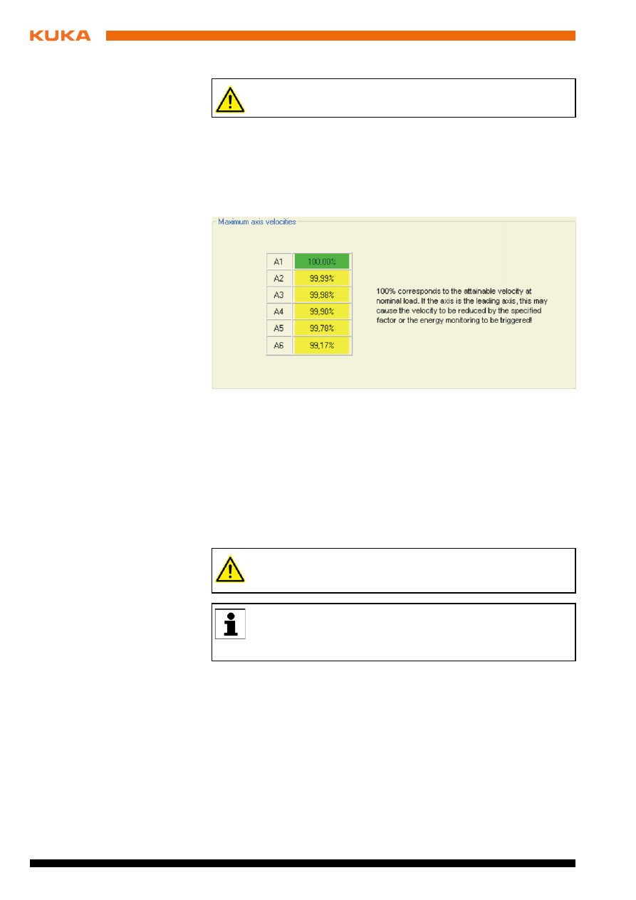
Cycle time analysis recommended
Description
100% corresponds to the attainable velocity at nominal load. If the axis is the
leading axis, this may cause the velocity to be reduced or the energy monitor-
ing to be triggered.
2.4
Robots in palletizing mode (KUKA.Load Pro)
Description
In KUKA.Load Pro, when Palletizer is set under “Preselection”, the list of robot
types displayed also includes robots with 6 axes. The static and dynamic load-
ing of these robots is analyzed on the basis of the higher loads permitted in
palletizing mode. The analysis is therefore only valid if the robot is operated in
palletizing mode. If the robot receives a release for the analysis, a correspond-
ing message will be displayed.
KUKA Roboter GmbH must always be consulted in the case of over-
loading.
Fig. 2-3: Velocity tab – example
When using robots in palletizing mode, it must be ensured that the
safety instructions and the specified operation of the robot in palletiz-
ing mode are observed.
Further information about operating robots in palletizing mode is con-
tained in the operating and programming instructions of the KUKA
System Software (KSS) in the chapter “Start-up and recommission-
ing” in the section “Activating palletizing mode”.
Issued: 06.05.2013 Version: KUKA.Load 5.0 V2 en (PDF)
3 Installation
3
Installation
3.1
System requirements
Hardware
Minimum requirements
PC with Pentium processor, min. 1500 GHz
512 MB RAM
Graphics card with a resolution of at least 1024 x 768 pixels
Recommended equipment
PC with Pentium processor, min. 2500 GHz
2 GB RAM
Graphics card with a resolution of at least 1280 x 1024 pixels
Software
Windows XP (32-bit) or Windows 7 (32-bit / 64-bit)
.NET Framework 4.0 and 3.5 SP1
If sign-off sheets are to be created: Microsoft Office 2003 or higher
3.2
Installing or updating KUKA.Load
Precondition
Local administrator rights
All Windows applications are closed.
Procedure
1. Start the program setup.exe.
2. If the following component is not yet installed on the PC, an installation
wizard opens:
.NET Framework 4.0
Follow the instructions in the installation wizard. .NET Framework is in-
stalled.
3. If the following component is not yet installed on the PC, an installation
wizard opens:
Visual C++ Runtime Libraries
Follow the instructions in the installation wizard. Visual C++ Runtime Li-
braries is installed.
4. The installation wizard for KUKA.Load opens. Confirm with Next >.
5. For KUKA.Load Pro only: Accept the license agreement and click on
Next >
.
6. Select the directory and confirm with Next >.
7. Confirm installation with Next >. Installation is carried out.
8. When the installation wizard reports that KUKA.Load has been installed,
close the installation wizard with Close.
3.3
Uninstalling KUKA.Load
Precondition
Local administrator rights
All Windows applications are closed.
Procedure
Uninstall KUKA.Load via the Windows Control Panel.
In the case of an update, the previously installed version is uninstalled
automatically. It is advisable to archive all relevant data before updat-
ing.

Issued: 06.05.2013 Version: KUKA.Load 5.0 V2 en (PDF)
4 Graphical user interface
4
Graphical user interface
4.1
KukaLoadGUI graphical user interface
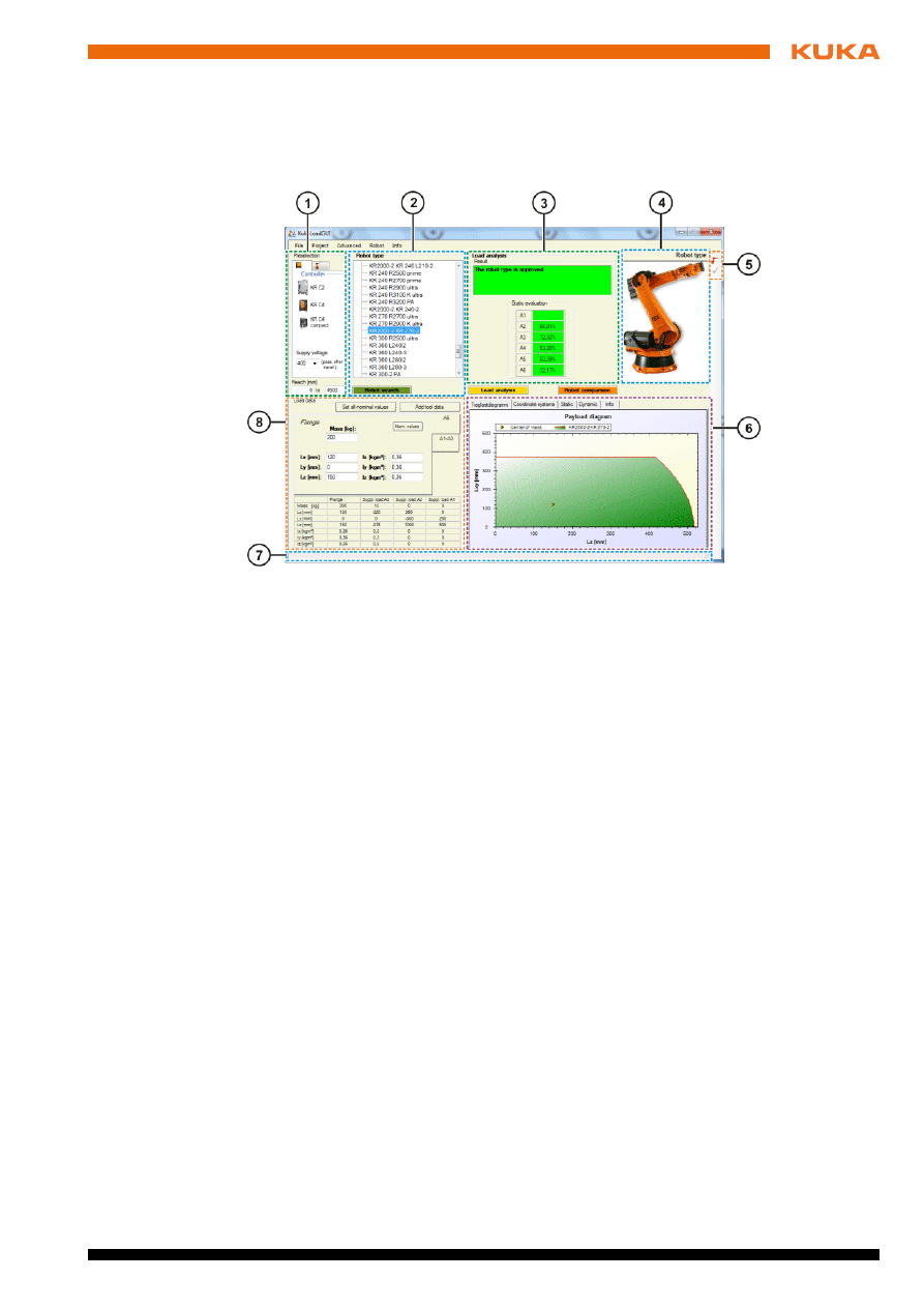
Overview
Fig. 4-1: KUKA.LoadGUI graphical user interface
1
Preselection
area
5
Toolbar
2
Robot type
area
6
Area with tabs
3
Load analysis
area
7
Status bar
4
Picture of robot type
8
Load data
area
14 / 47
Issued: 06.05.2013 Version: KUKA.Load 5.0 V2 en (PDF)
KUKA.Load 5.0 KUKA.Load Pro 5.0
Areas
Buttons
Area
Description
Preselection
In the Preselection area, the displayed robot types
can be filtered using the following criteria:
Controller
Supply voltage
Configuration
Reach [mm]
(
>>>
4.1.1 "“Preselection” area" Page 15)
Robot type
In the Robot type area, all the robots are shown that
correspond to the current preselection. These robots
are particularly suitable for the selected controller and
supply voltage.
The general conditions for operation of the controller
with the corresponding mains power supply can be
found in the robot controller documentation.
The specified supply voltage refers to the input supply
voltage to the controller and can if necessary be gener-
ated by a transformer connected upstream of the con-
troller.
Note
: In KUKA.Load Pro, when Palletizer is set under
“Preselection”, the list of robot types displayed also
includes robots with 6 axes. When using these robots,
it must be ensured that the safety instructions and the
specified operation of the robot in palletizing mode are
observed.
Load
analysis
After the analysis, the results and the static evaluation
are shown in the Load analysis area.
If one or more of the axes are overloaded, these have a
red background.
Load data
The view of the Load data area changes depending on
whether “Payload” or “Supplementary loads” is
selected.
(
>>>
4.1.2 "“Load data” area" Page 16)
Tabs
The following tabs are available:
Payload diagram
Coordinate systems
Static
Dynamic
Velocity
Info
(
>>>
Button
Description
Robot search
Enter the payload and supplementary loads in the
Load data
area. On pressing the button, 2 robots are
determined which are recommended for the load case.
Potential suitable robots for this load case are dis-
played in the Robot type area.
Issued: 06.05.2013 Version: KUKA.Load 5.0 V2 en (PDF)
4 Graphical user interface
Toolbar
Status bar
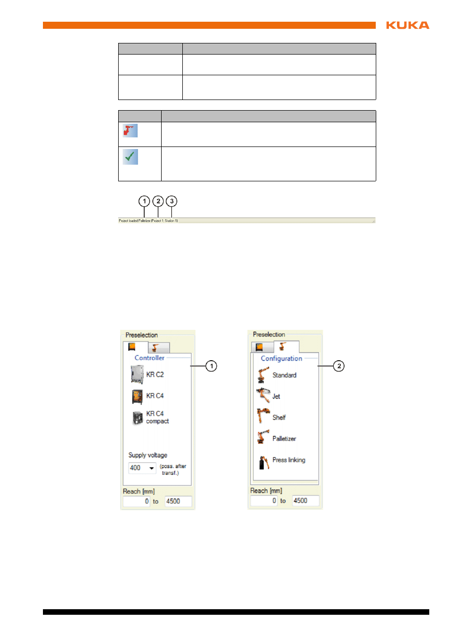
4.1.1
“Preselection” area
Description
The Preselection area features a tab for the controller and a tab for the ma-
nipulator configuration.
On the tab for the controller, you can select between the controllers KR C2,
KR C4
and KR C4 compact.
Load
analysis
During the load analysis, the selected robot is analyzed
for the entered load case.
Robot compari-
son
Up to 3 robots can be compared.
(
>>>
5.10 "Comparing robots" Page 29)
Button
Description
Icon
Description
Add robot with load case to a project.
Precondition: A project file is loaded.
Update the load case of a robot in a project.
Precondition: A link is established between the open project
file and the graphical user interface.
Fig. 4-2
1
Name of the project file
3
Number of the station
2
Name of the project
Fig. 4-3: “Preselection” area
1
Tab for the controller
2
Tab for the configuration
16 / 47
Issued: 06.05.2013 Version: KUKA.Load 5.0 V2 en (PDF)
KUKA.Load 5.0 KUKA.Load Pro 5.0
On the tab for the configuration, the displayed robot types can be filtered by
specifying the configuration. The Standard configuration includes 6-axis, 7-
axis and hollow-shaft robots.
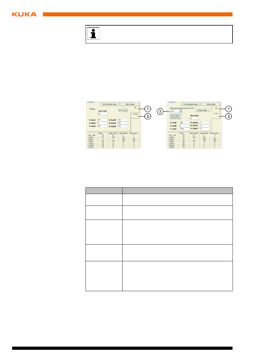
4.1.2
“Load data” area
Description
In this area the payload and supplementary loads are entered. These values
can be entered manually in the boxes, or automatically using the buttons Set
all nominal values
, Nom. values or Nom. values of all suppl. loads.
Buttons
No information is displayed as to whether the robot type is approved
for the selected controller and supply voltage. For further information,
please contact KUKA Service.
Fig. 4-4: “Load data” area
1
Tab for A6 (payload)
2
Tab for A1-A3 (supplementary loads)
3
Selection of axes A1 to A3
Button
Description
Set all nominal
values
The nominal values are entered for the payload and
supplementary loads.
Nom. values
The nominal values are entered for the payloads.
This button is displayed when the A6 tab is selected.
Nom. values of
all suppl. loads
The nominal values are entered for the supplementary
loads A1-A3.
This button is displayed when the A1-A3 tab is
selected.
Add tool data
The Add tool data button allows several loads to be
added together to make a total load. (
>>>
the “Add tool data” button" Page 27)
Energy supply
An energy supply system can be selected. The load
data for the energy supply system are assigned to the
supplementary load on axis 3.
This button is displayed when the A1-A3 tab is
selected.
Issued: 06.05.2013 Version: KUKA.Load 5.0 V2 en (PDF)
4 Graphical user interface
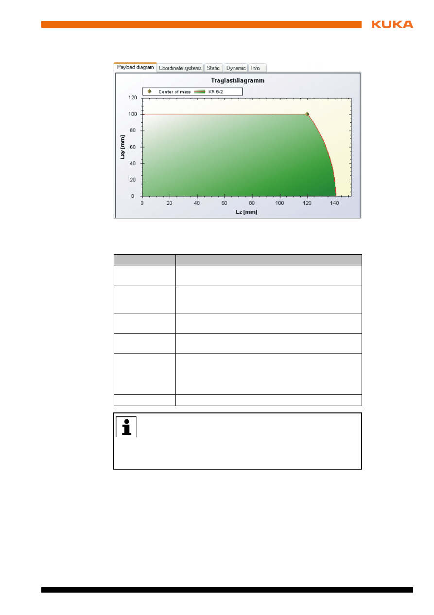
4.1.3
Tabs
Description
The following tabs are available:
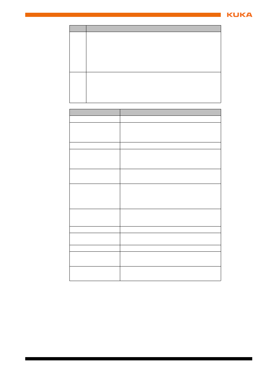
In the following load cases, the payload diagram is not shown:
Very low loading
The payload diagram is shown as a green color gradient.
Very high loading
The payload diagram is outside of the display range and is shown as a red
color gradient.
Fig. 4-5: Tabs
Tab
Description
Payload
diagram
The calculated payload diagram is displayed.
Coordinate
systems
The position and orientation of the coordinate system
on the flange or of the coordinate systems on the sup-
plementary loads of axes A1-A3.
Static
The static loading of the axes is shown in a bar dia-
gram.
Dynamic
The dynamic loading of the axes is shown in a bar dia-
gram.
Velocity
The maximum velocities relative to the attainable
velocities at nominal load are shown.
Note
: The Velocity tab is only available if a cycle time
analysis is recommended after a load analysis.
Info
Information about overloading.
The diagrams on the Payload diagram, Static and Dynamic tabs
have a pop-up menu containing various functions. For example, the
diagrams can be copied, saved and printed via the pop-up menu.
Furthermore, an area of the diagram can be increased or decreased in size
by scrolling. It is also possible to enlarge an area by dragging a frame over
the area with the mouse.
18 / 47
Issued: 06.05.2013 Version: KUKA.Load 5.0 V2 en (PDF)
KUKA.Load 5.0 KUKA.Load Pro 5.0
4.2
The project window
Description
When a project file is created, a project window opens with the name of the
created project file. The project file can contain several projects and individual
stations. Each station can be assigned a number of robots with different load
cases.
Fig. 4-6: Payload diagram cannot be shown (example)
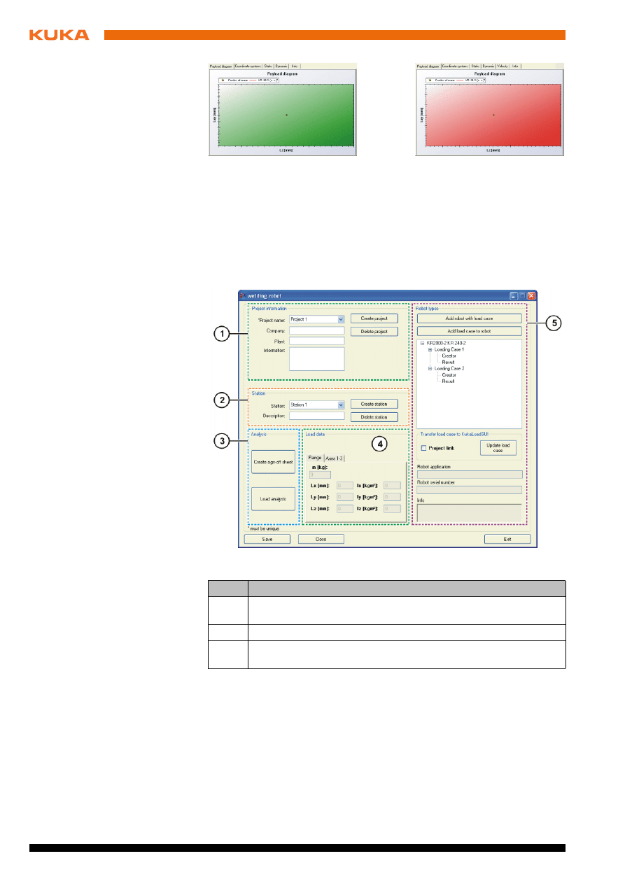
Fig. 4-7: Project window
Item
Description
1
In the Project information area, information about the project
can be entered.
2
In the Station area, information about the station can be entered.
3
In the Analysis area, a load analysis can be carried out for a load
case, and a sign-off sheet can be created.
Issued: 06.05.2013 Version: KUKA.Load 5.0 V2 en (PDF)
4 Graphical user interface
Buttons
4
In the Load data area, the selected robot and its load case are
shown. The payload and supplementary loads are displayed sep-
arately.
Mass
Distance to the center of gravity (L
x
, L
y
, L
z
)
Mass moments of inertia at the center of gravity (I
x
, I
y
, I
z
)
5
In the Robot types area, robots and load cases can be added. A
link can be established between the project window and the
graphical user interface. Information is displayed about the proj-
ect; this can be changed.
(
>>>
4.2.1 "“Robot types” area" Page 20)
Item
Description
Button
Description
Create project
Create a new project.
Delete project
Delete the selected project.
Note
: Only possible if at least one other project
has been created in the project file.
Create station
Create a new station.
Delete station
Delete the selected station.
Note
: If only one station has been created, the
higher-level project is deleted.
Create sign-off sheet
Create a sign-off sheet.
The Sign-Off Sheet window is displayed.
Load analysis
Carry out a load analysis for the selected robot
and its load case.
Note
: The result is displayed in the project infor-
mation.
Add robot with load
case
Transfer a robot selected on the KukaLoadGUI,
together with its current load case, to the station
of the current project.
Add load case to robot
Add a further load case to a robot.
Update load case
Transfer load data for the selected load case to
the project.
Save
Save the project file.
Close
Close the project window.
Note
: The project file remains loaded.
Exit
Close the project.
The project window and project file are closed.
20 / 47
Issued: 06.05.2013 Version: KUKA.Load 5.0 V2 en (PDF)
KUKA.Load 5.0 KUKA.Load Pro 5.0
4.2.1
“Robot types” area
4.3
The project window (KUKA.Load Pro)
Description
When a project file is created, a project window opens with the name of the
created project file. The project file can contain several projects and individual
stations. Each station can be assigned a number of robots with different load
cases.
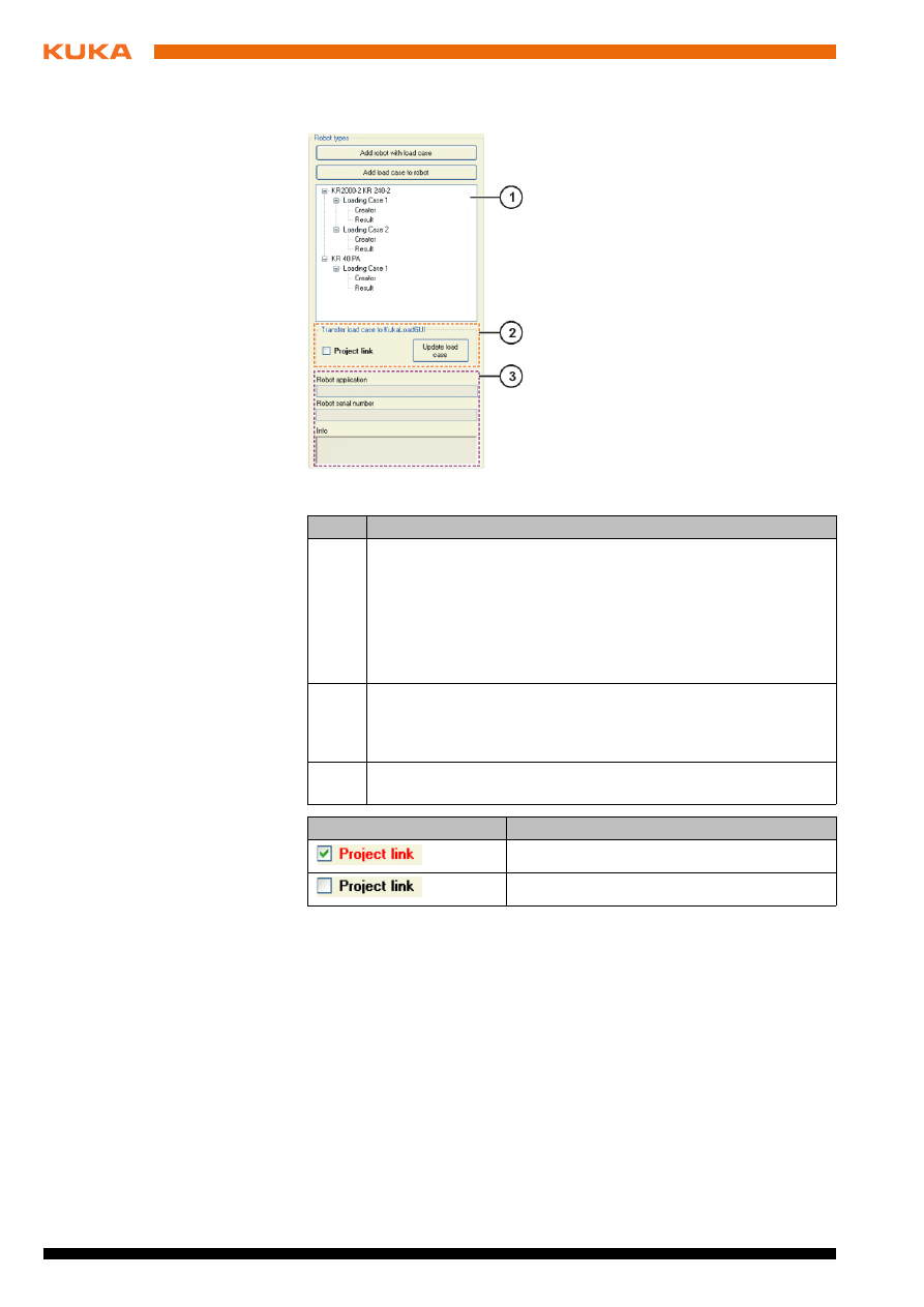
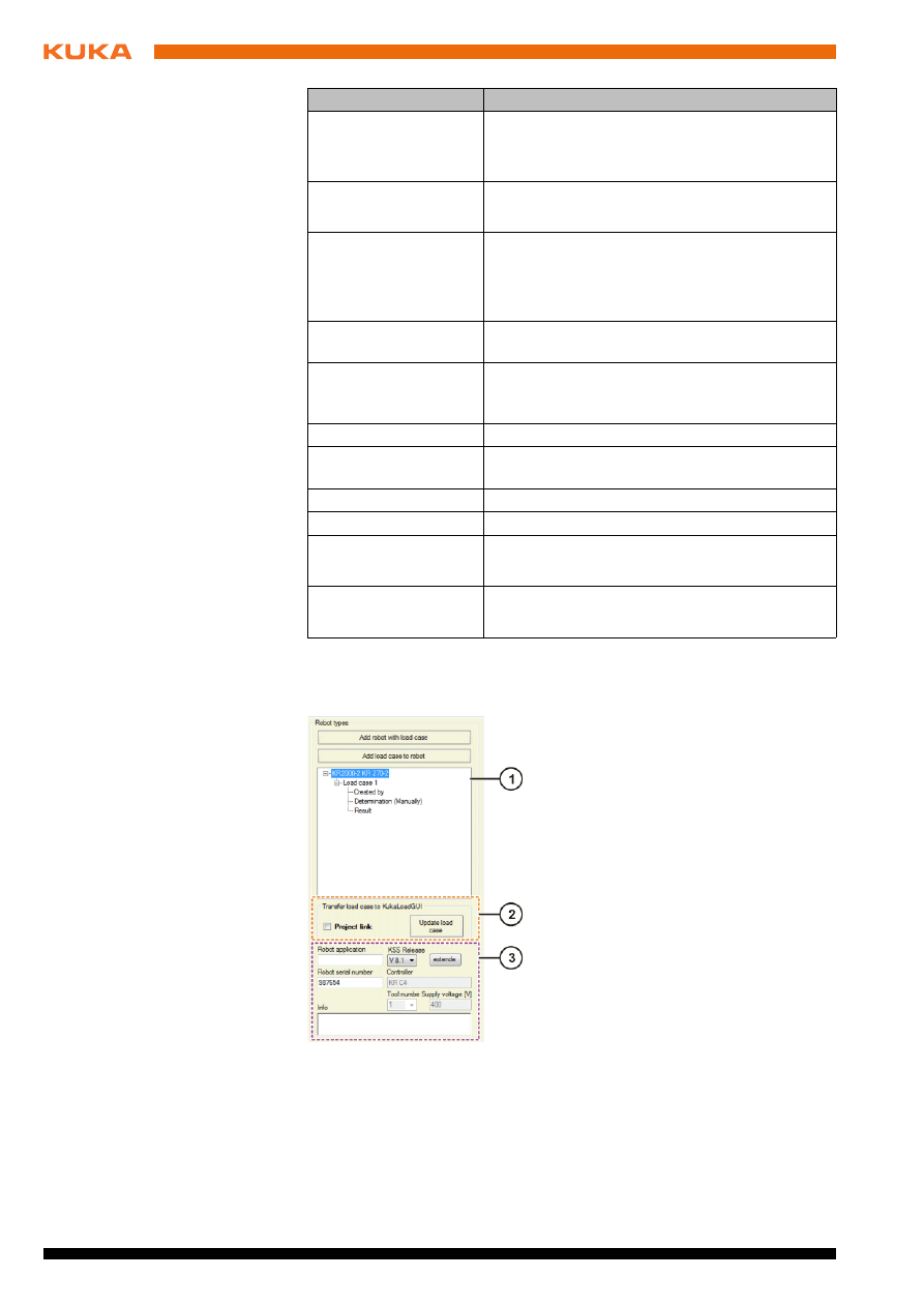
Fig. 4-8: “Robot type” area
Item
Description
1
In this box, the robots are shown with their load cases in a tree
structure. Each load case is assigned an originator and a result.
With the exception of the result, all the elements can be renamed
by double-clicking. Robots and load cases can be deleted by
right-clicking on the robot or load case and selecting Delete. If a
robot is assigned only one load case, the robot is also deleted
together with the load case.
2
In the area Transfer load case to KukaLoadGUI, a link can be
established between the project window and the graphical user
interface. The load case of a robot can be changed on the graphi-
cal user interface.
3
In this area, information about the project, such as the robot serial
number, is displayed here. The information can be changed.
Element
Description
Link is active.
Link is not active.
Issued: 06.05.2013 Version: KUKA.Load 5.0 V2 en (PDF)
4 Graphical user interface
Buttons
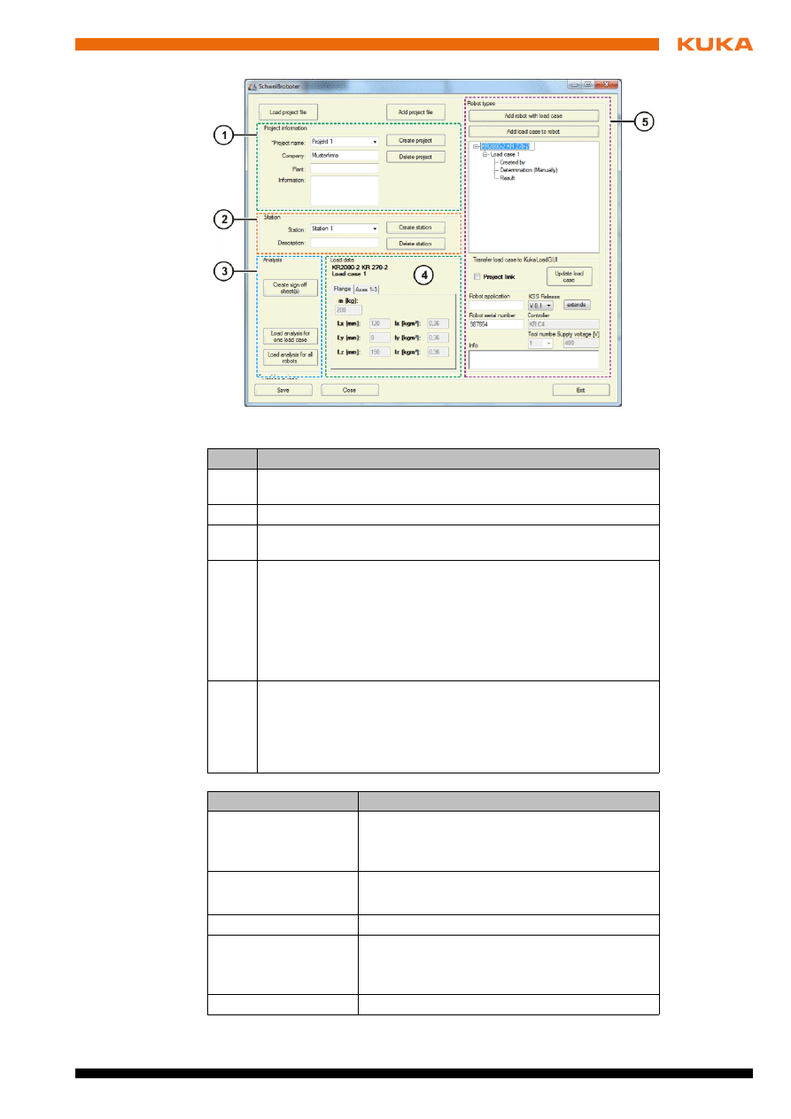
Fig. 4-9: Project window
Item
Description
1
In the Project information area, information about the project
can be entered.
2
In the Station area, information about the station can be entered.
3
In the Analysis area, a load analysis can be carried out for one or
more load cases, and sign-off sheets can be created.
4
In the Load data area, the selected robot and its load case are
shown. The payload and supplementary loads are displayed sep-
arately.
Mass
Distance to the center of gravity (L
x
, L
y
, L
z
)
Mass moments of inertia at the center of gravity (I
x
, I
y
, I
z
)
5
In the Robot types area, robots and load cases can be added. A
link can be established between the project window and the
graphical user interface. Information is displayed about the proj-
ect; some of this can be changed.
(
>>>
4.3.1 "“Robot types” area (KUKA.Load Pro)" Page 22)
Button
Description
Load project file
Load a project file.
Note
: The previously loaded project file will be
closed.
Add
project file
Merge project files.
The Project merge window is opened.
Create project
Create a new project.
Delete project
Delete the selected project.
Note
: Only possible if at least one other project
has been created in the project file.
Create station
Create a new station.
22 / 47
Issued: 06.05.2013 Version: KUKA.Load 5.0 V2 en (PDF)
KUKA.Load 5.0 KUKA.Load Pro 5.0
4.3.1
“Robot types” area (KUKA.Load Pro)
Delete station
Delete the selected station.
Note
: If only one station has been created, the
higher-level project is deleted.
Create sign-off
sheet(s)
Create one or more sign-off sheets.
The Sign-Off Sheet window is displayed.
Load analysis for
one load case
Carry out a load analysis for the selected robot
and its load case.
Note
: The result is displayed in the project infor-
mation in the Robot types area.
Load analysis for all
robots
Carry out a load analysis for all robots and their
load cases which exist in the loaded project file.
Add robot with load
case
Transfer a robot selected on the KukaLoadGUI,
together with its current load case, to the station
of the current project.
Add load case to robot
Add a further load case to a robot.
Update load case
Transfer load data for the selected load case to
the project.
Advanced
Displays additional KSS releases.
Save
Save the project file.
Close
Close the project window.
Note
: The project file remains loaded.
Exit
Close the project.
The project window and project file are closed.
Button
Description
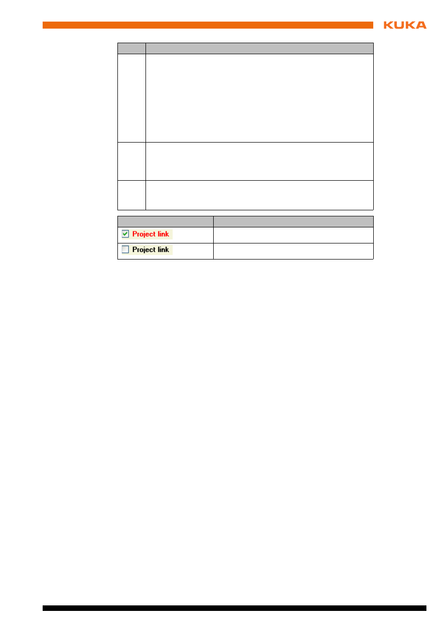
Fig. 4-10: “Robot types” area
Issued: 06.05.2013 Version: KUKA.Load 5.0 V2 en (PDF)
4 Graphical user interface
Item
Description
1
In this box, the robots are shown with their load cases in a tree
structure. Each load case is assigned an originator, determination
and result. Right-clicking on Determination allows selection of
the method of determination for the load data.
With the exception of determination and result, all the elements
can be renamed by double-clicking. Robots and load cases can
be deleted by right-clicking on the robot or load case and selecting
Delete
. If a robot is assigned only one load case, the robot is also
deleted together with the load case.
2
In the area Transfer load case to KukaLoadGUI, a link can be
established between the project window and the graphical user
interface. The load case of a robot can be changed on the graphi-
cal user interface.
3
Information about the project is displayed in this area. The robot
application, KSS release and robot serial number can be
changed.
Element
Description
Link is active.
Link is not active.


Issued: 06.05.2013 Version: KUKA.Load 5.0 V2 en (PDF)
5 Operation
5
Operation
5.1
Starting KUKA.Load
Procedure
Under Programs, select Kuka Roboter GmbH > Kuka.Load 5.0 or Ku-
ka.Load Pro 5.0
in the Windows Start menu.
KUKA.Load is opened.
5.2
Changing the unit of measurement
Description
The following measurement systems are available in KUKA.Load:
Metric
Imperial
Procedure
Select the menu sequence Extras > Units and choose the desired mea-
surement system.
5.3
Changing the user interface language
Procedure
Select the menu sequence Extras > Language and select the desired lan-
guage.
5.4
Creating a project file
Description
A project file is used to manage and verify the load data for a number of robots.
The project file is an XML file.
Procedure
1. Select the menu sequence Project > New.
2. In the Create a new project file window, select the file location and enter
a name.
Confirm with Save.
3. A project window with the name of the project file opens.
For example, if the name is “Welding robot”, the project window “Welding
robot” is opened.
4. Enter information in the Project information area and in the Station area.
The Create project button allows a project to be created with associated
information (customer, company, etc.). The Create station button enables
creation of a station with its associated information (station, description).
The names of the projects and the numbers of the stations can be
changed. The buttons Delete project and Delete station can be used to
delete the created projects and stations.
5. Click on the Save button.
The project file is saved.
6. Click on the Close button.
A dialog is displayed, asking if the project should be saved. The project
window is then closed; the project file remains loaded.
5.5
Loading a project file
Precondition
A project file has been created.
Procedure
1. Select the menu sequence Project > Load.
2. Select a saved project file and confirm with Open.
26 / 47
Issued: 06.05.2013 Version: KUKA.Load 5.0 V2 en (PDF)
KUKA.Load 5.0 KUKA.Load Pro 5.0
The project file is loaded.
5.6
Opening a project file
Precondition
A project file has been created.
Procedure
1. Select the menu sequence Project > Load.
2. Select a saved project file and confirm with Open.
The project file is loaded.
3. Select the menu sequence Project > Open.
Alternative
1. Select the menu sequence Project > Load and open.
2. Select a saved project file and confirm with Open.
The project file is loaded and opened.
5.7
Performing a load analysis
Precondition
Load data are known.
Procedure
1. Select a robot in the Robot type area.
The displayed robot types can be filtered in the Preselection area.
2. Enter the payload and supplementary loads in the Load data area.
3. Click on the Load analysis button.
The results and the static evaluation are shown in the Load analysis area.
If more than one component is mounted on the flange at the same
time, use the Add tool data button (
>>>
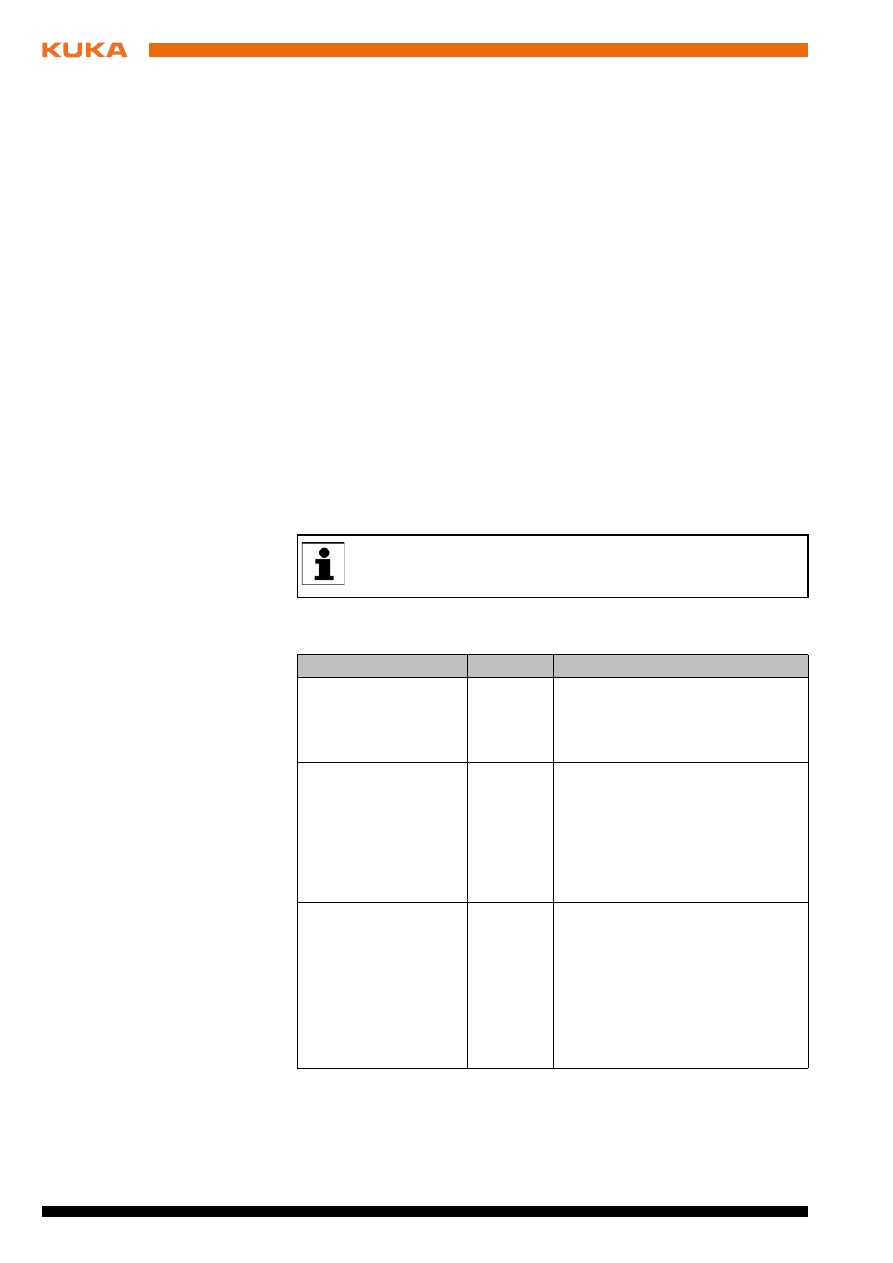
Result message
Display
Description
The robot type is
released
Green
The selected robot type is suitable
for the specified load case.
The robot axes have statically and
dynamically optimal loadings.
Caution: Valid only in
palletizing mode!
The robot type is
released
Green
The selected robot type is suitable
for the specified load case. The
release is only valid, however, if the
robot is operated in palletizing
mode.
Note
: This result message is only
used in KUKA.Load Pro.
The robot type is
released
Cycle time analysis
recommended
Yellow
The selected robot type is suitable
for the specified load case.
The robot axes have statically and
dynamically optimal loadings.
The maximum axis velocities rela-
tive to the attainable velocities at
nominal load are shown on the
Velocity
tab.
Issued: 06.05.2013 Version: KUKA.Load 5.0 V2 en (PDF)
5 Operation
4. If the selected robot type is not suitable:
Select a different robot type in the Robot type area.
5. Click on the Load analysis button to verify the load data.
5.8
Using the “Add tool data” button
Description
The Add tool data button allows several loads to be added together to make
a total load. For this, the load data for each component are entered separately.
Procedure
1. In the Load data area, click on the Add tool data button.
The Summation Tool window is opened.
Caution: Valid only in
palletizing mode!
The robot type is
released
Cycle time analysis
recommended
Yellow
The selected robot type is suitable
for the specified load case. The
release is only valid, however, if the
robot is operated in palletizing
mode.
The robot axes have statically and
dynamically optimal loadings.
The maximum axis velocities rela-
tive to the attainable velocities at
nominal load are shown on the
Velocity
tab.
Note
: This result message is only
used in KUKA.Load Pro.
Robot is statically
OK
Robot is dynami-
cally overloaded
Red
The selected robot type is not suit-
able for the specified load case.
Robot is dynami-
cally overloaded
Robot is statically
overloaded
Red
Robot is statically
overloaded
Red
If the results obtained continue to be negative, please consult KUKA
Roboter GmbH.
Result message
Display
Description
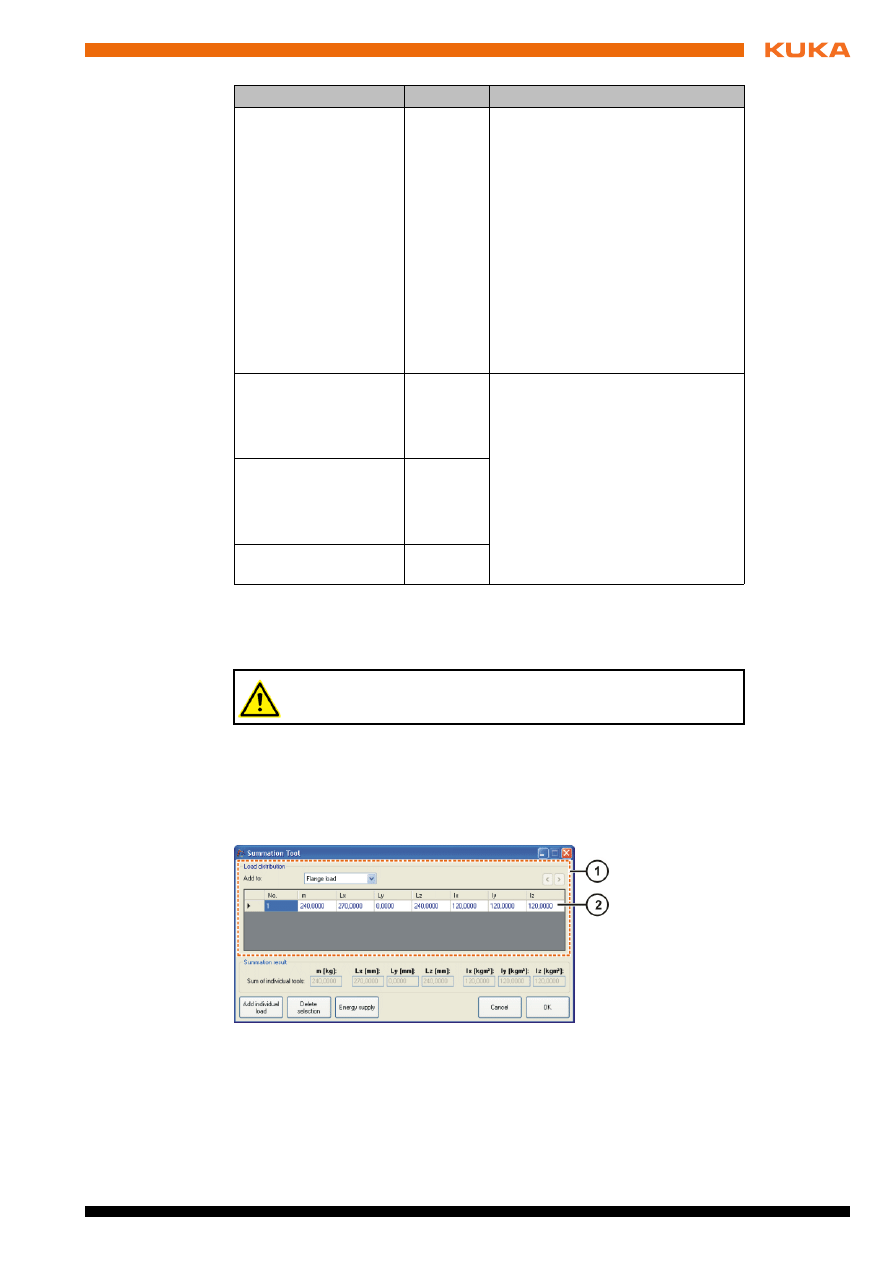
Fig. 5-1: “Summation Tool” window
1
“Load distribution” area
2
Load components
28 / 47
Issued: 06.05.2013 Version: KUKA.Load 5.0 V2 en (PDF)
KUKA.Load 5.0 KUKA.Load Pro 5.0
2. In the Load distribution area, specify where the load is located on the ro-
bot using the Add to box.
3. Enter the load data of the components.
4. To specify values for further components, click on the Add individual
load
button and enter the load data.
The sum of the currently specified loads is displayed in the Sum of indi-
vidual tools
area.
5. To select an energy supply system, click on the Energy supply button.
The Energy supply system window is opened. Select the application and
configuration of the energy supply system.
6. Confirm the entries made by pressing OK.
Transfer the payload and supplementary loads to the KukaLoadGUI win-
dow.
5.9
Searching for a robot
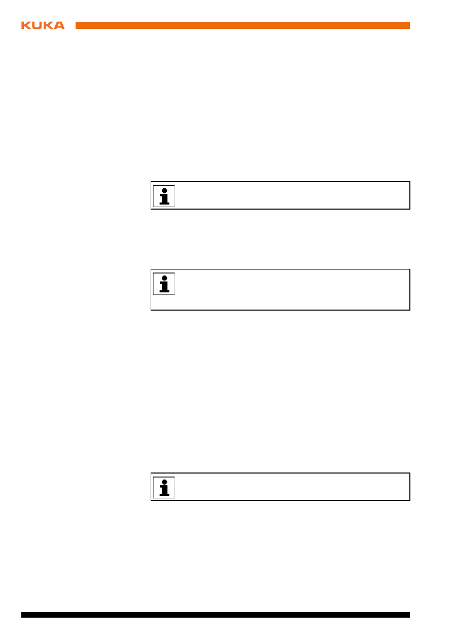
Description
Potentially suitable robots for the specified load case are displayed and 2 ro-
bots are recommended.
Procedure
1. Enter the payload and supplementary loads in the Load data area.
The range of robot types can be restricted in the Preselection area.
2. Click on the Robot search button.
3. After the search, the Load analysis area changes into the Robot search
area.
Only robots which are relevant for this load case are now displayed in the
Robot type
area.
in the Robot search area, 2 recommended robots and their static evalua-
tions are displayed for the specified load case.
4. The recommended robots are displayed simultaneously on the following
tabs, where they can be compared:
Payload diagram
Static
Dynamic
To delete a supplementary load, select the relevant line and click on
the Delete selection button.
The robots are recommended on the basis of their suitability for the
specified load data. Additional requirements arising from the applica-
tion cannot be taken into account here. More detailed guidance is of-
fered by KUKA Service.
The tabs are locked if a load case is changed after the search. Click-
ing on the Robot search button makes the tabs accessible again.
Issued: 06.05.2013 Version: KUKA.Load 5.0 V2 en (PDF)
5 Operation
5.10
Comparing robots
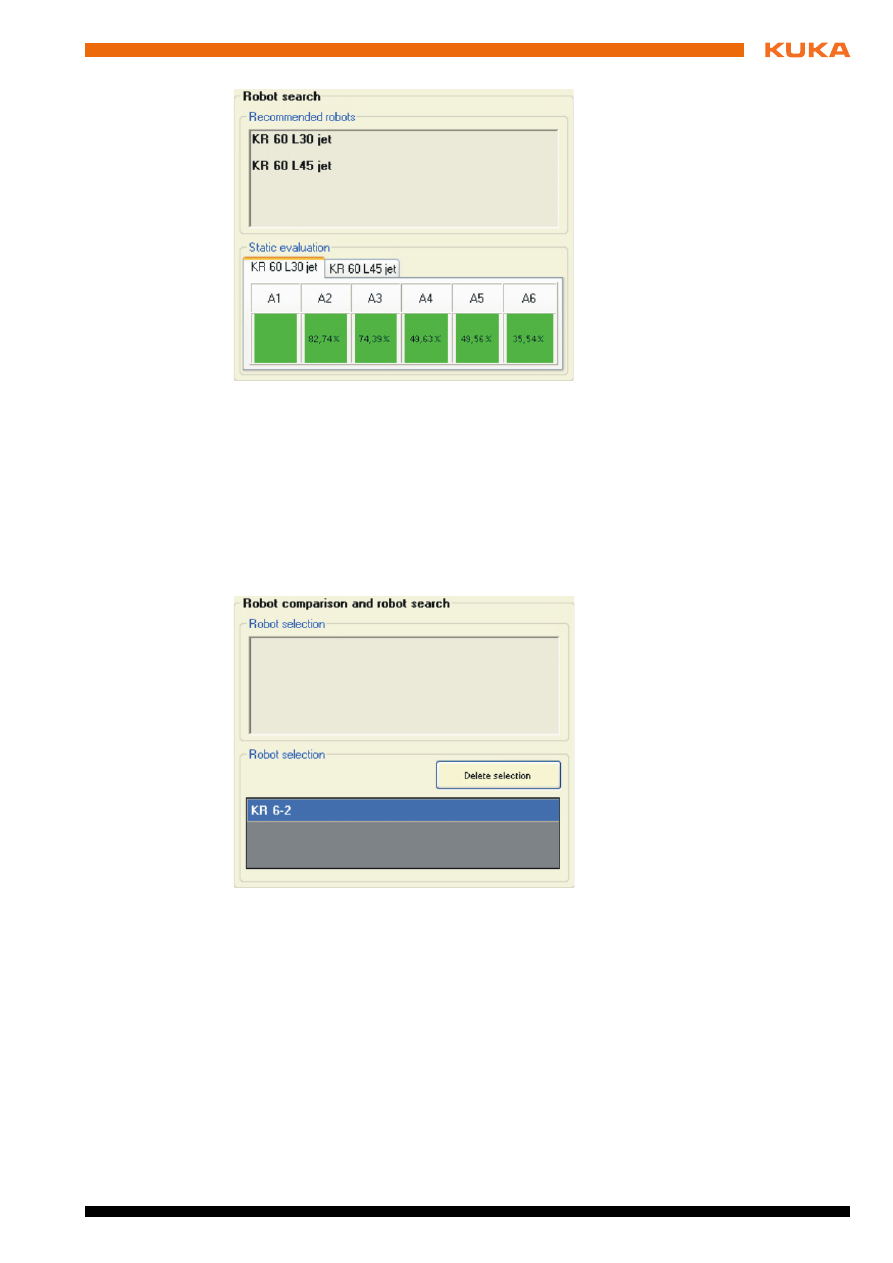
Procedure
1. Click on the Robot comparison button.
Next to the button, a message is displayed, indicating that robot compari-
son is activated.
The Load analysis area changes into the Robot comparison area.
2. Select up to 3 robots in the Robot type area.
The robot selection is displayed in the Robot comparison area.
3. Enter the load case in the Load data area.
4. To compare the selected robots, click on the Robot comparison button.
The results and the static evaluations are displayed. For an objective com-
parison, the supplementary loads (centers of gravity) of each robot are tak-
en into account.
To delete the selection, move the mouse pointer over the Robot type area.
The Delete selection button is then displayed.
Fig. 5-2: “Robot search” area
Fig. 5-3: “Robot comparison” area
30 / 47
Issued: 06.05.2013 Version: KUKA.Load 5.0 V2 en (PDF)
KUKA.Load 5.0 KUKA.Load Pro 5.0
5.11
Saving the robot in the project
Precondition
A project file is created and loaded or open.
Procedure
1. Select a robot in the Robot type area.
The displayed robot types can be filtered in the Preselection area.
2. Enter the values for the payload and supplementary loads in the Load
data
area.
3. Click on the Load analysis button to verify the load data.
The result and the static evaluation are displayed.
4. Click on the
icon in the tool bar.
5. The Enter the password window is opened.
6. Enter the serial number of the selected robot and confirm with OK.
The robot is saved in the selected project and station.
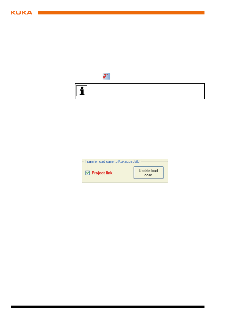
5.12
Changing the saved load case of a robot
Precondition
A project file is loaded and opened.
Procedure
1. In the project window, select a load case in the Robot types display.
2. Activate the Project link check box in the Transfer load case to KukaLo-
adGUI
area.
The robot with its load case is transferred to the graphical user interface
and displayed there.
3. On the graphical user interface, change the load case in the Load data ar-
ea.
4. Optionally, click on the Load analysis button.
5. In the project window, click on the Update load case button.
The changed load case is transferred to the selected project.
6. Save the project in the project window by pressing the Save button.
5.13
Merging 2 project files manually (KUKA.Load Pro)
Precondition
A project file is loaded and opened.
Procedure
1. Click on the Add project file button.
The Project merge window is opened.
2. Click on the Open project file button.
3. Navigate to the directory where the project file is located that is to be
opened.
4. Select the file and confirm with Open. The file is opened in the New proj-
ect file
box. The name of the project file is displayed.
Note the currently selected project (project name, station) shown in
the status bar, to ensure that the robot and load case are saved under
the desired project.
Issued: 06.05.2013 Version: KUKA.Load 5.0 V2 en (PDF)
5 Operation
5. Drag the desired projects, robots, stations or load cases from the tree
structure in the New project file box into the tree structure in the Current
project file
box.
Possible positions for insertion are highlighted in blue when the object is
moved over it with the left-hand mouse button pressed. Robots which dif-
fer in type or name but have the same serial number are highlighted in red
and cannot be merged.
5.14
Merging 2 project files automatically (KUKA.Load Pro)
Description
During automatic merging, the load cases of identical robots are merged irre-
spective of their project and station. Identical robots are robots whose serial
numbers, names and types match. All other robots and their load cases are
merged within their project and station. If a project or station of the same name
is not yet present, the project or station is added; otherwise it is inserted.
If the projects contain robots with the same serial number, but a different type
or name, automatic merging is not possible. An error message is generated
and the operation is aborted.
Precondition
A project file is loaded and opened.
Procedure
1. Click on the Add project file button.
The Project merge window is opened.
2. Click on the Open project file button.
3. Navigate to the directory where the project file is located that is to be
opened.
4. Select the file and confirm with Open. The file is opened in the New proj-
ect file
box. The name of the project file is displayed.
5. Click on the Merge automatically button.
5.15
Merging multiple project files (KUKA.Load Pro)
Description
With automatic merging of multiple project files, the specified directory and all
subdirectories are searched for KUKA.Load project files. These are merged
one after the other with the open project file in the same way as with automatic
merging of 2 project files. Project files that cannot be added automatically are
omitted and listed in a message.
Precondition
The project files that are to be merged are saved in a directory.
A project file is loaded and opened.
Procedure
1. Click on the Add project file button.
The Project merge window is opened.
2. In the Merge multiple project files area, select the directory in which the
project files are saved via ... and confirm with OK.
3. Click on the Merge automatically button.
Names and serial numbers can be changed in the tree structures.
Names and serial numbers can be changed in the tree structures.

32 / 47
Issued: 06.05.2013 Version: KUKA.Load 5.0 V2 en (PDF)
KUKA.Load 5.0 KUKA.Load Pro 5.0
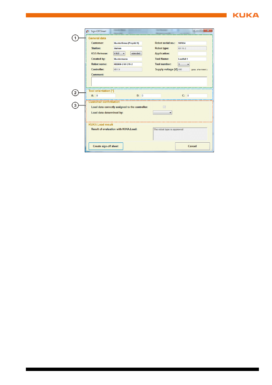
5.16
Creating a sign-off sheet
Precondition
The robot and load data have been entered.
A load analysis has been performed.
or
A project file has been created and opened.
The load case is selected.
Procedure
1. Select the menu sequence File > Create sign-off sheet.
or
In the project window, click on the Create sign-off sheet button.
The Sign-Off Sheet window is opened.
2. In the General data area, enter the customer, the station, the KSS re-
lease, the creator and the robot serial number.
If the following details have already been entered in the open project,
these are transferred to the Sign-Off Sheet window:
Customer
Station
KSS Release (KUKA.Load Pro only)
Further KSS releases can be displayed by pressing the Advanced
button. If a different release is selected, the controller may change if
the robot is supported with this voltage and controller.
Created by
Robot name
Controller (KUKA.Load Pro only)
Robot serial no.
Robot type
Application
Tool name
Tool number (KUKA.Load Pro only)
Supply voltage (KUKA.Load Pro only)
Determination of the load data (KUKA.Load Pro only)
3. The orientation of the coordinate system for the principal moments of iner-
tia at the center of gravity can be entered in the Tool orientation [°] area.
4. Fill out the following box in the Customer confirmation area:
Load data determined by
:
CAD
Manually
LDD (load data determination)
5. Click on the Create sign-off sheet button to create and open the sign-off
sheet.
The customer confirms via the sign-off sheet that the load data have been
correctly assigned to the controller.
Comments should only be written in German or English.
Issued: 06.05.2013 Version: KUKA.Load 5.0 V2 en (PDF)
5 Operation
Fig. 5-4: Sign-Off Sheet window
1
General data
area
2
Tool orientation [°]
area
3
Customer confirmation
area
34 / 47
Issued: 06.05.2013 Version: KUKA.Load 5.0 V2 en (PDF)
KUKA.Load 5.0 KUKA.Load Pro 5.0
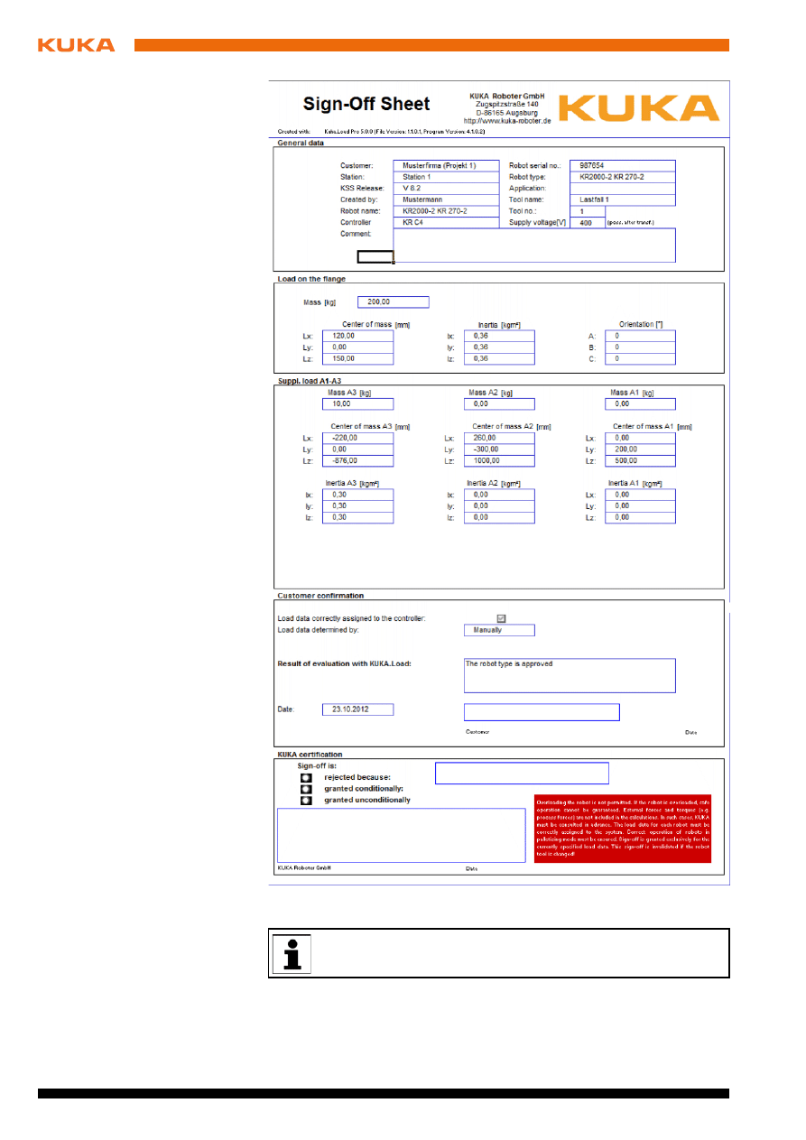
5.17
Creating multiple sign-off sheets simultaneously (KUKA.Load Pro)
Precondition
A project file has been created and opened.
Fig. 5-5: Sign-off sheet (example)
When submitting sign-off sheets for checking by KUKA Roboter
GmbH, any project files (*.xml) must also be included.

Issued: 06.05.2013 Version: KUKA.Load 5.0 V2 en (PDF)
5 Operation
No load case is selected.
Procedure
1. In the project window, click on the Create sign-off sheet(s) button.
The Select the load cases window is opened.
2. Select the load cases for which sign-off sheets are to be created and con-
firm with Start.
A Sign-Off Sheet window is opened for each load case.
3. To save the sign-off sheets, select the relevant directory in the File path
area via ..., and confirm with OK. Confirm the selection with Start.
If all the necessary information for a load case has already been entered
in the project window, the sign-off sheet is automatically saved to the spec-
ified directory. The Sign-Off Sheet window is not displayed in this case.
The necessary information includes the creator and the KSS release.


Issued: 06.05.2013 Version: KUKA.Load 5.0 V2 en (PDF)
6 KUKA Service
6
KUKA Service
6.1
Requesting support
Introduction
The KUKA Roboter GmbH documentation offers information on operation and
provides assistance with troubleshooting. For further assistance, please con-
tact your local KUKA subsidiary.
Information
The following information is required for processing a support request:
Model and serial number of the robot
Model and serial number of the controller
Model and serial number of the linear unit (if applicable)
Model and serial number of the energy supply system (if applicable)
Version of the KUKA System Software
Optional software or modifications
Archive of the software
For KUKA System Software V8: instead of a conventional archive, gener-
ate the special data package for fault analysis (via KrcDiag).
Application used
Any external axes used
Description of the problem, duration and frequency of the fault
6.2
KUKA Customer Support
Availability
KUKA Customer Support is available in many countries. Please do not hesi-
tate to contact us if you have any questions.
Argentina
Ruben Costantini S.A. (Agency)
Luis Angel Huergo 13 20
Parque Industrial
2400 San Francisco (CBA)
Argentina
Tel. +54 3564 421033
Fax +54 3564 428877
ventas@costantini-sa.com
Australia
Headland Machinery Pty. Ltd.
Victoria (Head Office & Showroom)
95 Highbury Road
Burwood
Victoria 31 25
Australia
Tel. +61 3 9244-3500
Fax +61 3 9244-3501
vic@headland.com.au
www.headland.com.au

38 / 47
Issued: 06.05.2013 Version: KUKA.Load 5.0 V2 en (PDF)
KUKA.Load 5.0 KUKA.Load Pro 5.0
Belgium
KUKA Automatisering + Robots N.V.
Centrum Zuid 1031
3530 Houthalen
Belgium
Tel. +32 11 516160
Fax +32 11 526794
info@kuka.be
www.kuka.be
Brazil
KUKA Roboter do Brasil Ltda.
Travessa Claudio Armando, nº 171
Bloco 5 - Galpões 51/52
Bairro Assunção
CEP 09861-7630 São Bernardo do Campo - SP
Brazil
Tel. +55 11 4942-8299
Fax +55 11 2201-7883
info@kuka-roboter.com.br
www.kuka-roboter.com.br
Chile
Robotec S.A. (Agency)
Santiago de Chile
Chile
Tel. +56 2 331-5951
Fax +56 2 331-5952
robotec@robotec.cl
www.robotec.cl
China
KUKA Robotics China Co.,Ltd.
Songjiang Industrial Zone
No. 388 Minshen Road
201612 Shanghai
China
Tel. +86 21 6787-1888
Fax +86 21 6787-1803
www.kuka-robotics.cn
Germany
KUKA Roboter GmbH
Zugspitzstr. 140
86165 Augsburg
Germany
Tel. +49 821 797-4000
Fax +49 821 797-1616
info@kuka-roboter.de
www.kuka-roboter.de

Issued: 06.05.2013 Version: KUKA.Load 5.0 V2 en (PDF)
6 KUKA Service
France
KUKA Automatisme + Robotique SAS
Techvallée
6, Avenue du Parc
91140 Villebon S/Yvette
France
Tel. +33 1 6931660-0
Fax +33 1 6931660-1
commercial@kuka.fr
www.kuka.fr
India
KUKA Robotics India Pvt. Ltd.
Office Number-7, German Centre,
Level 12, Building No. - 9B
DLF Cyber City Phase III
122 002 Gurgaon
Haryana
India
Tel. +91 124 4635774
Fax +91 124 4635773
info@kuka.in
www.kuka.in
Italy
KUKA Roboter Italia S.p.A.
Via Pavia 9/a - int.6
10098 Rivoli (TO)
Italy
Tel. +39 011 959-5013
Fax +39 011 959-5141
kuka@kuka.it
www.kuka.it
Japan
KUKA Robotics Japan K.K.
YBP Technical Center
134 Godo-cho, Hodogaya-ku
Yokohama, Kanagawa
240 0005
Japan
Tel. +81 45 744 7691
Fax +81 45 744 7696
info@kuka.co.jp
Canada
KUKA Robotics Canada Ltd.
6710 Maritz Drive - Unit 4
Mississauga
L5W 0A1
Ontario
Canada
Tel. +1 905 670-8600
Fax +1 905 670-8604
info@kukarobotics.com
www.kuka-robotics.com/canada

40 / 47
Issued: 06.05.2013 Version: KUKA.Load 5.0 V2 en (PDF)
KUKA.Load 5.0 KUKA.Load Pro 5.0
Korea
KUKA Robotics Korea Co. Ltd.
RIT Center 306, Gyeonggi Technopark
1271-11 Sa 3-dong, Sangnok-gu
Ansan City, Gyeonggi Do
426-901
Korea
Tel. +82 31 501-1451
Fax +82 31 501-1461
info@kukakorea.com
Malaysia
KUKA Robot Automation Sdn Bhd
South East Asia Regional Office
No. 24, Jalan TPP 1/10
Taman Industri Puchong
47100 Puchong
Selangor
Malaysia
Tel. +60 3 8061-0613 or -0614
Fax +60 3 8061-7386
info@kuka.com.my
Mexico
KUKA de México S. de R.L. de C.V.
Progreso #8
Col. Centro Industrial Puente de Vigas
Tlalnepantla de Baz
54020 Estado de México
Mexico
Tel. +52 55 5203-8407
Fax +52 55 5203-8148
info@kuka.com.mx
www.kuka-robotics.com/mexico
Norway
KUKA Sveiseanlegg + Roboter
Sentrumsvegen 5
2867 Hov
Norway
Tel. +47 61 18 91 30
Fax +47 61 18 62 00
info@kuka.no
Austria
KUKA Roboter Austria GmbH
Vertriebsbüro Österreich
Regensburger Strasse 9/1
4020 Linz
Austria
Tel. +43 732 784752
Fax +43 732 793880
office@kuka-roboter.at
www.kuka-roboter.at

Issued: 06.05.2013 Version: KUKA.Load 5.0 V2 en (PDF)
6 KUKA Service
Poland
KUKA Roboter Austria GmbH
Spółka z ograniczoną odpowiedzialnością
Oddział w Polsce
Ul. Porcelanowa 10
40-246 Katowice
Poland
Tel. +48 327 30 32 13 or -14
Fax +48 327 30 32 26
ServicePL@kuka-roboter.de
Portugal
KUKA Sistemas de Automatización S.A.
Rua do Alto da Guerra n° 50
Armazém 04
2910 011 Setúbal
Portugal
Tel. +351 265 729780
Fax +351 265 729782
kuka@mail.telepac.pt
Russia
OOO KUKA Robotics Rus
Webnaja ul. 8A
107143 Moskau
Russia
Tel. +7 495 781-31-20
Fax +7 495 781-31-19
kuka-robotics.ru
Sweden
KUKA Svetsanläggningar + Robotar AB
A. Odhners gata 15
421 30 Västra Frölunda
Sweden
Tel. +46 31 7266-200
Fax +46 31 7266-201
info@kuka.se
Switzerland
KUKA Roboter Schweiz AG
Industriestr. 9
5432 Neuenhof
Switzerland
Tel. +41 44 74490-90
Fax +41 44 74490-91
info@kuka-roboter.ch
www.kuka-roboter.ch

42 / 47
Issued: 06.05.2013 Version: KUKA.Load 5.0 V2 en (PDF)
KUKA.Load 5.0 KUKA.Load Pro 5.0
Spain
KUKA Robots IBÉRICA, S.A.
Pol. Industrial
Torrent de la Pastera
Carrer del Bages s/n
08800 Vilanova i la Geltrú (Barcelona)
Spain
Tel. +34 93 8142-353
Fax +34 93 8142-950
Comercial@kuka-e.com
www.kuka-e.com
South Africa
Jendamark Automation LTD (Agency)
76a York Road
North End
6000 Port Elizabeth
South Africa
Tel. +27 41 391 4700
Fax +27 41 373 3869
www.jendamark.co.za
Taiwan
KUKA Robot Automation Taiwan Co., Ltd.
No. 249 Pujong Road
Jungli City, Taoyuan County 320
Taiwan, R. O. C.
Tel. +886 3 4331988
Fax +886 3 4331948
info@kuka.com.tw
www.kuka.com.tw
Thailand
KUKA Robot Automation (M)SdnBhd
Thailand Office
c/o Maccall System Co. Ltd.
49/9-10 Soi Kingkaew 30 Kingkaew Road
Tt. Rachatheva, A. Bangpli
Samutprakarn
10540 Thailand
Tel. +66 2 7502737
Fax +66 2 6612355
atika@ji-net.com
www.kuka-roboter.de
Czech Republic
KUKA Roboter Austria GmbH
Organisation Tschechien und Slowakei
Sezemická 2757/2
193 00 Praha
Horní Počernice
Czech Republic
Tel. +420 22 62 12 27 2
Fax +420 22 62 12 27 0
support@kuka.cz

Issued: 06.05.2013 Version: KUKA.Load 5.0 V2 en (PDF)
6 KUKA Service
Hungary
KUKA Robotics Hungaria Kft.
Fö út 140
2335 Taksony
Hungary
Tel. +36 24 501609
Fax +36 24 477031
info@kuka-robotics.hu
USA
KUKA Robotics Corporation
51870 Shelby Parkway
Shelby Township
48315-1787
Michigan
USA
Tel. +1 866 873-5852
Fax +1 866 329-5852
info@kukarobotics.com
www.kukarobotics.com
UK
KUKA Automation + Robotics
Hereward Rise
Halesowen
B62 8AN
UK
Tel. +44 121 585-0800
Fax +44 121 585-0900
sales@kuka.co.uk


45 / 47
Issued: 06.05.2013 Version: KUKA.Load 5.0 V2 en (PDF)
Index
Index
A
Add load case to robot (button) 19, 22
Add project file (button) 21
Add robot with load case (button) 19, 22
Add tool data (button) 16, 27
Advanced (button) 22
Analysis (area) 18, 21
B
Button, Add tool data 27
Buttons 14, 16
C
Center of gravity 9
Close (button) 22
Create project (button) 19, 21
Create sign-off sheet (button) 19
Create sign-off sheet(s) (button) 22
Create station (button) 19, 21
Creating a project file 25
D
Delete project (button) 19, 21
Delete station (button) 19, 22
Dynamic loading 6
Dynamic overloading 6
Dynamic overloading of the robot 9
E
Energy supply (button) 16
Exit (button) 19, 22
G
Graphical user interface 13
Graphical user interface KukaLoadGUI 13
Graphics card 11
I
Imperial measurement system 6
Installation 11
Installing KUKA.Load 11
Introduction 5
L
Language, changing 25
Load analysis (area) 14
Load analysis (button) 15, 19
Load analysis for all robots (button) 22
Load analysis for one load case (button) 22
Load analysis, performing 26
Load case 6
Load data (area) 14, 19, 21
Load project file (button) 21
Loads on the robot 8
M
Mass 9
Mass moments of inertia 9
Merging multiple project files (KUKA.Load Pro)
31
Merging project files automatically (KUKA.Load
Pro) 31
Merging project files manually (KUKA.Load Pro)
30
Metric measurement system 6
N
Nom. values (button) 16
Nom. values of all suppl. loads (button) 16
P
Payloads 8
Preselection (area) 14
Processor 11
Product description 7
Project file, loading 25
Project information (area) 18, 21
Project window 18
Project window (KUKA.Load Pro) 20
R
RAM 11
Robot comparison 29
Robot comparison (button) 15
Robot search 28
Robot search (button) 14
Robot type (area) 14
Robot types (area) 19, 21
Robots in palletizing mode (KUKA.Load Pro) 10
S
Safety instructions 5
Save (button) 19, 22
Saved robot load case, changing 30
Saving the robot in the project 30
Service, KUKA Roboter 37
Set all nominal values (button) 16
Sign-off sheet, creating 32
Sign-off sheets, creating multiple sheets simul-
taneously (KUKA.Load Pro) 34
Starting, KUKA.Load 25
Static overloading of the robot 9
Station 6
Station (area) 18, 21
Status bar 15
Support request 37
System requirements, KUKA.Load 5.0 11

46 / 47
Issued: 06.05.2013 Version: KUKA.Load 5.0 V2 en (PDF)
KUKA.Load 5.0 KUKA.Load Pro 5.0
T
Tabs 17
Target group 5
Terms used 6
Toolbar 15
Trademarks 5
Training 5
Transfer load case to KukaLoadGUI (area) 20,
23
U
Uninstallation, KUKA.Load 11
Unit of measurement, changing 25
Update load case (button) 19, 22
Updating KUKA.Load 11

Document Outline
- KUKA.Load 5.0 KUKA.Load Pro 5.0
- 1 Introduction
- 2 Product description
- 3 Installation
- 4 Graphical user interface
- 5 Operation
- 5.1 Starting KUKA.Load
- 5.2 Changing the unit of measurement
- 5.3 Changing the user interface language
- 5.4 Creating a project file
- 5.5 Loading a project file
- 5.6 Opening a project file
- 5.7 Performing a load analysis
- 5.8 Using the “Add tool data” button
- 5.9 Searching for a robot
- 5.10 Comparing robots
- 5.11 Saving the robot in the project
- 5.12 Changing the saved load case of a robot
- 5.13 Merging 2 project files manually (KUKA.Load Pro)
- 5.14 Merging 2 project files automatically (KUKA.Load Pro)
- 5.15 Merging multiple project files (KUKA.Load Pro)
- 5.16 Creating a sign-off sheet
- 5.17 Creating multiple sign-off sheets simultaneously (KUKA.Load Pro)
- 6 KUKA Service
- Index
Wyszukiwarka
Podobne podstrony:
KUKA Load 50 fr
KUKA Load 50 es
KUKA Load 50 de
KUKA Load 50 it
KUKA LOAD 32 en
kuka sim V1 1 en
KST KUKA Encryption 12 en
Datasheet BlueSolar charge controller MPPT 75 50 & MPPT 100 50 EN
FIRERAY 5000 50 EN 2 głowice
KST KUKA Encryption 11 en
Manual BlueSolar charge controller MPPT 75 50 EN NL FR DE ES SE A6
KUKA RSI, serSensor kss51 en
KUKA RSI rsi r20 en id 744255 Nieznany
SR 50 2005 en SOLO PAGINA MAPPATURA
więcej podobnych podstron