Packet Tracer Skills Integration Challenge
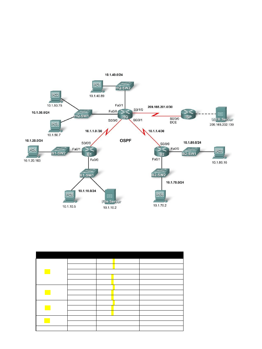
Topology Diagram
Device
Interface
IP Address
Subnet Mask
XX_HQ
S0/0/0
1x.1.1.1
255.255.255.252
S0/0/1
1x.1.1.5
255.255.255.252
S0/1/0
209.165.201.2
255.255.255.252
Fa0/0
1x.1.50.1
255.255.255.0
Fa0/1
1x.1.40.1
255.255.255.0
XX_B1
S0/0/0
1x.1.1.2
255.255.255.252
Fa0/0
1x.1.10.1
255.255.255.0
Fa0/1
1x.1.20.1
255.255.255.0
XX_B2
S0/0/0
1x.1.1.6
255.255.255.252
Fa0/0
1x.1.80.1
255.255.255.0
Fa0/1
1x.1.70.1
255.255.255.0
XX_ISP
S0/0/0
209.165.201.1
255.255.255.252
Fa0/0
209.165.202.129
255.255.255.252
Web Server
NIC
209.165.202.130
255.255.255.252

XX
– numer indeksu
X
– numer z listy grupy
Learning Objectives
•
Configure devices
•
Configure default routing.
•
Configure OSPF routing.
•
Implement and verify multiple ACL security policies.
Introduction
The user EXEC password is cisco, and the privileged EXEC password is class.
Task 1:
•
Configure hostnames to match the topology diagram.
•
Disable DNS lookup.
•
Configure an encrypted privileged EXEC password of class.
•
Configure a message-of-the-day (
imię_nazwisko) banner.
•
Configure a password of cisco for console connections.
•
Configure a password of cisco for vty connections.
•
Configure IP addresses and masks on all devices. Set the clock rate to 64000.
Task 2: Configure Default Routing
Step 1. Configure default routing from HQ to ISP.
Configure a default route on HQ to send all default traffic to ISP.
Step 2. Test connectivity to Web Server.
HQ should be able to successfully ping Web Server at 209.165.202.130 as long as the ping is sourced from the Serial0/1/0
interface.
Task 3: Configure OSPF Routing
Step 1. Configure OSPF on HQ.
•
Configure OSPF using the process ID 1.
•
Advertise all subnets except the 209.165.201.0 network.
•
Propagate the default route to OSPF neighbors.
•
Disable OSPF updates to ISP and to the HQ LANs.
Step 2. Configure OSPF on B1 and B2.
•
Configure OSPF using the process ID 1.
•
On each router, configure the appropriate subnets.
•
Disable OSPF updates to the LANs.
Step 3. Test connectivity throughout the network.
The network should now have full end-to-end connectivity. All devices should be able to successfully ping all other devices,
including Web Server at 209.165.202.130.
Task 4: Implement Multiple ACL Security Policies
Step 1. Implement security policy number 1.
Block the 1x.1.10.0 network from accessing the 1x.1.40.0 network. All other access to 1x.1.40.0 is allowed. Configure the
ACL on HQ using ACL number 20.
•
Use a standard or extended ACL? _______________
•
Apply the ACL to which interface? _______________
•
Apply the ACL in which direction? _______________

Step 2. Verify that security policy number 1 is implemented.
A ping from PC5 to PC1 should fail.
Step 3. Implement security policy number 2.
Host 1x.1.10.5 is not allowed to access host 1x.1.50.7. All other hosts are allowed to access 1x.1.50.7. Configure the ACL on
B1 using ACL number 125.
•
Use a standard or extended ACL? _______________
•
Apply the ACL to which interface? _______________
•
Apply the ACL in which direction? _______________
Step 4. Verify that security policy number 2 is implemented.
A ping from PC5 to PC3 should fail.
Hosts 1x.1.50.1 through 1x.1.50.63 are not allowed web access to Intranet server at 1x.1.80.16. All other access is allowed.
Configure the ACL on the appropriate router and use ACL number 121.
•
Use a standard or extended ACL? _______________
•
Configure the ACL on which router? ______________
•
Apply the ACL to which interface? _______________
•
Apply the ACL in which direction? _______________
Step 5. Verify that security policy number 3 is implemented.
To test this policy, click PC3, then the Desktop tab, and then Web Browser. For the URL, type in the IP address for the Intranet
server, 1x.1.80.16, and press Enter. After a few seconds, you should receive a Request Timeout message. PC2 and any other
PC in the network should be able to access the Intranet server.
Step 6. Implement security policy number 4.
Use the name NO_FTP to configure a named ACL that blocks the 1x.1.70.0/24 network from accessing FTP services (port 21) on
the file server at 1x.1.10.2. All other access should be allowed. Note: Names are case-sensitive.
•
Use a standard or extended ACL? _______________
•
Configure the ACL on which router? ______________
•
Apply the ACL to which interface? _______________
•
Apply the ACL in which direction? _______________
Step 7. Implement security policy number 5.
Since ISP represents connectivity to the Internet, configure a named ACL called FIREWALL in the following order:
1. Allow only inbound ping replies from ISP and any source beyond ISP.
2. Allow only established TCP sessions from ISP and any source beyond ISP.
3. Explicitly block all other inbound access from ISP and any source beyond ISP.
•
Use a standard or extended ACL? _______________
•
Configure the ACL on which router? ______________
•
Apply the ACL to which interface? _______________
•
Apply the ACL in which direction? _______________
Step 8. Verify that security policy number 5 is implemented.
To test this policy, any PC should be able to ping ISP or Web Server. However, neither ISP nor Web Server should be able
to ping HQ or any other device behind the FIREWALL ACL.
Wyszukiwarka
Podobne podstrony:
lab 7, 9.4.1.2 Packet Tracer - Skills Integration Challenge Instructions
11 6 1 2 Packet Tracer Skills Integration Challenge Instructions
Lab 5, 6.5.1.2 Packet Tracer Skills Integration Challenge Instructions
9 4 1 2 Packet Tracer Skills Integration Challenge Instructions
2 4 1 2 Packet Tracer Skills Integration Challenge Instructions
8 4 1 2 Packet Tracer Skills Integration Challenge Instructions
6 5 1 2 Packet Tracer Skills Integration Challenge Instructions
8 4 1 2 Packet Tracer Skills Integration Challenge Instructions
6 4 1 2 Packet Tracer Configure Initial Router Settings Instructions
5 3 3 5 Packet Tracer Configure Layer 3 Switches Instructions
3 3 3 3 Packet Tracer Explore a Network Instructions
8 3 2 6 Packet Tracer Pinging and Tracing to Test the Path Instructions
9 2 1 5 Packet Tracer ?signing and Implementing a VLSM?dressing Scheme Instruct
Packet Tracer CLI Info ACL
7 3 1 2 Packet Tracer Simulation Exploration of TCP and UDP Instructions
11 3 3 4 Packet Tracer Using Show Commands Instructions
Lab 6, 10.2.2.8 Packet Tracer - DNS and DHCP Instructions
4 2 4 5 Packet Tracer Connecting a Wired and Wireless LAN Instructions
2 1 4 8 Packet Tracer Navigating the IOS Instructions
więcej podobnych podstron