
APPENDIX
Return To Main Table of Contents
GENERAL . . . . . . . . . . . . . . . . . . . . . . . . . . . . . . . . . . . . . . . . . . . . . .
TROUBLESHOOTING PROCEDURES . . . . . . . . . . . . . . . . . . . 8
. . . . . . . . . . . . . . . . . . . . . . . .
IGNITION SYSTEM . . . . . . . . . . . . . . . . . . . . . . . . . . . . . . . . . . . .
CHARGING SYSTEM . . . . . . . . . . . . . . . . . . . . . . . . . . . . . . . . . .
STARTING SYSTEM (A/T) . . . . . . . . . . . . . . . . . . . . . . . . . . . . . 18
STARTING SYSTEM (M/T) . . . . . . . . . . . . . . . . . . . . . . . . . . . .
COOLING SYSTEM . . . . . . . . . . . . . . . . . . . . . . . . . . . . . . . . . . . .
M.P.I. SYSTEM . . . . . . . . . . . . . . . . . . . . . . . . . . . . . . . . . . . . . . . .
F.B.C. SYSTEM . . . . . . . . . . . . . . . . . . . . . . . . . . . . . . . . . . . . . . .
ELECTRONIC LOCK UP CONTROL (4-SPEED) . . . . . . . . 3 2
AUTOMATIC TRANSAXLE KEY LOCK CONTROL . . . . . 3 6
BRAKE WARNING . . . . . . . . . . . . . . . . . . . . . . . . . . . . . . . . . . . .
HEAD LAMP (U.S.A.) . . . . . . . . . . . . . . . . . . . . . . . . . . . . . . . . .
DAY TIME RUNNING LIGHT (CANADA) . . . . . . . . . . . . . . 4 4
TAIL LAMP (4 DOOR) . . . . . . . . . . . . . . . . . . . . . . . . . . . . . . . . .
TAIL LAMP (3/5 DOOR) . . . . . . . . . . . . . . . . . . . . . . . . . . . . . .
BACK UP LAMP . . . . . . . . . . . . . . . . . . . . . . . . . . . . . . . . . . . . . .
STOP LAMP . . . . . . . . . . . . . . . . . . . . . . . . . . . . . . . . . . . . . . . . . . .
TURN SIGNAL AND HAZARD WARNING LAMP . . . . . . 5 4
FRONT WIPER AND WASHER . . . . . . . . . . . . . . . . . . . . . . . .
REAR WIPER AND WASHER . . . . . . . . . . . . . . . . . . . . . . . . .
ClGARETTE LIGHTER . . . . . . . . . . . . . . . . . . . . . . . . . . . . . . . . .
SUN ROOF . . . . . . . . . . . . . . . . . . . . . . . . . . . . . . . . . . . . . . . . . . . .
TIME AND ALARM CONTROL . . . . . . . . . . . . . . . . . . . . . . . .
TAIL GATE (TRUNK LID) OPENER . . . . . . . . . . . . . . . . . . . .
AIR CONDITIONER (MPI) . . . . . . . . . . . . . . . . . . . . . . . . . . . . .
AIR CONDITIONER (FBC) . . . . . . . . . . . . . . . . . . . . . . . . . . . . .
ELECTRONIC LOCK UP CONTROL (3-SPEED) . . . . . . . . 8 0
WIRING CONNECTORS . . . . . . . . . . . . . . . . . . . . . . . . . . . . . . .
WIRING HARNESS LAYOUT . . . . . . . . . . . . . . . . . . . . . . . . . .
GENERAL
GENERAL
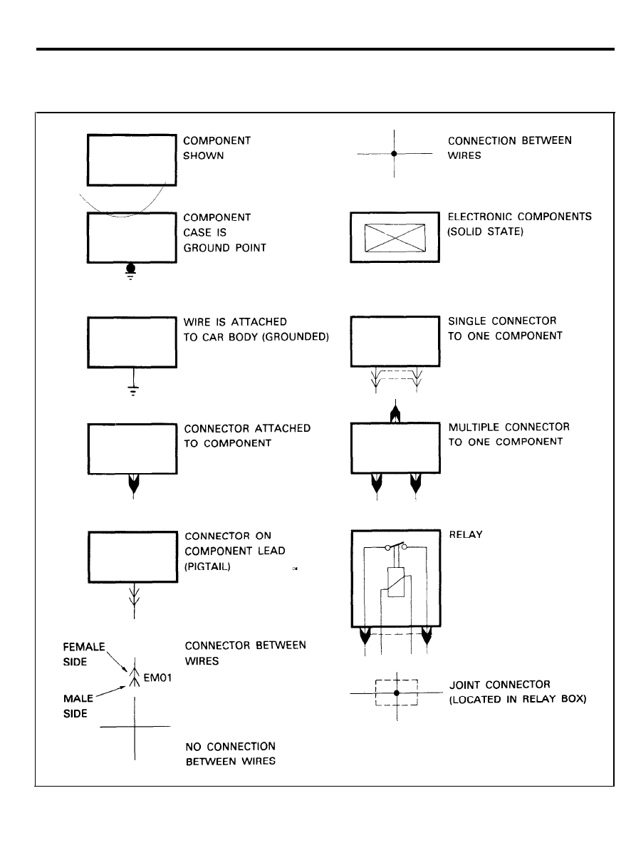
SYMBOLS IN CIRCUIT DIAGRAM
2
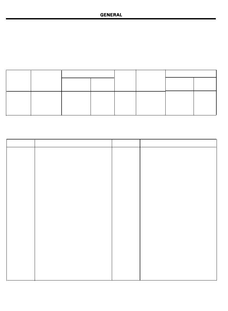
SIZE OF WIRE
Permissible current of each cable is determined by the wire
sectional area which is given at the top of the wiring
identification.
When an optional part is installed determine the electrical load
of the optional part to prevent excessive current flow in the
circuit.
Nominal
size
Permissible current
SAE gage No.
In engine
Nominal
SAE gage No.
Other area
size
compartment
0.3 mm
2
AWG 22
-
5A
2.0 mm
2
AWG 14
0.5 mm
2
AWG 20
7A
13A
3.0 mm
2
AWG 12
0.85 mm
2
AWG 18
9A
17A
5.0 mm
2
AWG 10
1.25 mm
2
AWG 16
12A
22A
ABBREVIATED SYMBOLS
Permissible current
In engine
compartment
Other area
16A
30A
21A
40A
31A
54A
SYMBOL
ACC
AFS
ALTR
ARM
ANT
A / T
A/CON
BATT
COMBI
CONN
DR
ENG
EXT
E.T.R.
ECU
MPI
FRT
G/BOX
GND
H/LAMP
HTD
IGN
ILL
MEANING
SYMBOL
MEANING
Accessory
IND
Indicator
Air flow sensor
ISC
Idle speed control
Alternator
INTERM
Intermittent
Armature
LH
Left hand
Antenna
LR
Left rear
Automatic transaxle
MULTI SW
Multifunction switch
Air conditioner
M / T
Manual transaxle
Battery (B+ : Power supply)
MPS
Motor position sensor
Combination (stop, tail, back-up, and
N.C.
Normal close
turn signal lamp)
N.O.
Normal open
Connector
O/SIDE
Outside
Door
P / W D W
Power window
Engine
RR
Right rear
Extension (wire off main harness)
RH
Right hand
Electronic tuning radio
ST
Start
Electronic control unit
SOL
Solenoid
Multi point fuel injection
S/BELT
Seat belt
Front
SW
Switch
Glove box
TEMP
Temperature
Ground
T/SIG
Turn signal
Head lamp
TDC
Top dead center
Heated
T/LAMP
Taillamp
Ignition (IG : Power supply)
TPS
Throttle position sensor
Illumination
CTS
Coolant
3
GENERAL
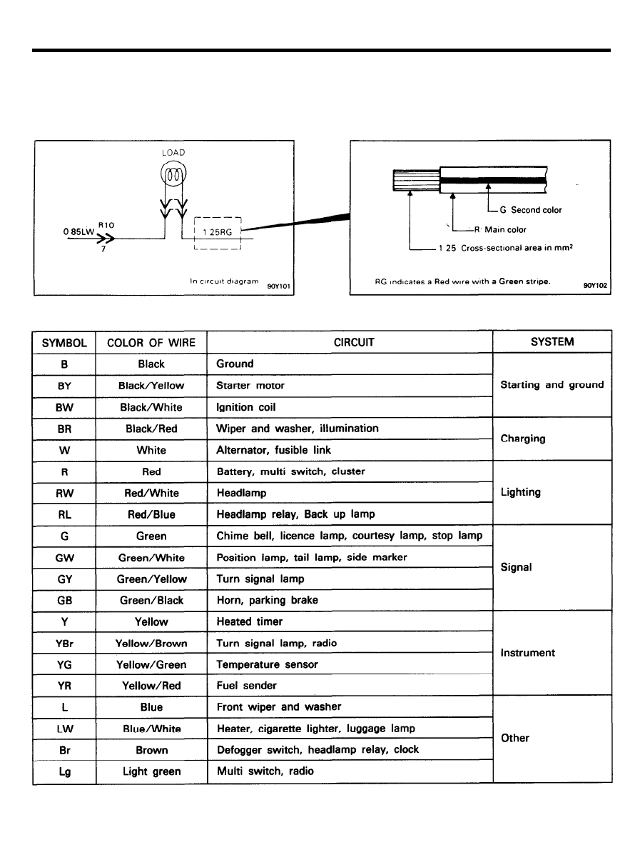
WIRE COLORS IN CIRCUIT DIAGRAM
Colored wire as shown in the following tables are used.
When two colors are used in a wire, the designation of the wire
is as follows.
4
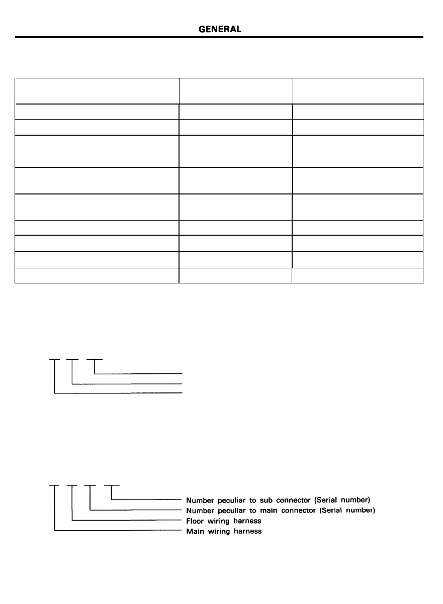
CONNECTOR CLASSIFICATIONS
Electrical wiring connectors are classified according to the wiring parts.
THE PART NAME OF WIRING HARNESS
LOCATION
CONNECTOR IDENTIFICATION
SYMBOL
Main wiring harness
Dash and steering column
Engine wiring harness
Engine compartment
E.C.U. wiring harness
Engine compartment
T/A control wiring harness
Engine compartment
Floor wiring harness
Passenger compartment
Rear floor wiring harness
Luggage compartment
M01 . . . . . . . . . . . . . . . . . . . . . . .
M33
E01 . . . . . . . . . . . . . . . . . . . . . . .
E31
CO1 . . . . . . . . . . . . . . . . . . . . . . . C60
TO1 . . . . . . . . . . . . . . . . . . . . . . .
T20
RO1 . . . . . . . . . . . . . . . . . . . . . . . R54
Crash pad wiring harness
The cluster and switch
Switch extension wiring harness
of instrument
Door wiring harness
Door
Tail gate wiring harness (3/5 door)
Tailgate
Trunk lid wiring harness (4 door)
Trunk lid
I01 . . . . . . . . . . . . . . . . . . . . . . . . . I16
DO1 . . . . . . . . . . . . . . . . . . . . . . . D07
R61 . . . . . . . . . . . . . . . . . . . . . . . R66
R71 . . . . . . . . . . . . . . . . . . . . . . . R74
Roof wiring harness
Roof
M 4 1 . . . . . . . . . . . . . . . . . . . . . . . M 4 4
A connector identification symbol consists of a wiring harness location classification symbol corresponding to each
wiring harness location and number peculiar to the connector.
These connector locations can be found in the WIRING HARNESS LAYOUT.
C
60
-1
Number peculiar to sub connector (Serial number)
Number peculiar to main connector (Serial number)
Symbol indicating wiring harness (E.C.U. wiring harness)
NOTE
Connectors which connect each wiring harness are represented by the following symbols.
For example;
M R 01 -1
5
GENERAL
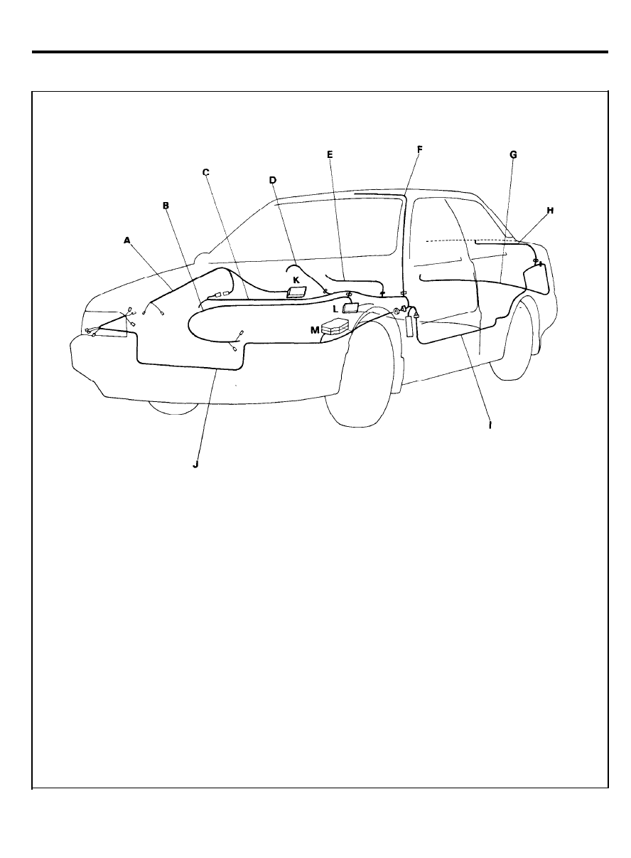
WIRING HARNESS OVERVIEW
A : T/A control wiring harness
B : E.C.U. wiring harness
C : Main wiring harness
D : Switch extension wiring harness
E : Crash pad wiring harness
F : Roof wiring harness
G : Rear floor wiring harness
H : Trunk lid wiring harness
I : Front floor wiring harness
J : Engine wiring harness
K : Transaxle control unit
L : Electronic control unit
M : Relay box (engine compartment)
Note: This illustration shows only the major harness.
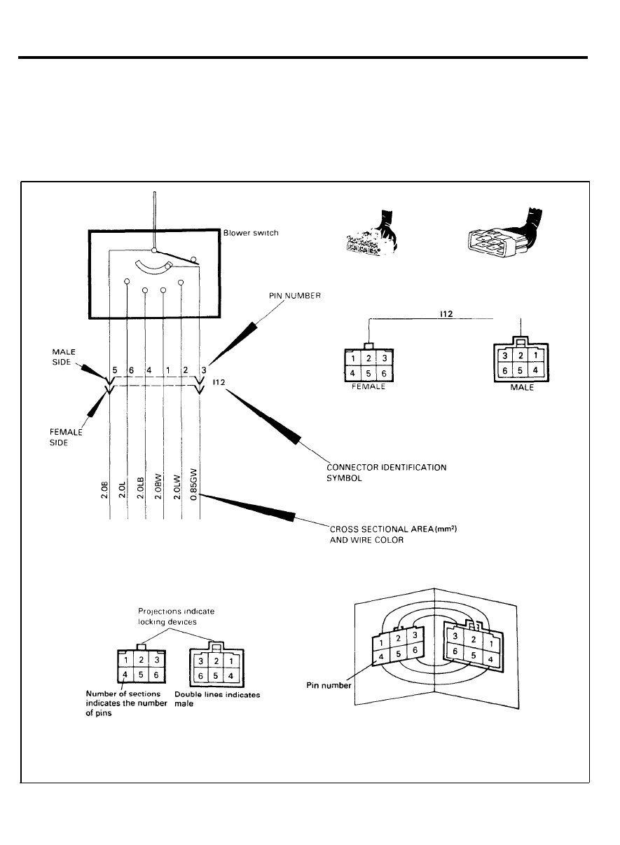
GENERAL
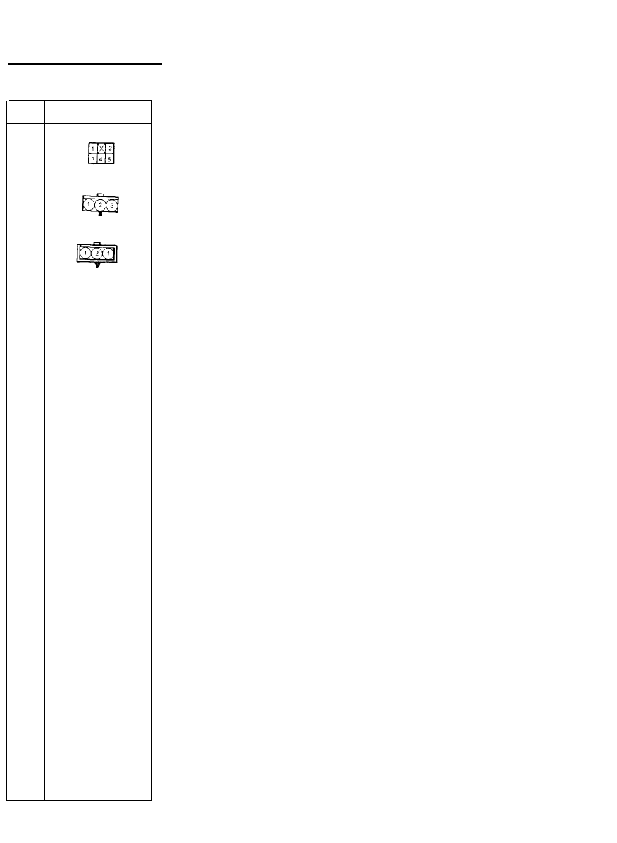
CONNECTOR IDENTIFICATION SYMBOLS
Connectors and connector pin numbers are indicated in each
circuit. Wires and pins of the connectors are also clearly
illustrated.
Identifying the difference between the male or female connector
is determined from the pin type of a connector.
The pin numbers of a pair
of connectors (male and female).
if viewed at their jointing surfaces,
will appear symmetrical.
7
TROUBLESHOOTING PROCEDURES
TROUBLESHOOTING PROCEDURES
TESTING FOR VOLTAGE
1. Connect one lead of a test lamp or voltmeter to a ground.
If you are using a voltmeter, be sure it is the voltmeter’s
negative lead that you have connected to ground.
2. Connect the other lead of the test lamp or voltmeter to a
selected test point (connector or terminal).
3. If the test lamp glows, there is voltage present. If you are
using a voltmeter, note the voltage reading.
A loss of more than 1 volt from specifications indicates a
problem.
8
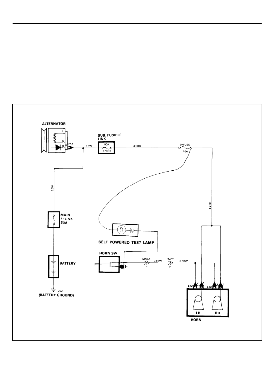
TESTING FOR CONTINUITY
1. Disconnect the battery.
2.
Connect one lead of a self-powered test lamp or ohmmeter
to one end of the part of the circuit you wish to test.
3. Connect the other lead to the other end.
4. If the self-powered test lamp glows, there is continuity.
If you are using an ohmmeter, low or zero resistance means
good continuity.
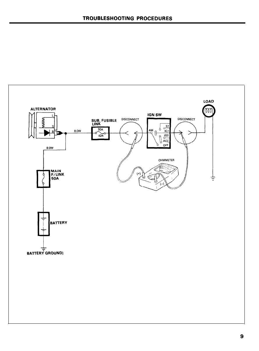
TROUBLESHOOTING PROCEDURES
TESTING FOR SHORT TO GROUND
1.
Remove the blown fuse and disconnect the battery and load.
2. Connect one lead of a self-powered test lamp or an
ohmmeter to the fuse terminal on the load side.
3. Connect the other lead to a ground.
4.
Beginning near the fuse block move the harness from side
to side. Continue this point (about six inches apart) while
watching the test lamp or ohmmeter.
5. When the test lamp glows, or ohmmeter registers, there is
a short to ground in the wiring near that point.
1 0
TROUBLESHOOTING PROCEDURES
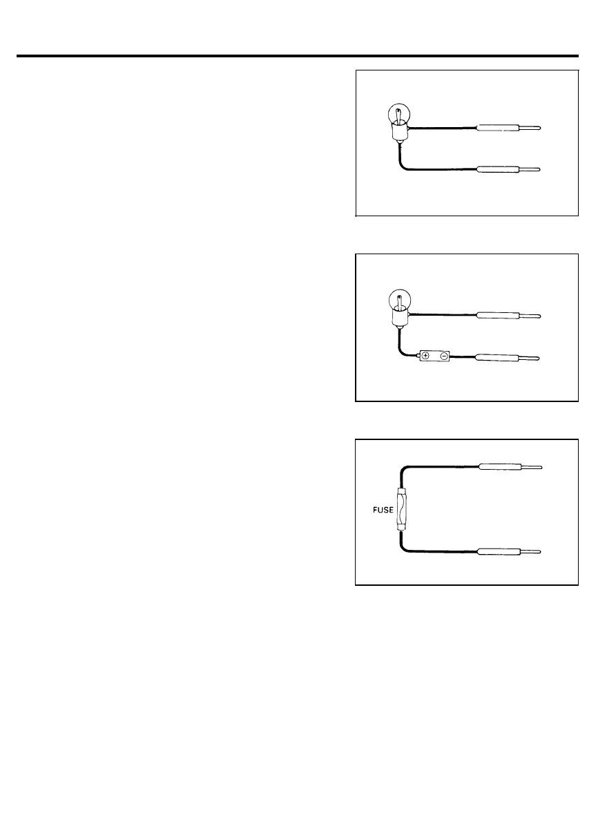
TROUBLESHOOTING TOOLS
1.
A TEST LAMP is made of a 12-Volt bulb with a pair of leads
attached. After grounding one lead, touch the other lead to
various points along the circuit where voltage should be
present. When the bulb glows, there is voltage at the point
being tested.
2. SELF-POWERED TEST LAMP
NOTE
A self-powered test lamp is only used on an unpowered
circuit. Use a self-powered test lamp to check for
continuity.
This tool is made of a bulb, battery and two leads. If the leads
are touched together, the bulb will glow.
3.
A JUMPER WIRE is made of an in-line fuse holder connected
to a set of test leads.
It can be used for by-passing open circuits.
CAUTION
Never use a jumper wire between an electrical source and
ground.
4. A VOLTMETER can be used instead of a test lamp. While
a test lamp shows whether or not voltage is present, a
voltmeter indicates how much voltage is present.
5. A OHMMETER can be used instead of a self-powered test
lamp. The ohmmeter shows how much resistance there is
between two points along a circuit. Low resistance means
good continuity.
6. A DIGITAL MULTIMETER can be used instead of an
ohmmeter, voltmeter or an ammeter.
11
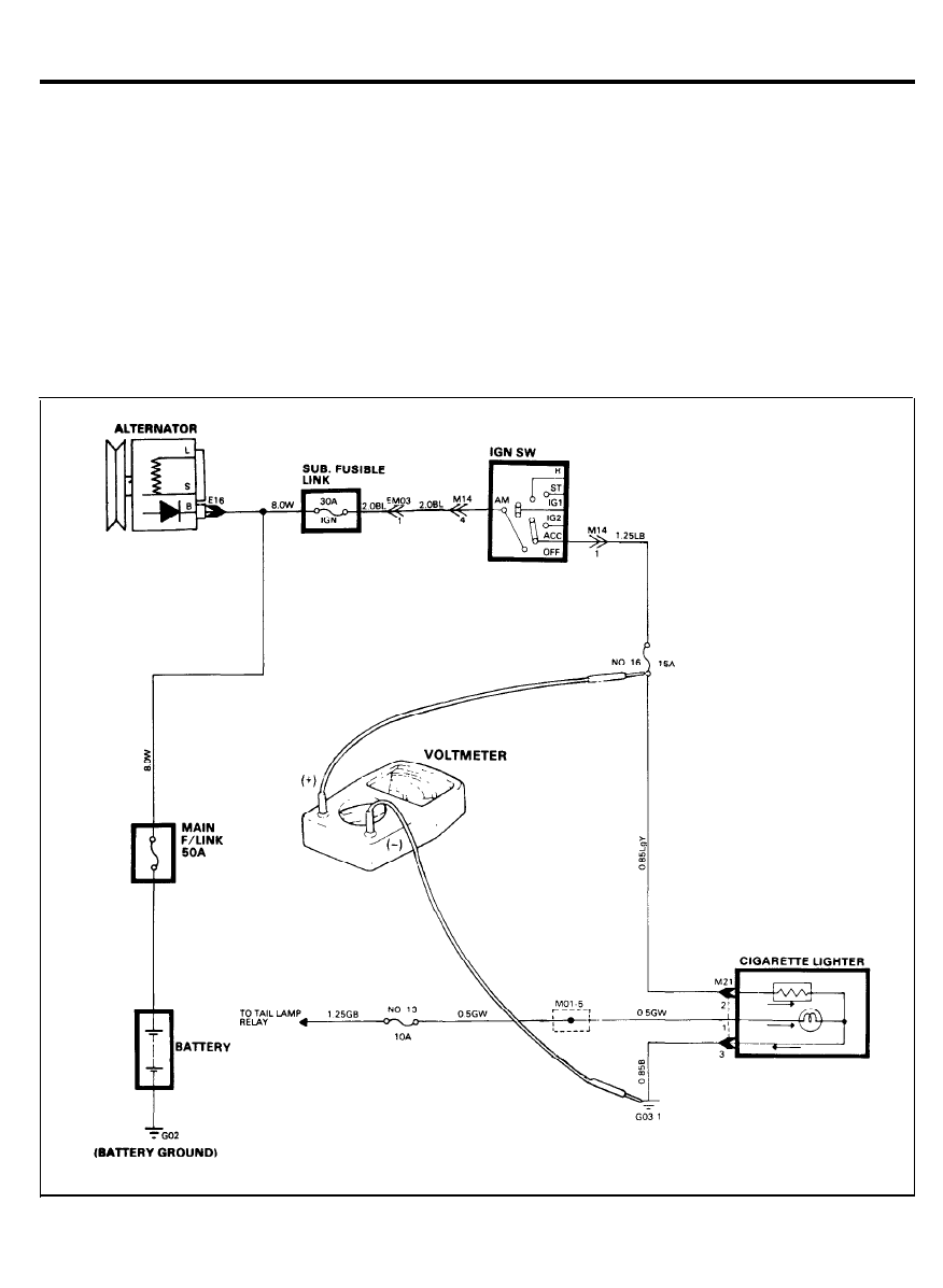
ELECTRICAL POWER SUPPLY
CIRCUIT DIAGRAM
12
ELECTRICAL POWER SUPPLY
CONFIGURATION OF CONNECTORS
M14
E06
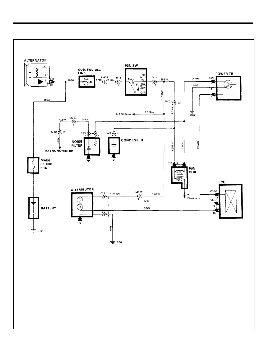
IGNITION SYSTEM
CIRCUIT DIAGRAM
14
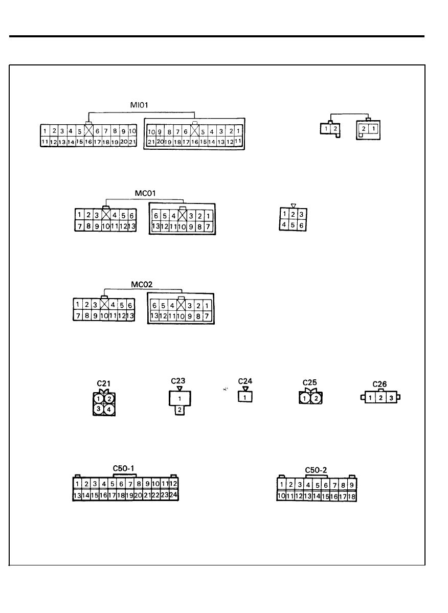
IGNITION SYSTEM
CONFIGURATION OF CONNECTORS
M14
EM03
15
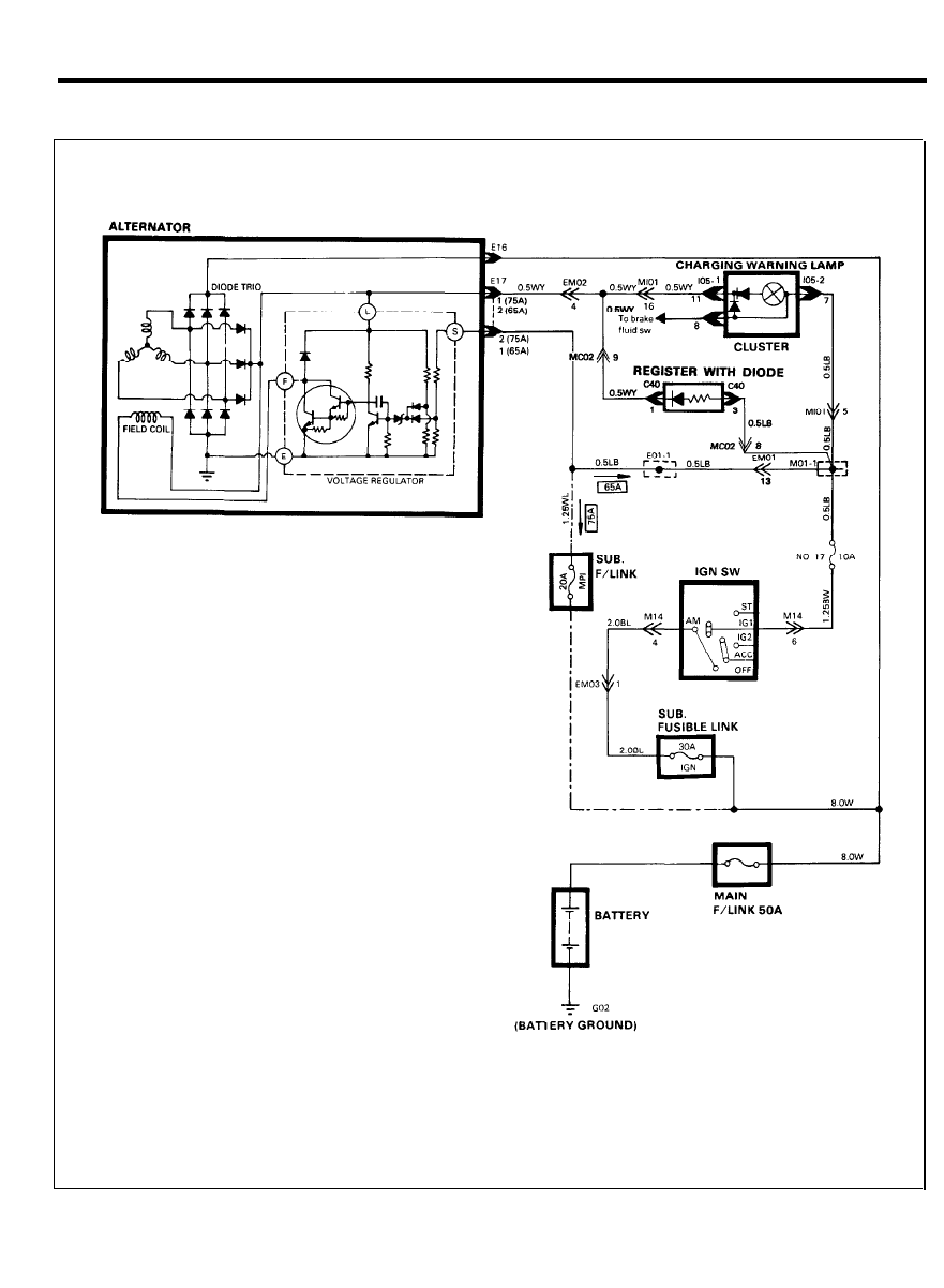
CHARGING SYSTEM
CIRCUIT DIAGRAM
16
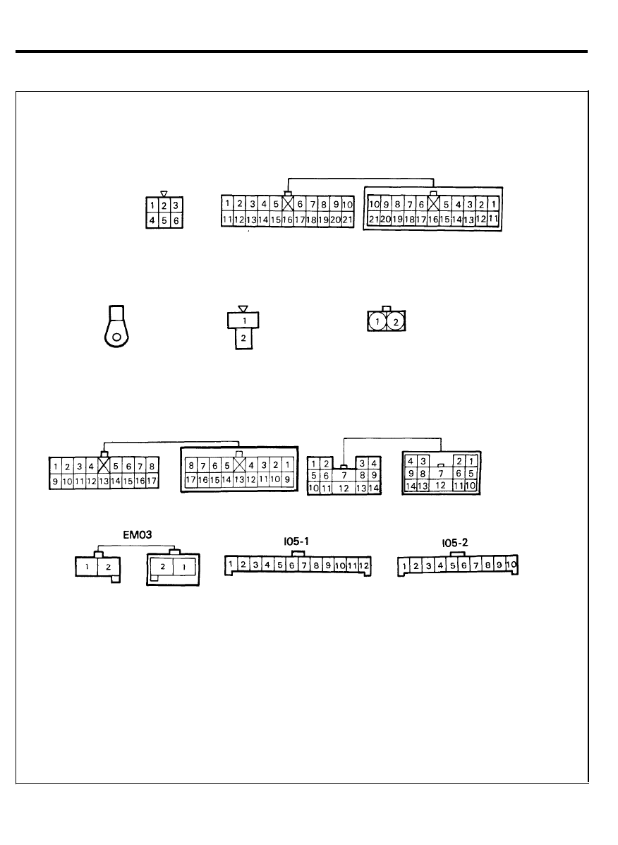
CHARGING SYSTEM
CONFIGURATION OF CONNECTORS
M14
E16
EM01
Ml01
E17
(For 65A alternator)
E17
(For 75A alternator)
EM02
17
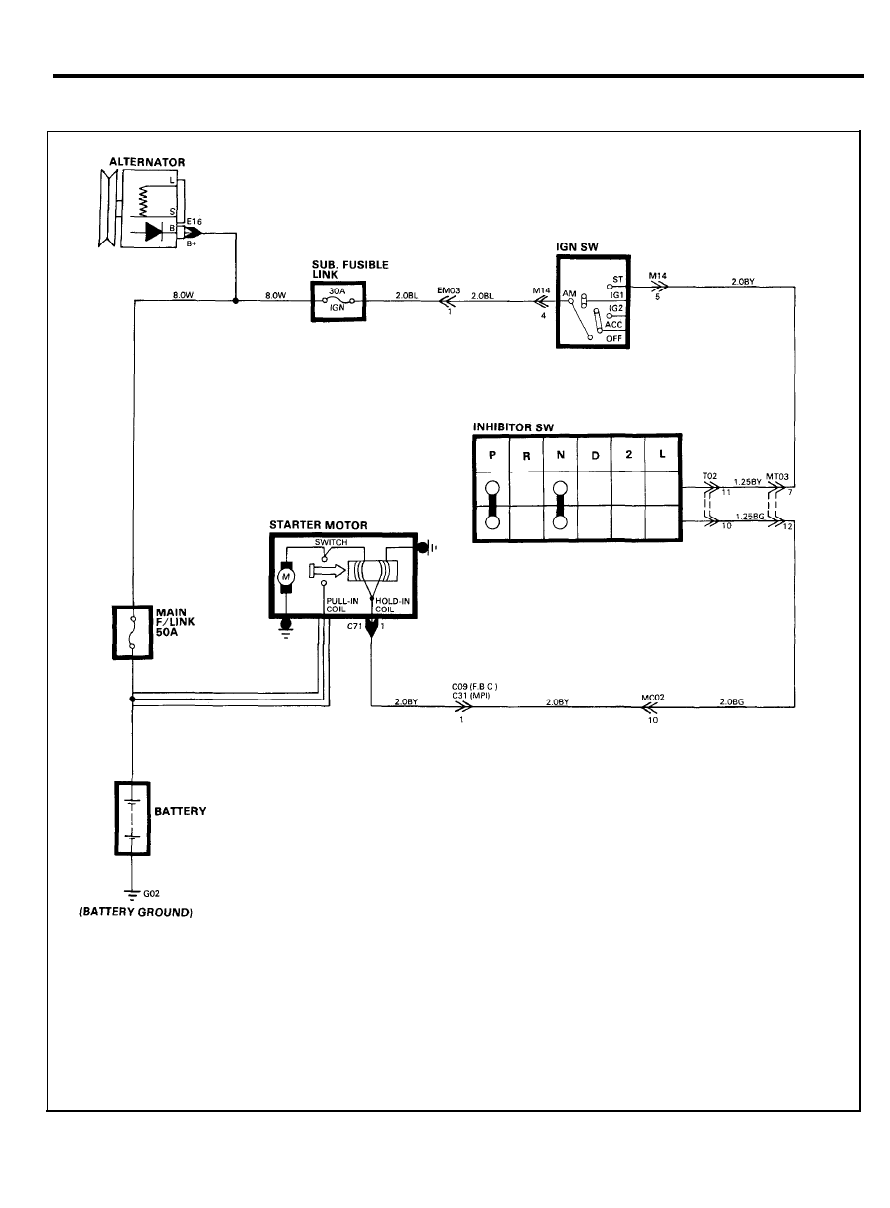
STARTING SYSTEM (A/T)
CIRCUIT DIAGRAM
18
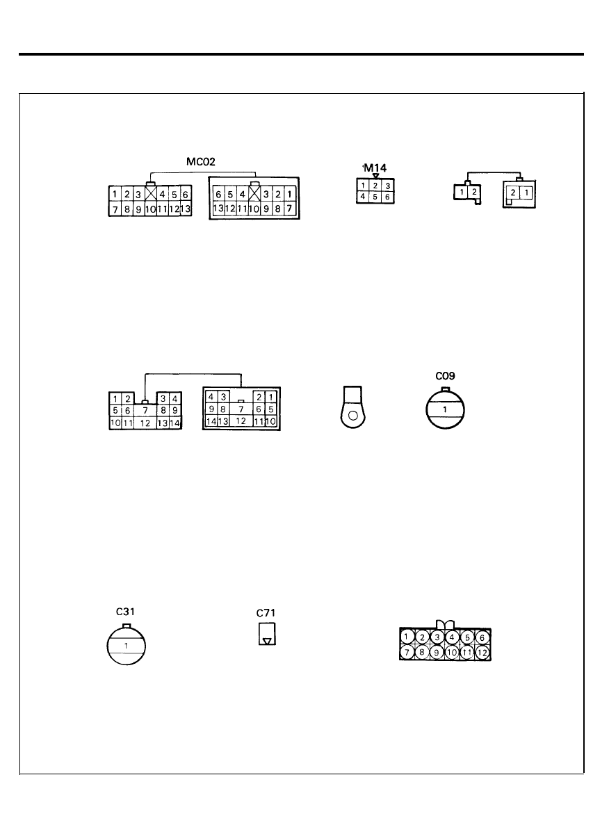
STARTING SYSTEM (A/T)
CONFIGURATION OF CONNECTORS
MT03
E16
EM03
T02
19
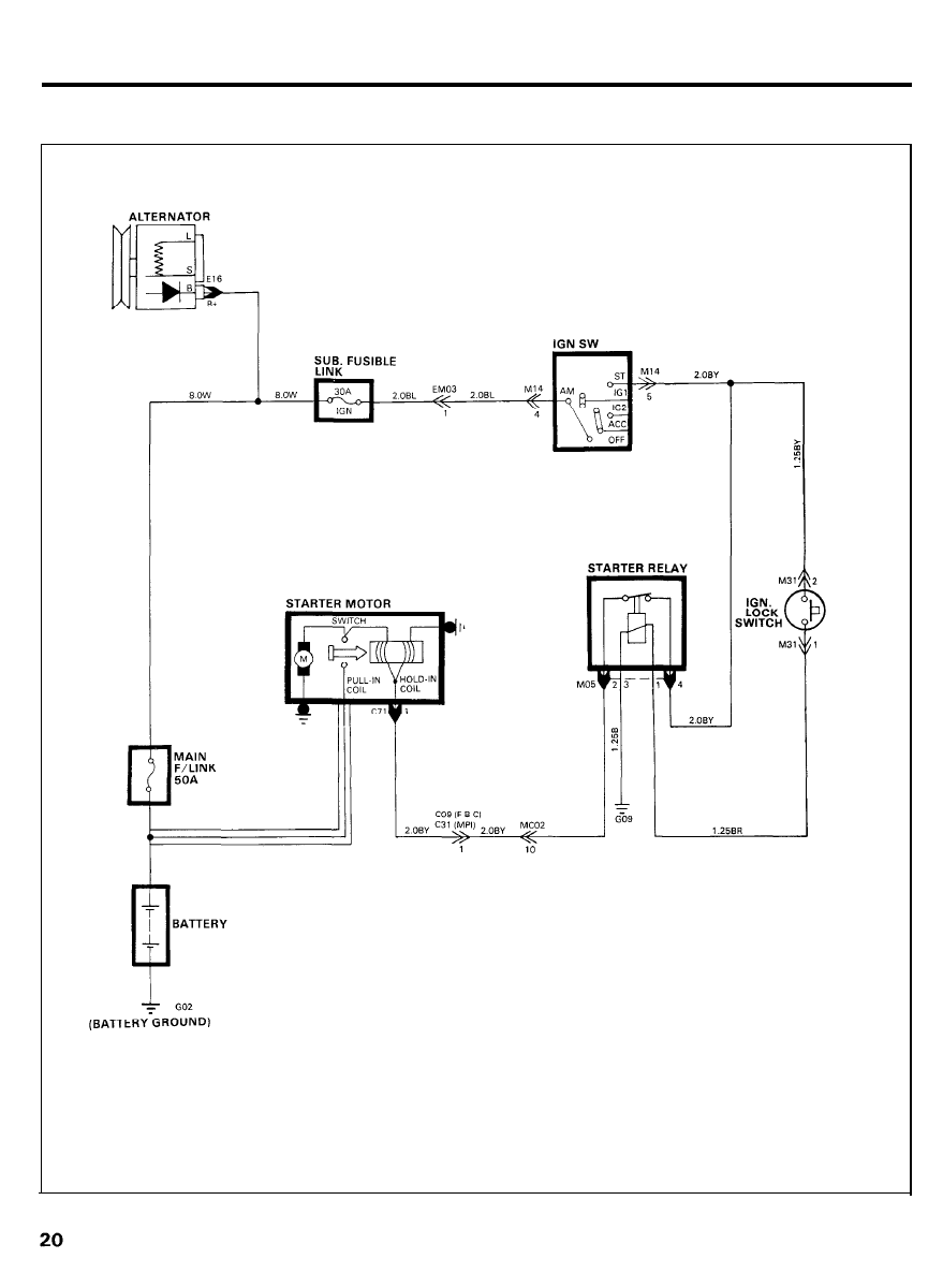
STARTING SYSTEM (M/T)
CIRCUIT DIAGRAM
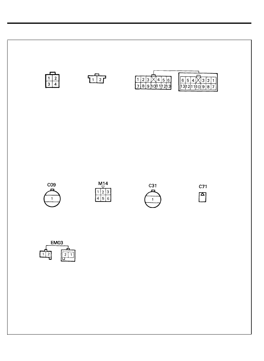
STARTING SYSTEM (M/T)
CONFIGURATION OF CONNECTORS
MO5
M31
MC02
21
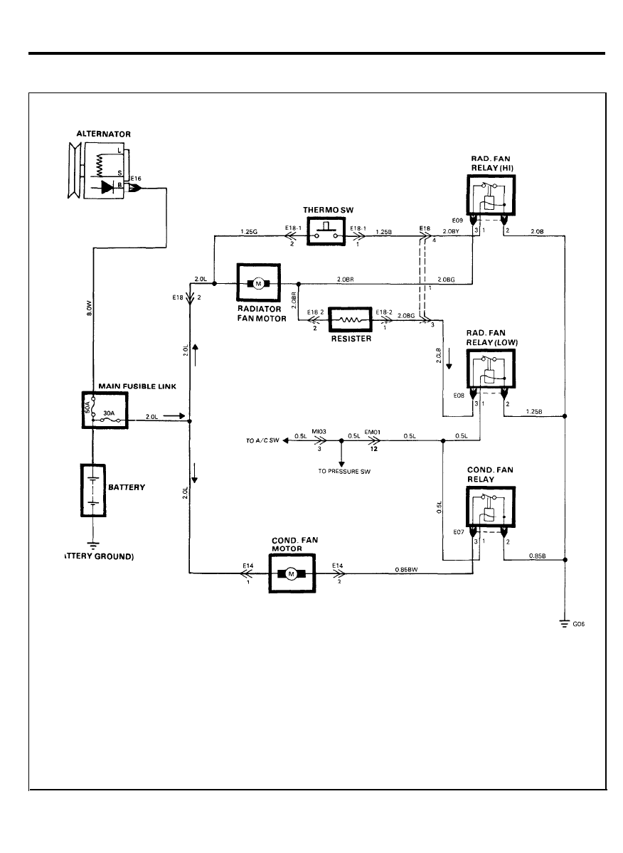
COOLING SYSTEM
CIRCUIT DIAGRAM
22
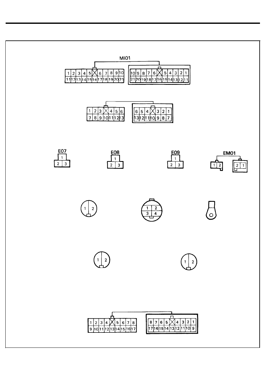
COOLING SYSTEM
CONFIGURATION OF CONNECTORS
Ml03
E14
E18
E18-1
E18-2
EM01
E16
23
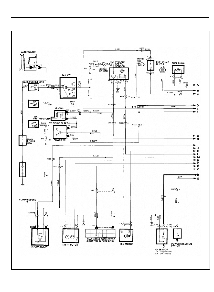
MPI SYSTEM
CIRCUIT DIAGRAM
24
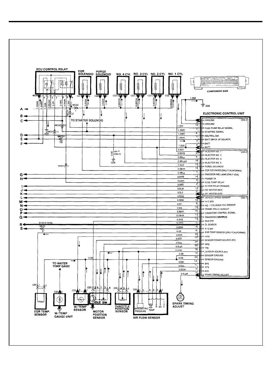
MPI SYSTEM
CIRCUIT DIAGRAM
25
CONFIGURATION OF CONNECTORS
E33
MC01
MC02
MT03
EM01
EM02
Ml02
EM03
E13
26
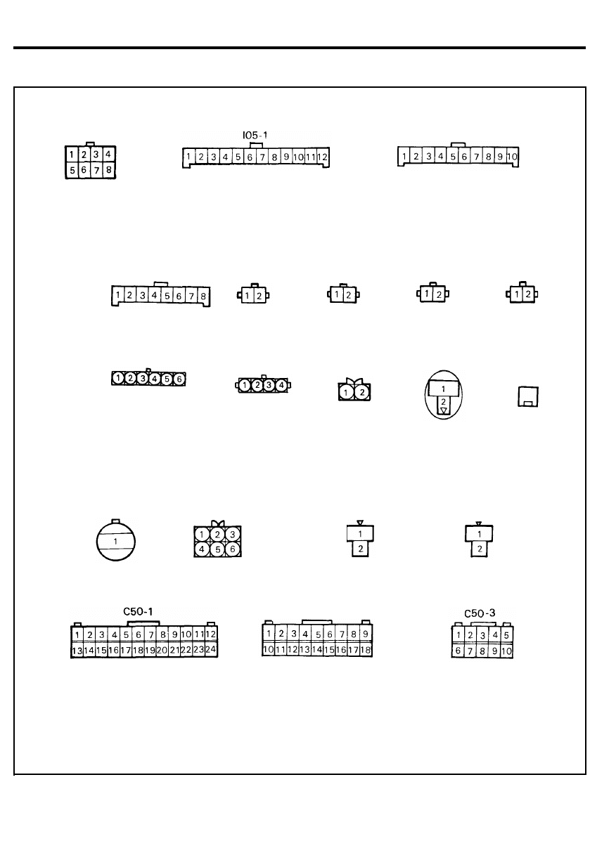
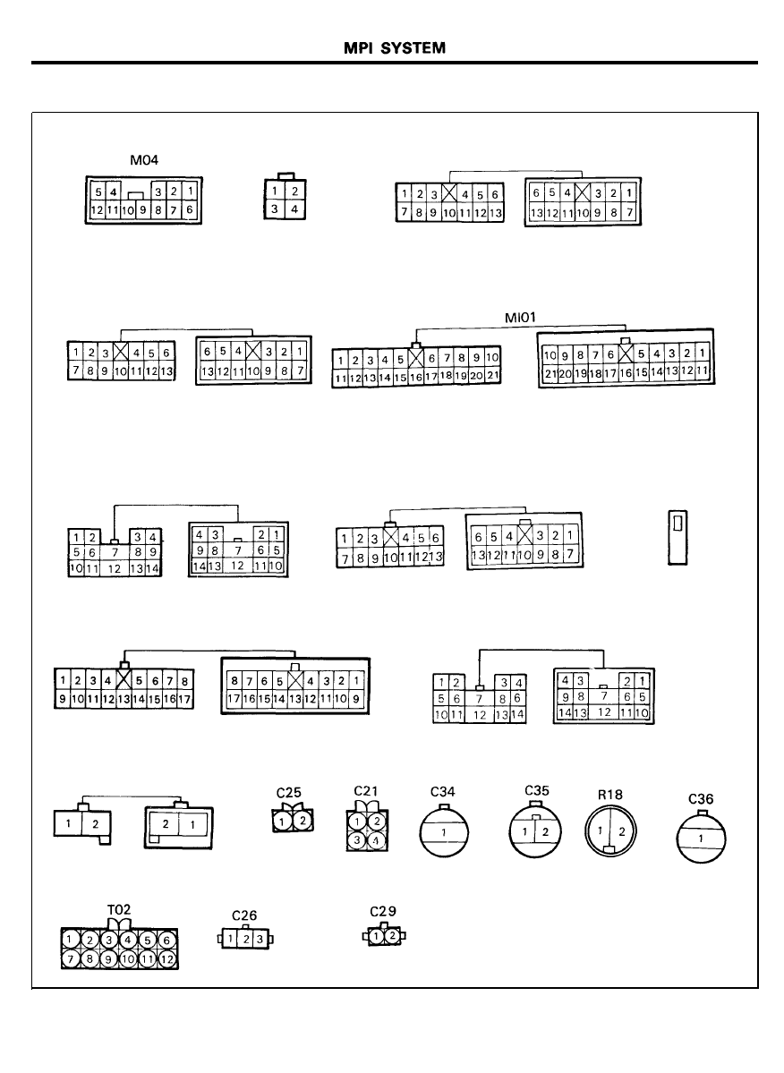
MPI SYSTEM
CONFIGURATION OF CONNECTORS
M29
I05-3
C22-1
C27
C37
C28
C38
C22-2
C50-2
C30
C39
I05-2
C22-3
C22-4
C32
C41
C33
27
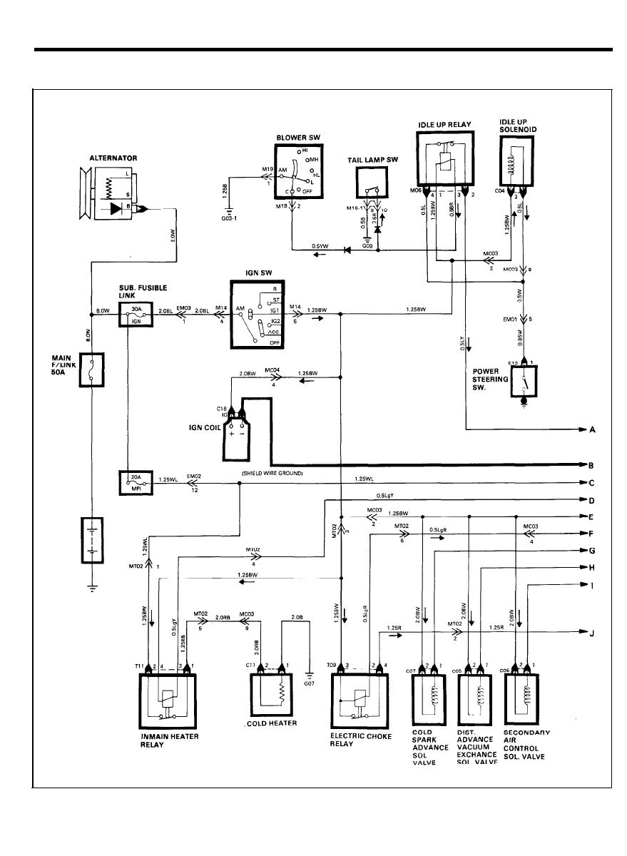
FBC SYSTEM
CIRCUIT DIAGRAM
28
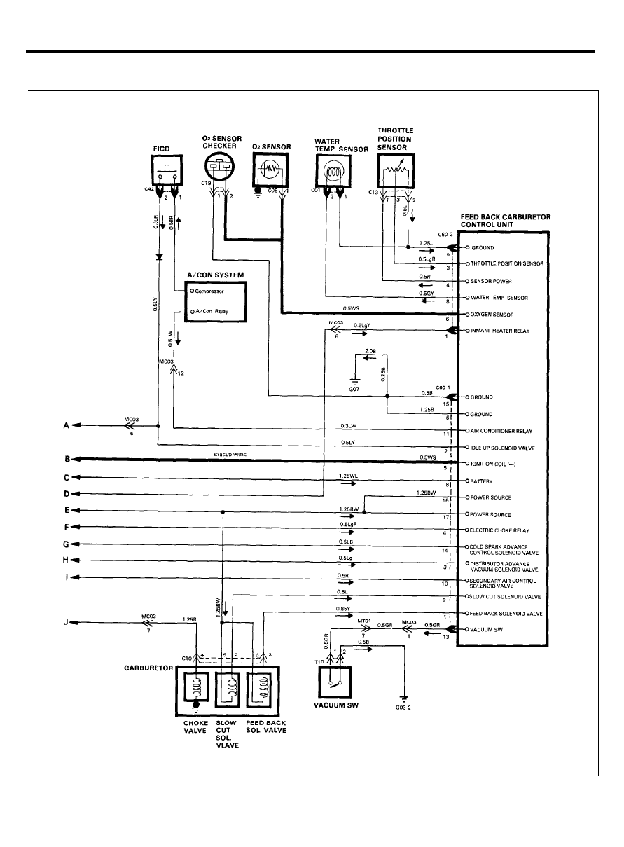
FBC SYSTEM
CIRCUIT DIAGRAM
29
FBC SYSTEM
CONFIGURATION OF CONNECTORS
M06
MT02
MC03
MT03
T11
EM02
3 0
FBC SYSTEM
CONFIGURATION OF CONNECTORS
C60-1
C60-2
C01
T10
C08
C42
M09
31
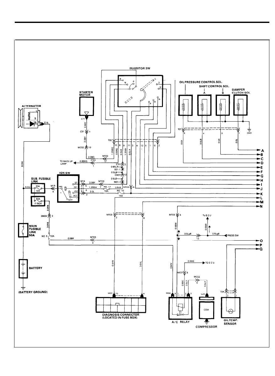
ELECTRONIC LOCK UP CONTROL (4-SPEED)
CIRCUIT DIAGRAM
3 2
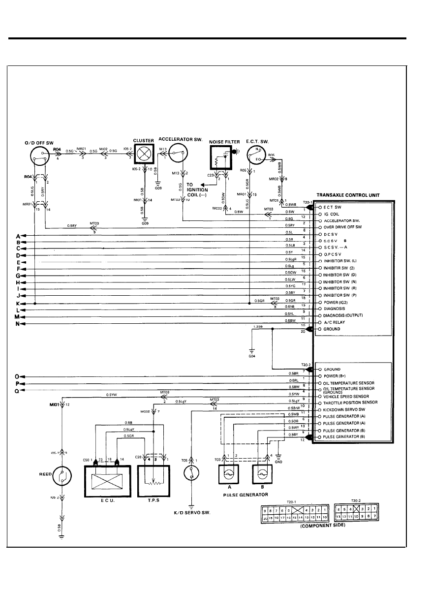
ELECTRONIC LOCK UP CONTROL (4-SPEED)
CIRCUIT DIAGRAM
3 3
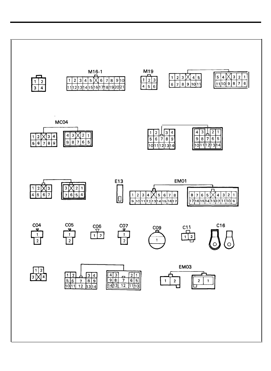
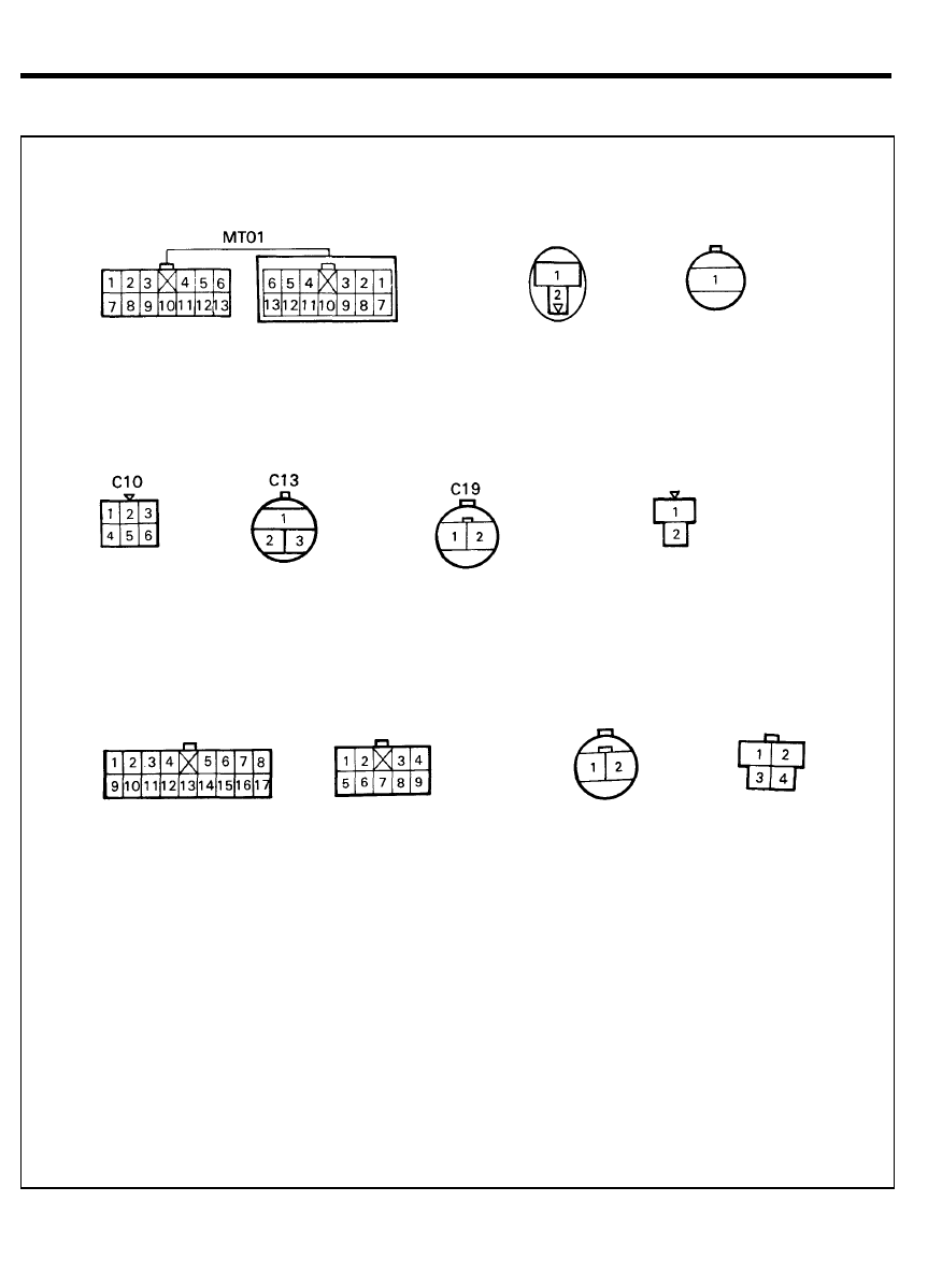
ELECTRONIC LOCK UP CONTROL (4-SPEED)
CONFIGURATION OF CONNECTORS
M04
T01
T02
3 4
ELECTRONIC LOCK UP CONTROL (4-SPEED)
CONFIGURATION OF CONNECTORS
M13
M14
MC01
C23
ET01
R05
T03
R04
T04
T05
T20-2
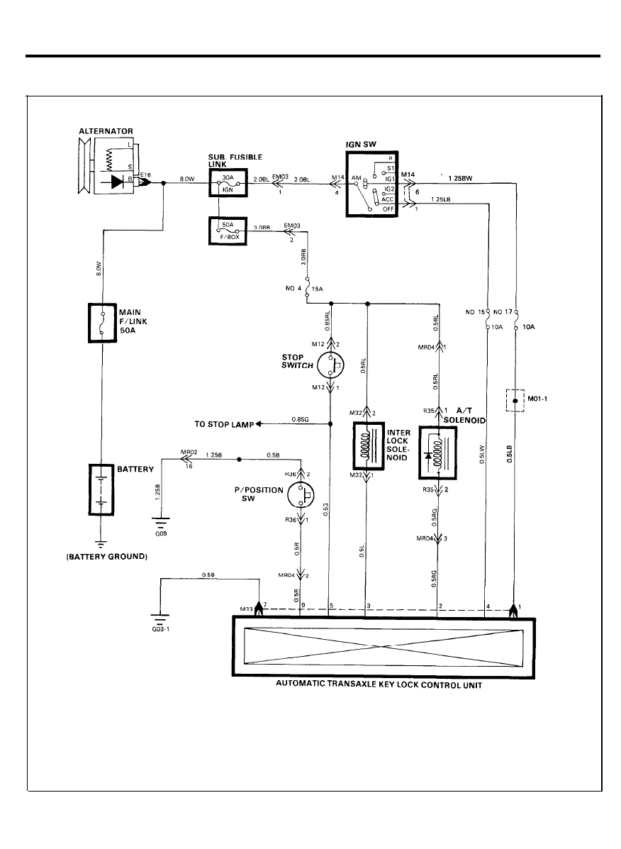
AUTOMATIC TRANSAXLE KEY LOCK CONTROL
CIRCUIT DIAGRAM
3 6
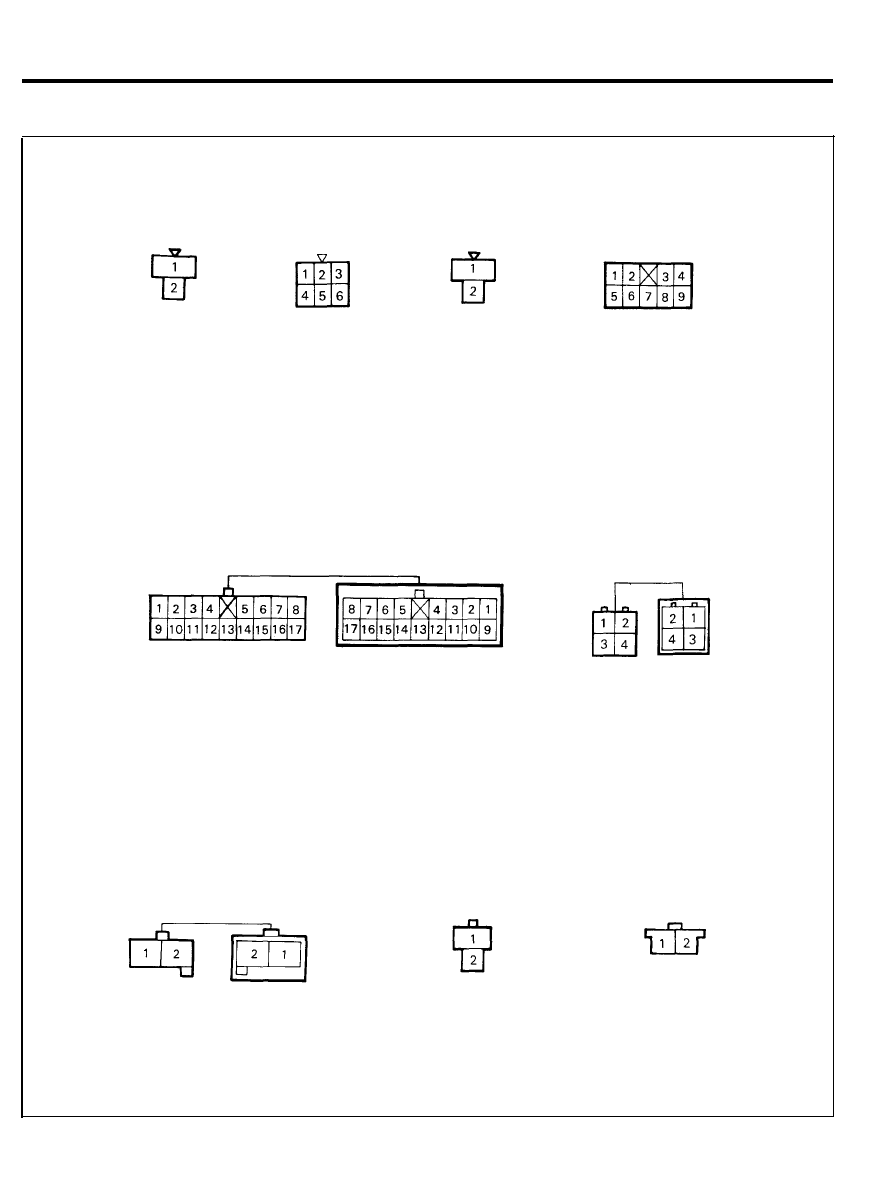
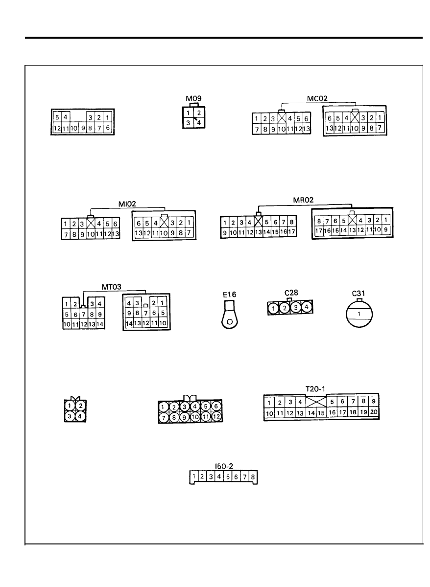
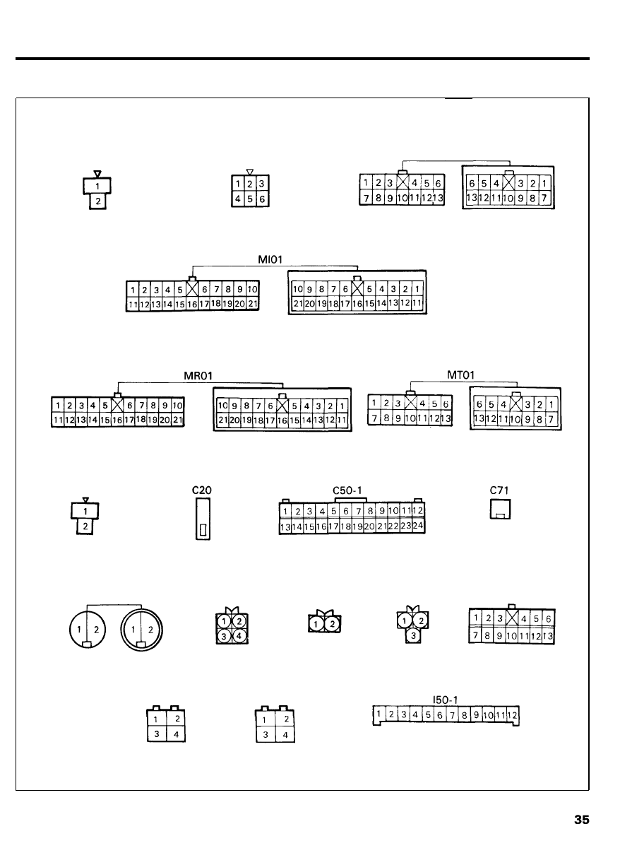
AUTOMATIC TRANSAXLE KEY LOCK CONTROL
CONFIGURATION OF CONNECTORS
M12
M14
MR02
EM03
M32
R35
R36
M33
MR04
3 7
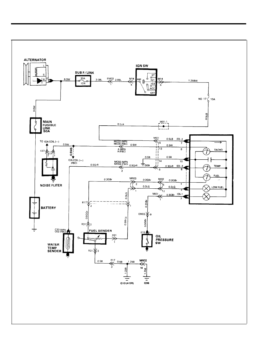
G A U G E S
CIRCUIT DIAGRAM
3 8
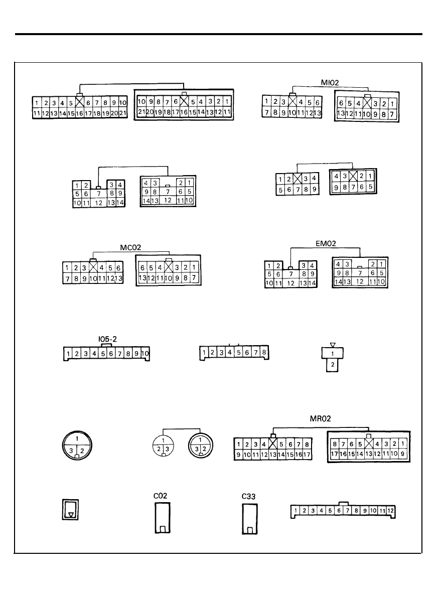
GAUGES
CONFIGURATION OF CONNECTORS
Ml01
MR03
R31
E15
R 1 7
MC04
I05-3
C23
I05-1
3 9
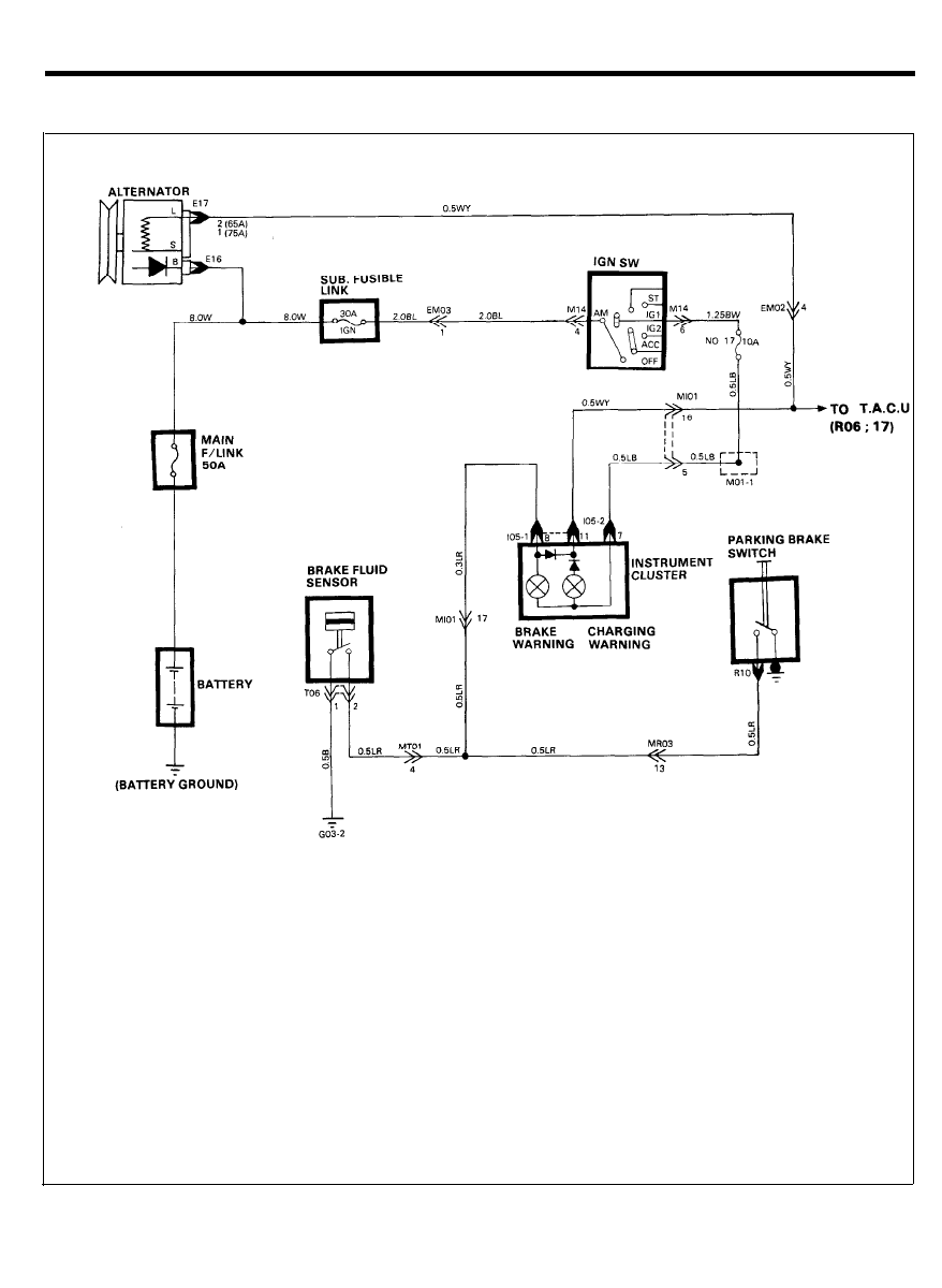
BRAKE WARNING
CIRCUIT DIAGRAM
4 0
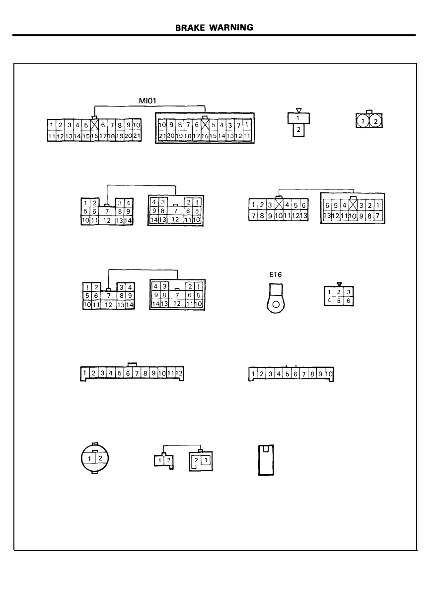
CONFIGURATION OF CONNECTORS
MR03
EM02
I05-1
T06
EM03
E17
(65A)
E17
(75A)
MT01
M14
I05-2
R10
41
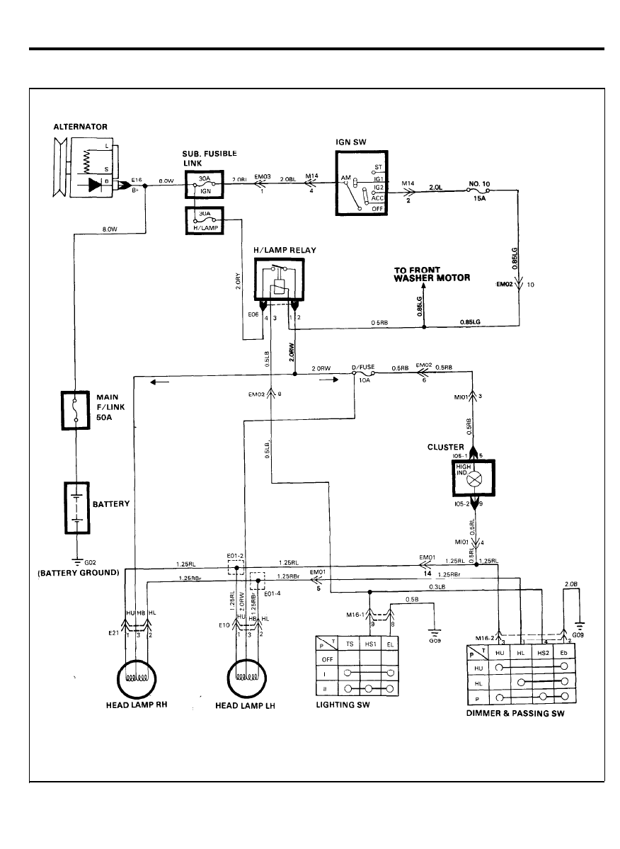
HEAD LAMP (U.S.A.)
CIRCUIT DIAGRAM
4 2
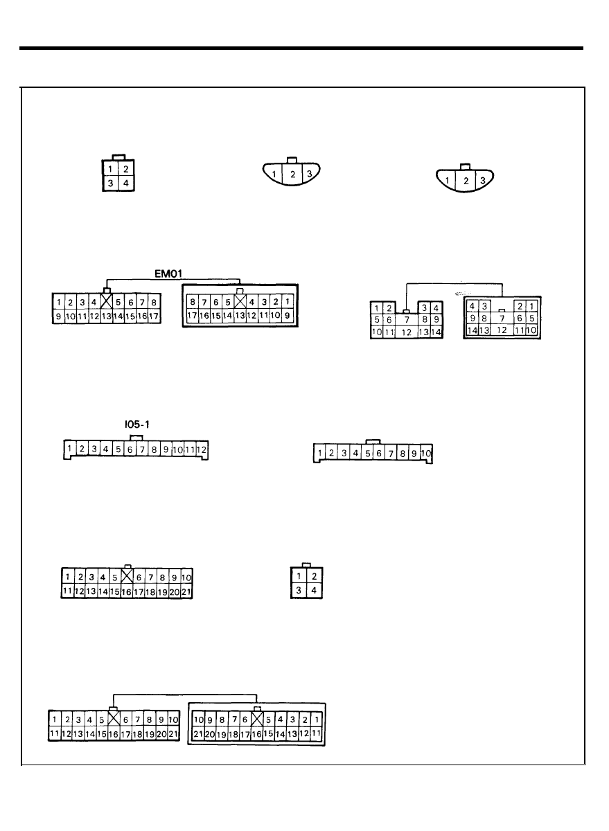
HEAD LAMP (U.S.A.)
CONFIGURATION OF CONNECTORS
E06
E10
M16-1
M16-2
EM02
I05-2
Ml01
E21
4 3
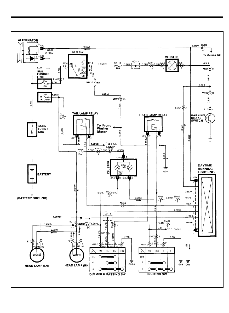
DAYTIME RUNNING LIGHT (CANADA)
CIRCUIT DIAGRAM
4 4
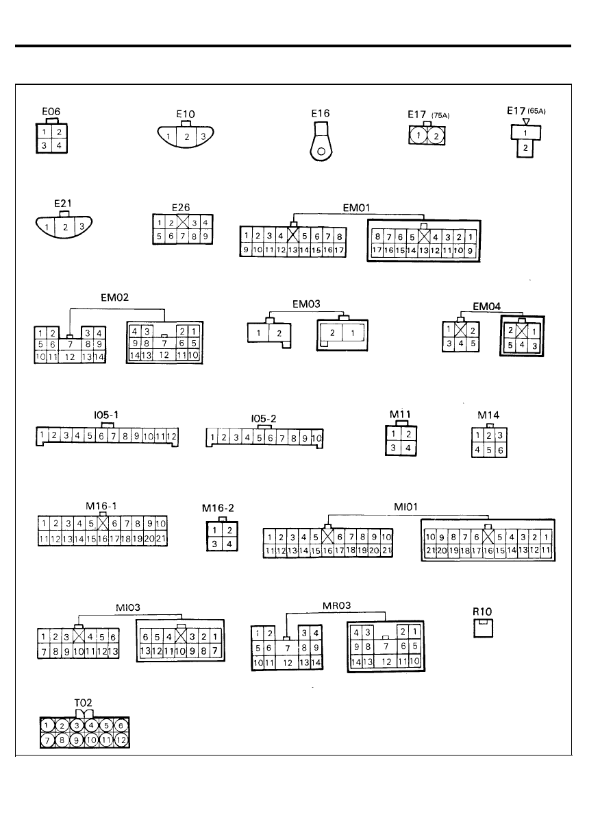
DAYTIME RUNNING LIGHT (CANADA)
CONFIGURATION OF CONNECTORS
4 5
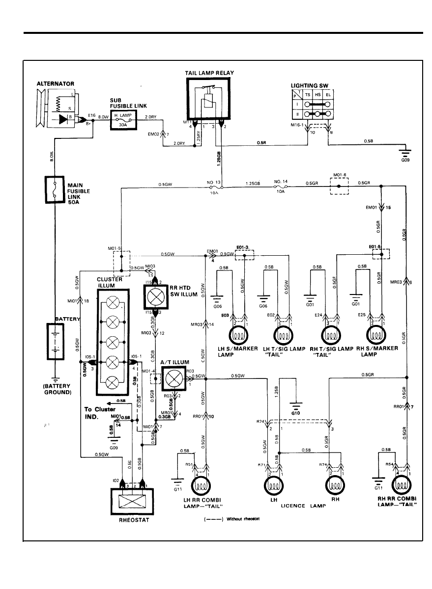
TAIL LAMP (4 DOOR)
CIRCUIT DIAGRAM
4 6
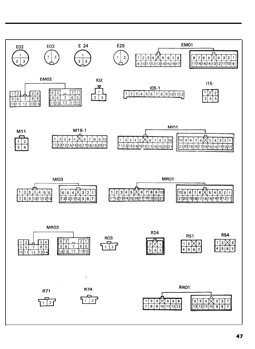
TAIL LAMP (4 DOOR)
CONFIGURATION OF CONNECTORS
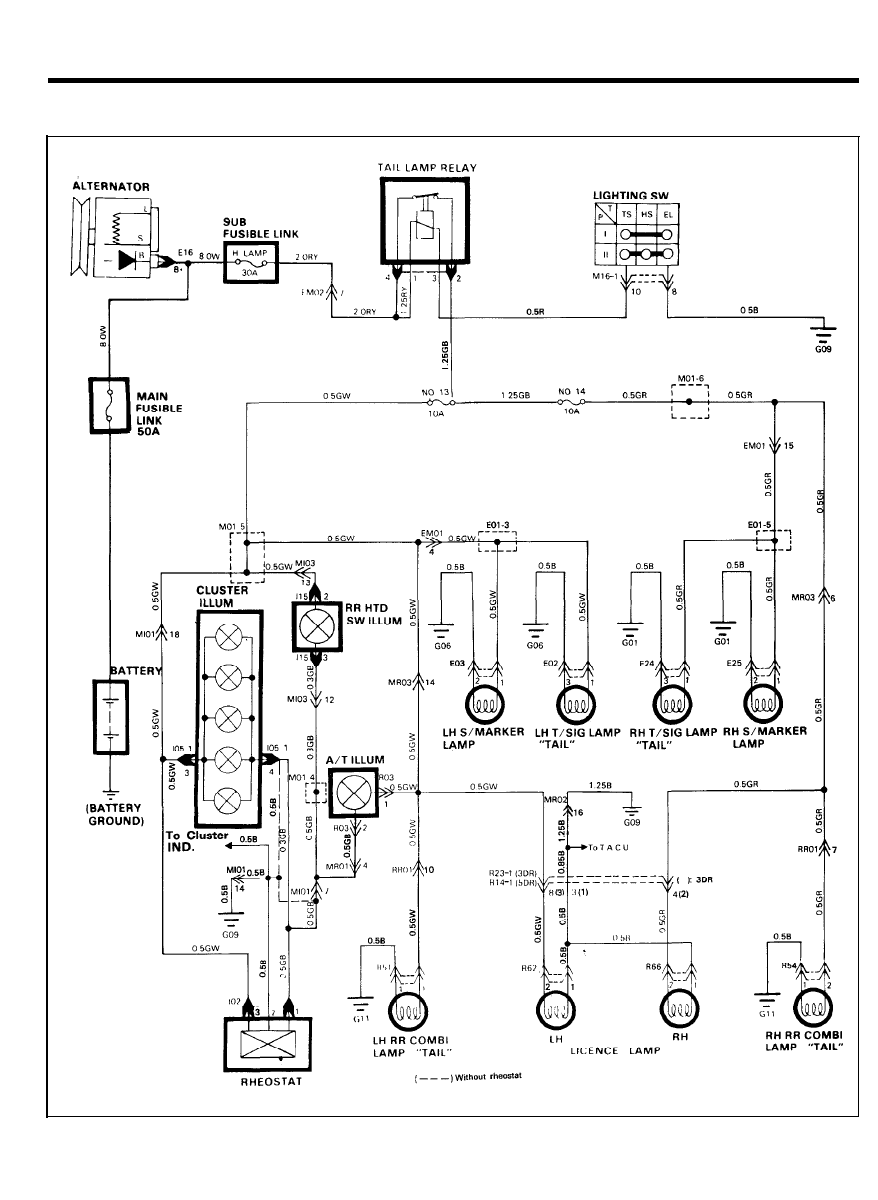
TAIL LAMP (3,5 DOOR)
CIRCUIT DIAGRAM
4 8
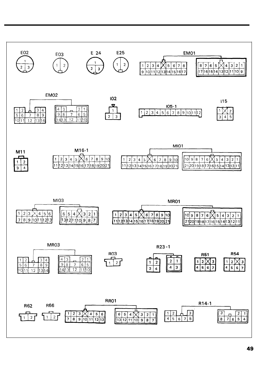
TAIL LAMP (3 DOOR)
CONFIGURATION OF CONNECTORS
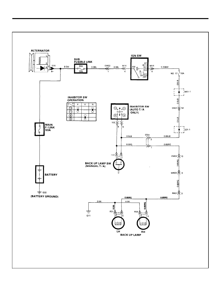
BACK UP LAMP
CIRCUIT DIAGRAM
5 0
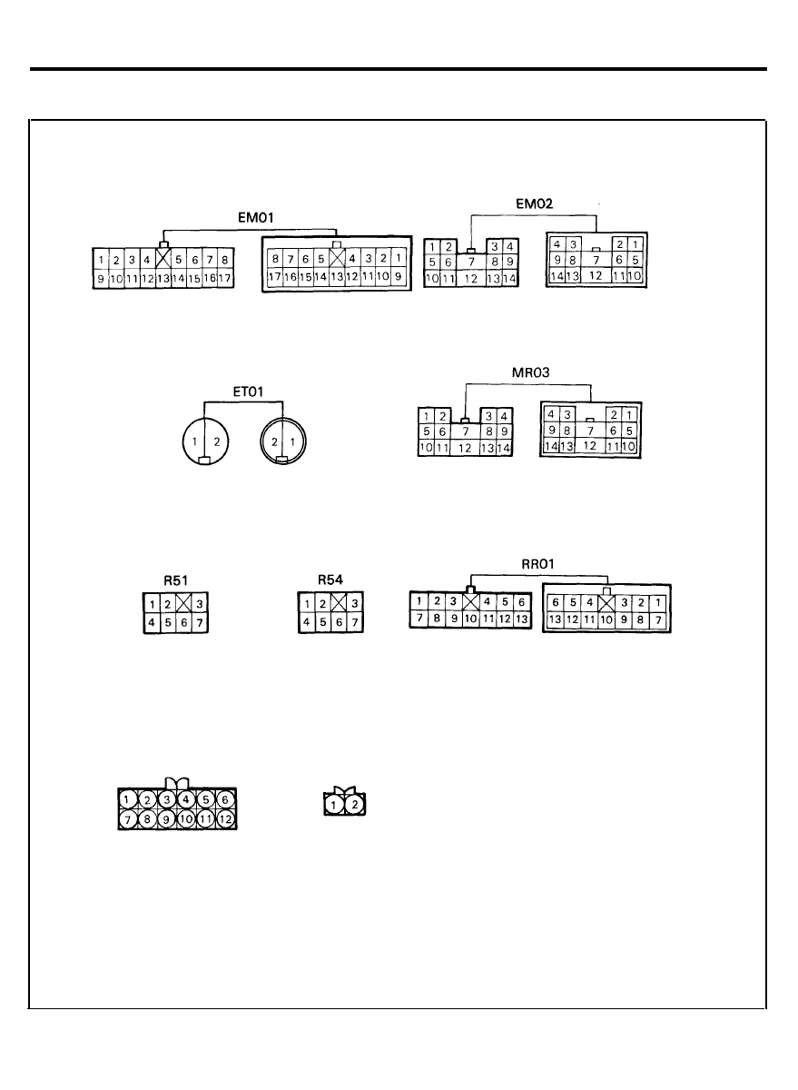
BACK UP LAMP
CONFIGURATION OF CONNECTORS
T02
T13
51
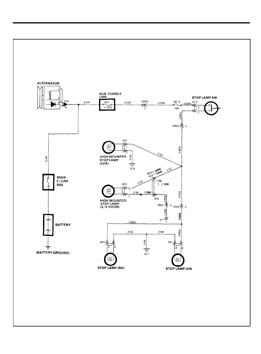
STOP LAMP
CIRCUIT DIAGRAM
5 2
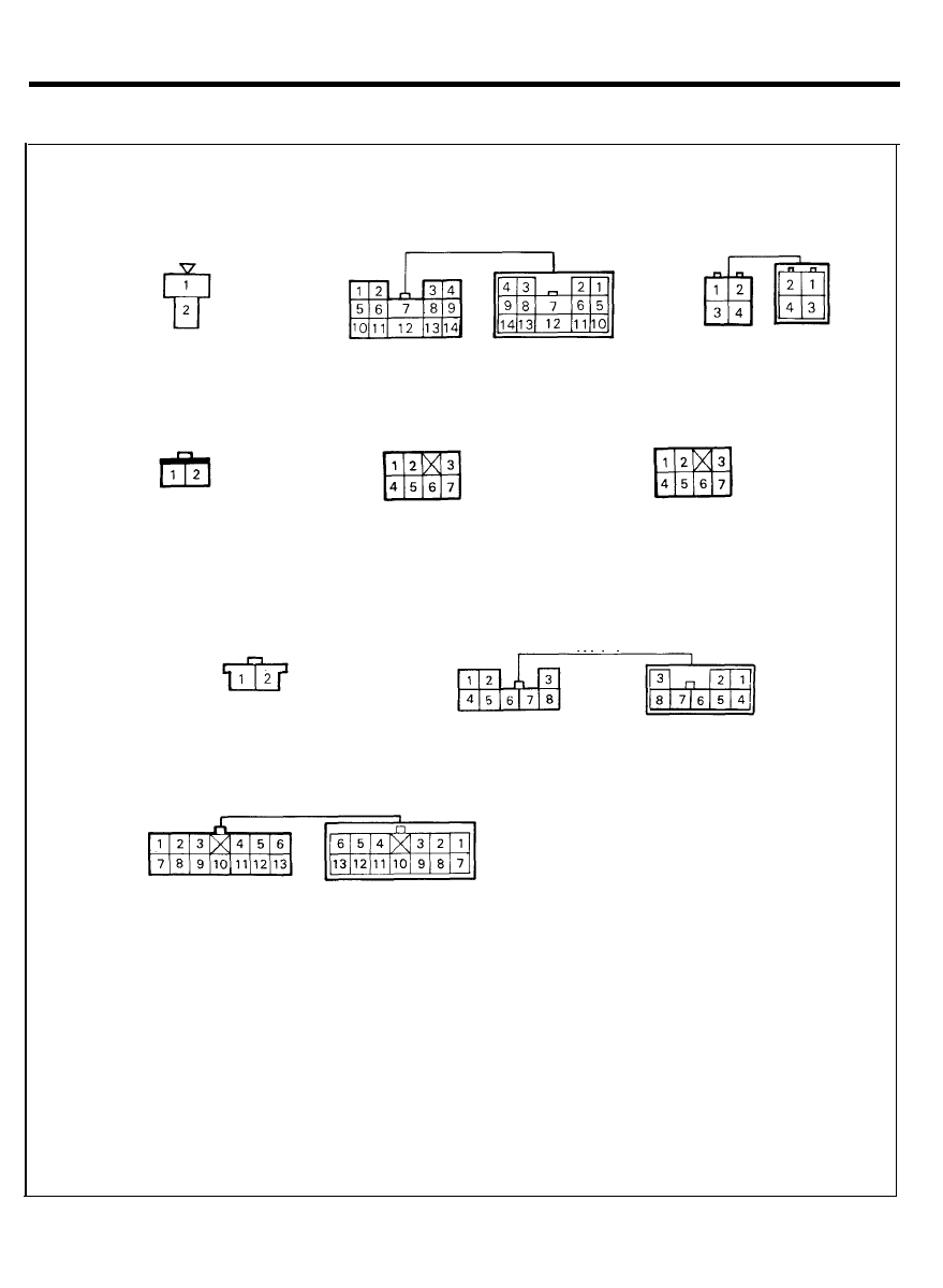
STOP LAMP
CONFIGURATION OF CONNECTORS
M12
R27
R51
R54
R63
R14-1
RR01
MR03
R23-1
5 3
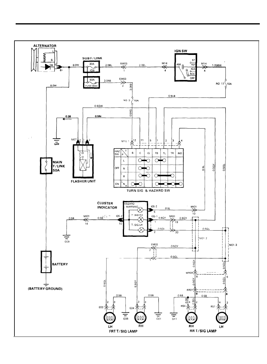
TURN SIGNALS AND HAZARD WARNING LAMP
CIRCUIT DIAGRAM
5 4
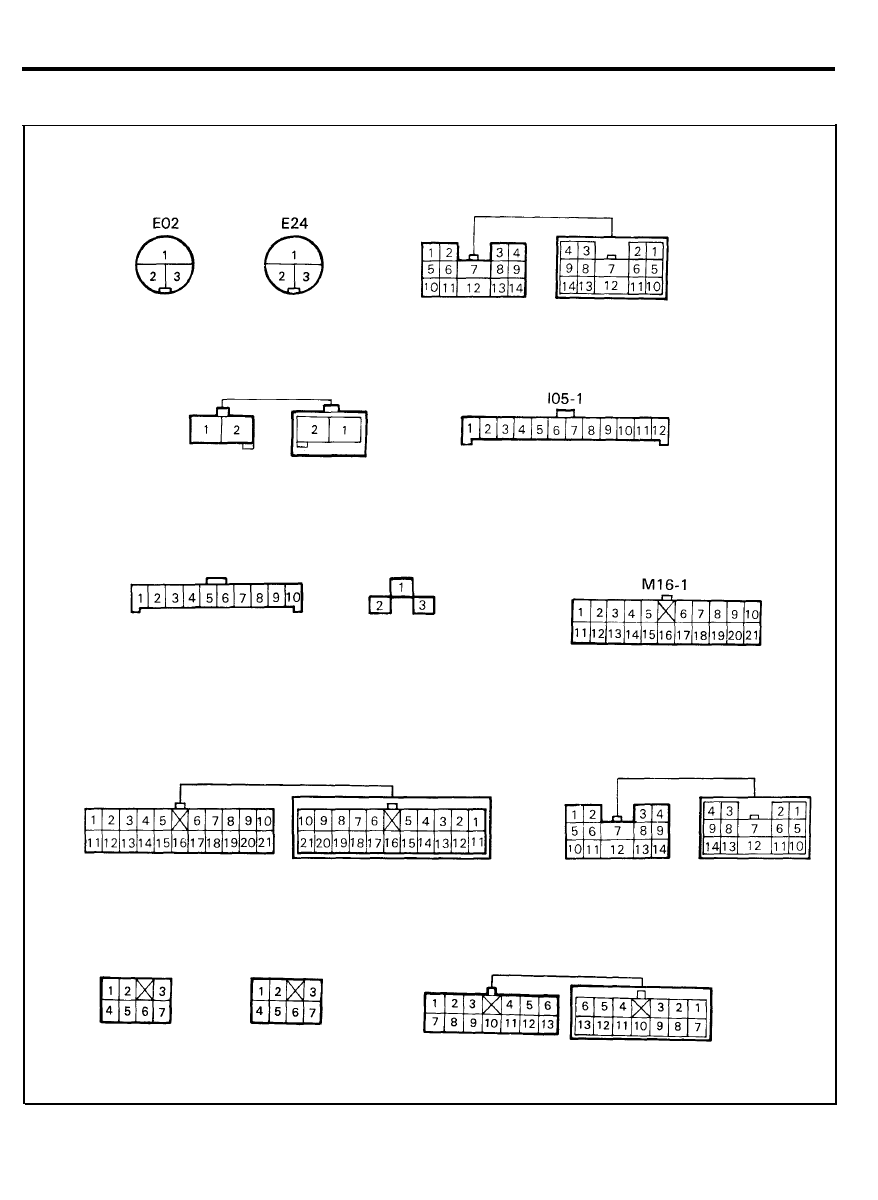
TURN SIGNALS AND HAZARD WARNING LAMP
CONFIGURATION OF CONNECTORS
EM03
I05-2
MO7
EM02
Ml01
MR03
R51
R54
RR01
5 5
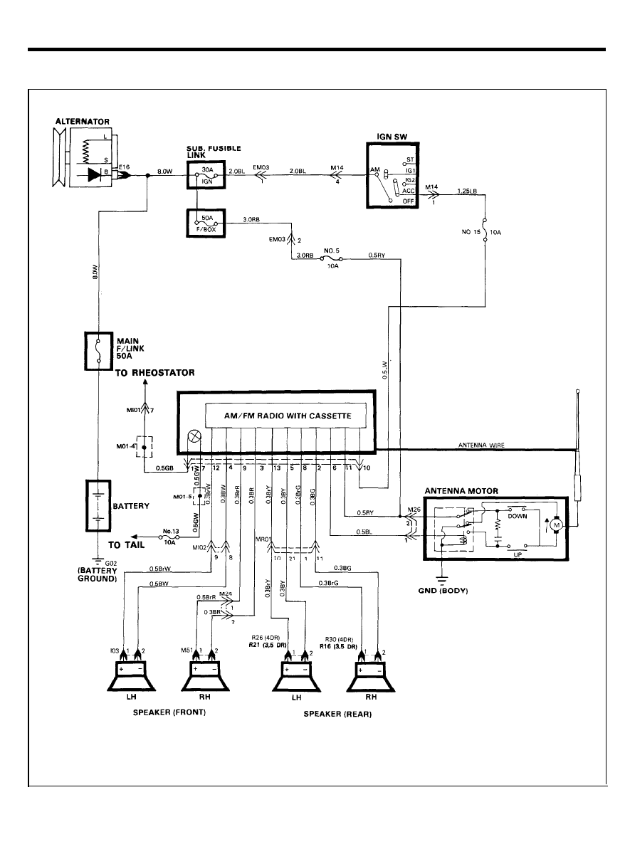
AUDIO
CIRCUIT DIAGRAM
5 6
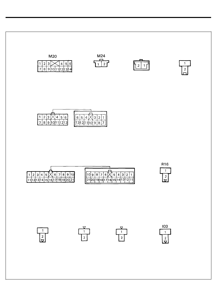
AUDIO
CONFIGURATION OF CONNECTORS
Ml02
MR01
M26
R21
R 2 6
R30
M51
5 7
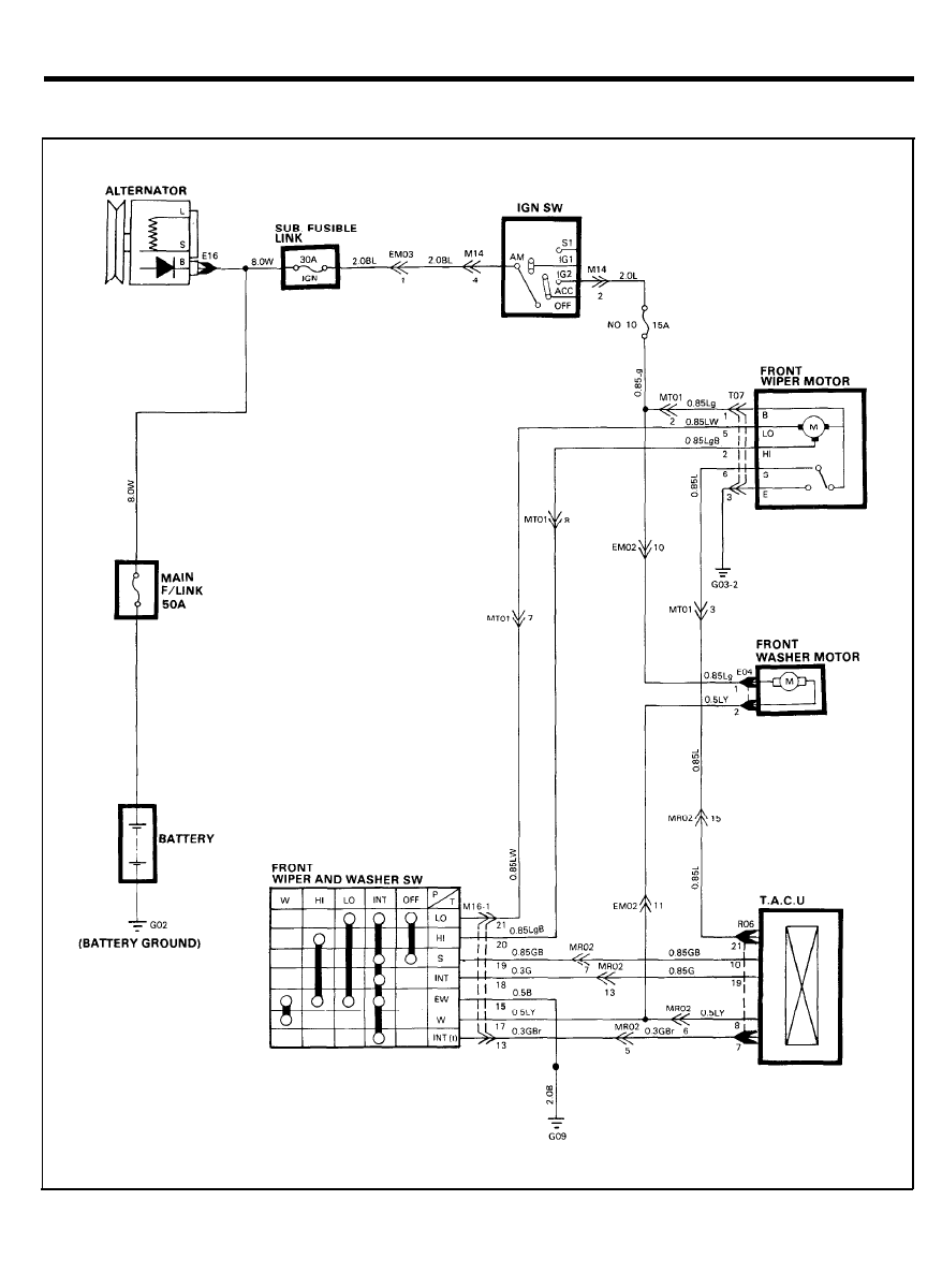
FRONT WIPER AND WASHER
CIRCUIT DIAGRAM
5 8
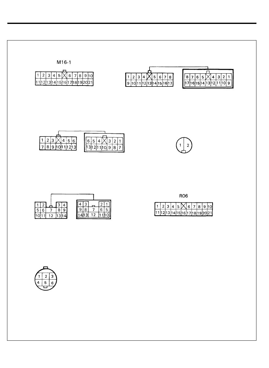
FRONT WIPER AND WASHER
CONFIGURATION OF CONNECTORS
MT01
E04
EM02
T07
MR02
5 9
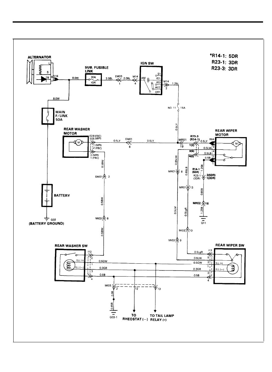
REAR WIPER AND WASHER
CIRCUIT DIAGRAM
6 0
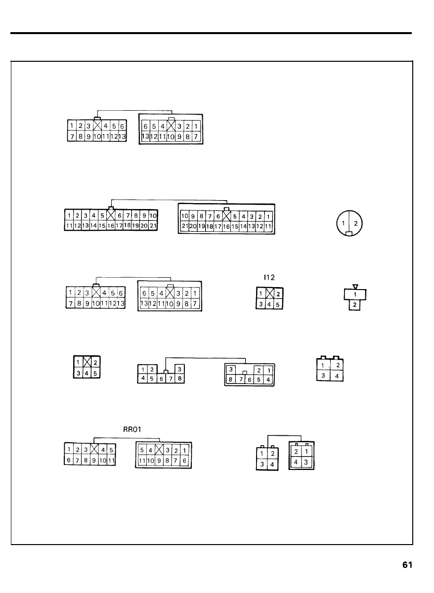
REAR WIPER AND WASHER
CONFIGURATION OF CONNECTORS
Ml03
EM01
MR01
I13
R14-1
R23-1
E05
R64
E28
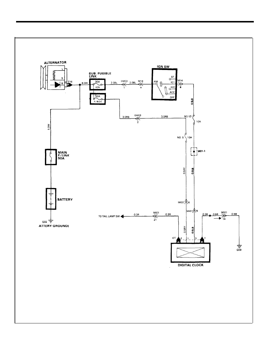
CLOCK
CIRCUIT DIAGRAM
6 2
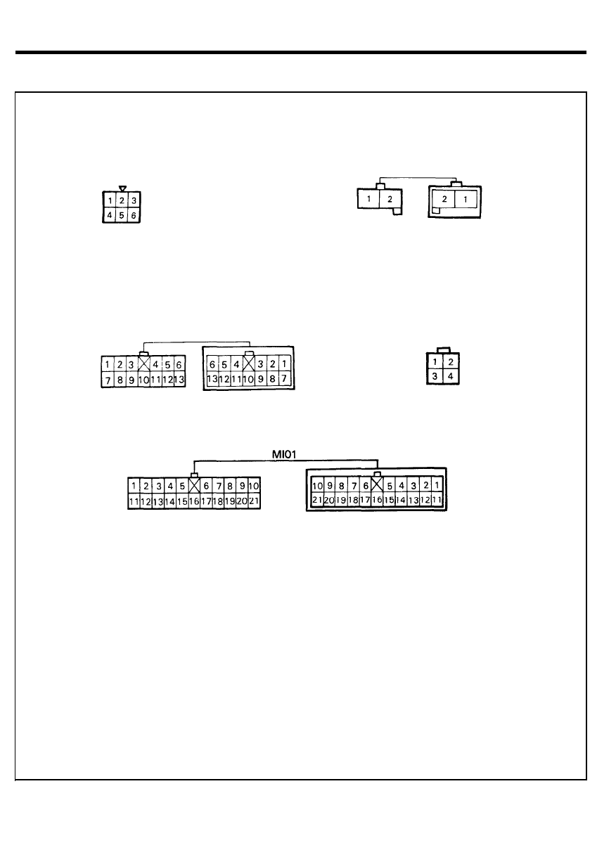
CLOCK
CONFIGURATION OF CONNECTORS
M14
Ml03
EM03
I01
6 3
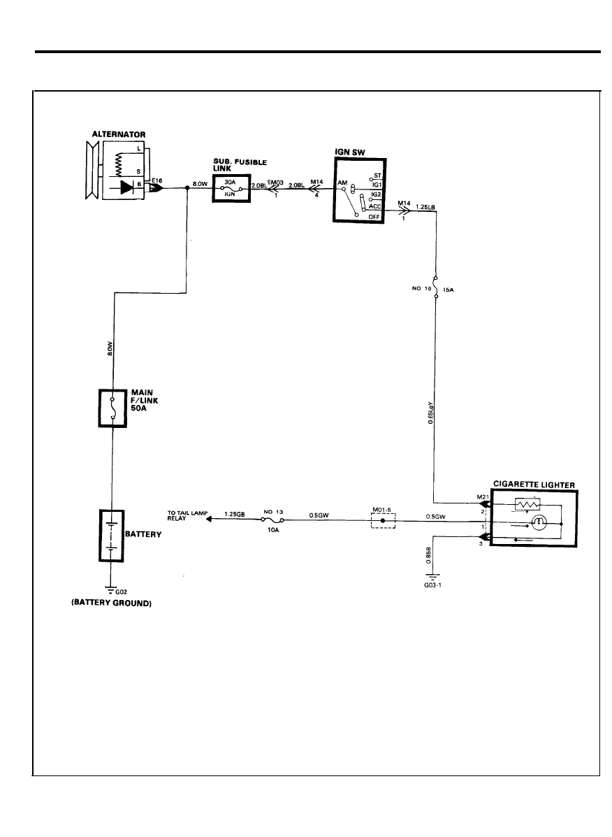
CIGARETTE LIGHTER
CIRCUIT DIAGRAM
6 4
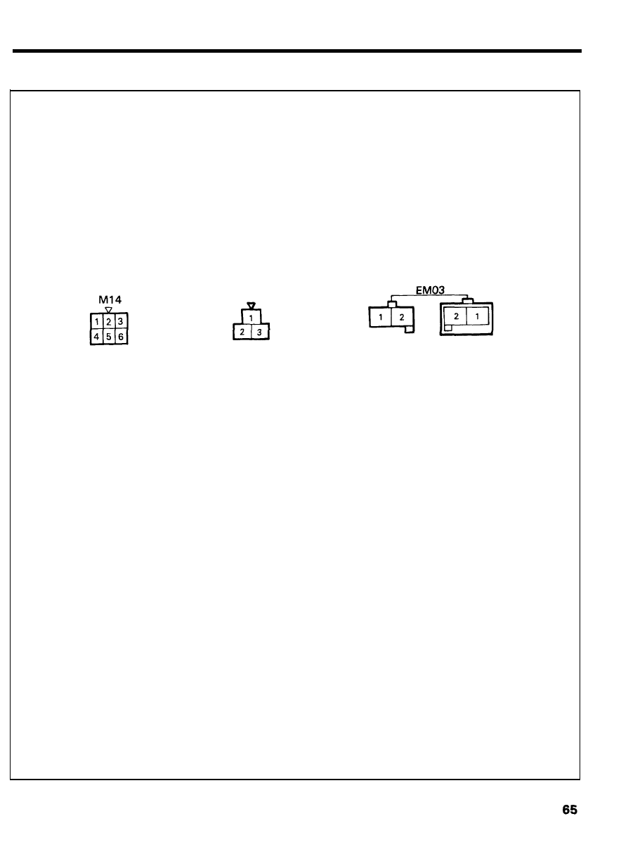
CIGARETTE LIGHTER
CONFIGURATION OF CONNECTORS
M21
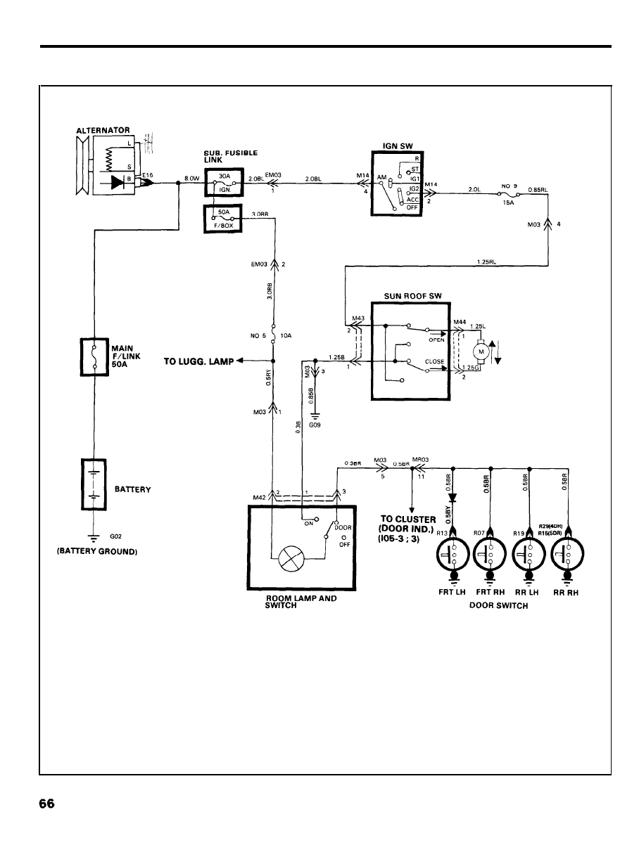
SUN ROOF
CIRCUIT DIAGRAM
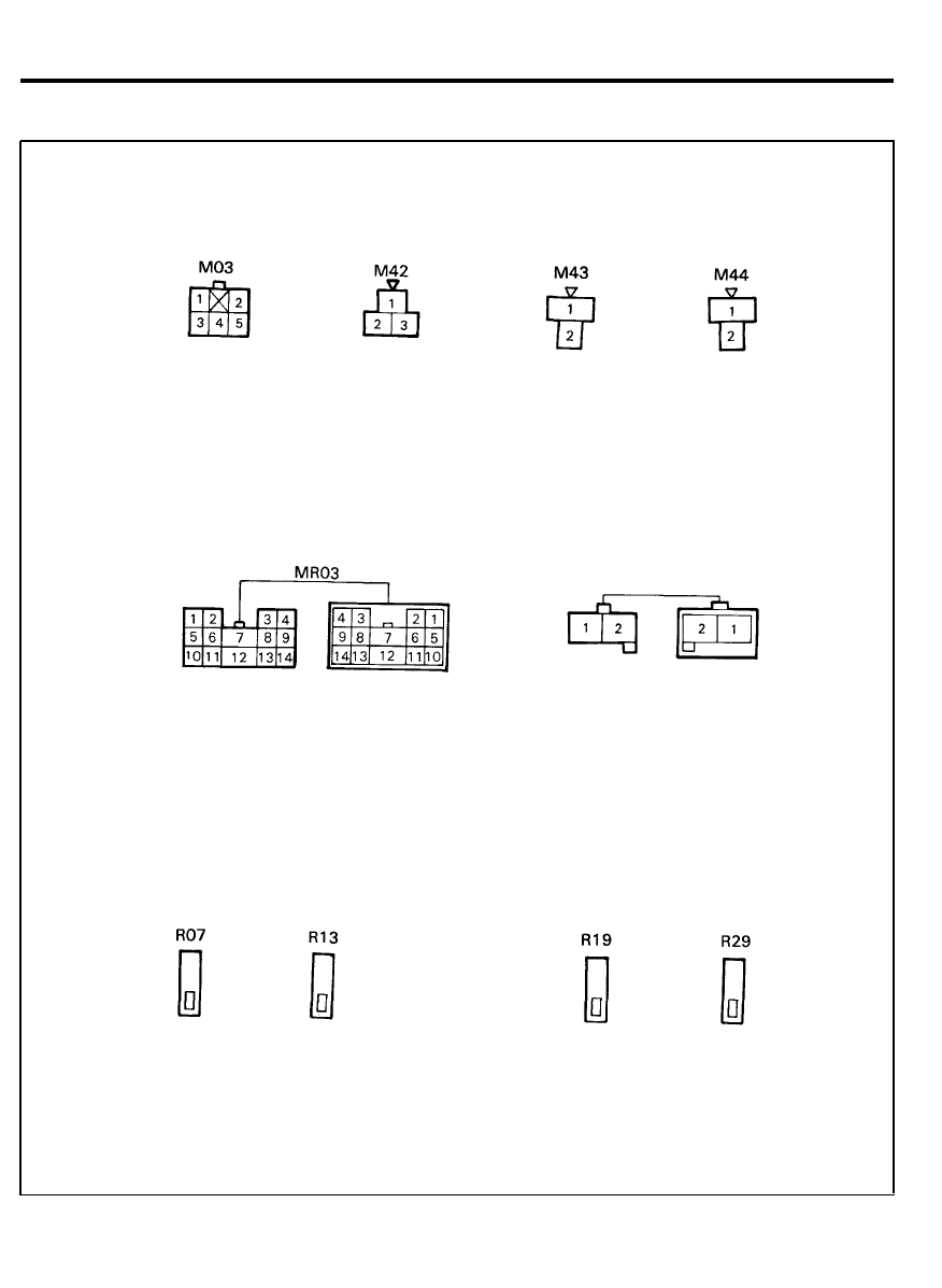
SUN ROOF
CONFIGURATION OF CONNECTORS
6 7
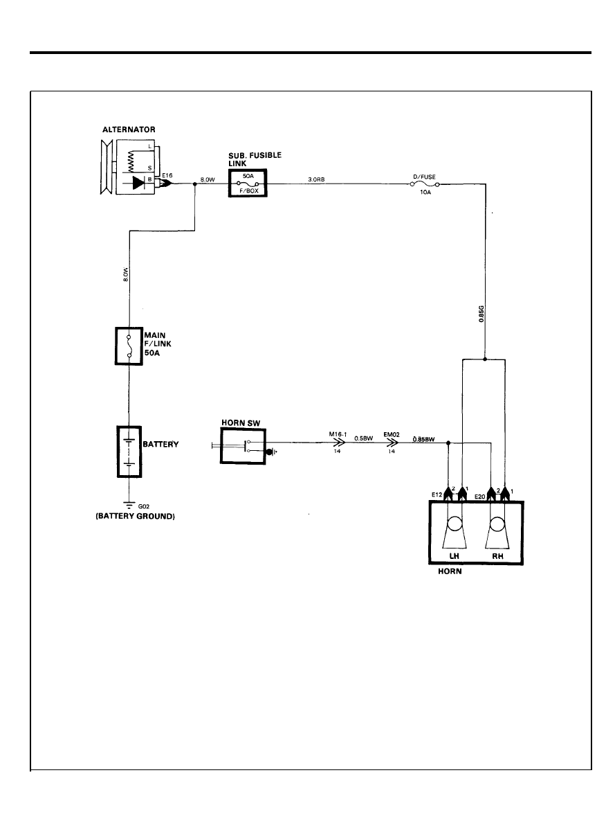
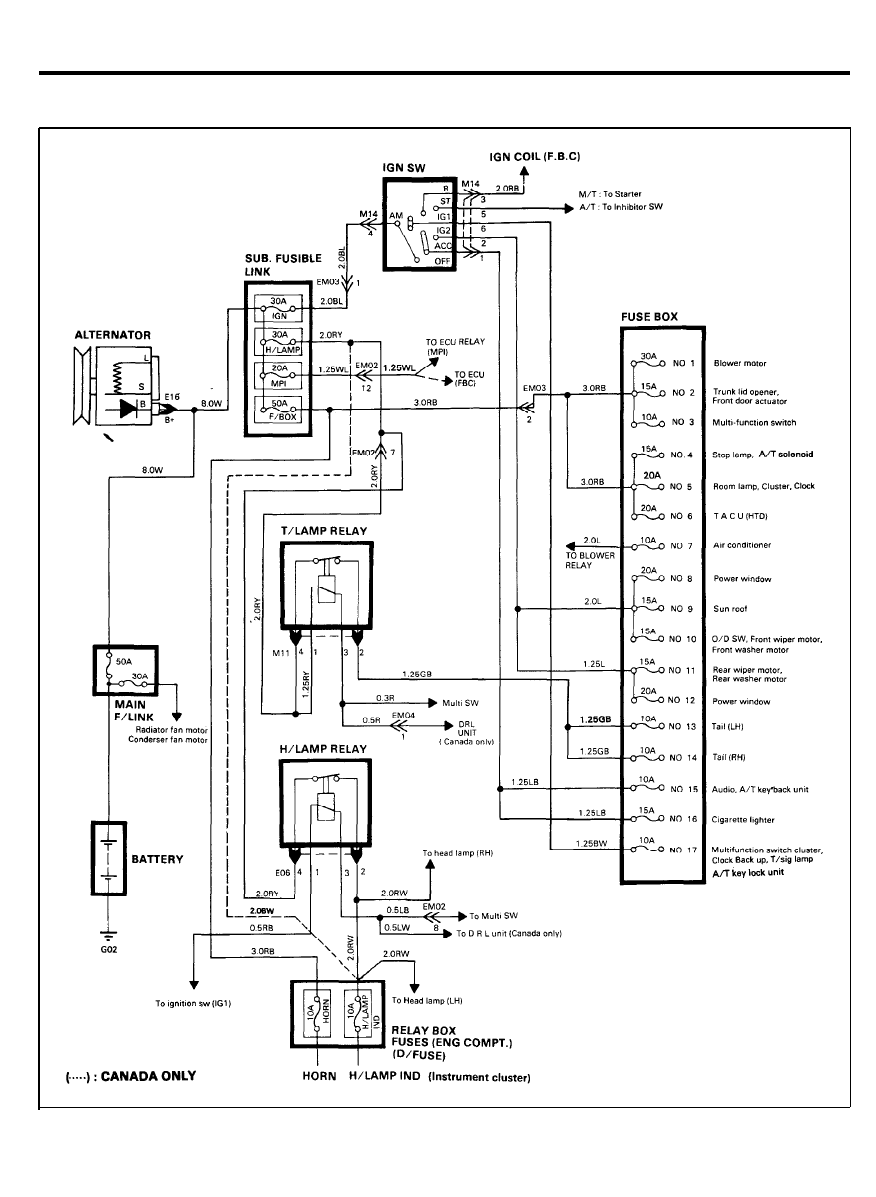
HORN
CIRCUIT DIAGRAM
6 8
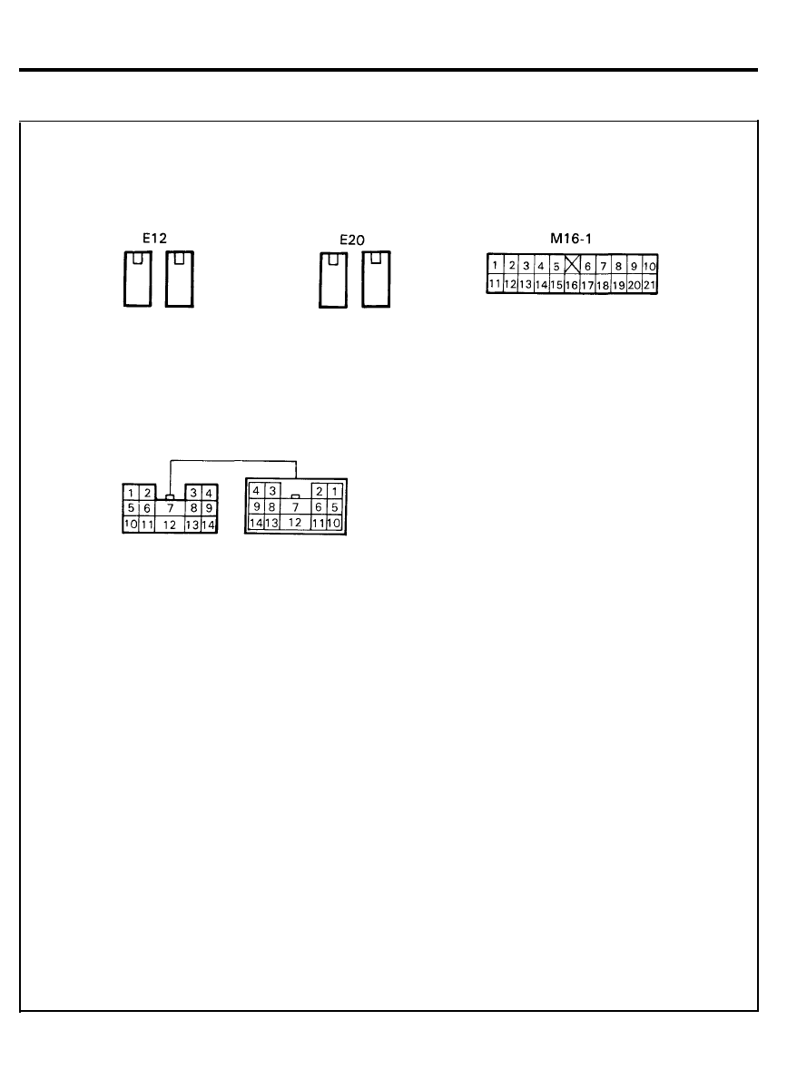
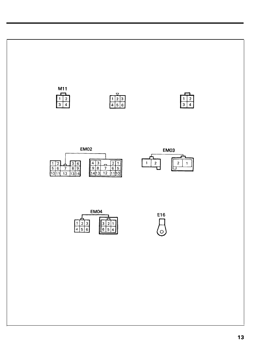
HORN
CONFIGURATION OF CONNECTORS
EM02
6 9
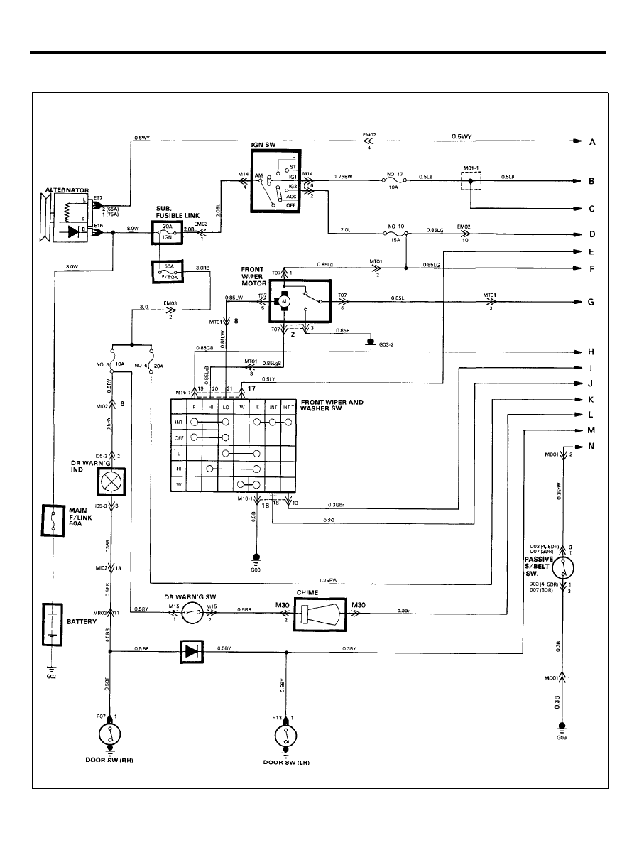
TIME AND ALARM CONTROL
CIRCUIT DIAGRAM
7 0
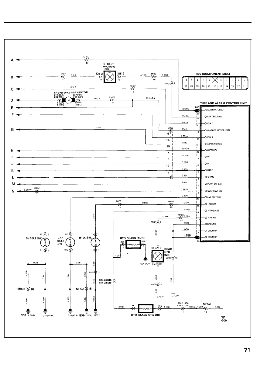
TIME AND ALARM CONTROL
CIRCUIT DIAGRAM
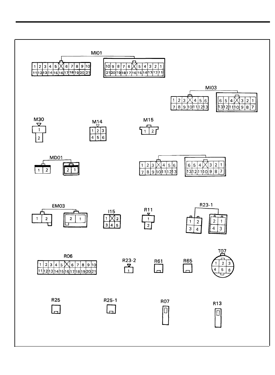
TIME AND ALARM CONTROL
CONFIGURATION OF CONNECTORS
MT01
7 2
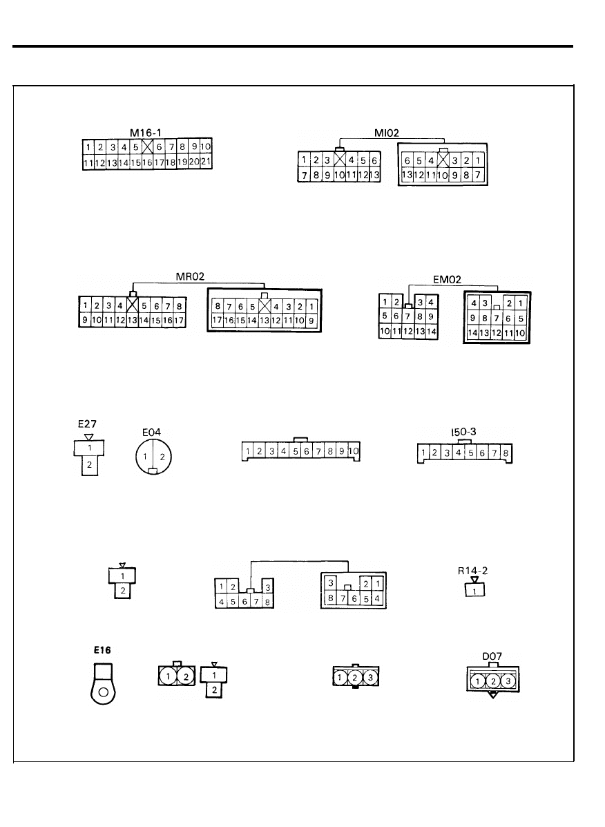
TIME AND ALARM CONTROL
CONFIGURATION OF CONNECTORS
R12
I05-2
R14-1
E17
D03
( 7 5 A ) ( 6 5 A )
7 3
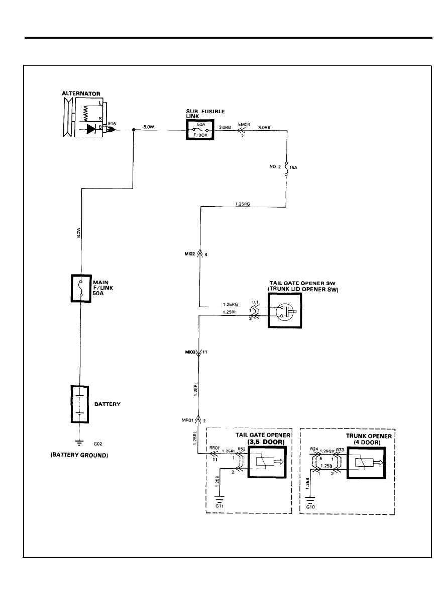
TAIL GATE (TRUNK LID) OPENER
CIRCUIT DIAGRAM
7 4
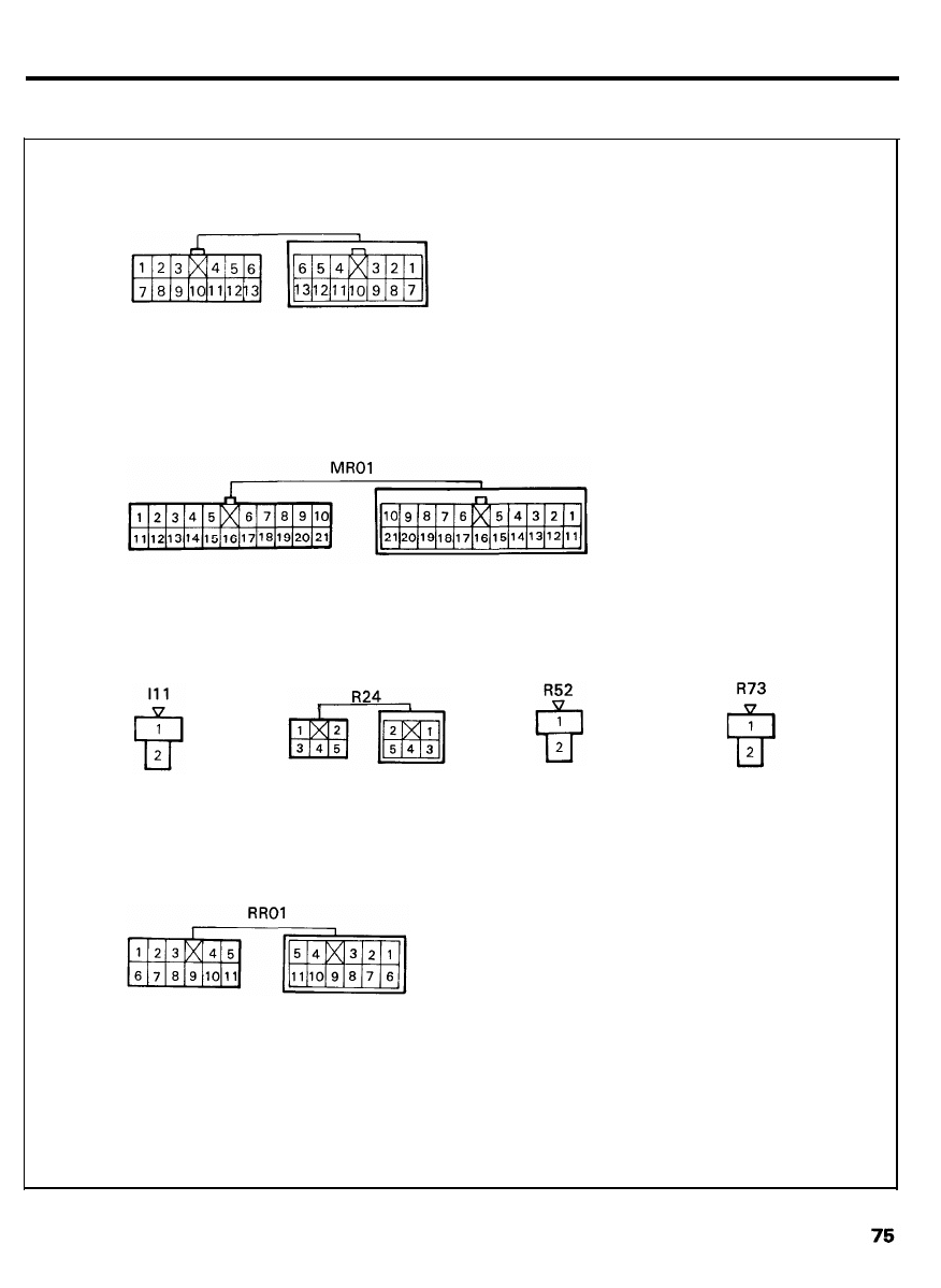
TAIL GATE (TRUNK LID) OPENER
CONFIGURATION OF CONNECTORS
Ml03
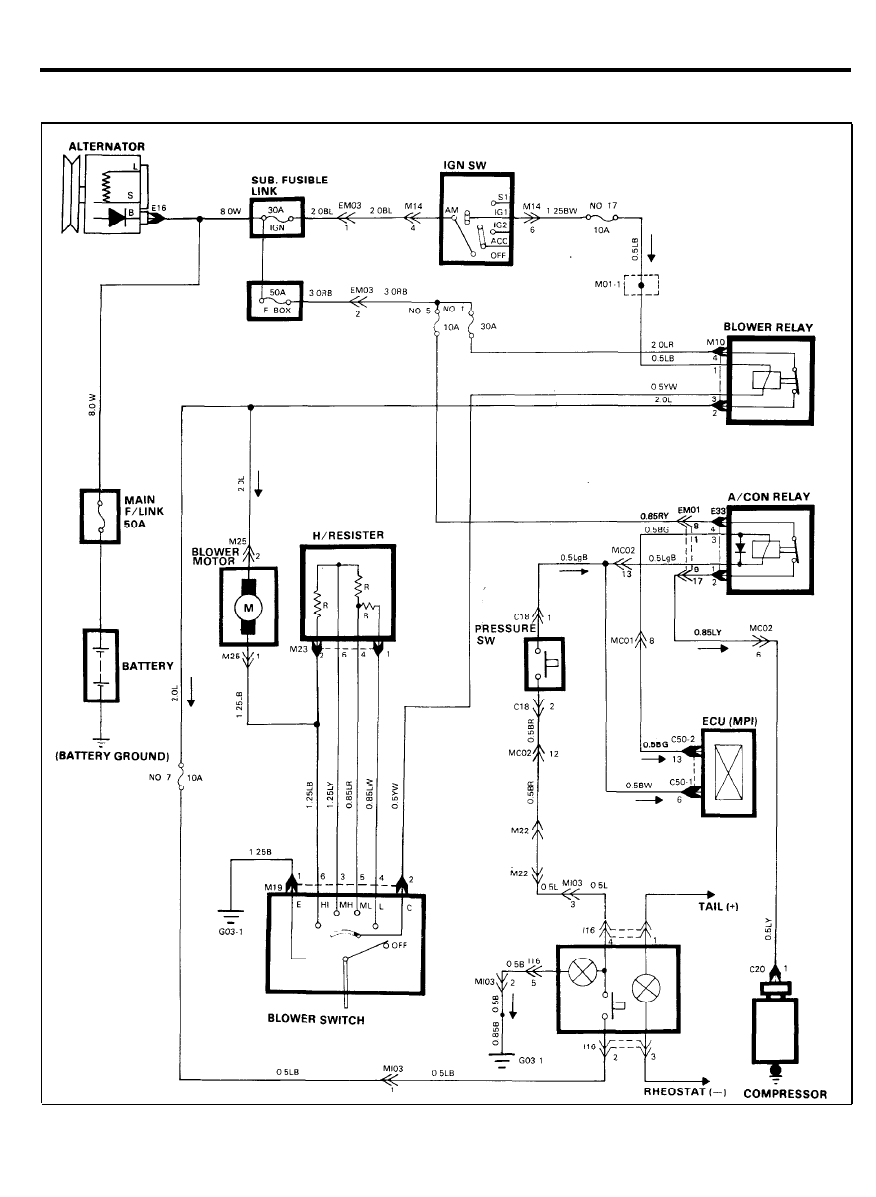
AIR CONDITIONER (MPI)
CIRCUIT DIAGRAM
7 6
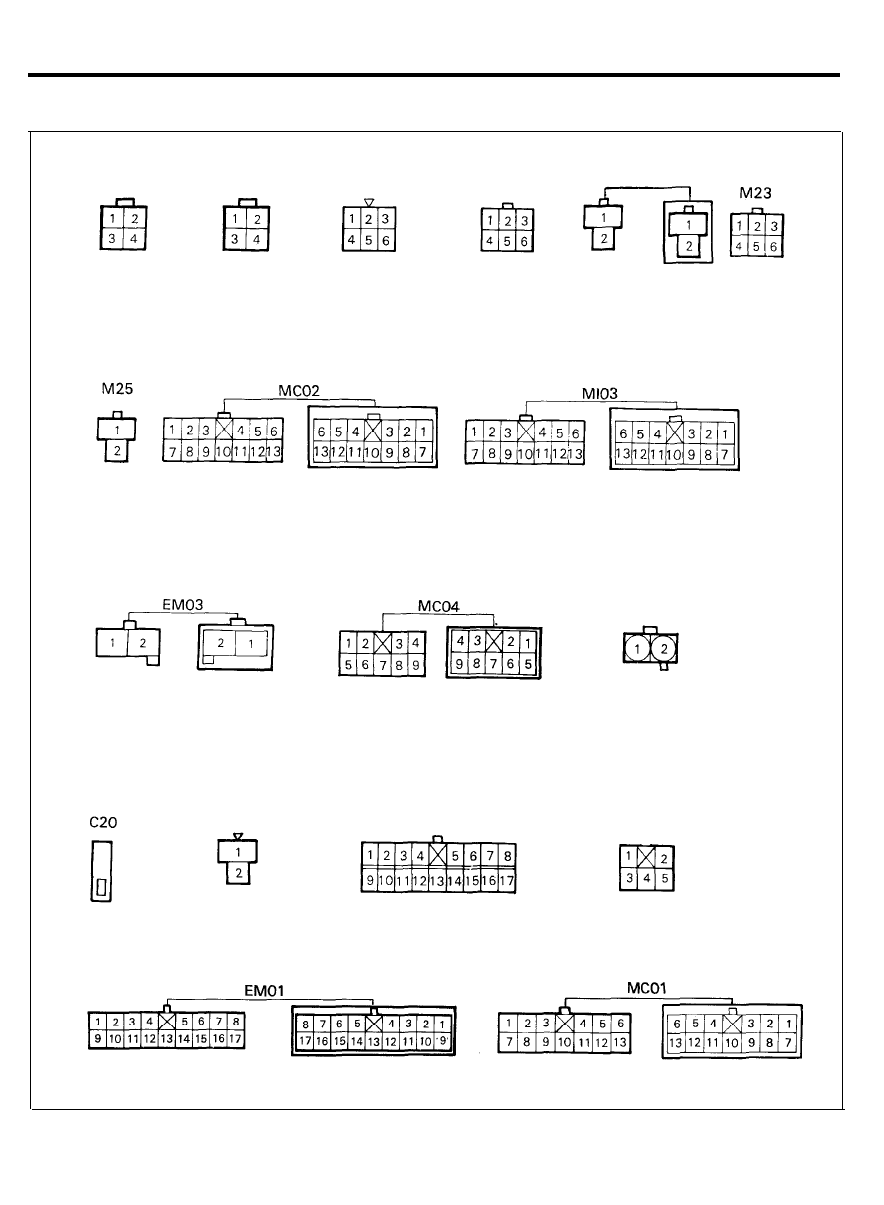
AIR CONDITIONER (MPI)
CONFIGURATION OF CONNECTORS
E33
M10
M14
C42
M19
M22
C60-1
C18
I16
77
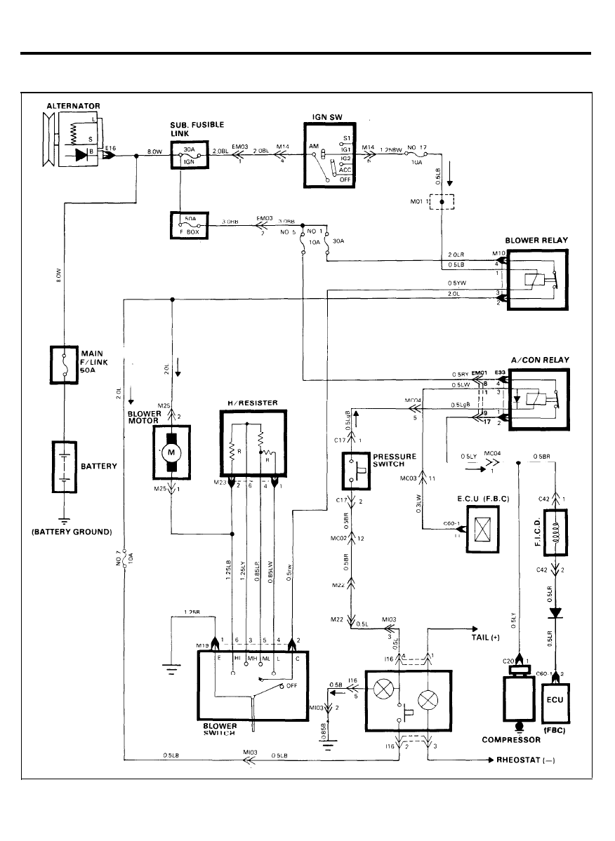
AIR CONDITIONER (FBC)
CIRCUIT DIAGRAM
78
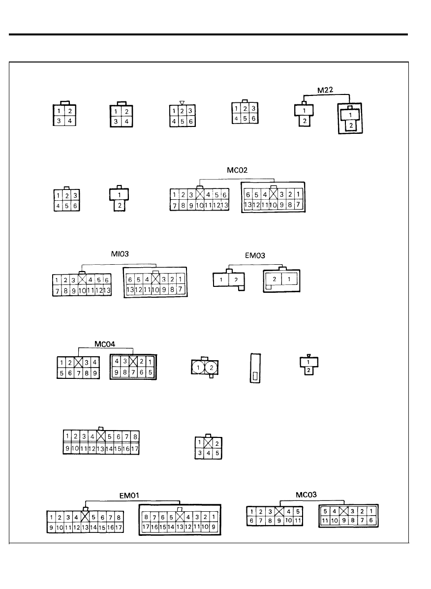
AIR CONDITIONER (FBC)
CONFIGURATION OF CONNECTORS
M09
M23
M10
M25
M14
M19
C60-1
C17
I16
C20
C42
7 9
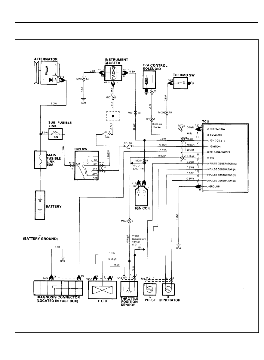
ELECTRONIC LOCK UP CONTROL (3-SPEED)
CIRCUIT DIAGRAM
8 0
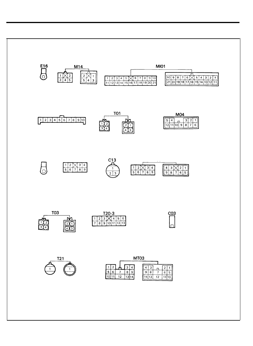
ELECTRONIC LOCK UP CONTROL (3-SPEED)
CONFIGURATION OF CONNECTORS
I05-2
C16
C60-2
MC04
81
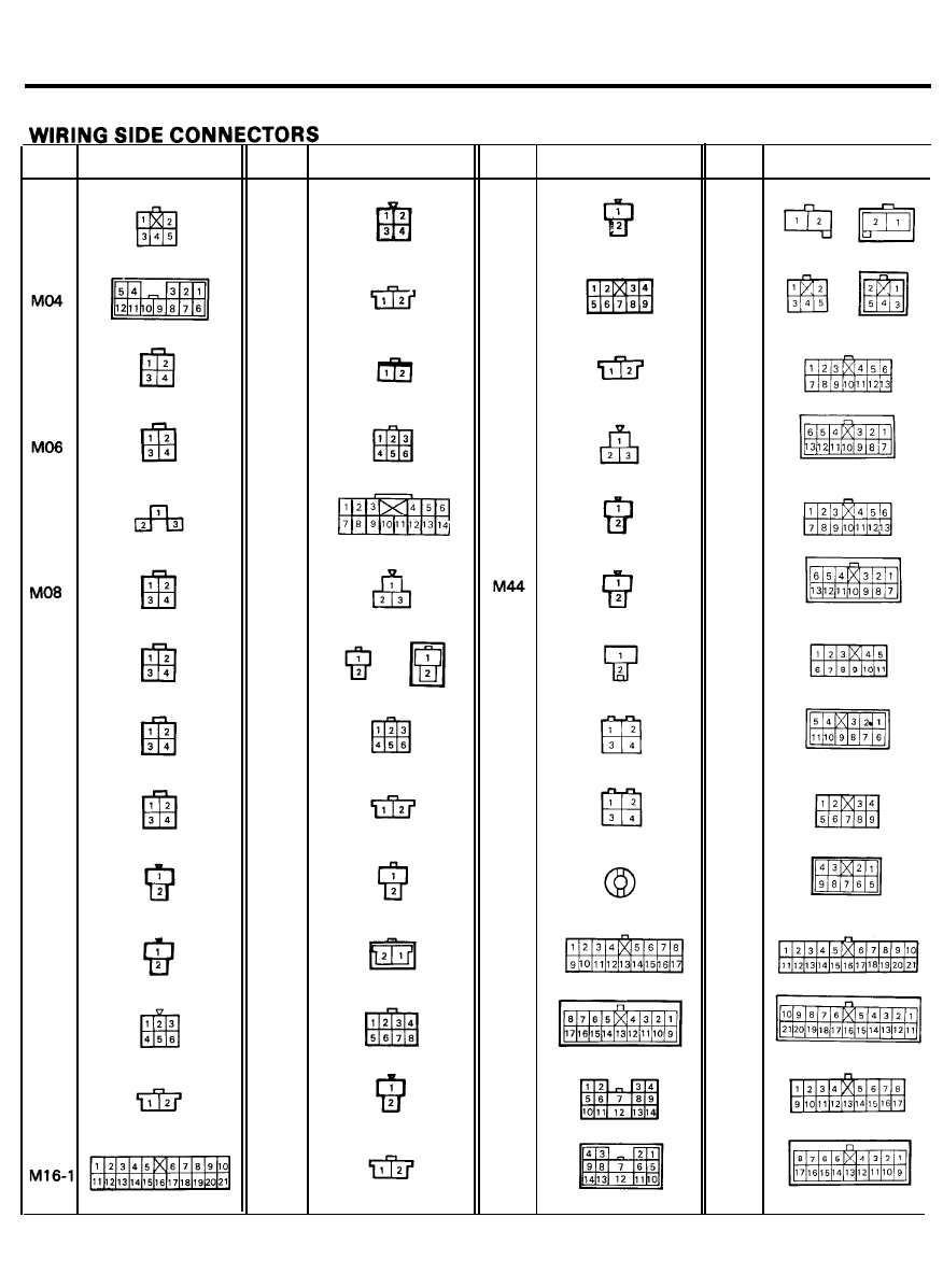
WIRING CONNECTORS
Symbol
M03
MO5
MO7
MO9
M10
M11
M12
M13
M14
M15
Terminal No.
Sybol
M16-2
M17
M18
M19
M20
M21
M22
M23
M24
M25
M26
M29
M30
M31
Terminal No.
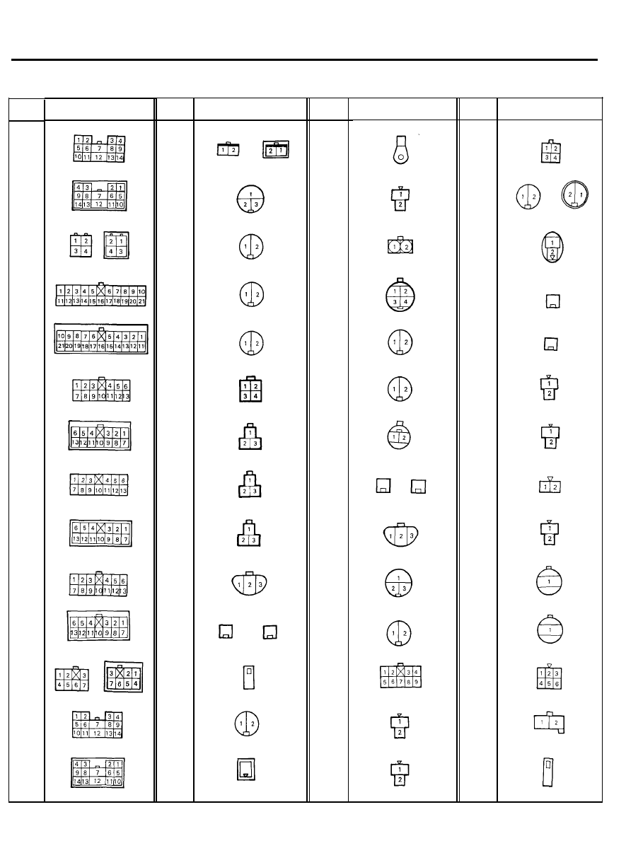
Smbol
Terminal No.
M32
M33
M41
M42
M43
M51
M61
M62
M71
EM01
EM02
Symbol
Terminal No.
EM03
EM04
MC01
MC02
MC03
MC04
MR01
MR02
8 2 A
Symbol
MR03
MR04
Ml01
MI02
Ml03
MT01
MT02
MT03
Terminal No.
Symbol
MD01
E02
E03
E04
E05
E06
E07
E08
E09
E10
E12
E13
E14
E15
Terminal No.
Symbol
Terminal No.
E16
E17
(65A)
E17
(75A)
E18
E18-1
E18-2
E19
E20
E21
E24
E25
E26
E27
E28
Symbol
Terminal No.
E33
ET01
C01
C02
C03
C04
C05
C06
C07
CO8
C09
C10
C11
C12
8 2 B
Symbol
C13
C16
C17
C18
C19
C20
C21
C22-1
C22-2
C22-3
C22-4
C23
C24
C25
Terminal No.
Symbol
C26
C27
C28
C29
C30
C31
C32
C33
C34
C35
C36
C37
C38
C39
Terminal No.
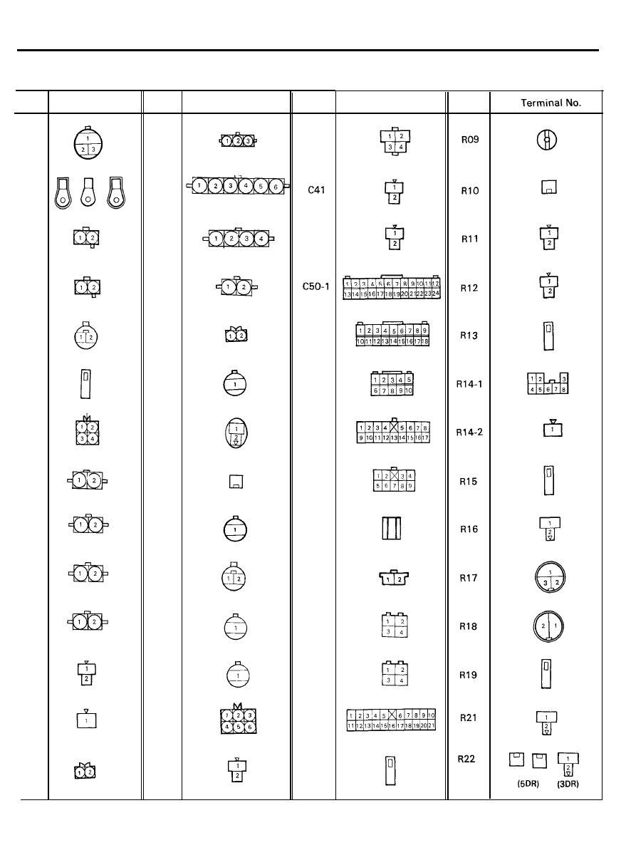
Symbol
C40
C42
C50-2
C50-3
C60-1
C60-2
C71
R03
R04
R05
R06
R07
Terminal No.
Symbol
8 2 C
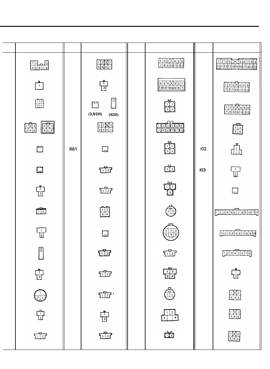
Symbol
R23-1
R23-2
R23-3
R24
R25
R25-1
R26
R27
R28
R29
R30
R31
R35
R36
Terminal No.
Symbol
R51
R52
R53
R54
R62
R63
R64
R65
R66
R71
R72
R73
R74
Terminal No.
Symbol
RR01
TO1
TO2
TO3
TO4
TO5
TO6
TO7
TO8
TO9
T10
T11
T13
Terminal No.
Symbol
T20-1
T20-2
T20-3
I01
I04
I05-1
I05-2
I05-3
I11
I12
I13
I15
Terminal No.
8 2 D
Symbol
I16
DO3
DO7
Terminal No.
8 2 E
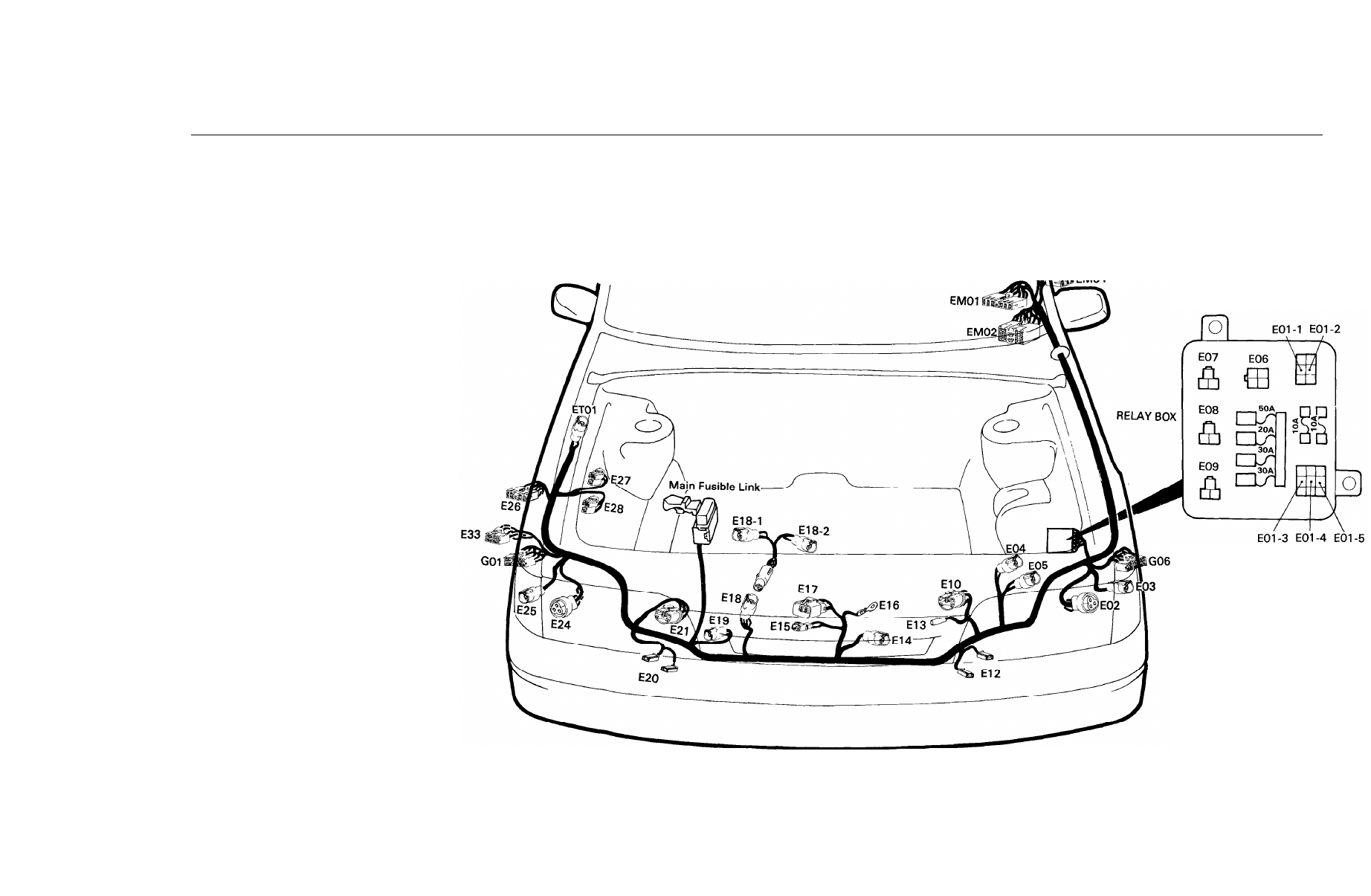
WIRING HARNESS LAYOUT
8 3 A
ENGINE WIRING HARNESS
E01-1
E01 -2
E01-3
E01-4
E01-5
E02
E03
E04
E05
E06
E07
E08
E09
E10
E12
E13
E14
E15
E16
E17
E18
E18-1
E18-2
E19
E20
E21
E24
E25
E26
E27
E28
E33
ET01
ET01
EM01
EM02
EM03
EM04
Joint Connector (Ignition)
Joint Connector (Head Lamp) (High)
Joint Connector (Tail Lamp) (LH)
Joint Connector (Head Lamp) (Low)
Joint Connector (Tail Lamp) (
RH
)
Turn Signal Lamp (LH)
Side Marker Lamp (LH)
Washer Motor (Front) (MPI)
Washer Motor (Rear) (MPI)
Head Lamp Relay
Condenser Fan Motor Relay
Radiator Fan Motor Relay (Low)
Radiator Fan Motor Relay (High)
Head Lamp (LH)
Horn (LH)
Power Steering Switch
Condenser Fan Motor
Oil Press Switch
Alternator (B+)
Alternator (S or L)
Radiator Fan Motor
Thermostat Switch
Resister
Receiver Dryer
Horn (RH)
Head Lamp (RH)
Turn Signal Lamp (RH)
Side Marker Lamp (RH)
Daytime Running Light Unit (Canada)
Washer Motor (Front) (FBC)
Washer Motor (Rear) (FBC)
A/C Relay
Back-up Switch Extension Harness (M/T)
Connection With T/A Control Harness (A/T)
Connection With Main Harness
Connection With Main Harness
Connection With Main Harness
Connection With Main Harness
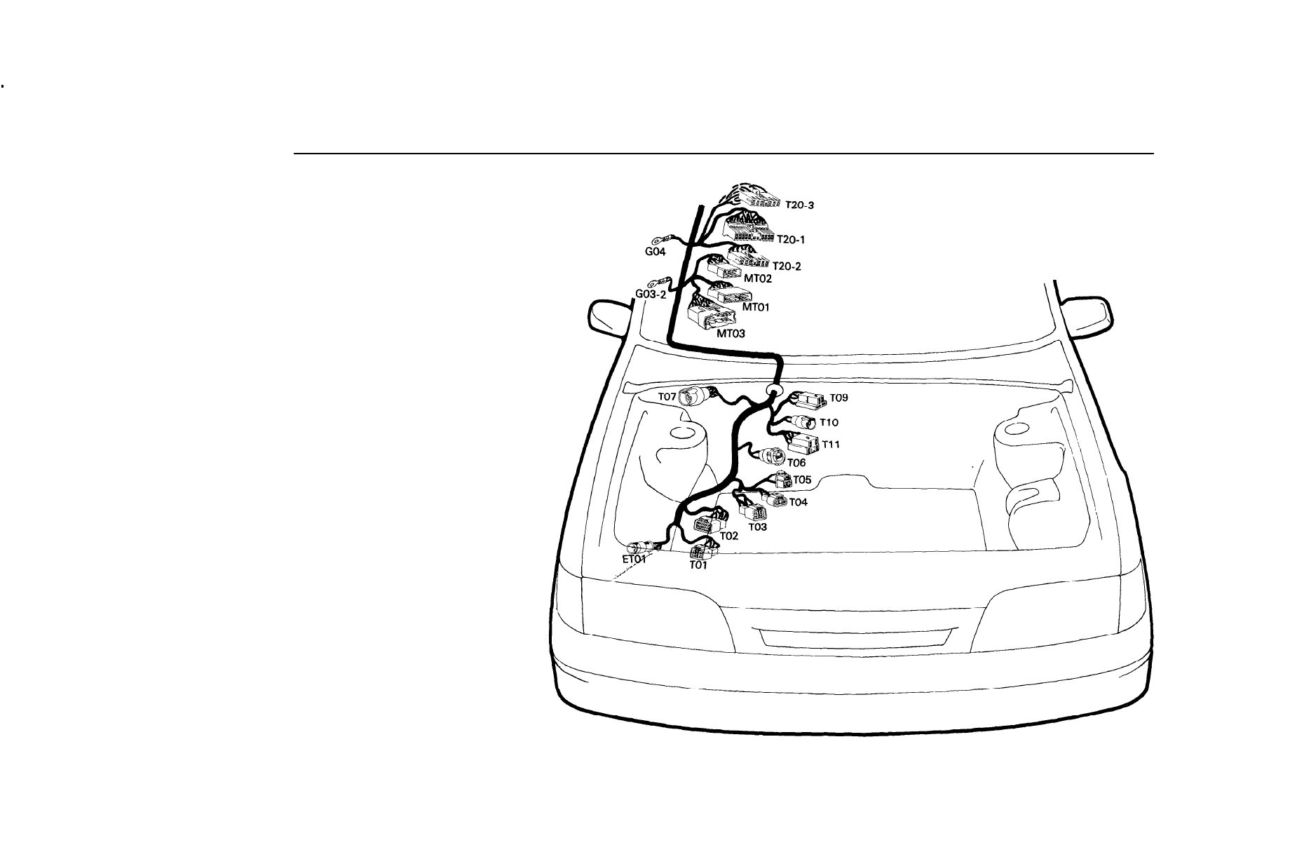
T/A CONTROL WIRING HARNESS
TO1
T/A Solenoid
TO2
Inhibitor Switch
TO3
Pulse Generator
T04
Oil Temperature Sensor
T05
Kick Down Switch
TO6
Brake Fluid Sensor
TO7
Wiper Motor (FRT)
TO9
Electronic Choke Relay
T10
Vacuum Switch
T11
lnmani Heater Relay
T20-1
Electronic Lock Up Control Unit (4-speed)
T20-2
Electronic Lock Up Control Unit (4-speed)
T20-3
MT01
Electronic Lock Up Control Unit (3-speed)
Connection With Main Harness
MT02
Connection With Main Harness
MT03
Connection With Main Harness (A/T)
ET01
Connection With Engine Harness
83B
WIRING HARNESS LAYOUT
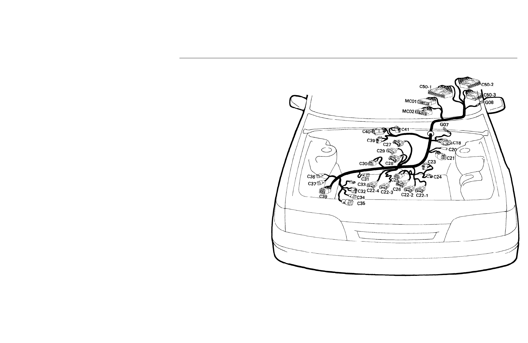
8 4 A
E.C.U WIRING HARNESS (M.P.I)
C18
C20
C21
C22-1
C22-2
C22-3
C22-4
C23
C24
C25
C26
C27
C28
C29
C30
C31
C32
C33
C34
C35
C36
C37
C38
C39
C40
C41
MC01
MC02
C50-1
C50-2
C50-3
Pressure Switch
Compressor
Distributor
Injector #l
Injector #2
Injector #3
Injector #4
Noise Filter
Condenser
Ignition Coil
Power Transistor
Motor Position Sensor
Throttle Position Sensor
Idle Speed Control Motor
E.G.R Temperature Sensor
Start Solenoid
Water Temperature Sensor
Water Temperature Gauge
Oxygen Sensor
Oxygen Sensor (California only)
Fuel Pump Checker
Electronic Spark Timing Adjustment
Air Flow Sensor
Purge Solenoid
Relay With Diode
E.G.R Solenoid
Connection With Main Harness
Connection With Main Harness
Multi Point Injection Control Unit
Multi Point Injection Control Unit
Multi Point Injection Control Unit
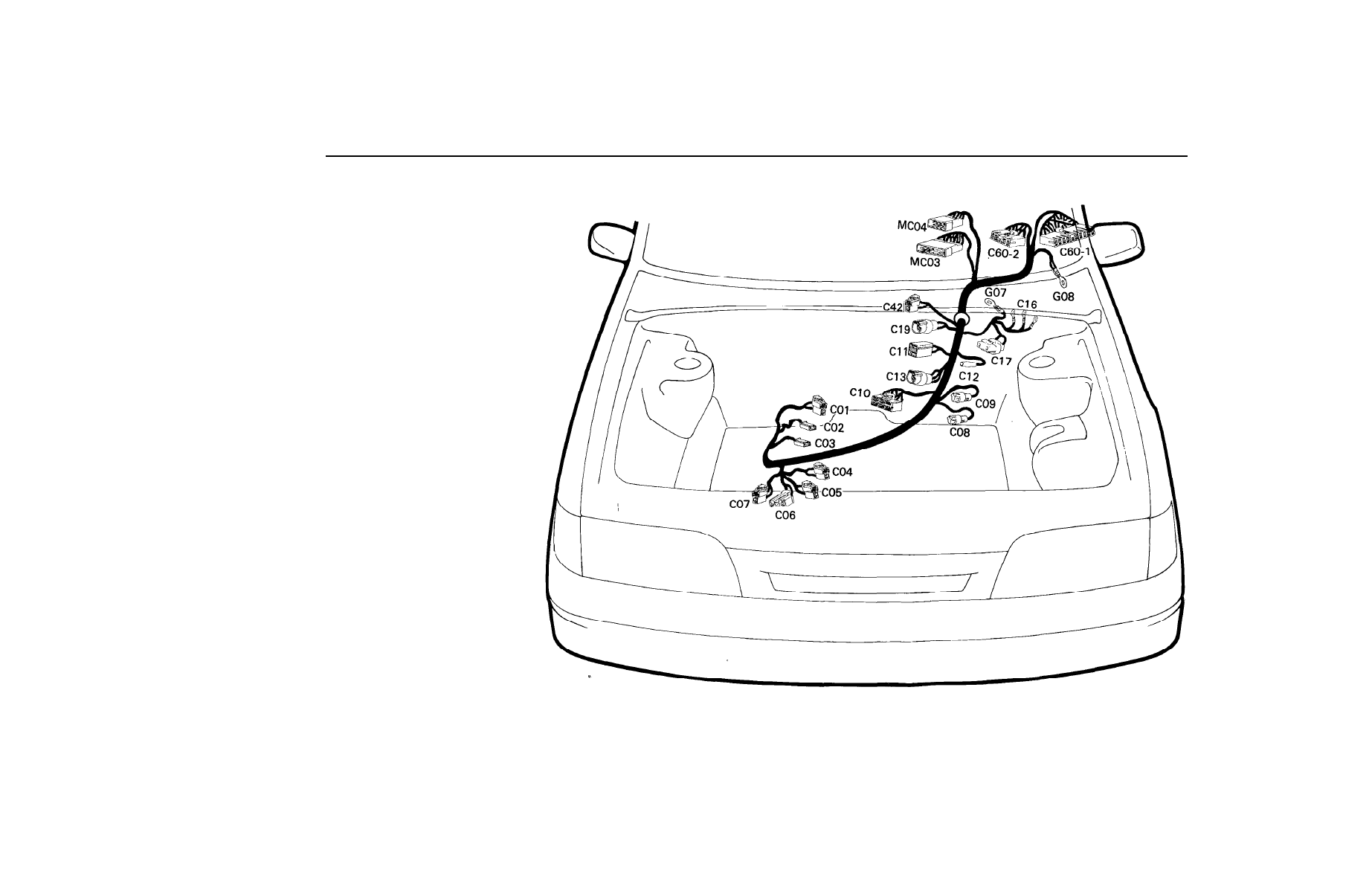
8 4 B
E.C.U WIRING HARNESS (F.B.C)
C01
C02
C03
C04
C05
CO6
C07
CO8
C09
C10
C11
C12
C13
C16
C17
C19
C42
C60-1
C60-2
MC03
MC04
Water Temperature Sensor
Water Temperature Gauge
Thermo Switch
Idle Up Solenoid
Distributor Solenoid
Secondary Air Solenoid
Cold Spark Advance Solenoid
Oxygen Sensor
Start Solenoid
Carburator
Cold Heater
Compressor
Throttle Position Sensor
Ignition Coil
Pressure Switch
Oxygen Sensor Checker
F.I.C.D
Feedback Carburator Control Unit
Feedback Carburator Control Unit
Connection With Main Harness
Connection With Main Harness
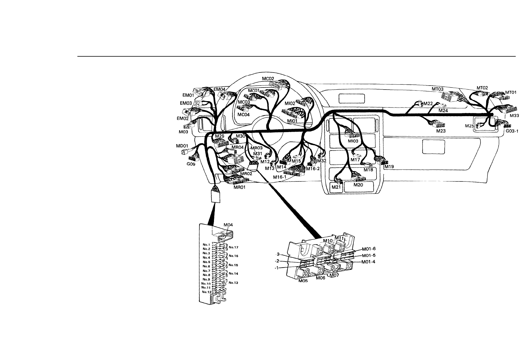
WIRING HARNESS LAYOUT
8 5 A
MAIN WIRING HARNESS
M01-1
M01-2
M01-3
M01-4
M01-5
M01-6
M03
M04
M05
M06
M07
M10
M11
M12
M13
M14
M15
M16-1
M16-2
M17
M18
M19
M20
M21
M22
M23
M24
M25
M29
M30
M31
M32
M33
EM01
EM02
EM03
EM04
Joint Connector (IGN. 1)
Joint Connector (Turn Signal Lamp) (RH)
Joint Connector (Turn Signal Lamp) (LH)
Joint Connector (Rheostat)
Joint Connector (Tail Lamp) (LH)
Joint Connector (Tail Lamp) (RH)
Roof Wiring Connector
M.U.T checker
Start Relay
Idle Up Relay
Flasher Unit
Blower Relay
Tail Lamp Relay
Stop Switch
Accelerator Switch
Ignition Switch
Door Warning Switch
Multifunction Switch
Multifunction Switch
Heater Control Illumination
Blower Actuator Extension Connector
Blower Switch
Audio
Cigarette Lighter
Thermo Switch
Heater Resister
Speaker Extention Wiring Connector
Blower Motor
Electronic Control Unit Relay
Chime Bell
Ignition Lock Switch
Interlock Solenoid
A/T Key Lock Control Unit
Connection With Engine Harness
Connection With Engine Harness
Connection With Engine Harness
Connection With Engine Harness
M01
M01
M01
MR01
MR02
MR03
MR04
MD01
MC01
MC02
MC03
MC04
Ml01
Ml02
Ml03
MT01
MT02
MT03
Connection With Floor Harness
Connection With Floor Harness
Connection With Floor Harness
Connection With Floor Harness
Connection With Door Harness (LH) (Front)
Connection With E.C.U Harness (MPI)
Connection With E.C.U Harness (MPI)
Connection With E.C.U Harness (FBC)
Connection With E.C.U Harness (FBC)
Connection With Crash Pad Harness
Connection With Crash Pad Harness
Connection With Switch Extention Harness
Connection With T/A Control Harness
Connection With T/A Control Harness (FBC)
Connection With T/A Control Harness (A/T)
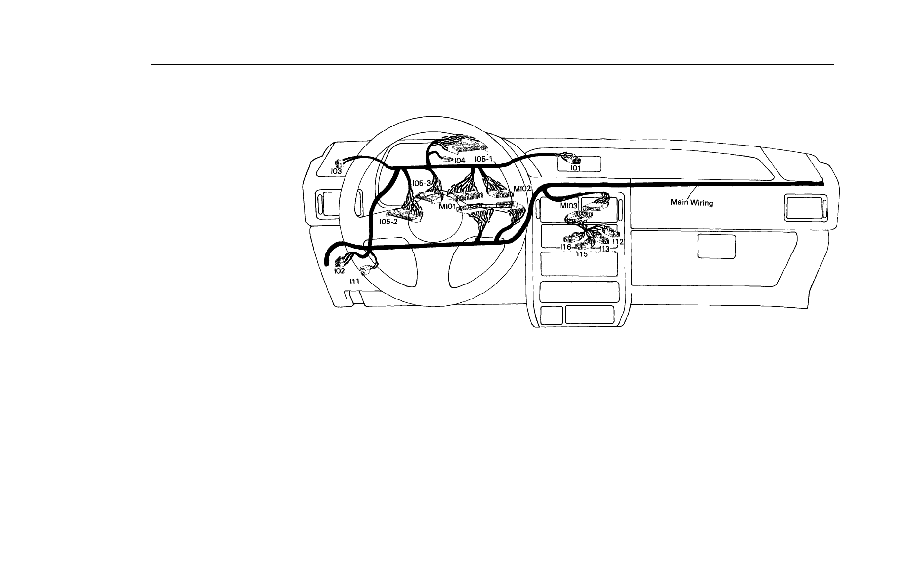
CRASH PAD WIRING HARNESS,
SWITCH EXTENSION WIRING HARNESS
I01
I02
I03
I04
I05-1
I05-2
I05-3
I11
I12
I13
I15
I16
Ml01
Ml02
Ml03
Clock
Rheostat
Speaker (FRT, LH)
Reed Switch
Cluster
Cluster
Cluster
Tail Gate (Trunk Lid) Opener Switch
Washer Switch (Rear)
Wiper Switch (Rear)
Heated Switch
A/C Switch
Connection With Main Harness
Connection With Main Harness
Connection With Main Harness
8 5 B
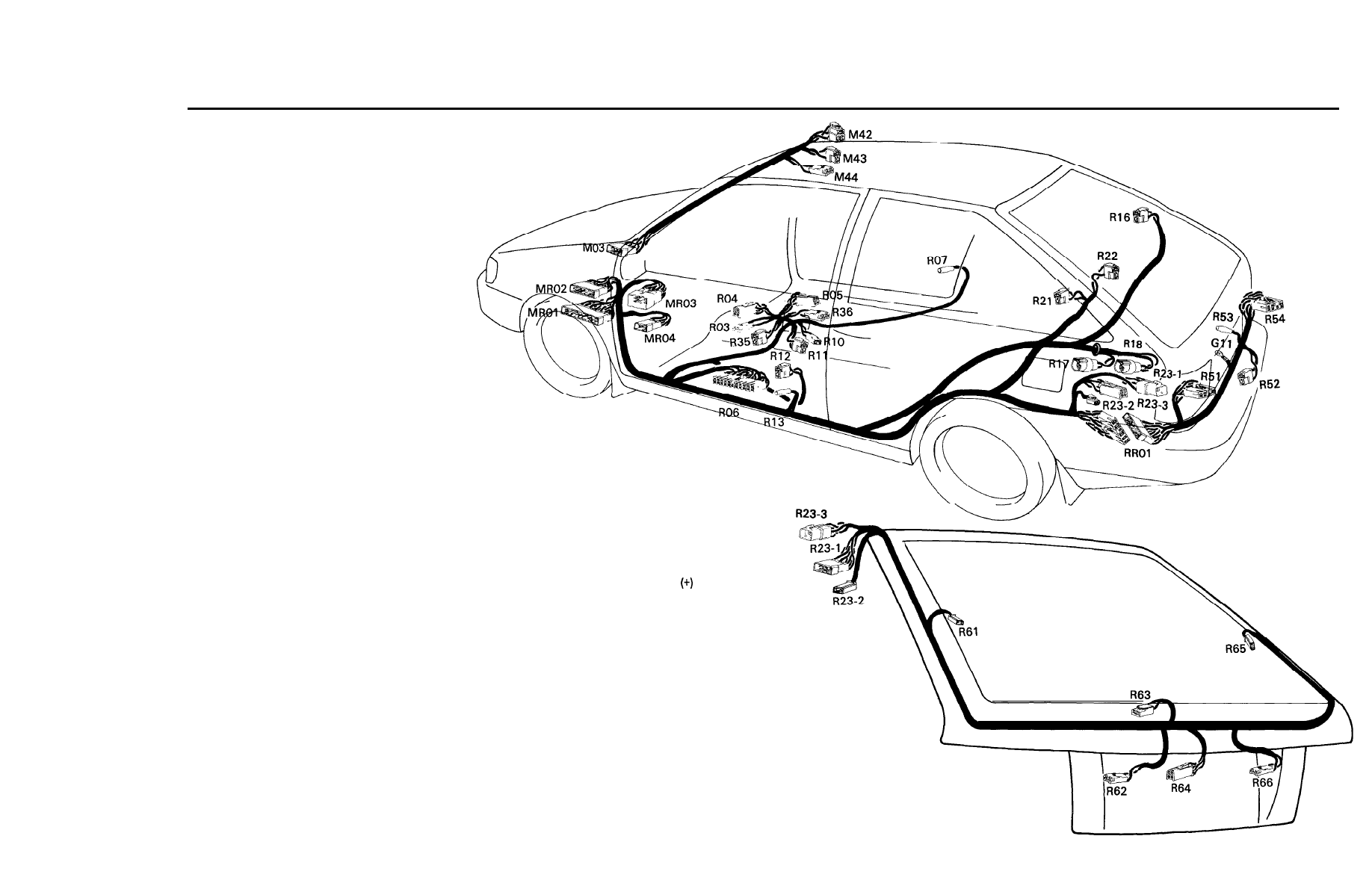
WIRING HARNESS LAYOUT
8 6 A
FLOOR WIRING HARNESS (3 DOOR)
R03
R04
R05
R06
R07
R10
R11
R12
R13
R16
R17
R18
R21
R22
R23-1
R23-2
R23-3
R35
R36
R51
R52
R53
R54
M42
M43
M44
MR01
MR02
MR03
MR04
RR01
M03
A/T Illumination
Over Drive Switch
E.C.T Switch
Time and Alarm Control Unit
Door Switch (FRT, RH)
Parking Brake Switch
Seat Belt Switch
Lap Belt Switch
Door Switch (FRT, LH)
Speaker (RR, RH)
Fuel Sender Wiring Connector
Fuel Pump
Speaker (RR, LH)
Luggage Lamp
Connection With Tail Gate Harness
Connection With Tail Gate Harness
Connection With Tail Gate Harness
A/T Solenoid
P/Position Switch
Rear Combination Lamp (LH)
Tail Gate Opener
Luggage Lamp Switch
Rear Combination Lamp (RH)
Room Lamp
Sun Roof Switch
Sun Roof Motor
Connection With Main Harness
Connection With Main Harness
Connection With Main Harness
Connection With Main Harness
Connection With Rear Floor Harness
Connection With Main and Roof Harness
TAIL GATE WIRING HARNESS (3 DOOR)
R61
R62
R63
R64
R65
R66
R23-1
R23-2
R23-3
Heated Glass
License Plate Lamp (LH)
High Mounted Stop Lamp
Wiper Motor (Rear)
Heated Glass (-)
License Plate Lamp (RH)
Connection With Floor Harness
Connection With Floor Harness
Connection With Floor Harness
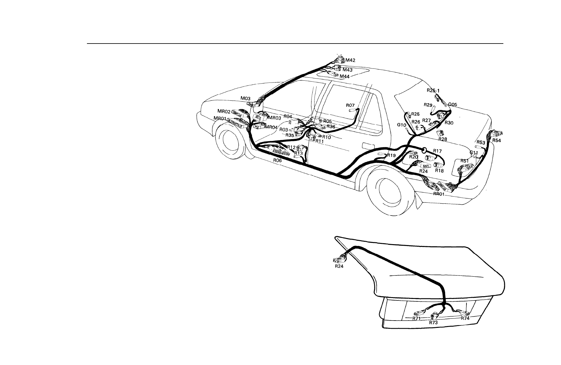
FLOOR WIRING HARNESS (4 DOOR)
R03
R04
R05
R06
R07
R10
R11
R12
R13
R17
R18
R19
R24
R25
R25-1
R26
R27
R28
R29
R30
R35
R36
R51
R53
R54
M42
M43
M44
MR01
MR02
MR03
MR04
RR01
M03
A/T Illumination
Over Drive Switch
E.C.T Switch
Time and Alarm Control Unit
Door Switch (FRT, RH)
Parking Brake Switch
Seat Belt Switch
Lap Belt Switch
Door Switch (FRT, LH)
Fuel Sender Wiring Connector
Fuel Pump
Door Switch (RR, LH)
Connection With Trunk Lid,Harness
Heated Glass (+)
Heated Glass (-)
Speaker (RR, LH)
High Mounted Stop Lamp
Luggage Lamp
Door Switch (RR, RH)
Speaker (RR, RH)
A/T Solenoid
P/Position Switch
Rear Combination Lamp (LH)
Luggage Lamp Switch
Rear Combination Lamp (RH)
Room Lamp
Sun Roof Switch
Sun Roof Motor
Connection With Main Harness
Connection With Main Harness
Connection With Main Harness
Connection With Main Harness
Connection With Rear Floor Harness
Connection With Main and Roof Harness
TRUNK LID WIRING HARNESS
R24
Connection With Floor Harness
R71
License Plate Lamp (LH)
R73
Trunk Opener
R74
License Plate Lamp (RH)
8 6 B
WIRING HARNESS LAYOUT
8 7 A
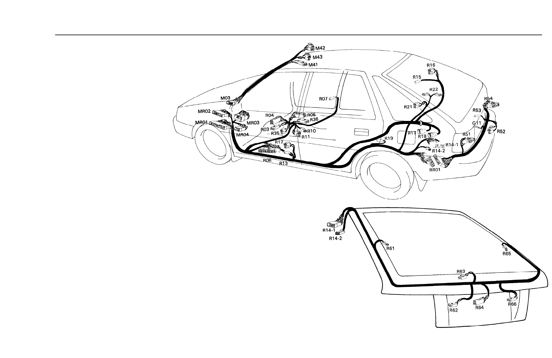
FLOOR WIRING HARNESS (5 DOOR)
R03
A/T Illumination
R04
Over Drive Switch
R05
E.C.T Switch
R06
Time and Alarm Control Unit
R07
Door Switch (FRT, RH)
R10
Parking Brake Switch
R11
Seat Belt Switch
R12
Lap Belt Switch
R13
Door Switch (FRT, LH)
R14-1
Connection With Tail Gate Harness
R14-2
Connection With Tail Gate Harness
R15
Door Switch (RR, RH)
Speaker (RR, RH)
Fuel Sender Wiring Connector
Fuel Pump
Door Switch (RR, LH)
R16
R17
R18
R19
R21
R22
R35
R36
R51
R52
R53
R54
M42
M43
M44
MR01
MR02
MR03
MR04
RR01
M03
Speaker (RR, LH)
Luggage Lamp
A/T Solenoid
P/Position Switch
Rear Combination Lamp (LH)
Tail Gate Opener
Luggage Lamp Switch
Rear Combination Lamp (RH)
Room Lamp
Sun Roof Switch
Sun Roof Motor
Connection With Main Harness
Connection With Main Harness
Connection With Main Harness
Connection With Main Harness
Connection With Rear Floor Harness
Connection With Main and Roof Harness
TAIL GATE WIRING HARNESS (5 DOOR)
R61
R62
R63
R64
R65
R66
R14-1
R14-2
Heated Glass (+)
License Plate Lamp (LH)
High Mounted Stop Lamp
Wiper Motor (Rear)
Heated Glass (-)
License plate lamp (RH)
Connection With Floor Harness
Connection With Floor Harness
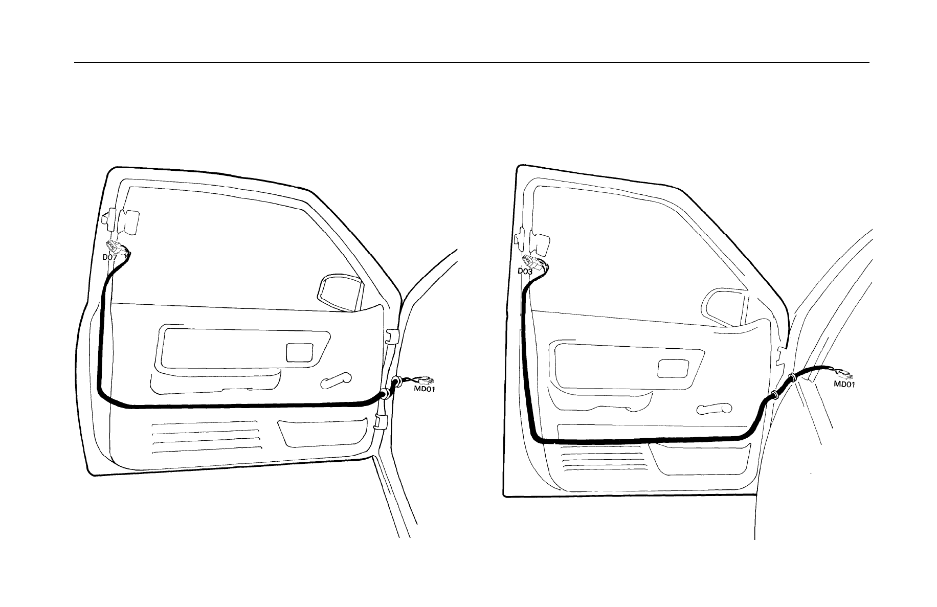
DOOR WIRING HARNESS (3
DOOR)
FRONT DOOR WIRING HARNESS (4/5 DOOR)
DO7
Seat Belt Switch (Passive)
MD01
Connection With Main Harness
DO3
MD01
Seat Belt Switch (Passive)
Connection With Main Harness
8 7 B
Wyszukiwarka
Podobne podstrony:
CEI 61400 22 Wind turbine generator systems Required Design Documentation
ELECTRICAL WIRING ROUTING
How to Use the Electrical Wiring Diagram
Overall Electrical Wiring Diagram
Popular Mechanics Repairing Electrical Wiring
Overall Electrical Wiring Diagram
wykład 1- 22.02, WSA, konstytucyjny system organów państwowych, wykłady, wykład 1
M39a Body Wiring System
CEI 61400 22 Wind turbine generator systems Required Design Documentation
US Patent 514,972 Electric Railway System
96ZJ 8N ELECTRICALLY HEATED SYSTEMS
Electrical Wiring Diagram (AE86 sunroof)
b3 97 electrical wiring
Overall Electrical Wiring Diagram
więcej podobnych podstron