NMS-KD-0017-en
N3000-IMC and -ISC
User Manual
Version 01.03
2 / 20
NORIS Marine Systems GmbH & Co. KG, Muggenhofer Strasse 95, D - 90429 Nuremberg
Phone: +49 911 32 01-0, Fax: +49 911 32 01-150, info@noris-automation.com, www.noris-automation.com
NMS-KD-0017-en
Version 01.03
19/11/2009 - DHI
N3000-IMC and -ISC
User Manual
Document name
[ NMS-KD-0017-en-V01.03_N3000-IMC and -ISC User Manual.docx ]
Scope of document
Document applies for:
no declaration
List of Changes
Document Changes
Change Order
Version Date
Modified
Chapters
Author
Reasons for Changes
Initiator
V01.00
12.01.2009
all
DHI
- - -
DHI
V01.01
29.01.2009
3.1, 3.2
DHI
Location frequency inputs added
DHI
V01.02
11.05.2009
all
DHI
div. correction (formality)
ALE
V01.03
19.11.2009
2.2.1, 2.2.2
DHI
Channels of X10 corrected
ALE
Printed in Germany
© 2009 NORIS Marine Systems GmbH & Co. KG
This publication including any and all of its parts is copyrighted. Any exploitation or utilization of the text shall require prior
written approval by NORIS Marine Systems GmbH & Co. KG. This provision applies in particular to the reproduction,
distribution, editing, translation, storage and / or processing of the material in electronic systems, including data bases and
online services. Changes reserved.

3 / 20
NORIS Marine Systems GmbH & Co. KG, Muggenhofer Strasse 95, D - 90429 Nuremberg
Phone: +49 911 32 01-0, Fax: +49 911 32 01-150, info@noris-automation.com, www.noris-automation.com
NMS-KD-0017-en
Version 01.03
19/11/2009 - DHI
N3000-IMC and -ISC
User Manual
Table of Contents
Symbols used in this document ...................................................................................................................... 4
1.
General safety requirements ..................................................................................... 5
2.
Overview ................................................................................................................... 6
2.1
Subject of this document ................................................................................................... 6
2.2
Device structure ................................................................................................................ 6
2.2.1
N3000‐IMC connections side .......................................................................................................... 6
2.2.2
N3000‐ISC connections side ............................................................................................................ 8
3.
Functional description ............................................................................................... 9
3.1
N3000‐IMC standard equipment ........................................................................................ 9
3.2
N3000‐ISC standard equipment ......................................................................................... 9
3.3
N3000‐IMC and N3000‐ISC plug‐in modules ..................................................................... 10
3.3.1
Universal analogue input module ................................................................................................. 10
3.3.2
Universal analogue output module ............................................................................................... 10
3.3.3
Digital input/output module ......................................................................................................... 11
3.4
Status LEDs on the connectors side of I/O boxes .............................................................. 11
3.4.1
Channel status LEDs indicator code .............................................................................................. 12
3.4.2
System status LED indicator code ................................................................................................. 14
3.4.3
CANbus LEDs indicator code ......................................................................................................... 15
3.5
Fault reports and fault clearing ........................................................................................ 16
4.
Technical Data ......................................................................................................... 18
Table of figures .............................................................................................................................................. 20
4 / 20
NORIS Marine Systems GmbH & Co. KG, Muggenhofer Strasse 95, D - 90429 Nuremberg
Phone: +49 911 32 01-0, Fax: +49 911 32 01-150, info@noris-automation.com, www.noris-automation.com
NMS-KD-0017-en
Version 01.03
19/11/2009 - DHI
N3000-IMC and -ISC
User Manual
Symbols used in this document
NOTICE
Important notes are following.
CAUTION
ATTENTION! Very important instructions are
following to avoid damage to property.
READ
In this section you find a reference to further
information in other documents.

5 / 20
NORIS Marine Systems GmbH & Co. KG, Muggenhofer Strasse 95, D - 90429 Nuremberg
Phone: +49 911 32 01-0, Fax: +49 911 32 01-150, info@noris-automation.com, www.noris-automation.com
NMS-KD-0017-en
Version 01.03
19/11/2009 - DHI
N3000-IMC and -ISC
User Manual
1. General safety requirements
Qualification of the staff and intended use
All devices and system components shall only be used for their intended use.
Installation, operation, maintenance and repair shall only be performed by qualified and
authorised staff.
Safety requirements for the start-up
Before starting up the system you must install all devices and system components correctly in
accordance to the appropriate advices and specifications.
Before starting up you have to finish all maintenance and repair work.
Safety requirements for the operation
The operator has to be familiar with the operation of the system and all of its components.
The operator must know the effects of any action to be performed by him.
If the system identifies or announce an alarm, appropriate countermeasures shall be taken
immediately to clear the fault.
The system and all of its components must be completely functional to ensure the correct
operation of the system. Appropriate countermeasures shall be taken immediately, if the
system or one of its components shows any failure.
NOTICE
The whole staff which is involved in installation,
operation, maintenance and repair should pay
attention to the advices in this section and read
them attentively.
6 / 20
NORIS Marine Systems GmbH & Co. KG, Muggenhofer Strasse 95, D - 90429 Nuremberg
Phone: +49 911 32 01-0, Fax: +49 911 32 01-150, info@noris-automation.com, www.noris-automation.com
NMS-KD-0017-en
Version 01.03
19/11/2009 - DHI
N3000-IMC and -ISC
User Manual
2. Overview
2.1 Subject of this document
The subject of this document are the N3000-IMC and N3000-ISC I/O boxes equipped
with hardware channels.
This document is intended for technicians and service personnel who work on a N3000
system.
This document contains:
o
a description of I/O boxes and their connections,
o
the fault reports that can be produced by I/O boxes,
o
possible means of clearing faults.
2.2 Device
structure
The I/O box is available in a master version (type N3000-IMC) and in a slave version
(type N3000-ISC):
o
N3000-IMC: independent master unit with an internal slave unit,
o
N3000-ISC: an independently operating slave unit subordinate to a master unit.
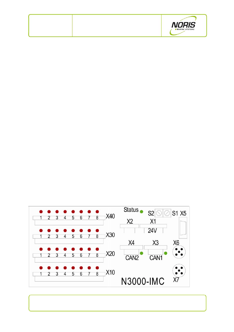
2.2.1 N3000-IMC
connections
side
Fig. 1: N3000-IMC connections side
7 / 20
NORIS Marine Systems GmbH & Co. KG, Muggenhofer Strasse 95, D - 90429 Nuremberg
Phone: +49 911 32 01-0, Fax: +49 911 32 01-150, info@noris-automation.com, www.noris-automation.com
NMS-KD-0017-en
Version 01.03
19/11/2009 - DHI
N3000-IMC and -ISC
User Manual
Position
Description
X1
Operating voltage: 18 … 32 V DC,
U
nom
= 24 V DC; in duplicate: alternate sources (connect through other units).
X2
Current-limited voltage source as power supply for sensors connected to this I/O box.
X3
CANbus 1 with status LED.
X4
CANbus 2 with status LED.
X5
RS232, RS422, RS485 combination interface
X6, X7
iBus (= internal bus) for connecting other devices within a CAN node.
X10
Sensor / actuator connections (4 binary inputs and 4 relay circuit outputs, each with a status
LED).
X20
8 connections, each with a status LED, for analogue/binary sensors and actuators.
X30
8 connections, each with a status LED, for analogue/binary sensors and actuators.
X40
8 connections, each with a status LED, for analogue/binary sensors and actuators.
S1
Rotary switch for setting the CANbus address; units digit, in HEX.
S2
Rotary switch for setting the CANbus address; tens digit, in HEX.
Status
Status LED:
green
= I/O box ready
flashing green/yellow = isolation fault to the housing
red
= boot mode or device inoperable fault
8 / 20
NORIS Marine Systems GmbH & Co. KG, Muggenhofer Strasse 95, D - 90429 Nuremberg
Phone: +49 911 32 01-0, Fax: +49 911 32 01-150, info@noris-automation.com, www.noris-automation.com
NMS-KD-0017-en
Version 01.03
19/11/2009 - DHI
N3000-IMC and -ISC
User Manual
2.2.2 N3000-ISC
connections
side
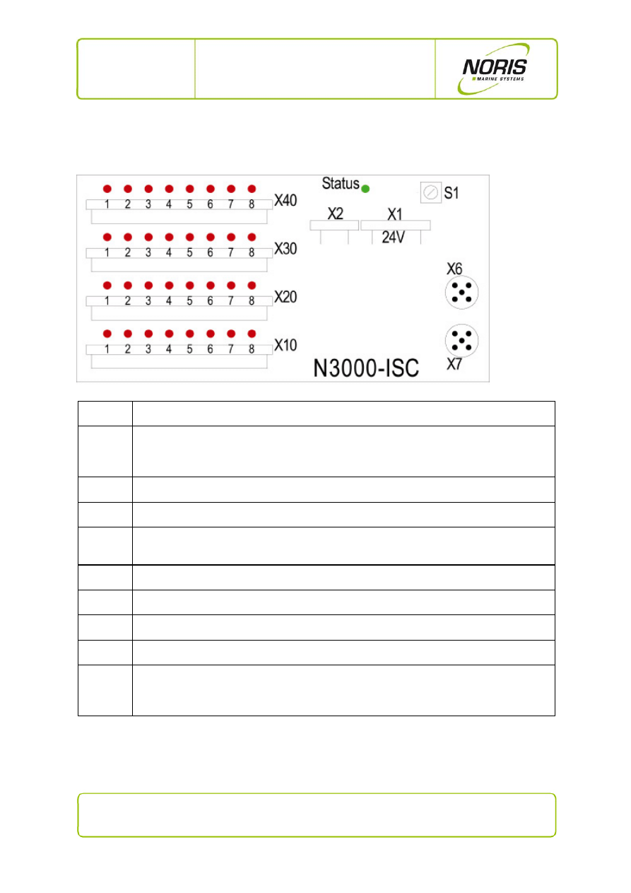
Fig. 2: N3000-ISC connections side
Position
Description
X1
Operating voltage: 18 … 32 V DC,
U
nom
= 24 V DC; in duplicate: alternate sources (connect through other units).
X2
Current-limited voltage source as power supply for sensors connected to this I/O box.
X6, X7
iBus (= internal bus) for connecting other devices within a CAN node.
X10
Sensor / actuator connections (4 binary inputs and 4 relay circuit outputs, each with a status
LED).
X20
8 connections, each with a status LED, for analogue/binary sensors and actuators.
X30
8 connections, each with a status LED, for analogue/binary sensors and actuators.
X40
8 connections, each with a status LED, for analogue/binary sensors and actuators.
S1
Rotary switch for setting the CANbus address; units digit, in HEX.
Status
Status LED:
green
= I/O box ready
flashing green/yellow = isolation fault to the housing
red
= boot mode or device inoperable fault

9 / 20
NORIS Marine Systems GmbH & Co. KG, Muggenhofer Strasse 95, D - 90429 Nuremberg
Phone: +49 911 32 01-0, Fax: +49 911 32 01-150, info@noris-automation.com, www.noris-automation.com
NMS-KD-0017-en
Version 01.03
19/11/2009 - DHI
N3000-IMC and -ISC
User Manual
3. Functional description
3.1 N3000-IMC standard equipment
The N3000-IMC I/O box contains the following standard equipment:
1 master processor circuit board for control of the CAN node.
1 connector circuit board for up to 6 additional plug-in modules (I/O cards).
1 slave processor circuit board with:
o
4 potential free relay output contacts.
o
4 digital inputs for monitoring switches. Up to 2 of the inputs can be used as
frequency inputs (channel 3 and 4 on terminal X10, see last figure).
Optional: one plug-in location for a compact flash card to record alarms.
3.2 N3000-ISC standard equipment
The N3000-ISC I/O box contains the following standard equipment:
1 connector circuit board for up to 6 additional plug-in modules (I/O cards).
1 slave processor circuit board with:
o
4 potential free relay output contacts.
o
4 digital inputs for monitoring switches. Up to 2 of the inputs can be used as
frequency inputs (channel 3 and 4 on terminal X10, see last figure).

10 / 20
NORIS Marine Systems GmbH & Co. KG, Muggenhofer Strasse 95, D - 90429 Nuremberg
Phone: +49 911 32 01-0, Fax: +49 911 32 01-150, info@noris-automation.com, www.noris-automation.com
NMS-KD-0017-en
Version 01.03
19/11/2009 - DHI
N3000-IMC and -ISC
User Manual
3.3 N3000-IMC and N3000-ISC plug-in modules
As many as 6 plug-in modules can be integrated into every I/O box for channel expansion. This makes
it possible to integrate as many as 24 additional channels per I/O box that can be configured via
software. Three plug-in module variants are available as options:
Universal analogue input module (see Section 3.3.1)
Universal analogue output module (see Section 3.3.2)
Universal digital input/output module (see Section 3.3.3)
3.3.1 Universal analogue input module
4 universal analogue signal inputs.
All inputs are independent and can be separately configured via software.
Protected to external voltages up to ±40 V.
Value ranges:
o
voltage: -10...0…10 V / 2…10 V
o
current: 0…20 mA / 4…20 mA
o
resistors: PT100, PT1000, etc.
o
various thermal elements (e.g. type K)
o
switch contact (also with wire-break monitoring)
3.3.2 Universal analogue output module
Four universal analogue signal outputs (standardised output signals).
All outputs are independent and can be separately configured via software.
Protected to external voltages up to ±40 V.
Value ranges:
o
voltage: 0…2…10 V
o
current: 0…4…20 mA
11 / 20
NORIS Marine Systems GmbH & Co. KG, Muggenhofer Strasse 95, D - 90429 Nuremberg
Phone: +49 911 32 01-0, Fax: +49 911 32 01-150, info@noris-automation.com, www.noris-automation.com
NMS-KD-0017-en
Version 01.03
19/11/2009 - DHI
N3000-IMC and -ISC
User Manual
3.3.3 Digital input/output module
Four binary channels configurable as:
o
binary inputs (with wire-break monitoring),
o
or as 4 relay outputs with potential free contacts (configurable as NC
or NO contact by a solder jumper),
o
or as 4 semiconductor outputs, potential free and short-circuit
protected.
3.4 Status LEDs on the connectors side of I/O boxes
N3000-IMC and N3000-ISC I/O boxes have various status LEDs. These display system states, alarms
and system faults such as, for example:
sensor alarm (e.g. for limit value overrun or under-run).
sensor fault (e.g. wire break, short circuit, earth fault).
states (e.g. contact open/closed, on/off, high/low, actuator on/off).
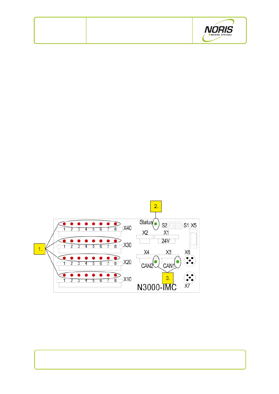
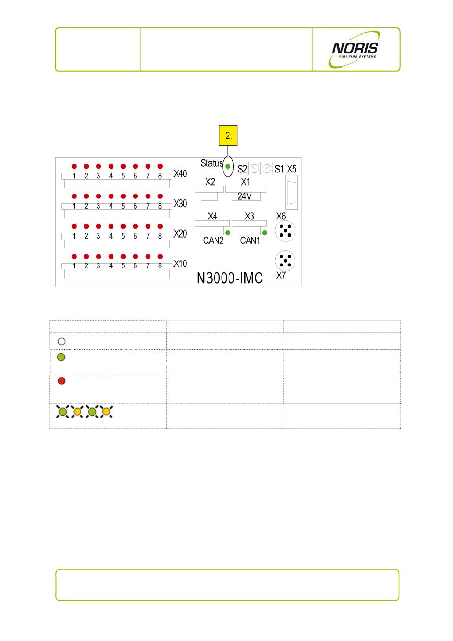
The illustration below shows the arrangement of LEDs on the I/O boxes.
Fig. 3: N3000-IMC - overview of status LEDs
Explanations for the previous illustration:
1. Thirty-two channel status LEDs (one per channel) (see Section 3.4.1)
2. One system status LED (see Section 3.4.2)
3. Two CANbus LEDs (only master box N3000-IMC, see Section 3 .4.3)
The status LED indicator codes and their significance will be explained in the subsections below.
12 / 20
NORIS Marine Systems GmbH & Co. KG, Muggenhofer Strasse 95, D - 90429 Nuremberg
Phone: +49 911 32 01-0, Fax: +49 911 32 01-150, info@noris-automation.com, www.noris-automation.com
NMS-KD-0017-en
Version 01.03
19/11/2009 - DHI
N3000-IMC and -ISC
User Manual
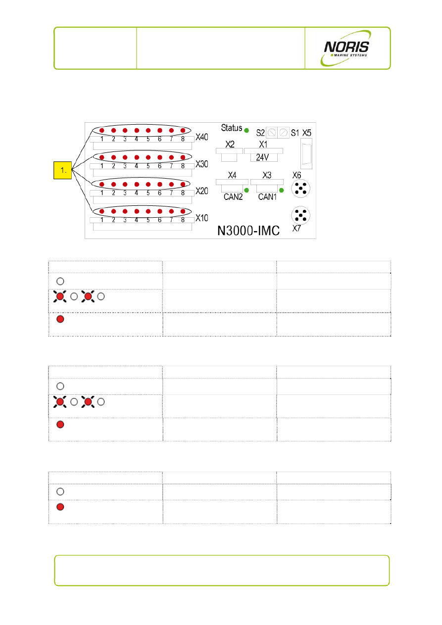
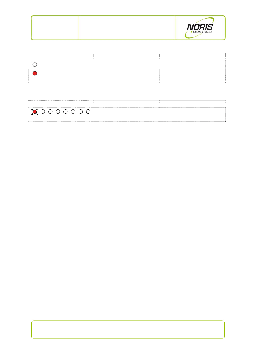
3.4.1 Channel status LEDs indicator code
Fig. 4: N3000-IMC - channel status LEDs
Indicator code for sensor alarm (see previous Figure, No. 1)
LED indicator code
Explanation
Status / significance
LED off
no alarm
rd* rd*
flashing alternately red/off
sensor alarm (not acknowledged)
rd
steady red
sensor alarm (acknowledged)
*rd=red
Indicator code for sensor fault (see previous Figure, No. 1)
LED indicator code
Explanation
Status / significance
LED off
no sensor fault
rd* rd*
flashing red/off
sensor fault (not acknowledged)
rd
steady red
sensor fault (acknowledged)
*rd=red
Indicator code for blocking channels (see previous Figure, No. 1)
LED indicator code
Explanation
Status / significance
LED off
blocking inactive
rd*
steady red
blocking active
*rd=red
13 / 20
NORIS Marine Systems GmbH & Co. KG, Muggenhofer Strasse 95, D - 90429 Nuremberg
Phone: +49 911 32 01-0, Fax: +49 911 32 01-150, info@noris-automation.com, www.noris-automation.com
NMS-KD-0017-en
Version 01.03
19/11/2009 - DHI
N3000-IMC and -ISC
User Manual
Indicator code for status/actuator channels (see previous Figure, No. 1)
LED indicator code
Explanation
Status / significance
LED off
off / low / inactive / actuator off
rd*
steady red
on / high / active / actuator on
*rd=red
Indicator code for faded channels (see previous Figure, No. 1)
LED indicator code
Explanation
Status / significance
rd*
t on/off = 1/8
channel faded out
*rd=red
14 / 20
NORIS Marine Systems GmbH & Co. KG, Muggenhofer Strasse 95, D - 90429 Nuremberg
Phone: +49 911 32 01-0, Fax: +49 911 32 01-150, info@noris-automation.com, www.noris-automation.com
NMS-KD-0017-en
Version 01.03
19/11/2009 - DHI
N3000-IMC and -ISC
User Manual
3.4.2 System status LED indicator code
Fig. 5: N3000-IMC - system status LED
Indicator code for system status LED (see previous Figure, No. 2)
LED indicator code
Explanation
Status / significance
LED off
I/O box inactive/off
gn*
steady green
I/O box ok
rd*
steady red
internal system fault
or
boot mode (about 10 ... 20 s)
gn* ye* gn* ye*
flashing alternately red/yellow
earth fault of sensor / sensor line
* rd= red; gn=green; ye=yellow
15 / 20
NORIS Marine Systems GmbH & Co. KG, Muggenhofer Strasse 95, D - 90429 Nuremberg
Phone: +49 911 32 01-0, Fax: +49 911 32 01-150, info@noris-automation.com, www.noris-automation.com
NMS-KD-0017-en
Version 01.03
19/11/2009 - DHI
N3000-IMC and -ISC
User Manual
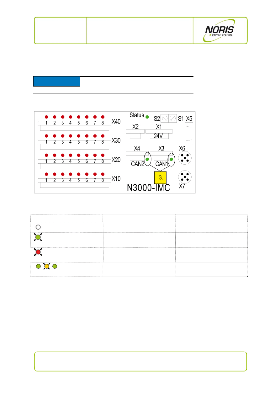
3.4.3 CANbus LEDs indicator code
Fig. 6: N3000-IMC - CANbus status LEDs
Indicator code for CANbus LEDs (see previous Figure, No. 3)
LED indicator code
Explanation
Status / significance
LED off
CANbus not active
gn*
pulsing green LED
transmitting over the CANbus
rd*
pulsing red LED
receiving over the CANbus
gn* ye* gn*
LED occasionally flashes yellow
immediate confirmation of received
data
* rd= red; gn=green; ye=yellow
NOTICE
Only the master box N3000-IMC has CANbus
connections with CANbus status LEDs
.
16 / 20
NORIS Marine Systems GmbH & Co. KG, Muggenhofer Strasse 95, D - 90429 Nuremberg
Phone: +49 911 32 01-0, Fax: +49 911 32 01-150, info@noris-automation.com, www.noris-automation.com
NMS-KD-0017-en
Version 01.03
19/11/2009 - DHI
N3000-IMC and -ISC
User Manual
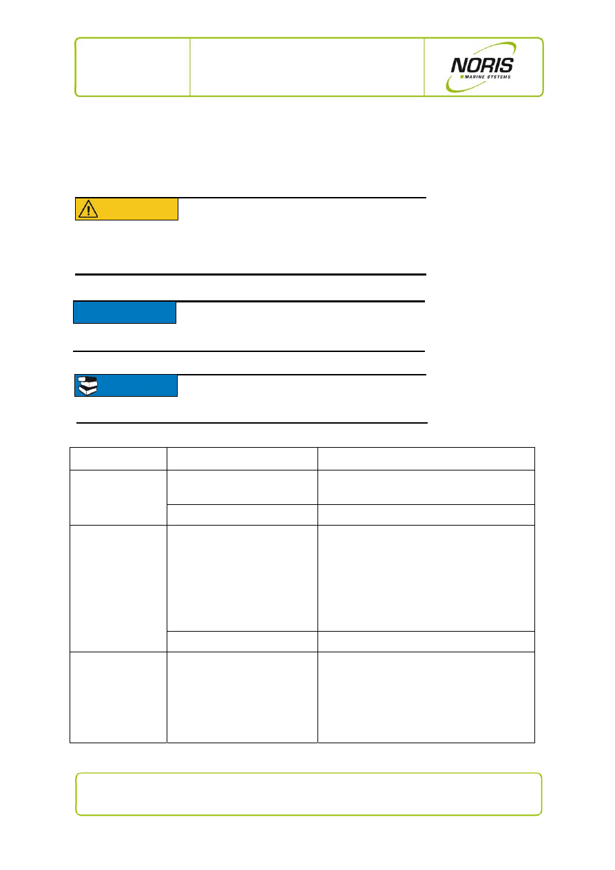
3.5 Fault reports and fault clearing
This section describes the possible fault reports, their causes and possible means of clearing faults. If
you are unable to resolve the system's fault please contact service personnel.
Fault indication
Possible fault
Possible
remedy
System status LED
off
no supply voltage
Check terminal X1 (power supply).
device
fault
Call service personnel or replace device
System status LED
red
iBus connection disturbance
Tip about iBus problems:
In SYSTEM INTERNALS of the
N3000-DSP message "iBus
Connection Box 1, …"
1. Check terminal X6, X7 (iBus connection) and
the iBus cable.
2.
Remove power supply from terminal X1, then
connect it again re-initialisation. Wait for
30 s if iBus remains defective go to next
step.
3.
Call service staff or replace device.
internal system fault
Call service personnel or replace device
System status LED
alternately
green/yellow
earth fault to the I/O box
Tip about earth fault:
In the SYSTEM INTERNALS
display message "Insulation Box
1, 2 …"
Check sensor and sensor lead.
CAUTION
Disturbances in the N3000 system can effect
the entire system. To avoid damaging
equipment, always take appropriate initial
action (e.g. switching off the motor, etc.) before
beginning with troubleshooting.
NOTICE
Some malfunctions can be more quickly and specifically
located with the aid of the N3000-DSP display. The
table below will point this out.
READ
For more information about troubleshooting, please
read the N3000 Service Manual NMS-KD-0015.
17 / 20
NORIS Marine Systems GmbH & Co. KG, Muggenhofer Strasse 95, D - 90429 Nuremberg
Phone: +49 911 32 01-0, Fax: +49 911 32 01-150, info@noris-automation.com, www.noris-automation.com
NMS-KD-0017-en
Version 01.03
19/11/2009 - DHI
N3000-IMC and -ISC
User Manual
Fault indication
Possible fault
Possible
remedy
Sensor input LED
steady red but limit
value is not overrun
sensor fault, wire-break or short
circuit
Check sensor and sensor lead.
Many alarms (2 or
more) simultaneously
indicate a sensor
fault (SF)
Suspect: only one channel may
have a real sensor fault (SF).
The defective channel may serve
as a source or reference channel
(source channel, cold junction
channel).
Example: The channel for cold
junction temperature has SF all
thermal elements dependent on
this channel will also show SF.
Check sensor and sensor lead.
If an N3000-DSP display unit is available:
1. Call up the CHANNEL DETAILS for the
channel XXXX with a SF.
2. Is there a "source channel" or "cold junction
channel" message present?
No, no message: check this channel
(sensor, wire break, etc.)
Yes, message present: check the channel
indicated by the message as a "source
channel" or "cold junction channel"
(sensor, wire break etc.)

18 / 20
NORIS Marine Systems GmbH & Co. KG, Muggenhofer Strasse 95, D - 90429 Nuremberg
Phone: +49 911 32 01-0, Fax: +49 911 32 01-150, info@noris-automation.com, www.noris-automation.com
NMS-KD-0017-en
Version 01.03
19/11/2009 - DHI
N3000-IMC and -ISC
User Manual
4. Technical Data
Operating voltage
18 … 32 V DC, U
rated
= 24 V DC
Power consumption
< 25W (N3000-IMx), < 20W (N3000-ISx)
Operating temperature range
acc. IEC60068-2-2 and
IEC60068-2-1Ad
25°C … +70°C
Storage temperature range
acc. IEC60068-2
-40°C … +85°C
Relative air humidity
acc. IEC60068-2-30 Db
≤ 96% @ 55°C
Vibration resistance
acc. IEC60068-6 Fc
±1,6mm @ 2…25 Hz, 4g @ 25…100Hz
Shock resistance (impact)
acc. IEC60068
ESD
acc. IEC61000-4-2
8kV via air, 6kV via contact
Electromagnetic field
acc. IEC61000-4-3
10 V/mf = 80MHz … 2000MHz 80% AM @ 1kHz
10 V/m f = 900 ±5 MHz 50% AM @ 200Hz
10 V/m f = 1800 ±5 MHz 50% AM @ 200Hz
Burst acc.
IEC61000-4-4
± 2 kV operating voltage
± 1 kV sensorlines
Surge acc.
IEC61000-4-5
sym. ± 0.5 kV (Ri=2Ω)
asym. ± 1 kV (Ri=12Ω)
Conducted HF-interference
acc. IEC61000-4-6
10 V
rms
f = 0,01 …100MHz 80% AM @ 1kHz
Conducted LF-interference
acc. IEC60553
10 V
rms
f = 0,05 …10kHz
Interference field strength
acc. CISPR 16-1- EMC1
Connections
Plug connectors
System Phoenix Mini-Combicon -Ø wires ≤ 2.5mm²
Power supply
spring balancer terminal type: FKCS 2.5/4-STF-5.08
or terminal screw type: FRONT-MSTB 2.5/4-STF-5.08
iBus
Screw connector M12-5
I/O-channels
spring balancer terminal type: FKCS 2.5/16-STF-5.08
or terminal screw type: FRONT-MSTB
2.5/16-STF-5.08
CANbus
spring balancer terminal type: TFKC 2,5/3-STF-5.08
or terminal screw type: FRONT-MSTB
2.5/16-STF-5.08
Serial interface
RS232 / RS422 / RS485
Sub-D 9 socket
Protection class
to DIN EN60529
Front (panel, rack) IP65 built into mounting plate
All other sides IP30
Connections
IP00
Orientation
preferably vertical up

19 / 20
NORIS Marine Systems GmbH & Co. KG, Muggenhofer Strasse 95, D - 90429 Nuremberg
Phone: +49 911 32 01-0, Fax: +49 911 32 01-150, info@noris-automation.com, www.noris-automation.com
NMS-KD-0017-en
Version 01.03
19/11/2009 - DHI
N3000-IMC and -ISC
User Manual
Box type
Panel-mounting
Cabinet-mounting
Housing material Front:
Polyester film on chromated
aluminium plate
chromated aluminium
Body:
chromated aluminium chromated
aluminium
Mounting in
console
with
4 studs M5 x 16mm
back-plate with
4 oblong drilled holes 6.5 x 8mm
Dimensions
Front plate
length 250mm
width
140mm
depth 4mm
back-plate length
210mm
width
140mm
depth 4mm
Body L210mm, B110mm, T approx. 115mm without cable space
Weight approx.
1.6kg
Applied standards
IEC61000-6-2, IEC61000-6-4

20 / 20
NORIS Marine Systems GmbH & Co. KG, Muggenhofer Strasse 95, D - 90429 Nuremberg
Phone: +49 911 32 01-0, Fax: +49 911 32 01-150, info@noris-automation.com, www.noris-automation.com
NMS-KD-0017-en
Version 01.03
19/11/2009 - DHI
N3000-IMC and -ISC
User Manual
Table of figures
Fig. 1: N3000-IMC connections side ....................................................................................................... 6
Fig. 2: N3000-ISC connections side ........................................................................................................ 8
Fig. 3: N3000-IMC - overview of status LEDs ....................................................................................... 11
Fig. 4: N3000-IMC - channel status LEDs ............................................................................................ 12
Fig. 5: N3000-IMC - system status LED ................................................................................................ 14
Fig. 6: N3000-IMC - CANbus status LEDs ............................................................................................ 15
Wyszukiwarka
Podobne podstrony:
C 12232 EN V01 formateur
8 Anatomia mięśnii kg,kd komentarzdla sudentów 17 03 07
KD 2006 154 01 03 Instrukcja i Schemat
C 12232 EN V01 stagiaire
BeBalanced SkiTraining EN low 03
C 12232 EN V01 formateur
C 12232 EN V01 formateur
Instrukcja obs ugi do radioodtwarzacza samochodowego JVC KD R711 EN (videotesty pl)
8 Anatomia mięśnii kg,kd komentarzdla sudentów 17 03 07
GE MT96 Series Final Manual EN v01
RTXAGENDA EN v01 08
i9 user manual (en)
69 Han Solo Adventures 03 Han Solo and the Lost Legacy
Robert Don Hughes Pelman 03 The Power and the Prophet
JetFlash Online Recovery User Manual EN
więcej podobnych podstron