
L
ike water, power, and compressed
air, vacuum is a standard utility
in many chemical process plants.
Commonly used, for instance, to
remove gases or vapors that other-
wise would interfere with a reaction,
vacuum enhances reaction efficiency
and yield and the recovery of essen-
tial compounds.
Under vacuum, the boiling point of
liquids is reduced, which is useful for
the processing of temperature-sensi-
tive materials and the separation of
liquids. Heat transfer through liquids
is more efficient without the presence
of air bubbles, while solid end-prod-
ucts produced under vacuum from a
liquid phase are more homogeneous,
and are virtually free of voids caused
by unwanted gas bubbles. Also, ag-
gressive compounds that must be con-
tained can be better and more safely
handled and transferred using vac-
uum. In particular, vacuum is used to:
• Remove air and its constituents,
such as oxygen and water vapor,
which, if they are combined with a
process constituent, could alter a
chemical reaction
• Remove excess reactants or un-
wanted byproducts that can com-
promise efficiency and yield
• Reduce the boiling point for distilla-
tion of mixtures
• Dry solute material by removing the
solvent
• Create a pressure differential for
initiating transport of material
from one section to another or
through filtration media
Vacuum is generated by vacuum
pumps. The spectrum of vacuum
pumps is large, and it can include
multiple stages of pumps in combina-
tion to provide systems that either
operate at lower pressures or accom-
modate larger pumping capacities.
The main building block for any
vacuum system is a primary-stage or
atmospheric-stage vacuum pump,
which exhausts directly to the atmos-
phere. Primary pumping devices are
categorized based on the method by
which they pump gas:
• Mechanically trap gas and transport
it from suction to discharge. Positive-
displacement pumps are the best ex-
ample of this method of operation
• Transfer momentum through a mo-
tive fluid. Steam or vapor ejectors
and air ejectors employ this method
of operation
• Capture gas on extended surfaces
using porous media at cryogenic
temperatures. Sorption pumps
work on this principle
The first two categories are most
widely used the chemical process in-
dustries (CPI). Steam ejectors, long
considered the workhorses of vacuum
processing, are easy to use and oper-
ate (CE, March 1999, pp. 96–100).
However, concerns about energy con-
sumption and environmental pollu-
tion associated with them have slowed
the demand for these types of pumps.
Preferable for a growing number of
applications are hybrid systems that
incorporate a steam-ejector stage
backed by a mechanical pump stage —
for instance, a steam ejector stage/in-
terstage condenser/liquid-ring pump
stage, all in series — or systems con-
sisting entirely of mechanical pumps.
PUMP MECHANICS
AND OPERATION
A pump used in CPI applications
should have the capability to:
• Process various solvent vapors with-
out harm
• Avoid pollution of the process and
the environment
• Keep waste generation to a mini-
mum
• Resist corrosion
• Handle flammable gases or vapors
• Ingest some liquid without harm
Oil-sealed pumps
Of the primary positive-displacement
pumps, oil-sealed rotary piston and
vane pumps are most similar in range
in terms of pumping capacity and ulti-
mate pressures (vacuum levels). Both
rely on oil for three main functions:
• Sealing the internal clearances be-
tween rotary components and hous-
ing to reduce gas slippage
• Transferring the heat of gas com-
pression
• Lubricating the rotary internals
This dependency upon the oil for in-
ternal lubrication is a limiting factor
in the use of these type pumps in the
CPI. The integrity of the oil must be
maintained to avoid internal damage
that could cause contaminant buildup.
Particulates in the oil must be filtered
out ahead of the pump, and water or
solvent vapors must be either knocked
out ahead of the pump by precon-
densers, or prevented from condens-
ing within the pump by gas ballasting
(air stripping) or oil distillation.
Rotary piston. The rotary piston
pump is extremely robust and stands
up well to adverse process conditions.
Typically constructed of cast iron, this
pump has four basic rotary compo-
nents: a shaft, eccentric cam, piston,
and slide pin. The cam is eccentrically
Feature Report
4 4
CHEMICAL ENGINEERING WWW.CHE.COM OCTOBER 2004
Mechanical Pumps for
Vacuum Processing
Liquid ring and dry pumps are best-suited for
applications in the chemical process industries
Phil Vibert
Tuthill Vacuum & Blower Systems
mounted to the shaft and the piston is
concentric to the cam. This arrange-
ment allows the piston to ride on the
cam and rotate around the periphery
of the pump housing (cylinder), form-
ing a void between the piston and
housing that alternates from maxi-
mum to zero at top dead center.
The positioning of the eccentric cam
on the shaft results in an imbalance. To
compensate, two or more such stages of
rotary components are placed on the
shaft, with each 180 deg out of phase
with the stage next to it. These stages
are normally arranged in parallel for
single-stage pumps or in series for com-
pound pumps (Figure 1). Single-stage
rotary piston pumps can provide pres-
sures down to 0.005 mm Hg abs and ca-
pacities to 850 cfm; compound pumps,
0.0002 mm Hg abs and 200 cfm.
The geometric positioning of the pis-
ton-cam-shaft assembly prevents the
piston from touching the cylinder
wall, allowing a constant clearance to
be maintained at all times. Oil is used
to seal this gap between the piston
and cylinder, provide lubrication and
transfer heat throughout the rest of
the pump.
Rotary vane. The advantage of the
rotary vane pump is its inherently
well-balanced design. Its disadvan-
tage is the sensitivity of its vanes to
sticking or breaking from deteriora-
tion of the lubricant or ingestion of
process liquid.
This pump employs a rotor concen-
tric with the shaft, with slots for ac-
ceptance of two or more vanes, provid-
ing the inherently balanced design.
The rotor-shaft assemblage is
mounted eccentrically in the stator
cylinder to provide the necessary cres-
cent-shaped volume for expansion and
compression, with the critical dimen-
sion being the rotor-to-stator clear-
ance between the suction and dis-
charge porting at top dead center. The
clearance must be kept as small as
possible to reduce gas slippage where
the pressure differential is greatest.
The use of multiple vanes in the
rotor allows the pumping volume to be
swept the same number of times in one
shaft rotation, providing a compact de-
sign. The vanes can be spring-loaded,
or more commonly, can rely on cen-
trifugal force to make contact with the
cylinder and seal off the gas pocket.
Contact pressure between the vane
and housing is high, resulting in signif-
icant frictional effects that increase in-
ternal localized temperatures, even in
the presence of oil, which provides lu-
brication, sealing and cooling.
Various designs of vane pumps are
available, typically with capacities to
1,000 cfm. Some are capable only of
ultimate pressures from 15 to 0.5 mm
Hg absolute for rough industrial ap-
plications, while others are capable of
ultimate pressures from 0.1 to 0.0002
mm Hg abs for use in applications
with higher vacuum requirements.
A vane pump that uses a once-
through oiling system is an alternative
to those that recirculate oil. In the
once-through approach, oil flow is me-
tered out in amounts just sufficient to
seal and lubricate the vanes to the
housing. Instead of being recycled, the
oil is collected for disposal. The advan-
tage of this design is that any contam-
ination of the oil by the process vapor
is passed out of the pump and not al-
lowed to build up and cause additional
problems. This design also avoids any
increases in the operating pressure
due to the vapor pressure of residual
process vapors. The drawback is the
need for waste oil disposal, which is an
environmental and cost issue.
Liquid ring pumps
Liquid ring pumps employ one or two
multiblade impellers concentrically
mounted to the drive shaft. The im-
peller shaft assembly is eccentrically
mounted in the pump housing, in such
a way that at top dead center the clear-
ance between impeller blade tip and
housing is at a minimum, and at bot-
tom dead center the clearance is at a
maximum, resulting in a relatively
CHEMICAL ENGINEERING WWW.CHE.COM OCTOBER 2004
4 5
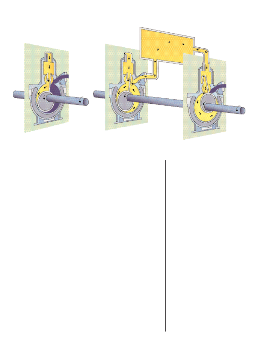
FIGURE 1a–b.
In a rotary piston pump, positioning of the eccentric cam on the shaft results in
an imbalance. To compensate, two or more such stages of rotary components are positioned on
the shaft 180 deg out of phase from each other. These stages are normally arranged in parallel
(common inlet and outlet) for single-stage pumps or in series for compound pumps (inlet and outlet in series)

large void (Figure 2).
The sealant liquid, typically
water (but see further discus-
sion below), is used to seal be-
tween the impeller blade tips
and housing. The sealant liq-
uid is thrown by the impeller
against the inside walls of the
pump housing, where it forms
a rotating ring of liquid.
At top dead center, the ring of
sealant liquid completely fills
the voids between the blades of
the impeller. Because of the ec-
centric position of the impeller
with respect to the housing as it
rotates around the ring of liq-
uid, the sealant is peeled away
from the spaces between the
blades, creating voids where
gas can enter and be trapped.
At bottom dead center, voids
between the impeller blades
and ring liquid are at a maxi-
mum, while the blade tips re-
main immersed in the liquid
ring for sealing. As the impeller
continues to rotate back up
from bottom dead center to top
dead center, the sealant begins
to refill the volume between the
blades, creating an essentially
isothermal compression of the
gas trapped within.
Inlet-outlet porting are posi-
tioned either in an endplate or a
port cone positioned at the axial end of
the impeller. In the endplate arrange-
ment, two ports for entering and exit-
ing of gas normally straddle an imagi-
nary line connecting top dead center to
bottom dead center, but the ports (nor-
mally triangular) can vary in shape
and exact location depending upon the
vendor. With this kind of arrangement,
the sealant liquid acts as a liquid pis-
ton, alternately creating expansion and
compression for the gas trapped in the
spaces between the impeller blades.
Because ring energy is derived from
the impeller rotational speed, the
minimum number of rotations per
minute (rpm) that a given liquid ring
pump can operate can be estimated.
Since pressure = force/area,
P = F/A =
r
V
w
2
R/A =
r
V
(2
p
(rpm)/60)
2
R/A =
r
V
p
2
(rpm)
2
R/(900A)
(1)
where
A = unit area in in.
2
G = gravitational acceleration of 32.16
ft/s
2
at sea level
r
= sealant liquid density in (lb/in.
3
)
D
p = gas differential pressure across
the pump for single-stage pumps and
the pressure differential for two-stage
pumps in (lb/in.
2
)
P = ring pressure due to the impeller
in (lb/in.
2
A)
V = hA is the volume of sealant in
(in.
3
)
h = impeller blade height or sealant
ring thickness in inches
R = effective impeller radius in ft
rpm = rotations per minute
Then, for a unit surface area, A,
where the ring is sealing against a
maximum differential pressure,
D
p,
for the gas being pumped across each
impeller stage, the minimum ring
pressure, P must be greater than
D
p
then
rpm
min
= [900G
D
p/(
r
V
p
2
R)]
1/2
(2)
As shown, ring pressure for sealing
is dependent on both the impeller rpm
and radius, as well as the density of
the sealant liquid.
Liquid ring pumps are available as
single-stage (one or two impellers in
parallel) or two-stage (two impellers
in series). Using 60°F sealant water,
single-stage pumps are capable of
achieving 100 mm Hg abs, while two-
stage or compound pumps can achieve
30 mm Hg abs. Pumping capacities up
to and over 20,000 cfm are available.
Liquid ring pumps are well de-
signed for the CPI. They do not re-
quire internal lubrication of the im-
pellers, which do not contact the
housing. The sealant liquid, used for
both sealing and cooling, can be any
liquid that is compatible with the
Feature Report
4 6
CHEMICAL ENGINEERING WWW.CHE.COM OCTOBER 2004
LIQUID RING VERSUS DRY PUMP SYSTEMS
COMPARISON OF OPERATING AND MAINTENANCE COSTS
Liquid Ring Pump
Dry Pump
two-stage variable
pitch
System
stainless steel
rotary screw
Capacity (acfm)
100
400
100
400
Steam usage (lb/h)
0
0
0
0
Cost of steam ($/1,000 lb)
6
6
6
6
Annual cost of steam ($)
0
0
0
0
Motor hp
7.5
40
5
20
Total bhp
7
33
4.4
15
Power consumption kWh/yr
46,418
218,827
29,177
99,467
Unit cost of power ($/kWh)
0.06
0.06
0.06
0.06cot
Annual cost of power ($/yr)
2,785.07
13,129.60
1,750.61
5,968
Cooling water usage (gal/min)
9
27
1
5
Cost of cooling water ($/1,000 gal)
0.5
0.5
0.5
0.5
Annual cooling water cost ($/yr)
2,160
6,480
240
1,200
Wastewater to be treated (gal/min)
0.25
0.5
0
0
Wastewater treatment cost ($/1,000 gal)
2.5
2.5
2.5
2.5
Annual cost of wastewater treatment ($/yr)
300
600
0
0
Total quantity of oil (gal)
0
0
0.3
0.3
Cost of oil ($/55-gal drum)
400
400
400
400
Changeout intervals (h)
1,000
1,000
1,000
1,000
Annual cost of oil ($/yr)
0
0
17.45
17.45
Cost of oil disposal ($/55-gal drum)
100
100
100
100
Cost of oil waste disposal ($/yr)
0
0
4.36
4.36
Cost for oil filter element ($)
0
0
0
0
Recommended filter changeout interval (h) 1,000
1,000
1,000
1,000
Annual cost of exhaust filters
0
0
0
0
Annual cost of pump overhaul
340
780
2,550
4,930
Annual total cost per pump ($/yr)
5,585.07
20,99.60
4,562.43
12,119.82
Annual savings per system ($)
None
None
1,022.64
8869.78
Capital costs ($)
14,800
40,000
23,000
48,000
Higher capacity (%)
None
None
None
None
First-year total cost/cfm ($)
203.85
152.47
275.62
150.30
Second-year total cost/cfm ($)
55.85
52.47
45.62
30.30
Higher second-year cost/cfm (%)
22.4
73.2
0
0
Payback time (yr)
–
–
8.0
0.9
process and falls within the following
range of physical properties:
• Specific gravity 0.5< S.G 1.5
• Specific heat 0.35< S.H. 1, relative
to that of water
• Viscosity 1 cP
n
32 cp
• Vapor pressure V
p
sealant at operat-
ing temperature V
p
water at 60°F
Low-viscosity oils, glycols, and many
process solvents, such as toluene, xy-
lene, methanol, ethanol, propanol, bu-
tanol and ethylbenzene, can be used as
sealants. These sealants can be recircu-
lated in a full recovery system that in-
cludes a gas-liquid separator tank and
a heat exchanger for cooling. Even
higher-vapor-pressure liquids can be
used if a low-temperature coolant is
used in the heat exchanger to reduce
the sealant temperature. This recovery
system allows process materials to be
collected in the pump and either re-
turned to the process or collected for
disposal, while minimizing contamina-
tion of other liquids or the environment.
Liquid ring pumps offer many ad-
vantages, among them:
• Simplicity of operation (such a pump
is essentially a pinwheel on bear-
ings) with minimal moving parts,
and no lubricating liquid in the vac-
uum chamber to be contaminated
• Large choice of sealant liquids
• Accommodation of both condensable
vapors and noncondensables, while
operating as both a vacuum pump
and condenser
• Ability to handle small liquid
streams along with the gas flows
from the process or precondensers
• Wide choice of materials of con-
struction, with all-ferrous, all-
bronze, and all-stainless steel being
the most common
The major disadvantage of the liquid
ring pump is its power consumption,
compared with that for other types of
mechanical pumps. While frictional
power due to seals, bearings, and drag
on rotational elements represents
30–40% of total peak power consump-
tion in rotary vane and piston pumps,
it accounts for 50–75% of total power
consumed in liquid ring pumps. The
power consumed by liquid ring pumps
in pumping gas can be determined
from the isothermal compression of
gas across each stage:
GHP = (144/33,000)P
1
Dln(P
2
/P
1
)
(3)
where
GHP = work done on gas (hP)
P
1
= inlet pressure (psia)
D = displacement (cfm)
P
2
= discharge pressure (psia)
The low-pressure performance of
single-stage liquid ring pumps is nor-
mally limited by gas slippage from
discharge back to suction, while in
two-stage pumps, a combination of
slippage, sealant vapor pressure and
gas solubility of the sealant limits the
ultimate pressure. When a low-viscos-
ity oil is used as sealant in a two-stage
liquid ring pump, ultimate pressures
of 2–5 mm Hg abs are routinely
achieved. Here the limitation is not
the vapor pressure of the sealant,
which is likely to be less than 10
–4
mm
Hg abs at 100°F, but the air solubility
in the oil and slippage between stages.
All liquid ring pumps must cope
with cavitation when running at low
inlet pressures. Cavitation is the
rapid formation and collapse of vapor
bubbles within the sealant liquid,
which can remove minute amounts of
metal from surfaces. If cavitation is
allowed to continue over long periods
of time, serious damage can be done to
the liquid ring pump. Tiny voids
within the sealing liquid can be cre-
ated by the pump’s impeller. When
the ring is exposed to the suction port
at low pressures, some of the sealant
liquid can vaporize to fill the void with
a small vapor bubble, which travels
around from suction to discharge,
causing vapor bubbles to collapse.
When the bubbles collapse on a metal
surface, the shock force can tear small
amounts of metal away.
The amount of cavitation can be af-
fected by the sealant liquid, sealant
temperature, impeller rpm, blade
angle, and inlet pressure. For a given
pump and sealant liquid, cavitation
can normally be suppressed by bleed-
ing air into the pump inlet to raise its
total pressure above the vapor pres-
sure of the sealant at operating tem-
peratures.
Dry pumps
Dry vacuum pumps do not use any liq-
uid in the pumping chamber. In the
1980s, semiconductor fabricators real-
ized the potential of dry pumps as an
CHEMICAL ENGINEERING WWW.CHE.COM OCTOBER 2004
4 7
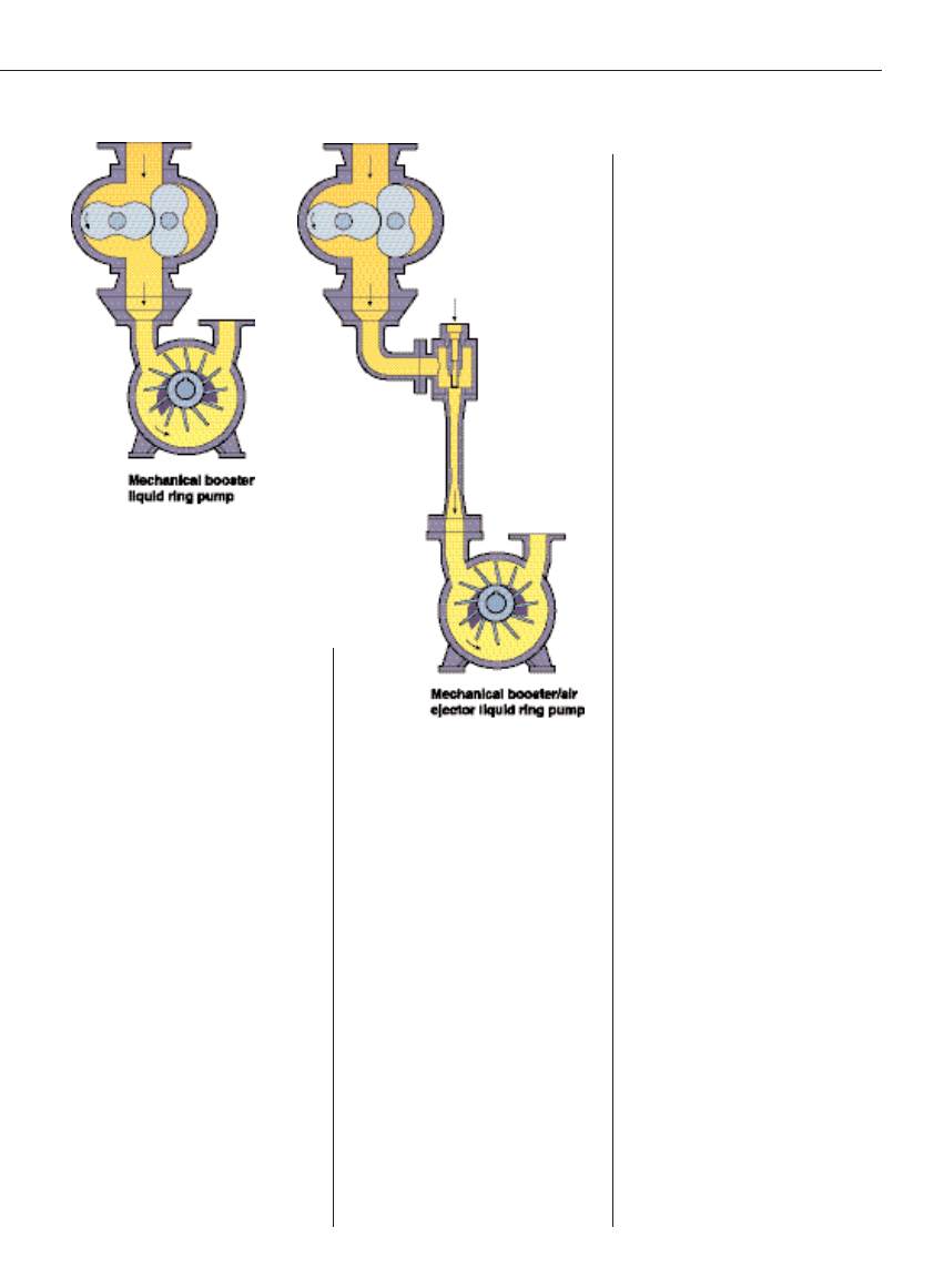
FIGURE 2 a–b.
Typically used as a mechanical
booster, the rotary lobe pump is used in series with
another vacuum pump — in this case, a liquid ring
— that functions as the primary pump. Another
option is a multistage vacuum pump system that
includes an air ejector
alternative to the oil-sealed pumps
that were used to provide pressures of
0.01–1 mm Hg abs for chemical vapor
deposition and etching of wafers.
In semiconductor manufacture, oil-
sealed pumps require lubrication with
inert, fluorine-based fluids for protec-
tion from the corrosive gases and
harsh conditions of the fabrication op-
eration. In addition to the expense of
the lubricants are the costs of associ-
ated materials and maintenance.
With a dry vacuum pump, not only
are lubricants eliminated; buildup of
process gases within the pump and
waste disposal are also reduced. But
eliminating a liquid within the pump-
ing chamber also eliminates a method
of sealing between the pump clear-
ances, a heat-transfer material for
temperature control, as well as a flush
medium for cleaning the pump inter-
nals of process material. So, the chal-
lenges of providing dry-runing pumps
were large.
Early dry pumps consisted of sev-
eral pumping stages in series, with
either rotary lobes or hook-and-claw
internals that did not make any con-
tact with the housing and used tim-
ing gears to synchronize the two par-
allel rotor shafts. While this
configuration eliminated the need for
a lubricant within the pumping
chamber, the lack of a seal medium
meant that the internal clearances
had to be kept tight to reduce gas
slippage. The tight clearances made
some of the dry pumps sensitive to
buildup of process particulate. The
evolution of these designs saw the in-
troduction of various inert gas purges
to flush process material through the
pump or act as a diluent for flamma-
ble or corrosive gases, or help to con-
trol internal temperatures.
The eventual success of dry vacuum
pumps in the semiconductor industry
has inspired pumpmakers to intro-
duce these pumps into other segments
of the CPI, where the benefits of a dry
pumping chamber can lower operat-
ing costs and justify the cost of the
generally higher-priced pump.
For CPI use, considerations for han-
dling liquid slugs or higher vapor
loads from the process need to be
weighed. Various types of dry pumps
are currently available, including
scroll, diaphragm, rotary
vane, rotary lobe, hook-
and-claw, and rotary
screw. However, the ro-
tary lobe, hook-and-
claw, and rotary screw
pumps are the ones that
dominate the CPI sector,
particularly in larger-size
pump applications.
Scroll pump. The scroll pump uses a
rotating plate shaped into a spiral (in-
volute curve), which moves within a
second stationary plate, shaped as a
similar spiral. This rotating motion of
one spiral within another creates cres-
cent-shaped trapped volumes, within
which the gas moves from the outside
of the spiral to the center, where the
gas is exhausted through a valve. Mul-
tiple stages can be used to provide
lower pressures, down to 0.01 mm Hg
abs, with pumping capacities limited
to less than 50 cfm. Because its tortu-
ous spiral gas path can act as a trap for
particulates within the pump, this
type of pump is limited to clean gas ap-
plications.
Diaphragm pump. The diaphragm
pump uses a rotating eccentric piston-
plunger to move an elastomeric di-
aphragm back and forth within a
small cavity, resulting in a rapid re-
duction and expansion of volume to
provide pumping action for gases.
Chemical-resistant diaphragms are
available in polytetrafluoroethylene
(PTFE), but the relatively small size
of this type of pump precludes its use
in production-scale operations and
relegates it to laboratory applications.
Ultimate pressures vary, with the
lowest being about 1 torr.
Dry rotary vane. While the dry rotary
vane pump is available with self-lubri-
cating carbon vanes, the increased gas
slippage compared to that of the oil-lu-
bricated vane pump limits the ultimate
pressure of the dry vane to about 75
mm Hg abs. These pumps offer capaci-
ties up to approximately 400 cfm. As
with most dry pumps, which lack a liq-
uid heat-transfer medium in the pump-
ing chamber, it operates at elevated in-
ternal temperatures. Air cooling is
used. Due to this pump’s sensitivity to
particulates, inlet filtration is normally
recommended.
Rotary lobe. In use for more than 50
years, the rotary lobe pump is typi-
cally used as a mechanical booster
(Figure 2). Traditionally it has been
used in series with an oil-sealed pis-
ton or vane pump to amplify or boost
pumping capacity at low pressures, or
to extend low-pressure capability.
Today, it continues to be used in this
capacity, as well as in combination
with other types of dry pumps that
function as the primary or atmos-
pheric-stage pump.
The rotary lobe pump consists of two
symmetrical two-lobe (figure-eight) ro-
tors, each mounted on a separate shaft
in parallel, which rotate in opposite di-
rection to each other at high rotational
speeds without making any contact or
using any sealing liquid. This pump
uses timing gears to synchronize the
rotation of the lobes to provide constant
clearance between the two.
Internal clearances are kept to a
minimum — as tight as 0.004 in. — to
reduce the back slippage of gas and
still allow for thermal expansion of the
rotors. No internal compression of gas
occurs. The booster traps a pocket of
gas and transports it from low pressure
to high pressure. It is the discharge
pressure conditions at the booster pro-
duced by its backing pump that causes
the pressure ratio.
Typically, the rotary two-lobe is not
an effective pumping device for pres-
sures greater than 100 torr, due to its
increased power consumption. A pres-
sure switch is often used to energize
the blower only at lower pressures, or a
bypass circuit with valve, either inter-
nal or external, is used to limit the
pressure differential between suction
and discharge, limiting the power re-
quirements and exhaust gas tempera-
ture, while running at higher inlet
pressures (>100 torr). The booster does
not enhance the backing pump capac-
Feature Report
4 8
CHEMICAL ENGINEERING WWW.CHE.COM OCTOBER 2004
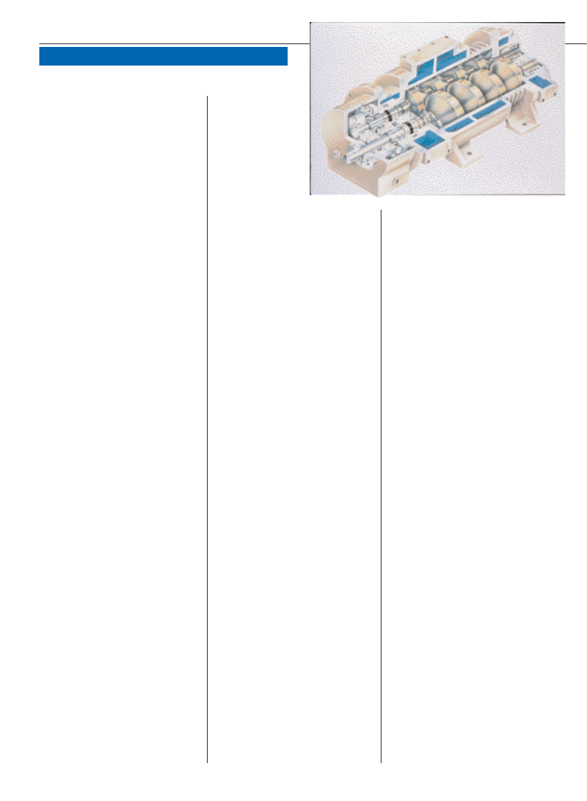
FIGURE 3.
The rotary screw pump
employs the pockets between
convolutions of the rotors as separate
stages in series to move gas in a flow path
that is simple, short and straight

ity until its bypass valve starts to close
at inlet pressures below 100 torr.
The greatest use of the rotary lobe
booster is as a separate pumping
stage, connected by piping to another
stage that discharges to the atmos-
phere. This separate atmospheric
stage can be provided by either an-
other type of dry pump, thus forming
an all-dry vacuum pumping system, or
by the more-conventional wet pumps.
Some dry pumps are manufactured
utilizing the rotary lobe design within
a single housing that can discharge to
atmosphere. One such design starts
out like a booster, with two counter-
rotating shafts in parallel. The design
diverges, however, with a rotary lobe
rotor mounted on each shaft as the
high vacuum stage, in series with two
or more different-design rotors all
mounted in series on the same drive
shaft. Each stage is separated by end-
plates with porting within the same
housing.
Another such design consists of two
counter-rotating shafts, each driving
three or more three-lobe rotors in se-
ries within the same housing. This de-
sign requires interstage cooling by re-
circulating a portion of the discharged
gas from one stage through a heat ex-
changer before injecting it back into a
point midway between suction and dis-
charge. The three-lobe design rotor
makes this possible without excessive
slippage. The problem with this design
is the tortuous gas path through a
complicated cooling circuit, where
process materials can accumulate or
precipitate out.
Some modifications to this design
have included replacing the external
interstage gas coolers with an internal
cooling-jacket design. This configura-
tion allows a portion of the discharged
gas to be passed through a peripheral
passage that is sandwiched between
the pumping chamber and cooling
jacket. This design allows the gas to be
cooled before being injected back into
the pumping chamber and reduces the
external complications of accessories,
however, it still leaves a tortuous path
for the gas where process material can
accumulate.
A complete rotary-lobe dry pump
that can operates from atmosphere to
less than 0.1 torr is possible if multi-
staging is used to reduce the differen-
tial pressure across each stage and its
corresponding gas slip.
Hook and claw. The hook-and-claw
pump makes use of the Northey rotor
design developed in the 1930s and
first used on compressors. This geo-
metrical shape allows for a greater
compression ratio to be taken across
the rotors at higher pressures. Two
claw rotors rotate in opposite direc-
tions of rotation without touching,
using timing gears to synchronize the
rotation; two complete rotations are
required to pass through the inlet,
compression, and discharge cycle. The
gas enters through an inlet port after
it has been uncovered and fills the
void space between the rotors and
pump housing. On the next rotation,
that same trapped sample of gas is
compressed and discharged as the dis-
charge port opens.
Hook-and-claw rotors perform two
functions: one is to trap, transport and
compress gas through the pumps, and
the other is to automatically open and
close the suction and discharge ports
like a valve by covering or exposing
the porting to the gas stream at the
appropriate times.
A minimum of three stages in series
is required to achieve ultimate pres-
sures comparable to those of an oil-
sealed mechanical pump. Some de-
signs use a mixture of hook-and-claw
rotor stages in series with rotary lobe
stages, while others use soley hook-
and-claw stages.
Gas purges are used to avoid partic-
ulate buildup. Discharge gas tempera-
ture is controlled by controlling the
flow of cooling water.
Rotary screw. The rotary screw
pump makes use of two long helical
rotors in parallel, which rotate in op-
posite directions without touching
(Figure 3). Helical timing gears are
used to synchronize the rotation. Gas
flow moves axially along the screw
without any internal compression
from suction to discharge. Pockets of
gas are trapped within the convolu-
tions of the rotors and the casing, and
transported to the discharge. Com-
pression occurs at the discharge port,
where the trapped gas must be dis-
charged against atmospheric pres-
sure. Each convolution of the rotor
acts similarly to a stage in series with
the one behind it. A minimum of at
least three convoluted gas pockets in
the rotor are required to achieve ac-
ceptable vacuum levels. Mechanical
face seals or lip seals are used to sepa-
rate the pumping chamber from the
bearings and gears.
The first generation of rotary screw
pumps use rotors with a constant
pitch (number of convolutions per unit
length). The second generation of
screw rotors utilize a variable pitch
design, which essentially consists of
two individual short rotors, each with
a different pitch, connected in series.
The gas at the inlet is first trans-
ported by the lower pitch (fewer con-
volutions per unit length) portion of
the rotors and then by the higher
pitch portion, which results in inter-
nal compression of the trapped gas.
The work for gas compression (as
measured by the area under a PV dia-
gram) using a variable pitch rotor is
less than that for the same task ac-
complished with a constant pitch
rotor. Because less energy is required,
the motor size of the variable pitch
rotor is smaller and the discharge gas
temperature is lower. The third gener-
ation uses a continuous variable-pitch
design rotor where the trapped gas is
continuously compressed from inlet to
discharge for greater efficiency with
the lowest energy requirement and
lowest discharge gas temperature.
The rotary screw pump is unique in
that it uses a singe stage (no inter-
stage walls) rather than the multi-
stage design of the other dry pumps,
which are separated by endplates and
seals. Because of this design, its gas
flow path is simple, short and straight
without any volumes in which mater-
ial can accumulate. The symmetrical
helical design lends itself to a well-
balanced rotor capable of high rota-
tional speeds.
Various protective coatings such as
PTFE or PFA (a copolymer of tetraflu-
oroethylene and perfluoroalkoxy
resin), or composites of PTFE and
nickel, are available for wetted inter-
nals to provide corrosion resistance to
aggressive process streams. Even with
these coatings, it is advisable to avoid
condensing the process corrosives
within the pump through the use of
CHEMICAL ENGINEERING WWW.CHE.COM OCTOBER 2004
4 9
inert gas purges and elevated gas tem-
perature control. Pumps sizes range
from 50 to 1500 cfm with ultimate
pressures of 0.2 to < 0.01 torr.
Dry service in the CPI
Of this selection of dry pumps, three
types are recommended for general-
purpose use in the CPI: the rotary
lobe, hook-and-claw, and rotary screw
pumps. These three dry pumps share
the following features:
• Rugged rotor design. Whether ro-
tary lobe, hook-and-claw, or rotary
screw all of the rotors are con-
structed of sturdy cast iron, or duc-
tile iron construction without any
flimsy rotating components.
• Noncontact design. Timing gears
are oil lubricated in a sealed-off end
chamber to synchronize the rotors
for proper phasing and noncontact-
ing operation
• High rotational speed. Operation at
high speeds reduces the ratio of gas
slip to displacement, increases net
pumping capacity and reduces ulti-
mate pressure. To accomplish this,
rotors are well balanced
• Multiple staging. Multiple staging
provides inlet pressures below 1 mm
Hg absolute while discharging to at-
mosphere (Figure 4). Being a sepa-
rate stage, the rotary lobe booster is
connected to another separate stage
of dry pump that discharges to at-
mosphere. The rotary lobe and hook-
and-claw pumps use multiple stages
within one housing, with each stage
sealed off from the other with end-
plates, except for the porting that di-
rects the gas along a tortuous path.
The rotary screw uses the pockets
formed by the convolutions in the
helical rotors as separate stages to
transport gas along a straight path
before discharging
LIQUID RING VS DRY PUMPS
When all capabilities are considered,
liquid ring and dry pumps offer the
most advantages for the CPI. Both of
these type pumps have bearings
sealed off from the pumping chamber
and do not require any internal lubri-
cation because the rotors do not con-
tact the housing; therefore, any sol-
vent vapor that condenses within the
pump will not compromise lubrica-
Feature Report
5 0
CHEMICAL ENGINEERING WWW.CHE.COM OCTOBER 2004
adlinks.che.com/3647-26
tion. Both employ a coolant system
that prevents the coolant from con-
tacting the process and causing conta-
mination, and both use mechanical
shaft seals for containment.
Dry pumps are free of any liquid
within the pumping chamber, so that
any process carryover is not contami-
nated and can be returned to the
process. Also the lack of any sealing
liquid means that the dry pump poses
no danger to contaminating the
process on system upsets. Although
water is the most commonly used
sealant in liquid ring pumps, in many
applications, the process fluid can in-
stead serve as the sealant liquid, pro-
vided the vapor pressure is compatible
with the operating pressure.
In other situations, a compatible
sealant liquid can be found that meets
the pump sealant requirements and
will not be a problem for the process.
The solvent liquid is recirculated in a
full recovery system that includes a
gas-liquid separator tank at discharge
and a water-cooled heat exchanger
(normally shell-and-tube) in the recir-
culating line for cooling.
For handling corrosive vapors, dry
pump manufacturers recommend
passing the vapors through the pump
without condensing, by maintaining
an elevated temperature at discharge
through control of the cooling water
flow, as well as auto start-stop and
seal inert gas purges. Some also offer
protective coatings. Makers of liquid
ring pumps normally offer all-ferrous
and all Type 316 stainless steel con-
struction as standard options, with
some also offering construction in
Alloy 20 or Hastelloy.
Dry pumps can handle many flam-
mable vapors, if the maximum gas
temperature is controlled below the
auto-ignition temperature through
coolant usage. An inert gas cooling
stream is added during compression,
or an inert gas stream is added as a
diluent to avoid an explosive mixture
while limiting the introduction of any
oxygen into the system through air
leakage. In some cases, detonation ar-
resters may be used. Liquid ring
pumps normally operate at low tem-
peratures, well below the auto-igni-
tion temperature of the materials, and
gas compression occurs in a wetted en-
vironment where sparking or combus-
tion is less likely to occur. Normally,
the sealant liquid can be selected with
this factor in mind.
In many cases, water may be the
preferred sealant. Inert gas or recy-
cled gas from discharge is used to pre-
vent cavitation while avoiding the in-
troduction of air.
The liquid ring pump is the pump
best equipped for handling liquid in-
gestion. In fact, in many applications
the condensate from a precondenser is
run directly into the liquid ring pump
or a liquid spray is used as a contact
condenser directly upstream of the
pump’s suction. Some dry pumps can
handle small amounts of liquid with
the rotary screw pump being able to
handle the most without hydraulically
locking.
In summary, both the liquid ring
and rotary screw dry pumps offer ad-
vantages to the CPI.
n
Edited by Deborah Hairston
References
1. Van Atta, C.M., Vacuum Science and Engi-
neering, McGraw-Hill, New York, N.Y., 1965.
2. Vibert, P.D., Dry versus Oil Sealed Vacuum
Pumps for Vacuum Coaters, Soc. of Vacuum
Coaters 41st Annual Technical Conference
Proceedings, ISSN 0737-5921, pp. 7–8, 1998.
3. Vibert, P.D., Mechanical Booster Vacuum
Pumps, Society of Vacuum Coaters 42nd An-
nual Technical Conference Proceedings,
ISSN 0737-5921, pp. 11–12, 1999.
Author
Phil Vibert is a senior engineer for Tuthill Vac-
uum & Blower Systems (4840 West Kearney
Street, Springfield, MO 65801; Phone: 417-865-
8715; Email: pvibert@tuthill.com). His career
with the company, including Kinney Vacuum,
spans more than 33 years. Involved in the de-
sign, application, operation, and troubleshooting
of all types of vacuum pumps and systems, he
has sized, selected, and designed thousands of
vacuum systems for the chemical process indus-
tries. Vibert, who holds a B.S. in physics from
Northeastern University (Boston, Mass.), has
authored several papers and technical publica-
tions in the field of vacuum pumps and systems.
FIGURE 4.
Combining a booster
with a rotary screw pump pro-
vides an all-dry pumping system
with capacity levels up to 10,000
cfm and ultimate pressures
below 10
–3
Hg abs
adlinks.che.com/3647-27
‹
Wyszukiwarka
Podobne podstrony:
więcej podobnych podstron