
This appendix contains job aids and supplements for the following topics:
•
Extending IP Addressing Job Aids
•
Supplement 1: Addressing Review
•
Supplement 2: IP Access Lists
•
Supplement 3: OSPF
•
Supplement 4: EIGRP
•
Supplement 5: BGP
•
Supplement 6: Route Optimization

Job Aids and Supplements
The job aids and supplements are provided to give you some background information and
additional examples of the concepts covered in this book.
The IP addressing job aids are intended for your use when working with IP addresses. The
information in Supplement 1, “Addressing Review,” and Supplement 2, “IP Access Lists,”
should be a review of the fundamentals of IP addressing and of the concepts and
configuration of access lists, respectively. The other supplements contain examples and
additional material on the OSPF, EIGRP, and BGP routing protocols, and on route
optimization.
Extending IP Addressing Job Aids
This section includes the following job aids that you may find useful when working with IP
addressing:
•
IP addresses and subnetting
•
Decimal-to-binary conversion chart
IP Addresses and Subnetting
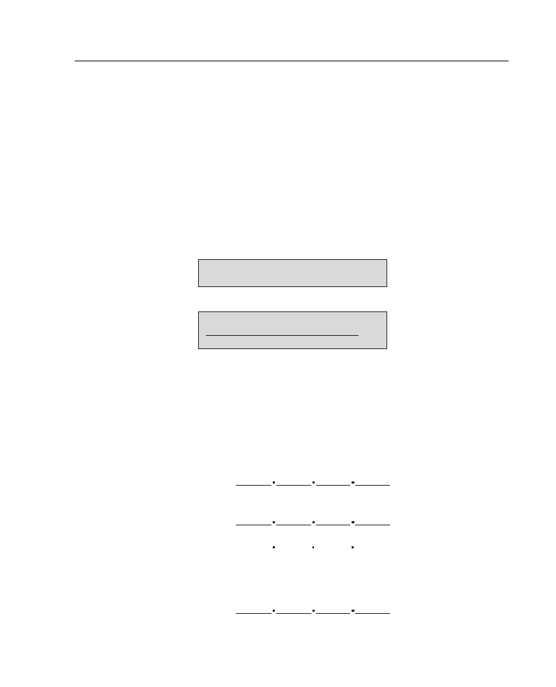
Figure A-1 is a job aid to help you with various aspects of IP addressing, including how to
distinguish address classes, the number of subnets and hosts available with various subnet
masks, and how to interpret IP addresses.

3
Job Aids and Supplements
Figure A-1
IP Addresses and Subnetting Job Aid
Decimal-to-Binary Conversion Chart
The following can be used to convert from decimal to binary, and from binary to decimal:
Decimal
Binary
Decimal
Binary
Decimal
Binary
Decimal
Binary
0
00000000
64
01000000
128
10000000
192
11000000
1
00000001
65
01000001
129
10000001
193
11000001
2
00000010
66
01000010
130
10000010
194
11000010
3
00000011
67
01000011
131
10000011
195
11000011
4
00000100
68
01000100
132
10000100
196
11000100
5
00000101
69
01000101
133
10000101
197
11000101
6
00000110
70
01000110
134
10000110
198
11000110
7
00000111
71
01000111
135
10000111
199
11000111
8
00001000
72
01001000
136
10001000
200
11001000
9
00001001
73
01001001
137
10001001
201
11001001
10
00001010
74
01001010
138
10001010
202
11001010
11
00001011
75
01001011
139
10001011
203
11001011
12
00001100
76
01001100
140
10001100
204
11001100
13
00001101
77
01001101
141
10001101
205
11001101
First octet
(172 - Class B)
defines network
portion.
Of the part that
remains, the subnet
mask bits define the
subnet portion.
Whatever bits
remain define the
host portion.
Address
172.16.5.72
1000 0011 0001 0000 0000 0101 0100 1000
Subnet mask
255.255.255.192 1111 1111 1111 1111 1111 1111 1100 0000
Class
Net
host
First
octet
Standard mask
binary
A
B
C
N.H.H.H
N.N.H.H
N.N.N.H
1–126
128–191
192–223
1111 1111 0000 0000 0000 0000 0000 0000
1111 1111 1111 1111 0000 0000 0000 0000
1111 1111 1111 1111 1111 1111 0000 0000
S
u
b
n
e
t
t
i
n
g
1010 1100 0001 0000 0000 0101 0100 1000
1111 1111 1111 1111 1111 1111 1100 0000
0000 0101 0100 1000
1111 1111 1100 0000
00 1000
00 0000
Network
Subnet
Host
Subnet
bits
Subnet
mask
Number of
subnets
Number of
hosts
Class B
Class C
2
3
4
5
6
7
8
9
10
11
12
13
14
2
3
4
5
6
255.255.192.0
255.255.224.0
255.255.240.0
255.255.248.0
255.255.252.0
255.255.254.0
255.255.255.0
255.255.255.128
255.255.255.192
255.255.255.224
255.255.255.240
255.255.255.248
255.255.255.252
255.255.255.192
255.255.255.224
255.255.255.240
255.255.255.248
255.255.255.252
4
8
16
32
64
128
256
512
1024
2048
4096
8192
16384
4
8
16
32
64
16382
8190
4094
2046
1022
510
254
126
62
30
14
6
2
62
30
14
6
2

Extending IP Addressing Job Aids
4
14
00001110
78
01001110
142
10001110
206
11001110
15
00001111
79
01001111
143
10001111
207
11001111
16
00010000
80
01010000
144
10010000
208
11010000
17
00010001
81
01010001
145
10010001
209
11010001
18
00010010
82
01010010
146
10010010
210
11010010
19
00010011
83
01010011
147
10010011
211
11010011
20
00010100
84
01010100
148
10010100
212
11010100
21
00010101
85
01010101
149
10010101
213
11010101
22
00010110
86
01010110
150
10010110
214
11010110
23
00010111
87
01010111
151
10010111
215
11010111
24
00011000
88
01011000
152
10011000
216
11011000
25
00011001
89
01011001
153
10011001
217
11011001
26
00011010
90
01011010
154
10011010
218
11011010
27
00011011
91
01011011
155
10011011
219
11011011
28
00011100
92
01011100
156
10011100
220
11011100
29
00011101
93
01011101
157
10011101
221
11011101
30
00011110
94
01011110
158
10011110
222
11011110
31
00011111
95
01011111
159
10011111
223
11011111
32
00100000
96
01100000
160
10100000
224
11100000
33
00100001
97
01100001
161
10100001
225
11100001
34
00100010
98
01100010
162
10100010
226
11100010
35
00100011
99
01100011
163
10100011
227
11100011
36
00100100
100
01100100
164
10100100
228
11100100
37
00100101
101
01100101
165
10100101
229
11100101
38
00100110
102
01100110
166
10100110
230
11100110
39
00100111
103
01100111
167
10100111
231
11100111
40
00101000
104
01101000
168
10101000
232
11101000
41
00101001
105
01101001
169
10101001
233
11101001
42
00101010
106
01101010
170
10101010
234
11101010
43
00101011
107
01101011
171
10101011
235
11101011
Decimal
Binary
Decimal
Binary
Decimal
Binary
Decimal
Binary
continues
(Continued)

5
Job Aids and Supplements
Supplement 1: Addressing Review
This supplement reviews the basics of IP addresses, including the following:
•
Converting IP addresses between decimal and binary
•
Determining an IP address class
•
Extending an IP classful address using subnet masks
•
Calculating a subnet mask
•
Calculating the networks for a subnet mask
•
Using prefixes to represent a subnet mask
•
Review questions
44
00101100
108
01101100
172
10101100
236
11101100
45
00101101
109
01101101
173
10101101
237
11101101
46
00101110
110
01101110
174
10101110
238
11101110
47
00101111
111
01101111
175
10101111
239
11101111
48
00110000
112
01110000
176
10110000
240
11110000
49
00110001
113
01110001
177
10110001
241
11110001
50
00110010
114
01110010
178
10110010
242
11110010
51
00110011
115
01110011
179
10110011
243
11110011
52
00110100
116
01110100
180
10110100
244
11110100
53
00110101
117
01110101
181
10110101
245
11110101
54
00110110
118
01110110
182
10110110
246
11110110
55
00110111
119
01110111
183
10110111
247
11110111
56
00111000
120
01111000
184
10111000
248
11111000
57
00111001
121
01111001
185
10111001
249
11111001
58
00111010
122
01111010
186
10111010
250
11111010
59
00111011
123
01111011
187
10111011
251
11111011
60
00111100
124
01111100
188
10111100
252
11111100
61
00111101
125
01111101
189
10111101
253
11111101
62
00111110
126
01111110
190
10111110
254
11111110
63
00111111
127
01111111
191
10111111
255
11111111
Decimal
Binary
Decimal
Binary
Decimal
Binary
Decimal
Binary
(Continued)
Supplement 1: Addressing Review
6
Converting IP Addresses Between Decimal and Binary
An IP address is a 32-bit, two-level hierarchical number. It is hierarchical because the first
portion of the address represents the network, and the second portion of the address
represents the node (host).
The 32 bits are grouped into four octets, with 8 bits per octet. The value of each octet ranges
from 0 to 255 decimal, or 00000000 to 11111111 binary. IP addresses are usually written
in dotted-decimal notation—each of the four octets is written in decimal notation, and dots
are put between the octets. Figure A-2 illustrates how you convert an octet of an IP address
in binary to decimal notation.
Figure A-2
Converting an Octet of an IP Address from Binary to Decimal
It is important that you understand how this conversion is done because it is used when
calculating subnet masks, as discussed later in this section.
Figure A-3 shows three examples of converting IP addresses between binary and decimal.
Figure A-3
Examples of Converting IP Addresses Between Binary and Decimal
Value for each bit
Converting from binary to decimal
1
1
1
1
1
1
1
1
128
64
32
16
8
4
2
1 = 255
0
1
0
0
0
0
0
1
128
64
32
16
8
4
2
1
0 + 64 + 0 + 0 + 0 + 0 + 0 + 1 = 65
Binary
address:
Decimal
address:
Binary
address:
Decimal
address:
Binary
address:
Decimal
address:
00001010.00000001.00010111.0001001
10101100 00010010 01000001 10101010
10
1
23
19
11000000.10101000.00001110.00000110
192
168
14
6
172
18
65
170

7
Job Aids and Supplements
Determining an IP Address Class
To accommodate large and small networks, the Network Information Center (NIC)
segregated the 32-bit IP address into Classes A through E. The first few bits of the first octet
determine the class of an address; this then determines how many network bits and host bits
are in the address. This is illustrated for Class A, B, and C addresses in Figure A-4. Each
address class therefore allows for a certain number of network addresses and a certain
number of host addresses within a network. Table A-1 shows the address range, number of
networks, and number of hosts for each of the classes. (Note that Class D and E addresses
are used for other purposes, not for addressing hosts.)
Figure A-4
Determining an IP Address Class from the First Few Bits of an Address
NOTE
The network 127.0.0.0 is reserved for loopback.
Using classes to denote which portion of the address represents the network number and
which portion is the node or host address is referred to as classful addressing. Several issues
must be addressed with classful addressing, however. The number of available Class A, B,
and C addresses is finite. Another problem is that not all classes are useful for a midsize
organization, as illustrated in Table A-1. As can be expected, the Class B range is the most
Table A-1
IP Address Classes
Class
Address Range
Number of Networks
Number of Hosts
Class A
1.0.0.0 to 126.0.0.0
128 (2
7
)
16,777,214
Class B
128.0.0.0 to 191.255.0.0
16,386 (2
14
)
65,532
Class C
192.0.0.0 to 223.255.255.0
Approximately 2 million
(2
21
)
254
Class D
224.0.0.0 to
239.255.255.254
Reserved for multicast
addresses
—
Class E
240.0.0.0 to
254.255.255.255
Reserved for research
—
Network
Host
0
Network
Host
10
Network
Host
110
32 Bits
Class A
Class B
Class C

Supplement 1: Addressing Review
8
accommodating to a majority of today’s organizational network topologies. To maximize
the use of the IP addresses received by an organization regardless of the class,
subnet masks
were introduced.
Extending an IP Classful Address Using Subnet Masks
RFC 950 was written to address the problem of IP address shortage. It proposed a
procedure, called
subnet masking
, for dividing Class A, B, and C addresses into smaller
pieces, thus increasing the number of possible networks. A subnet mask is a 32-bit value
that identifies which bits in an address represent network bits and which represent host bits.
In other words, the router doesn’t determine the network portion of the address by looking
at the value of the first octet; it looks at the subnet mask associated with the address. In this
way, subnet masks enable you to extend the usage of an IP address. This is a way of making
an IP address a three-level hierarchy, as shown in Figure A-5.
Figure A-5
A Subnet Mask Determines How an IP Address Is Interpreted
To create a subnet mask for an address, use a 1 for each bit that you want to represent the
network or subnet portion of the address, and use a 0 for each bit that you want to represent
the node portion of the address. Note that the 1s in the mask are contiguous. The default
subnet masks for Class A, B, and C addresses are as shown Table A-2.
Calculating a Subnet Mask
Because subnet masks extend the number of network addresses that you can use by using
bits from the host portion, you do not want to randomly decide how many additional bits to
Table A-2
IP Address Default Subnet Masks
Class
Default Mask in Binary
Default Mask in Decimal
Class A
11111111.00000000.00000000.00000000
255.0.0.0
Class B
11111111.11111111.00000000.00000000
255.255.0.0
Class C
11111111.11111111.11111111.00000000
255.255.255.0
Based on value in first octet
Based on subnet mask
Network
Host
Network
Host
Subnet
32 Bits
Mask
9
Job Aids and Supplements
use for the network portion. Instead, you want to do some research to determine how many
network addresses you need to derive from your NIC-given IP address. For example,
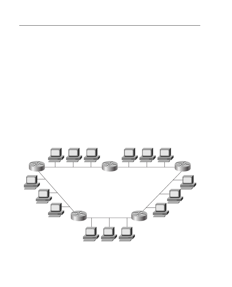
consider that you have IP address 172.16.0.0 and want to configure the network shown in
Figure A-6. To establish your subnet mask, you would do the following:
Step 1
Determine the number of networks (subnets) needed. In Figure A-6, for
example, there are five networks.
Step 2
Determine how many nodes per subnet must be defined. This example
has five nodes (two routers and three workstations) on each subnet.
Step 3
Determine future network and node requirements. For example, assume
100 percent growth.
Step 4
Given the information gathered from Steps 1 through 3, determine the
total number of subnets required. For this example, 10 subnets are
required. Refer to the “Job Aid: IP Addressing and Subnetting” section,
earlier in this appendix, and select the appropriate subnet mask value that
can accommodate 10 networks.
Figure A-6
Network Used in Subnet Mask Example
No mask exactly accommodates 10 subnets. Depending on your network growth trends,
you may select 4 subnet bits, resulting in a subnet mask of 255.255.240.0. The binary
representation of this subnet mask is as follows:
11111111.11111111.11110000.00000000
B
A
E
D
C
IP address = 172.16.0.0
1
2
3
1
2
3
1
2
3
1
2
3
1
2
3

Supplement 1: Addressing Review
10
The number of additional subnets given by
n
additional bits is 2
n
. For example, the
additional 4 subnet bits would give you 16 subnets.
Calculating the Networks for a Subnet Mask
For the example in Figure A-6, after you identify your subnet mask, you must calculate the
10 subnetted network addresses to use with 172.16.0.0 255.255.240.0. One way to do this
is as follows:
Step 1
Write the subnetted address in binary format, as shown at the top of
Figure A-7. Use the job aid “Decimal-to-Binary Conversion Chart,”
provided earlier in this appendix, if necessary.
Step 2
On the binary address, draw a line between the 16th and 17th bits, as
shown in Figure A-7. Then draw a line between the 20th and 21st bits.
Now you can focus on the target subnet bits.
Step 3
Historically, it was recommended that you begin choosing subnets from
highest (from the left-most bit) to lowest so that you could have available
network addresses. However, this strategy does not allow you to
adequately summarize subnet addresses, so the present recommendation
is to choose subnets from lowest to highest (right to left).
When calculating the subnet address, all the host bits are set to zero. To
convert back to decimal, it is important to note that you must always
convert an entire octet, 8 bits. For the first subnet, your subnet bits are
0000, and the rest of the octet (all host bits) is 0000.
Use the job aid “Decimal-to-Binary Conversion Chart,” provided earlier
in this appendix, if necessary, and locate this first subnet number. The
first subnet number would be 00000000, or decimal 0.
Step 4
(Optional) It is recommended that you list each subnet in binary form to
reduce the number of errors. In this way, you will not forget where you
left off in your subnet address selection.
Step 5
Locate the second-lowest subnet number. In this case, it would be 0001.
When combined with the next 4 bits (the host bits) of 0000, this is subnet
binary 00010000, or decimal 16.
Step 6
Continue locating subnet numbers until you have as many as you need—
in this case, 10 subnets, as shown in Figure A-7.

11
Job Aids and Supplements
Figure A-7
Calculating the Subnets for the Example in Figure A-6
Using Prefixes to Represent a Subnet Mask
As already discussed, subnet masks are used to identify the number of bits in an address
that represent the network, subnet, and host portions of the address. Another way of
indicating this is to use a
prefix
. A prefix is a slash (/) and a numerical value that is the sum
of the bits that represent the network and subnet portion of the address. For example, if you
were using a subnet mask of 255.255.255.0, the prefix would be /24 for 24 bits.
Table A-3 shows some examples of the different ways that you can represent a prefix and
subnet mask.
It is important to know how to write subnet masks and prefixes because Cisco routers use
both, as shown in Example A-1. You will typically be asked to input a subnet mask when
configuring an IP address, but the output generated using
show
commands typically shows
an IP address with a prefix.
Table A-3
Representing Subnet Masks
IP Address/Prefix
Subnet Mask in
Decimal
Subnet Mask in Binary
192.168.112.0/21
255.255.248.0
11111111.11111111.11111000.00000000
172.16.0.0/16
255.255.0.0
11111111.11111111.00000000.00000000
10.1.1.0/27
255.255.255.224
11111111.11111111.11111111.11100000
Assigned address: 172.16.0.0/16
In binary 10101100.00010000.00000000.00000000
Subnetted address: 172.16.0.0/20
In binary 10101100.00010000.xxxx 0000.00000000
1
st
subnet:
10101100 . 00010000 .0000 0000.00000000 = 172.16.0.0
2
nd
subnet:
172
.
16
.0001 0000.00000000 = 172.16.16.0
3
rd
subnet:
172
.
16
.0010 0000.00000000 = 172.16.32.0
4
th
subnet:
172
.
16
.0011 0000.00000000 = 172.16.48.0
.
.
10
th
subnet:
172
.
16
.1001 0000.00000000 = 172.16.144.0
Network
Subnet
Host

Supplement 1: Addressing Review
12
Supplement 1 Review Questions
Answer the following questions, and then refer to Appendix G, “Answers to the Review
Questions,” for the answers.
1
You need to design an IP network for your organization. Your organization’s IP
address is 172.16.0.0. Your assessment indicates that the organization needs at least
130 networks of no more than 100 nodes in each network.
As a result, you have decided to use a classful subnetting scheme based on the
172.16.0.0/24 scheme. In the space that follows, write any four IP addresses that are
part of the range of subnetwork numbers. Also, write the subnet address and subnet
mask for these addresses. One address is provided as an example.
2
Your network has the address 172.16.168.0/21. Write eight IP addresses in this
network.
Example A-1
Examples of Subnet Mask and Prefix Use on Cisco Routers
p1r3#
show run
<Output Omitted>
interface Ethernet0
ip address 10.64.4.1 255.255.255.0
!
interface Serial0
ip address 10.1.3.2 255.255.255.0
<Output Omitted>
p1r3#
show interface ethernet0
Ethernet0 is administratively down, line protocol is down
Hardware is Lance, address is 00e0.b05a.d504 (bia 00e0.b05a.d504)
Internet address is 10.64.4.1/24
<Output Omitted>
p1r3#
show interface serial0
Serial0 is down, line protocol is down
Hardware is HD64570
Internet address is 10.1.3.2/24
<Output Omitted>
IP Address
Subnet Address and Mask
172.16.1.0/24
172.16.1.0 255.255.255.0
13
Job Aids and Supplements
3
Write the four IP addresses in the range described by the 192.168.99.16/30 address.
4
Of the four addresses in question 3, which two could you use as host addresses in a
point-to-point connection?
Supplement 2: IP Access Lists
This supplement covers the following topics:
•
IP access list overview
•
IP standard access lists
•
IP extended access lists
•
Restricting virtual terminal access
•
Verifying access list configuration
•
Review questions
IP Access List Overview
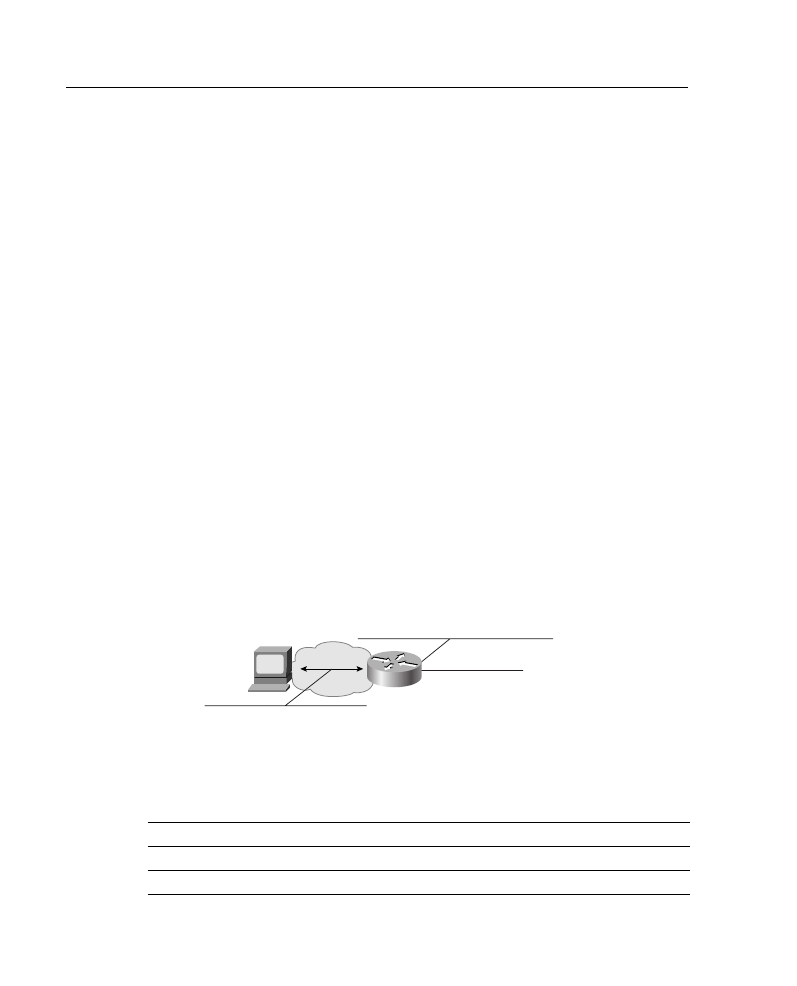
Packet filtering helps control packet movement through the network, as illustrated in Figure
A-8. Such control can help limit network traffic and restrict network use by certain users or
devices. To permit or deny packets from crossing specified router interfaces, Cisco provides
access lists. An IP access list is a sequential collection of permit and deny conditions that
apply to IP addresses or upper-layer IP protocols.
Figure A-8
Access Lists Control Packet Movement Through a Network
Table A-4 shows some of the available types of access lists on a Cisco router and their
access list numbers.
Table A-4
Access List Numbers
Type of Access List
Range of Access List Numbers
IP standard
1 to 99
IP extended
100 to 199
Transmission of packets on an interface
Virtual terminal line access (IP)

Supplement 2: IP Access Lists 14
This supplement covers IP standard and extended access lists. For information on other
types of access lists, refer to the technical documentation on Cisco’s web site at
www.cisco.com.
WARNING
The Cisco IOS Release 10.3 introduced substantial additions to IP access lists. These
extensions are backward compatible. Migrating from existing releases to the Cisco IOS
Release 10.3 or later image will convert your access lists automatically. However, previous
releases are not upwardly compatible with these changes. Thus, if you save an access list
with the Cisco IOS Release 10.3 or later image and then use older software, the resulting
access list will not be interpreted correctly. This incompatibility can cause security
problems. Save your old configuration file before booting Cisco IOS Release 10.3 (or later)
images in case you need to revert to an earlier version.
IP Standard Access Lists
This section discusses IP standard access list operation and implementation.
Standard access lists permit or deny packets based only on the source IP address of the
packet, as shown in Figure A-9. The access list number range for standard IP access lists is
1 to 99. Standard access lists are easier to configure than their more robust counterparts,
extended access lists.
Figure A-9
Standard IP Access Lists Filter Based Only on the Source Address
A standard access list is a sequential collection of permit and deny conditions that apply to
source IP addresses. The router tests addresses against the conditions in an access list one
Bridge type-code
200 to 299
IPX standard
800 to 899
IPX extended
900 to 999
IPX SAP
1000 to 1099
Table A-4
Access List Numbers (Continued)
Type of Access List
Range of Access List Numbers
172.16.5.0
Source address
10.0.0.3
15 Job Aids and Supplements
by one. The first match determines whether the router accepts or rejects the packet. Because
the router stops testing conditions after the first match, the order of the conditions is critical.
If no conditions match, the router rejects the packet.
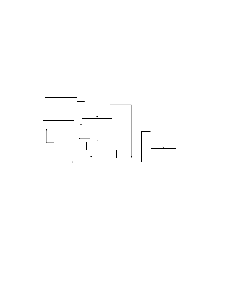
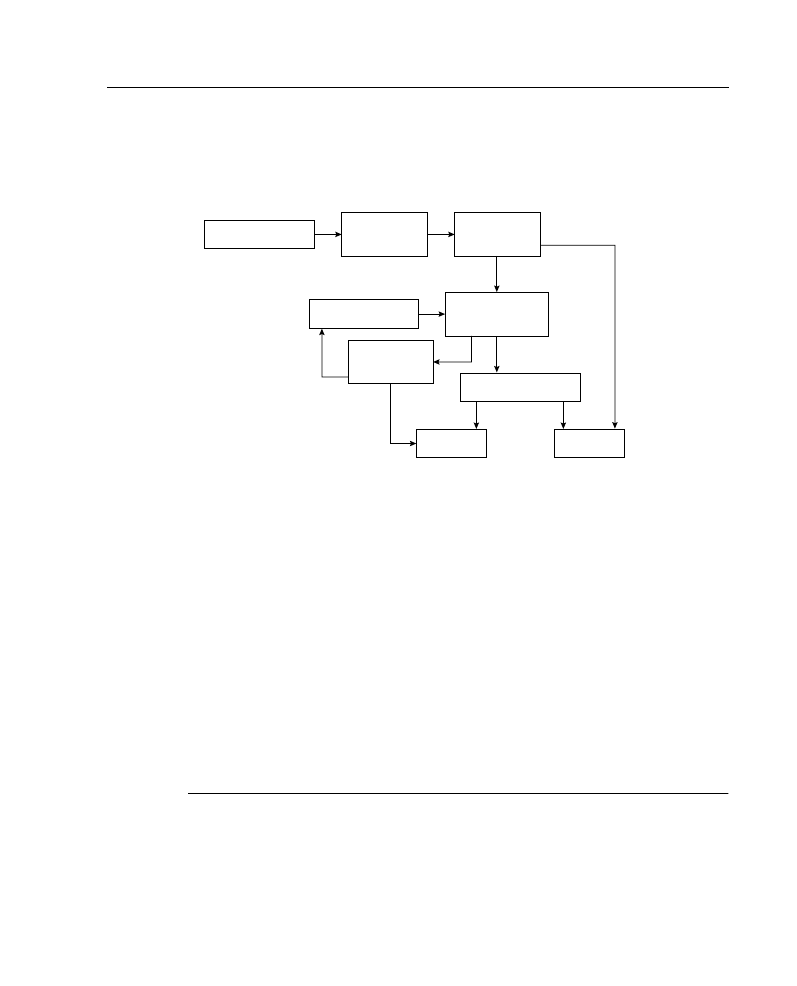
The processing of inbound standard access lists is illustrated in Figure A-10. After receiving
a packet, the router checks the source address of the packet against the access list. If the
access list permits the address, the router exits the access list and continues to process the
packet. If the access list rejects the address, the router discards the packet and returns an
Internet Control Message Protocol (ICMP) administratively prohibited message.
Figure A-10 Inbound Standard IP Access List Processing
Note that the action taken if no more entries are found in the access list is to deny the packet;
this illustrates an important concept to remember when creating access lists. The last entry
in an access list is what is known as an implicit deny any. All traffic not explicitly permitted
will be implicitly denied.
NOTE
When configuring access lists, order is important. Make sure that you list the entries in
order from specific to general. For example, if you want to deny a specific host address and
permit all other addresses, make sure that your entry about the specific host appears first.
The processing of outbound standard IP access lists is illustrated in Figure A-11. After
receiving and routing a packet to a controlled interface, the router checks the source address
of the packet against the access list. If the access list permits the address, the router
Incoming packet
Apply condition
Deny
Permit
More
entries?
Does source
address match?
Do route
table lookup
Route to
interface
Access list
on interface?
Next entry in list
Yes
Yes
Yes
No
No
No
ICMP Message
Process Packet
Supplement 2: IP Access Lists 16
transmits the packet. If the access list denies the address, the router discards the packet and
returns an ICMP administratively prohibited message.
Figure A-11 Outbound Standard IP Access List Processing
Both standard and extended IP access lists use a wildcard mask. Like an IP address, a
wildcard mask is a 32-bit quantity written in dotted-decimal format. The wildcard mask
tells the router which bits of the address to use in comparisons. Address bits corresponding
to wildcard mask bits set to 1 are ignored in comparisons; address bits corresponding to
wildcard mask bits set to 0 are used in comparisons.
An alternative way to think of the wildcard mask is as follows. If a 0 bit appears in the
wildcard mask, then the corresponding bit location in the access list address and the same
bit location in the packet address must match (either both must be 0 or both must be 1). If
a 1 bit appears in the wildcard mask, then the corresponding bit location in the packet will
match (whether it is 0 or 1), and that bit location in the access list address is ignored. For
this reason, bits set to 1 in the wildcard mask are sometimes called “don’t care” bits.
Remember that the order of the access list statements is important because the access list is
not processed further after a match has been found.
Wildcard Masks
The concept of a wildcard mask is similar to the wildcard character used in DOS-based
computers. For example, to delete all files on your computer that begin with the letter “f,”
you would type:
delete f*.*
Outgoing packet
Apply condition
Deny
Permit
More
entries?
Does source
address match?
Do route
table lookup
Access list
on interface?
Next entry in list
Yes
Yes
Yes
No
No
No
ICMP Message
Forward Packet

17 Job Aids and Supplements
The * character is the wildcard; any files that start with “f,” followed by any other
characters, then a dot, and then any other characters, will be deleted.
Instead of using wildcard characters, routers use wildcard masks to implement this concept.
Examples of addresses and wildcard masks, and what they match, are shown in
Table A-5.
Whether you are creating a standard or extended access list, you will need to complete the
following two tasks:
Step 1
Create an access list in global configuration mode by specifying an
access list number and access conditions.
Define a standard IP access list using a source address and wildcard, as
shown later in this section.
Define an extended access list using source and destination addresses, as
well as optional protocol-type information for finer granularity of
control, as shown in the “IP Extended Access Lists” section, later in this
supplement.
Step 2
Apply the access list in interface configuration mode to interfaces or
terminal lines.
After an access list is created, you can apply it to one or more interfaces.
Access lists can be applied on either outbound or inbound interfaces.
IP Standard Access List Configuration
Use the access-list access-list-number {permit | deny} {source source-wildcard | any}
[log] global configuration command to create an entry in a standard traffic filter list, as
detailed in Table A-6.
Table A-5
Access List Wildcard Mask Examples
Address
Wildcard Mask
Matches
0.0.0.0
255.255.255.255
Any address
172.16.0.0/16
0.0.255.255
Any host on network 172.16.0.0
172.16.7.11/16
0.0.0.0
Host address 172.16.7.11
255.255.255.255
0.0.0.0
Local broadcast address 255.255.255.255
172.16.8.0/21
0.0.7.255
Any host on subnet 172.16.8.0/21

Supplement 2: IP Access Lists 18
When a packet does not match any of the configured lines in an access list, the packet is
denied by default because there is an invisible line at the end of the access list that is
equivalent to deny any. (deny any is the same as denying an address of 0.0.0.0 with a
wildcard mask of 255.255.255.255.)
The keyword host can also be used in an access list; it causes the address that immediately
follows it to be treated as if it were specified with a mask of 0.0.0.0. For example,
configuring host 10.1.1.1 in an access list is equivalent to configuring 10.1.1.1 0.0.0.0.
Use the ip access-group access-list-number {in | out} interface configuration command to
link an existing access list to an interface, as shown in Table A-7. Each interface may have
both an inbound and an outbound IP access list.
Table A-6
Standard IP access-list Command Description
access-list Command
Description
access-list-number
Identifies the list to which the entry belongs, a number from 1
to 99.
permit | deny
Indicates whether this entry allows or blocks traffic from the
specified address.
source
Identifies the source IP address.
source-wildcard
(Optional) Identifies which bits in the address field must
match. A 1 in a bit position indicates “don’t care” bits, and a 0
in any bit position indicates that bit must strictly match. If this
field is omitted, the wildcard mask 0.0.0.0 is assumed.
any
Use this keyword as an abbreviation for a source and source-
wildcard of 0.0.0.0 255.255.255.255.
log
(Optional) Causes an informational logging message about
the packet that matches the entry to be sent to the console.
Exercise caution when using this keyword because it
consumes CPU cycles.
Table A-7
ip access-group Command Description
ip access-group Command
Description
access-list-number
Indicates the number of the access list to be linked to this
interface.
in | out
Processes packets arriving on or leaving from this interface.
Out is the default.

19 Job Aids and Supplements
Eliminate the entire list by typing the no access-list access-list-number global
configuration command. De-apply the access list with the no ip access-group access-list-
number {in | out} interface configuration command.
Implicit Wildcard Masks
Implicit, or default, wildcard masks reduce typing and simplify configuration, but care must
be taken when relying on the default mask.
The access list line shown in Example A-2 is an example of a specific host configuration.
For standard access lists, if no wildcard mask is specified, the wildcard mask is assumed to
be 0.0.0.0. The implicit mask makes it easier to enter a large number of individual
addresses.
Common errors found in access list lines are illustrated in Example A-3.
The first list in Example A-3—permit 0.0.0.0—would exactly match the address 0.0.0.0
and then permit it. In most cases, this address is illegal, so this list would prevent all traffic
from getting through (because of the implicit deny any at the end of the list).
The second list in Example A-3—permit 172.16.0.0—is probably a configuration error.
The intention is probably 172.16.0.0 0.0.255.255. The exact address 172.16.0.0 refers to the
network and would never be assigned to a host. As a result, nothing would get through with
this list, again because of the implicit deny any at the end of the list. To filter networks or
subnets, use an explicit wildcard mask.
The next two lines in Example A-3—deny any and deny 0.0.0.0 255.255.255.255—are
unnecessary to configure because they duplicate the function of the implicit deny that
occurs when a packet fails to match all the configured lines in an access list. Although not
necessary, you may want to add one of these entries for record-keeping purposes.
Configuration Principles
Following these general principles helps ensure that the access lists you create have the
intended results:
Example A-2
Standard Access List Using the Default Wildcard Mask
access-list 1 permit 172.16.5.17
Example A-3
Standard Access List Using the Default Wildcard Mask
access-list 1 permit 0.0.0.0
access-list 2 permit 172.16.0.0
access-list 3 deny any
access-list 3 deny 0.0.0.0 255.255.255.255
Supplement 2: IP Access Lists 20
•
Top-down processing
— Organize your access list so that more specific references in a network or
subnet appear before more general ones.
— Place more frequently occurring conditions before less frequent conditions.
•
Implicit deny any
— Unless you end your access list with an explicit permit any, it will deny by
default all traffic that fails to match any of the access list lines.
•
New lines added to the end
— Subsequent additions are always added to the end of the access list.
— You cannot selectively add or remove lines when using numbered access
lists, but you can when using IP named access lists (a feature available in
Cisco IOS Release 11.2 and later).
•
Undefined access list = permit any
— If you apply an access list with the ip access-group command to an
interface before any access list lines have been created, the result will be
permit any. The list is live, so if you enter only one line, it goes from a
permit any to a deny most (because of the implicit deny any) as soon as
you press Return. For this reason, you should create your access list before
you apply it to an interface.
Standard Access List Example
An example network is shown in Figure A-12, and the configuration on Router X in that
figure is shown in Example A-4.
Figure A-12 Network Used for Standard IP Access List Example
Consider which devices can communicate with Host A in this example:
X
10.51.0.0
E0
10.48.0.0
D
C
B
A
Internet
10.48.0.3
21 Job Aids and Supplements
•
Host B can communicate with Host A. It is permitted by the first line of the access list,
which uses an implicit host mask.
•
Host C cannot communicate with Host A. Host C is in the subnet denied by the second
line in the access list.
•
Host D can communicate with Host A. Host D is on a subnet that is explicitly
permitted by the third line of the access list.
•
Users on the Internet cannot communicate with Host A. Users outside of this network
are not explicitly permitted, so they are denied by default with the implicit deny any
at the end of the access list.
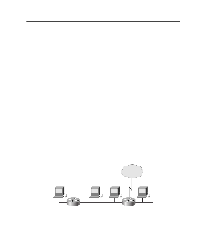
Location of Standard Access Lists
Access list location can be more of an art than a science, but some general guidelines can
be discovered by looking at the simple example illustrated in Figure A-13. An access list
configuration for this network is shown in Example A-5. If the policy goal is to deny Host
Z access to Host V on another network, and not to change any other access policy,
determine on which interface of which router this access list should be configured.
Figure A-13 Location of Standard IP Access List Example
Example A-4
Standard Access List Configuration of Router X in Figure A-12
Router(config)#access-list 2 permit 10.48.0.3
Router(config)#access-list 2 deny 10.48.0.0 0.0.255.255
Router(config)#access-list 2 permit 10.0.0.0 0.255.255.255
Router(config)#!(Note: all other access implicitly denied)
Router(config)#interface ethernet 0
Router(config-if)#ip access-group 2 in
Example A-5
Standard Access List to Be Configured on a Router in Figure A-13
access-list 3 deny 10.3.0.1
access-list 3 permit any
D
C
B
A
E1
E1
E1
E1
E0
E0
10.20.0.0
10.3.0.1
E0
E0
Z
Y
X
W
V

Supplement 2: IP Access Lists 22
The access list should be placed on Router A. The reason is that a standard access list can
specify only a source address. No hosts beyond the point in the path that the traffic is denied
can connect.
The access list could be configured as an outbound list on E0 of Router A, but it would most
likely be configured as an inbound list on E1 so that packets to be denied would not have
to be routed through Router A first.
Consider the effect of placing the access list on other routers:
•
Router B—Host Z could not connect with Host W (and Host V).
•
Router C—Host Z could not connect with hosts W and X (and Host V).
•
Router D—Host Z could not connect with hosts W, X, and Y (and Host V).
Thus, for standard access lists, the rule is to place them as close to the destination router as
possible to exercise the most control. Note, however, that this means that traffic is routed
through the network, only to be denied close to its destination.
IP Extended Access Lists
This section discusses extended access list operation and implementation.
Standard access lists offer quick configuration and low overhead in limiting traffic based on
source address within a network. Extended access lists provide a higher degree of control
by enabling filtering based on the source and destination addresses, transport layer
protocol, and application port number. These features make it possible to limit traffic based
on the uses of the network.
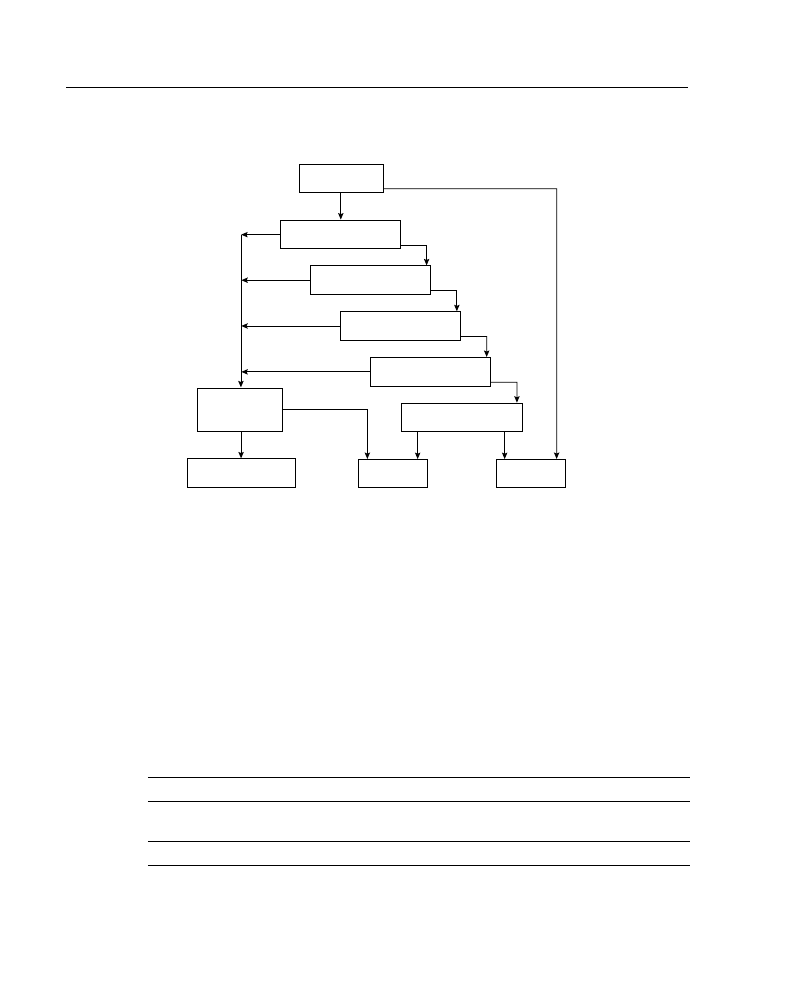
Extended Access List Processing
As shown in Figure A-14, every condition tested in a line of an extended access list must
match for the line of the access list to match and for the permit or deny condition to be
applied. As soon as one parameter or condition fails, the next line in the access list is
compared.
23 Job Aids and Supplements
Figure A-14 Extended IP Access List Processing Flow
The extended access list checks source address, destination address, and protocol.
Depending on the protocol configured, there may be more protocol-dependent options
tested. For example, a TCP port may be checked, which allows routers to filter at the
application layer.
Extended IP Access List Configuration
Use the access-list access-list-number {permit | deny} {protocol | protocol-keyword}
{source source-wildcard | any} {destination destination-wildcard | any} [protocol-specific
options] [log] global configuration command to create an entry in an extended traffic filter
list, as described in Table A-8.
Table A-8
Extended IP access-list Command Description
access-list Command
Description
access-list-number
Identifies the list to which the entry belongs, a number from
100 to 199.
permit | deny
Indicates whether this entry allows or blocks traffic.
* If present in access list
Access list?
Source address
Destination address
Protocol?*
Protocol options?*
Apply condition
Deny
Permit
More
entries?
Next entry in list
Does not
match
Yes
Yes
Match
No
No
Match
Match
Match
ICMP Message
Forward Packet

Supplement 2: IP Access Lists 24
The wildcard masks in an extended access list operate the same way as they do in standard
access lists. The keyword any in either the source or the destination position matches any
address and is equivalent to configuring an address of 0.0.0.0 with a wildcard mask of
255.255.255.255. An example of an extended access list is shown in Example A-6.
The keyword host can be used in either the source or the destination position; it causes the
address that immediately follows it to be treated as if it were specified with a mask of
0.0.0.0. An example is shown in Example A-7.
Use the access-list access-list-number {permit | deny} icmp {source source-wildcard |
any} {destination destination-wildcard | any} [icmp-type [icmp-code] | icmp-message]
global configuration command to filter ICMP traffic. The protocol keyword icmp indicates
protocol
ip, tcp, udp, icmp, igmp, gre, igrp, eigrp, ospf, nos, or a
number in the range of 0 through 255. To match any Internet
protocol, use the keyword ip. Some protocols have more
options that are supported by an alternate syntax for this
command, as shown later in this section.
source and destination
Identifies the source and destination IP addresses.
source-wildcard and destination-
wildcard
Identifies which bits in the address field must match. A 1 in a
bit position indicates “don’t care” bits, and a 0 in any bit
position indicates that the bit must strictly match.
any
Use this keyword as an abbreviation for a source and source-
wildcard, or a destination and destination-wildcard of 0.0.0.0
255.255.255.255.
log
(Optional) Causes informational logging messages about a
packet that matches the entry to be sent to the console.
Exercise caution when using this keyword because it
consumes CPU cycles.
Example A-6
Use of the Keyword any
access-list 101 permit ip 0.0.0.0 255.255.255.255 0.0.0.0 255.255.255.255
! (alternate configuration)
access-list 101 permit ip any any
Example A-7
Use of the Keyword host
access-list 101 permit ip 0.0.0.0 255.255.255.255 172.16.5.17 0.0.0.0
! (alternate configuration)
access-list 101 permit ip any host 172.16.5.17
Table A-8
Extended IP access-list Command Description (Continued)
access-list Command
Description

25 Job Aids and Supplements
that an alternate syntax is being used for this command and that protocol-specific options
are available, as described in Table A-9.
Cisco IOS Release 10.3 and later versions provide symbolic names that make configuration
and reading of complex access lists easier. With symbolic names, it is no longer critical to
understand the meaning of the ICMP message type and code (for example, message 8 and
message 0 can be used to filter the ping command). Instead, the configuration can use
symbolic names (for example, the echo and echo-reply symbolic names can be used to
filter the ping command), as shown in Table A-10. (You can use the Cisco IOS context-
sensitive help feature by entering ? when entering the access-list command, to verify the
available names and proper command syntax.)
Table A-9
Extended IP access-list icmp Command Description
access-list icmp
Command
Description
access-list-number
Identifies the list to which the entry belongs, a number from 100
to 199.
permit | deny
Indicates whether this entry allows or blocks traffic.
source and destination
Identifies the source and destination IP addresses.
source-wildcard and
destination-wildcard
Identifies which bits in the address field must match. A 1 in a bit
position indicates “don’t care” bits, and a 0 in any bit position
indicates that the bit must strictly match.
any
Use this keyword as an abbreviation for a source and source-
wildcard, or a destination and destination-wildcard of 0.0.0.0
255.255.255.255.
icmp-type
(Optional) Packets can be filtered by ICMP message type. The
type is a number from 0 to 255.
icmp-code
(Optional) Packets that have been filtered by ICMP message type
can also be filtered by ICMP message code. The code is a number
from 0 to 255.
icmp-message
(Optional) Packets can be filtered by a symbolic name
representing an ICMP message type or a combination of ICMP
message type and ICMP message code. A list of these names is
provided in Table A-10.
Table A-10
ICMP Message and Type Names
Administratively-prohibited
Information-reply
Precedence-unreachable
Alternate-address
Information-request
Protocol-unreachable
Conversion-error
Mask-reply
Reassembly-timeout
Dod-host-prohibited
Mask-request
Redirect

Supplement 2: IP Access Lists 26
Use the access-list access-list-number {permit | deny} tcp {source source-wildcard | any}
[operator source-port | source-port] {destination destination-wildcard | any} [operator
destination-port | destination-port] [established] global configuration command to filter
TCP traffic. The protocol keyword tcp indicates that an alternate syntax is being used for
this command and that protocol-specific options are available, as described in Table A-11.
Dod-net-prohibited
Mobile-redirect
Router-advertisement
Echo
Net-redirect
Router-solicitation
Echo-reply
Net-tos-redirect
Source-quench
General-parameter-problem
Net-tos-unreachable
Source-route-failed
Host-isolated
Net-unreachable
Time-exceeded
Host-precedence-unreachable
Network-unknown
Timestamp-reply
Host-redirect
No-room-for-option
Timestamp-request
Host-tos-redirect
Option-missing
Traceroute
Host-tos-unreachable
Packet-too-big
Ttl-exceeded
Host-unknown
Parameter-problem
Unreachable
Host-unreachable
Port-unreachable
Table A-11
Extended IP access-list tcp Command Description
access-list tcp Command
Description
access-list-number
Identifies the list to which the entry belongs, a number
from 100 to 199.
permit | deny
Indicates whether this entry allows or blocks traffic.
source and destination
Identifies the source and destination IP addresses.
source-wildcard and destination-
wildcard
Identifies which bits in the address field must match. A 1
in a bit position indicates “don’t care” bits, and a 0 in any
bit position indicates that the bit must strictly match.
any
Use this keyword as an abbreviation for a source and
source-wildcard, or a destination and destination-wildcard
of 0.0.0.0 255.255.255.255.
operator
(Optional) A qualifying condition. Can be: lt, gt, eq, neq.
source-port and destination-port
(Optional) A decimal number from 0 to 65535 or a name
that represents a TCP port number.
established
(Optional) A match occurs if the TCP segment has the
ACK or RST bits set. Use this if you want a Telnet or
another activity to be established in one direction only.
Table A-10
ICMP Message and Type Names (Continued)

27 Job Aids and Supplements
established Keyword in Extended Access Lists
When a TCP session is started between two devices, the first segment sent has the SYN
(synchronize) code bit set but does not have the ACK (acknowledge) code bit set in the
segment header because it is not acknowledging any other segments. All subsequent
segments sent do have the ACK code bit set because they are acknowledging previous
segments sent by the other device. This is how a router can distinguish between a segment
from a device that is attempting to start a TCP session and a segment of an ongoing already
established session. The RST (reset) code bit is set when an established session is being
terminated.
When you configure the established keyword in a TCP extended access list, it indicates that
that access list statement should match only TCP segments in which the ACK or RST code
bit is set. In other words, only segments that are part of an already established session will
be matched; segments that are attempting to start a session will not match the access list
statement.
Table A-12 is a list of TCP port names that can be used instead of port numbers. Port
numbers corresponding to these protocols can be found by typing a ? in the place of a port
number, or by looking at RFC 1700, “Assigned Numbers.” (This RFC is available at URL
www.cis.ohio-state.edu/htbin/rfc/rfc1700.html.)
Other port numbers can also be found in RFC 1700, “Assigned Numbers.” A partial list of
the assigned TCP port numbers is shown in Table A-13.
Table A-12
TCP Port Names
Bgp
Hostname
Syslog
Chargen
Irc
Tacacs-ds
Daytime
Klogin
Talk
Discard
Kshell
telnet
Domain
Lpd
Time
Echo
nntp
Uucp
Finger
Pop2
Whois
ftp control
Pop3
www
ftp-data
Smtp
Gopher
Sunrpc

Supplement 2: IP Access Lists 28
Use the access-list access-list-number {permit | deny} udp {source source-wildcard |
any} [operator source-port | source-port] {destination destination-wildcard | any}
[operator destination-port | destination-port] global configuration command to filter UDP
traffic. The protocol keyword udp indicates that an alternate syntax is being used for this
command and that protocol-specific options are available, as described in Table A-14.
Table A-13
Some Reserved TCP Port Numbers
Decimal
Keyword
Description
7
ECHO
Echo
9
DISCARD
Discard
13
DAYTIME
Daytime
19
CHARGEN
Character generator
20
FTP-DATA
File Transfer Protocol (data)
21
FTP-CONTROL
File Transfer Protocol
23
TELNET
Terminal connection
25
SMTP
Simple Mail Transfer Protocol
37
TIME
Time of day
43
WHOIS
Who is
53
DOMAIN
Domain name server
79
FINGER
Finger
80
WWW
World Wide Web HTTP
101
HOSTNAME
NIC host name server
Table A-14
Extended IP access-list udp Command Description
access-list udp Command
Description
access-list-number
Identifies the list to which the entry belongs, a number
from 100 to 199.
permit | deny
Indicates whether this entry allows or blocks traffic.
source and destination
Identifies the source and destination IP addresses.
source-wildcard and destination-
wildcard
Identifies which bits in the address field must match. A 1
in a bit position indicates “don’t care” bits, and a 0 in any
bit position indicates that bit must strictly match.
any
Use this keyword as an abbreviation for a source and
source-wildcard, or a destination and destination-wildcard
of 0.0.0.0 255.255.255.255.
continues

29 Job Aids and Supplements
Table A-15 is a list of UDP port names that can be used instead of port numbers. Port
numbers corresponding to these protocols can be found by typing a ? in the place of a port
number, or by looking at RFC 1700, “Assigned Numbers.”
Other port numbers can also be found in RFC 1700, “Assigned Numbers.” A partial list of
the assigned UDP port numbers is shown in Table A-16.
operator
(Optional) A qualifying condition. Can be: lt, gt, eq, neq.
source-port and destination-port
(Optional) A decimal number from 0 to 65535 or a name
that represents a UDP port number.
Table A-15
UDP Port Names
Biff
Nameserver
Syslog
Bootpc
NetBios-dgm
Tacasds-ds
Bootps
NetBios-ns
Talk
Discard
Ntp
Tftp
Dns
Rip
Time
Dnsix
Snmp
Whois
Echo
Snmptrap
Xdmcp
Mobile-ip
Sunrpc
Table A-16
Some Reserved UDP Port Numbers
Decimal
Keyword
Description
7
ECHO
Echo
9
DISCARD
Discard
37
TIME
Time of day
42
NAMESERVER
Host name server
43
WHOIS
Who is
53
DNS
Domain name server
67
BOOTPS
Bootstrap protocol server
68
BOOTPC
Bootstrap protocol client
69
TFTP
Trivial File Transfer Protocol
123
NTP
Network Time Protocol
137
NetBios-ns
NetBios Name Service
Table A-14
Extended IP access-list udp Command Description (Continued)
access-list udp Command
Description
Supplement 2: IP Access Lists 30
Extended Access List Examples
In the example shown in Figure A-15, Router A’s interface Ethernet 1 is part of a Class B
subnet with the address 172.22.3.0, Router A’s interface Serial 0 is connected to the
Internet, and the e-mail server’s address is 172.22.1.2. The access list configuration applied
to Router A is shown in Example A-8.
Figure A-15 Network Used for Extended IP Access List Example
In Example A-8, access list 104 is applied inbound on Router A’s Serial 0 interface.
The keyword established is used only for the TCP protocol to indicate an established
connection. A match occurs if the TCP segment has the ACK or RST bits set, which indicate
that the packet belongs to an existing connection. If the session is not already established
(the ACK bit is not set and the SYN bit is set), it means that someone on the Internet is
attempting to initialize a session, in which case the packet is denied. This configuration also
permits SMTP traffic from any address to the e-mail server. UDP domain name server
packets and ICMP echo and echo-reply packets are also permitted, from any address to any
other address.
138
NetBios-dgm
NetBios Datagram Service
161
SNMP
SNMP
162
SNMPTrap
SNMP Traps
520
RIP
RIP
Example A-8
Configuration on Router A in Figure A-15
access-list 104 permit tcp any 172.22.0.0 0.0.255.255 established
access-list 104 permit tcp any host 172.22.1.2 eq smtp
access-list 104 permit udp any any eq dns
access-list 104 permit icmp any any echo
access-list 104 permit icmp any any echo-reply
!
interface serial 0
ip access-group 104 in
Table A-16
Some Reserved UDP Port Numbers (Continued)
Decimal
Keyword
Description
A
172.22.1.0
172.22.3.0
E1
A
B
172.22.1.2
Internet
S0
E0
E-mail
server
31 Job Aids and Supplements
Another example is shown in Figure A-16. The access list configuration applied to Router
A is shown in Example A-9.
Figure A-16 Extended IP Access List Example with Many Servers
In Example A-9, access list 118 is applied outbound on Router A’s Ethernet 0 interface.
With the configuration shown in Example A-9, replies to queries from the Client A browser
to the Internet will be allowed back into the corporate network (because they are established
sessions). Browser queries from external sources are not explicitly allowed and will be
discarded by the implicit deny any at the end of the access list.
The access list in Example A-9 also allows e-mail (SMTP) to be delivered exclusively to
the mail server. The name server is permitted to resolve DNS requests. The 172.22.1.0
subnet is controlled by the network management group located at the NOC server (Client
B), so network-management queries (Simple Network Management Protocol [SNMP]) will
be allowed to reach these devices in the server farm. Attempts to ping the corporate network
from outside or from subnet 172.22.3.0 will fail because the access list blocks the echo
requests. However, the replies to echo requests generated from within the corporate
network will be allowed to re-enter the network.
Example A-9
Configuration on Router A in Figure A-16
access-list 118 permit tcp any 172.22.0.0 0.0.255.255 eq www established
access-list 118 permit tcp any host 172.22.1.2 eq smtp
access-list 118 permit udp any any eq dns
access-list 118 permit udp 172.22.3.0 0.0.0.255 172.22.1.0 0.0.0.255 eq snmp
access-list 118 deny icmp any 172.22.0.0 0.0.255.255 echo
access-list 118 permit icmp any any echo-reply
!
interface ethernet 0
ip access-group 118 out
A
B
172.22.1.0
172.22.2.0
172.22.3.0
E1
A
B
Browser
Internet
S0
E0
DNS
FTP
172.22.1.2
E-mail
NOC

Supplement 2: IP Access Lists 32
Location of Extended Access Lists
Because extended access lists can filter on more than source address, location is no longer
a constraint as it was when considering the location of a standard access list. Frequently,
policy decisions and goals are the driving forces behind extended access list placement.
If your goal is to minimize traffic congestion and maximize performance, you might want
to push the access lists close to the source to minimize cross-traffic and administratively
prohibited ICMP messages. If your goal is to maintain tight control over access lists as part
of your network security strategy, you might want to have them more centrally located.
Notice how changing network goals will affect access list configuration.
Some things to consider when placing extended access lists include the following:
•
Minimize distance traveled by traffic that will be denied (and ICMP unreachable
messages).
•
Keep denied traffic off the backbone.
•
Select the router to receive CPU overhead from access lists.
•
Consider the number of interfaces affected.
•
Consider access list management and security.
•
Consider network growth impacts on access list maintenance.
Restricting Virtual Terminal Access
This section discusses how standard access lists can be used to limit virtual terminal access.
Standard and extended access lists will block packets from going through the router. They
are not designed to block packets that originate within the router. An outbound Telnet
extended access list does not prevent router-initiated Telnet sessions, by default.
For security purposes, users can be denied virtual terminal (vty) access to the router, or
users can be permitted vty access to the router but denied access to destinations from that
router. Restricting virtual terminal access is less a traffic control mechanism than one
technique for increasing network security.
Because vty access is accomplished using the Telnet protocol, there is only one type of vty
access list.
How to Control vty Access
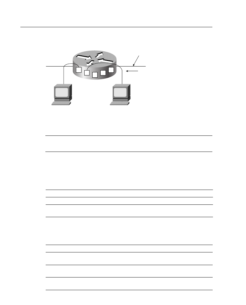
Just as a router has physical ports or interfaces such as Ethernet 0 and Ethernet 1, it also has
virtual ports. These virtual ports are called virtual terminal lines. By default, there are five
such virtual terminal lines, numbered vty 0 through 4, as shown in Figure A-17.
33 Job Aids and Supplements
Figure A-17 A Router Has Five Virtual Terminal Lines (Virtual Ports) by Default
You should set identical restrictions on all virtual terminal lines because you cannot control
on which virtual terminal line a user will connect.
NOTE
Some experts recommend that you configure one of the vty terminal lines differently than
the others. This way you will have a “back door” into the router.
Virtual Terminal Line Access Configuration
Use the line vty {vty-number | vty-range} global configuration command to place the router
in line configuration mode, as described in Table A-17.
Use the access-class access-list-number {in | out} line configuration command to link an
existing access list to a terminal line or range of lines, as described in Table A-18.
Table A-17
line vty Command Description
line vty Command
Description
vty-number
Indicates the number of the vty line to be configured.
vty-range
Indicates the range of vty lines to which the configuration will
apply.
Table A-18
access-class Command Description
access-class Command
Description
access-list-number
Indicates the number of the standard access list to be linked to a
terminal line. This is a decimal number from 1 to 99.
in
Prevents the router from receiving incoming connections from the
addresses in the access list.
out
Prevents someone from initiating a Telnet to addresses defined in
the access list.
0
1
2
3
4
Router
#
Router
#
Virtual ports (vty 0 through 4)
Physical port (E0)

Supplement 2: IP Access Lists 34
NOTE
When using the out keyword in the access-class command, the addresses in the specified
standard access list are treated as destination addresses rather than source addresses.
In the example configuration in Example A-10, any device on network 192.168.55.0 is
permitted to establish a virtual terminal (Telnet) session with the router. Of course, the user
must know the appropriate passwords to enter user mode and privileged mode.
Notice that in this example, identical restrictions have been set on all virtual terminal lines
(0 to 4) because you cannot control on which virtual terminal line a user will connect. (Note
that the implicit deny any still applies to this alternate application of access lists.)
Verifying Access List Configuration
This section describes how to verify access list configuration.
Use the show access-lists [access-list-number | name] privileged EXEC command to
display access lists from all protocols, as described in Table A-19. If no parameters are
specified, all access lists will be displayed.
The system counts how many packets match each line of an extended access list; the
counters are displayed by the show access-lists command.
Example A-11 illustrates an example output from the show access-lists command. In this
example, the first line of the access list has been matched three times, and the last line has
been matched 629 times. The second line has not been matched.
Example A-10
Configuration to Restrict Telnet Access to a Router
access-list 12 permit 192.168.55.0 0.0.0.255
!
line vty 0 4
access-class 12 in
Table A-19
show access-list Command Description
show access-lists
Command
Description
access-list-number
(Optional) Number of the access list to display
name
(Optional) Name of the access list to display

35 Job Aids and Supplements
Use the show ip access-list [access-list-number | name] EXEC command to display IP
access lists, as described in Table A-20. If no parameters are specified, all IP access lists
will be displayed.
Use the clear access-list counters [access-list-number | name] EXEC command to clear
the counters for the number of matches in an extended access list, as described in Table
A-21. If no parameters are specified, the counters will be cleared for all access lists.
Use the show line [line-number] EXEC command to display information about terminal
lines. The line-number is optional and indicates the absolute line number of the line for
which you want to list parameters. If a line number is not specified, all lines are displayed.
Supplement 2 Review Questions
Answer the following questions, and then refer to Appendix G for the answers.
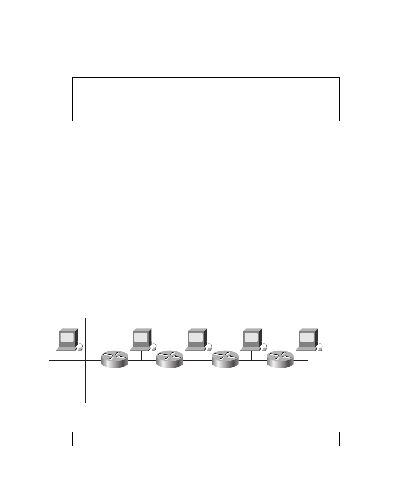
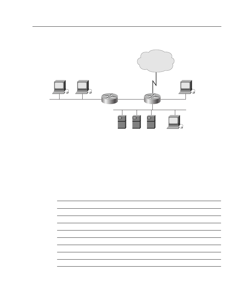
1
Figure A-18 shows the network for this question.
Create an access list and place it in the proper location to satisfy the following
requirements:
— Prevent all hosts on subnet 172.16.1.0/24, except host 172.16.1.3, from
accessing the web server on subnet 172.16.4.0. Allow all other hosts,
including from the outside world, to access the web server.
Example A-11
Output of the show access-lists Command
p1r1#show access-lists
Extended IP access list 100
deny tcp host 10.1.1.2 host 10.1.1.1 eq telnet (3 matches)
deny tcp host 10.1.2.2 host 10.1.2.1 eq telnet
permit ip any any (629 matches)
Table A-20
show ip access-list Command Description
show ip access-list
Command
Description
access-list-number
(Optional) Number of the IP access list to display
name
(Optional) Name of the IP access list to display
Table A-21
clear access-list counters Command Description
clear access-list
counters Command
Description
access-list-number
(Optional) Number of the access list for which to clear the counters
name
(Optional) Name of the access list for which to clear the counters
Supplement 2: IP Access Lists 36
Figure A-18 Network for Review Question 1
— Prevent the outside world from pinging subnet 172.16.4.0.
— Allow all hosts on all subnets of network 172.16.0.0 (using subnet mask
255.255.255.0) to send queries to the DNS server on subnet 172.16.4.0.
The outside world is not allowed to access the DNS server.
— Prevent host 172.16.3.3 from accessing subnet 172.16.4.0 for any reason.
— Prevent all other access to the 172.16.4.0 subnet.
Write your configuration in the spaces that follow. Be sure to include the router name
(A or B), interface name (E0, E1, or E2), and access list direction (in or out).
Global commands:
Interface commands:
Non-
172.16.0.0
B
A
172.16.2.0
172.16.1.0
172.16.3.0
172.16.4.0
E1
E1
E0
E0
Y
W
172.16.1.4
172.16.1.3
X
Z
172.16.3.3
S0
E2
DNS
4.2
FTP
4.3
WWW
4.4
Client
4.5

37 Job Aids and Supplements
2
What do bits set to 1 in a wildcard mask indicate when matching an address?
3
By default, what happens to all traffic in an access list?
4
Where should an extended access list be placed to save network resources?
5
Using the keyword host in an access list is a substitute for using what value of a
wildcard mask?
Supplement 3: OSPF
This supplement covers the following OSPF-related topics:
•
Not-so-stubby areas
•
OSPF single-area configuration example
•
OSPF multiarea configuration example
OSPF Not-So-Stubby Areas
Not-so-stubby areas (NSSAs) were first introduced in Cisco IOS Release 11.2. NSSAs are
based on RFC 1587, “The OSPF NSSA Option.” NSSAs enable you to make a hybrid stub
area that can accept some autonomous system external routes, referred to as type 7 LSAs.
Type 7 LSAs may be originated by and advertised throughout an NSSA. Type 7 LSAs are
advertised only within a single NSSA; they are not flooded into the backbone area or any
other area by border routers, although the information that they contain can be propagated
into the backbone area by being translated into type 5 LSAs by the ABR. As with stub areas,
NSSAs do not receive or originate type 5 LSAs.
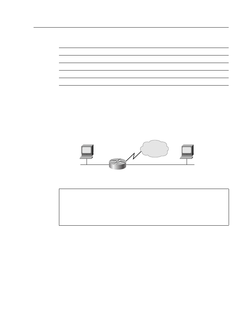
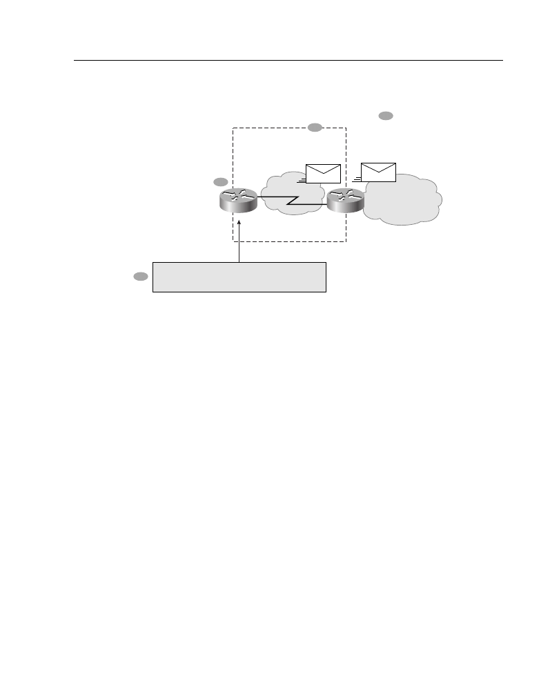
Use an NSSA if you are an Internet service provider (ISP) or a network administrator that
must connect a central site using Open Shortest Path First (OSPF) to a remote site using a
different protocol, such as the Routing Information Protocol (RIP) or Enhanced Interior
Gateway Routing Protocol (EIGRP), as shown in Figure A-19. You can use NSSA to
simplify the administration of this kind of topology.
Prior to NSSA, the limitation that a stub area cannot import external routes meant that the
connection between Router A and Router B in Figure A-19 could not be a stub area.
Therefore, if the connection ran OSPF, it would be a standard area and would import the
routes learned from RIP or EIGRP as type 5 LSAs. Because it is likely not desirable for the
branch office to get all the type 5 routes from the central site, Router B would be forced to
run OSPF and RIP or EIGRP.
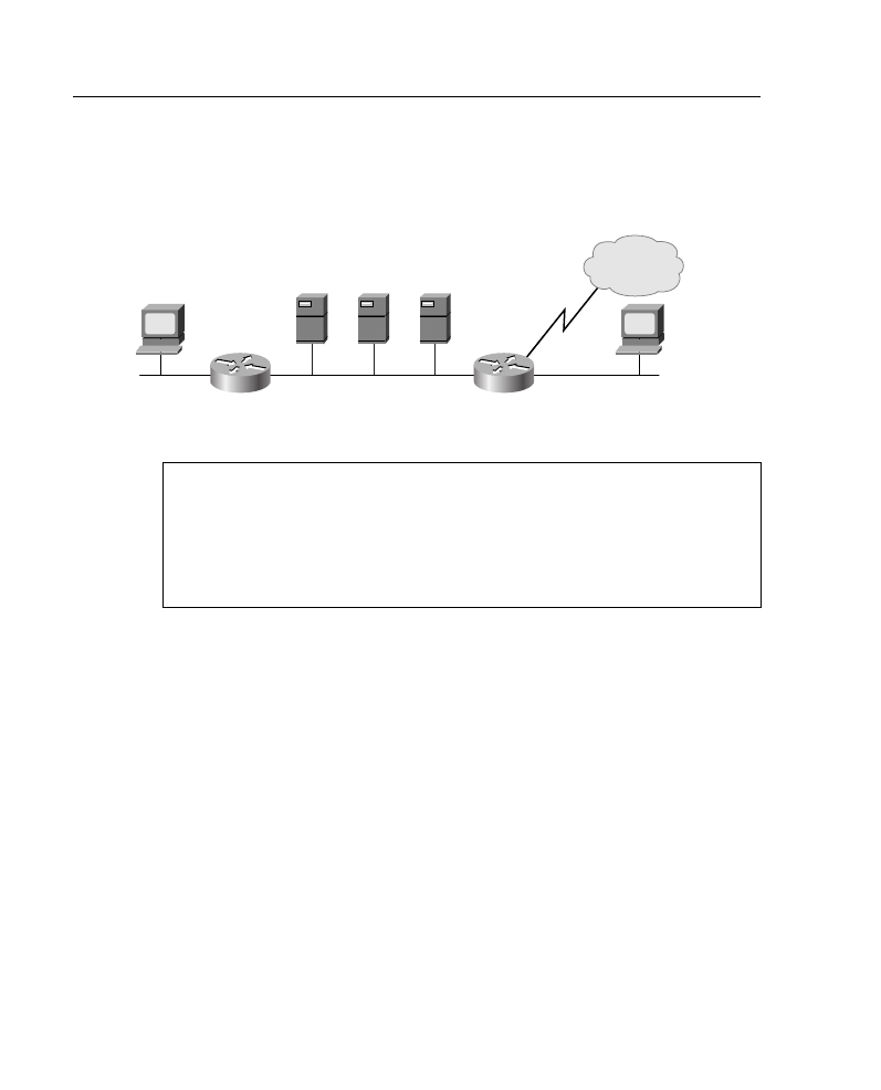
Now, with NSSA you can extend OSPF to cover the remote connection by defining the area
between the corporate router and the remote router as an NSSA, as shown in Figure A-19.
Supplement 3: OSPF 38
Figure A-19 Example of a Topology Where an NSSA Is Used
In Figure A-19, Router A is defined as an autonomous system boundary router (ASBR).
It is configured to exchange any routes within the RIP/EIGRP domain to the NSSA.
The following is what happens when using an NSSA:
1
Router A receives RIP or EGRP routes for networks 10.10.0.0/16, 10.11.0.0/16, and
192.168.1.0/24.
2
Router A, connected to the NSSA, imports the non-OSPF routes as type 7 LSAs into
the NSSA.
3
Router B, an ABR between the NSSA and the backbone area 0, receives the type 7
LSAs.
4
After the SPF calculation on the forwarding database, Router B translates the type 7
LSAs into type 5 LSAs and then floods them throughout backbone area 0.
At this point Router B could have summarized routes 10.10.0.0/16 and 10.11.0.0/16 as
10.0.0.0/8, or could have filtered one or more of the routes.
Configuring NSSA
The steps used to configure OSPF NSSA are as follows:
Step 1
On the ABR connected to the NSSA, configure OSPF, as described in
Chapter 3, “Configuring OSPF in a Single Area,” and Chapter 4,
“Interconnecting Multiple OSPF Areas.”
Step 2
Configure an area as NSSA using the following command, explained in
Table A-22:
Backbone Area 1
172.16.89.0/24
Central site
RIP or EIGRP
10.10.0.0/16
10.11.0.0/16
192.168.1.0/24
B
A
19.2 kbps
172.16.92.0
10.10.0.0/16
10.11.0.0/16
192.168.1.0/24
10.10.0.0/16
10.11.0.0/16
192.168.1.0/24
NSSA 1
Exchange 10.10.0.0, 10.11.0.0, and
192.168.1.0 to advertise to outside areas
Branch office
Type-7
Type-5
1
2
3
4

39 Job Aids and Supplements
router(config-router)#area
area-id nssa [no-redistribution]
[default-information-originate]
Step 3
Every router within the same area must agree that the area is NSSA;
otherwise, the routers will not be capable of communicating with each
other. Therefore, configure this command on every router in the NSSA
area.
Step 4
(Optional) Control the summarization or filtering during the translation,
using the following command explained in Table A-23:
router(config-router)#summary-address
address mask [prefix mask] [not-advertise]
[tag tag]
Figure A-20 and Example A-12 provide an example of NSSA configuration.
Table A-22
area nssa Command
Command
Description
area-id
Identifier of the area that is to be an NSSA. The identifier can be
specified as either a decimal value or an IP address.
no-redistribution
(Optional) Used when the router is an NSSA ABR and you want
the redistribute command to import routes only into the normal
areas, but not into the NSSA area.
default-information-
originate
(Optional) Used to generate a type 7 default into the NSSA area.
This argument takes effect only on the NSSA ABR.
Table A-23
summary-address Command
Command
Description
address
Summary address designated for a range of addresses
prefix
(Optional) IP route prefix for the destination
mask
(Optional) IP subnet mask used for the summary route
not-advertise
(Optional) Used to suppress routes that match the prefix/mask
pair
tag
(Optional) Tag value that can be used as a match value for
controlling redistribution via route maps
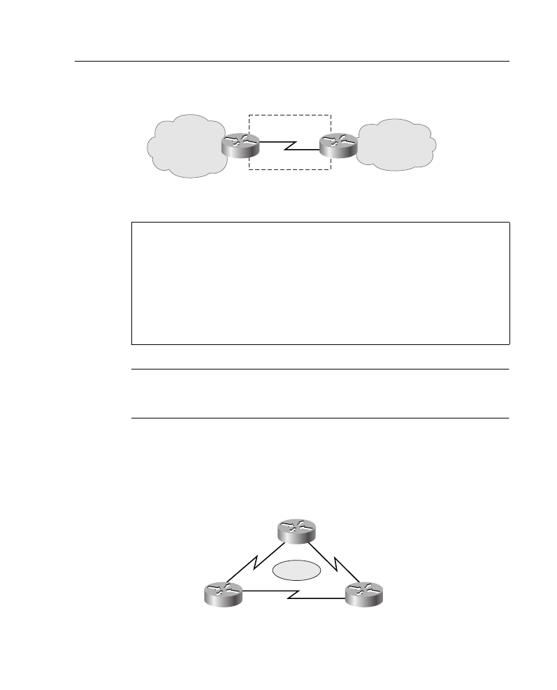
Supplement 3: OSPF 40
Figure A-20 Example of NSSA Topology
NOTE
The redistribute command shown in Example A-12 instructs the router to import RIP
packets into the OSPF network. Redistribution is discussed in detail in Chapter 8,
“Optimizing Routing Update Operation.”
OSPF Single-Area Configuration Example
This section includes configuration and show command output examples that result from
configuring the network shown in Figure A-21.
Figure A-21 OSPF Single-Area Topology
Example A-12
Configuring NSSA on the Routers in Figure A-20
Router A Configuration:
router ospf 1
redistribute rip subnets
network 172.16.92.0.0.0.255 area 1
area 1 nssa
Router B Configuration:
router ospf 1
summary-address 10.0.0.0.255.0.0.0
network 172.16.89.0.0.0.255 area 0
network 172.16.92.0.0.0.255 area 1
area 1 nssa
Backbone Area 0
172.16.89.0/24
RIP or EIGRP
10.10.0.0/16
10.11.0.0/16
192.168.1.0/24
B
A
172.16.92.0/24
NSSA1
19.2 kbps
P1R2
P1R1
P1R3
10.1.1.1/24
10.1.2.1/24
10.1.1.2/24
10.1.3.1/24
10.1.2.2/24
10.1.3.2/24
Area 0

41 Job Aids and Supplements
Example A-13 shows a typical configuration for single-area OSPF, for P1R3.
As shown in Example A-13, OSPF is activated on both Serial 0 and Serial 1 interfaces.
Example A-14 provides output of some show commands on P1R3. From the show ip route
output, you can confirm that OSPF is receiving OSPF routing information. From the show
ip ospf neighbor detail output, you can confirm that P1R3 has reached the full state with
Example A-13
P1R3 in Figure A-21 Configuration
P1R3#show run
Building configuration...
Current configuration:
!
version 11.2
no service password-encryption
no service udp-small-servers
no service tcp-small-servers
!
hostname P1R3
!
interface Ethernet0
no ip address
shutdown
!
interface Ethernet1
no ip address
shutdown
!
interface Serial0
ip address 10.1.3.2 255.255.255.0
no fair-queue
clockrate 64000
!
interface Serial1
ip address 10.1.2.2 255.255.255.0
!
router ospf 1
network 10.1.2.0 0.0.0.255 area 0
network 10.1.3.0 0.0.0.255 area 0
!
no ip classless
!
!
line con 0
exec-timeout 0 0
line aux 0
line vty 0 4
login
!
end

Supplement 3: OSPF 42
its two neighbors. From the show ip ospf database output, you can confirm that P1R3 is
receiving only type 1 LSAs—router link states LSA. No type 2 LSAs are received because
all the connections are point-to-point and, therefore, no designated router (DR) was elected.
OSPF Multiarea Configuration Example
This section includes configuration and show command output examples that result from
configuring the network shown in Figure A-22.
Example A-14
P1R3 in Figure A-21 Output for show ip route, show ip ospf neighbor detail, and show ip ospf
database Commands
P1R3#show ip route
Codes: C - connected, S - static, I - IGRP, R - RIP, M - mobile, B - BGP
D - EIGRP, EX - EIGRP external, O - OSPF, IA - OSPF inter area
N1 - OSPF NSSA external type 1, N2 - OSPF NSSA external type 2
E1 - OSPF external type 1, E2 - OSPF external type 2, E - EGP
i - IS-IS, L1 - IS-IS level-1, L2 - IS-IS level-2, * - candidate default
U - per-user static route, o - ODR
Gateway of last resort is not set
10.0.0.0/24 is subnetted, 3 subnets
C 10.1.3.0 is directly connected, Serial0
C 10.1.2.0 is directly connected, Serial1
O 10.1.1.0 [110/128] via 10.1.3.1, 00:01:56, Serial0
[110/128] via 10.1.2.1, 00:01:56, Serial1
P1R3#show ip ospf neighbor detail
Neighbor 10.1.3.1, interface address 10.1.3.1
In the area 0 via interface Serial0
Neighbor priority is 1, State is FULL
Options 2
Dead timer due in 00:00:34
Neighbor 10.1.2.1, interface address 10.1.2.1
In the area 0 via interface Serial1
Neighbor priority is 1, State is FULL
Options 2
Dead timer due in 00:00:36
P1R3#show ip ospf database
OSPF Router with ID (10.1.3.2) (Process ID 1)
Router Link States (Area 0)
Link ID ADV Router Age Seq# Checksum Link count
10.1.2.1 10.1.2.1 301 0x80000004 0x4A49 4
10.1.3.1 10.1.3.1 292 0x80000004 0x1778 4
10.1.3.2 10.1.3.2 288 0x80000004 0x5D2E 4
P1R3#
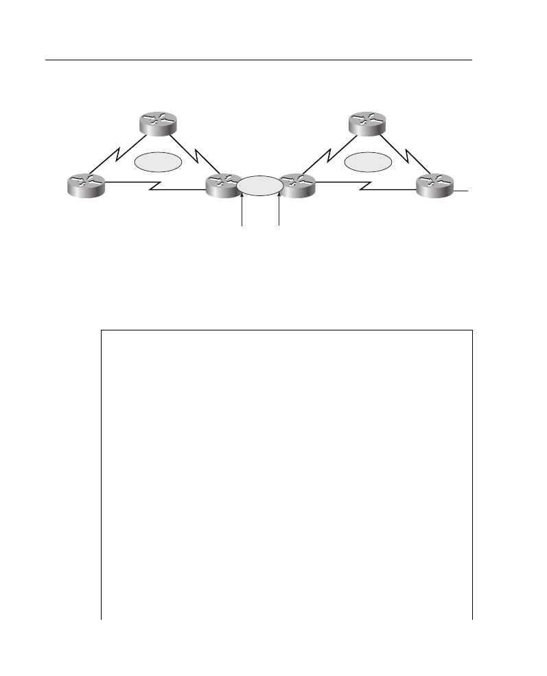
43 Job Aids and Supplements
Figure A-22 OSPF Multiarea Topology
Example A-15 provides output for P1R3 before any areas are configured for stub and route
summarization. You can observe that the OSPF database is quite large and has multiple
entries from type 1 (Router Link States), type 2 (Net Link States), and type 3 (Summary
Net Link States) LSAs.
Example A-15
P1R3 in Figure A-22 Output Prior to Stub and Route Summarization
P1R3#show ip ospf database
OSPF Router with ID (10.64.0.1) (Process ID 1)
Router Link States (Area 0)
Link ID ADV Router Age Seq# Checksum Link count
10.64.0.1 10.64.0.1 84 0x80000009 0x6B87 1
10.64.0.2 10.64.0.2 85 0x8000000C 0x6389 1
Net Link States (Area 0)
Link ID ADV Router Age Seq# Checksum
10.64.0.2 10.64.0.2 85 0x80000001 0x7990
Summary Net Link States (Area 0)
Link ID ADV Router Age Seq# Checksum
10.1.1.0 10.64.0.1 128 0x80000001 0x92D2
10.1.2.0 10.64.0.1 129 0x80000001 0x59F
10.1.3.0 10.64.0.1 129 0x80000001 0xF9A9
10.2.1.2 10.64.0.2 71 0x80000001 0x716F
10.2.2.1 10.64.0.2 41 0x80000001 0x7070
10.2.3.1 10.64.0.2 51 0x80000001 0x657A
Router Link States (Area 1)
Link ID ADV Router Age Seq# Checksum Link count
10.1.2.1 10.1.2.1 859 0x80000004 0xD681 4
P1R2
P1R1
P2R3
P2R1
P1R3
P2R2
10.1.1.1/24
10.1.2.1/24
10.2.1.1/24
10.2.2.1/24
10.1.1.2/24
10.1.3.1/24
10.2.3.1/24
10.1.2.2/24 10.2.1.2/24
10.2.2.2/24
10.1.3.2/24
10.2.3.2/24
10.64.0.1/24
10.64.0.2/24
Area 1
Area 2
Area 0

Supplement 3: OSPF 44
Example A-16 shows the configuration output for P1R3, a router that is an ABR for a stub
area and that is doing route summarization.
10.1.3.1 10.1.3.1 868 0x80000004 0xEB68 4
10.64.0.1 10.64.0.1 133 0x80000007 0xAF61 4
Summary Net Link States (Area 1)
Link ID ADV Router Age Seq# Checksum
10.2.1.2 10.64.0.1 74 0x80000001 0xDBFB
10.2.2.1 10.64.0.1 45 0x80000001 0xDAFC
10.2.3.1 10.64.0.1 55 0x80000001 0xCF07
10.64.0.0 10.64.0.1 80 0x80000003 0x299
P1R3#
Example A-16
P1R3 in Figure A-22 Configuration
P1R3#show run
Building configuration...
Current configuration:
!
version 11.2
no service password-encryption
no service udp-small-servers
no service tcp-small-servers
!
hostname P1R3
!
interface Ethernet0
ip address 10.64.0.1 255.255.255.0
!
interface Ethernet1
no ip address
shutdown
!
interface Serial0
ip address 10.1.3.2 255.255.255.0
no fair-queue
clockrate 64000
!
interface Serial1
ip address 10.1.2.2 255.255.255.0
!
router ospf 1
network 10.64.0.0 0.0.0.255 area 0
network 10.1.2.0 0.0.0.255 area 1
network 10.1.3.0 0.0.0.255 area 1
area 1 stub no-summary
area 1 range 10.1.0.0 255.255.0.0
Example A-15
P1R3 in Figure A-22 Output Prior to Stub and Route Summarization (Continued)
continues

45 Job Aids and Supplements
Example A-17 provides output from P1R3, after the network is configured with stub areas
and route summarization. The number of entries in the OSPF topology database is reduced.
!
no ip classless
!
!
line con 0
exec-timeout 0 0
line aux 0
line vty 0 4
login
!
end
Example A-17
P1R3 in Figure A-22 show ip ospf database Output After Stub and Route Summarization Were
Configured
P1R3#show ip ospf database
OSPF Router with ID (10.64.0.1) (Process ID 1)
Router Link States (Area 0)
Link ID ADV Router Age Seq# Checksum Link count
10.64.0.1 10.64.0.1 245 0x80000009 0x6B87 1
10.64.0.2 10.64.0.2 246 0x8000000C 0x6389 1
Net Link States (Area 0)
Link ID ADV Router Age Seq# Checksum
10.64.0.2 10.64.0.2 246 0x80000001 0x7990
Summary Net Link States (Area 0)
Link ID ADV Router Age Seq# Checksum
10.1.0.0 10.64.0.1 54 0x80000001 0x1B8B
10.2.0.0 10.64.0.2 25 0x80000001 0x9053
Router Link States (Area 1)
Link ID ADV Router Age Seq# Checksum Link count
10.1.2.1 10.1.2.1 1016 0x80000004 0xD681 4
10.1.3.1 10.1.3.1 1026 0x80000004 0xEB68 4
10.64.0.1 10.64.0.1 71 0x80000009 0xE9FF 2
Summary Net Link States (Area 1)
Link ID ADV Router Age Seq# Checksum
0.0.0.0 10.64.0.1 76 0x80000001 0x4FA3
P1R3#
Example A-16
P1R3 in Figure A-22 Configuration (Continued)

Supplement 4: EIGRP 46
Supplement 4: EIGRP
This supplement covers the following EIGRP-related topics:
•
IPX and EIGRP
•
AppleTalk and EIGRP
•
EIGRP configuration examples
IPX and EIGRP
The following section provides information on EIGRP for Novell IPX networks.
EIGRP for a Novell IPX network has the same fast routing and partial update capabilities
as EIGRP for IP. In addition, EIGRP has several capabilities that are designed to facilitate
the building of large, robust Novell IPX networks.
The first capability is support for incremental SAP updates. Novell IPX RIP routers send
out large RIP and SAP updates every 60 seconds. This can consume substantial amounts of
bandwidth. EIGRP for IPX sends out SAP updates only when changes occur and sends only
changed information.
The second capability that EIGRP adds to IPX networks is the capability to build large
networks. IPX RIP networks have a diameter limit of 15 hops. EIGRP networks can have
a diameter of 224 hops.
The third capability that EIGRP for Novell IPX provides is optimal path selection. The RIP
metric for route determination is based on ticks, with hop count used as a tie-breaker. If
more than one route has the same value for the tick metric, the route with the least number
of hops is preferred. Instead of ticks and hop count, IPX EIGRP uses a combination of these
metrics: delay, bandwidth, reliability, and load.
To add EIGRP to a Novell RIP and SAP network, configure EIGRP on the Cisco router
interfaces that connect to other Cisco routers also running EIGRP. Configure RIP and SAP
on the interfaces that connect to Novell hosts and or Novell routers that do not support
EIGRP. With EIGRP configured, periodic SAP updates are replaced with EIGRP
incremental updates when an EIGRP peer is found. However, note that unless RIP is
explicitly disabled for an IPX network number, both RIP and EIGRP will be active on the
interface associated with that network number.
Route Selection
IPX EIGRP routes are automatically preferred over RIP routes regardless of metrics unless
a RIP route has a hop count less than the external hop count carried in the EIGRP update—
for example, a server advertising its own internal network.

47 Job Aids and Supplements
Redistribution and Metric Handling
Redistribution is automatic between RIP and EIGRP, and vice versa. Automatic
redistribution can be turned off using the no redistribute command. Redistribution is not
automatic between different EIGRP autonomous systems.
Reducing SAP Traffic
Novell IPX RIP routers send out large RIP and SAP updates every 60 seconds regardless
of whether a change has occurred. These updates can consume a substantial amount of
bandwidth. You can reduce SAP update traffic by configuring EIGRP to do incremental
SAP updates. When EIGRP is configured for incremental SAP updates, the updates consist
only of information that has changed, and the updates are sent out only when a change
occurs, thus saving bandwidth.
When you configure EIGRP for incremental SAP updates, you can do the following:
•
Retain RIP, in which case only the reliable transport of EIGRP is used for sending
incremental SAP updates. (This is the preferred configuration over bandwidth-
sensitive connections.)
•
Turn off RIP, in which case EIGRP replaces RIP as the routing protocol.
AppleTalk and EIGRP
The following section provides information on EIGRP for AppleTalk network.
Cisco routers support AppleTalk Phase 1 and AppleTalk Phase 2. For AppleTalk Phase 2,
Cisco routers support both extended and nonextended networks.
To add EIGRP to an AppleTalk network, configure EIGRP on the Cisco router interfaces
that connect to other Cisco routers also running EIGRP. Do not disable Routing Table
Maintenance Protocol (RTMP) on the interfaces that connect to AppleTalk hosts or that
connect to AppleTalk routers that do not support EIGRP. RTMP is enabled by default when
AppleTalk routing is enabled and when an interface is assigned an AppleTalk cable range.
Route Selection
AppleTalk EIGRP routes are automatically preferred over RTMP routes. Whereas the
AppleTalk metric for route determination is based on hop count only, AppleTalk EIGRP
uses a combination of these configurable metrics: delay, bandwidth, reliability, and load.
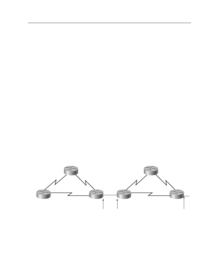
Supplement 4: EIGRP 48
Metric Handling
The formula for converting RTMP metrics to AppleTalk EIGRP metrics is hop count
multiplied by 252,524,800. This is a constant based on the bandwidth for a 9.6-kbps serial
line and includes an RTMP factor. An RTMP hop distributed into EIGRP appears as a
slightly worse path than an EIGRP-native, 9.6-kbps serial link. The formula for converting
EIGRP to RTMP is the value of the EIGRP external metric plus 1.
Redistribution
Redistribution between AppleTalk and EIGRP, and vice versa, is automatic by default.
Redistribution involves converting the EIGRP metric back into an RTMP hop count
metric. In reality, there is no conversion of an EIGRP composite metric into an RTMP
metric. Because a hop count is carried in an EIGRP metric tuple as the EIGRP route
spreads through the network, 1 is added to the hop count carried in the EIGRP metric
blocks through the network and put into any RTMP routing tuple generated.
There is no conversion of an EIGRP metric back into an RTMP metric because, in reality,
what RTMP uses as a metric (the hop count) is carried along the EIGRP metric all the way
through the network. This is true of EIGRP-derived routes and routes propagated through
the network that were originally derived from an RTMP route.
EIGRP Configuration Examples
This section includes configuration and show command output examples that result from
configuring the network shown in Figure A-23.
Figure A-23 Topology for the EIGRP Configuration Examples
P1R2
P1R1
P2R3
P2R1
P1R3
P2R2
10.1.1.1/24
10.1.2.1/24
10.2.1.1/24
10.2.2.1/24
10.1.1.2/24
10.1.3.1/24
10.2.3.1/24
10.1.2.2/24 10.2.1.2/24
10.2.2.2/24
10.1.3.2/24
10.2.3.2/24
10.64.0.1/24
10.64.0.2/24
Shutdown

49 Job Aids and Supplements
Example A-18 provides the configuration output for router P1R3 while running EIGRP.
Example A-18
P1R3 in Figure A-23 Configured for EIGRP
P1R3#show run
Building configuration...
Current configuration:
!
version 11.2
no service password-encryption
no service udp-small-servers
no service tcp-small-servers
!
hostname P1R3
!
enable password san-fran
!
no ip domain-lookup
ipx routing 0000.0c01.3333
ipx maximum-paths 2
!
interface Loopback0
no ip address
ipx network 1013
!
interface Ethernet0
ip address 10.64.0.1 255.255.255.0
!
interface Serial0
ip address 10.1.3.2 255.255.255.0
ipx input-sap-filter 1000
ipx network 1003
!
interface Serial1
ip address 10.1.2.2 255.255.255.0
ipx input-sap-filter 1000
ipx network 1002
clockrate 56000
!
<Output Omitted>
!
router eigrp 200
network 10.0.0.0
!
no ip classless
!
!
line con 0
exec-timeout 0 0
line aux 0
line vty 0 4
login
!
end

Supplement 4: EIGRP 50
Example A-19 shows the topology database of P1R3 running EIGRP before modifying the
bandwidth—in other words, all links are equal bandwidth. You can see that in the case of
equal-cost paths to the same network (10.1.1.0), both routes appear in the topology table as
successors.
Example A-20 shows the configuration output for P1R3 running EIGRP with bandwidth
and ip summary-address commands configured. The bandwidth on Serial 0 is changed
from its default of 1.544 Mbps to 64 kbps.
Example A-19
P1R3 in Figure A-23 EIGRP Topology Database Prior to Changing the bandwidth Value
P1R3#show ip eigrp topology
IP-EIGRP Topology Table for process 200
Codes: P - Passive, A - Active, U - Update, Q - Query, R - Reply,
r - Reply status
P 10.1.3.0/24, 1 successors, FD is 2169856
via Connected, Serial0
P 10.1.2.0/24, 1 successors, FD is 2169856
via Connected, Serial1
P 10.1.1.0/24, 2 successors, FD is 2681856
via 10.1.3.1 (2681856/2169856), Serial0
via 10.1.2.1 (2681856/2169856), Serial1
Example A-20
P1R3 in Figure A-23 Configuration for EIGRP with bandwidth and ip summary-address
Commands
P1R3#show run
Building configuration...
Current configuration:
!
version 11.2
no service password-encryption
no service udp-small-servers
no service tcp-small-servers
!
hostname P1R3
!
enable password san-fran
!
no ip domain-lookup
ipx routing 0000.0c01.3333
ipx maximum-paths 2
!
interface Loopback0
no ip address
ipx network 1013
!
interface Ethernet0
ip address 10.64.0.1 255.255.255.0
ip summary-address eigrp 200 10.1.0.0 255.255.0.0
!
continues

51 Job Aids and Supplements
Example A-21 shows the topology database of P1R3 running EIGRP, after modifying the
bandwidth on interface Serial 0 and summarizing addresses. You will notice that for
network 10.1.1.0, only one route appears as a successor.
interface Serial0
ip address 10.1.3.2 255.255.255.0
ipx input-sap-filter 1000
ipx network 1003
bandwidth 64
!
interface Serial1
ip address 10.1.2.2 255.255.255.0
ipx input-sap-filter 1000
ipx network 1002
clockrate 56000
!
<Output Omitted>
!
router eigrp 200
network 10.0.0.0
!
no ip classless
!
!
line con 0
exec-timeout 0 0
line aux 0
line vty 0 4
login
!
end
Example A-21
P1R3 in Figure A-23 EIGRP Topology Database After Applying the bandwidth and ip summary-
address Commands
P1R3#show ip eigrp topology
IP-EIGRP Topology Table for process 200
Codes: P - Passive, A - Active, U - Update, Q - Query, R - Reply, r - Reply status
P 10.1.3.0/24, 1 successors, FD is 40512000
via Connected, Serial0
via 10.1.2.1 (3193856/2681856), Serial1
P 10.1.2.0/24, 1 successors, FD is 2169856
via Connected, Serial1
P 10.1.1.0/24, 1 successors, FD is 2681856
via 10.1.2.1 (2681856/2169856), Serial1
Example A-20
P1R3 in Figure A-23 Configuration for EIGRP with bandwidth and ip summary-address
Commands (Continued)
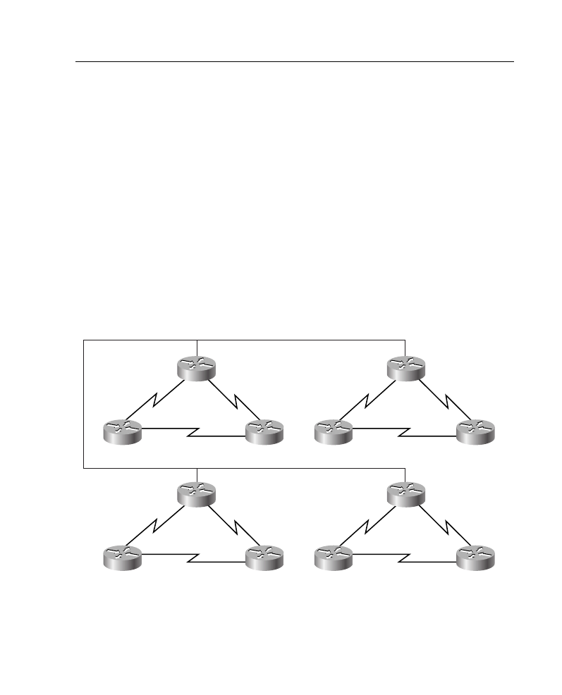
Supplement 5: BGP 52
Supplement 5: BGP
This supplement covers the following BGP-related topics:
•
BGP configuration output examples
•
Distribute lists
•
Route maps
•
Communities
•
Peer groups
BGP Configuration Output Examples
This section includes configuration and show command output examples that result from
configuring the network shown in Figure A-24. RIP is configured as the internal routing
protocol within the autonomous systems, and BGP is the external protocol between the
autonomous systems. BGP routes are redistributed into RIP.
Figure A-24 Example BGP/RIP Network
P1R2
P1R1
P2R3
P2R1
P1R3
P2R2
1.2.0.1/16
1.1.0.2/16
2.2.0.1/16
2.1.0.2/16
1.2.0.2/16
1.3.0.1/16
2.3.0.1/16
1.1.0.1/16
2.2.0.2/16
2.1.0.1/16
1.3.0.2/16
2.3.0.2/16
AS65501
AS65502
P3R2
P3R1
P4R3
P4R1
P3R3
P4R2
3.2.0.1/16
3.1.0.2/16
4.2.0.1/16
4.1.0.2/16
3.2.0.2/16
3.3.0.1/16
4.3.0.1/16
3.1.0.1/16
4.2.0.1/16
4.1.0.1/16
3.3.0.2/16
4.3.0.2/16
AS65503
AS65504
10.14.0.2/24
10.14.0.1/24
10.14.0.4/24
10.14.0.3/24

53 Job Aids and Supplements
Example of BGP/RIP Configuration for P1R1
Example A-22 shows part of the configuration for P1R1 in Figure A-24, running both RIP
and BGP.
In Example A-22, the network 10.0.0.0 command advertises network 10.0.0.0 in RIP so
that internal routers can see network 10.0.0.0. The passive-interface e0 command does not
allow RIP to advertise any routes on the backbone. The redistribute bgp 65501 metric 3
command redistributes BGP information into RIP, with a hop count of 3. The network
1.0.0.0 command under the BGP configuration advertises network 1.0.0.0 to each of Router
P1R1’s three BGP neighbors.
Example A-22
Configuration of P1R1 in Figure A-24
P1R1#show run
<output omitted>
!
interface Ethernet0
ip address 10.14.0.1 255.255.255.0
!
interface Serial0
ip address 1.1.0.2 255.255.0.0
!
interface Serial1
ip address 1.2.0.1 255.255.0.0
!
router rip
network 10.0.0.0
network 1.0.0.0
passive-interface e0
redistribute bgp 65501 metric 3
!
router bgp 65501
network 1.0.0.0
neighbor 10.14.0.2 remote-as 65502
neighbor 10.14.0.3 remote-as 65503
neighbor 10.14.0.4 remote-as 65504
!
no ip classless
!
<output omitted>

Supplement 5: BGP 54
Example of RIP Configuration for P1R2
Example A-23 shows part of the configuration for P1R2 in Figure A-24, one of the routers
running only RIP.
In Example A-23, the network 1.0.0.0 command starts up RIP on all interfaces that P1R2
has in network 1.0.0.0 and allows the router to advertise network 1.0.0.0.
Example Output of show ip route for P1R1
Example A-24 displays the output of the show ip route command on P1R1 in Figure A-24.
Example A-23
Configuration of P1R2 in Figure A-24
P1R2#show run
<output omitted>
!
interface Ethernet0
shutdown
!
interface Serial0
ip address 1.2.0.2 255.255.0.0
!
interface Serial1
ip address 1.3.0.1 255.255.0.0
!
router rip
network 1.0.0.0
!
no ip classless
!
<output omitted>
Example A-24
show ip route Command Output on P1R1 in Figure A-24
P1R1#show ip route
<output omitted>
1.0.0.0/16 is subnetted, 3 subnets
C 1.1.0.0 is directly connected, Serial0
R 1.3.0.0 [120/1] via 1.2.0.2, 00:00:25, Serial1
[120/1] via 1.1.0.1, 00:00:22, Serial0
C 1.2.0.0 is directly connected, Serial1
B 2.0.0.0/8 [20/0] via 10.14.0.2, 00:03:26
B 3.0.0.0/8 [20/0] via 10.14.0.3, 00:03:26
B 4.0.0.0/8 [20/0] via 10.14.0.4, 00:03:26
10.0.0.0/24 is subnetted, 1 subnets
C 10.14.0.0 is directly connected, Ethernet0
P1R1#

55 Job Aids and Supplements
The shaded lines in Example A-24 indicate the routes that P1R1 has learned from its BGP
neighbors.
Example Output of show ip route for P1R2
Example A-25 displays the output of the show ip route command on P1R2 in Figure A-24.
The shaded lines in Example A-25 indicate the routes that P1R2 has learned from P1R1, by
P1R1 redistributing them into RIP from BGP.
Distribute Lists
This section details the configuration of distribute lists for filtering BGP information.
The neighbor distribute-list {ip-address | peer-group-name} distribute-list access-list-
number in | out router configuration command is used to distribute BGP neighbor
information as specified in an access list. The parameters for this command are detailed in
Table A-24.
Example A-25
show ip route Command Output on P1R2 in Figure A-24
P1R2#show ip route
<output omitted>
1.0.0.0/16 is subnetted, 3 subnets
R 1.1.0.0 [120/1] via 1.2.0.1, 00:00:17, Serial0
[120/1] via 1.3.0.2, 00:00:26, Serial1
C 1.3.0.0 is directly connected, Serial1
C 1.2.0.0 is directly connected, Serial0
R 2.0.0.0/8 [120/3] via 1.2.0.1, 00:00:17, Serial0
R 3.0.0.0/8 [120/3] via 1.2.0.1, 00:00:17, Serial0
R 4.0.0.0/8 [120/3] via 1.2.0.1, 00:00:17, Serial0
R 10.0.0.0/8 [120/1] via 1.2.0.1, 00:00:17, Serial0
P1R2#
Table A-24
neighbor distribute-list Command Description
neighbor distribute-list
Command
Description
ip address
Gives the IP address of the BGP neighbor for which routes will be
filtered.
peer-group-name
Gives the name of a BGP peer group. (Peer groups are detailed in
the “Peer Groups” section later in this supplement.)
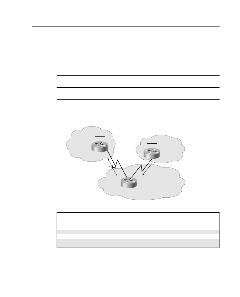
Supplement 5: BGP 56
Example A-26 provides a configuration for Router A in Figure A-25.
Figure A-25 Network for BGP Distribute List Example
In this example, Router A has two neighbors, Router B (10.10.10.2 in AS 65000) and
Router C (10.10.20.2 in AS 65500). When Router A sends updates to neighbor Router B,
access-list-number
Gives the number of a standard or extended access list. It can be
an integer from 1 to 199. (A named access list can also be
referenced.)
in
Indicates that the access list is applied to incoming advertisements
from the neighbor.
out
Indicates that the access list is applied to outgoing advertisements
to the neighbor.
Example A-26
Configuration of Router A in Figure A-25
RtrA(config)#router bgp 64520
RtrA(config-router)# network 192.168.1.0
RtrA(config-router)# neighbor 10.10.10.2 remote-as 65000
RtrA(config-router)# neighbor 10.10.20.2 remote-as 65500
RtrA(config-router)# neighbor 10.10.10.2 distribute-list 1 out
RtrA(config-router)# exit
RtrA(config)# access-list 1 deny 172.30.0.0 0.0.255.255
RtrA(config)# access-list 1 permit 0.0.0.0 255.255.255.255
Table A-24
neighbor distribute-list Command Description (Continued)
neighbor distribute-list
Command
Description
AS 65000
AS 65500
10.10.10.2
B
A
C
172.30.0.0
10.10.20.2
192.168.1.0
AS 64520
10.10.10.1
10.10.20.1
172.30.0.0
172.30.0.0
192.168.2.0

57 Job Aids and Supplements
the neighbor distribute-list statement specifies that it will use the access-list 1 to
determine which updates are to be sent.
Access list 1 specifies that any route starting with 172.30—in this case, the route to
172.30.0.0—should not be sent (it is denied in the access list). All other routes will be sent
to Router B. (Recall that because access lists have an implicit deny any at the end, the
permit statement is required in the access list for the other routes to be sent.)
As shown in Example A-26, a standard IP access list can be used to control the sending of
updates about a specific network number. However, if you need to control updates about
subnets and supernets of a network with a distribute list, extended access lists would be
required.
Extended Access List Use in a Distribute List
When an IP extended access list is used with a distribute list, the parameters have different
meanings than when the extended access list is used in other ways. The syntax of the IP
extended access list is the same as usual, with a source address and wildcard, and a
destination address and wildcard. However, the meanings of these parameters are different.
The source parameters of the extended access list are used to indicate the address of the
network whose updates are to be permitted or denied. The destination parameters of the
extended access list are used to indicate the subnet mask of that network.
The wildcard parameters indicate, for the network and subnet mask, which bits are relevant.
Network and subnet mask bits corresponding to wildcard bits set to 1 are ignored during
comparisons, and network and subnet mask bits corresponding to wildcard bits set to 0 are
used in comparisons.
The following example shows an extended access list:
access-list 101 ip permit 172.0.0.0 0.255.255.255 255.0.0.0 0.0.0.0
The interpretation of the previous access-list when used with a neighbor distribute-list
command is to permit only a route to network 172.0.0.0 255.0.0.0. Therefore, the list would
allow only the supernet 172.0.0.0/8 to be advertised. For example, assume that Router A
had routes to networks 172.20.0.0/16 and 172.30.0.0/16, and also had an aggregated route
to 172.0.0.0/8. The use of this access-list would allow only the supernet 172.0.0.0/8 to be
advertised; networks 172.20.0.0/16 and 172.30.0.0/16 would not be advertised.
Route Maps
Route maps were introduced in Chapter 8. They are reviewed here in the context of BGP
and for use in communities, discussed in the next section.
A route map is a method used to control and modify routing information. This is done by
defining conditions for redistributing routes from one routing protocol to another or
controlling routing information when injected into and out of BGP.

Supplement 5: BGP 58
Route maps are complex access lists that allow some conditions to be tested against the
route in question using match commands. If the conditions match, some actions can be
taken to modify the route. These actions are specified by set commands.
If the match criteria are met and the route map specifies permit, then the routes will be
controlled as specified by the set actions, and the rest of the route map list will be ignored.
If the match criteria are met and the route map specifies deny, then the routes will not be
controlled and the rest of the route-map list will be ignored.
If all sequences in the list are checked without a match, then the route will not be accepted
nor forwarded (this is the implicit deny any at the end of the route map).
match commands include the following:
•
match as-path
•
match community
•
match clns
•
match interface
•
match ip address
•
match ip next-hop
•
match ip route-source
•
match metric
•
match route-type
•
match tag
set commands include the following:
•
set as-path
•
set clns
•
set automatic-tag
•
set community
•
set interface
•
set default interface
•
set ip default next-hop
•
set level
•
set local-preference
•
set metric
•
set metric-type
•
set next-hop

59 Job Aids and Supplements
•
set origin
•
set tag
•
set weight
For example, the set local-preference value route map command is used to specify a
preference value for the autonomous system path. The value is the local preference value
from 0 to 4,294,967,295; a higher value is more preferred.
NOTE
A prefix list can be used as an alternative to an access list in the match {ip address | next-
hop | route-source} access-list command of a route map. The configuration of prefix lists
and access lists are mutually exclusive within the same sequence of a route map.
Configuring Route Maps for BGP Updates
The neighbor {ip-address | peer-group-name} route-map map-name {in | out} router
configuration command is used to apply a route map to incoming or outgoing BGP routes,
as detailed in Table A-25.
NOTE
When used for filtering BGP updates, route maps cannot be used to filter inbound updates
when using a match on the IP address. Filtering outbound updates is permitted.
Example A-27 shows BGP running on a router. A route map named changemetric is being
used when routes are sent out to neighbor 172.20.1.1.
Table A-25
neighbor route-map Command Description
neighbor route-map
Command
Description
ip-address
Gives the IP address of the BGP neighbor for which routes will be
filtered.
peer-group-name
Gives the name of a BGP peer group. (Peer groups are detailed in the
“Peer Groups” section, later in this supplement.)
map-name
Gives the name of the route map to apply.
in
Apply route map to incoming routes from the neighbor.
out
Apply route map to outgoing routes to the neighbor.

Supplement 5: BGP 60
NOTE
Other router bgp configuration commands have been omitted from the commands in
Example A-27.
In this example, two instances of changemetric have been defined. Sequence number 10
will be checked first. If a route’s IP address matches access list 1—in other words, if the IP
address starts with 172.16—the route will have its metric (MED) set to 2, and the rest of
the list will be ignored. If there is no match, then sequence number 20 will be checked.
Because there is no match statement in this instance, the metric (MED) on all other routes
will be set to 5.
NOTE
It is always very important to plan what will happen to routes that do not match any of the
route map instances because they will be dropped by default.
Communities
This section discusses BGP communities and how to configure them.
As discussed in Chapter 6, “Configuring Basic Border Gateway Protocol,” BGP
communities are another way to filter incoming or outgoing BGP routes. Distribute lists
and prefix lists (discussed in the previous section in this supplement, “Distribute Lists,”
and in Chapter 7, “Implementing BGP in Scalable Networks,” respectively) would be
cumbersome to configure for a large network with a complex routing policy. For example,
individual neighbor statements and access lists or prefix lists would need to be configured
for each neighbor on each router that was involved in the policy.
The BGP communities function allows routers to tag routes with an indicator (the
community) and allows other routers to make decisions (filter) based upon that tag. BGP
communities are used for destinations (routes) that share some common properties and that
therefore share common policies; routers, therefore, act on the community rather than on
Example A-27
Configuration Filtering BGP Updates Using a Route Map
RtrA(config)# router bgp 64520
RtrA(config-router)# neighbor 172.20.1.1 route-map changemetric out
RtrA(config)# route-map changemetric permit 10
RtrA(config-route-map)# match ip address 1
RtrA(config-route-map)# set metric 2
RtrA(config-route-map)# exit
RtrA(config)# route-map changemetric permit 20
RtrA(config-route-map)# set metric 5
RtrA(config-route-map)# exit
RtrA(config)# access-list 1 permit 172.16.0.0 0.0.255.255

61 Job Aids and Supplements
individual routes. Communities are not restricted to one network or one autonomous
system (AS), and they have no physical boundaries.
If a router does not understand the concept of communities, it will pass it on to the next
router. However, if the router does understand the concept, it must be configured to
propagate the community; otherwise, communities are dropped by default.
Community Attribute
The community attribute is an optional transitive attribute that can have a value in the range
0 to 4,294,967,200. Each network can be a member of more than one community.
The community attribute is a 32-bit number, with the upper 16 bits indicating the AS
number of the AS that defined the community. The lower 16 bits are the community number
and have local significance. The community value can be entered as one decimal number
or in the format AS:nn (where AS is the AS number and nn is the lower 16-bit local number).
The community value is displayed as one decimal number by default.
Setting and Sending Communities Configuration
Route maps can be used to set the community attributes.
The set community {community-number [additive]} | none route map configuration
command is used within a route map to set the BGP communities attribute, as described in
Table A-26.
Predefined well-known community numbers that can be used in the set community
command are as follows:
•
no-export—Do not advertise to EBGP peers.
•
no-advertise—Do not advertise this route to any peer.
•
local-AS—Do not send outside local AS.
Table A-26
set community Command Description
set community
Command
Description
community-number
Is the community number; values are 1 to 4,294,967,200.
additive
(Optional) Specifies that the community is to be added to the already
existing communities.
none
Removes the community attribute from the prefixes that pass the route
map.
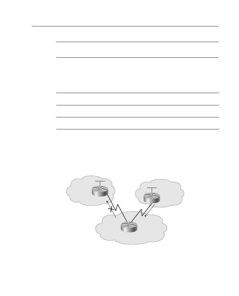
Supplement 5: BGP 62
NOTE
The set community command is used along with the neighbor route-map command to
apply the route map to updates.
The neighbor {ip-address | peer-group-name} send-community router configuration
command is used to specify that the BGP communities attribute should be sent to a BGP
neighbor. This command is detailed in Table A-27.
By default, the communities attribute is not sent to any neighbor (communities are stripped
in outgoing BGP updates).
In the example shown in Figure A-26, Router C is sending BGP updates to Router A, but it
does not want Router A to propagate these routes to Router B.
Figure A-26 Network for BGP Communities Example
The configuration for Router C in this example is provided in Example A-28. Router C sets
the community attribute in the BGP routes that it is advertising to Router A. The no-export
Table A-27
neighbor send-community Command Description
neighbor send-community
Command
Description
ip address
IP address of the BGP neighbor to which the communities
attribute will be sent.
peer-group-name
Name of a BGP peer group. (Peer groups are detailed in the
“Peer Groups” section, later in this supplement.)
AS 65000
AS 65500
10.10.10.2
B
A
C
172.30.0.0
10.10.20.2
192.168.1.0
AS 64520
10.10.10.1
10.10.20.1
172.30.0.0/16
172.30.0.0/16

63 Job Aids and Supplements
community attribute is used to indicate that Router A should not send the routes to its
external BGP peers.
In this example, Router C has one neighbor, 10.10.20.1 (Router A). When communicating
with Router A, the community attribute is sent, as specified by the neighbor send-
community command. The route map SETCOMM is used when sending routes to Router
A, to set the community attribute. Any route that matches access-list 1 will have the
community attribute set to no-export. Access list 1 permits any routes; therefore, all routes
will have the community attribute set to no-export.
In this example, Router A will receive all of Router C’s routes but will not pass them on to
Router B.
Using Communities Configuration
The ip community-list community-list-number permit | deny community-number global
configuration command is used to create a community list for BGP and to control access to
it, as described in Table A-28.
Some predefined well-known community numbers that can be used with the ip
community-list command are as follows:
•
no-export—Do not advertise to EBGP peers.
•
no-advertise—Do not advertise this route to any peer.
Example A-28
Configuration of Router C in Figure A-26
router bgp 65500
network 172.30.0.0
neighbor 10.10.20.1 remote-as 64520
neighbor 10.10.20.1 send-community
neighbor 10.10.20.1 route-map SETCOMM out
!
route-map SETCOMM permit 10
match ip address 1
set community no-export
!
access-list 1 permit 0.0.0.0 255.255.255.255
Table A-28
ip community-list Command Description
ip community-list
Command
Description
community-list-number
Community list number, in the range 1 to 99
community-number
Community number, configured by a set community command
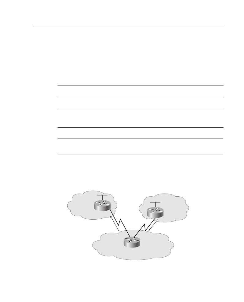
Supplement 5: BGP 64
•
local-AS—Do not send outside local AS.
•
internet—Advertise this route to the Internet community and any router that belongs
to it.
The match community community-list-number [exact] route map configuration command
is used to match a BGP community attribute to a value in a community list, as described in
Table A-29.
NOTE
The match community command appears in the documentation as the match community-
list command; however, only match community actually works on the routers.
In the example shown in Figure A-27, Router C is sending BGP updates to Router A. Router
A will set the weight of these routes based on the community value set by Router C.
Figure A-27 Network for BGP Communities Example Using Weight
Table A-29
match community Command Description
match community
Command
Description
community-list-number
Community list number, in the range 1 to 99, that will be used to
compare the community attribute.
exact
(Optional) Indicates that an exact match is required. All the
communities and only those communities in the community list must
be present in the community attribute.
AS 65000
AS 65500
10.10.10.2
B
A
C
172.30.0.0
10.10.20.2
192.168.1.0
AS 64520
10.10.10.1
10.10.20.1
172.30.0.0/16
172.30.0.0/16

65 Job Aids and Supplements
The configuration for Router C in Figure A-27 is shown in Example A-29. Router C has one
neighbor, 10.10.20.1 (Router A).
In this example, the community attribute will be sent to Router A, as specified by the
neighbor send-community command. The route map SETCOMM is used when sending
routes to Router A to set the community attribute. Any route that matches access-list 1 will
have community 100 added to the existing communities in the community attribute of the
route. In this example, access list 1 permits any routes; therefore, all routes will have 100
added to the list of communities. If the additive keyword in the set community command
was not set, 100 will replace any old community that already exits; because the keyword
additive is used, the 100 will be added to the list of communities that the route is part of.
The configuration for Router A in Figure A-27 is shown in Example A-30.
NOTE
Other router bgp configuration commands for Router A are not shown in Example A-30.
Example A-29
Configuration of Router C in Figure A-27
router bgp 65500
network 172.30.0.0
neighbor 10.10.20.1 remote-as 64520
neighbor 10.10.20.1 send-community
neighbor 10.10.20.1 route-map SETCOMM out
!
route-map SETCOMM permit 10
match ip address 1
set community 100 additive
!
access-list 1 permit 0.0.0.0 255.255.255.255
Example A-30
Configuration of Router A in Figure A-27
router bgp 64520
neighbor 10.10.20.2 remote-as 65500
neighbor 10.10.20.2 route-map CHKCOMM in
!
route-map CHKCOMM permit 10
match community 1
set weight 20
route-map CHKCOMM permit 20
match community 2
!
ip community-list 1 permit 100
ip community-list 2 permit internet
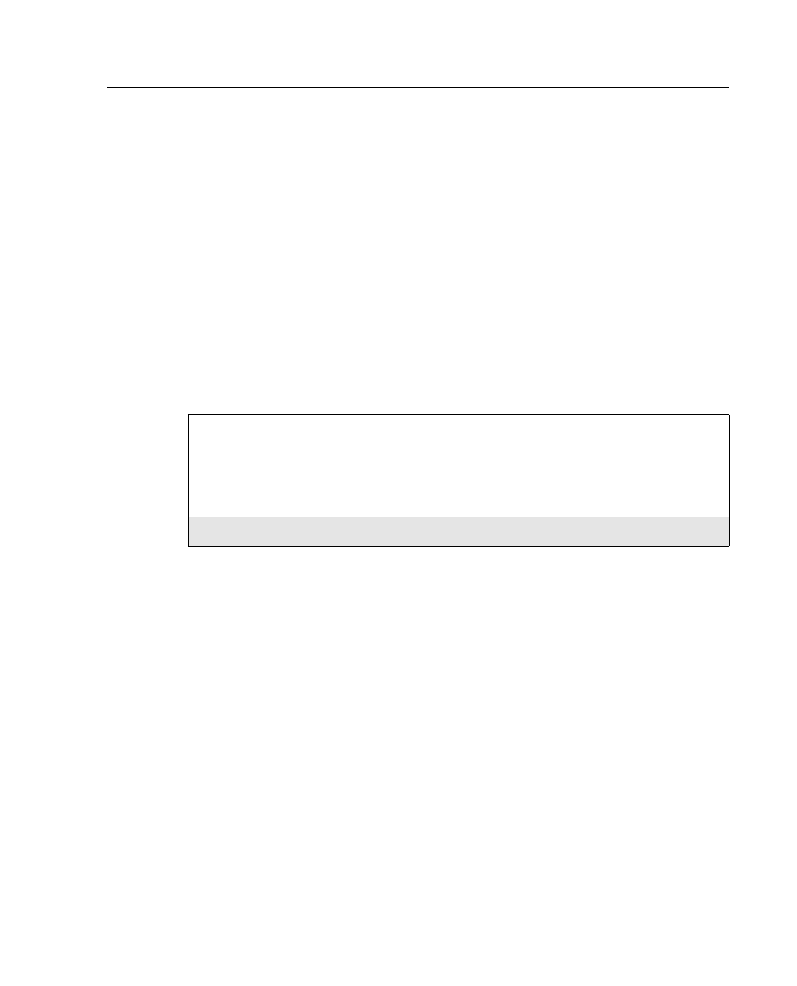
Supplement 5: BGP 66
In this example, Router A has a neighbor, 10.10.20.2 (Router C). The route map
CHKCOMM is used when receiving routes from Router C to check the community
attribute. Any route whose community attribute matches community list 1 will have its
weight attribute set to 20. Community list 1 permits routes with a community attribute of
100; therefore, all routes from Router C (which all have 100 in their list of communities)
will have their weight set to 20.
In this example, any route that did not match community list 1 would be checked against
community list 2. Any route matching community list 2 would be permitted but would not
have any of its attributes changed. Community list 2 specifies the internet keyword, which
means all routes.
The example output shown in Example A-31 is from Router A in Figure A-27. The output
shows the details about the route 172.30.0.0 from Router C, including that its community
attribute is 100 and its weight attribute is now 20.
Peer Groups
This section discusses peer groups and how to configure them.
In BGP, many neighbors often are configured with the same update policies (that is, the
same outbound route maps, distribute lists, filter lists, update source, and so on). On Cisco
routers, neighbors with the same update policies can be grouped into peer groups to
simplify configuration and, more importantly, to make updating more efficient. When you
have many peers, this approach is highly recommended.
A BGP peer group is a group of BGP neighbors with the same update policies. Instead of
separately defining the same policies for each neighbor, a peer group can be defined with
these policies assigned to the peer group. Individual neighbors are then made members of
the peer group.
Members of the peer group inherit all the configuration options of the peer group. Members
can also be configured to override these options if these options do not affect outbound
updates; in other words, only options that affect the inbound updates can be overridden.
Example A-31
Output from Router A in Figure A-27
RtrA #show ip bgp 172.30.0.0/16
BGP routing table entry for 172.30.0.0/16, version 2
Paths: (1 available, best #1)
Advertised to non peer-group peers:
10.10.10.2
65500
10.10.20.2 from 10.10.20.2 (172.30.0.1)
Origin IGP, metric 0, localpref 100, weight 20, valid, external, best, ref 2
Community: 100

67 Job Aids and Supplements
Peer groups are useful to simplify configurations when many neighbors have the same
policy. They are also more efficient because updates are generated only once per peer group
rather than once for each neighbor.
The peer group name is local only to the router it is configured on; it is not passed to any
other router.
Peer Group Configuration
The neighbor peer-group-name peer-group router configuration command is used to
create a BGP peer group. The peer-group-name is the name of the BGP peer group to be
created.
Another syntax of the neighbor peer-group command is used to assign neighbors as
part of the group; use the neighbor ip-address peer-group peer-group-name router
configuration command. The details of this command are shown in Table A-30.
The clear ip bgp peer-group peer-group-name EXEC command is used to clear the BGP
connections for all members of a BGP peer group. The peer-group-name is the name of the
BGP peer group for which connections are to be cleared.
NOTE
The Cisco documentation says that the clear ip bgp peer-group command is used to
remove all the members of a BGP peer group; however, it actually clears the connections.
Peer Group Example
In the example shown in Figure A-28, Router A has two internal neighbors, routers D and
E, and two external neighbors, routers B and C. The routing policies for routers D and E are
the same, and the routing policies for routers B and C are the same.
Table A-30
neighbor peer-group Command Description
neighbor peer-group
Command
Description
ip-address
IP address of the neighbor that is to be assigned as a member of the
peer group
peer-group-name
Name of the BGP peer group
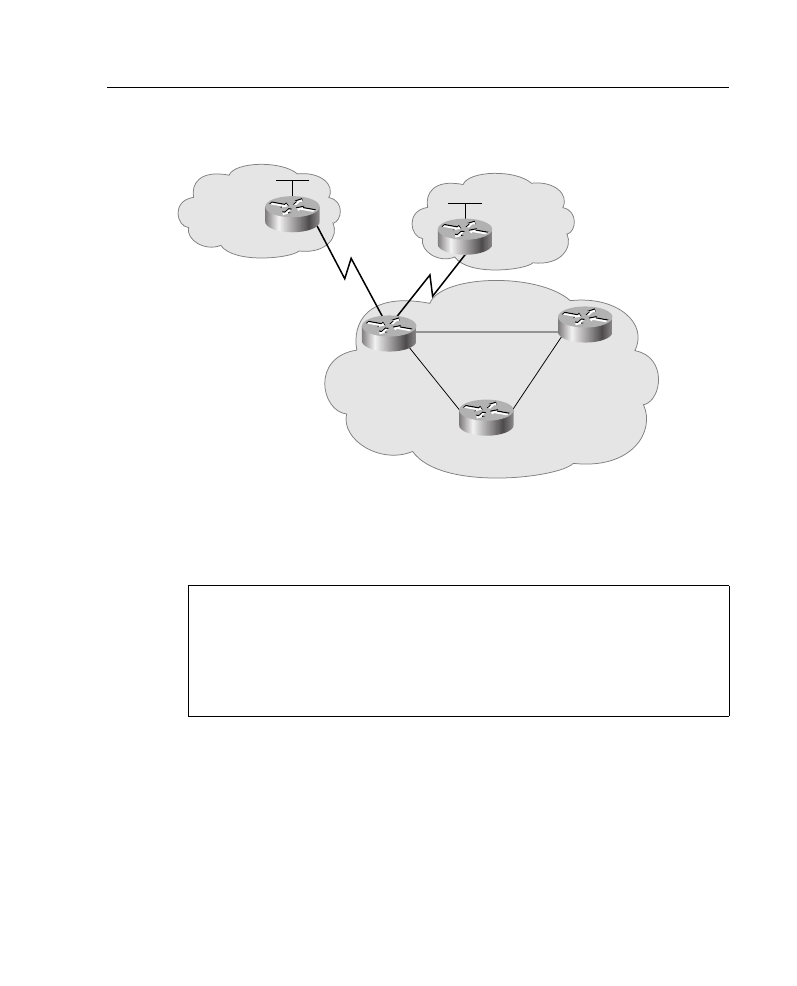
Supplement 5: BGP 68
Figure A-28 Network for BGP Peer Group Example
Router A is configured with two peer groups, one for internal neighbors and one for external
neighbors, rather than individual neighbor configurations. Example A-32 shows part of the
configuration for Router A, for the internal neighbors.
This configuration creates a peer group called INTERNALMAP. All members of this peer
group are in AS 64520. A prefix list called PREINTIN will be applied to all routes from
members of this peer group, and a prefix list called PREINTOUT will be applied to all
routes going to members of this peer group. A route map called SETINTERNAL will be
applied to all routes going to members of this peer group.
Router E (192.168.2.2) and Router D (192.168.1.2) are members of the peer group
INTERNALMAP.
Example A-32
Router A in Figure A-28 Configuration for Internal Neighbors
router bgp 64520
neighbor INTERNALMAP peer-group
neighbor INTERNALMAP remote-as 64520
neighbor INTERNALMAP prefix-list PREINTIN in
neighbor INTERNALMAP prefix-list PREINTOUT out
neighbor INTERNALMAP route-map SETINTERNAL out
neighbor 192.168.2.2 peer-group INTERNALMAP
neighbor 192.168.1.2 peer-group INTERNALMAP
neighbor 192.168.2.2 prefix-list JUST2 in
AS 65000
AS 65500
10.10.10.2
B
A
E
D
C
172.30.0.0
10.10.20.2
10.10.20.1
192.168.2.1
192.168.2.2
192.168.3.1
192.168.3.2
192.168.1.2
192.168.1.1
AS 64520
10.10.10.1

69 Job Aids and Supplements
A prefix list called JUST2 will be applied to all routes from Router E (192.168.2.2). Recall
that you can override only peer group options that affect inbound updates.
NOTE
Router bgp configuration commands for Router A not related to peer groups are not shown
in Example A-32.
Example A-33 shows part of the configuration for Router A in Figure A-28, for the external
neighbors.
This configuration creates a peer group called EXTERNALMAP. A prefix list called
PREEXTIN will be applied to all routes from members of this peer group, and a prefix list
called PREEXTOUT will be applied to all routes going to members of this peer group. A
route map called SETEXTERNAL will be applied to all routes going to members of this
peer group.
Router B (10.10.10.2) is in AS 65000 and is a member of the peer group EXTERNALMAP.
Router C (10.10.20.2) is in AS 65500 and is a member of the peer group EXTERNALMAP.
A prefix list called JUSTEXT2 will be applied to all routes from Router B (10.10.10.2).
Recall that you can override only peer group options that affect inbound updates.
NOTE
Router bgp configuration commands for Router A not related to peer groups are not shown
in Example A-33.
Example A-33
Router A in Figure A-28 Configuration for External Neighbors
router bgp 64520
neighbor EXTERNALMAP peer-group
neighbor EXTERNALMAP prefix-list PREEXTIN in
neighbor EXTERNALMAP prefix-list PREEXTOUT out
neighbor EXTERNALMAP route-map SETEXTERNAL out
neighbor 10.10.10.2 remote-as 65000
neighbor 10.10.10.2 peer-group EXTERNALMAP
neighbor 10.10.10.2 prefix-list JUSTEXT2 in
neighbor 10.10.20.2 remote-as 65500
neighbor 10.10.20.2 peer-group EXTERNALMAP
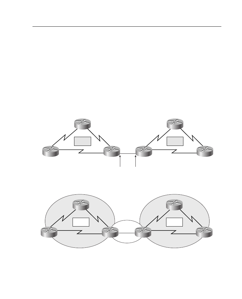
Supplement 6: Route Optimization 70
Supplement 6: Route Optimization
This supplement reviews the following topics:
•
Examples of redistribution in a nonredundant configuration
•
Miscellaneous redistribution configuration examples
Examples of Redistribution in a Nonredundant Configuration
This section includes configuration and show command output examples that result from
configuring the network shown in Figure A-29. The addresses for this configuration are also
shown in Figure A-29; protocols for the example are shown in Figure A-30.
Figure A-29 Addressing for Redistribution Configuration Example
Figure A-30 Example Nonredundant Redistribution Configuration
P1R2
P1R1
P2R3
P2R1
P1R3
P2R2
Pod 1
Pod 2
10.1.1.1/24
10.1.2.1/24
10.2.1.1/24
10.2.2.1/24
10.1.1.2/24
10.1.3.1/24
10.2.3.1/24
10.1.2.2/24 10.2.1.2/24
10.2.2.2/24
10.1.3.2/24
10.2.3.2/24
10.64.0.1/24
10.64.0.2/24
P1R2
P1R1
P2R3
P2R1
E0
E0
P1R3
P2R2
OSPF
EIGRP
EIGRP
Pod 1
Pod 2

71 Job Aids and Supplements
Example of Redistribution Between EIGRP and OSPF
Example A-34 shows the configuration output for P1R3, an ASBR supporting EIGRP and
OSPF.
Example A-34
ASBR in Figures A-29 and A-30, Redistributing Between EIGRP and OSPF
P1R3#show run
Building configuration...
Current configuration:
!
version 11.2
hostname P1R3
!
enable password san-fran
!
no ip domain-lookup
ipx routing 0000.0c01.3333
ipx maximum-paths 2
!
interface Loopback0
no ip address
ipx network 1013
!
interface Ethernet0
ip address 10.64.0.1 255.255.255.0
!
interface Serial0
ip address 10.1.3.2 255.255.255.0
bandwidth 64
ipx input-sap-filter 1000
ipx network 1003
!
interface Serial1
ip address 10.1.2.2 255.255.255.0
ipx input-sap-filter 1000
ipx network 1002
clockrate 56000
<Output Omitted>
!
router eigrp 200
redistribute ospf 300 metric 10000 100 255 1 1500
passive-interface Ethernet0
network 10.0.0.0
!
router ospf 300
redistribute eigrp 200 subnets
network 10.64.0.0 0.0.255.255 area 0
!
no ip classless

Supplement 6: Route Optimization 72
In Example A-34, EIGRP in AS 200 is configured for all interfaces in network 10.0.0.0. The
passive-interface command is used to disable EIGRP on the ethernet (because OSPF will
be running there). Routes from OSPF are redistributed into EIGRP with the redistribute
command, using the defined metrics. OSPF is configured to run on the ethernet 0 interface,
in area 0. Routes from EIGRP are redistributed into EIGRP; the subnets keyword is
included so that subnetted routes (in this case, subnets of network 10.0.0.0) will be
redistributed. If this keyword were omitted, no routes would be redistributed from OSPF to
EIGRP in this example.
Example A-35 shows outputs verifying that external routes are learned by OSPF and
EIGRP, respectively, on an ASBR.
line con 0
exec-timeout 20 0
password cisco
!
line aux 0
line vty 0 4
password cisco
!
end
Example A-35
OSPF and EIGRP Topology Databases of P1R3 in Figures A-29 and A-30
P1R3#show ip ospf database
OSPF Router with ID (10.64.0.1) (Process ID 300)
Router Link States (Area 0)
Link ID ADV Router Age Seq# Checksum Link count
10.64.0.1 10.64.0.1 280 0x80000005 0x767F 1
10.64.0.2 10.64.0.2 274 0x80000004 0x767D 1
Net Link States (Area 0)
Link ID ADV Router Age Seq# Checksum
10.64.0.2 10.64.0.2 274 0x80000002 0x7791
Type-5 AS External Link States
Link ID ADV Router Age Seq# Checksum Tag
10.1.1.0 10.64.0.1 202 0x80000002 0xE95E 0
10.1.2.0 10.64.0.1 202 0x80000002 0xDE68 0
10.1.3.0 10.64.0.1 202 0x80000002 0xD372 0
10.2.1.0 10.64.0.2 1686 0x80000001 0xD96D 0
10.2.2.0 10.64.0.2 1686 0x80000001 0xCE77 0
Example A-34
ASBR in Figures A-29 and A-30, Redistributing Between EIGRP and OSPF (Continued)
continues

73 Job Aids and Supplements
In Example A-35, you can see from the show ip ospf database command output that P1R3
learns external routes (type 5 LSAs) in OSPF. Note that subnetted networks are included.
EIGRP also learns external routes, shown as redistributed routes in the show ip eigrp
topology command output.
Miscellaneous Redistribution Configuration Examples
This section presents examples of one-way redistribution.
IGRP Redistribution Example
Cisco IOS software supports multiple IGRP autonomous systems. Each autonomous
system maintains its own routing database. You can redistribute routing information among
these routing databases. Table A-31 describes some of the commands seen in Example
A-36. Refer to Figure A-31 for the topology used in Example A-36.
10.2.3.0 10.64.0.2 1686 0x80000001 0xC381 0
10.64.0.0 10.64.0.1 204 0x80000002 0xFD0C 0
10.64.0.0 10.64.0.2 1688 0x80000001 0xF910 0
P1R3#
P1R3#show ip eigrp topology
IP-EIGRP Topology Table for process 200
Codes: P - Passive, A - Active, U - Update, Q - Query, R - Reply,
r - Reply status
P 10.1.3.0/24, 1 successors, FD is 40512000
via Connected, Serial0
via 10.1.2.1 (3193856/2681856), Serial1
P 10.2.1.0/24, 1 successors, FD is 281600
via Redistributed (281600/0)
P 10.1.2.0/24, 1 successors, FD is 2169856
via Connected, Serial
P 10.2.2.0/24, 1 successors, FD is 281600
via Redistributed (281600/0)
P 10.1.1.0/24, 1 successors, FD is 2681856
via 10.1.2.1 (2681856/2169856), Serial1
P 10.2.3.0/24, 1 successors, FD is 281600
via Redistributed (281600/0)
P 10.64.0.0/24, 1 successors, FD is 281600
via Connected, Ethernet0
Example A-35
OSPF and EIGRP Topology Databases of P1R3 in Figures A-29 and A-30 (Continued)
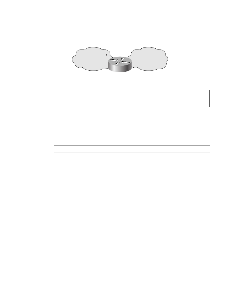
Supplement 6: Route Optimization 74
Figure A-31 Figure A-31 IGRP Redistribution Configuration Example
In Example A-36, only routing updates from the 192.168.7.0 network are redistributed into
autonomous system 71. Updates from other networks are denied.
RIP/OSPF Redistribution Example
In Example A-37 and Figure A-32, there is an additional path connecting the RIP clouds.
These paths, or “back doors,” frequently exist, allowing the potential for feedback loops.
You can use access lists to determine the routes that are advertised and accepted by each
router.
Example A-36
Routes Redistributed from AS 109 into AS 71 in Figure A-31
router igrp 71
redistribute igrp 109
distribute-list 3 out igrp 109
access-list 3 permit 192.168.7.0 0.0.0.255
Table A-31
Redistribution Commands in Example A-36
Command
Description
redistribute igrp 109
Redistributes routes from IGRP 109 into IGRP 71.
distribute list 3 out igrp
109
Uses access list 3 to define which routes will be redistributed from
IGRP 109 into IGRP 71.
3
Redistributes per access list 3.
out
Applies the access list to outgoing routing updates.
igrp 109
Identifies the IGRP routing process to filter.
access-list 3 permit
192.168.7.0 0.0.0.255
Permits routes from only network 192.168.7.0.
AS 109
192.168.7.0
AS 71
10.0.0.0
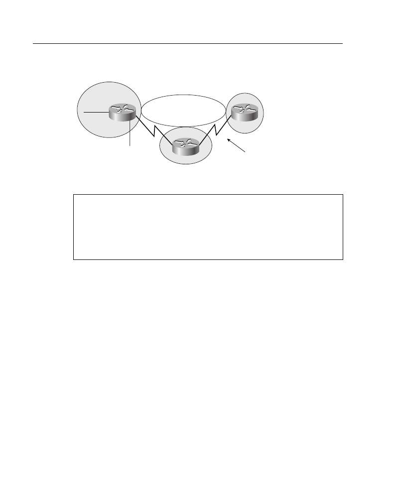
75 Job Aids and Supplements
Figure A-32 Blocking Paths to Avoid Looping
For example, access list 11 in the configuration file for Router R1 allows OSPF to
redistribute information learned from RIP only for networks 172.16.8.0 through
172.16.15.0. These commands prevent Router R1 from advertising networks in other RIP
domains onto the OSPF backbone, thereby preventing other boundary routers from using
false information and forming a loop. You would configure similar access lists on R2
and R3.
Redistribution Example Using Default Metric
In Figure A-33 and Example A-38, the router is redistributing IP RIP and EIGRP routes.
The 192.168.5.0 network is redistributed to the IP RIP network with a metric of three hops.
EIGRP in autonomous system 300 learns routes from IP RIP.
Example A-37
Avoiding Loops While Redistributing on Router R1 in Figure A-32
hostname R1
!
router ospf 109
network 172.16.62.0 0.0.0.255 area 0
network 172.16.63.0 0.0.0.255 area 0
redistribute rip subnets metric-type 1 metric 20
distribute-list 11 out rip
access-list 11 permit 172.16.8.0 0.0.7.255
172.16.8.1
OSPF Area 0
“Back door” creates
potential loop
R1
R2
172.16.9.1
R3
RIP
RIP
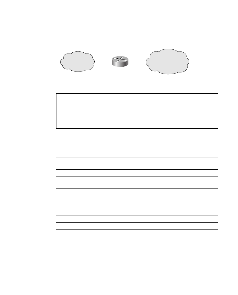
Supplement 6: Route Optimization 76
Figure A-33 Redistributing RIP and EIGRP
Table A-32 describes some of the commands seen in Example A-38.
Redistribution Example Using Filtering
Figure A-34 and Example A-39 provide an example of a redistribution filtering.
Example A-38
Redistribution Using Default Metric in Figure A-33
router rip
network 172.16.0.0
redistribute eigrp 300
default-metric 3
router eigrp 300
network 192.168.5.0
redistribute rip
default-metric 56 2000 255 1 1500
Table A-32
Redistribution Commands in Example A-38
Command
Description
redistribute eigrp
300
Enables redistribution of routes learned from EIGRP autonomous system
300 into the IP RIP network.
default-metric 3
Specifies that EIGRP-learned routes are three hops away.
redistribute rip
Enables redistribution of routes learned from the IP RIP network into EIGRP
autonomous system 300.
default-metric 56
2000 255 1 1500
Indicates that the RIP-derived network is being redistributed with the
following EIGRP metric values:
56
Bandwidth is 56 kbps.
2000
Delay is 2000 tens of microseconds.
255
Reliability is 100 percent (255 of 255).
1
Loading is less than 1 percent (1 of 255).
1500
MTU is 1500 bytes.
Autonomous
system 300
EIGRP
192.168.5.0
RIP
172.16.0.0
A

77 Job Aids and Supplements
Figure A-34 Redistribution Using Filtering and Default Metric
Table A-33 describes some of the commands seen in Example A-39.
Redistribution Example Using Filtering and Default Metric
Figure A-35 and Example A-40 provide an example of a redistribution filtering and default
metric.
Example A-39
R1 in Figure A-34 Hides Network 10.0.0.0 Using Redistribution Filtering
hostname R1
!
router rip
network 192.168.5.0
redistribute eigrp 1
default-metric 3
distribute-list 7 out eigrp 1
!
router eigrp 1
network 172.16.0.0
redistribute rip
default-metric 56 2000 255 1 1500
!
access-list 7 deny 10.0.0.0 0.255.255.255
access-list 7 permit 0.0.0.0 255.255.255.255
Table A-33
R6 Redistribution Filtering Commands in Example A-39
Command
Description
redistribute eigrp 1
Enables routes learned from EIGRP autonomous system 1 to be
redistributed into IP RIP.
default-metric 3
Specifies that all routes learned from EIGRP will be advertised
by RIP as reachable in three hops.
distribute-list 7 out eigrp 1
Defines that routes defined by access-list 7 leaving the EIGRP
process will be filtered before being given to the RIP process.
EIGRP 1
172.16.0.0
EIGRP 1
10.0.0.0
RIP
192.168.5.0
R2
R1

Supplement 6: Route Optimization 78
Figure A-35 Figure A-35 Redistribution Filtering and Default Metric
Table A-34 describes some of the commands seen in Example A-40.
Example A-40
Redistributing RIP and IGRP
router rip
network 192.168.8.0
network 172.16.0.0
redistribute igrp 109
default-metric 4
distribute-list 11 out igrp 109
!
router igrp 109
network 192.168.7.0
redistribute rip
default-metric 10000 100 255 1 1500
distribute-list 10 out rip
access-list 10 permit 172.16.0.0 0.0.255.255
access-list 11 permit 192.168.7.0 0.0.0.255
Table A-34
Redistribution and Route Filtering Commands in Example A-40
Command
Description
redistribute igrp 109
Redistributes IGRP routes into RIP.
default-metric 4
Sets the metric for IGRP-derived routes to four hops.
redistribute rip
Redistributes RIP routes into IGRP.
default-metric
Sets the metric for IGRP for all redistributed routes.
10000
Sets the minimum bandwidth of the route to 10,000 kbps.
100
Sets the delay to 100 tens of microseconds.
255
Sets the reliability, in this case, to the maximum.
1
Sets the loading to 1.
1500
Sets the MTU to 1500 bytes.
distribute list 10 out
rip
Uses access list 10 to limit updates going out of RIP into IGRP.
192.168.8.0
172.16.0.0
RIP
AS 109
192.168.7.0
Wyszukiwarka
Podobne podstrony:
więcej podobnych podstron