
EdgeCAM Manufacture – User Guide
EdgeCAM Manufacture – User Guide
Contents
EdgeCAM Manufacture Mode.....................................................................................1
E
NTERING
M
ANUFACTURE
M
ODE
........................................................................3
S
ELECTING
T
OOLS
............................................................................................14
C
HECKING THE
P
ART
........................................................................................34
M
OVING THE
T
OOL
...........................................................................................37
S
ELECTING A
C
YCLE
.........................................................................................47
F
INISHING A
C
OMMAND
.....................................................................................47
U
SING
C
UTTER
C
OMPENSATION
........................................................................48
D
ISPLAYING
T
OOLPATHS
...................................................................................54
Editing Instructions in the Browser.........................................................................57
E
DITING
I
NSTRUCTIONS
.....................................................................................57
C
OMBINING
C
OMPONENTS AND
S
EQUENCES
......................................................59
I
NSERTING
S
EQUENCES
....................................................................................62
M
ERGING
S
EQUENCES
......................................................................................63
R
E
-
ORDERING THE
M
ACHINING
I
NSTRUCTIONS IN A
S
EQUENCE
...........................64
M
ERGING
H
OLE
C
YCLES
...................................................................................71
U
SING
I
NSTRUCTIONS
M
ENU
C
OMMANDS
...........................................................75
Editing the Toolpath..................................................................................................79
D
ELETING A
S
ECTION OF A
T
OOLPATH
...............................................................80
E
DITING A
S
ECTION OF A
T
OOLPATH
..................................................................80
S
PLITTING A
T
OOLPATH
....................................................................................80
T
RANSFORMING THE
T
OOLPATHS
......................................................................81
Generating CNC Code...............................................................................................87
P
ASSING
J
OB
D
ATA TO THE
NC F
ILE
.................................................................89
A
BOUT
CNC F
ILENAMES
...................................................................................89
C
ODE
G
ENERATOR
C
OMMANDS
........................................................................90
E
DITING THE
CNC C
ODE
..................................................................................92
i

EdgeCAM Manufacture - User Guide
EdgeCAM Manufacture Mode
E
NTERING
M
ANUFACTURE
M
ODE
.......................................................................3
Browsing the Instruction List .......................................................................4
The Context Menu in the Instruction Browser .........................................................5
About Machining Sequences ......................................................................6
Defining a Machining Sequence .................................................................7
About the Initial CPL....................................................................................8
Passing Job Data to the NC File ...............................................................10
Selecting an Existing Machining Sequence ..............................................11
Building the Instruction List .......................................................................11
Changing the Machine Parameters...........................................................12
Conversion of Arcs to Lines ......................................................................13
S
ELECTING
T
OOLS
..........................................................................................14
Selecting from the ToolStore.....................................................................14
Selecting from the Tool Library .................................................................15
Defining New Tools Interactively ...............................................................16
Selecting the Wire .................................................................................................17
Milling Cutter Parameters..........................................................................18
Turning Tool Parameters...........................................................................19
Specifying Insert Parameters ................................................................................20
Specifying Turret Parameters................................................................................22
Selecting a New Tool Datum.....................................................................23
Saving Tool Graphics ................................................................................24
Displaying the Tool....................................................................................24
Displaying the Tool Holder ........................................................................25
Setting Feeds and Speeds for Milling and Turning Tools .........................26
Setting Speeds and Feeds Manually.....................................................................26
Setting Speeds and Feeds Automatically..............................................................26
Viewing the Current Technology Values ...................................................28
Material Technology Table ....................................................................................29
Tool Technology Table..........................................................................................29
Defining New Material Technology Tables ............................................................29
Selecting a Safe Distance for the Tool......................................................30
Selecting a Safe Distance for the Turning Tool ........................................31
U
SING
M
ISCELLANEOUS
(M-) F
UNCTIONS
........................................................32
Checking the Miscellaneous Functions .................................................................33
C
HECKING THE
P
ART
.......................................................................................34
Verifying the Machining Parameters .........................................................34
Viewing the Machine Datum Co-ordinates................................................35
M
OVING THE
T
OOL
..........................................................................................37
Moving at the Rapid Rate (Milling and Turning environment)...................37
Moving the Wire at the Rapid Rate .......................................................................38
Moving at the Feed Rate ...........................................................................38
Editing Co-ordinates of Rapid and Feed Moves .......................................39
Moving the Tool in an Arc at the Feedrate ................................................41
Moving the Tool around a Co-ordinate Axis..............................................41
Moving the Tool to the Toolchange Position .............................................41
Moving the Tool to the Home Position ......................................................42
Moving to the Initial Plane .........................................................................43
Freehand Milling ........................................................................................43
Exact Tool Positioning in Turning..............................................................44
Moving Relative to an Entity......................................................................45
Moving Constrained by Entities.................................................................46
Moving Relative to Two Entities ................................................................46
1

Manufacturing Basics
S
ELECTING A
C
YCLE
........................................................................................47
F
INISHING A
C
OMMAND
....................................................................................47
U
SING
C
UTTER
C
OMPENSATION
.......................................................................48
Using Cutter Compensation in Milling Cycles ...........................................48
Using Wire Compensation.........................................................................49
Using No Compensation ...........................................................................50
Using Controller Compensation ................................................................50
Using Pathtrace Compensation.................................................................51
Using Cutter Compensation in Turning Cycles .........................................52
D
ISPLAYING
T
OOLPATHS
.................................................................................54
Controlling the Toolpath Mode ..................................................................54
Simulating Tool Movement........................................................................54
Displaying Solid Models ............................................................................55
2
EdgeCAM Manufacture - User Guide
Entering Manufacture Mode
EdgeCAM starts up in Design mode, as it assumes that you want to begin by
creating a part. If you have already created a part, or have loaded an existing
part, you will now want to start the machining process.
To use the EdgeCAM system, you should be experienced in CAD/CAM
methods and the appropriate equipment and terminology. You also need to
have some experience of the Microsoft™ Windows NT™ graphical user
environments.
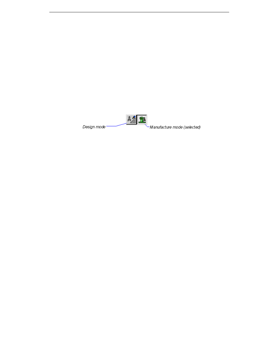
Most of the commands you require are not present in Design mode (to make
the number of commands available to you more manageable). To access the
commands for machining a part, you must enter the Manufacture mode. Select
Manufacture (Options menu) or press the Manufacture button to switch into
Manufacture mode.
If you need to switch back into Design mode at any time, click on the Design
button or select Design (Options menu).
If this is the first time you have entered Manufacture mode since starting
EdgeCAM, you are prompted for details on what type of machining you want to
use. This information defines a new “machining sequence” or machining
worksession. You also specify which Code Generator file you want to use. A
Code Generator provides appropriate manufacturing commands and contains
the data on converting an EdgeCAM machining sequence into CNC code for a
specific machine tool type.
You may enter Manufacture mode with a new executable file (for example, a
PDI) or a new Code Generator file. If you do, you are prompted to enter the
text for the machine-specific commands that appear under the M-Functions
menu.
About Creating Wire Toolpaths
Before you try to create wire toolpaths, you should already have created a
Wire Profile. Whichever method you used to create the profile, simply select
the command Machine Design (Cycles menu). This command uses
whatever information is stored in the profile to generate the appropriate
toolpaths. Also see Creating the Design Intent.
3
Manufacturing Basics
Browsing the Instruction List
The Instruction List is, simply, the list of all machining commands for the
current part. Each time a new machining command is used on the part, it is
added to the bottom of the list of the current machining sequence.
Commands that cannot be converted into CNC code (for example, viewing
and editing commands) do not appear on the list.
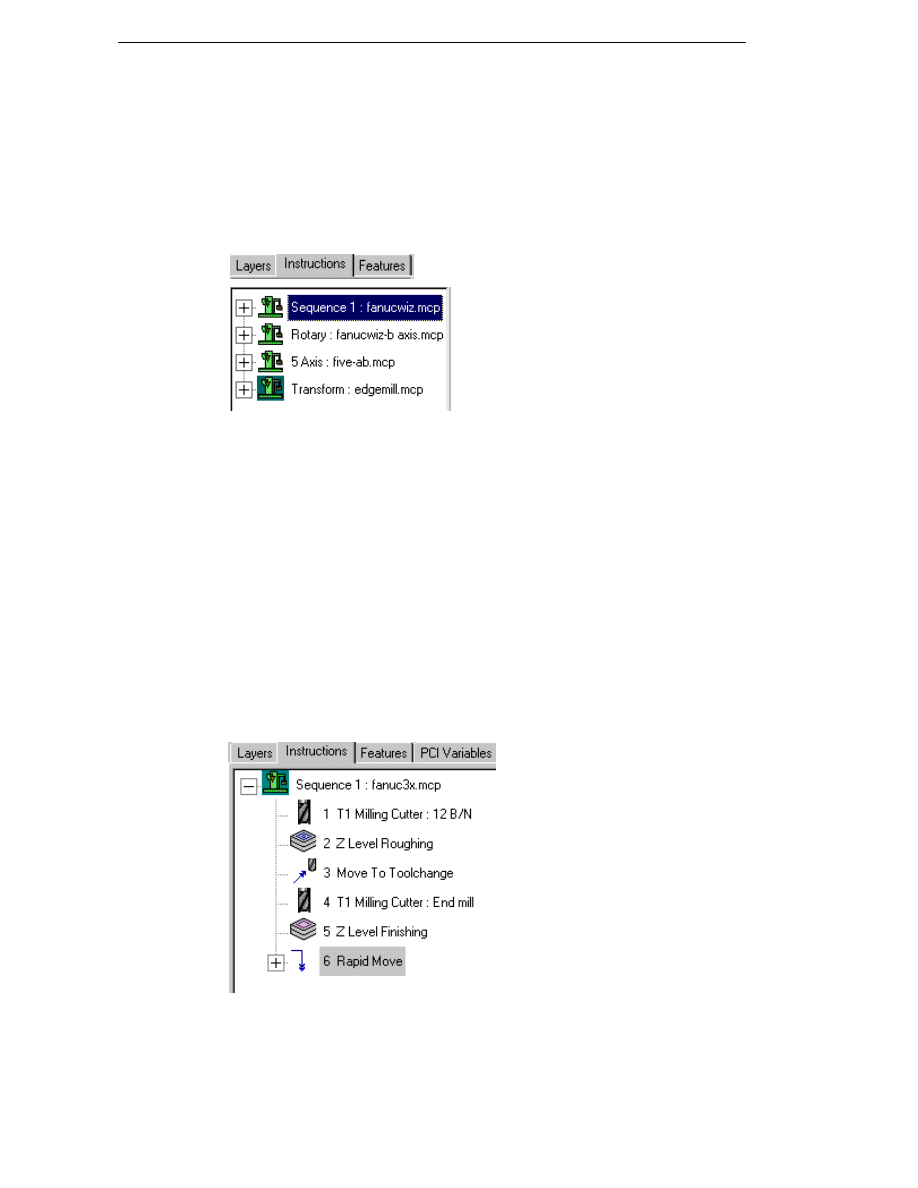
The browser on the left of the screen shows all machining sequences and
instructions associated with the current part.
You can also view the EdgeCAM Instruction list associated with a job from
within the Job Manager or the web-based Job Reports. If an associated
instruction list exists for a particular job, the instructions will be displayed on
the Instructions tab of the Job Manager or through a link on the job reports
page.
The icon for the current machining sequence is shown with a green
background.Note that the machine sequence description is followed by the
code generator file (‘Machine Tool’ in dialogs defining the sequence) used by
the sequence. ‘Sequence 1’ is used by default if you do not specify a
description.
By default, as the mouse is moved over an instruction in the browser window,
the relevant toolpath is automatically highlighted in the graphics area. Uncheck
the Highlight Instructions option on the Toolpaths tab of the Preferences
(Options menu) dialog to disable this functionality.
Clicking on a plus sign expands the view to show all instructions under that
machining sequence, including toolchange descriptions with turret position.
To collapse part of the view, click on the minus sign.
You can use the mouse to drag instructions to a new position in the list if
necessary. You can also copy instructions to a new position in the list by
holding down the 'Ctrl' key while dragging the instructions.
4
EdgeCAM Manufacture - User Guide
By default, the instructions in the Browser window are numbered as this can
be useful when a part has a large number of similar instructions. To display
the instructions without numbers, please ensure that the Number
Instructions option on the Toolpath tab of the Preferences (Options menu)
dialog is unchecked.
Displaying the individual co-ordinates in feed and rapid moves can slow down
EdgeCAM when working with a part containing a large number of
instructions. Uncheck the Display Co-ordinates option on the Toolpaths tab
of the Preferences (Options menu) dialog if you do not wish to display the co-
ordinates.
Note that you may edit instructions within an operation, but this will break the
operation down into its component instructions.
You can also group instructions together as operations using Operation
(Instructions menu). This means that when editing the instruction list you
could edit individual commands or entire operations. Do not confuse these
with the integrated machining commands provided under the Operations
menu.
The Context Menu in the Instruction Browser
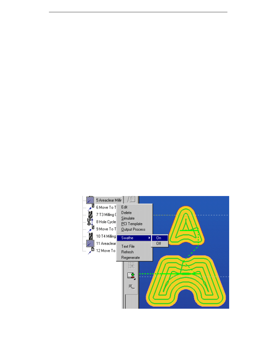
A right-hand mouse click on an instruction opens the context menu with the
options Edit, Delete, Simulate, PCI Template, Swathe, Text File, Refresh
and Regenerate.
The first three options are self-explanatory. The Text File option allows you to
export the contents of the sequence to a text file for subsequent printing.
Different levels of information can be exported to the text file. The PCI
Template command allows you to generate a PCI from selected instructions
in the browser If you make changes to the instruction list, the display is not
updated. In this case, use the Refresh option to ensure that the instruction list
is displayed correctly in the browser window. The Regenerate option will
regenerate the sequence from the selected instructions.
The Swathe option (supported in both milling and turning) allows you to
activate/deactivate the Swathe mode in GLView.
Note that this functionality will only display a planar 'slice' at each level of cut.
5

Manufacturing Basics
The Output Process option is used to select one or more EdgeCAM
instructions to be passed to Strategy Manager. EdgeCAM Strategy Manager
is a product introducing rules based machining to the Solid Machinist user that
combines logic and flow chart methodology to capture working practices and
define a machining strategy, which can then be applied to EdgeCAM hole
cycles and operations in the first development phase in version 7.00.
EdgeCAM Strategy Manager is a separate licensed application. Please
contact your EdgeCAM reseller for further information on Strategy Manager.
About Machining Sequences
A machining sequence is a set of machining information for an EdgeCAM
part. Depending on the environment, it specifies the:
machine tool (the Code Generator to be used to provide machining
commands and to create CNC code from the instruction list)
machine datum for the machine tool
axis system being used
turret configurations
machine tool specific functions available (added to the M-Functions
menu)
units to be used in the CNC output
sequential list of machining instructions and/or operations.
If a part has been saved, the default sequence is the sequence in use when
the part was saved. This sequence is used for the part at the start of a new
Manufacture session.
A new sequence can be defined at any time in Manufacture using the
command New Sequence (File menu).
An existing sequence can be selected using the command Select Sequence
(File menu).
Parts can contain multiple sequences, for example two milling operations on
the same model. Also, more than one discipline (mill, inspection, turning, and
so on) can be used with the same model.
If you have to physically move the workpiece from one setup to another, you
should consider using separate sequences, as the output will be for machine
tools used in that setup.
If the part is complex, the redraw time may get quite long, so you may want to
break it down. However, you must then merge the files together with an editor
(the EdgeCAM Editor is recommended).
6
EdgeCAM Manufacture - User Guide
Defining a Machining Sequence
When you enter the Manufacture module for the first time, or as a result of
selecting the command New Sequence (File menu), you are asked to create a
new machining sequence.
The parameters for the sequence are:
Billet - (Turning environment only) Check this box to define the geometry of
the billet (bar stock).After you click on OK to dismiss the sequence parameters,
you can digitise the entities that define the initial material profile or billet.
Alternatively you can specify two opposite corners of the billet using the
mouse or by inputting the actual co-ordinates using the
button. The
first point is the outer corner of the billet:
Mirror View - (Turning environment only) Check this box to create a mirrored
profile about the Z axis that you can use for Four Axis cycles. EdgeCAM only
needs the upper side of the turned profile to be drawn. After you click on OK to
dismiss the sequence parameters, you can digitise the profile that you
want to mirror. Perform a Finish and the mirrored profile is created.
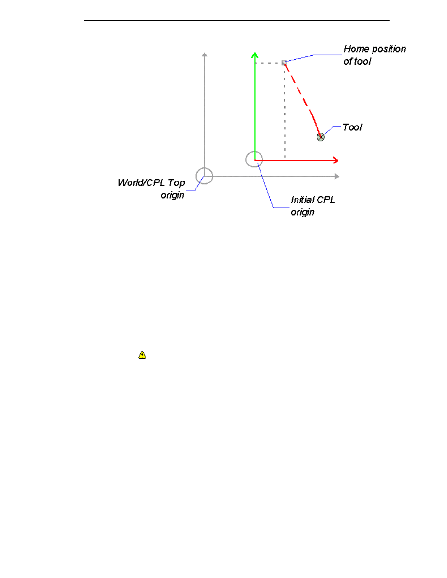
Machine Datum – (Milling and turning environment only) Specifies the
effective machine origin. This defaults to CPL Top (in milling) or the Initial
CPL (in turning), but you may select any desired location.
You may specify a point on the graphics screen using co-ordinates or a digitise.
A CPL will be generated at this location, with the same orientation as the Initial
CPL.
To help visualise the Machine Datum, you can display the Primary and
Secondary axes by selecting the Machine Datum box in the Drawing,
Configure (View menu) command.
Sequence Name – Type in a (descriptive) name for the new machining
sequence (eg. 'OP1'). Please note that each machining sequence must have a
unique name.
Job Name – Select a job be entering the appropriate name or use the Browse
button to call up the Job Manager and select a job from the list. Also see
Passing Job Data to the NC File.
7

Manufacturing Basics
Discipline – Select the appropriate machining discipline. This then filters the
available Code Generator files that appear under Machine Tool.
When selecting a sequence for combined turning and milling operations on a
single component, and all operations are to carried out on a turning centre,
select the Turn discipline. If the same combination of operations is to be
performed on a milling centre and a separate turning centre, then two separate
machining sequences should be used.
Machine Tool – Select the appropriate Code Generator file from those
available. This generates the CNC code for a particular machine tool or other
device. It also defines which commands and options are appropriate for the
desired manufacturing discipline and type of machine tool.
Initial CPL – Select the CPL in which to begin machining. For wire erosion
this must always be set to TOP.
Also see Initial CPL in the Milling and Turning environment.
Datum Type – (Milling environment only) Specify the type of coordinate shift
from the World Co-ordinate System origin (Absolute or Incremental). Absolute
typically invokes a co-ordinate shift on the machine tool similar to a
G50 (the co-ordinate system can be reinstated from any other co-ordinate
system). This must be supported by the code generator and machine tool.
Incremental typically invokes a co-ordinate system shift similar to a G92
(reselection is not easy from another co-ordinate system).
About the Initial CPL
On initialising a new machining sequence, you select an Initial CPL. This is
used to define the initial orientation of the tool (for example, A0.0 B0.0), and
an absolute point of reference for setting up the machine tool (for NC program
co-ordinates). The Initial CPL defaults to the CPL in use when you entered
Manufacture from the Design module.
The choice of available CPLs depends on which environment was in use
when you entered Manufacture.
The Initial CPL is where the machine’s programmed “zero” is to be located.
Because of this, when you import or create a model that is not in a convenient
position for manufacture, use Create CPL (Geometry menu) in Design mode
to set up a more useful origin. Alternatively, use the Translate Transpose
(Edit menu) command to move the geometry so that CPL Top is the program
zero.
8
EdgeCAM Manufacture - User Guide
There are two commands for altering the datum point in the current
machining sequence:
Datum Shift (M-Functions menu) – Allows you to move the program zero
to a new location in the current part. This is useful if you want to machine
several separate components in the same model within the same machining
sequence.
You could instead translate the toolpath from one component onto the other
component. For more information, see Transforming Commands (Copy
Machining).
Index (Move menu) – Also allows you to move the datum. For more
information, see Multiplane Milling and Rotary Milling.
For a turning sequence, this must be a standard CPL or user defined CPL
that has a base co-ordinate system of Turn (ZX). If the datum point of the
geometry is unsuitable, translate the geometry to the appropriate position using
the Design command Transform Translate (Edit menu).
9

Manufacturing Basics
Passing Job Data to the NC File
When a job record is selected for a machining sequence the specified
modifiers will be loaded into EdgeCAM and the values displayed in the
appropriate field on the Job Data tab.
This information along with Material, Machine and Description will be passed
through to the Code Generator, bringing the Job Manager, EdgeCAM
machining sequences and the NC file closer together.
You can also set these modifiers on the New Machining Sequence and
Machine Parameters dialog. The relevant fields in the Job Manager will be
updated when an NC file is generated.
Comment – Add any relevant notes.
Family – All jobs defined in the database can be grouped into families which
form the tabs on the job panel of the ToolKit Assistant dialog.
Customer – Enter the customer name for the job.
Programmer – Enter the name of the programmer.
Job Revision – Enter the current revision identifier for change control
purposes. Please note that the text string must not exceed 39 characters.
Note that the job record will contain only a text field holding the current
revision. If you wish to keep a complete change history or other audit trail
information this can be done by making appropriate entries on the Notes
page.
Code Generator Variable
Token Name
Token Description
JOBDESC
JM-DESC
Job Manager Description
JOBCOM
JM-COM
Job Manager Comment
JOBFAM
JM-FAM
Job Manager Family
JOBMACH
JM-MACH
Job Manager Machine
JOBCUST
JM-CUST
Job Manager Customer
JOBPROG
JM-PROG
Job Manager Programmer
JOBMATL
JM-MATL
Job Manager Material
JOBREV
JM-REV
Job Manager Revision
10
EdgeCAM Manufacture - User Guide
Selecting an Existing Machining Sequence
To use a machining sequence other than the current one, pick the command
Select Sequence from the Files menu.
You are presented with a list of available sequences. Select one of the
sequences.
If you want to use a new sequence, select the New Sequence (File menu)
command. See Defining a Machining Sequence.
You can remove a machining sequence in a similar manner using the Delete
Sequence command. If you delete the current sequence, you are prompted to
pick an existing sequence. If there are no existing machining sequences, the
New Sequence dialog is displayed, allowing you to define one.
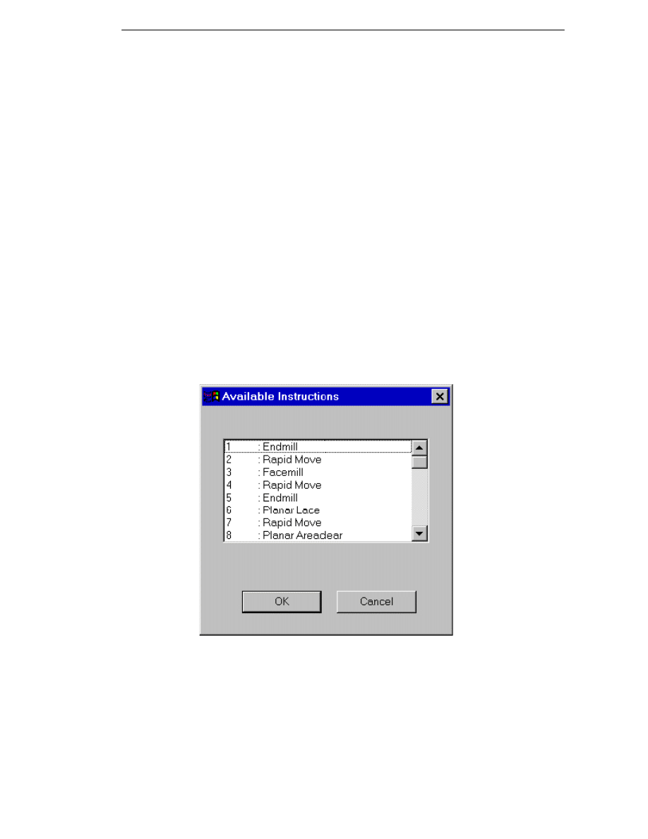
Building the Instruction List
The Instruction List is, simply, the list of all machining commands for the
current part. Each time a new machining command is used on the part, it is
added to the bottom of the list.
Commands that cannot be converted into CNC code (for example, viewing
and editing commands) do not appear on the list.
Example Instruction List:
You can also group instructions together as operations using Operation
(Instructions menu). This means that when editing the instruction list you
could edit individual commands or entire operations. Do not confuse these
with the integrated machining commands provided under the Operations
menu.
11

Manufacturing Basics
Changing the Machine Parameters
To check the values for the current machining sequence, use the Machine
Parameters (Verify menu) command. This displays a dialog box showing all
current machining parameters.
You can alter the conditions of the machining sequence at any time using the
Machine Parameters (M-Functions menu) command:
Depending on the manufacturing environment, some or all of the following
parameters can be altered:
Rapid 3D – Click in this box to allow the tool to rapid move in all three axes.
Each axis may accelerate to rapid at differing rates. There is therefore a
risk of collision as the resulting move is not easily predictable. Refer to your
machine tool documentation.
Sequence Name – Enter a new name for the current machining sequence.
Job Name – Select a job be entering the appropriate name or use the
Browse button to call up the Job Manager and select a job from the list.
Initial Plane* – Set the absolute height of the Initial Plane. Note that while
toolchange and home positions are defined in world co-ordinates the initial
plane is defined from the intial CPL of the sequence. These two datum points
may be different.
You must ensure that this height is clear of any obstruction including
holding devices and material.
Use this plane to move around the part at the rapid rate. See also Moving to
the Initial Plane.
Output Tolerance – Specifies the smallest distance that the Code Generator
can output in the final CNC file of the machining sequence. Also see
Conversion of Arcs to Lines.
Machine Tool – Select a Code Generator file for the machining sequence.
This file defines which machining commands are available and controls the
output of the CNC code.
To be able to successfully reselect a machine tool, the two machine tools
should have the same capability. For example, moving C axis operations to a
turning centre not equipped with a C axis control would result in an incomplete
machining instruction list.
Units* – Select the units that the final CNC code is to use. Any differing units
used in the model are automatically converted.
The default units are specified in the Code Generator file. You can select
between mm (millimetres) and inches.
Home* – Set the tool home position by entering the X, Y and Z world co-
ordinates.
Toolchange* – Set the toolchange position by entering the X, Y and Z world
co-ordinates.
*The marked parameters have default values that are set in the Code
Generator file.
For more information on the parameters on the Job Data tab, please refer to
Passing Job Data to the NC File.
12
EdgeCAM Manufacture - User Guide
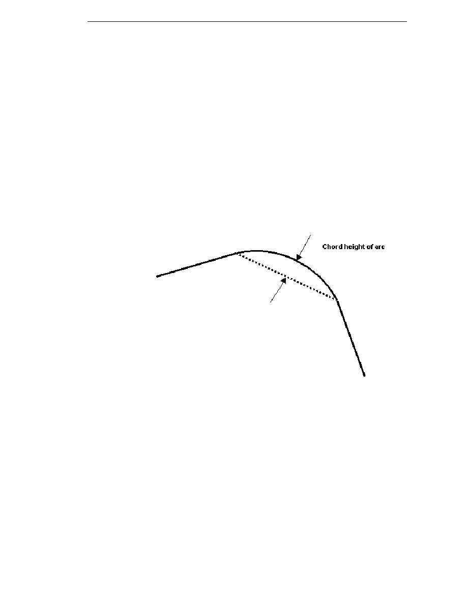
Conversion of Arcs to Lines
EdgeCAM converts an arc move to a linear move when the chord height of
the arc is less than the output tolerance of the machining sequence. The
output tolerance is normally set to the same precision as the controller's
decimal point format. For example 0.001mm or 0.0001 inch.
EdgeCAM performs this conversion to inhibit the output of potentially invalid
arc moves which could cause an error on the controller where
arcs have a radius greater than the control can interpret. This can be
encountered in smoothed surface toolpaths.
the arc start and end positions are so close that when formatted they are
the same position. This can result in the controller interpreting it as a
complete circle move.
the arc start or end positions in one axis are close enough to become the
same position when formatted. This can result in the controller reporting an
error that the point does not lie on the arc.
13

Manufacturing Basics
Selecting Tools
Before you can begin machining a part, EdgeCAM expects you to load a tool
of some description. This is so that the correct tool offsets and positioning from
the work can be calculated.
Until you load a tool in the turret, you are only allowed to position the turret
and select M-Functions commands. Once you have loaded a tool, all cycles
appropriate to that tool type can be used.
EdgeCAM provides these methods of loading tools:
Loading pre-defined tools from the ToolStore or Tool Library. Note that you
can set up where to find the ToolStore and the Tool Library using the Tool
Libraries tab of the Preferences (Options menu) command.
Entering the parameters defining a completely new tool.
Loading tools from an AutoTAS database.
Selecting from the ToolStore
To access the ToolStore:
Select ToolStore from the Tooling menu.
Click on the ToolStore
button.
Click Find on the General tab of the Milling Cutter dialog.
For further information on using the ToolStore, please refer to the context
sensitive help in the ToolStore application or the ToolStore chapter in this
manual.
14
EdgeCAM Manufacture - User Guide
Selecting from the Tool Library
Before proceeding, you should be familiar with the Tool Library. See Using
the Tool Library, and Searching for Records.
To load a tool from your default tool kit
See Defining a Machining Sequence for details on specifying the default
tool kit.
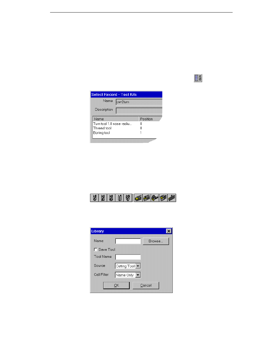
1. Select Load From Kit (Tooling menu) or click on the
button. This
dialog appears, listing the tools already saved to the default tool kit:
2. Select the appropriate tool.
3. Click on OK.
To load a tool from the Tool Library
1. Select from Turn, Thread, Bore, Groove, Parting Off or Milling Cutter
(Tooling menu) or click on a tool button:
EdgeCAM displays the parameter input window for that tool type.
2. Click on the Library button. The Library window appears:
3. Click on the OK button to search the source database.
4. Select an appropriate tool from the list.
15
Manufacturing Basics
To save a tool in the Tool Library
You must have selected a tool type from the Tooling menu or have clicked on a
tool button. This displays a parameter input window for that type of tool. Once
you have specified the parameters of a particular tool, you may want to save it
so that you can use the same tool later.
To save a tool
1. When you are satisfied with the values of each parameter, select the
Library... button.
The Library window is displayed.
2. Select the Tool Library database using the Source parameter. You can
only select Cutting Tools as you cannot save an Assembly or a Tool Kit
with this method.
3. Specify a reference Tool Name for the tool.
4. Click on the Save Tool box.
5. Click on OK.
Defining New Tools Interactively
Rather than load the tool information from a database, you can specify a
completely new tool, purely for use with the next cycles you select in the
current machining sequence.
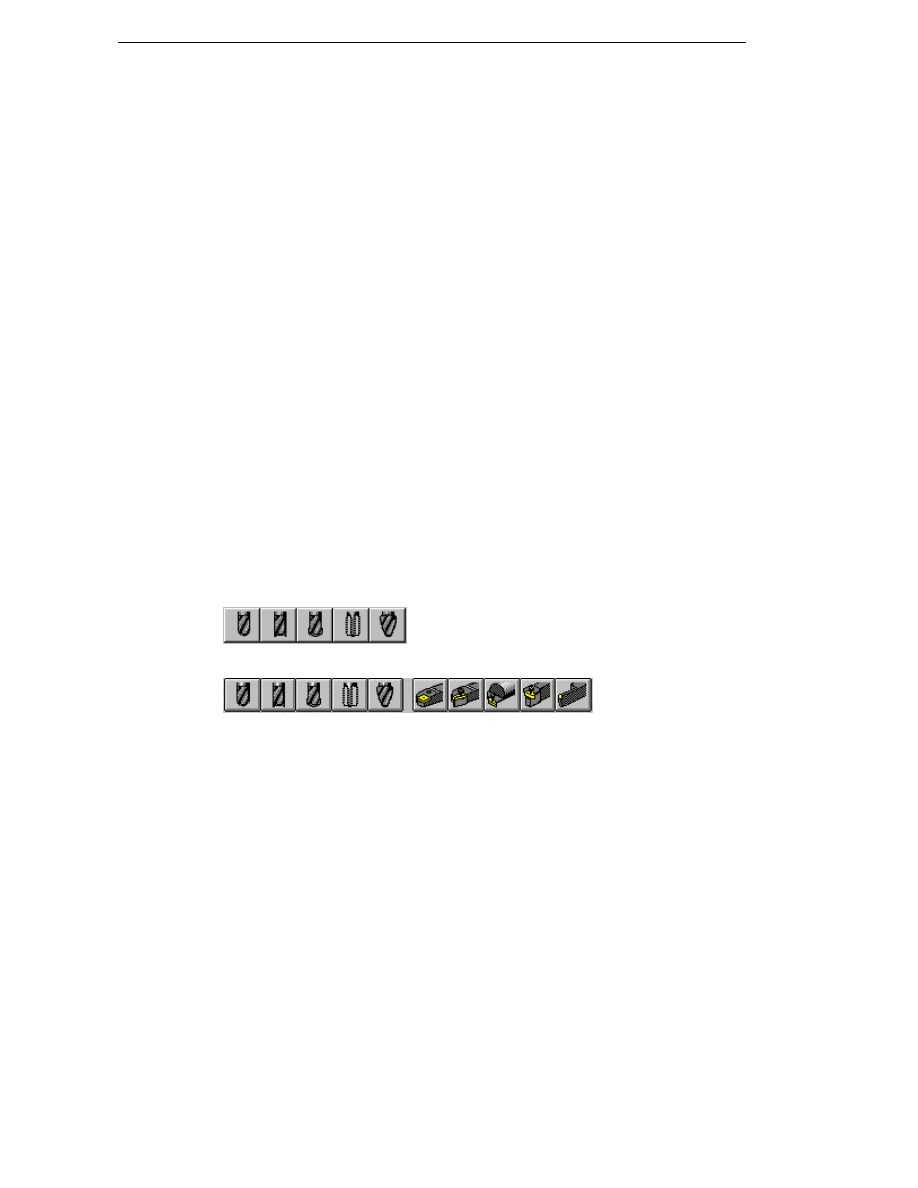
All tools can be selected from the Tooling menu or from the toolbar.
Milling Cutters
Turning Tools
Turn, Thread, Bore, Groove and Parting Off are considered to be fixed tooling,
while Milling Cutters can be either driven (powered tooling) or fixed. You
could also use a fixed drilling tool for making holes on the spindle centreline.
16

EdgeCAM Manufacture - User Guide
Selecting the Wire
Use the Select Wire (Cycles menu)
command to set the parameters
for the Wire Machine. This command lets you define the wire thickness and
height of the upper and lower guide to be used when you machine the part.
Diameter - Specifies the diameter of the wire.
Colour - Specifies the colour of the wire and any positional moves.
Upper Guide* - Specifies the height of the upper guide above the workplane.
Lower Guide* - Specifies the height of the lower guide above the workplane.
These guide height values will only be used if the Code Generator is set to
output at guide height.
* Guide height values are only applied to langhand output. Code Generators
working at guide heights should have taper mode disabled and 4-axis circular
moves should be converted to linear moves.
17
Manufacturing Basics
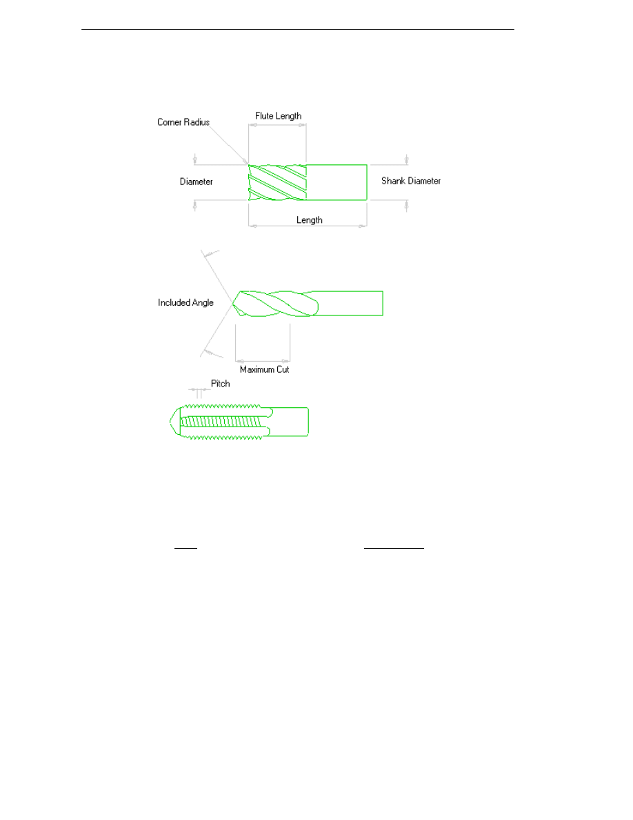
Milling Cutter Parameters
The parameters concerning the dimensions of the milling cutter can be seen
from these diagrams:
Number of Teeth – Specify the number of cutting teeth on the tool.
Comment – Enter any short notes here regarding the tool – these will appear
in the instruction list and in the NC output for the machining sequence.
Layer – Specify the layer on which the associated toolpath will be drawn.
Units – Specify the units in which the tool is defined.
Depth Type – Specify whether the setting point of the tool is taken to be at
the Point of the tool, or at the beginning of the Full Diameter of the tool.
Colour – Select the colour of the tool and the associated toolpath.
Turret Tab
Position – Specify the tool’s position number on the turret.
Zgauge – Specify the distance between the tool setting point and the tool
loading point.
Please note that the gauge length is specified in part units (not tool units).
18
EdgeCAM Manufacture - User Guide
Turning Tool Parameters
You may have more or fewer parameters than are given here. This is
because you are using a customised Code Generator file which alters those
commands and parameters that are displayed within EdgeCAM.
Comment - Enter a text string that is placed in the CNC file as a comment
when you generate code from the machining sequence.
Layer - Select the layer on which the tool is drawn.
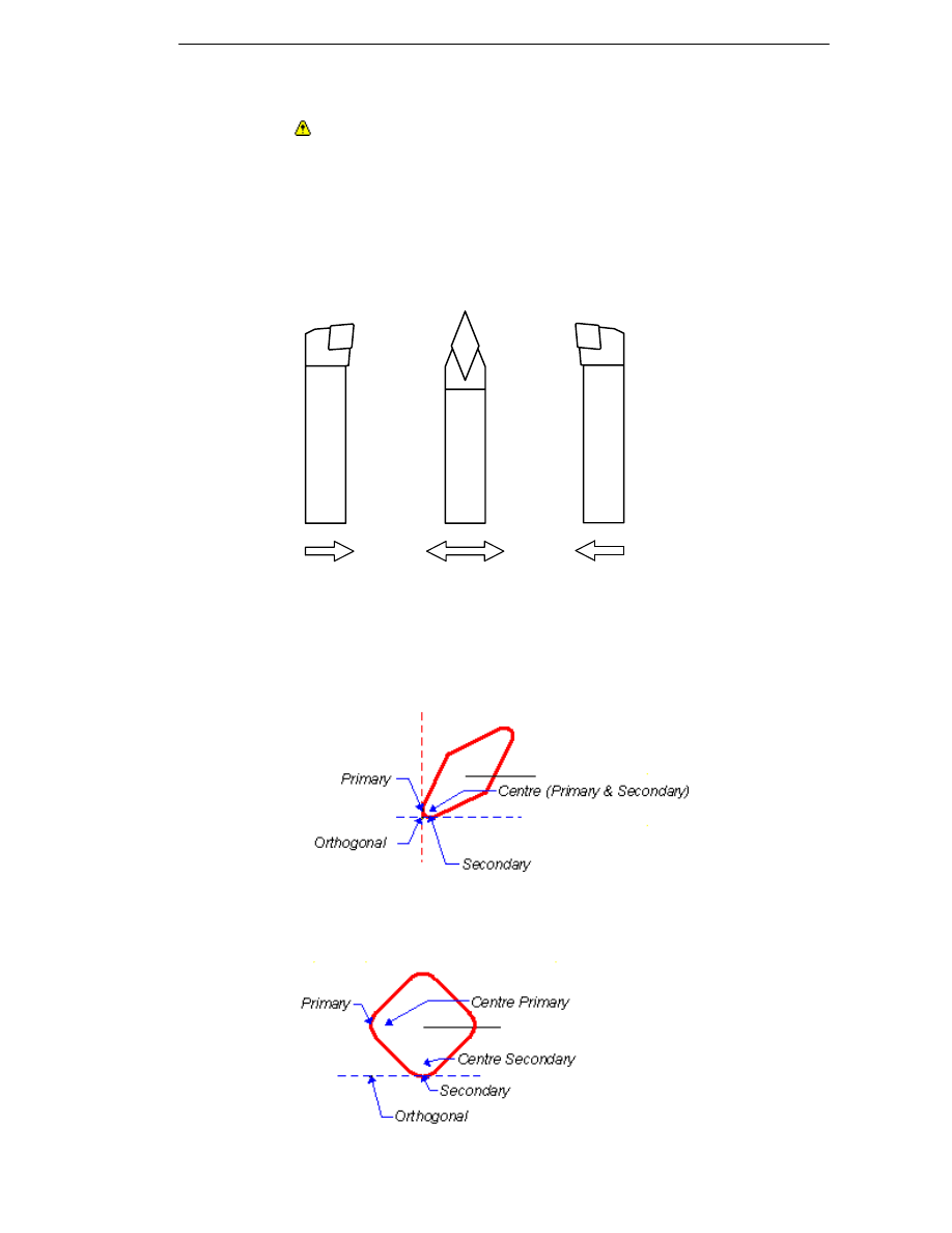
Hand of Tool - Select which side of the rotary spindle axis the tool cuts on:
Left Hand
Neutral
Right Hand
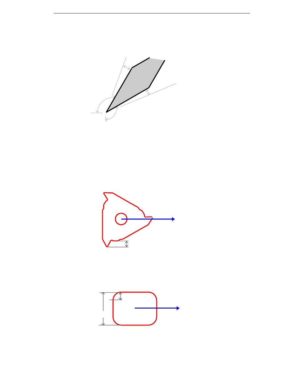
Gauge Point - Defines the Gauge Point of the insert, in relation to the long
(Z) axis of the tool. The Gauge Point can be set to the Primary, Secondary,
Centre (of the Primary or Secondary tip radius) and Orthogonal points of an
insert, and is usually positioned as follows:
19
Manufacturing Basics
These insert types use different Gauge Point locations:
Primary
Primary
Centre Primary
Centre
Secondary
Secondary
Orthogonal
Primary
Centre
Primary
Centre
Secondary
Orthogonal
Secondary
Centre
Primary
Centre
Secondary
Orthogonal
Secondary
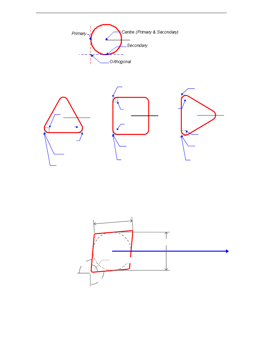
Specifying Insert Parameters
The insert's orientation is defined relative to the tool axis. This diagram is
based on a right handed turning tool:
Edge Length
Inscribed Circle
End
Angle
Included Angle
Tool Axis
Side Angle
End Angle - Define the angle between the tool axis and the end of the insert.
Side Angle - Define the angle between the tool axis normal and the side of the
insert.
20
EdgeCAM Manufacture - User Guide
End/Side Clearance Angle - Specify the clearance in degrees between the
End/Side Angle and the actual End/Side Angle to be used. These values are
measured relative to (and are deducted from) the End and Side Angles, and
should always be (small) positive values.
Here is an example insert and some example parameters:
End Clearance
Angle=3
End
Angle
=120
Side Clearance Angle=2
Side Angle=120
Included Angle - Define the angle between the end and side of the insert.
Edge Length - Define the length of the cutting edge of the insert.
Inscribed Circle - Define the diameter of an imaginary circle that could just
fit inside the outline of the insert.
Nose Radius - Define the radius of the corner at the cutting end of the insert.
Reach - Defines the depth that the insert can cut before the shank makes
contact with the material. This is only for Thread, Parting Off and Groove tools.
Reach
Style - Select the position of the insert to be at the End or Side of the tool.
This example shows a Grooving or Parting Off tool with Style = End.
Corner
Radius
Width
21
Manufacturing Basics
Corner Radius - Define the radius of the corner at the cutting end of the
insert.
Width - Define the width of the cutting edge of the insert, ignoring corner
radii.
Symbol - Select from a list of ISO insert symbol types.
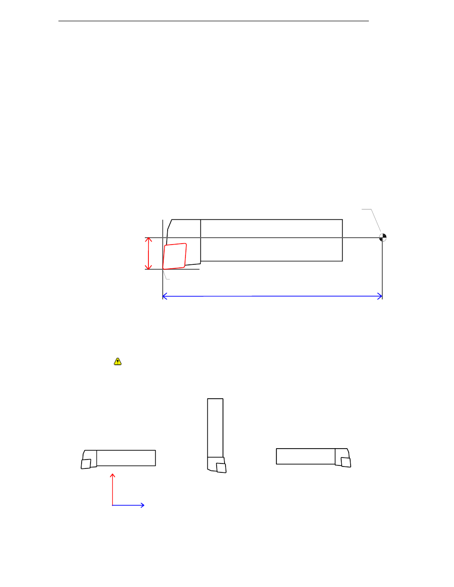
Specifying Turret Parameters
These parameters define the orientation of the tool to the Machine Tool Co-
ordinate System:
Position - Specify the position that the tool occupies on the turret (this
defaults to the last-used turret position).
Xgauge, Ygauge, Zgauge - Enter the distance of the Gauge Point from the
mounting point of the tool in the X, Y and Z axes.
Tool Mounting Point
Xgauge
Gauge Point
Zgauge
Ygauge is only used on Driven tooling and when Y axis mode is enabled to
allow for the tool to have a distance defined off the centreline of the spindle.
Please note that the gauge length is specified in part units (not tool units).
Orientation – Select from Axial, Radial and Reverse Axial to define the
position of the tool axis relative to the Machine Tool Co-ordinate System:
Axial
Reverse Axial
X axis
Z axis
Radial
22
EdgeCAM Manufacture - User Guide
Angle - Specifies the angle the tool makes with the Machine Tool Co-
ordinate System's Z axis. This is used for finer control over the tool than by
using the orientation. To activate the field, set the Orientation parameter
(General tab) to <NONE>.
Reverse – Mark this box to use the tool rotated 180
° about its own axis:
Right Hand tool,
Radial orientation
with Reverse off
X axis
Z axis
Radial orientation
with Reverse
selected
Whether you reverse the tool or not depends on the direction of the machine
spindle's rotation.
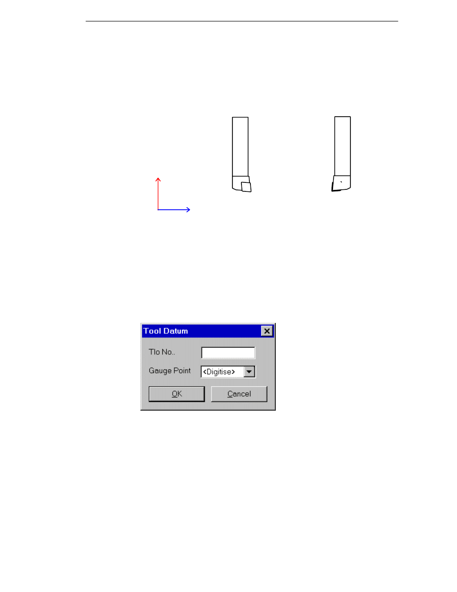
Selecting a New Tool Datum
Use the Tool Datum (Tooling menu) command to select a gauge point and
offset for the insert of a fixed tool.
Offset - Select the offset register for the tool, as specified by the machine tool
controller. This is only valid if you are using controller compensation. Usually,
the turret number is used to determine the offset register. However, you may
want to use multiple registers, for example when turning a part with different
diameters, using different offsets to compensate for tool deflection. For more
details on the gauge point of a tool, see Specifying Turning Tool Parameters.
23
Manufacturing Basics
Saving Tool Graphics
Saving tool graphics in the ToolStore
The Save Tooling Graphics
command on the Tool Graphics toolbar
allows you to save a tool/holder graphic as a .csv file.
The parameters for the command are:
Tool Graphics – Saves current tool graphics data to a .csv file. Click Browse
to look for an existing file.
Holder Graphics – Saves current holder graphics data to a .csv file. Click
Browse to look for an existing file.
Saving tool graphics in the Tool Library
The Save Tooling Graphics (File menu) command allows you to save a
drawing of a tool as a .gra Tooling Database graphics file.
Once you have set the parameters, click on OK. For further information on
individual parameters, please refer to the context sensitive help.
You must then digitise the required datum point for the tool, the first and
second points on the z axis of the tool, entities to define the tool graphics
image, and any entities to de-select.
Note that you can use the Run Executable (Custom menu) command to run
the toolgra.exe PDI program, which generates entities from any on-screen tool
simulation graphics. You can then select these entities with the Save Tooling
Graphics command, and store them in the Tool Library.
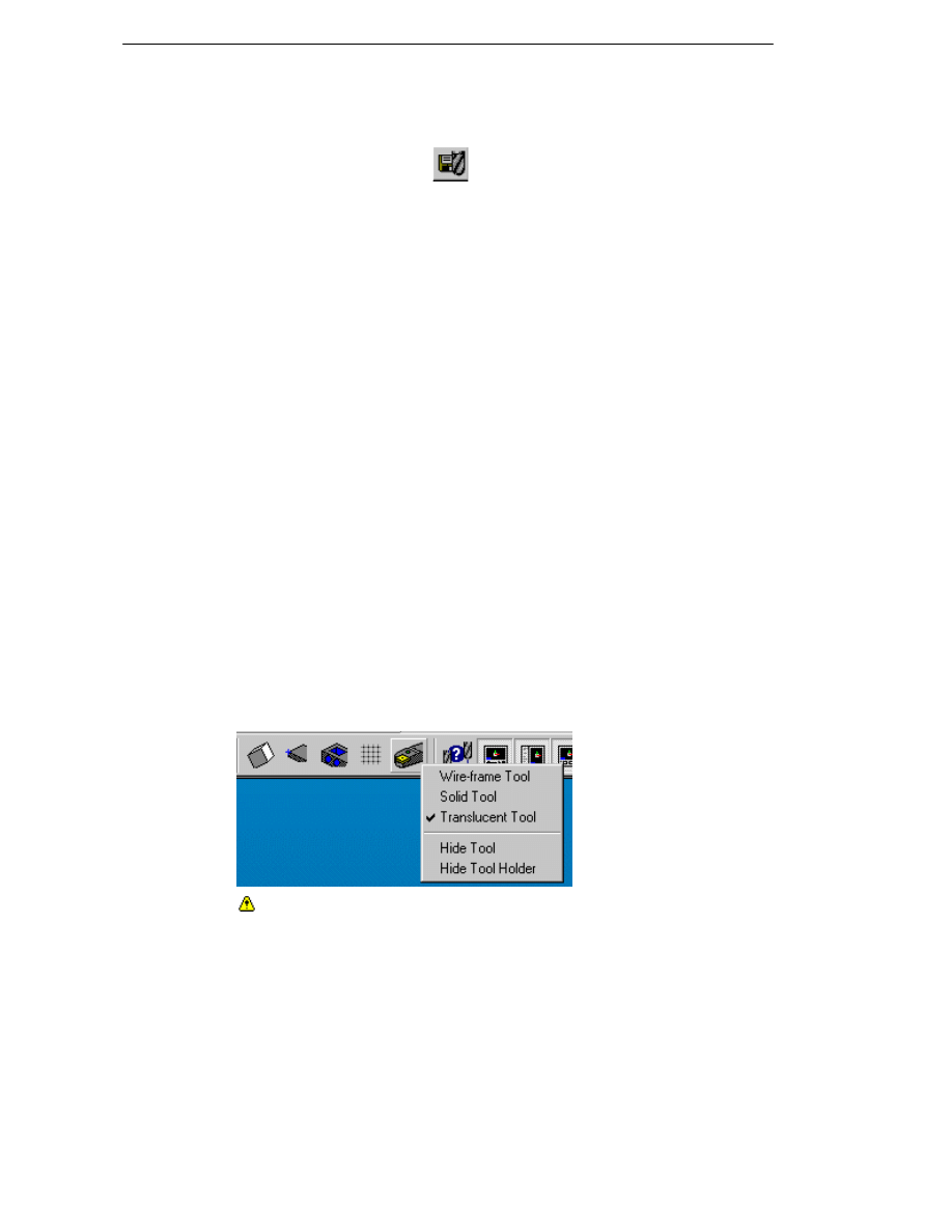
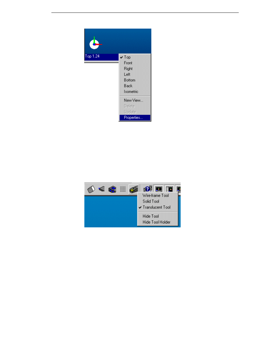
Displaying the Tool
By default, EdgeCAM displays the tool at its last position. The Toggle Tool
icon on the Display toolbar allows you to specify how tools are displayed on
the graphics screen:
Check the Hide Tool option if you do not want to display the tool. Please
note that this option is unchecked by default.
24
EdgeCAM Manufacture - User Guide
Alternatively, right click on the view status bar and select Properties.
On the Properties dialog, choose between the Wireframe, Solid or
Translucent options from the Display parameter on the Tool tab.
Check the Hide option if you do not wish to display the tool.
Displaying the Tool Holder
By default, EdgeCAM displays the tool and the tool holder at its last position.
The Toggle Tool icon on the Display toolbar allows you to specify how tools
are displayed on the graphics screen:
Check the Hide Tool Holder option if you do not want to display the tool.
Please note that this option is unchecked by default.
25

Manufacturing Basics
Setting Feeds and Speeds for Milling and
Turning Tools
Setting Speeds and Feeds Manually
You can specify the tool spindle speed and movement rates in the parameter
input dialog box for any machining cycle. These speeds and feeds can be input
manually for each cycle or you can use automatic defaults derived from
material and tool technology tables.
The common parameters are:
Feedrate – Specifies the feed rate in the workplane in units per revolution
(for a Boring tool, for example) or in units per minute. You can select the type
of feed using the Feed Type (M-Functions menu) command.
Plunge Feed – Specifies the vertical feed rate.
Speed – Specifies the rotational speed of the tool on a milling centre in
revolutions per minute.
On a turning centre, this refers to the spindle speed, measured in units per
revolution. This is overridden if you have selected constant surface speed
using the CSS (M-Functions menu) command. CSS is normally only used
with turning centres with fixed tooling (but not drills and taps).
If you select another cycle, these speeds and feeds are carried over and
used again as the default values. These can be overridden or accepted.
Setting Speeds and Feeds Automatically
You can specify the tool spindle speed and movement rates for any
machining cycle. However, EdgeCAM automatically calculates “speeds and
feeds” for the tool based upon data previously specified.
Using the technology database in the ToolStore
Material and Insert records are held in the Technology database and can be
accessed through the Technology tab of all tools in the ToolStore. Values
loaded from the Technology database are shown "greyed out" as they cannot
be directly edited. These values are used by the system and are passed to
EdgeCAM operations and cycles.
For further information on using material and insert data, please refer to the
help in the ToolStore application.
26

EdgeCAM Manufacture - User Guide
To select material technology values in the Tool Library
Material technology tables are held in the Material Technology database in
the Tool Library, but you can access them through the Model (Options
menu) command in Design mode.
For more information on using the Tool Library databases, see Searching for
Records.
1. Select the Model (Options menu) command in Design mode.
Specify a Rigidity factor. If the material is weak or the clamping system
exerts low holding forces, then you need to adjust this downwards. For
example, a factor of 50% halves the theoretical speeds and feeds. This
applies to all tools used for the part.
2. Search the database.
All records matching your search are displayed.
3. Select the material data table you want to use.
To select tool technology values
1. Use the Technology (Tooling menu) command in Manufacture mode if
you want to select any tool or material technology data for the current tool.
2. Use the Cut Type parameter to determine which set of material technology
values you want to use from the current Material Technology table. Select
from None, Rough, Medium or Fine. The default Cut Type is Medium.
Select None to manually specify feed and speed parameters when the
parameter input box for each cycle that you select for the current tool.
3. You can also specify a percentage Factor by which to multiply the values
in the material technology tables. This is used to adjust the theoretical
speeds and feeds for this tool only. For example, a long series endmill
needs to be driven slower than a short series endmill.
4. Click on OK.
27
Manufacturing Basics
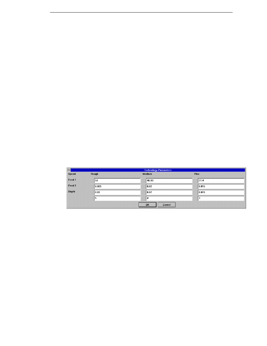
Viewing the Current Technology Values
Select the Technology (Verify menu) command.
A window displays the current technology values, as in this example:
Technology
(Mild
Steel)
Rigidity
100%
Technology Factor
100%
DEPTH
SPEED
FEEDRATE
PLUNGE
FEED
(mm)
(rev/min)
(mm/rev/tooth)
MEDIUM
4.00
250.00
0.25
0.25
(Cut Type)
tooling
100%
50%
100%
100%
(Final values)
4.00
125.00
0.25
0.25
The Rigidity and Technology Factor are multiplied with the values from the
Material Technology table to produce the corrected values. The tool’s
Technology values (measured in percentages) are now multiplied with the
Material Technology values. This increases or decreases the feeds and speeds,
depending on the grade of insert and the toughness of the material. The
material speed and feed values are based upon the material being cut with a
certain tool grade. If a tool has been selected where the grade of insert is
inferior, the tooling percentages would therefore be lower to reflect the lower
cutting performance of the tool.
The final values are what EdgeCAM uses as the default feeds and speeds for
all cycles.
Material
Technology
X
table
Rigidity
factor
Technology
X
factor
Tool
X
Technology
table
=
Calculated
Speeds and
Feeds
28
EdgeCAM Manufacture - User Guide
Material Technology Table
This defines the speeds and feeds to be used for different materials. Material
speeds and feeds are based on machining data using a standard tool grade.
Tool Technology Table
This defines the modification to the Material Technology Table in percentage
terms. For example, the tool used for the standard grade would use a factor of
100%, but a tool of a higher standard may use 130%, thus increasing the
Material Technology Table values by 30%.
You can select the:
Rigidity – Specified using the Rigidity parameter (a percentage) in the
Model (Options menu) command.
Technology Factor – Specified using the Factor parameter (a
percentage) in the Technology (Tooling menu) command.
Cut Type – Sets the column of the Material Technology table to be used.
Specified using the Cut Type parameter in the Technology (Tooling
menu) command.
Defining New Material Technology Tables
You may find that you need to create a completely new material technology
table for your typical machining tasks. In this case you must define a new
table record in the Material Technology database in the Tool Library.
You can enter data into these tables based either on data from tool
manufacturers’ handbooks or from your own experience.
Remember which units you are working in – millimetres or inches. You cannot
mix values within a single record, but you can have two records however, one
for inches and one for millimetres. These records can have the same name (as
long as they are using different units).
Rough, Medium or Fine values can be selected for a cycle.
The values for Surface Speed are in either metres per minute or feet per
minute.
The values for Feed 1 and Feed 2 are in “chip per tooth” (millimetres or
inches per tooth).
The values for Depth are in millimetres or inches.
29
Manufacturing Basics
To create a new record in the Material Technology database
Before proceeding, you should be familiar with the Tool Library. See Using
the Tool Library, and Searching for Records.
1. Switch to the Program Manager by holding down the Alt key and
repeatedly pressing the Tab key, releasing the Alt key when the box
labelled Program Manager is displayed.
2. Select the Tool Library icon
in the EdgeCAM program group.
The Tool Library window appears.
3. Select Material from the Technology menu.
The Material search window appears.
4. Enter search parameters for the new table.
5. Click on OK. The Tool Library searches for and displays a list of any
matching records.
6. Select the Insert operation control. The Insert Record window appears.
7. Enter the parameters of the new record.
8. Click on OK to save the record.
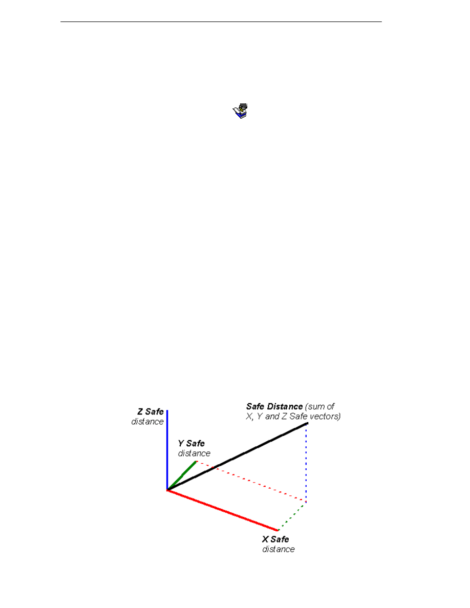
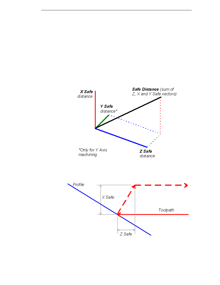
Selecting a Safe Distance for the Tool
Use the Safe Distance (M-Functions menu) command to specify a safe
distance for the tool in each of three dimensions. EdgeCAM ensures that the
tool maintains these distances from the component between machining
passes.
The default values are:
1mm (if you are using metric part units)
.05” (if you are using imperial part units)
In some circumstances, the safe distance must be a vector instead of X, Y
and Z distances. In these cases, the vector sum of the safe distances is
used:
30
EdgeCAM Manufacture - User Guide
Selecting a Safe Distance for the Turning
Tool
Use the Safe Distance (M-Functions menu) command to specify a safe
distance for the tool in each of two dimensions (or three dimensions if using Y
Axis machining). EdgeCAM ensures that the tool maintains these distances
from the component between machining passes.
The default values are:
1mm - (if you are using metric part units)
.05" - (if you are using imperial part units)
In some circumstances, the safe distance must be a vector instead of Z, X
and Y distances. In these cases, the vector sum of the safe distances is
used:
For Rough Turning cycles, a Safe Distance move is added to the end of a
pass:
31

Manufacturing Basics
Using Miscellaneous (M-) Functions
The M-Functions menu contains several standard commands, but it also
contains commands which EdgeCAM takes from the Code Generator file.
These commands are specific to the machine tool corresponding to the Code
Generator.
You can find out which miscellaneous functions are available by using the M-
Functions (Verify menu) command.
Which parameters appear in the dialog depend on the machining discipline
and the Code Generator you are currently using. The list of available M-
Functions includes:
Program Stop/Optional Stop
This command from the M-Functions menu is used to insert a program stop
(for example, M0) or optional stop (for example, M01) into the instruction list. It
is usually used where the machine tool cannot automatically change tools, and
the machine tool must be stopped so that the operator can manually change
the tool.
It can also be used in process inspection, when clearing swarf, moving
clamps and so on.
Coolant Mist/Flood/Off
These M-Functions menu commands control the state of the machine tool’s
coolant system.
The Code Generator file controls the machine tool’s default coolant state.
Inserting a Dwell
Use the Dwell (M-Functions menu) command to dwell or pause the currently
selected turret.
Changing the Feed Type
You can change the feedrate type of the tool from feed per minute to feed per
revolution using the Feed Type (M-Functions menu) command.
Selecting the Input Mode
You may want to switch between co-ordinate systems before entering
positional data for creating geometry or specifying machining cycles.
Using the Input Mode (M-Functions menu) command, you can choose
between:
Tool Local - Specifies the Z axis as equivalent at all times to the tool axis.
This allows you to easily specify distances relative to the tool's current
position.
Machine Tool - (Default) Any co-ordinate data input is in terms of the
Machine Tool Co-ordinate System.
32
EdgeCAM Manufacture - User Guide
Selecting Constant Surface Speed
As a fixed tool cuts down towards the spindle of a turning centre, the cutting
speed decreases as the circumference of the turned part decreases.
To ensure that the speed of the tool over the surface of the material stays
constant (a condition known as Constant Surface Speed, or CSS), use the
CSS (M-Functions menu) command.
If you mark the CSS box, EdgeCAM uses constant surface speed (as the tool
approaches the centreline, the spindle speed increases).
If you want to return to using the default condition of fixed spindle speed, use
this command again but make sure that the CSS box is blank.
Update Fixtures
This command allows you to select and update fixtures for a machining
sequence at anytime during the sequence.
At the start of the machining sequence it is possible to nominate the initial
fixture setup. Machining will then be carried out as usual. If the fixture setup
then changes midway through a machining sequence (for instance when
clamps are moved) you can use the command to update the fixture setup.
Fixture entities must be predefined using the Stock/Fixture (Geometry menu)
command prior to using this function.
The initially nominated fixtures will be taken through into the Simulator. The
Simulator will subsequently update the fixture display during its runtime when
an Update Fixtures command is encountered.
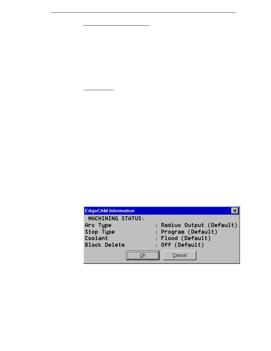
Checking the Miscellaneous Functions
You can check the selections that have been made using M-Functions menu
commands using the M-Functions (Verify menu) command.
A window should appear similar to this:
The actual items that appear depend upon your current Code Generator file.
Each Code Generator can add extra functions to the M-Functions menu.
These functions can be switches (for example, Coolant On/Off) or values (for
example, New Offset). The Code Generator assumes one of the options as a
default (Coolant is assumed to be on unless otherwise specified). Therefore, if
the function has not been used, the machine status reports -DEFAULT as
shown above.
33
Manufacturing Basics
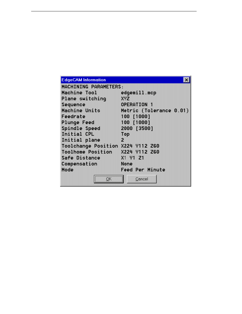
Checking the Part
Verifying the Machining Parameters
Use the Machine Parameters (Verify menu) command to see the current
selections for the current machining sequence.
A window appears similar to this:
The actual items that appear depends upon your current Code Generator file.
This is listed here as the Machine Tool.
34
EdgeCAM Manufacture - User Guide
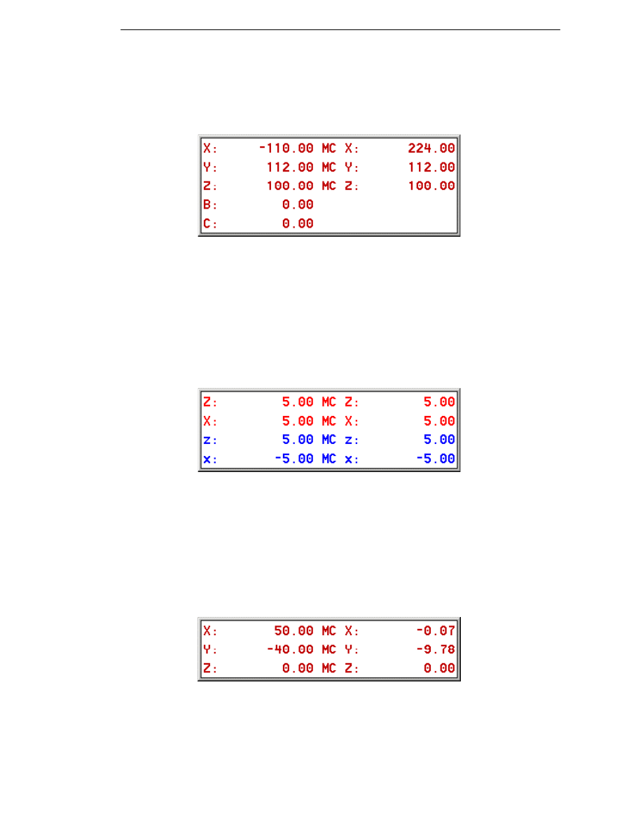
Viewing the Machine Datum Co-ordinates
You can view the Machine Co-ordinates by switching on the Status Bars,
Machine Datum Co-ordinates option from the View menu. While you are in
Manufacture mode, a window shows the current co-ordinates of your tool:
The column on the left shows the co-ordinates of the tool with respect to the
active CPL (and can be displayed on its own by using the Status Bars, CPL
Co-ordinates option).
The column on the right shows the co-ordinates of the tool with respect to the
Machine Datum (which you set by checking the Machine Datum box when
defining a new Machining Sequence). The machine (MC) co-ordinates
update at the end of each cycle.
Turning Example
The top two sets of co-ordinates are for the Upper Turret, while the bottom
two are for the Lower Turret.
The column on the left shows the co-ordinates of the tool(s) with respect to the
active CPL (and can be displayed on its own by using the Status Bars, CPL
Co-ordinates option). The column on the right shows the co-ordinates of the
tool(s) with respect to the Machine Datum (which you set by checking the
Machine Datum box when defining a new Machining Sequence). The machine
(MC) co-ordinates update at the end of each cycle.
Wire Erosion Example
The column on the left shows the co-ordinates of the wire as it passes
through the XY plane, with respect to the active CPL (and can be displayed
on its own by using the Status Bars, CPL Co-ordinates option). The column
on the right shows the co-ordinates of the wire with respect to the Machine
Datum (which you set by checking the Machine Datum box when defining a
new Machining Sequence). The machine (MC) co-ordinates update at the
end of each cycle.
35
Manufacturing Basics
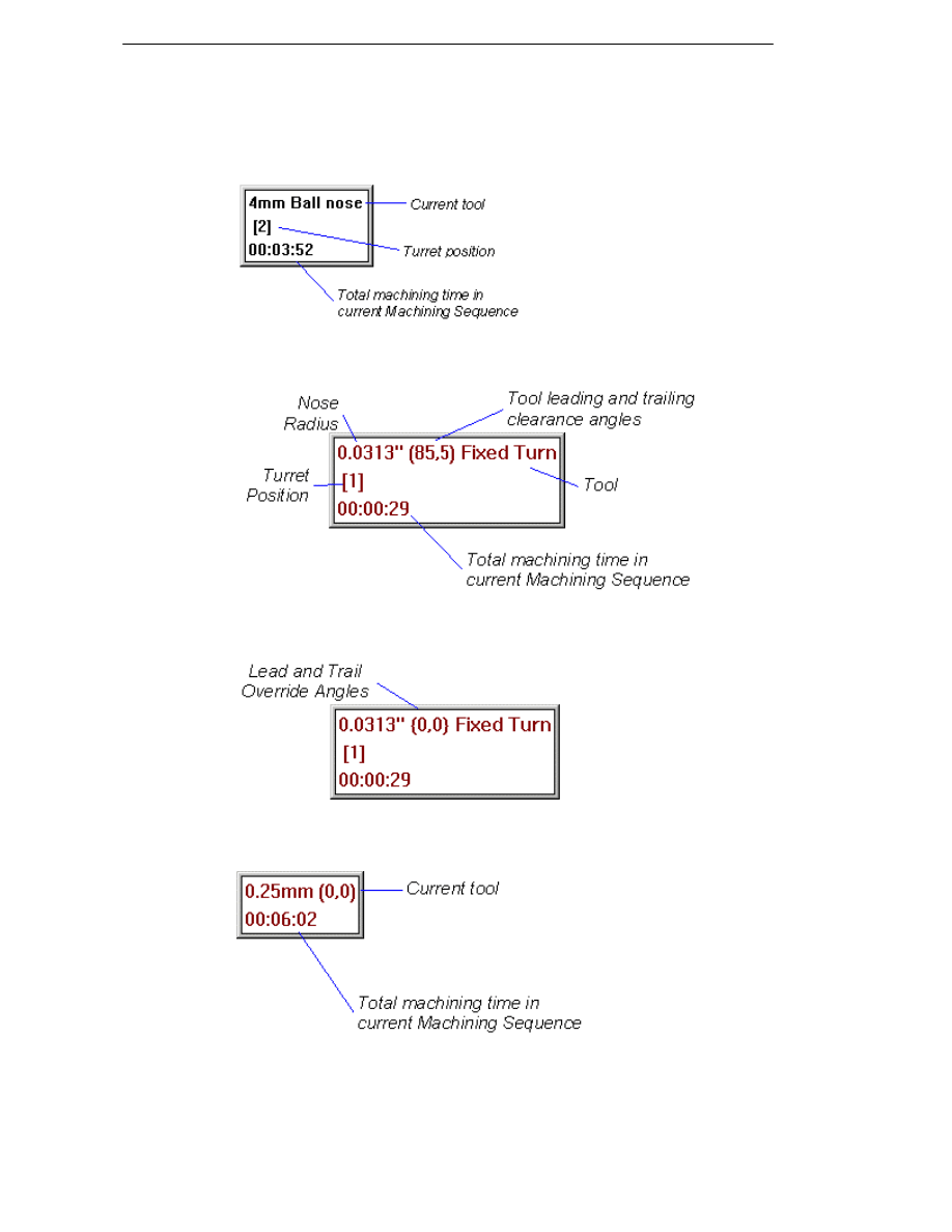
Viewing Information on the Part
You can view information on the current part by switching on the Status Bars,
Part Information option from the View menu.
Milling Example
Turning Example
If Override Angles have been specified for the tool, these are shown in place
of the clearance angles, in { } brackets:
Wire Example
The numbers in brackets are the Upper and Lower Guide heights (see
Selecting the Wire for details).
36
EdgeCAM Manufacture - User Guide
Moving the Tool
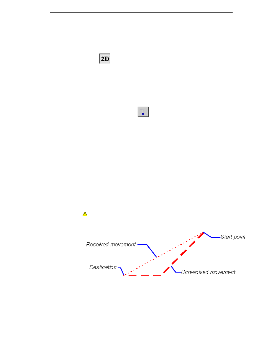
The type of tool movement available depends the machining discipline used.
In the Milling environment, the type of movement also depends on whether the
2D Snap
button is selected. The default is for this button to be selected.
If the 2D Snap button is selected, the tool can only move in the workplane at
the current height.
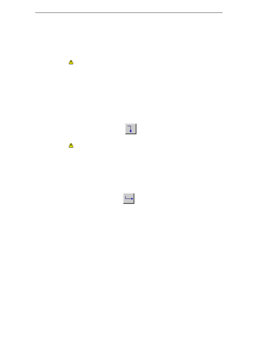
Moving at the Rapid Rate (Milling and
Turning environment)
Use the Rapid (Move menu)
command to move the tool in a straight
line at the rapid rate. The command is usually used to place the tool in a
position to begin a new machining operation or toolchange.
You can change the tool movement at the rapid rate to be in all three axes.
To do this, select the Machine Parameters (M-Functions menu) and click
on the Rapid 3D parameter to put a cross in its box.
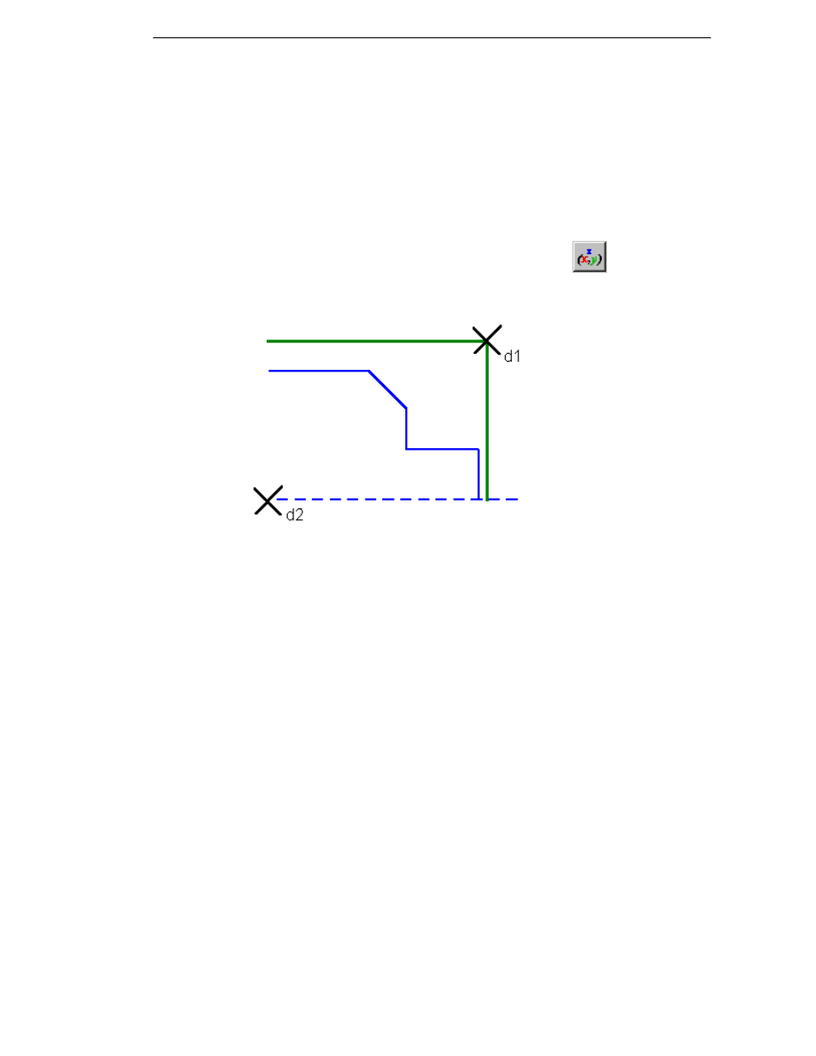
Important Note
Machine tools can move from point to point in two ways (see example):
Resolved – When moving from point to point the toolpath is linear. This
means that one axis may move slower than the other, so that a straight
line is achieved between points.
Unresolved – When moving from point to point both axes accelerate at the
same rate until one axis has reached its position. The other axis then
completes its move, thereby producing a ‘dog-leg’ move.
The Code Generator has a parameter that sets the rapid type for your
machine.
It is important that the correct display is shown so that you can see if the
toolpath has inadvertently collided with the part. Please refer to your machine
tool manual for details.
37
Manufacturing Basics
In the Milling environment, if Rapid 3D is not selected, the default method
depends on whether the tool is moving:
a. Out of the work- the tool moves in the Z+ direction first, then in the
workplane.
b. Into the work – the tool moves in the workplane first, then in the Z-
direction.
Note that some machine tool controllers can override the programmed
rapid in three dimensions, in a similar manner to cases a and b described
above. Please consult your machine tool manual for details.
You can also specify a different colour for your rapid moves. Select the
Colours (Options menu) command and set the Rapids & Normals
parameter.
Also see Editing Co-ordinates of Rapid and Feed Moves
Moving the Wire at the Rapid Rate
Use the Rapid (Move menu)
command to generate a toolpath for a
move in a straight line at the rapid rate.
Warning: Do not use this command while a wire is threaded.
Note that the Code Generator may already be configured to cut the wire and
re-thread at the new location.
Also see Editing Co-ordinates of Rapid and Feed Moves
Moving at the Feed Rate
Use the Feed (Move menu)
command to move the tool or wire to a
position at the feedrate. It should be used when the tool may come into
contact with the material.
Feed moves can also be used as “freehand” machining commands where
more complex machining cycles are unnecessary.
In the milling environment, if 2D Snap is off, the feed move ignores all Z
information (for example, from an entity digitise).
Also see Editing Co-ordinates of Rapid and Feed Moves
38
EdgeCAM Manufacture - User Guide
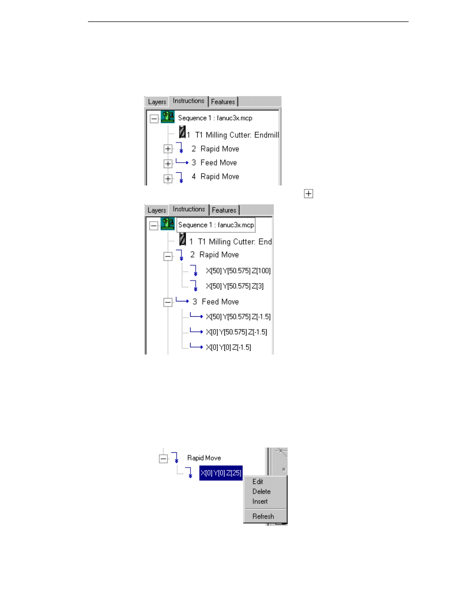
Editing Co-ordinates of Rapid and Feed
Moves
All rapid and feed moves are listed on the Instructions tab in the EdgeCAM
browser window on the left-hand side of the screen.
The entries can be expanded by clicking on the
sign.
Note that displaying the individual co-ordinates in feed and rapid moves can
slow down EdgeCAM when working with a part containing a large number of
instructions. Uncheck the Display Co-ordinates option on the Toolpaths tab
of the Preferences (Options menu) dialog if you do not wish to display the co-
ordinates.
As you select co-ordinates in the browser, the node (a single position) in the
toolpath is highlighted in the graphics area. A right click on a co-ordinate in
the browser calls up the context menu which allows you to edit or delete
individual existing co-ordinates or to insert new co-ordinates:
39

Manufacturing Basics
Editing co-ordinates
Right click on an existing co-ordinate in the browser and select Edit from the
context menu. You can now specify new co-ordinates for this position by a
using a free digitise, snapping to an entity or using co-ordinate input and/or
construction tools.
Note that ‘modal’ values inherited from the previous line are shown as blank.
Inserting new co-ordinates
Right click on an existing co-ordinate in the browser and select Insert from
the context menu. You can now specify a new co-ordinate position by a using a
free digitise, snapping to an entity or using co-ordinate input and/or
construction tools. The new position is inserted before the selected node.
If incremental values are input or if only some of the required co-ordinates
are given, the inserted node will be based on the position given in the
previous node.
If a co-ordinate value which has dependants in subsequent co-ordinate
nodes or move instructions is changed then those dependent values
(incremental or blank) will also update automatically.
(Milling only) Use of the 2D Snap option when creating co-ordinates will result
in Z values being modal, based on the last specified Z height.
Deleting co-ordinates
Right click on an existing co-ordinate in the browser and select Delete from
the context menu. Multiple nodes can be deleted by holding down the “shift”
or “control” key when selecting a range or multiple individual co-ordinates. If
you select all of the co-ordinates of a rapid or feed move for deletion, the
whole instruction will be removed.
If you make changes to the instruction list, the display is not updated
automatically. Use the Refresh option to ensure that the instruction list is
displayed correctly in the browser window.
Note:
Double clicking on an a move or individual co-ordinate calls up the
rapid/feed move dialog. Checking the Coord Input box allows you to
change the position of the toolpath(s) by using free digitises, entity
digitises and/or explicit co-ordinates. However, when this option is
selected the original toolpath is deleted and you need to re-specify all
positions for the toolpath without reference to the originals.
If reference co-ordinates are used, the browser shows both the reference
point and the required offset from it, e.g. (X 0.000 Y 50.000 Z 0.000) + X10.
40
EdgeCAM Manufacture - User Guide
Moving the Tool in an Arc at the Feedrate
Milling and Turning environment only
Use the Arc (Move menu) command to move the tool in a circular motion in
the workplane at the specified feedrate.
Arc moves can also be used as “freehand” machining commands where
more complex machining cycles are unnecessary.
2 Point – This parameter controls how the arc move is defined.
If you check the box, you are prompted to digitise a midpoint and an
endpoint for the arc move.
If you leave the box unchecked, you are prompted to digitise the endpoint
of the arc. The arc leaves the last move at a tangent and finishes at the
endpoint.
Moving the Tool around a Co-ordinate Axis
Milling environment only
Use the Angular (Move menu) command to move the tool with reference to
one or more co-ordinate axes.
These parameters specify the direction of motion:
X, Y, Z Co-ordinate – Specifies the movement along the X, Y or Z axis in
part units.
A, B, C Co-ordinate – Specifies the movement around the X, Y or Z axis in
degrees. Your Code Generator must be capable of supporting these
movements for these to be displayed.
You may also specify the feeds, speeds and whether the move is to be at the
Rapid or Feed rate.
Moving the Tool to the Toolchange Position
Milling and Turning environment only
The default toolchange position is defined in the Code Generator file, and is
specified relative to the Machine Datum and in the orientation of the Initial
CPL.
To move the tool to the toolchange position
Use the Toolchange (Move menu)
command to return the tool to its
toolchange position.
If you use the button, the tool moves to the three dimensional location
specified in the Code Generator and machine parameters.
41
Manufacturing Basics
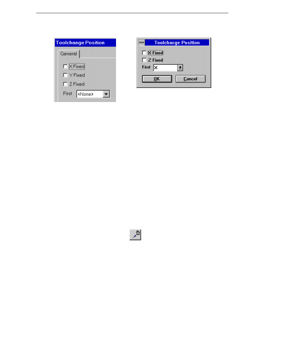
If you select the command, you can specify these parameters:
Milling
Turning
You might want to simply move the tool
You might want to simply move the tool up in
up in Z to the toolchange position rather X to the toolchange position rather than
than moving the tool to its default XYZ
position. To do this, lock the X and Y
moving the tool to its default ZX position. To
do this, lock the Z position by checking the Z
positions by marking the X Fixed and Y Fixed box.
Fixed boxes.
You can also specify the First axis to
move the tool in.
You can also specify the First axis to move
the tool in. This is useful when retracting
tools from features such as bores and
grooves, where the tool can collide with the
component.
The default toolchange position may be changed using the Toolchange
button in the Machine Parameters (M-Functions menu) command.
Moving the Tool to the Home Position
The default home position is defined in the Code Generator file, and is
specified relative to the Machine Datum and in the orientation of the Initial
CPL.
Use the Home (Move menu)
command to move the tool to its home
position. In Milling and Turning, the parameters are similar to those of the
Toolchange move.
The home position may be changed using the Tool Home button in the
Machine Parameters (M-Functions menu) command.
42
EdgeCAM Manufacture - User Guide
Moving to the Initial Plane
Milling environment only
Use the Initial Plane (Move menu)
command to move the tool to the
Initial Plane.
The Initial Plane is a height at which the tool is safe to move without any risk
of colliding with any part of the workpiece, clamps or fixtures. The default
value is taken from the Code Generator file.
You can set the height of the Initial Plane by specifying a value for the Initial
Plane parameter in the Machine Parameters (M-Functions menu)
command.
Note that while toolchange and home positions are defined in world co-
ordinates the initial plane is defined from the intial CPL of the sequence.
These two datum points may be different.
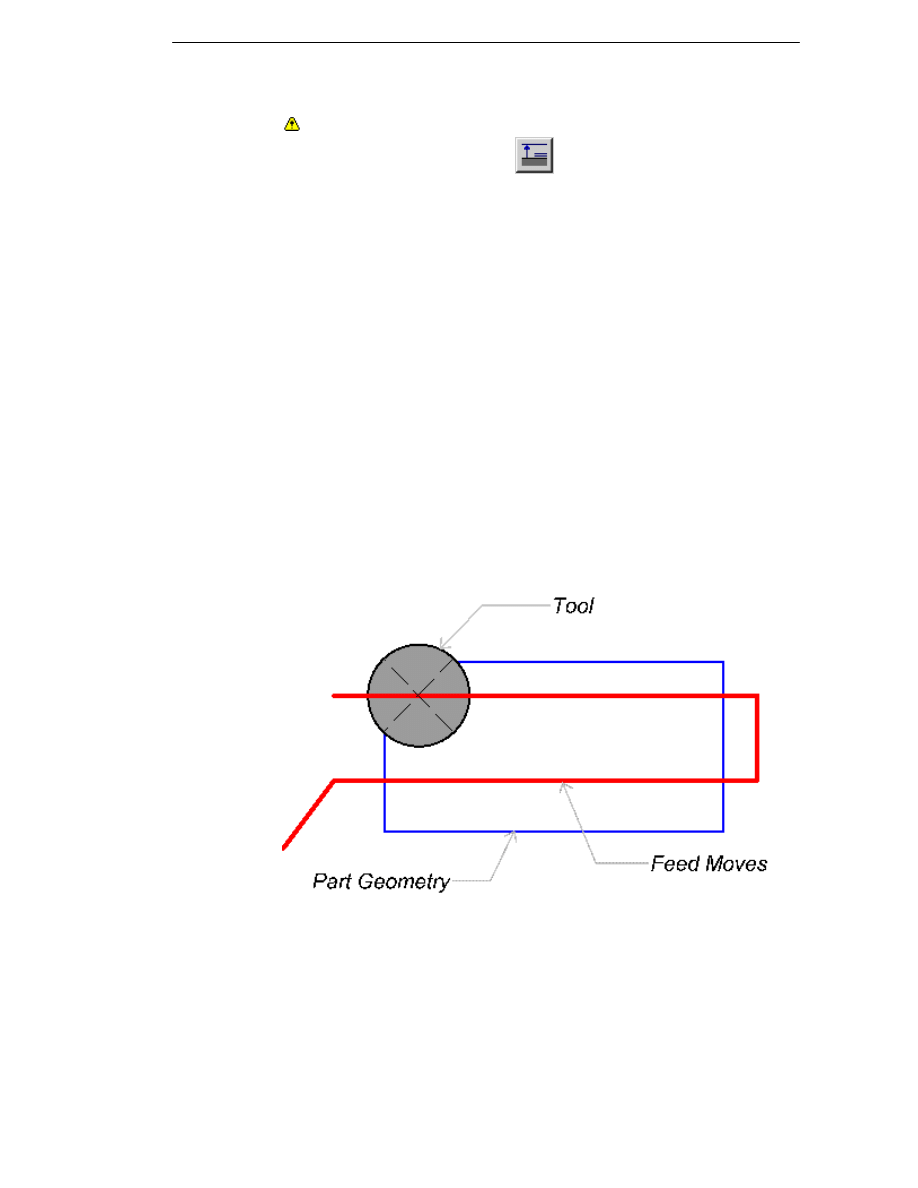
Freehand Milling
Rather than use specific commands listed under the Cycles menu, for simple
machining tasks you may find it easier to use commands for moving the tool at
the feed rate.
You can use the Feed, Arc and Relative commands under the Move menu.
In this example, feed moves have been used to facemill a part:
As an alternative to the Profile (Cycles menu) command automatically
positioning the tool, you may want to manually move the tool to the required
position. To do this, use the Relative (Move menu) cycle.
Use an offset value to distance the tool from the profile, select the entity to
offset from, and select feed as the type of move. This generates an offset
feed move running parallel to an existing profile section.
43
Manufacturing Basics
In this example, a tool is moved relative to a piece of geometry:
As the tool moves relative to the geometry, the angle of the geometry does
not matter.
Exact Tool Positioning in Turning
If you are, for example, moving into position for a profiling operation, you
must allow a safe distance:
if the face is rough (sawn, or generally rough)
if using Constant Surface Speed, to allow the spindle to adjust its speed
if the exact position of the component is variable
to avoid leaving marks on the final component.
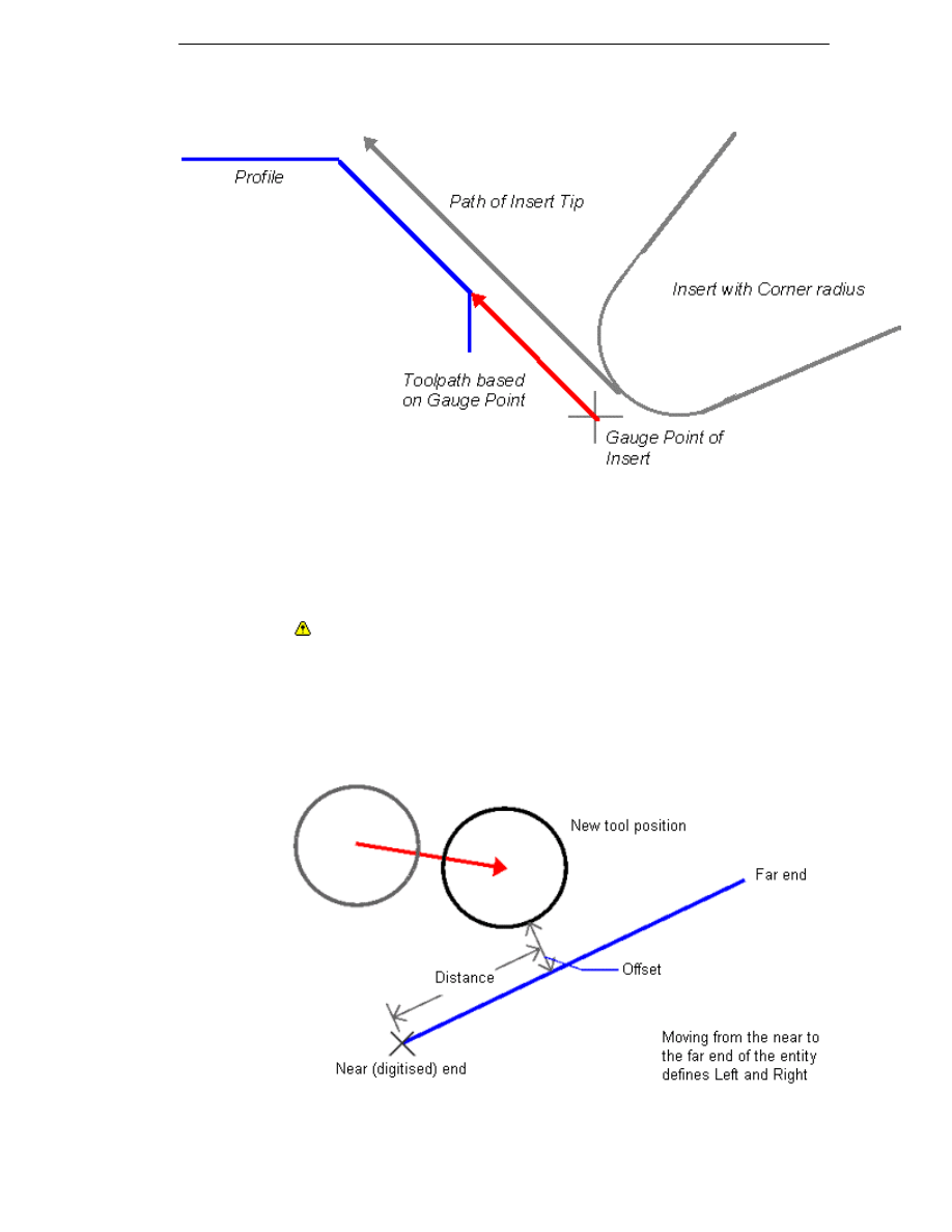
You may encounter a problem when cutting a chamfer with a radiused tool.
Normally the Gauge Point of the tool insert is driven along the geometry and
therefore the tool does not cut the correct profile.
44
EdgeCAM Manufacture - User Guide
This example shows that a toolpath based on the Gauge Point misses the
profile geometry:
The solution is to use the Move menu commands Relative, Relative Two or
Constrained with Pathtrace Compensation selected. These cycles calculate
the real position for the tool and place the tool correctly.
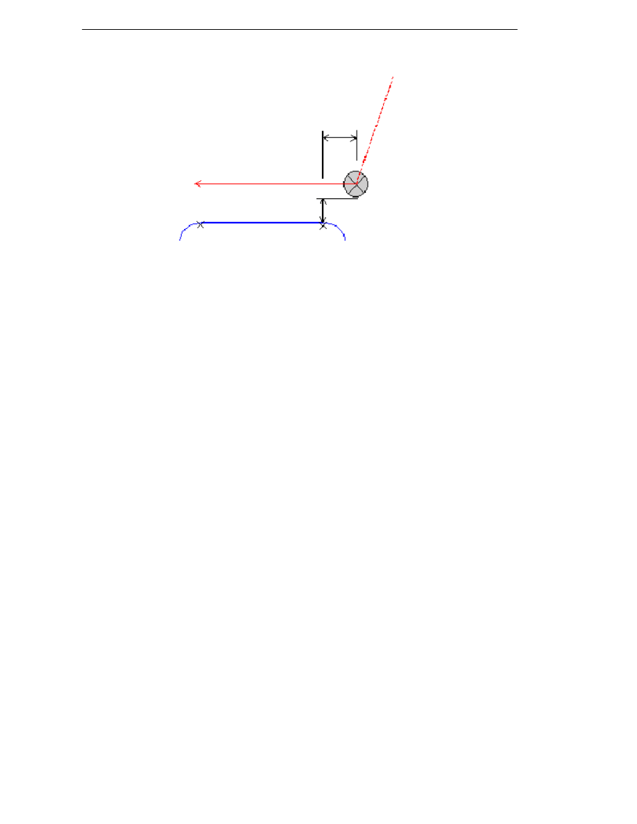
Moving Relative to an Entity
Milling and Turning environment only
Use the Relative (Move menu) command to position the tool with respect to a
selected entity.
In this example a tool has been moved at the Feedrate relative to a line
entity, with the parameters Distance and Offset specified, and the Side
parameter = Left.
45
Manufacturing Basics
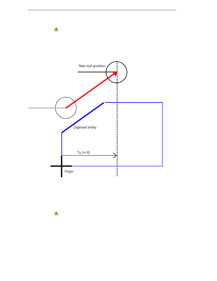
Moving Constrained by Entities
Milling and Turning environment only
Use the Constrained (Move menu) command to move to a destination point,
choosing from a variety of ways to constrain this motion using another selected
entity.
This milling example shows a Constrained feed move, using the parameters
Method=Parallel to Entity and To X=10.
When using the Constrained command, the move type can be set to either
Feed or Rapid. Note, however, that for non-linear moves the output will
always be in Feed mode. Rapid moves will be subject to the same “dog leg”
restrictions that apply to all other rapid moves, depending on the
characteristics of the selected machine tool.
Moving Relative to Two Entities
Milling and Turning environment only
Use the Relative Two (Move menu) command to move the tool relative to two
other selected entities. The First and Second tabs display the movement
parameters relative to the first and second entities respectively.
Otherwise, Relative Two uses the same parameters as the other move
commands, but with an important exception – the side of an entity nearest to
the tool is defined by which side you digitised the entity.
46

EdgeCAM Manufacture - User Guide
Selecting a Cycle
Once you have selected a tool and possibly used a rapid move to bring the
tool closer to the work, you are ready to select a machining cycle.
You can find all machining cycles permitted by the Code Generator file
selected for the machining sequence, and the current tool, under the Cycles
menu.
Individual buttons provide another method of selecting the appropriate cycle
(which of these are displayed on the toolbar is also determined by the
machining sequence and the current tool).
Finishing a Command
The help refers to the action ‘Perform a Finish’ when describing how to use
certain commands. In EdgeCAM, selecting the right hand mouse button will
finish a command.
Alternatively, selecting the Enter/Return key will also finish the command.
There is also an icon that can be added to your Toolbars. To add the icon,
select Toolbars (View menu), and select the Input Options Toolbar from
the list displayed on the Commands Tab.
The
icon can be added to any Toolbar by selecting it with the left hand
mouse button and dragging it on to a Toolbar.
47
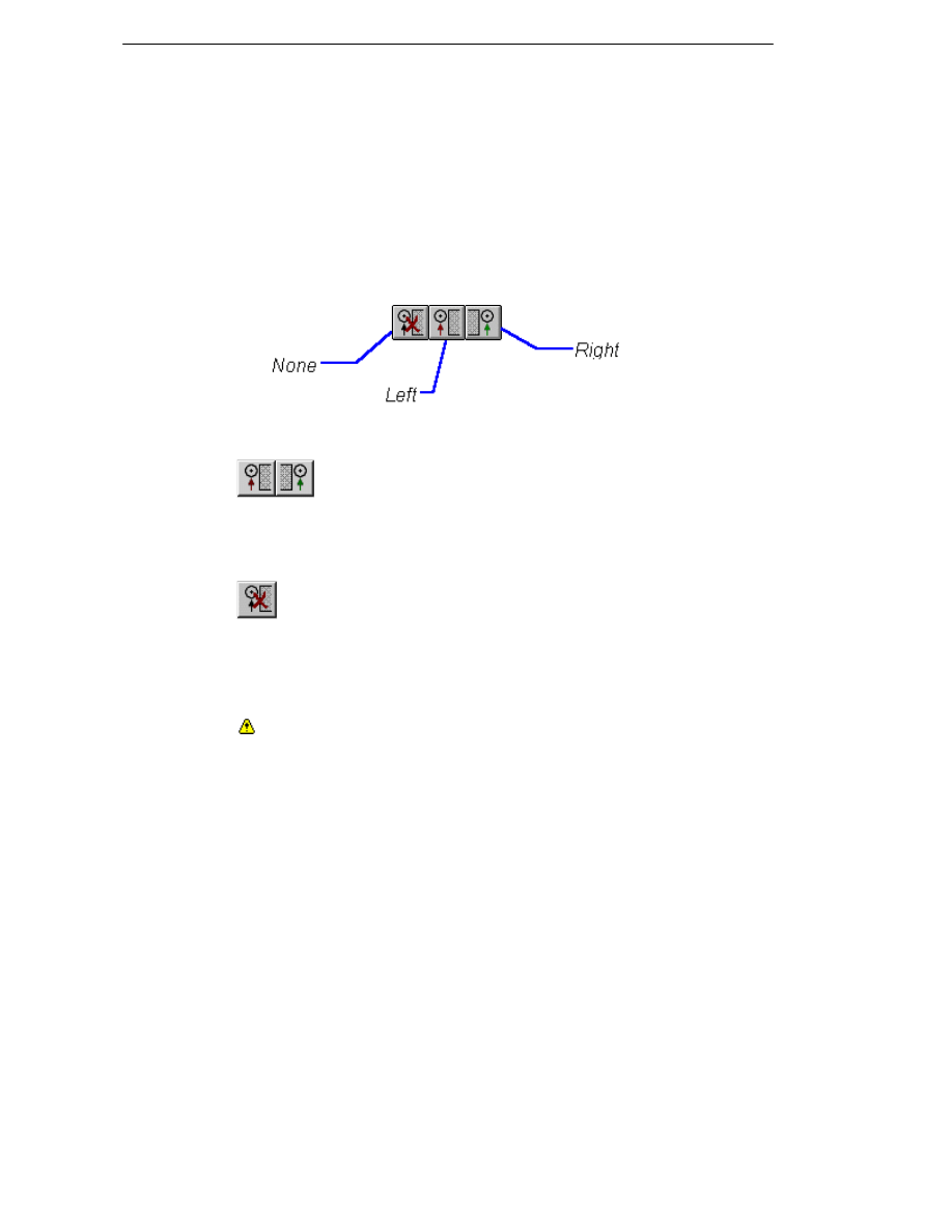
Manufacturing Basics
Using Cutter Compensation
Using Cutter Compensation in Milling Cycles
EdgeCAM provides a powerful tool radius offset calculation. Many machine tool
controllers also have a tool radius compensation facility, so when using the
Profile (Cycles menu) command you need to consider which method will work
best for you.
The Radius Compensation (Tooling menu) command or buttons:
allow you to select the offset facility (the Tooling toolbar must be selected
using Toolbars (View menu) to see these buttons).
If the Left or Right compensation buttons have been selected,
compensation remains on until the Off or the other compensation button is
selected. The compensation is further modified by the choice made in the
Compensation parameter for a cycle. This can be either Pathtrace or
Controller compensation.
If no compensation is applied, the CNC output is based purely on the
centreline toolpath. This button also switches off the current compensation
setting.
Note in using radius compensation in profile cycles
If mill type, profile side and radius compensation side are incompatible, a
warning message is displayed. When regenerating parts from previous
versions of EdgeCAM that were defined incorrectly, compensation side
overrides the other parameters. This may cause the profile side to be reversed.
See Also
Using No Compensation
Using Controller Compensation
Using Pathtrace Compensation.
48

EdgeCAM Manufacture - User Guide
Using Wire Compensation
EdgeCAM provides a powerful wire radius offset calculation. Many machine
tool controllers also have a wire radius compensation facility, so when using
the Machine Design (Cycles menu) command you need to consider which
method will work best for you.
The combination of the Radius Compensation and Compensation
parameters in the Machine Design and 2D Profile (Cycles menu) cycles
determines what information is to be output when you generate the CNC
code from your machining sequence:
Radius Compensation
Compensation
Pathtrace
Controller
None
Toolpath co-ordinates are
to be output.
Recommended.
Design Intent co-ordinates to
be output.
Not recommended.
Left/Right
Toolpath co-ordinates are
Design Intent co-ordinates
to be output, but the tool is are to be output, but the tool
instructed to use the
is instructed to use the
contents of an offset store. contents of an offset store.
Not recommended, as this
changes the actual size of
the final component.
Recommended, especially
where many different wire
diameters may be used.
Note that Radius Compensation is also available as a command from the Cycles
menu.
See Also
Using No Compensation
Using Controller Compensation
Using Pathtrace Compensation
49
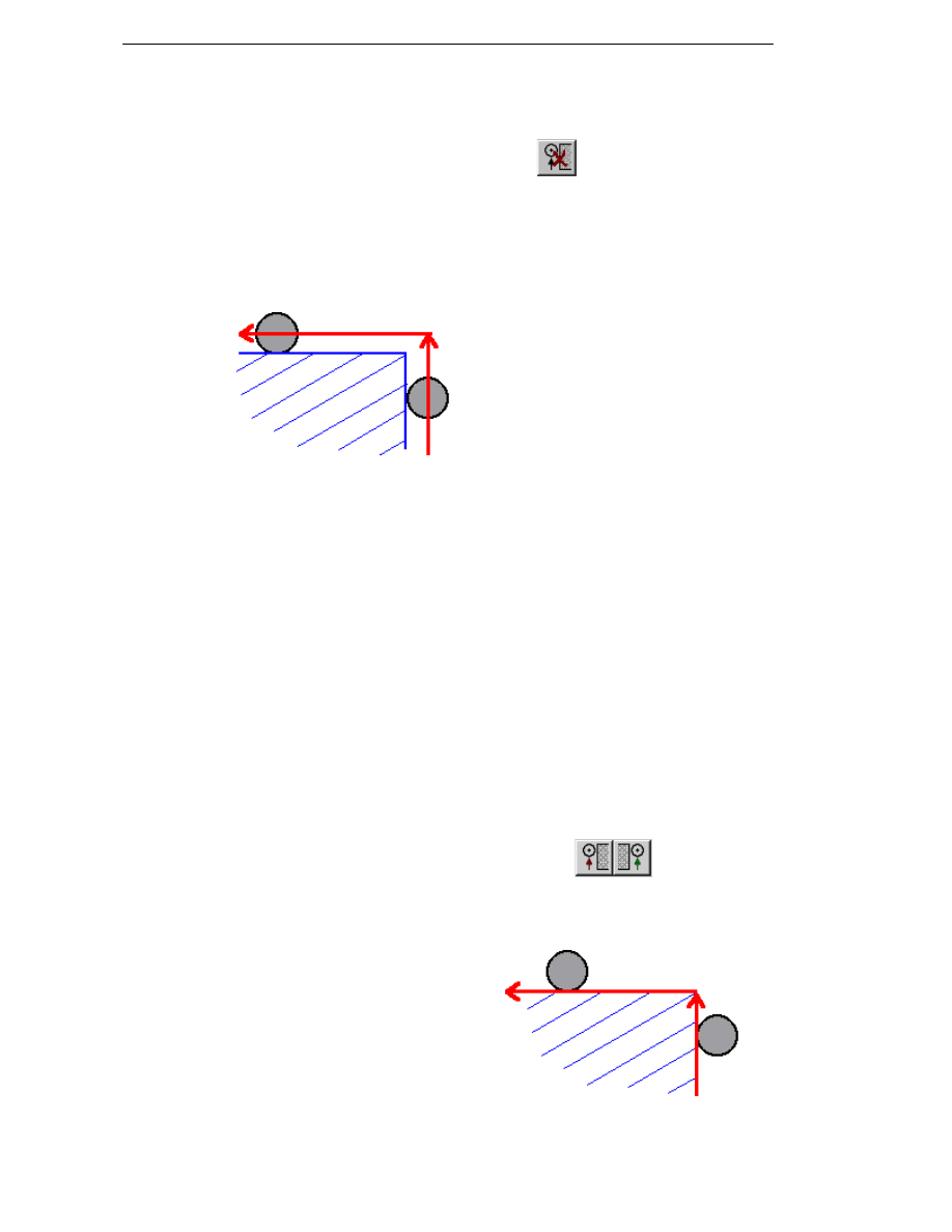
Manufacturing Basics
Using No Compensation
Radius Compensation
None
Compensation
Pathtrace
CNC output path
Tool/wire centreline
If no compensation is applied, the CNC output is based purely on the
centreline toolpath.
The advantages of this method of output are:
The tool/wire does not need a run-in onto the profile.
The toolpath displayed on screen is an accurate representation of the
output.
Corner Type parameters are supported.
The disadvantages of this method are:
The milling tool cannot be compensated for wear, therefore the part could
be cut over- or under-size.
CNC code is not as readable as it represents the centre of the cutter
rather than the geometry.
Using Controller Compensation
Radius Compensation
Left/Right
Compensation
Controller
CNC output path
Geometry or Design Intent
The CNC output is based on the
geometry of the profile or the
design intent. The controller
compensates for the radius of the
milling cutter/wire by using an
offset store within the control.
50
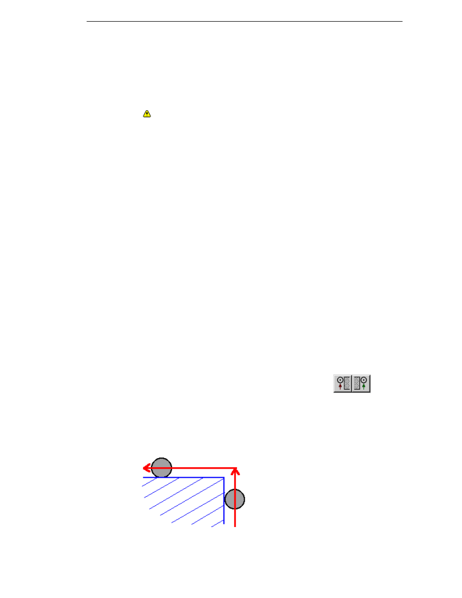
EdgeCAM Manufacture - User Guide
Notes in Using Controller Compensation in Milling
When the radius of the corner equals the tool radius, the shape of the
output corner is the same as the Corner Type parameter selected in the
cycle.
Profile cycles create a "back offset" NC path allowing for the tool radius.
The compensated toolpath is only displayed in Manufacture and resides
on the same layer as the toolpath.
Please note that compensation should only ever be applied in Profile
cycles.
The advantages of controller compensation are:
CNC code can be read more easily as the code represents the part.
The milling tool’s size can be altered to allow for tool wear.
The disadvantages of this method are:
Most controllers require the compensation code to be applied under strict
rules. These rules can vary between controllers. See your controller
handbook for details.
Controllers normally need a run-in of at least the radius of the cutter/wire,
but you may not have sufficient room around the part.
EdgeCAM’s Pathtrace compensation is superior to most controllers.
On external corners, if the Corner Type parameter is set to Round, this
will be ignored as it is not part of the geometry (milling environment).
The toolpath displayed on screen is not an accurate representation of the
output.
Using Pathtrace Compensation
Radius Compensation
Left/Right
Compensation
Pathtrace
CNC output path
Tool/wire centreline
The CNC output is based on the tool/wire centreline.
The controller compensates for the radius of the cutter/wire by using an offset
store within the control. The operator must set this offset store to zero prior to
running the program.
51
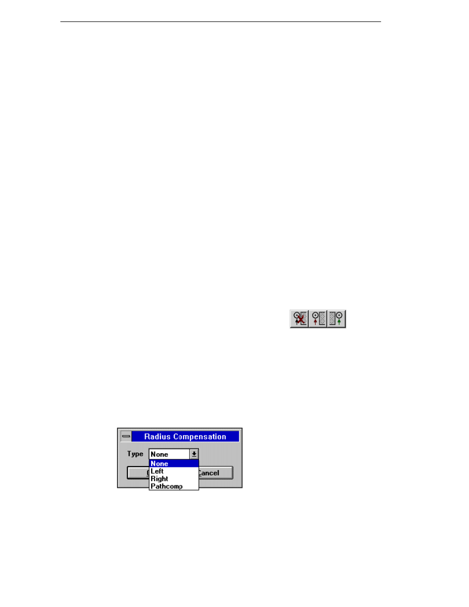
Manufacturing Basics
To adjust for tool wear in the milling environment, the operator must change
the offset store value by the difference between the true tool diameter and the
programmed tool diameter.
The advantages of this method of output are:
The milling tool’s size can be altered to allow for tool wear.
EdgeCAM’s Pathtrace compensation is superior to most controllers.
The toolpath displayed on screen is an accurate representation of the
output.
The controller does not need a run-in (as the radius of the cutter in the
offset store is set to zero), therefore the controller does not need a
compensation move.
Corner Type parameters are supported.
The disadvantage of this method is:
CNC code is not as readable as it represents the centre of the cutter
rather than the geometry.
Using Cutter Compensation in Turning
Cycles
EdgeCAM contains a powerful tool offset calculation facility for Turning
cycles. Many machine tool controllers also have a tool nose radius
compensation facility, so consider which method will work best for you. The
Radius Compensation (Tooling menu) command or
buttons allow you to select the offset facility (the Tooling toolbar must be
selected using Toolbars (View menu) to see these buttons).
Why use compensation at all? In this example the set point of a tool nose is
taken from the two edges of the radius. This means that the tool is driven by
the bottom left hand corner of the nose. If this point is programmed round a
profile, material can be left on or undercut when the tool travels at an angle,
producing an inaccurate part.
Using Pathtrace Compensation
This is applied using the Radius Compensation (Tooling menu) command:
Pathcomp
Turning Centres are usually limited to simple forms of compensation for
turning tools. EdgeCAM provides an extensive facility to compensate for the
tool geometry. Selecting Pathcomp causes the output tool path to be
readjusted to cater for tool geometry. This is in effect until cancelled.
52

EdgeCAM Manufacture - User Guide
Using Controller Compensation
The tool radius compensation facility on machine tool controls gives the
considerable advantage of allowing the operator to adjust for tool wear and
component deflection (caused by cutting forces).
Controller compensation is applied with using the Radius Compensation
(Tooling menu) or
buttons:
Left & Right
Applies controller compensation. In the case of Fanuc-like controllers, G41 &
G42 are inserted into the CNC code.
When controller compensation is applied, the programmed tool path is output
with respect to the tool set point, and it is assumed that the CNC controller is
compensating for the Tool Nose Radius. This mode requires that that controller
offset registers and tool types are defined correctly. Refer to your controller
manual for details.
None
Cancels controller compensation. In the case of Fanuc-like controllers, G40 is
inserted into the CNC code. This is the default condition.
53
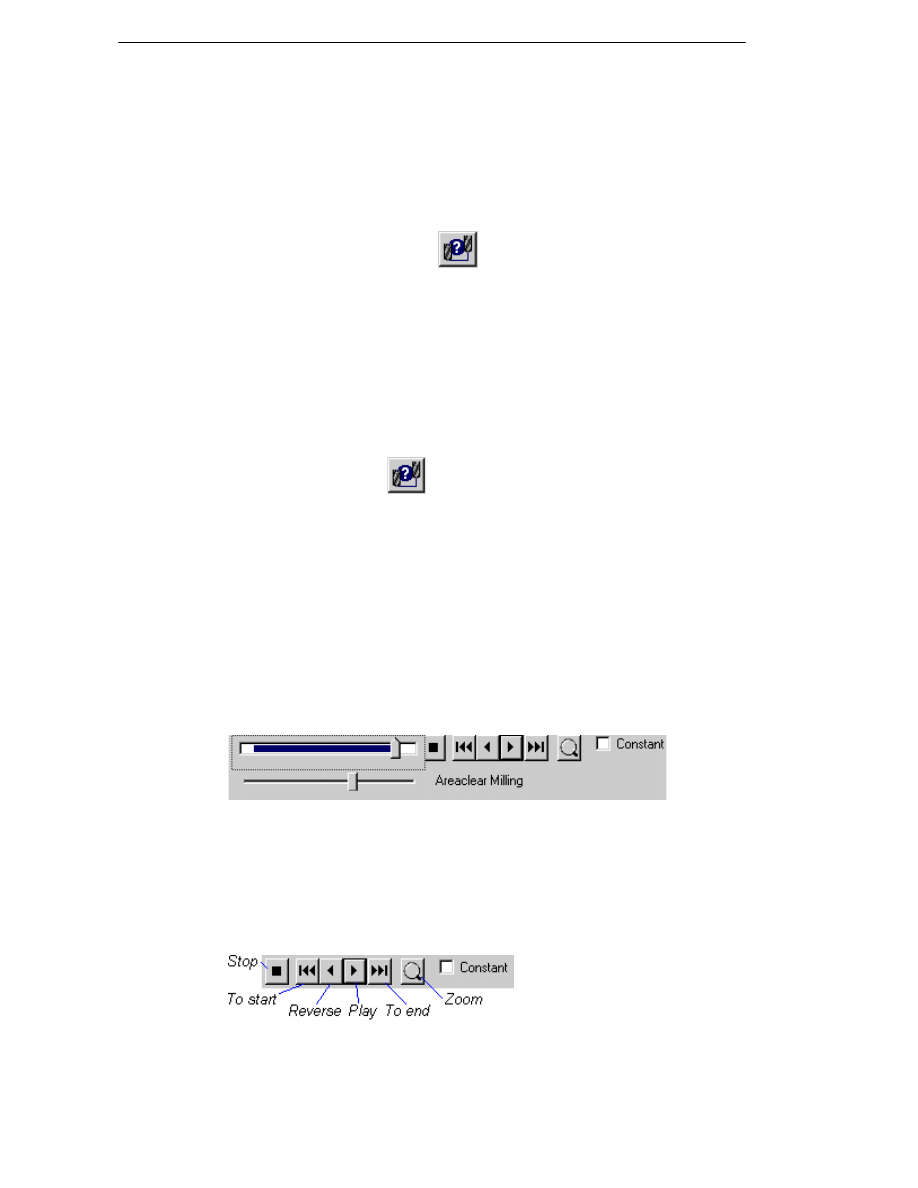
Manufacturing Basics
Displaying Toolpaths
You can use these methods to control how toolpaths appear on the graphics
screen:
Set the Colour parameter when selecting a tool. This determines the
colour of the tool/wire and all toolpaths created using it.*
Use the Mode (View menu)
command.
Switch on the Simulation toolbar.
*You can also specify a different colour for your rapid moves. Select the
Colours (Options menu) command and set the Rapids & Normals parameter.
Controlling the Toolpath Mode
The Mode (View menu)
command controls how tool motion is displayed
on the screen. You can restrict the simulation to only cover specific instructions
in the instruction list and control the speed of tool/wire motion.
Simulating Tool Movement
Once a cycle that moves the tool/wire has been fully defined, the system
displays a simulated tool/wire in the graphics screen area, moving along the
toolpath generated by the cycle. This is controlled using the Simulation
toolbar:
The top slider shows the progress of the simulation throughout the instruction
list. The current cycle or command is displayed (‘Areaclear Milling’ in this
example). You can narrow the selection to a smaller portion off the instruction
list by dragging the slider while holding down the Shift key, then click Zoom.
Click Zoom again to return to the entire instruction list.
Control the simulation using these buttons:
You can control the speed of the simulation by moving the bottom slider, left to
slow down and right to speed up.
54
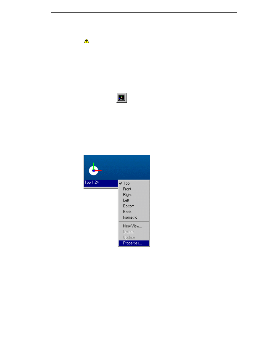
EdgeCAM Manufacture - User Guide
Check the Constant box to set the simulated tool/wire to move at a fixed
rate. Otherwise it will move at a rate proportional to the rates generated for
the cycle.
Please note that the simulation of toolpaths in Four Axis Turning cycles is
only correct when Constant is OFF.
Using the Stop button halts the simulation for the current tool only.
To switch on the Simulation toolbar
Select Simulation from the Status Bar (View menu) command, OR
Click on the
Simulation button on the Display toolbar.
Displaying Solid Models
A simple way of displaying solid models is to make sure you have checked
the GLview option under the View menu.
1. Right click on the view status bar and select Properties.
2. Choose the Rendered option from the Display parameter on the
General tab.
55

Manufacturing Basics
56

EdgeCAM Manufacture - User Guide
Editing Instructions in the Browser
E
DITING
I
NSTRUCTIONS
...................................................................................57
C
OMBINING
C
OMPONENTS AND
S
EQUENCES
....................................................59
Preparation of Base Parts .........................................................................60
Insert and Merge in Use ............................................................................60
Notes on Inserting and Merging Sequences .............................................61
I
NSERTING
S
EQUENCES
...................................................................................62
M
ERGING
S
EQUENCES
....................................................................................63
R
E
-
ORDERING THE
M
ACHINING
I
NSTRUCTIONS IN A
S
EQUENCE
.........................64
Merging Hole Cycles .................................................................................64
Rationalising by Tool .................................................................................65
Rationalising by Priority.............................................................................66
Rationalising by CPL/Index .......................................................................67
Example 1 – Rationalise by Tool Position .............................................................68
Example 2 – Rationalise by CPL ...........................................................................69
Example 3 – Rationalise by Tool Position and then CPL ......................................70
M
ERGING
H
OLE
C
YCLES
..................................................................................71
Setting Parameters before Merging Hole Cycles ......................................71
Depth Parameters in Merged Cycles ....................................................................72
Using the Merge Hole Cycles Command ..................................................72
Merging Hole Cycles - Example ................................................................73
Merging into Multiple Cycles - Example ....................................................74
U
SING
I
NSTRUCTIONS
M
ENU
C
OMMANDS
.........................................................75
Choosing the Editing Options....................................................................76
Selecting from the Instruction List .............................................................77
Respecifying Co-ordinate Input .................................................................77
Editing Instructions
The browser window on the left-hand side of the EdgeCAM screen shows all
associated machining sequences and instructions related to the current part.
By default, the instructions in the Browser window are numbered as this can
be useful when a part has a large number of similar instructions. To display
the instructions without numbers, please ensure that the Number
Instructions option on the Toolpath tab of the Preferences (Options menu)
dialog is unchecked.
If a Sort Priority has been assigned to a toolchange this priority will be
displayed in the Instructions Browser to the right of the instruction number.
57
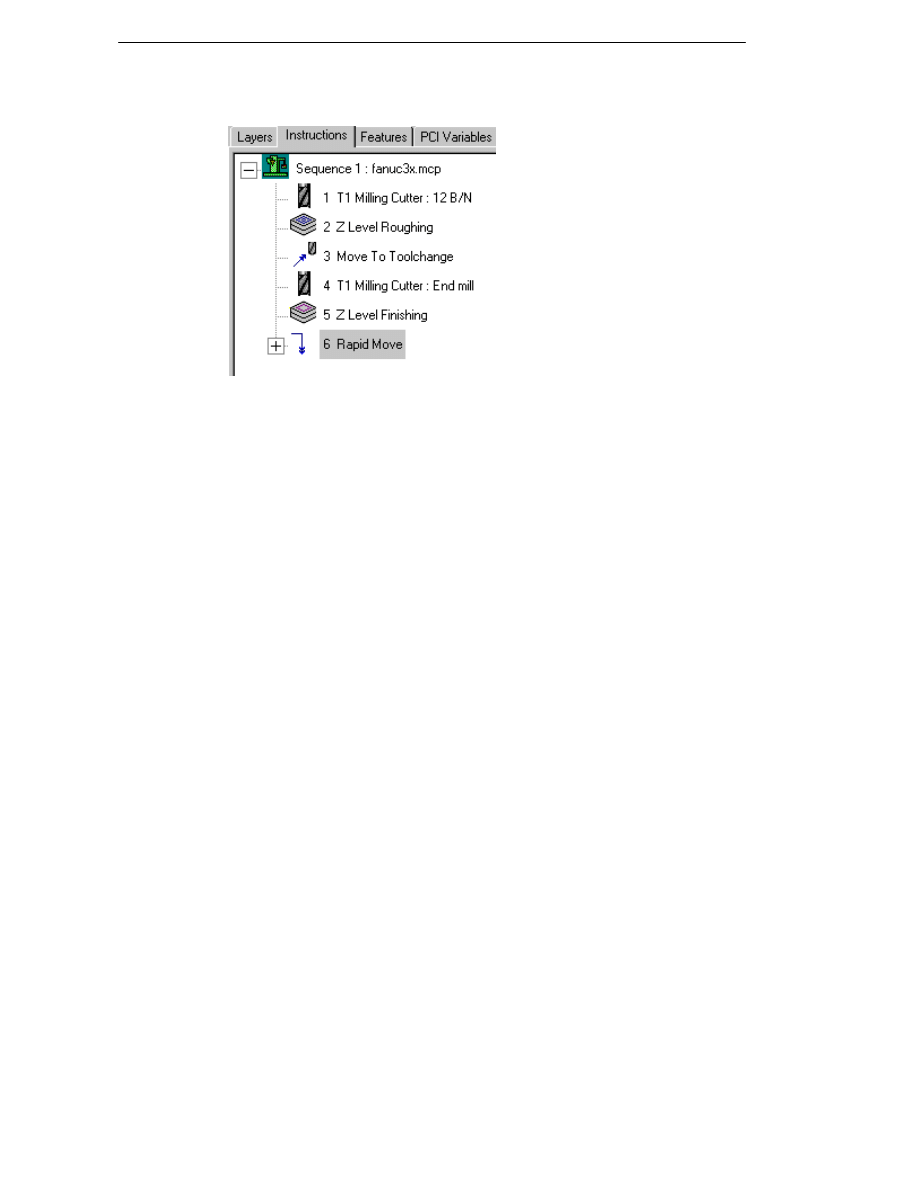
Editing Instructions
As explained under Browsing the Instruction List, you can use this window to
edit the current instruction list.
Notes
Only commands that are included in the instruction list can be edited,
moved or deleted.
Editing one or more sub-instructions within an Operation breaks the
Operation down into its constituent cycles.
If you edit an Index (Move menu) command, all subsequent commands
may be invalidated.
Once the instruction list has been changed, EdgeCAM recalculates the
toolpath according to the new geometry.
In the milling and turning environment, the Merge Sequences
(Instructions menu) command allows you to merge two or more
sequences into one by appending the instructions in the second and
subsequent sequences to those in the current sequence. See Merging
Sequences.
In the milling environment, the Rationalise (Instructions menu)
command allows you to re-order the instructions in a single sequence to
rationalise the NC file by one or more criteria. See Re-ordering the
Machining Instructions in a Sequence
58

EdgeCAM Manufacture - User Guide
Combining Components and Sequences
It is possible to, optionally, insert sequences when inserting a part as a
component into another part. It is also possible to then merge the separate
sequences into a single sequence and to rationalise that sequence by tool,
index angle or CPL. Whilst these three functions have been designed to work
together, primarily in a multiplane milling environment, they may also be used
separately and also in 3 axis milling or in turning.
When merging sequences in multiplane milling the Profile cycle is liable to
corruption. To ensure that inserting and merging function correctly, profiles
must be created in a defined view, not in "dynamic".
The most common use for these features is in loading components onto a
machine with rotary axes so that a combination of parts or multiples of the
same part can be machined.
This use of Insert and Merge is the most complex and is described below in
some detail. The principles laid down here, and the techniques suggested,
can also be applied in other circumstances such as multiple parts laid on a
flat machine bed or sub-programs merged into a single final program for a
turning application. Please note that since datum shifting is not supported in
turning only sequences utilizing common initial and machine datum points can
be successfully merged.
The use of both Insert and Merge offers considerable flexibility in approach
but for maximum ease of use it is suggested that you follow a few simple
guidelines:
1. For each machine tool, a "Base Part" containing the machine's basic set up
and configuration should be created. Common use fixtures such as a
machined cube should be incorporated. This part should contain a single
sequence with the Code Generator reference and with home/toolchange
positions, initial plane, initial CPL and machine datum points correctly
configured.
When you merge sequences, the current sequence is
copied to form the new sequence. For this reason it is important that your
current sequence has been created correctly for your machine tool,
especially with regard to the machine datum and initial CPL.
2. Suitable location or mounting positions should be created as CPLs on the
cube faces.
3. Parts to be inserted as components should always be created with a
"location" CPL in position to enable easy placement on the machine. If
fixtures are used they may be incorporated into the component with the
"location" CPL on the back face of the fixture.
4. When components are inserted the target part will, inevitably, build up a
large number of CPLs. Whilst EdgeCAM will ensure that there are no name
clashes, you may find it helpful to use the "Name Prefix" field in the Insert
Component dialog. This enables all CPLs and layers relating to a particular
component to be identified.
It is strongly recommended to use the following suggested method for use of
Insert and Merge in a multiplane environment. In other environments these
procedures can be adapted accordingly.
59

Editing Instructions
Preparation of Base Parts
1. Create a base part for each machine tool with cube or tombstone etc. in
place and with the machine datum (centre of primary rotation) marked.
2. If common location points on the faces of the cube are to be used, create
CPLs at those positions.
3. Create an empty sequence with the required code generator, initial CPL
and machine tool datum (centre of rotation). Check that
home/toolchanges and initial plane entries are correct.
4. Save this as a "Base Part" for that machine. Make a backup copy as a
guard against accidental over-writing.
5. When creating component parts to be used on this machine always create
a CPL that matches the position of the location points. Giving this CPL a
common name in all such parts makes life easier, e.g. "Location".
6. If fixtures are to be used as separate .ppf files give each a CPL for location
of the component and a CPL for positioning the fixture on the cube.
Standardise the CPL names but remember they will be modified on
insertion.
When you merge sequences, the current sequence is copied to form the
new sequence. For this reason it is important that your current sequence has
been created correctly for your machine tool, especially with regard to the
machine datum and initial CPL.
Insert and Merge in Use
1. Load base part and save as required combined part name.
2. Insert component(s) as required, placing location CPL on mounting
CPLs.
3. Switch to manufacture.
4. If necessary, edit sequences to change to the correct Code Generator.
5. Select base sequence and pick "Merge Sequences" from browser menu
or Instructions menu.
6. Select sequences required by moving them from left panel to right. Fill in
new sequence name etc. and click OK.
7. Check through the newly created sequence and remove any unwanted
instructions. Carefully check all clearances etc, especially when indexing.
60

EdgeCAM Manufacture - User Guide
Notes on Inserting and Merging Sequences
Realignment of Toolpaths
Where regeneration of a sequence results in realignment of the toolpath to suit
machine tool axes, any angles and free digitise positions used in the
instructions will also be realigned and measured from the machine tool axes.
This means that such angles and positions may move relative to the
component. This is most likely to occur when components are inserted at an
angle to the target CPL.
If a rapid or feed move position is considered critical and it is intended to rotate
the part in this way then you should create a geometric point in the required
position and make an entity digitise for the move. If angles, such as lace cycle
angle or thread mill start/end angles, are critical then they must be re-adjusted
after the realignment.
Post Processors
All sequences must use the same code generator when merging.
The success of insert and merge operations is utterly dependent on the
compatibility of the code generator files in use and the machine tool
requirements. You must ensure that you have set your Code Generator files
correctly for all possible instances of Index and Datum Shift commands.
Inserted sequences retain their machine datum. When sequences are merged
the current or base sequence machine datum is used.
Safe Indexing
It is vital that all index moves be performed with the tool at a safe height. You
must ensure that individual parts are programmed with this in mind and that
any merged sequences are thoroughly checked in an appropriate view to
ensure safety.
The toolchange heights and initial plane value should reflect actual machine
tool requirements.
All index commands in parts to be inserted as components should be to
named CPLs (Position To Name). The way in which indexing by angle
handles datum positions may not give the required result.
Component Prefixes
When inserting multiple components into a part, EdgeCAM will rename CPLs,
layers, sequences etc. with an appended number to ensure that the integrity of
each component is maintained. This can become confusing and it is
recommended to specify a name prefix for each component inserted so that the
CPLs and layers relevant to individual components are easily identifiable.
Rotary Milling
The Insert Component and Merge Sequence commands are not supported in
rotary milling.
Wire Erosion
Merging Sequences is restricted to the milling and turning environment and
will not appear in the wire manufacture mode.
PCI
PCI command recording and playback is not supported for merge sequences.
Turning
Datum shift is not supported by EdgeCAM for turning parts. For this reason
all inserted components with sequences must use the same target CPL.
61
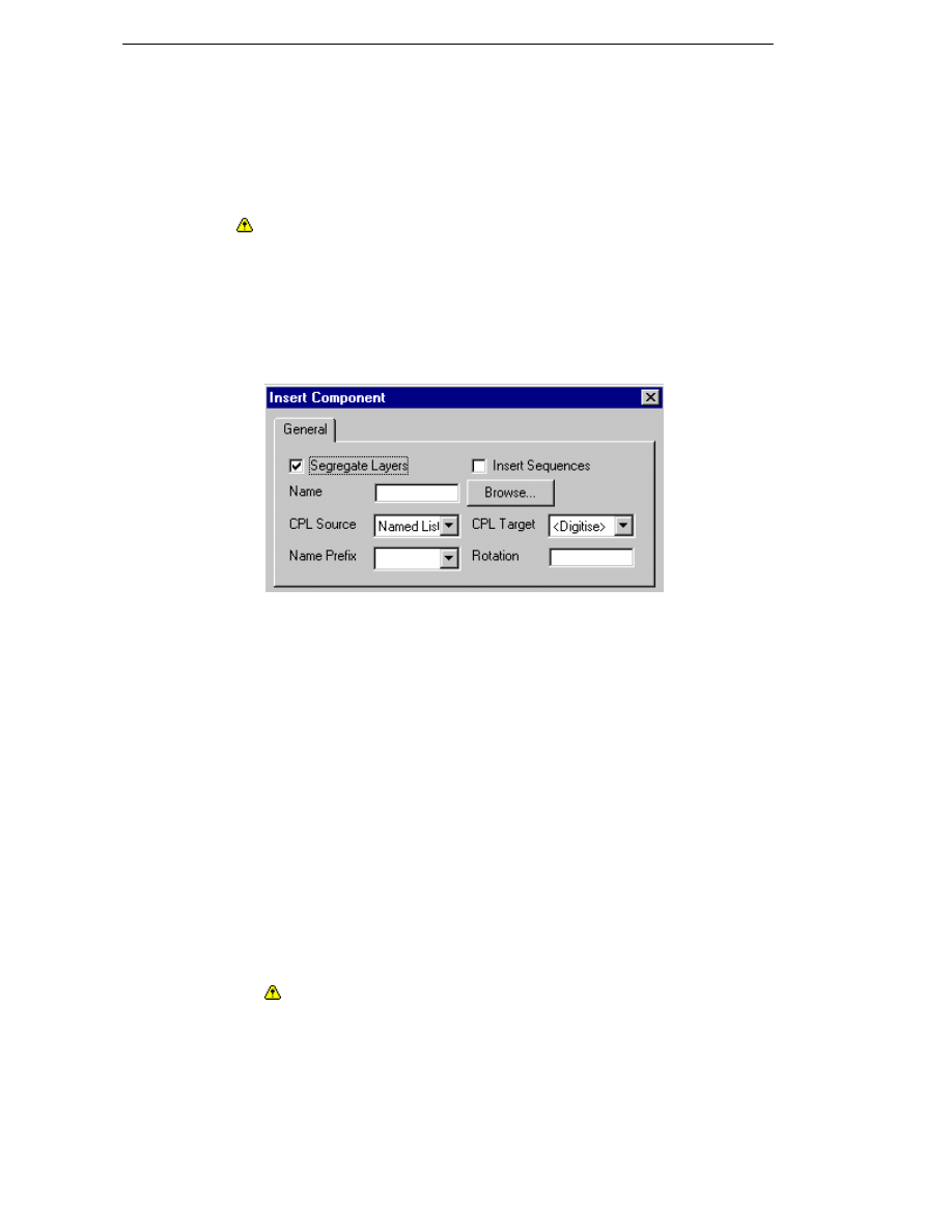
Editing Instructions
Inserting Sequences
Requires the Multiplane Machining licence
The Insert, Component (File menu) command allows you to insert a
component and its machining sequences into the active part. Please note
that sequences are not inserted if their part units are different.
When merging sequences in multiplane milling the Profile cycle is liable to
corruption. To ensure that inserting and merging function correctly, profiles
must be created in a defined view, not in "dynamic".
To insert a component with machining sequences
1. Select the Insert, Component (File menu) command. The dialog
offers the following commands:
2. Check the Segregate Layers option if you want all entities to remain on
their existing layers. The layers will be renamed, with the name consisting
of the inserted part name followed by the original layer and a number
representing the instance of insertion of that part (1,2,3 etc.). If this box
has not been checked, part name and incremental numbering will not be
used and all entities from a particular layer in the source part will be
placed on the same layer in the target part.
3. Check the Insert Sequences option.
4. Enter or Browse for the Name of the .ppf part file to be inserted.
5. Specify the Target and Source CPLs.
CPL Source – Nominate the CPL in the named part.This determines how
the geometry is to be inserted into the current part. Select from Named List
or Digitise a user-defined CPL.
CPL Target – Nominate the CPL onto which to insert the component.
Select from Digitise or a list of available CPLs in the current environment. If
you choose Digitise, you are prompted to digitise the appropriate CPL
marker.
Datum shift is not supported by EdgeCAM for turning parts. All
inserted components with sequences must use the same target CPL.
62
EdgeCAM Manufacture - User Guide
6. When components are inserted the target part will build up a large
number of CPLs. The Name Prefix option enables you to easily identify
all CPLs and layers relating to a particular component.
7. Enter any required Rotation about the Z axis of the target CPL. Centre of
rotation will be that of the target part not that of the source part(s).
8. Click OK.
Note: The 'Undo' functionality is not supported when inserting
components with sequences.
Merging Sequences
Only available in the milling and turning environment. Please note that this
function is not supported by rotary milling.
The Merge Sequences command allows you to merge two or more
sequences into one by appending the instructions in the second and
subsequent sequences to those in the current sequence. For more detailed
information on common use and recommended methods, please refer to
Combining Components and Sequences.
All sequences to be merged must use the same Code Generator.
When merging sequences in multiplane milling the Profile cycle is liable to
corruption. To ensure that inserting and merging function correctly, profiles
must be created in a defined view, not in "dynamic".
When you merge sequences, the current sequence is copied to form the
new sequence. For this reason it is important that your current sequence has
been created correctly for your machine tool, especially with regard to the
machine datum and initial CPL.
To merge sequences
1. Highlight a base sequence in the browser and call up the Merge
Sequences command, either via the context menu (right-hand mouse
click) or the Instructions menu. This will open the Merge Sequence
dialog.
2. The Current Sequence field specifies the name of the base sequence.
When merging, the current sequence is copied to a new name and all
other selected sequences are appended in order.
3. Specify the name for the new (merged) sequence in the Description
field. By default, the name of the new sequence is created by appending
.1, .2 etc to the name of the current sequence.
4. Job file names allocated to the sequences being merged will not be
carried over to the new (merged) sequence. If you want to allocate a job
file to this sequence you must enter the required name in the Job Name
field.
5. Select sequences required by moving them from the list of Available
Sequences on the left to the list of Selected Sequences on the right. You
can do this by simply highlighting the required sequence(s) and pressing
the single arrow. The double arrow allows you to move all sequences to
the right panel. To change the order in which sequences are merged,
select one or more in the right-hand panel and use the arrows on the
extreme right to change their relative positions. Sequences will be merged
in the order shown when the command is executed.
63

Editing Instructions
6. Specify the required Datum Type. You must take into account the
requirements of your machine tool when making this choice. Also bear in
mind any limit on the number of definable datum points when planning a
merged sequence.
7. Check the Remove Tool Positions option to set all tool positions to
blank in the merged sequence. You will need to re-specify these
parameters for all toolchanges by editing the appropriate toolchange dialog.
If this option is not checked, it is assumed that you are happy with the
sequences and no changes will be made. Please note that option is only
offered once for each merge commend and there will be no further checks
for compatibility.
8. Click OK.
Note: The 'Undo' functionality is not supported when merging sequences.
Re-ordering the Machining Instructions in a
Sequence
Only available in the milling environment.
The Rationalise (Instructions menu) command allows you to re-order the
instructions in a single sequence to rationalise the NC file by one or more
criteria.
You can choose between sorting the instructions by Tool (default setting),
CPL or Index.
Rationalisation will always be applied to the currently selected sequence.
When re-ordering by several criteria sorting must be done in the reverse
order. Also see Example 3.
The Undo command is not supported by this function. The sorted
sequence is created as a new sequence and can easily be deleted, if not
required. The new ‘duplicate’ machining sequence will automatically be
renamed by appending ‘.1’.The original sequence will not be changed by
the rationalisation process. Once you are satisfied with the re-ordered
sequence you can delete the original sequence.
Sequences containing instructions in “Matrix Mode” cannot be
rationalised.
Merging Hole Cycles
When sequences are rationalised, a number of cycles are frequently grouped
together for machining by a single tool. In the case of hole cycles this gives rise
to a canned cycle (G81 etc) in the NC file for each EdgeCAM cycle instruction.
The Merge Hole Cycle option on the Rationalise Sequence
(Instructions menu) dialog enables you to group such instructions into a
single cycle so that multiple, identical holes may be drilled with one G81
canned cycle.
Please note that this option is only available when
rationalise is by tool. Also see Merging Hole Cycles.
Ensure that you have carefully checked the re-ordered sequence before
deleting the old one and using the new one.
64

EdgeCAM Manufacture - User Guide
Rationalising by Tool
Instructions will be selected by turret position ONLY. If different tools have
been assigned to the same position the one assigned first will be used. A
warning will be given if a different tool type, diameter(s), corner radius, angle
or description is encountered on a previously used turret position.
The sorting mechanism will work through the sequence sorting by tool as the
first instance of use is found. If a tool is required to be exempted from sorting
you will have to edit it to another turret position number and then reset it after
the sorting is complete.
A check will be made to ensure that a turret position has been specified for all
tools. If not, a warning will be given and the faulty toolchange indicated in the
browser.
Changes to Tlo offset register for a given tool position will be maintained. If
this situation is encountered a toolchange command will be used to change
the value. No other tool parameters will be changed and there will be a retract
to safe height before the toolchange instead of a return to toolchange position.
All instructions using the tool will be moved with it. Any necessary index or
datum shift instructions to give correct orientation from the preceding
instructions will be inserted.
Where groups of instructions are brought together by the rationalisation
process a move to safe Z will always be inserted. This will prevent the creation
of 3D rapid moves that could scrap the part or be a safety hazard. If required,
you can remove such moves afterwards.
Rationalise will insert retract moves to the Z of the toolchange position before
inserted index and datum shift instructions. Index commands will be inserted
with the “shortest” direction modifier set.
There are circumstances when sorting by tool in order of first use does not
give you the desired results. In this case, an alternative method of sorting by
tool can be used. See Rationalising by Priority.
When sequences are rationalised, a number of cycles are frequently
grouped together for machining by a single tool. In the case of hole cycles this
gives rise to a canned cycle (G81 etc) in the NC file for each EdgeCAM cycle
instruction. The Merge Hole Cycle option on the Rationalise Sequence
(Instructions menu) dialog enables you to group such instructions into a
single cycle so that multiple, identical holes may be drilled with one G81
canned cycle. Please note that this option is only available when rationalise is
by tool.
65

Editing Instructions
Rationalising by Priority
There are circumstances when sorting by tool in order of first use does not give
you the desired results. For some combinations of cycles this can, for example,
reverse the order of roughing and finishing, with dangerous results. To
overcome this scenario, you can assign a sort priority to each toolchange by
specifying a Sort Priority modifier on the More tab of the toolchange dialog.
Sorting will then be performed by order of first use within each priority group.
All tools with the same priority will be sorted by order of first use, followed by
those with the next priority and so on in ascending numerical order.
If a Sort Priority has been assigned to a toolchange this priority will be
displayed in the Instructions Browser to the right of the instruction number.
Usage Tips:
It is much easier to set the priority of tools in the individual part files when
developing the machining sequence before rationalising the merged
sequence. We would suggest that types of tools are given a pre-defined
number that relates to a type of operation.
For example:
100 = Roughing
200 = Semi roughing
300 = Semi finishing
400 = Finishing
500 = Centre Drill / Spot face
600 = Drilling
700 = Tapping / Reaming / Boring
When the merged sequence is rationalised the priority order will ensure that
all roughing is carried out before any semi-roughing and semi-roughing is
performed before any semi-finishing etc.
Any final changes to the tooling order can be achieved by adjusting the Sort
Priority after rationalisation.
For example you may wish to change the order of two roughing tools (both
have Priority 100) by changing the sort priority for one of them to 101 or 99.
Once all the final changes have been made run Rationalise by Tool again to
re-order the sequence.
66

EdgeCAM Manufacture - User Guide
Rationalising by CPL/Index
Sort by Index is ordering by resultant rotary axis positions. If two or more CPLs
result in the same rotary axis positions then the instructions associated with
them will be combined, e.g. the front face of a component on a cube might be
machined at the same time as side faces of components mounted on adjacent
sides. Datum changes will be retained by insertion of a datum shift command.
Sort by CPL works on CPL name only. Identical (rotary angle and datum
position) CPLs will be combined but CPLs having the same rotation but a
different datum will not.
When sorting by Index or CPL additional toolchanges with safe moves to the
toolchange position will be inserted as required. The data for these
toolchanges will be copied from that associated with the instructions in the
original sequence (including both turret position and Tlo number).
For the purpose of this operation, a “toolchange” is taken to mean the relevant
toolchange instruction together with its move to toolchange position and any
M-Functions that precede the toolchange (back to the preceding cycle
command or feed move).
For repeats of the first toolchange, the preceding M-Functions and move to
toolchange position will be taken from the next toolchange instruction. Where
groups of instructions are brought together by the rationalisation process a
move to safe Z will always be inserted. This will prevent the creation of 3D
rapid moves that could scrap the part or be a safety hazard. If required, you
can remove such moves afterwards.
Sort by Index or CPL will take account of both primary and secondary rotation
axes where both exist.
67

Editing Instructions
Example 1 – Rationalise by Tool Position
Original Sequence
Sort by Tool Position
Initial CPL 1
Tool 1
Instructions A
Z Safe
Index to CPL 2
Instructions B
Move to ToolChange
Tool 4
Instructions C
Move to ToolChange
Tool 3
Instructions D
Z Safe
Index to CPL 1
Instructions E
Z Safe
Index to CPL 2A (Same index position as CPL2)
Instructions F
Move to ToolChange
Tool 2
Instructions G
Move to ToolChange
Tool 7
Instructions H
Z Safe
Index to CPL1
Instructions I
Move to ToolChange
Tool 2
Instructions J
Return to Home
Initial CPL 1
Tool 1
Instructions A
Z Safe
Index to CPL 2
Instructions B
Move to ToolChange
Tool 4
Instructions C
Move to ToolChange
Tool 3
Instructions D
Z Safe
Index to CPL 1
Instructions E
Z Safe
Index to CPL 2
Instructions F
Move to ToolChange
Tool 2
Instructions G
Z Safe
Index to CPL 1
Instructions J
Move to ToolChange
Index to CPL 2
Tool 7
Instructions H
Z Safe
Index to CPL1
Instructions I
Return to Home
68

EdgeCAM Manufacture - User Guide
Example 2 – Rationalise by CPL
Original Sequence
Sort by CPL
Initial CPL 1
Tool 1
Instructions A
Z Safe
Index to CPL 2
Instructions B
Move to ToolChange
Tool 4
Instructions C
Move to ToolChange
Tool 3
Instructions D
Z Safe
Index to CPL 1
Instructions E
Z Safe
Index to CPL 2A (Same index position as CPL2)
Instructions F
Move to ToolChange
Tool 2
Instructions G
Move to ToolChange
Tool 7
Instructions H
Z Safe
Index to CPL1
Instructions I
Move to ToolChange
Tool 2
Instructions J
Return to Home
Initial CPL 1
Tool 1
Instructions A
Move to ToolChange
Tool 3
Instructions E
Move to ToolChange
Tool 7
Instructions I
Move to ToolChange
Tool 2
Instructions J
Move to ToolChange
Tool 1
Index to CPL 2
Instructions B
Move to ToolChange
Tool 4
Instructions C
Move to ToolChange
Tool 3
Instructions D
Z Safe
Instructions F
Move to ToolChange
Tool 2
Instructions G
Move to ToolChange
Tool 7
Instructions H
Return to Home
69

Editing Instructions
Example 3 – Rationalise by Tool Position and then CPL
Original Sequence
Sort by Tool Position and then CPL
*
Initial CPL 1
Tool 1
Instructions A
Z Safe
Index to CPL 2
Instructions B
Move to ToolChange
Tool 4
Instructions C
Move to ToolChange
Tool 3
Instructions D
Z Safe
Index to CPL 1
Instructions E
Z Safe
Index to CPL 2A (Same index position as CPL2)
Instructions F
Move to ToolChange
Tool 2
Instructions G
Move to ToolChange
Tool 7
Instructions H
Z Safe
Index to CPL1
Instructions I
Move to ToolChange
Tool 2
Instructions J
Return to Home
Initial CPL 1
Tool 1
Instructions A
Move to ToolChange
Tool 3
Instructions E
Move to ToolChange
Tool 2
Instructions J
Move to ToolChange
Tool 7
Instructions I
Move to ToolChange
Tool 1
Index to CPL 2
Instructions B
Tool 4
Instructions C
Move to ToolChange
Tool 3
Instructions D
Z Safe
Instructions F
Move to ToolChange
Tool 2
Instructions G
Move to ToolChange
Tool 7
Instructions H
Return to Home
*
Note that the sorting criteria were applied in reverse order, i.e. Sort by CPL (the “primary”
criterion) was the second on applied.
70

EdgeCAM Manufacture - User Guide
Merging Hole Cycles
When sequences are rationalised, a number of cycles are frequently grouped
together for machining by a single tool. In the case of hole cycles this gives rise
to a canned cycle (G81 etc) in the NC file for each EdgeCAM cycle instruction.
The Merge Hole Cycle option on the Rationalise Sequence (Instructions
menu) dialog enables you to group such instructions into a single cycle so
that multiple, identical holes may be drilled with one G81 canned cycle and
not many individual canned cycles each drilling one hole.
You can merge hole cycles if the following conditions are met:
the cycle parameters are equal or compatible (see Setting Parameters
before Merging Hole Cycles)
the cycles are adjacent except for rapid Z moves, repeat modal functions
(such as instruction 9 in the example) and self-cancelling pairs of modal
functions (e.g. Coolant Off followed by Coolant Flood)*
* Self-cancelling pairs of spindle and coolant instructions will be removed from
between cycles that are being merged. This action is controlled by the
instruction number (Code Generator macro number) and custom posts using
different macro numbers may produce unexpected results.
Where a number of cycles are to be merged and there are some intermediate
instructions that prevent merging into one cycle, the cycles will be merged into
multiple cycles separated by the appropriate commands (see example).
The Merge Hole Cycle command is only available for Code Generators
that support multilevel/multidepth drilling.
When using the Merge Hole Cycle command compatible cycles with
different Feature Name settings are not merged. For this reason, the Feature
Name modifier should be left blank if the hole cycles are to be merged.
You must ensure that merged cycles act in the required way and that the
toolpaths produced are safe and clear of any obstacles such as fixtures etc.
Setting Parameters before Merging Hole
Cycles
The following parameters must be identical in all affected cycles to allow a
merge of those cycles:
General tab* - Strategy, Plunge Feed, Speed, Dwell Time, Tap Cycle,
Longhand
Step tab - Cut Increment, Degression, Safe Distance
Entry tab - Tool Diameter, Entry Depth, Entry Feed
Filtering parameters will be ignored as they are used for data input control
rather than processing of the cycle.
*
If all of the cycles to be merged have the same Optimisation setting then
the new cycle will be optimised by that method. If cycles have different
optimisation the combined cycle is set to <none> and is not optimised. The
order of drilling will be as if cycles had never been optimised and thus the
toolpath may change.
71

Editing Instructions
Depth Parameters in Merged Cycles
If Level/Depth is constant for all merged cycles the Level/Depth field will be
set to that value. If the cycles contain coordinates at different levels or
require drilling to different depths the Multi Level and/or Multi Depth
checkboxes will be set automatically for the combined cycle. The Depth
and Level parameters will be stored for each hole in the cycle.
The clearance plane will be set at the highest Clearance value specified
in the merged cycles and intermediate retracts (except retracts to
toolchange Z).
Retract will be set to the highest Retract value within the merged cycles.
Using the Merge Hole Cycles Command
Before merging your hole cycles it is suggested that you follow a few simple
guidelines:
1. Ensure that the parameters for the cycles that are to be merged are
equal or compatible (see Setting Parameters before Merging Hole
Cycles).
2. When specifying the Optimisation setting for your hole cycles you will
need to consider the following points. If all of the cycles to be merged have
the same Optimisation setting then the new cycle will be optimised by that
method. If cycles have different optimisation the combined cycle
is set to <none> and is not optimised. The order of drilling will be as if
cycles had never been optimised and thus the toolpath may change.
3. Self-cancelling pairs of spindle and coolant instructions (e.g. Coolant Off
followed by Coolant Flood) will be removed from between cycles that are
being merged. This action is controlled by the instruction number (Code
Generator macro number) and custom posts using different macro
numbers may produce unexpected results.
4. You must ensure that merged cycles act in the required way and that the
toolpaths produced are safe and clear of any obstacles such as fixtures etc.
5. Ensure that the Feature Name modifier for the hole cycles to merged has
been left blank as otherwise compatible cycles with different Feature Name
settings are not merged.
6. Once you are satisfied that all these points have been considered, select
the Rationalise (Instructions menu) command and ensure that the
default option By Tool is selected.
7. Check the Merge Hole Cycles option and click OK.
72

EdgeCAM Manufacture - User Guide
Merging Hole Cycles - Example
Rationalising a cycle without intermediate functions will give the following
result:
1
T1 milling Cutter: CDRILL
2
Spindle CLW
3
Hole-Cycle Drill
4
Rapid Z Clear
5
Hole Cycle Drill
6
Return to Toolchange
Rationalising an operation will give the following result:
1
Coolant Off
2
Milling Cutter: Drill
3
Coolant Flood
4
Spindle CLW
5
Hole-Cycle Drill
6
Coolant Off
7
Rapid Z Clear
8
Coolant Flood
9
Spindle CLW
10
Hole-Cycle Drill
11
Return to Toolchange
In both cases, if the cycle clearance height is equal to the toolchange height,
the Rapid Z Clear is omitted.
If you check the Merge Hole Cycles option both examples would appear like
this:
1
T1 milling Cutter: CDRILL
2
Spindle CLW
3
Hole-Cycle Drill
4
Return to Toolchange
Note that the self-cancelling instructions from between the cycles have been
removed.
73

Editing Instructions
Merging into Multiple Cycles - Example
Where a number of cycles are to be merged and there are some intermediate
instructions that prevent merging into one cycle, the cycles will be merged into
multiple cycles separated by the appropriate commands.
Using the Merge Hole Cycles command when rationalising this sequence
Tool: 1
Hole-Cycle, positions 1, 2, 3
Hole-Cycle, position 4
Optional Stop
Spindle CLW
Coolant Flood
Hole-Cycle, positions 5, 6
Coolant Off
Rapid Z to Clearance
Spindle CLW
Coolant Flood
Hole-Cycle positions 7, 8, 9
Return to Tool Change
would produce the following result
Tool: 1
Hole-Cycle, positions 1, 2, 3, 4
Optional Stop
Coolant Flood
Hole-Cycle, positions 5, 6, 7, 8, 9
Return to Tool Change
74
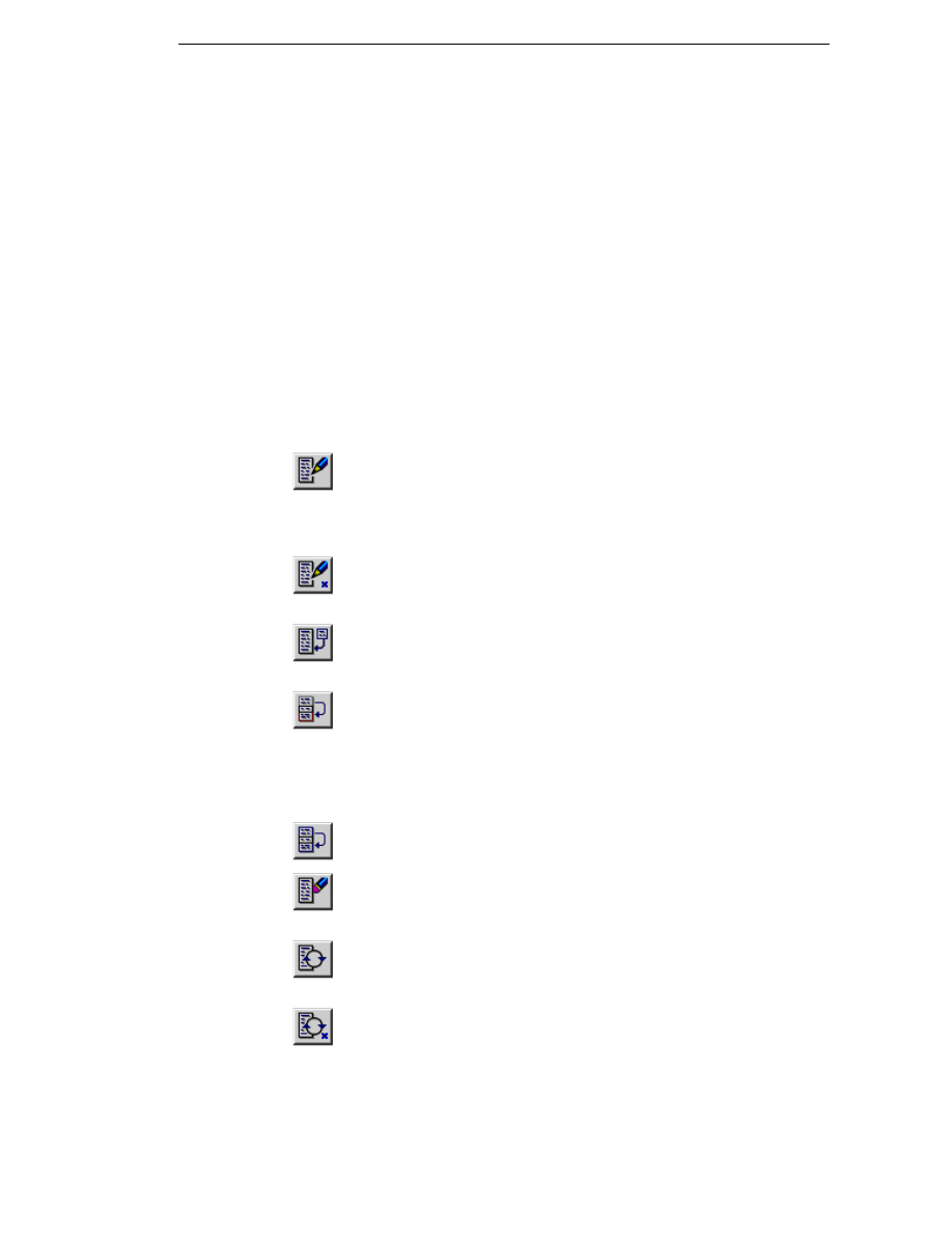
EdgeCAM Manufacture - User Guide
Using Instructions Menu Commands
Several commands in the Instructions menu allow you to alter existing
commands in the current instruction list.
Notes
Only commands that are included in the instruction list can be edited,
moved or deleted.
If you edit an Index (Move menu) command, all subsequent commands
may be invalidated.
Editing one or more sub-instructions within an Operation breaks the
Operation down into its constituent cycles.
Once the instruction list has been changed, EdgeCAM recalculates the
toolpath according to the new geometry.
The Instructions menu commands are:
Edit – Change a command’s parameters and any related co-ordinate
input. If you have deleted any entities, you must respecify the entities required
by the machining cycle. You can select more than one command at the same
time. Aborting or Escaping at this stage deletes the cycle.
Edit Screensnap – Change a command’s parameters and any related
co-ordinate input by digitising the appropriate toolpath.
Insert – On/off toggle. When on, it allows a new instruction(s) to be
inserted.
Move – Move a command’s position within the list. You may have to
create commands out of sequence, but Move allows you to correct the order
of events. You can select more than one command at the same time.
An example of this is when drilling a start hole for pocketing - you don’t know
where to drill the hole until after the Areaclear cycle has finished.
Copy – Duplicate a command at another location in the instruction list.
Delete – Remove a command from the instruction list. You can select
more than one command at the same time.
Regenerate – Regenerates the machining sequence from the selected
instruction onwards.
Regenerate Screensnap – Regenerates the machining sequence from
the digitised toolpath onwards.
Synchronise – (Only used for Four Axis Turning) Inserts a turret
synchronisation command into the instruction list.
75
Editing Instructions
View – Displays the machining sequence from the selected instruction
onwards, including parameter input and screen digitises.
View Screensnap – Displays the machining sequence from the
digitised toolpath onwards, including parameter input and screen digitises.
Simulate - Displays a tool simulation from the selected instruction onwards.
Simulate Screensnap – Displays a tool simulation from the digitised
toolpath onwards.
Operation – All subsequent instructions are grouped under an Operation
name, until you select the Operation command again.
Rationalise – (Milling environment only) Enables you to re-order the
instructions in a single sequence to rationalise the NC file by one or more
criteria. Choose between sorting by Tool, CPL or Index. Also see Re-ordering
the Machining Instructions in a Sequence.
Choosing the Editing Options
If you have selected a command using the Instructions menu, you can then
choose your editing options:
Screen Snap – Check this box to select the command by digitising the
appropriate toolpath, rather than by selecting the command from the
instruction list.
Operations – Check this box to list only those operations defined in the
current machining sequence, rather than all commands in the instruction list.
Operations can be defined with the Operation (Instructions menu) command.
Global – Check this box to alter the Feeds, Speeds and Depth... parameters
for all selected commands.
Redraw – Check this box to redraw the screen after you have edited the
instruction list.
Disable Automatic Regeneration – Check this box to only regenerate the
selected instructions. EdgeCAM defaults to regenerating all subsequent
instructions, which you might consider unnecessary and time-consuming if
you were simply changing the colour of the toolpath.
Caution – To avoid invalid results you should regenerate the toolpath
before saving or generating CNC code.
Click OK when you want to proceed.
76
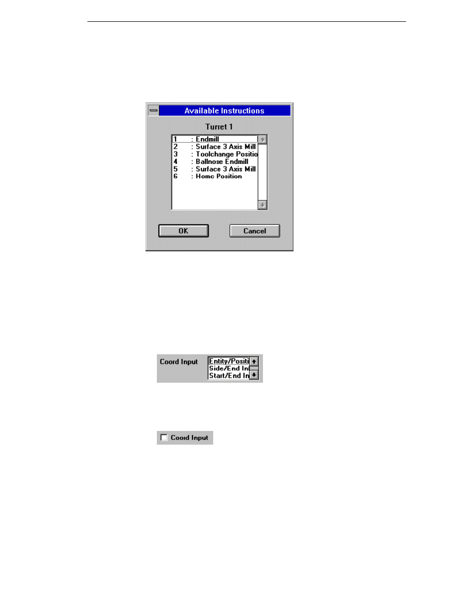
EdgeCAM Manufacture - User Guide
Selecting from the Instruction List
Unless you previously chose the Screen Snap option, you are now
presented with this box showing all the available commands in the current
instruction list that may be edited, moved or deleted.
1. Click on one or more commands from the list.
2. Click OK to continue.
Respecifying Co-ordinate Input
Once you have selected all the instructions that you want to edit, you are
presented with the dialog box for each command in turn.
If a command needs you to input co-ordinate information, a new
parameter is shown on the dialog - Coord Input.
Select one or more of the options. You can re-specify the co-ordinate
information for each of these aspects of the cycle after you click OK for
the cycle parameter input dialog box.
Coord Input may appear instead as follows:
Check this box to respecify the co-ordinates required by EdgeCAM. Once
you click on the OK button you are promted to enter this information in
the usual manner for the particular command.
77

Editing Instructions
78

Editing the Toolpath
EdgeCAM Manufacture - User Guide
D
ELETING A
S
ECTION OF A
T
OOLPATH
....................................................................80
E
DITING A
S
ECTION OF A
T
OOLPATH
.......................................................................80
S
PLITTING A
T
OOLPATH
.........................................................................................80
T
RANSFORMING THE
T
OOLPATHS
...........................................................................81
Notes on Translate Command ........................................................................83
Using Matrix Mode ..........................................................................................84
Please note that these options are only available in the milling and turning
environment
Several commands allow you to edit the toolpath itself. These can be selected
from Toolpath (Edit menu):
Section - Changes a toolpath section.
Split - Breaks up a toolpath.
Delete - Deletes a toolpath section.
Note that once a toolpath has been edited using one of these commands, it is no
longer a normal machining instruction and cannot be edited or regenerated.
Toolpaths that have been edited will be shown with an appropriate comment after
the command name in the instruction list.
79

Editing the Toolpath
Deleting a Section of a Toolpath
The command Toolpath Delete (Edit menu) lets you remove part of a toolpath
between two selected points. The system then creates a linear tool move to link
the two parts of the toolpath.
Link Control – (Milling only) Specifies how the link moves are to be created.
Select Shortest to create a single linear move. Select Retract to create a vertical
move to the Retract plane (defined below) before adding a link move.
Depth Parameters – (MIlling only) Specifies the Clearance and Retract depth
levels used by the system to generate the link moves.
Screen Snap – Check this box to select a toolpath from the screen rather than a
command from the instruction list.
Editing a Section of a Toolpath
The command Toolpath Section (Edit menu) lets you change part of a toolpath
between two selected points.
Location – Check this box to move a node on the toolpath. If you reposition an
arc move, it will change into a linear move.
Feedrate – Specify the tool feedrate in the workplane for the selected part of the
toolpath.
Plunge Feed – (Milling only) Specify the vertical tool feedrate (into and out of the
workplane) for the selected part of the toolpath.
Speed – Specify the spindle speed to be used during the selected part of the
toolpath.
Rapid – Check this box to change the selected part of the toolpath to all rapid
moves.
Screen Snap – Check this box to select the toolpath from the screen rather than
from the instruction list.
Splitting a Toolpath
The command Toolpath Split (Edit menu) lets you break a toolpath at a
selected point to produce two separate toolpaths. This lets you insert new
commands between the two toolpaths.
Screen Snap – Check this box to select a toolpath from the screen rather than a
command from the instruction list. The toolpath will then be broken at the point
nearest to the digitised point on the screen.
80
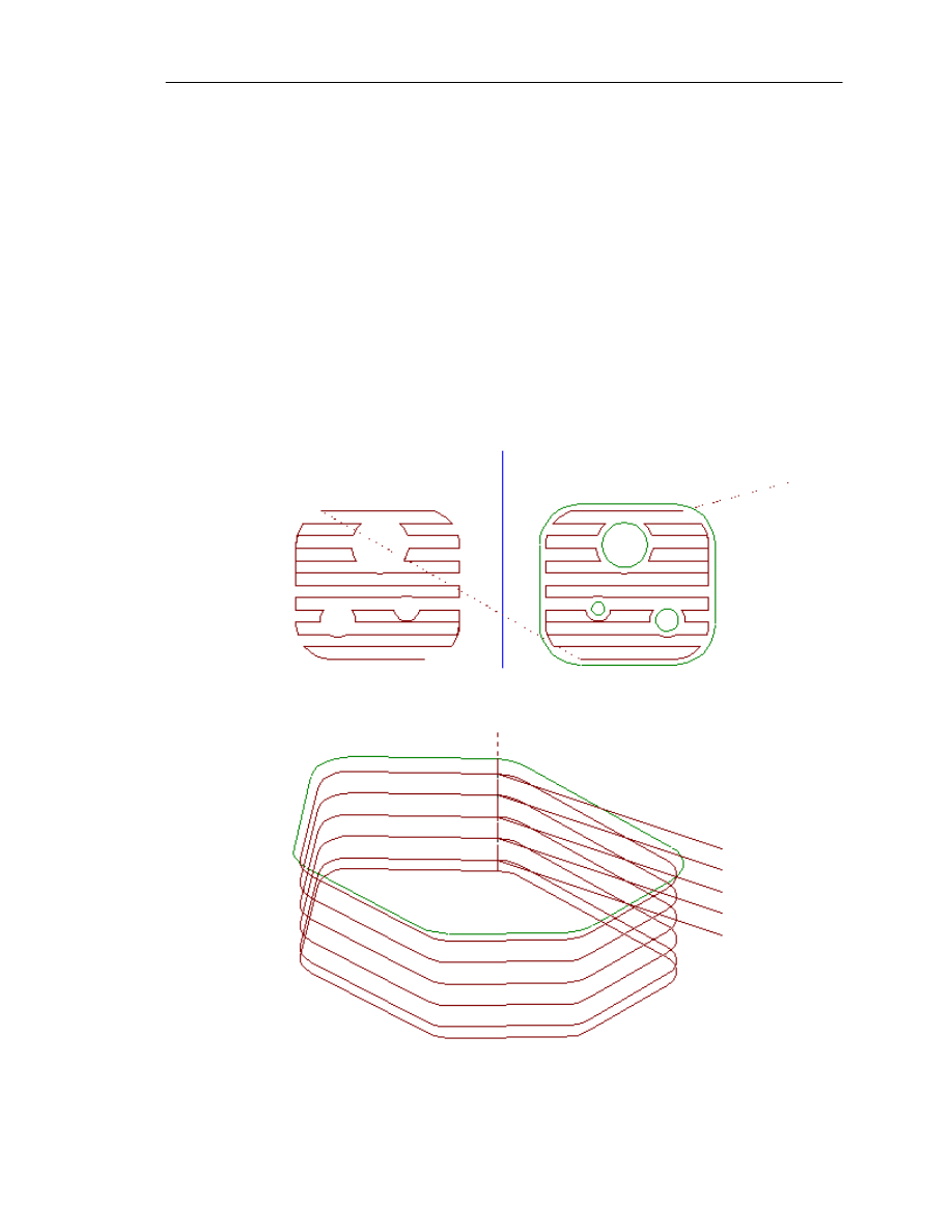
EdgeCAM Manufacture - User Guide
Transforming the Toolpaths
Several commands are available to copy or alter one or more machining
operations from the instruction list. Note that only the toolpaths are altered by
these commands – there is no alteration of the original design geometry. These
commands copy and transform the calculated toolpath. They do not regenerate
the path in its new position. This means that fixed points such as home or
toolchange positions and moves to Z clearance may not give the desired output.
Such moves should not be included in the instructions to be
transformed. Subroutines used for repeating the hole cycle positions may also be
invalidated as they will no longer have unique identifying numbers.
These are the Edit menu commands:
Transform Mirror – (Milling and Wire only) Mirrors a series of operations about a
selected plane:
Transform Repeat – (Milling only) Copies the toolpath at successive depths:
81
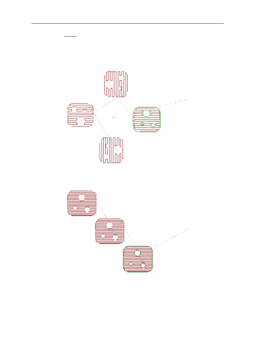
Editing the Toolpath
Do not set the Finish At parameter to Clearance or Retract for any cycles
transformed by this command. Otherwise Z moves will be output into the
subroutine which may invalidate the toolpath.
Transform Rotate – (Milling and Wire only) Rotates or copies a series of
operations one or more times about a selected point. This is used where the
same feature appears several times about a central point:
Transform Translate – Moves or copies a series of operations one or more
times. This is used where the same feature appears more than once in a
component. Also see Notes on Translate Command.
In Wire Erosion, you may only translate the toolpath in the X and Y directions.
82

EdgeCAM Manufacture - User Guide
Notes on Translate Command
Changes have been made in EdgeCAM 7.00 to the way in which the Translate
command works, particularly for controller subroutines. These changes result in a
better correlation between the moves shown by EdgeCAM graphics and the
toolpath on the machine tool.
Translated moves
EdgeCAM translates the toolpath as represented by move end points within the
designated labels. From a machine tool point of view the "Start" of a sub-routine is,
therefore, the End of the move leading to that first endpoint. Slightly different
results will be seen depending on the type of move. A direct rapid or feed move will
result in its end point being the subroutine start and the move will effectively be
"lost" in repeats of the subroutine. A 2D rapid, doglegged, move (e.g. XY and then
Z) will give the dogleg point as subroutine start and only the first segment of the
move will be lost.
Note that the graphics often show an apparent dogleg when resolved rapids are
not used. This intermediate point does not exist on the NC data - it is purely for
visualisation purposes - and will not be used as a start point.
Some previous changes in this area have been removed from EdgeCAM. This
means that in some cases the graphical representation will change, compared to
previous versions, to more closely represent what happens on the machine tool.
Good practice
For safety reasons, subroutines should always start and finish at a safe
clearance height. If this practice is followed then the link moves between
subroutines can be expected to also be at the safe height. The subroutine should
always include the liftout move at the end of a cut.
A specific move to a point near to the required start of the subroutine before
defining the subroutine is recommended. This is generally preferable to making a
move direct from, say, toolchange and relying on the 2D rapid's dogleg to be the
start point. If the machine tool movements are not exactly as represented on
screen then this will minimise the discrepancy.
Code Generators
Some additional system variables have been added to the Code Generator to
pass the subroutine start point.
In macros TRANSLATE and RESET, the variables XEND, YEND, ZEND now
represent the end of any approach move and thus the start of the subroutine.
In macros SUBSTART and SUBCALL, the existing variables NEXTXMOVE,
NEXTYMOVE, NEXTZMOVE can be used.
The TRANSLATE Macro (No. 32) should now use XEND etc. as subroutine
start point instead of XSUB etc. Rapid approach moves to this point should
be output.
The SUBSTART Macro (No. 55 ) should use NEXTXMOVE etc. as a "HOLD"
point for calculation of incremental moves.
The SUBCALL Macro (No. ) should include a rapid approach move to
NEXTXMOVE etc.
83

Editing the Toolpath
Existing code generator files will continue to work as before since no existing
variables have been changed. It may be, however, that their actions are not
correctly represented on screen by EdgeCAM graphics.
The Code Wizard templates for milling and turning have been updated to match
the graphics. Template based code generators should be updated to the version
7.00 templates to take advantage of these changes.
The templates have also been updated to make the switch between incremental
and absolute subroutines easier. The logic within the template will now determine
whether to use the Rapid or Translate code constructors and G90/91 blocks will
only be output by subroutine start and end if they are required. This last change
is within the default sequence of the code constructors. It will not be applied
automatically to updated CGD files but will be available for newly created files. It
should always be remembered that the exact action of a machine tool when
using controller cycles is beyond the control of EdgeCAM. It is the user's
reponsibility to ensure that his code generators are correctly configured and that
the on-screen representation closely matches the actions of his controllers.
Using Matrix Mode
Only available in the milling environment
Matrix Mode lets you repeat an operation or series of operations at regular
intervals, specifying the number of rows and columns you need in your grid or
matrix.
EdgeCAM always displays the selected geometry in the bottom left hand corner of
the Matrix. The various elements of the matrix are machined starting from the
bottom left hand corner by default. However, when you select a tool, the
Quadrant list box lets you start from the other corners of the Matrix. (Note that the
Quadrant parameter must have been enabled in your code generator for this to
work.)
Matrix Mode Start (Edit menu) is used before the sequence of machining
commands that are to be matrixed.
You now perform a normal sequence of toolchanges and machining cycles
on the geometry as a single part.
Matrix Mode Finish (Edit menu) is used after you have finished entering the
sequence of commands that are to be matrixed.
Each Matrix Mode Start must be completed with a Matrix Mode Finish
command.
Note that the Mode (View menu) command contains a ‘Matrix’ check box that
allows you to display or hide the Matrixed toolpath.
84
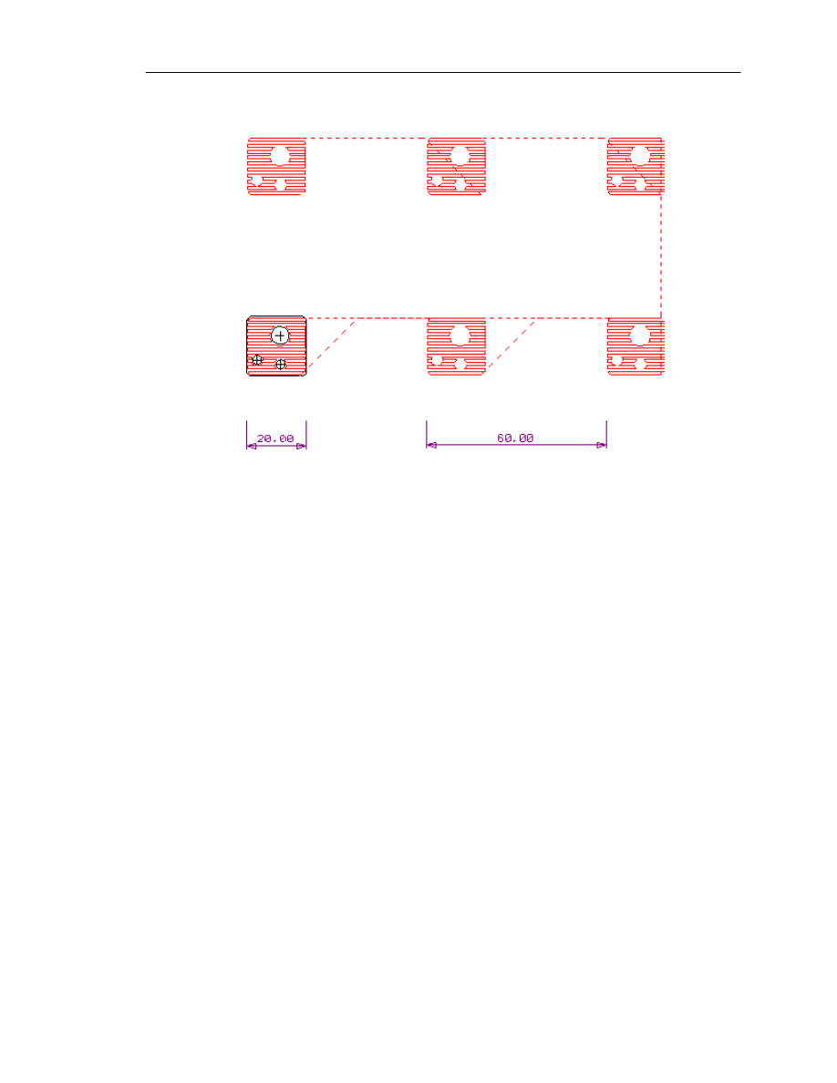
EdgeCAM Manufacture - User Guide
In the example below, a Lacing area clearance toolpath has been created after a
Matrix Mode Start:
On selecting the Matrix Mode Finish command, the Lacing toolpath is repeated
in a grid according to the parameters specified in the Matrix Mode Start
command.In this case, the parameters used were:
X Repeats = 3
X Length = 50
X Border = 5
Y Repeats = 2
Y Length = 50
Y Border = 5
The default double fret border spacing is used here, so the total spacing between
repeats of the toolpath is 50+5+5=60 as shown above.
Repeats – Specify the number of cells in the matrix in the X and Y direction.
Fret – Specify the number of Border widths (Double or Single) separating each
cell in the matrix.
Border – Specify the border spacing in part units in X and Y.
Length – Specify the distance between each cell in the matrix in X and Y.
Dead Zones – Allows you to specify areas that can be used by clamps or
fixturing. Define the dead zones by nominating two sides of the matrix rectangle
and a distance in from the edge.
85
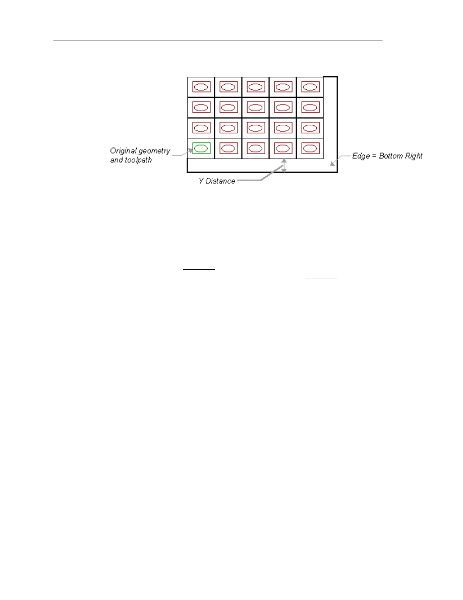
Editing the Toolpath
This example has X Repeats=5 and Y Repeats=4, and a Dead Zone along the
bottom right of the matrix:
Direction – Specifies which cell is to be machined after the first cell. Select
between Row or Column. Column forces the tool to move to a cell in the Y direction
and Row (the default) forces the tool to move to a cell in the X direction. Lace
Cut – Deselect to move the tool in the same direction along each row or column.
The default setting of the checked box moves the tool to the next cell with the
shortest possible movement.
Subroutines – Select Pathtrace to avoid using subroutines when generating
CNC code from this matrixed toolpath. The default setting of Controller will use
subroutines where available.
Define Layout – Select to ignore the Direction modifier and specify exactly in
which order the individual cells are to be machined. The system displays a
diagram of the cells in the matrix. Select each cell in the order you want the cells
machined in. As each cell is selected, it is given a number to show its position in
the sequence.
86
Generating CNC Code
EdgeCAM Manufacture - User Guide
P
ASSING
J
OB
D
ATA TO THE
NC F
ILE
................................................................89
A
BOUT
CNC F
ILENAMES
.................................................................................89
C
ODE
G
ENERATOR
C
OMMANDS
.......................................................................90
File Menu Commands in the Code Generator ..........................................90
View Menu Commands in the Code Generator ........................................91
Options Menu Commands in the Code Generator ....................................91
E
DITING THE
CNC C
ODE
.................................................................................92
Modifying a Code Generator File ..............................................................92
At some stage you will want to produce CNC code from your EdgeCAM
machining sequence information. To do this, you must use the Code
Generator application. This converts toolpath data generated within an
EdgeCAM machining sequence into files containing CNC code.
To generate the code from the active machining sequence
1. Select the Generate Code (File menu)
command.
2. Specify the following parameters:
CNC Name – Enter a name for the CNC file (the default file extension is
.nc). You can specify the file extension using the Default NC File
Extension option on the Toolpaths tab of the Preferences (Options
menu) dialog.
To save CNC file names in upper case check the Force Upper Case
option on the Toolpaths tab of the Preferences (Options menu) dialog.
Click on the Browse... button to select an existing file name to write over.
Job – Type in the name of the job file or press the Browse button to select
from a list of existing files. Also see Passing Job Data to the NC File.
Operation Names – Check the box to add operation names as
comments to the CNC file.
PDI Name – You can also name a category-run PDI file to execute
before NC code generation begins. This is provided for users who have
written their own PDIs and want to execute them before NC code
generation.
Open Editor – Check to automatically start the Editor and open the *.nc
file after code generation. Please note that this option is checked by
default.
3. Click on OK.
The Code Generator main window is now displayed.
87
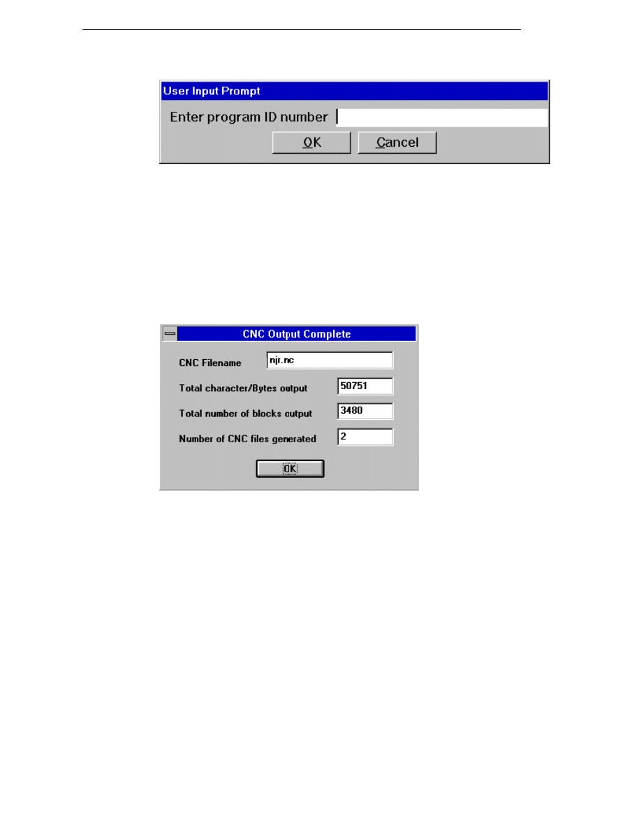
Generating CNC Code
If the Code Generator has been configured to ask for input before generating
the CNC code, then it displays a dialog box for each option for example.
You need to enter or accept the settings for each dialog box. Once you have
input this information, the Code Generator begins to generate code for the
active machining sequence.
If your system can compile Code Generator source files and you have
modified the source file, the system compiles a new Code Generator file
before compiling any CNC code.
The generation process can be paused, continued and stopped using the
controls.
When the code generation process finishes and if your Code Generator is set
up to list the NC code, EdgeCAM displays a dialog box.
Click on OK to dismiss this dialog box and return to EdgeCAM. If you did not
choose to list the NC code, you will be returned to EdgeCAM automatically
when the compilation ends.
88
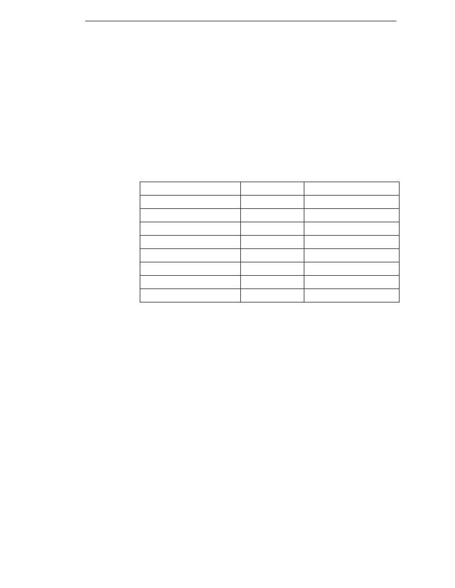
EdgeCAM Manufacture - User Guide
Passing Job Data to the NC File
When a job record is selected for a machining sequence the Comment,
Family, Customer, Programmer and Job Revision modifiers will be loaded
into EdgeCAM (if specified for the job record) and the values displayed in the
appropriate field on the Job Data tab.
This information along with Material, Machine and Description will be passed
through to the Code Generator, bringing the Job Manager, EdgeCAM
machining sequences and the NC file closer together.
You can also set these modifiers on the New Machining Sequence or
Machine Parameters dialog. The relevant fields in the Job Manager will be
updated when an NC file is generated.
Code Generator Variable
Token Name
Token Description
JOBDESC
JM-DESC
Job Manager Description
JOBCOM
JM-COM
Job Manager Comment
JOBFAM
JM-FAM
Job Manager Family
JOBMACH
JM-MACH
Job Manager Machine
JOBCUST
JM-CUST
Job Manager Customer
JOBPROG
JM-PROG
Job Manager Programmer
JOBMATL
JM-MATL
Job Manager Material
JOBREV
JM-REV
Job Manager Revision
About CNC Filenames
When a milling or single turret turning sequence is generated, the CNC
filename is generated to the following format:
CNC file
- example.nc
Setup file (optional)
- example-set.nc
When a single .nc file is generated, there is no ‘-1’ included in the name. This
clarifies that the file is for a single turret machine. You can specify an extension
other than ‘.nc’.
When a multiple turret turning sequence is generated, the CNC filename is
generated to the following format:
1st CNC file
- example-1.nc
2nd CNC file
- example-2.nc
Setup file (optional)
- example-set.nc
89

Generating CNC Code
The EdgeCAM Editor and Communications modules interpret and use long
filenames generated from EdgeCAM (or any application) when running on a
Windows NT installation.
Note, however, that long filenames are truncated when viewed from Windows
3.1 and Novell networks. For example, the file 1234567890abc.nc will be
truncated to 123456~.nc.
The name assigned to the ‘setup’ file is configurable in the Code Generator
source file, for example, instead of including -SETUP in the filename, it may
be specified as -HEADER.
Any CNC file generated using an existing Code Generator that specifies a
‘setup’ file name should be ignored and .set appended to the filename in its
place.
Code Generator Commands
File Menu Commands in the Code Generator
Select Code Generator - Selects the Code Generator source file to be
compiled.
Print - Sends the current file to the printer.
Print Preview - Shows how the current file would appear if sent to the
printer.
Print Setup - Configures the printer setup.
Compile - Displays a dialog box containing the file compilation options. An
input file is selected and the filenames for all other options are automatically
entered. These filenames default to the same name as the input filename
followed by the appropriate extension. The name can be re-specified by the
user if required.
This option is applicable to the Code Generator Compiler only, and will be
“greyed out” if you do not have a licence.
Exit - Returns to the previous application.
90
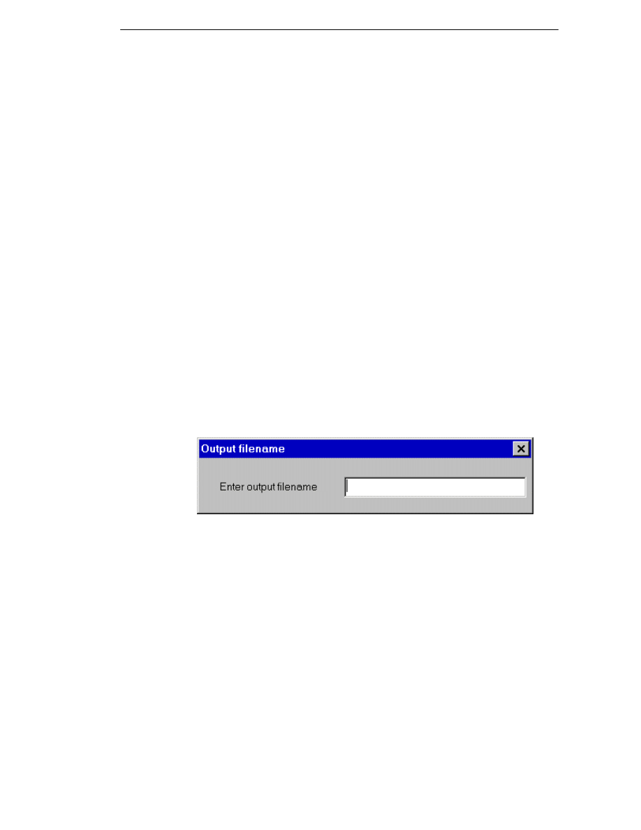
EdgeCAM Manufacture - User Guide
View Menu Commands in the Code Generator
Toolbar - Shows/hides the Toolbar.
Status Bar - Shows/hides the Status bar.
Large Icons - Uses the larger of the two icon sets for the Code Generator's
buttons.
Tool Tips - Allows command names to be displayed if you hold the cursor
over a button.
Options Menu Commands in the Code Generator
Re-run - Regenerates the CNC code using the data files for the last code
generation. This forces a re-compilation of the Code Generator file if the date
and time of the source is later that that of the Code Generator.
Pause - Pauses\continues the active process. This lets you inspect the
information displayed in the text box. Use the horizontal and vertical scroll
bars to move up and down the file.
Stop - Aborts the process.
Remove Unused Variables - Instructs the compiler to remove any duplicate
or unused variables from the source file (*.?xt)
Quick Compile - Forces a quicker compilation by displaying the minimum
amount of feedback in the viewing window.
Specify Output Filename - Selecting this Code Generator Compiler-only
option displays a dialog box similar to this after you click on the Compile
button:
Enter a different name for the compiled Code Generator file. If this option is
not selected, the source filename will be used by default.
91
Generating CNC Code
Editing the CNC Code
Once the Code Generator has created a file containing CNC code for a
machining sequence, you can load the file into the Editor and make any
changes directly to the code, should they be required.
To enter the Editor, select the
icon from the EdgeCAM Program Group.
For more details, please refer to the Editor documentation.
Modifying a Code Generator File
One way to alter the CNC code produced for a machining sequence is to edit
the Code Generator itself. The recommended method for modifying Code
Generators is to load the files into the Code Wizard
.
You must know how Code Generator source files work before trying
this!
For more details, please refer to the Code Wizard online user guide.
92
Wyszukiwarka
Podobne podstrony:
Edgecam Manufacturing Basics
Lean Manufacturing Basics Aza Badurdeen [ENG]
Manufacturing basics id 279151 Nieznany
Lean Manufacturingnd The Enviroment (2003)
edgecam
Generating CNC Code with Edgeca Nieznany
2009 11 17 arduino basics
LV Basics I (2)
Excel VBA Course Notes 1 Macro Basics
CATIA V5 Training Basics
Films, Manufacture
EdgeCAM 10 0 Instalacja
EdgeCAM 2013 instalacja i konfiguracja
AT2H Basics Hindu Culture Part 2
AT2H Basics Education in Ancient India
Lean manufacturing, Zarządzanie produkcją i usługami
więcej podobnych podstron