
EUROPEAN STANDARD
EN 1994-1-1:2004
NORME EUROPÉENNE
EUROPÄISCHE NORM
1 September 2004
UDC
Descriptores:
English version
Eurocode 4: Design of composite steel and concrete structures
Part 1-1: General rules and rules for buildings
Structures mixtes acier-beton,
calcul et construction
Partie 1-1 :
Règles générales et
règles pour les bâtiments
Bemessung und Konstruktion von
Verbundtragwerken aus Stahl und Beton
Teil 1-1:
Allgemeine Bemessungsregeln und
Anwendungsregeln für den Hochbau
Stage 49
Final Version of the Editorial Group
CEN
European Committee for Standardization
Comité Européen de Normalisation
Europäisches Komitee für Normung
Central Secretariat: rue de Stassart 36, B-1050 Brussels
© CEN 2004 Copyright reserved to all CEN members
Ref. No. EN 1994-1-1:2004 E

EN 1994-1-1: 2004 (E)
2
Contents
Page
Foreword……………………………………………………………………………………… 8
Section 1 General……………………………………………………………………………. 12
1.1 Scope……………………………………………………………………………………… 12
1.1.1 Scope of Eurocode 4………………………………………………………………… 12
1.1.2 Scope of Part 1.1 of Eurocode 4…………………………………………………….. 12
1.2 Normative references…………………………………………………………………….. 13
1.2.1 General reference standards…………………………………………………………. 13
1.2.2 Other reference standards……………………………………………………………. 13
1.3 Assumptions………………………………………………………………………………. 14
1.4 Distinction between principles and application rules…………………………………….. 14
1.5 Definitions……………………………………………………………………………….. 14
1.5.1 General……………………………………………………………………………… 14
1.5.2 Additional terms and definitions used in this Standard……………………………. 14
1.6 Symbols…………………………………………………………………………………. 15
Section 2 Basis of design……………………………………………………………………. 22
2.1 Requirements…………………………………………………………………………….. 22
2.2 Principles of limit state design…………………………………………………………… 23
2.3 Basic variables……………………………………………………………………………. 23
2.3.1 Actions and environmental influences………………………………………………. 23
2.3.2 Material and product properties……………………………………………………… 23
2.3.3 Classification of actions……………………………………………………………… 23
2.4 Verification by the partial factor method…………………………………………………. 23
2.4.1 Design values……………………………………………………………………….. 23
2.4.1.1 Design values of actions……………………………………………………… 23
2.4.1.2 Design values of material or product properties……………………………… 23
2.4.1.3 Design values of geometrical data……………………………………………. 24
2.4.1.4 Design resistances ……………………………………………………………. 24
2.4.2 Combination of actions……………………………………………………………… 24
2.4.3 Verification of static equilibrium (EQU)…………………………………………… 24
Section 3 Materials…………………………………………………………………………. 24
3.1 Concrete…………………………………………………………………………………. 24
3.2 Reinforcing steel………………………………………………………………………… 25
3.3 Structural steel…………………………………………………………………………… 25
3.4 Connecting devices………………………………………………………………………. 25
3.4.1 General………………………………………………………………………………. 25
3.4.2 Headed stud shear connectors………………………………………………………. 25
3.5 Profiled steel sheeting for composite slabs in buildings…………………………………. 25
Section 4 Durability………………………………………………………………………………. 25
4.1 General……………………………………………………………………………………. 25
4.2 Profiled steel sheeting for composite slabs in buildings………………………………….. 26

EN 1994-1-1:2004 (E)
3
Section 5 Structural analysis………………………………………………………………... 26
5.1 Structural modelling for analysis………………………………………………………….. 26
5.1.1 Structural modelling and basic assumptions………………………………………….. 26
5.1.2 Joint modelling………………………………………………………………………… 26
5.1.3 Ground-structure interaction………………………………………………………….. 26
5.2 Structural stability…………………………………………………………………………. 27
5.2.1 Effects of deformed geometry of the structure……………………………………….. 27
5.2.2 Methods of analysis for buildings…………………………………………………….. 27
5.3 Imperfections………………………………………………………………………………. 28
5.3.1 Basis…………………………………………………………………… ……………… 28
5.3.2 Imperfections in buildings…………………………………………………………… 28
5.3.2.1
General………………………………………………………………………….
28
5.3.2.2 Global imperfections…………………………………………………………… 29
5.3.2.3 Member imperfections…………………………………………………………. 29
5.4 Calculation of action effects………………………………………………………………… 29
5.4.1 Methods of global analysis…………………………………………………………….. 29
5.4.1.1
General…………………………………………………………………………..
29
5.4.1.2 Effective width of flanges for shear lag………………………………………… 29
5.4.2 Linear elastic analysis………………………………………………………………….. 31
5.4.2.1
General………………………………………………………………………….
31
5.4.2.2 Creep and shrinkage…………………………………………………………… 31
5.4.2.3 Effects of cracking of concrete…………………………………………………. 32
5.4.2.4 Stages and sequence of construction…………………………………………… 33
5.4.2.5 Temperature effects…………………………………………………………….. 33
5.4.2.6 Pre-stressing by controlled imposed deformations……………………………… 33
5.4.3 Non-linear global analysis……………………………………………………………. 33
5.4.4 Linear elastic analysis with limited redistribution for buildings………………………. 33
5.4.5 Rigid plastic global analysis for buildings…………………………………………….. 35
5.5 Classification of cross-sections…………………………………………………………….. 36
5.5.1 General………………………………………………………………………………… 36
5.5.2 Classification of composite sections without concrete encasement…………………… 37
5.5.3 Classification of composite sections for buildings with concrete
encasement……………………………………………………………………………. 37
Section 6 Ultimate limit states……………………………………………………………………… 38
6.1 Beams………………………………………………………………………………………. 38
6.1.1 Beams for buildings……………………………………………………………………. 38
6.1.2 Effective width for verification of cross-sections……………………………………… 39
6.2 Resistances of cross-sections of beams………………………………………………………39
6.2.1 Bending resistance……………………………………………………………………. 39
6.2.1.1
General…………………………………………………………………………
39
6.2.1.2 Plastic resistance moment M
pl,Rd
of a composite cross-section………………. 40
6.2.1.3 Plastic resistance moment of sections with partial shear
connection in buildings………………………………………………………
41
6.2.1.4 Non-linear resistance to bending…………………………………………….
42
6.2.1.5 Elastic resistance to bending…………………………………………………
44
6.2.2 Resistance to vertical shear………………………………………………………….
44
6.2.2.1
Scope………………………………………………………………………….
44
6.2.2.2 Plastic resistance to vertical shear……………………………………………. 44

EN 1994-1-1: 2004 (E)
4
6.2.2.3 Shear buckling resistance………………………………………………………… 44
6.2.2.4 Bending and vertical shear………………………………………………………. 45
6.3 Resistance of cross-sections of beams for buildings with partial
encasement……………………………………………………………………………………. 45
6.3.1 Scope……………………………………………………………………………………… 45
6.3.2 Bending resistance…………………………………………………………………………46
6.3.3 Resistance to vertical shear……………………………………………………………….. 46
6.3.4 Bending and vertical shear…………………………………………………………………47
6.4 Lateral-torsional buckling of composite beams……………………………………………….. 47
6.4.1 General……………………………………………………………………………………. 47
6.4.2 Verification of lateral-torsional buckling of continuous composite
beams with cross-sections in Class 1, 2 and 3 for buildings………………………………48
6.4.3 Simplified verification for buildings without direct calculation………………………… 50
6.5 Transverse forces on webs…………………………………………………………………… 51
6.5.1 General…………………………………………………………………………………… 51
6.5.2 Flange-induced buckling of webs………………………………………………………… 51
6.6 Shear connection……………………………………………………………………………… 51
6.6.1 General…………………………………………………………………………………… 51
6.6.1.1 Basis of design…………………………………………………………………….. 51
6.6.1.2 Limitation on the use of partial shear connection in beams
for buildings……………………………………………………………………….. 52
6.6.1.3 Spacing of shear connectors in beams for buildings……………………………… 53
6.6.2 Longitudinal shear force in beams for buildings…………………………………………..54
6.6.2.1 Beams in which non-linear or elastic theory is used for
resistances of one or more cross-sections…………………………………………..54
6.6.2.2 Beams in which plastic theory is used for resistance of
cross-sections……………………………………………………………………… 54
6.6.3 Headed stud connectors in solid slabs and concrete encasement………………………….54
6.6.3.1 Design resistance………………………………………………………………… 54
6.6.3.2 Influence of tension on shear resistance………………………………………….. 55
6.6.4 Design resistance of headed studs used with profiled steel sheeting
in buildings……………………………………………………………………………… 55
6.6.4.1 Sheeting with ribs parallel to the supporting beams………………………………. 55
6.6.4.2 Sheeting with ribs transverse to the supporting beams……………………………. 56
6.6.4.3 Biaxial loading of shear connectors……………………………………………….. 57
6.6.5 Detailing of the shear connection and influence of execution…………………………… 57
6.6.5.1 Resistance to separation………………………………………………………….. 57
6.6.5.2 Cover and concreting for buildings………………………………………………. 57
6.6.5.3 Local reinforcement in the slab…………………………………………………… 57
6.6.5.4 Haunches other than formed by profiled steel sheeting……………………….… 58
6.6.5.5 Spacing of connectors……………………………………………………………. 58
6.6.5.6 Dimensions of the steel flange……………………………………………………. 59
6.6.5.7 Headed stud connectors………………………………………………………….. 59
6.6.5.8 Headed studs used with profiled steel sheeting in buildings……………………. 59
6.6.6 Longitudinal shear in concrete slabs…………………………………………………….. 59
6.6.6.1
General…………………………………………………………………………….
59
6.6.6.2 Design resistance to longitudinal shear…………………………………………… 60
6.6.6.3 Minimum transverse reinforcement………………………………………………. 61
6.6.6.4 Longitudinal shear and transverse reinforcement in beams
for buildings………………………………………………………………………. 61

EN 1994-1-1:2004 (E)
5
6.7 Composite columns and composite compression members……………………………….. 62
6.7.1 General……………………………………………………………………………….. 62
6.7.2 General method of design ……………………………………………………………. 64
6.7.3 Simplified method of design…………………………………………………………. 64
6.7.3.1 General and scope……………………………………………………………… 64
6.7.3.2 Resistance of cross-sections…………………………………………………….. 65
6.7.3.3 Effective flexural stiffness, steel contribution ratio and
relative slenderness……………………………………………………………… 67
6.7.3.4 Methods of analysis and member imperfections……………………………….. 68
6.7.3.5 Resistance of members in axial compression…………………………………… 69
6.7.3.6 Resistance of members in combined compression and
uniaxial bending…………………………………………………………………. 71
6.7.3.7 Combined compression and biaxial bending……………………………………. 71
6.7.4 Shear connection and load introduction……………………………………………… 72
6.7.4.1
General…………………………………………………………………………
72
6.7.4.2 Load introduction……………………………………………………………….. 73
6.7.4.3 Longitudinal shear outside the areas of load introduction………………………. 75
6.7.5 Detailing Provisions…………………………………………………………………….. 76
6.7.5.1 Concrete cover of steel profiles and reinforcement………………………………76
6.7.5.2 Longitudinal and transverse reinforcement………………………………………76
6.8 Fatigue………………………………………………………………………………………..77
6.8.1 General…………………………………………………………………………………. 77
6.8.2 Partial factors for fatigue assessment for buildings…………………………………….. 77
6.8.3 Fatigue strength…………………………………………………………………………. 77
6.8.4 Internal forces and fatigue loadings…………………………………………………….. 78
6.8.5 Stresses …………………………………………………………………………………. 78
6.8.5.1
General…………………………………………………………………………
78
6.8.5.2
Concrete…………………………………………………………………………
79
6.8.5.3 Structural steel………………………………………………………………….. 79
6.8.5.4
Reinforcement…………………………………………………………………..
79
6.8.5.5 Shear connection……………………………………………………………… 80
6.8.6 Stress ranges……………………………………………………………………………. 80
6.8.6.1 Structural steel and reinforcement……………………………………………… 80
6.8.6.2 Shear connection……………………………………………………………… 80
6.8.7 Fatigue assessment based on nominal stress ranges…………………………………… 81
6.8.7.1 Structural steel, reinforcement, and concrete………………………………… 81
6.8.7.2 Shear connection……………………………………………………………… 82
Section 7 Serviceability limit states…………………………………………………………… 82
7.1 General……………………………………………………………………………………… 82
7.2 Stresses……………………………………………………………………………………… 82
7.2.1 General…………………………………………………………………………………. 82
7.2.2 Stress limitation for buildings…………………………………………………………. 83
7.3 Deformations in buildings………………………………………………………………….. 83
7.3.1 Deflections……………………………………………………………………………… 83
7.3.2 Vibration……………………………………………………………………………….. 84
7.4 Cracking of concrete………………………………………………………………………… 84
7.4.1 General………………………………………………………………………………… 84
7.4.2 Minimum reinforcement……………………………………………………………….. 85
7.4.3 Control of cracking due to direct loading……………………………………………… 86

EN 1994-1-1: 2004 (E)
6
Section 8 Composite joints in frames for buildings………………………………………… 88
8.1 Scope……………………………………………………………………………………….. 88
8.2 Analysis, modelling and classification……………………………………………………… 88
8.2.1 General………………………………………………………………………………… 88
8.2.2 Elastic global analysis…………………………………………………………………. 88
8.2.3 Classification of joints…………………………………………………………………. 88
8.3 Design methods……………………………………………………………………………… 89
8.3.1 Basis and scope…………………………………………………………………………. 89
8.3.2 Resistance……………………………………………………………………………… 89
8.3.3 Rotational stiffness…………………………………………………………………….. 89
8.3.4 Rotation capacity………………………………………………………………………. 89
8.4 Resistance of components………………………………………………………………….. 89
8.4.1 Scope…………………………………………………………………………………… 89
8.4.2 Basic joint components………………………………………………………………… 90
8.4.2.1 Longitudinal steel reinforcement in tension……………………………………. 90
8.4.2.2 Steel contact plate in compression……………………………………………… 90
8.4.3 Column web in transverse compression…………………………………………………91
8.4.4 Reinforced components………………………………………………………………… 91
8.4.4.1 Column web panel in shear…………………………………………………….. 91
8.4.4.2 Column web in compression …………………………………………………… 91
Section 9 Composite slabs with profiled steel sheeting for buildings………………………. 92
9.1 General……………………………………………………………………………………… 92
9.1.1 Scope…………………………………………………………………………………… 92
9.1.2 Definitions……………………………………………………………………………… 93
9.1.2.1 Types of shear connection……………………………………………………… 93
9.1.2.2 Full shear connection am partial shear connection……………………………… 93
9.2 Detailing provisions…………………………………………………………………………. 93
9.2.1 Slab thickness and reinforcement………………………………………………………. 93
9.2.2 Aggregate………………………………………………………………………………. 94
9.2.3 Bearing requirements…………………………………………………………………… 94
9.3 Actions and action effects…………………………………………………………………… 95
9.3.1 Design situations……………………………………………………………………….. 95
9.3.2 Actions for profiled steel sheeting as shuttering………………………………………. 95
9.3.3 Actions for composite slab……………………………………………………………. 95
9.4 Analysis for internal forces and moments………………………………………………….. 95
9.4.1 Profiled steel sheeting as shuttering…………………………………………………… 95
9.4.2 Analysis of composite slab……………………………………………………………. 96
9.4.3 Effective width of composite slab for concentrated point and
line loads……………………………………………………………………………… 96
9.5 Verification of profiled steel sheeting as shuttering for ultimate
limit states………………………………………………………………………………….. 97
9.6 Verification of profiled steel sheeting as shuttering for
serviceability limit states…………………………………………………………………… 97
9.7 Verification of composite slabs for ultimate limit states…………………………………… 98
9.7.1 Design criterion……………………………………………………………………….. 98
9.7.2 Flexure………………………………………………………………………………… 98
9.7.3 Longitudinal shear for slabs without end anchorage…………………………………… 99
9.7.4 Longitudinal shear for slabs with end anchorage……………………………………… 101

EN 1994-1-1:2004 (E)
7
9.7.5 Vertical shear…………………………………………………………………….. 101
9.7.6 Punching shear…………………………………………………………………… 101
9.8 Verification of composite slabs for serviceability limit states………………………… 102
9.8.1 Control of cracking of concrete…………………………………………………… 102
9.8.2 Deflection………………………………………………………………………… 102
Annex A (Informative) Stiffness of joint components in buildings…………………… 104
A.1 Scope………………………………………………………………………………….. 104
A.2 Stiffness coefficients…………………………………………………………………… 104
A.2.1 Basic joint components…………………………………………………………… 104
A.2.1.1 Longitudinal steel reinforcement in tension………………………………. 104
A.2.1.2 Steel contact plate in compression………………………………………… 104
A.2.2 Other components in composite joints…………………………………………… 104
A.2.2.1 Column web panel in shear………………………………………………. 104
A.2.2.2 Column web in transverse compression………………………………………….. 104
A.2.3 Reinforced components…………………………………………………………….. 106
A.2.3.1 Column web panel in shear……………………………………………… 106
A.2.3.2 Column web in transverse compression…………………………………. 106
A.3 Deformation of the shear connection………………………………………………… 106
Annex B (Informative) Standard tests……………………………………………………….. 108
B.1 General……………………………………………………………………………….. 108
B.2 Tests on shear connectors……………………………………………………………. 108
B.2.1 General………………………………………………………………………….. 108
B.2.2 Testing arrangements…………………………………………………………… 108
B.2.3 Preparation of specimens………………………………………………………… 109
B.2.4 Testing procedure……………………………………………………………….. 110
B.2.5 Test evaluation……………………………………………………………………. 110
B.3 Testing of composite floor slabs………………………………………………………. 111
B.3.1 General…………………………………………………………………………… 111
B.3.2 Testing arrangement………………………………………………………………. 111
B.3.3 Preparation of specimens…………………………………………………………. 112
B.3.4 Test loading procedure……………………………………………………………. 113
B.3.5 Determination of design values for m and k……………………………………… 114
B.3.6 Determination of the design values for
τ
u,Rd
……………………………………… 114
Annex C (Informative) Shrinkage of concrete for composite structures
for buildings…………………………………………………………………………………… 116
Bibliography…………………………………………………………………………….. 117

EN 1994-1-1: 2004 (E)
8
Foreword
This document (EN 1994-1-1:2004), Eurocode 4: Design of composite steel and concrete structures:
Part 1-1 General rules and rules for buildings, has been prepared on behalf of Technical Committee
CEN/TC 250 "Structural Eurocodes", the Secretariat of which is held by BSI.
This European Standard shall be given the status of a national standard, either by publication of an
identical text or by endorsement, at the latest by MM/YY, and conflicting national standards shall
be withdrawn at the latest by March 2010.
This document supersedes ENV 1994-1-1:1992.
CEN/TC 250 is responsible for all Structural Eurocodes.
According to the CEN/CENELEC Internal Regulations, the national standards organizations of the
following countries are bound to implement this European Standard: Austria, Belgium, Cyprus,
Czech Republic, Denmark, Estonia, Finland, France, Germany, Greece, Hungary, Iceland, Ireland,
Italy, Latvia, Lithuania, Luxembourg, Malta, the
Netherlands, Norway, Poland, Portugal, Slovakia,
Slovenia, Spain, Sweden, Switzerland and the United Kingdom.
Background of the Eurocode programme
In 1975, the Commission of the European Community decided on an action programme in the field
of construction, based on article 95 of the Treaty. The objective of the programme was the
elimination of technical obstacles to trade and the harmonisation of technical specifications.
Within this action programme, the Commission took the initiative to establish a set of harmonised
technical rules for the design of construction works which, in a first stage, would serve as an
alternative to the national rules in force in the Member States and, ultimately, would replace them.
For fifteen years, the Commission, with the help of a Steering Committee with Representatives of
Member States, conducted the development of the Eurocodes programme, which led to the first
generation of European codes in the 1980s.
In 1989, the Commission and the Member States of the EU and EFTA decided, on the basis of an
agreement
1
between the Commission and CEN, to transfer the preparation and the publication of the
Eurocodes to CEN through a series of Mandates, in order to provide them with a future status of
European Standard (EN). This links de facto the Eurocodes with the provisions of all the Council’s
Directives and/or Commission’s Decisions dealing with European standards (e.g. the Council
Directive 89/106/EEC on construction products - CPD - and Council Directives 93/37/EEC,
92/50/EEC and 89/440/EEC on public works and services and equivalent EFTA Directives initiated
in pursuit of setting up the internal market).
The Structural Eurocode programme comprises the following standards generally consisting of a
number of Parts:
EN 1990
Eurocode :
Basis of Structural Design
EN 1991
Eurocode 1:
Actions on structures
EN 1992
Eurocode 2:
Design of concrete structures
EN 1993
Eurocode 3:
Design of steel structures
1
Agreement between the Commission of the European Communities and the European Committee for Standardisation (CEN) concerning the work on
EUROCODES for the design of building and civil engineering works (BC/CEN/03/89).

EN 1994-1-1:2004 (E)
9
EN 1994
Eurocode 4:
Design of composite steel and concrete structures
EN 1995
Eurocode 5:
Design of timber structures
EN 1996
Eurocode 6:
Design of masonry structures
EN 1997
Eurocode 7:
Geotechnical design
EN 1998
Eurocode 8:
Design of structures for earthquake resistance
EN 1999
Eurocode 9:
Design of aluminium structures
Eurocode standards recognise the responsibility of regulatory authorities in each Member State and
have safeguarded their right to determine values related to regulatory safety matters at national level
where these continue to vary from State to State.
Status and field of application of Eurocodes
The Member States of the EU and EFTA recognise that Eurocodes serve as reference documents for
the following purposes:
– as a means to prove compliance of building and civil engineering works with the essential
requirements of Council Directive 89/106/EEC, particularly Essential Requirement N°1 –
Mechanical resistance and stability – and Essential Requirement N°2 – Safety in case of fire ;
–
as a basis for specifying contracts for construction works and related engineering services ;
–
as a framework for drawing up harmonised technical specifications for construction products
(ENs and ETAs)
The Eurocodes, as far as they concern the construction works themselves, have a direct relationship
with the Interpretative Documents
2
referred to in Article 12 of the CPD, although they are of a
different nature from harmonised product standards
3
. Therefore, technical aspects arising from the
Eurocodes work need to be adequately considered by CEN Technical Committees and/or EOTA
Working Groups working on product standards with a view to achieving full compatibility of these
technical specifications with the Eurocodes.
The Eurocode standards provide common structural design rules for everyday use for the design of
whole structures and component products of both a traditional and an innovative nature. Unusual
forms of construction or design conditions are not specifically covered and additional expert
consideration will be required by the designer in such cases.
National Standards implementing Eurocodes
The National Standards implementing Eurocodes will comprise the full text of the Eurocode
(including any annexes), as published by CEN, which may be preceded by a National title page and
National foreword, and may be followed by a National annex.
2
According to Art. 3.3 of the CPD, the essential requirements (ERs) shall be given concrete form in interpretative documents for the creation of the
necessary links between the essential requirements and the mandates for harmonised ENs and ETAGs/ETAs.
3
According to Art. 12 of the CPD the interpretative documents shall :
a)
give concrete form to the essential requirements by harmonising the terminology and the technical bases and indicating classes
or levels for each requirement where necessary ;
b)
indicate methods of correlating these classes or levels of requirement with the technical specifications, e.g. methods of
calculation and of proof, technical rules for project design, etc. ;
c)
serve as a reference for the establishment of harmonised standards and guidelines for European technical approvals.
The Eurocodes, de facto, play a similar role in the field of the ER 1 and a part of ER 2.

EN 1994-1-1: 2004 (E)
10
The National annex may only contain information on those parameters which are left open in the
Eurocode for national choice, known as Nationally Determined Parameters, to be used for the
design of buildings and civil engineering works to be constructed in the country concerned, i.e.:
- values and/or classes where alternatives are given in the Eurocode,
- values to be used where a symbol only is given in the Eurocode,
- country specific data (geographical, climatic, etc.), e.g. snow map,
- the procedure to be used where alternative procedures are given in the Eurocode.
It may also contain
-
decisions on the use of informative annexes, and
- references to non-contradictory complementary information to assist the user to apply the
Eurocode.
Links between Eurocodes and harmonised technical specifications (ENs and ETAs)
for products
There is a need for consistency between the harmonised technical specifications for construction
products and the technical rules for works
4.
Furthermore, all the information accompanying the CE
Marking of the construction products which refer to Eurocodes shall clearly mention which
Nationally Determined Parameters have been taken into account.
Additional information specific to EN 1994-1-1
EN 1994-1-1 describes the Principles and requirements for safety, serviceability and durability of
composite steel and concrete structures, together with specific provisions for buildings. It is based
on the limit state concept used in conjunction with a partial factor method.
For the design of new structures, EN 1994-1-1 is intended to be used, for direct application,
together with other Parts of EN 1994, Eurocodes EN 1990 to 1993 and Eurocodes EN 1997 and
1998.
EN 1994-1-1 also serves as a reference document for other CEN TCs concerning structural matters.
EN 1994-1-1 is intended for use by:
–
committees drafting other standards for structural design and related product, testing and
execution standards ;
–
clients (e.g. for the formulation of their specific requirements on reliability levels and durability)
;
–
designers and constructors ;
–
relevant authorities.
Numerical values for partial factors and other reliability parameters are recommended as basic
values that provide an acceptable level of reliability. They have been selected assuming that an
appropriate level of workmanship and of quality management applies. When EN 1994-1-1 is used
as a base document by other CEN/TCs the same values need to be taken.
4
see Art.3.3 and Art.12 of the CPD, as well as clauses 4.2, 4.3.1, 4.3.2 and 5.2 of ID 1.

EN 1994-1-1:2004 (E)
11
National annex for EN 1994-1-1
This standard gives values with notes indicating where national choices may have to be made.
Therefore the National Standard implementing EN 1994-1-1 should have a National annex
containing all Nationally Determined Parameters to be used for the design of buildings and civil
engineering works to be constructed in the relevant country.
National choice is allowed in EN 1994-1-1 through the following clauses:
- 2.4.1.1(1)
- 2.4.1.2(5)
- 2.4.1.2(6)
- 2.4.1.2(7)
- 3.1(4)
- 3.5(2)
- 6.4.3(1)(h)
- 6.6.3.1(1)
- 6.6.3.1(3)
- 6.6.4.1(3)
- 6.8.2(1)
- 6.8.2(2)
- 9.1.1(2)
- 9.6(2)
- 9.7.3(4)
- 9.7.3(8)
- 9.7.3(9)
- B.2.5(1)
- B.3.6(5)

EN 1994-1-1: 2004 (E)
12
Section 1 General
1.1 Scope
1.1.1 Scope of Eurocode 4
(1) Eurocode 4 applies to the design of composite structures and members for buildings and civil
engineering works. It complies with the principles and requirements for the safety and serviceability
of structures, the basis of their design and verification that are given in EN 1990 – Basis of
structural design.
(2) Eurocode 4 is concerned only with requirements for resistance, serviceability, durability and fire
resistance of composite structures. Other requirements, e.g. concerning thermal or sound insulation,
are not considered.
(3) Eurocode 4 is intended to be used in conjunction with:
EN 1990 Basis of structural design
EN 1991 Actions on structures
ENs, hENs, ETAGs and ETAs for construction products relevant for composite structures
EN 1090 Execution of steel structures – Technical requirements
EN 13670 Execution of concrete structures
EN 1992 Design of concrete structures
EN 1993 Design of steel structures
EN 1997 Geotechnical design
EN 1998 Design of structures for earthquake resistance, when composite structures are built in
seismic regions.
(4) Eurocode 4 is subdivided in various parts:
Part 1-1: General rules and rules for buildings
Part 1-2: Structural fire design
Part 2: General rules and rules for bridges.
1.1.2 Scope of Part 1-1 of Eurocode 4
(1) Part 1-1 of Eurocode 4 gives a general basis for the design of composite structures together with
specific rules for buildings.
(2) The following subjects are dealt with in Part 1-1:
Section 1: General
Section 2: Basis of design
Section 3: Materials
Section 4: Durability
Section 5: Structural analysis
Section 6: Ultimate limit states
Section 7: Serviceability limit states
Section 8: Composite joints in frames for buildings
Section 9: Composite slabs with profiled steel sheeting for buildings

EN 1994-1-1:2004 (E)
13
1.2 Normative references
The following normative documents contain provisions which, through references in this text,
constitute provisions of this European standard. For dated references, subsequent amendments to or
revisions of any of these publications do not apply. However, parties to agreements based on this
European standard are encouraged to investigate the possibility of applying the most recent editions
of the normative documents indicated below. For undated references the latest edition of the
normative document referred to applies.
1.2.1 General reference standards
EN 1090-2
1)
Technical rules for the execution of steel structures
EN 1990: 2002
Basis of structural design.
1.2.2 Other reference standards
EN 1992-1-1
1
Design of concrete structures: General rules and rules for buildings
EN 1993-1-1
1
Design of steel structures: General rules and rules for buildings
EN 1993-1-3
1
Design of steel structures: Cold-formed thin gauge members and sheeting
EN 1993-1-5
1
Design of steel structures: Plated structural elements
EN 1993-1-8
1
Design of steel structures: Design of joints
EN 1993-1-9
1
Design of steel structures: Fatigue strength of steel structures
EN 10025-1: 2002 Hot-rolled products of structural steels: General delivery conditions
EN 10025-2: 2002 Hot-rolled products of structural steels: Technical delivery conditions for
non-alloy structural steels
EN 10025-3: 2002 Hot-rolled products of structural steels: Technical delivery conditions for
normalized/normalized rolled weldable fine grain structural steels
EN 10025-4: 2002 Hot-rolled products of structural steels: Technical delivery conditions for
thermomechanical rolled weldable fine grain structural steels
EN 10025-5: 2002 Hot-rolled products of structural steels: Technical delivery conditions for
structural steels with improved atmospheric corrosion resistance
EN 10025-6: 2002 Hot-rolled products of structural steels: Technical delivery conditions for flat
products of high yield strength structural steels in the quenched and tempered
condition
1
To be published

EN 1994-1-1: 2004 (E)
14
EN 10147: 2000
Continuously hot-dip zinc coated structural steels strip and sheet: Technical
delivery conditions
EN 10149-2: 1995 Hot-rolled flat products made of high yield strength steels for cold-forming:
Delivery conditions for thermomechanically rolled steels
EN 10149-3: 1995 Hot-rolled flat products made of high yield strength steels for cold-forming:
Delivery conditions for normalised or normalised rolled steels
1.3 Assumptions
(1) In addition to the general assumptions of EN 1990 the following assumptions apply:
– those given in clauses 1.3 of EN1992-1-1 and EN1993-1-1.
1.4 Distinction between principles and application rules
(1) The rules in EN 1990, 1.4 apply.
1.5 Definitions
1.5.1 General
(1) The terms and definitions given in EN 1990, 1.5, EN 1992-1-1, 1.5 and EN 1993-1-1, 1.5 apply.
1.5.2 Additional terms and definitions used in this Standard
1.5.2.1 Composite member
a structural member with components of concrete and of structural or cold-formed steel,
interconnected by shear connection so as to limit the longitudinal slip between concrete and steel
and the separation of one component from the other.
1.5.2.2 Shear connection
an interconnection between the concrete and steel components of a composite member that has
sufficient strength and stiffness to enable the two components to be designed as parts of a single
structural member.
1.5.2.3 Composite behaviour
behaviour which occurs after the shear connection has become effective due to hardening of
concrete.
1.5.2.4 Composite beam
a composite member subjected mainly to bending.
1.5.2.5 Composite column
a composite member subjected mainly to compression or to compression and bending.
1.5.2.6 Composite slab
a slab in which profiled steel sheets are used initially as permanent shuttering and subsequently
combine structurally with the hardened concrete and act as tensile reinforcement in the finished
floor.

EN 1994-1-1:2004 (E)
15
1.5.2.7 Composite frame
a framed structure in which some or all of the elements are composite members and most of the
remainder are structural steel members.
1.5.2.8 Composite joint
a joint between a composite member and another composite, steel or reinforced concrete member,
in which reinforcement is taken into account in design for the resistance and the stiffness of the
joint.
1.5.2.9 Propped structure or member
a structure or member where the weight of concrete elements is applied to the steel elements which
are supported in the span, or is carried independently until the concrete elements are able to resist
stresses.
1.5.2.10 Un-propped structure or member
a structure or member in which the weight of concrete elements is applied to steel elements which
are unsupported in the span.
1.5.2.11 Un-cracked flexural stiffness
the stiffness E
a
I
1
of a cross-section of a composite member where I
1
is the second moment of area
of the effective equivalent steel section calculated assuming that concrete in tension is un-cracked.
1.5.2.12 Cracked flexural stiffness
the stiffness E
a
I
2
of a cross-section of a composite member where I
2
is the second moment of area
of the effective equivalent steel section calculated neglecting concrete in tension but including
reinforcement.
1.5.2.13 Prestress
the process of applying compressive stresses to the concrete part of a composite member, achieved
by tendons or by controlled imposed deformations.
1.6 Symbols
For the purpose of this Standard the following symbols apply.
Latin upper case letters
A
Cross-sectional area of the effective composite section neglecting concrete in tension
A
a
Cross-sectional area of the structural steel section
A
b
Cross-sectional area of bottom transverse reinforcement
A
bh
Cross-sectional area of bottom transverse reinforcement in a haunch
A
c
Cross-sectional area of concrete
A
ct
Cross-sectional area of the tensile zone of the concrete
A
fc
Cross-sectional area of the compression flange
A
p
Cross-sectional area of profiled steel sheeting
A
pe
Effective cross-sectional area of profiled steel sheeting
A
s
Cross-sectional area of reinforcement
A
sf
Cross-sectional area of transverse reinforcement
A
s,r
Cross-sectional area of reinforcement in row r
A
t
Cross-sectional area of top transverse reinforcement

EN 1994-1-1: 2004 (E)
16
A
v
Shear area of a structural steel section
A
1
Loaded area under the gusset plate
E
a
Modulus of elasticity of structural steel
E
c,eff
Effective modulus of elasticity for concrete
E
cm
Secant modulus of elasticity of concrete
E
s
Design value of modulus of elasticity of reinforcing steel
(EI)
eff
Effective flexural stiffness for calculation of relative slenderness
(EI)
eff,II
Effective flexural stiffness for use in second-order analysis
(EI)
2
Cracked flexural stiffness per unit width of the concrete or composite slab
F
c,wc,c,Rd
Design value of the resistance to transverse compression of the concrete encasement to a
column web
F
l
Design longitudinal force per stud
F
t
Design transverse force per stud
F
ten
Design tensile force per stud
G
a
Shear modulus of structural steel
G
c
Shear modulus of concrete
I
Second moment of area of the effective composite section neglecting concrete in tension
I
a
Second moment of area of the structural steel section
I
at
St. Venant torsion constant of the structural steel section
I
c
Second moment of area of the un-cracked concrete section
I
ct
St. Venant torsion constant of the un-cracked concrete encasement
I
s
Second moment of area of the steel reinforcement
I
1
Second moment of area of the effective equivalent steel section assuming that the
concrete in tension is un-cracked
I
2
Second moment of area of the effective equivalent steel section neglecting concrete in
tension but including reinforcement
K
e
, K
e,II
Correction factors to be used in the design of composite columns
K
sc
Stiffness related to the shear connection
K
β
Parameter
K
0
Calibration factor to be used in the design of composite columns
L
Length; span; effective span
L
e
Equivalent span
L
i
Span
L
o
Length of overhang
L
p
Distance from centre of a concentrated load to the nearest support
L
s
Shear
span
L
x
Distance from a cross-section to the nearest support
M
Bending
moment
M
a
Contribution of the structural steel section to the design plastic resistance moment of the
composite section
M
a,Ed
Design bending moment applied to the structural steel section
M
b,Rd
Design value of the buckling resistance moment of a composite beam
M
c,Ed
The part of the design bending moment applied to the composite section
M
cr
Elastic critical moment for lateral-torsional buckling of a composite beam
M
Ed
Design bending moment
M
Ed,i
Design bending moment applied to a composite joint i
M
Ed,max,f
Maximum bending moment or internal force due to fatigue loading
M
Ed,min,f
Minimum bending moment due to fatigue loading
M
el,Rd
Design value of the elastic resistance moment of the composite section

EN 1994-1-1:2004 (E)
17
M
max,Rd
Maximum design value of the resistance moment in the presence of a compressive
normal force
M
pa
Design value of the plastic resistance moment of the effective cross-section of the
profiled steel sheeting
M
perm
Most adverse bending moment for the characteristic combination
M
pl,a,Rd
Design value of the plastic resistance moment of the structural steel section
M
pl,N,Rd
Design value of the plastic resistance moment of the composite section taking into
account the compressive normal force
M
pl,Rd
Design value of the plastic resistance moment of the composite section with full shear
connection
M
pl,y,Rd
Design value of the plastic resistance moment about the y-y axis of the composite
section with full shear connection
M
pl,z,Rd
Design value of the plastic resistance moment about the z-z axis of the composite section
with full shear connection
M
pr
Reduced plastic resistance moment of the profiled steel sheeting
M
Rd
Design value of the resistance moment of a composite section or joint
M
Rk
Characteristic value of the resistance moment of a composite section or joint
M
y,Ed
Design bending moment applied to the composite section about the y-y axis
M
z,Ed
Design bending moment applied to the composite section about the z-z axis
N
Compressive normal force; number of stress range cycles; number of shear connectors
N
a
Design value of the normal force in the structural steel section of a composite beam
N
c
Design value of the compressive normal force in the concrete flange
N
c,f
Design value of the compressive normal force in the concrete flange with full shear
connection
N
c,el
Compressive normal force in the concrete flange corresponding to M
el,Rd
N
cr,eff
Elastic critical load of a composite column corresponding to an effective flexural
stiffness
N
cr
Elastic critical normal force
N
c1
Design value of normal force calculated for load introduction
N
Ed
Design value of the compressive normal force
N
G,Ed
Design value of the part of the compressive normal force that is permanent
N
p
Design value of the plastic resistance of the profiled steel sheeting to normal force
N
pl,a
Design value of the plastic resistance of the structural steel section to normal force
N
pl,Rd
Design value of the plastic resistance of the composite section to compressive normal
force
N
pl,Rk
Characteristic value of the plastic resistance of the composite section to compressive
normal force
N
pm,Rd
Design value of the resistance of the concrete to compressive normal force
N
R
Number of stress-range cycles
N
s
Design value of the plastic resistance of the steel reinforcement to normal force
N
sd
Design value of the plastic resistance of the reinforcing steel to tensile normal force
P
l
,Rd
Design value of the shear resistance of a single stud connector corresponding to F
l
P
pb,Rd
Design value of the bearing resistance of a stud
P
Rd
Design value of the shear resistance of a single connector
P
Rk
Characteristic value of the shear resistance of a single connector
P
t,Rd
Design value of the shear resistance of a single stud connector corresponding to F
t
R
Ed
Design value of a support reaction
S
j
Rotational stiffness of a joint
S
j,ini
Initial rotational stiffness of a joint

EN 1994-1-1: 2004 (E)
18
V
a,Ed
Design value of the shear force acting on the structural steel section
V
b,Rd
Design value of the shear buckling resistance of a steel web
V
c,Ed
Design value of the shear force acting on the reinforced concrete web encasement
V
Ed
Design value of the shear force acting on the composite section
V
ld
Design value of the resistance of the end anchorage
V
l,Rd
Design value of the resistance to shear
V
pl,Rd
Design value of the plastic resistance of the composite section to vertical shear
V
pl,a,Rd
Design value of the plastic resistance of the structural steel section to vertical shear
V
p,Rd
Design value of the resistance of a composite slab to punching shear
V
Rd
Design value of the resistance of the composite section to vertical shear
V
t
Support reaction
V
v,Rd
Design value of the resistance of a composite slab to vertical shear
V
wp,c,Rd
Design value of the shear resistance of the concrete encasement to a column web panel
W
t
Measured failure load
Latin lower case letters
a
Spacing between parallel beams; diameter or width; distance
b
Width of the flange of a steel section; width of slab
b
b
Width of the bottom of the concrete rib
b
c
Width of the concrete encasement to a steel section
b
eff
Total effective width
b
eff,1
Effective width at mid-span for a span supported at both ends
b
eff,2
Effective width at an internal support
b
eff,c,wc
Effective width of the column web in compression
b
ei
Effective width of the concrete flange on each side of the web
b
em
Effective width of a composite slab
b
f
Width of the flange of a steel section
b
i
Geometric width of the concrete flange on each side of the web
b
m
Width of a composite slab over which a load is distributed
b
p
Length of concentrated line load
b
r
Width of rib of profiled steel sheeting
b
s
Distance between centres of adjacent ribs of profiled steel sheeting
b
0
Distance between the centres of the outstand shear connectors; mean width of a concrete
rib (minimum width for re-entrant sheeting profiles); width of haunch
c
Width of the outstand of a steel flange; effective perimeter of reinforcing bar
c
y
, c
z
Thickness of concrete cover
d
Clear depth of the web of the structural steel section; diameter of the shank of a stud
connector; overall diameter of circular hollow steel section; minimum transverse
dimension of a column
d
do
Diameter of the weld collar to a stud connector
d
p
Distance between the centroidal axis of the profiled steel sheeting and the extreme fibre
of the composite slab in compression
d
s
Distance between the steel reinforcement in tension to the extreme fibre of the
composite slab in compression; distance between the longitudinal reinforcement in
tension and the centroid of the beam’s steel section
e
Eccentricity of loading; distance from the centroidal axis of profiled steel sheeting to the
extreme fibre of the composite slab in tension
e
D
Edge
distance
e
g
Gap between the reinforcement and the end plate in a composite column

EN 1994-1-1:2004 (E)
19
e
p
Distance from the plastic neutral axis of profiled steel sheeting to the extreme fibre of
the composite slab in tension
e
s
Distance from the steel reinforcement in tension to the extreme fibre of the composite
slab in tension
f
Natural frequency
f
cd
Design value of the cylinder compressive strength of concrete
f
ck
Characteristic value of the cylinder compressive strength of concrete at 28 days
f
cm
Mean value of the measured cylinder compressive strength of concrete
f
ct,eff
Mean value of the effective tensile strength of the concrete
f
ctm
Mean value of the axial tensile strength of concrete
f
ct,0
Reference strength for concrete in tension
f
lctm
Mean value of the axial tensile strength of lightweight concrete
f
sd
Design value of the yield strength of reinforcing steel
f
sk
Characteristic value of the yield strength of reinforcing steel
f
u
Specified ultimate tensile strength
f
ut
Actual ultimate tensile strength in a test specimen
f
y
Nominal value of the yield strength of structural steel
f
yd
Design value of the yield strength of structural steel
f
yp,d
Design value of the yield strength of profiled steel sheeting
f
ypm
Mean value of the measured yield strength of profiled steel sheeting
f
1
, f
2
Reduction factors for bending moments at supports
h
Overall depth; thickness
h
a
Depth of the structural steel section
h
c
Depth of the concrete encasement to a steel section; thickness of the concrete flange;
thickness of concrete above the main flat surface of the top of the ribs of the sheeting
h
f
Thickness of concrete flange; thickness of finishes
h
n
Position of neutral axis
h
p
Overall depth of the profiled steel sheeting excluding embossments
h
s
Depth between the centroids of the flanges of the structural steel section; distance
between the longitudinal reinforcement in tension and the centre of compression
h
sc
Overall nominal height of a stud connector
h
t
Overall thickness of test specimen
k
Amplification factor for second-order effects; coefficient; empirical factor for design
shear resistance
k
c
Coefficient
k
i
Stiffness
coefficient
k
i,c
Addition to the stiffness coefficient k
i
due to concrete encasement
k
l
Reduction factor for resistance of a headed stud used with profiled steel sheeting parallel
to the beam
k
s
Rotational stiffness; coefficient
k
sc
Stiffness of a shear connector
k
slip
Stiffness reduction factor due to deformation of the shear connection
k
s,r
Stiffness coefficient for a row r of longitudinal reinforcement in tension
k
t
Reduction factor for resistance of a headed stud used with profiled steel sheeting
transverse to the beam
k
wc,c
Factor for the effect of longitudinal compressive stress on transverse resistance of a
column web
k
φ
Parameter
k
1
Flexural stiffness of the cracked concrete or composite slab

EN 1994-1-1: 2004 (E)
20
k
2
Flexural stiffness of the web
l
Length of the beam in hogging bending adjacent to the joint
l
Length of slab in standard push test
l
bc
, l
bs
Bearing
lengths
l
0
Load
introduction
length
m
Slope of fatigue strength curve; empirical factor for design shear resistance
n
Modular ratio; number of shear connectors
n
f
Number of connectors for full shear connection
n
L
Modular
ratio
depending
on the type of loading
n
r
Number of stud connectors in one rib
n
0
Modular ratio for short-term loading
r
Ratio of end moments
s
Longitudinal spacing centre-to-centre of the stud shear connectors; slip
s
t
Transverse spacing centre-to-centre of the stud shear connectors
t Age;
thickness
t
e
Thickness of end plate
t
eff,c
Effective length of concrete
t
f
Thickness of a flange of the structural steel section
t
s
Thickness of a stiffener
t
w
Thickness of the web of the structural steel section
t
wc
Thickness of the web of the structural steel column section
t
0
Age at loading
v
L,Ed
Design longitudinal shear stress
w
k
Design value of crack width
x
pl
Distance between the plastic neutral axis and the extreme fibre of the concrete slab in
compression
y
Cross-section axis parallel to the flanges
z
Cross-section axis perpendicular to the flanges; lever arm
z
0
Vertical
distance
Greek upper case letters
∆σ
Stress
range
∆σ
c
Reference value of the fatigue strength at 2 million cycles
∆σ
E
Equivalent constant amplitude stress range
∆σ
E,glob
Equivalent constant amplitude stress range due to global effects
∆σ
E,loc
Equivalent constant amplitude stress range
due to local effects
∆σ
E,2
Equivalent constant amplitude stress range related to 2 million cycles
∆σ
s
Increase of stress in steel reinforcement due to tension stiffening of concrete
∆σ
s,equ
Damage equivalent stress range
∆τ
Range of shear stress for fatigue loading
∆τ
c
Reference value of the fatigue strength at 2 million cycles
∆τ
E
Equivalent constant amplitude stress range
∆τ
E,2
Equivalent constant amplitude range of shear stress related to 2 million cycles
∆τ
R
Fatigue shear strength
Ψ
Coefficient

EN 1994-1-1:2004 (E)
21
Greek lower case letters
α
Factor; parameter
α
cr
Factor by which the design loads would have to be increased to cause elastic instability
α
M
Coefficient related to bending of a composite column
α
M,y
,
α
Mz
Coefficient related to bending of a composite column about the y-y axis and the z-z axis
respectively
α
st
Ratio
β
Factor; transformation parameter
β
c
,
β
i
Parameters
γ
C
Partial factor for concrete
γ
F
Partial factor for actions, also accounting for model uncertainties and dimensional
variations
γ
Ff
Partial factor for equivalent constant amplitude stress range
γ
M
Partial factor for a material property, also accounting for model uncertainties and
dimensional variations
γ
M0
Partial factor for structural steel applied to resistance of cross-sections, see
EN 1993-1-1, 6.1(1)
γ
M1
Partial factor for structural steel applied to resistance of members to instability assessed
by member checks, see EN 1993-1-1, 6.1(1)
γ
Mf
Partial factor for fatigue strength
γ
Mf,s
Partial factor for fatigue strength of studs in shear
γ
P
Partial factor for pre-stressing action
γ
S
Partial factor for reinforcing steel
γ
V
Partial factor for design shear resistance of a headed stud
γ
VS
Partial factor for design shear resistance of a composite slab
δ
Factor; steel contribution ratio; central deflection
δ
max
Sagging vertical deflection
δ
s
Deflection of steel sheeting under its own weight plus the weight of wet concrete
δ
s,max
Limiting value of
δ
s
δ
u
Maximum slip measured in a test at the characteristic load level
δ
uk
Characteristic value of slip capacity
ε
y
/
235 f , where f
y
is in N/mm
2
η
Degree of shear connection; coefficient
η
a,
η
ao
Factors related to the confinement of concrete
η
c,
η
co,
η
cL
Factors related to the confinement of concrete
θ
Angle
λ
,
λ
v
Damage equivalent factors
λ
glob
,
λ
loc
Damage equivalent factors for global effects and local effects, respectively
λ
Relative
slenderness
LT
λ
Relative slenderness for lateral-torsional buckling
µ
Coefficient of friction; nominal factor
µ
d
Factor related to design for compression and uniaxial bending
µ
dy
,
µ
dz
Factor
µ
d
related to plane of bending
ν
Reduction factor to allow for the effect of longitudinal compression on resistance in
shear; parameter related to deformation of the shear connection
ν
a
Poisson’s
ratio
for structural steel

EN 1994-1-1: 2004 (E)
22
ξ
Parameter related to deformation of the shear connection
ρ
Parameter related to reduced design bending resistance accounting for vertical shear
ρ
s
Parameter; reinforcement ratio
σ
com,c,Ed
Longitudinal compressive stress in the encasement due to the design normal force
σ
c,Rd
Local design strength of concrete
σ
ct
Extreme fibre tensile stress in the concrete
σ
max,f
Maximum stress due to fatigue loading
σ
min,f
Minimum stress due to fatigue loading
σ
s,max,f
Stress in the reinforcement due to the bending moment M
Ed,max,f
σ
s,min,f,
Stress in the reinforcement due to the bending moment M
Ed,min,f
σ
s
Stress
in the tension reinforcement
σ
s,max
Stress in the reinforcement due to the bending moment M
max
σ
s,max,0
Stress in the reinforcement due to the bending moment M
max
,
neglecting concrete in
tension
σ
s,0
Stress
in the tension reinforcement neglecting tension stiffening of concrete
τ
Rd
Design shear strength
τ
u
Value of longitudinal shear strength of a composite slab determined from testing
τ
u,Rd
Design value of longitudinal shear strength of a composite slab
τ
u,Rk
Characteristic value of longitudinal shear strength of a composite slab
φ
Diameter (size) of a steel reinforcing bar; damage equivalent impact factor
φ
*
Diameter (size) of a steel reinforcing bar
ϕ
t
Creep
coefficient
ϕ
(t,t
0
)
Creep coefficient, defining creep between times t and t
0
, related to elastic deformation at
28 days
χ
Reduction factor for flexural buckling
χ
LT
Reduction factor for lateral-torsional buckling
ψ
L
Creep
multiplier
Section 2 Basis of design
2.1 Requirements
(1)P The design of composite structures shall be in accordance with the general rules given in EN
1990.
(2)P The supplementary provisions for composite structures given in this Section shall also be
applied.
(3) The basic requirements of EN 1990, Section 2 are deemed be satisfied for composite structures
when the following are applied together:
– limit state design in conjunction with the partial factor method in accordance with EN 1990,
– actions in accordance with EN 1991,
– combination of actions in accordance with EN 1990 and
– resistances, durability and serviceability in accordance with this Standard.

EN 1994-1-1:2004 (E)
23
2.2 Principles of limit states design
(1)P For composite structures, relevant stages in the sequence of construction shall be considered.
2.3 Basic variables
2.3.1 Actions and environmental influences
(1) Actions to be used in design may be obtained from the relevant parts of EN 1991.
(2)P In verification for steel sheeting as shuttering, account shall be taken of the ponding effect
(increased depth of concrete due to the deflection of the sheeting).
2.3.2 Material and product properties
(1) Unless otherwise given by Eurocode 4, actions caused by time-dependent behaviour of concrete
should be obtained from EN 1992-1-1.
2.3.3 Classification of actions
(1)P The effects of shrinkage and creep of concrete and non-uniform changes of temperature result
in internal forces in cross sections, and curvatures and longitudinal strains in members; the effects
that occur in statically determinate structures, and in statically indeterminate structures when
compatibility of the deformations is not considered, shall be classified as primary effects.
(2)P In statically indeterminate structures the primary effects of shrinkage, creep and temperature
are associated with additional action effects, such that the total effects are compatible; these shall be
classified as secondary effects and shall be considered as indirect actions.
2.4 Verification by the partial factor method
2.4.1 Design values
2.4.1.1 Design values of actions
(1) For pre-stress by controlled imposed deformations, e.g. by jacking at supports, the partial safety
factor
γ
P
should be specified for ultimate limit states, taking into account favourable and
unfavourable effects.
NOTE: Values for
γ
P
may be given in the National Annex. The recommended value for both favourable and
unfavourable effects is 1,0.
2.4.1.2 Design values of material or product properties
(1)P Unless an upper estimate of strength is required, partial factors shall be applied to lower
characteristic or nominal strengths.
(2)P For concrete, a partial factor
γ
C
shall be applied. The design compressive strength shall be
given by:
f
cd
= f
ck
/
γ
C
(2.1)
where the characteristic value f
ck
shall be obtained by reference to EN 1992-1-1, 3.1 for normal
concrete and to EN 1992-1-1, 11.3 for lightweight concrete.
NOTE: The value for
γ
C
is that used in EN 1992-1-1.

EN 1994-1-1: 2004 (E)
24
(3)P For steel reinforcement, a partial factor
γ
S
shall be applied.
NOTE: The value for
γ
S
is that used in EN 1992-1-1.
(4)P For structural steel, steel sheeting and steel connecting devices, partial factors
γ
M
shall be
applied. Unless otherwise stated, the partial factor for structural steel shall be taken as
γ
M0
.
NOTE: Values for
γ
M
are those given in EN 1993.
(5)P For shear connection, a partial factor
γ
V
shall be applied.
NOTE: The value for
γ
V
may be given in the National Annex. The recommended value for
γ
V
is 1,25.
(6)P For longitudinal shear in composite slabs for buildings, a partial factor
γ
VS
shall be applied.
NOTE: The value for
γ
VS
may be given in the National Annex. The recommended value for
γ
VS
is 1,25.
(7)P For fatigue verification of headed studs in buildings, partial factors
γ
Mf
and
γ
Mf,s
shall be
applied.
NOTE: The value for
γ
Mf
is that used the relevant Parts of EN 1993. The value for
γ
Mf,s
. may be given in the
National Annex. The recommended value for
γ
Mf,s
is 1,0.
2.4.1.3 Design values of geometrical data
(1) Geometrical data for cross-sections and systems may be taken from product standards hEN or
drawings for the execution and treated as nominal values.
2.4.1.4 Design resistances
(1)P For composite structures, design resistances shall be determined in accordance with EN 1990,
expression (6.6a) or expression (6.6c).
2.4.2 Combination of actions
(1) The general formats for combinations of actions are given in EN 1990, Section 6.
NOTE: For buildings, the combination rules may be given in the National Annex to Annex A of EN 1990.
2.4.3 Verification of static equilibrium (EQU)
(1) The reliability format for the verification of static equilibrium for buildings, as described in
EN 1990, Table A1.2(A), also applies to design situations equivalent to (EQU), e.g. for the design
of hold down anchors or the verification of uplift of bearings of continuous beams.
Section 3 Materials
3.1 Concrete
(1) Unless otherwise given by Eurocode 4, properties should be obtained by reference to
EN 1992-1-1, 3.1 for normal concrete and to EN 1992-1-1, 11.3 for lightweight concrete.
(2) This Part of EN 1994 does not cover the design of composite structures with concrete strength
classes lower than C20/25 and LC20/22 and higher than C60/75 and LC60/66.

EN 1994-1-1:2004 (E)
25
(3) Shrinkage of concrete should be determined taking account of the ambient humidity, the
dimensions of the element and the composition of the concrete.
(4) Where composite action is taken into account in buildings, the effects of autogenous shrinkage
may be neglected in the determination of stresses and deflections.
NOTE: Experience shows that the values of shrinkage strain given in EN 1992-1-1 can give overestimates of the
effects of shrinkage in composite structures. Values for shrinkage of concrete may be given in the National Annex.
Recommended values for composite structures for buildings are given in Annex C.
3.2 Reinforcing steel
(1) Properties should be obtained by reference to EN 1992-1-1, 3.2.
(2) For composite structures, the design value of the modulus of elasticity E
s
may be taken as equal
to the value for structural steel given in EN 1993-1-1, 3.2.6.
3.3 Structural steel
(1) Properties should be obtained by reference to EN 1993-1-1, 3.1 and 3.2.
(2) The rules in this Part of EN 1994 apply to structural steel of nominal yield strength not more
than 460 N/mm
2
.
3.4 Connecting devices
3.4.1 General
(1) Reference should be made to EN 1993-1-8 for requirements for fasteners and welding
consumables.
3.4.2 Headed stud shear connectors
(1) Reference should be made to EN 13918.
3.5 Profiled steel sheeting for composite slabs in buildings
(1) Properties should be obtained by reference to EN 1993-1-3, 3.1 and 3.2.
(2) The rules in this Part of EN 1994 apply to the design of composite slabs with profiled steel
sheets manufactured from steel in accordance with EN 10025, cold formed steel sheet in
accordance with EN 10149-2 or EN 10149-3 or galvanised steel sheet in accordance with EN
10147.
NOTE: The minimum value for the nominal thickness t of steel sheets may be given in the National Annex. The
recommended value is 0,70 mm
.
Section 4 Durability
4.1 General
(1) The relevant provisions given in EN 1990, EN 1992 and EN 1993 should be followed.
(2) Detailing of the shear connection should be in accordance with 6.6.5.

EN 1994-1-1: 2004 (E)
26
4.2 Profiled steel sheeting for composite slabs in buildings
(1)P The exposed surfaces of the steel sheeting shall be adequately protected to resist the particular
atmospheric conditions.
(2) A zinc coating, if specified, should conform to the requirements of EN 10147 or with relevant
standards in force.
(3) A zinc coating of total mass 275 g/m
2
(including both sides) is sufficient for internal floors in a
non-aggressive environment, but the specification may be varied depending on service conditions.
Section 5 Structural analysis
5.1 Structural modelling for analysis
5.1.1 Structural modelling and basic assumptions
(1)P The structural model and basic assumptions shall be chosen in accordance with EN 1990, 5.1.1
and shall reflect the anticipated behaviour of the cross-sections, members, joints and bearings.
(2) Section 5 is applicable to composite structures in which most of the structural members and
joints are either composite or of structural steel. Where the structural behaviour is essentially that of
a reinforced or pre-stressed concrete structure, with only a few composite members, global analysis
should be generally in accordance with EN 1992-1-1.
(3) Analysis of composite slabs with profiled steel sheeting in buildings should be in accordance
with Section 9.
5.1.2 Joint modelling
(1) The effects of the behaviour of the joints on the distribution of internal forces and moments
within a structure, and on the overall deformations of the structure, may generally be neglected, but
where such effects are significant (such as in the case of semi-continuous joints) they should be
taken into account, see Section 8 and EN 1993-1-8.
(2) To identify whether the effects of joint behaviour on the analysis need be taken into account, a
distinction may be made between three joint models as follows, see 8.2 and EN 1993-1-8, 5.1.1:
– simple, in which the joint may be assumed not to transmit bending moments;
– continuous, in which the stiffness and/or resistance of the joint allow full continuity of the
members to be assumed in the analysis;
– semi-continuous, in which the behaviour of the joint needs to be taken into account in the
analysis.
(3) For buildings, the requirements of the various types of joint are given in Section 8 and in
EN 1993-1-8.
5.1.3 Ground-structure interaction
(1)P Account shall be taken of the deformation characteristics of the supports where significant.
NOTE: EN 1997 gives guidance for calculation of soil-structure interaction.

EN 1994-1-1:2004 (E)
27
5.2 Structural stability
5.2.1 Effects of deformed geometry of the structure
(1) The action effects may generally be determined using either:
- first-order analysis, using the initial geometry of the structure
- second-order analysis, taking into account the influence of the deformation of the structure.
(2)P The effects of the deformed geometry (second-order effects) shall be considered if they
increase the action effects significantly or modify significantly the structural behaviour.
(3) First-order analysis may be used if the increase of the relevant internal forces or moments
caused by the deformations given by first-order analysis is less than 10%. This condition may be
assumed to be fulfilled if the following criterion is satisfied:
α
cr
≥ 10
(5.1)
where:
α
cr
is the factor by which the design loading would have to be increased to cause elastic
instability.
(4)P In determining the stiffness of the structure, appropriate allowances shall be made for cracking
and creep of concrete and for the behaviour of the joints.
5.2.2 Methods of analysis for buildings
(1) Beam-and-column type plane frames may be checked for sway mode failure with first-order
analysis if the criterion (5.1) is satisfied for each storey. In these structures
α
cr
may be calculated
using the expression given in EN 1993-1-1, 5.2.1(4), provided that the axial compression in the
beams is not significant and appropriate allowances are made for cracking of concrete, see 5.4.2.3,
creep of concrete, see 5.4.2.2 and for the behaviour of the joints, see 8.2 and EN 1993-1-8, 5.1.
(2) Second-order effects may be included indirectly by using a first-order analysis with appropriate
amplification.
(3) If second-order effects in individual members and relevant member imperfections are fully
accounted for in the global analysis of the structure, individual stability checks for the members are
un-necessary.
(4) If second-order effects in individual members or certain member imperfections (e.g. for flexural
and/or lateral-torsional buckling) are not fully accounted for in the global analysis, the stability of
individual members should be checked for the effects not included in the global analysis.
(5) If the global analysis neglects lateral-torsional effects, the resistance of a composite beam to
lateral-torsional buckling may be checked using 6.4.
(6) For composite columns and composite compression members, flexural stability may be checked
using one of the following methods:
(a) by global analysis in accordance with 5.2.2(3), with the resistance of cross-sections being
verified in accordance with 6.7.3.6 or 6.7.3.7, or

EN 1994-1-1: 2004 (E)
28
(b) by analysis of the individual member in accordance with 6.7.3.4, taking account of end
moments and forces from global analysis of the structure including global second-order
effects and global imperfections when relevant. The analysis of the member should account
for second-order effects in the member and relevant member imperfections, see 5.3.2.3, with
the resistance of cross-sections being verified in accordance with 6.7.3.6 or 6.7.3.7, or
(c) for members in axial compression, by the use of buckling curves to account for second-order
effects in the member and member imperfections, see 6.7.3.5. This verification should take
account of end forces from global analysis of the structure including global second-order
effects and global imperfections when relevant, and should be based on a buckling length
equal to the system length.
(7) For structures in which the columns are structural steel, stability may also be verified by
member checks based on buckling lengths, in accordance with EN 1993-1-1, 5.2.2(8) and 6.3.
5.3 Imperfections
5.3.1 Basis
(1)P Appropriate allowances shall be incorporated in the structural analysis to cover the effects of
imperfections, including residual stresses and geometrical imperfections such as lack of verticality,
lack of straightness, lack of flatness, lack of fit and the unavoidable minor eccentricities present in
joints of the unloaded structure.
(2)P The assumed shape of imperfections shall take account of the elastic buckling mode of the
structure or member in the plane of buckling considered, in the most unfavourable direction and
form.
5.3.2 Imperfections in buildings
5.3.2.1 General
(1) Equivalent geometric imperfections, see 5.3.2.2 and 5.3.2.3, should be used, with values that
reflect the possible effects of global imperfections and of local imperfections, unless the effects of
local imperfections are included in the resistance formulae for member design, see 5.3.2.3.
(2) Within a global analysis, member imperfections in composite compression members may be
neglected where, according to 5.2.1(2), first-order analysis may be used. Where second-order
analysis should be used, member imperfections may be neglected within the global analysis if:
Ed
Rk
pl,
/
5
,
0
N
N
≤
λ
(5.2)
where:
λ
is defined in 6.7.3.3 and calculated for the member considered as hinged at its ends;
N
pl,Rk
is defined in 6.7.3.3;
N
Ed
is the design value of the normal force.
(3) Member imperfections should always be considered when verifying stability within a member’s
length in accordance with 6.7.3.6 or 6.7.3.7.
(4) Imperfections within steel compression members should be considered in accordance with EN
1993-1-1, 5.3.2 and 5.3.4.

EN 1994-1-1:2004 (E)
29
5.3.2.2 Global
imperfections
(1) The effects of imperfections should be allowed for in accordance with EN 1993-1-1, 5.3.2.
5.3.2.3 Member imperfections
(1) Design values of equivalent initial bow imperfection for composite columns and composite
compression members should be taken from Table 6.5.
(2) For laterally unrestrained composite beams the effects of imperfections are incorporated within
the formulae given for buckling resistance moment, see 6.4.
(3) For steel members the effects of imperfections are incorporated within the formulae given for
buckling resistance, see EN 1993-1-1, 6.3.
5.4 Calculation of action effects
5.4.1 Methods of global analysis
5.4.1.1 General
(1) Action effects may be calculated by elastic global analysis, even where the resistance of a cross-
section is based on its plastic or non-linear resistance.
(2) Elastic global analysis should be used for serviceability limit states, with appropriate corrections
for non-linear effects such as cracking of concrete.
(3) Elastic global analysis should be used for verifications of the limit state of fatigue.
(4)P The effects of shear lag and of local buckling shall be taken into account if these significantly
influence the global analysis.
(5) The effects of local buckling of steel elements on the choice of method of analysis may be taken
into account by classifying cross-sections, see 5.5.
(6) The effects of local buckling of steel elements on stiffness may be ignored in normal composite
sections. For cross-sections of Class 4, see EN 1993-1-5, 2.2.
(7) The effects on the global analysis of slip in bolt holes and similar deformations of connecting
devices should be considered.
(8) Unless non-linear analysis is used, the effects of slip and separation on calculation of internal
forces and moments may be neglected at interfaces between steel and concrete where shear
connection is provided in accordance with 6.6.
5.4.1.2 Effective width of flanges for shear lag
(1)P Allowance shall be made for the flexibility of steel or concrete flanges affected by shear in
their plane (shear lag) either by means of rigorous analysis, or by using an effective width of flange.
(2) The effects of shear lag in steel plate elements should be considered in accordance with
EN 1993-1-1, 5.2.1(5).
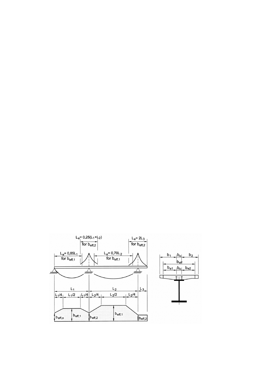
EN 1994-1-1: 2004 (E)
30
(3) The effective width of concrete flanges should be determined in accordance with the following
provisions.
(4) When elastic global analysis is used, a constant effective width may be assumed over the whole
of each span. This value may be taken as the value b
eff,1
at mid-span for a span supported at both
ends, or the value b
eff,2
at the support for a cantilever.
(5) At mid-span or an internal support, the total effective width b
eff
, see Figure 5.1, may be
determined as:
b
eff
= b
0
+
∑b
ei
(5.3)
where:
b
0
is the distance between the centres of the outstand shear connectors;
b
ei
is the value of the effective width of the concrete flange on each side of the web and
taken as L
e
/8 but not greater than the geometric width b
i
. The value b
i
should be taken
as the distance from the outstand shear connector to a point mid-way between adjacent
webs, measured at mid-depth of the concrete flange, except that at a free edge b
i
is the
distance to the free edge. The length L
e
should be taken as the approximate distance
between points of zero bending moment. For typical continuous composite beams,
where a moment envelope from various load arrangements governs the design, and for
cantilevers, L
e
may be assumed to be as shown in Figure 5.1.
(6) The effective width at an end support may be determined as:
b
eff
= b
0
+
∑
β
i
b
ei
(5.4)
with:
β
i
= (0,55 + 0,025 L
e
/ b
ei
)
≤ 1,0
(5.5)
where:
b
ei
is the effective width, see (5), of the end span at mid-span and L
e
is the equivalent span
of the end span according to Figure 5.1.
Figure 5.1 : Equivalent spans, for effective width of concrete flange

EN 1994-1-1:2004 (E)
31
(7) The distribution of the effective width between supports and midspan regions may be assumed
to be as shown in Figure 5.1.
(8) Where in buildings the bending moment distribution is influenced by the resistance or the
rotational stiffness of a joint, this should be considered in the determination of the length L
e
.
(
9) For analysis of building structures, b
0
may be taken as zero and b
i
measured from the centre of the
web.
5.4.2 Linear elastic analysis
5.4.2.1 General
(1) Allowance should be made for the effects of cracking of concrete, creep and shrinkage of
concrete, sequence of construction and pre-stressing.
5.4.2.2 Creep and shrinkage
(1)P Appropriate allowance shall be made for the effects of creep and shrinkage of concrete.
(2) Except for members with both flanges composite, the effects of creep may be taken into account
by using modular ratios n
L
for the concrete. The modular ratios depending on the type of loading
(subscript L) are given by:
(
)
t
L
0
1
ϕ
ψ
+
= n
n
L
(5.6)
where:
n
0
is the modular ratio E
a
/ E
cm
for short-term loading;
E
cm
is the secant modulus of elasticity of the concrete for short-term loading according to EN
1992-1-1, Table 3.1 or Table 11.3.1;
ϕ
t
is the creep coefficient
ϕ
(t,t
0
) according to EN 1992-1-1, 3.1.4 or 11.3.3, depending on the
age (t) of concrete at the moment considered and the age (t
0
) at loading,
ψ
L
is the creep multiplier depending on the type of loading, which be taken as 1,1 for
permanent loads, 0,55 for primary and secondary effects of shrinkage and 1,5 for pre-
stressing by imposed deformations.
(3) For permanent loads on composite structures cast in several stages one mean value t
0
may be
used for the determination of the creep coefficient. This assumption may also be used for pre-
stressing by imposed deformations, if the age of all of the concrete in the relevant spans at the time
of pre-stressing is more than 14 days.
(4) For shrinkage, the age at loading should generally be assumed to be one day.
(5) Where prefabricated slabs are used or when pre-stressing of the concrete slab is carried out
before the shear connection has become effective, the creep coefficient and the shrinkage values
from the time when the composite action becomes effective should be used.
(6) Where the bending moment distribution at t
0
is significantly changed by creep, for example in
continuous beams of mixed structures with both composite and non- composite spans, the time-
dependent secondary effects due to creep should be considered, except in global analysis for the
ultimate limit state for members where all cross-sections are in Class 1 or 2. For the time-dependent
secondary effects the modular ratio may be determined with a creep multiplier
ψ
L
of 0,55.

EN 1994-1-1: 2004 (E)
32
(7) Appropriate account should be taken of the primary and secondary effects caused by shrinkage
and creep of the concrete flange. The effects of creep and shrinkage of concrete may be neglected in
analysis for verifications of ultimate limit states other than fatigue, for composite members with all
cross-sections in Class 1 or 2 and in which no allowance for lateral-torsional buckling is necessary;
for serviceability limit states, see Section 7.
(8) In regions where the concrete slab is assumed to be cracked, the primary effects due to
shrinkage may be neglected in the calculation of secondary effects.
(9) In composite columns and compression members, account should be taken of the effects of
creep in accordance with 6.7.3.4(2).
(10) For double composite action with both flanges un-cracked (e.g. in case of pre-stressing) the
effects of creep and shrinkage should be determined by more accurate methods.
(11) For simplification in structures for buildings that satisfy expression (5.1) or 5.2.2(1), are not
mainly intended for storage and are not pre-stressed by controlled imposed deformations, the effects
of creep in composite beams may be taken into account by replacing concrete areas A
c
by effective
equivalent steel areas A
c
/n for both short-term and long-term loading, where n is the nominal
modular ratio corresponding to an effective modulus of elasticity for concrete E
c,eff
taken as E
cm
/2.
5.4.2.3
Effects of cracking of concrete
(1)P Appropriate allowance shall be made for the effects of cracking of concrete.
(2) The following method may be used for the determination of the effects of cracking in composite
beams with concrete flanges. First the envelope of the internal forces and moments for the
characteristic combinations, see EN 1990, 6.5.3, including long-term effects should be calculated
using the flexural stiffness E
a
I
1
of the un-cracked sections. This is defined as “un-cracked analysis”.
In regions where the extreme fibre tensile stress in the concrete due to the envelope of global effects
exceeds twice the strength f
ctm
or f
lctm
, see EN1992-1-1, Table 3.1 or Table 11.3.1, the stiffness
should be reduced to E
a
I
2
, see 1.5.2.12. This distribution of stiffness may be used for ultimate limit
states and for serviceability limit states. A new distribution of internal forces and moments, and
deformation if appropriate, is then determined by re-analysis. This is defined as “cracked analysis”.
(3) For continuous composite beams with the concrete flanges above the steel section and not pre-
stressed, including beams in frames that resist horizontal forces by bracing, the following simplified
method may be used. Where all the ratios of the length of adjacent continuous spans
(shorter/longer) between supports are at least 0,6, the effect of cracking may be taken into account
by using the flexural stiffness E
a
I
2
over 15% of the span on each side of each internal support, and
as the un-cracked values E
a
I
1
elsewhere.
(4) The effect of cracking of concrete on the flexural stiffness of composite columns and
compression members should be determined in accordance with 6.7.3.4.
(5) In buildings, the contribution of any encasement to a beam may be determined by using the
average of the cracked and un-cracked stiffness of the encasement. The area of concrete in
compression may be determined from the plastic stress distribution.

EN 1994-1-1:2004 (E)
33
5.4.2.4
Stages and sequence of construction
(1)P Appropriate analysis shall be made to cover the effects of staged construction including where
necessary separate effects of actions applied to structural steel and to wholly or partially composite
members.
(2) The effects of sequence of construction may be neglected in analysis for ultimate limit states
other than fatigue, for composite members where all cross-sections are in Class 1 or 2 and in which
no allowance for lateral-torsional buckling is necessary.
5.4.2.5 Temperature
effects
(1) Account should be taken of effects due to temperature in accordance with EN 1991-1-5.
(2) Temperature effects may normally be neglected in analysis for the ultimate limit states other
than fatigue, for composite members where all cross-sections are in Class 1 or Class 2 and in which
no allowance for lateral-torsional buckling is necessary.
5.4.2.6
Pre-stressing by controlled imposed deformations
(1)P Where pre-stressing by controlled imposed deformations (e.g. jacking of supports) is provided,
the effects of possible deviations from the assumed values of imposed deformations and stiffness on
the internal moments and forces shall be considered for analysis of ultimate and serviceability limit
states.
(2) Unless a more accurate method is used to determine internal moments and forces, the
characteristic values of indirect actions due to imposed deformations may be calculated with the
characteristic or nominal values of properties of materials and of imposed deformation, if the
imposed deformations are controlled.
5.4.3 Non-linear global analysis
(1) Non-linear analysis may be used in accordance with EN 1992-1-1, 5.7 and EN 1993-1-1, 5.4.3.
(2)P The behaviour of the shear connection shall be taken into account.
(
3)P Effects of the deformed geometry of the structure should be taken into account in accordance
with 5.2.
5.4.4 Linear elastic analysis with limited redistribution for buildings
(1) Provided that second-order effects need not be considered, linear elastic analysis with limited
redistribution may be applied to continuous beams and frames for verification of limit states other
than fatigue.
(2) The bending moment distribution given by a linear elastic global analysis according to 5.4.2
may be redistributed in a way that satisfies equilibrium and takes account of the effects of inelastic
behaviour of materials, and all types of buckling.
(3) Bending moments from a linear elastic analysis may be redistributed:
a) in composite beams with full or partial shear connection as given in (4) - (7);
b) in steel members in accordance with EN 1993-1-1, 5.4.1(4);
EN 1994-1-1: 2004 (E)
34
c) in concrete members subject mainly to flexure in accordance with EN 1992-1-1, 5.5;
d) in partially-encased beams without a concrete or composite slab, in accordance with (b) or
(c), whichever is the more restrictive.
(4) For ultimate limit state verifications other than for fatigue, the elastic bending moments in
composite beams may be modified according to (5) – (7) where:
–
the beam is a continuous composite member, or part of a frame that resists horizontal
forces by bracing,
–
the beam is connected by rigid and full-strength joints, or by one such joint and one
nominally-pinned joint,
–
for a partially-encased composite beam, either it is established that rotation capacity is
sufficient for the degree of redistribution adopted, or the contribution of the reinforced
concrete encasement in compression is neglected when calculating the resistance moment
at sections where the bending moment is reduced,
–
each span is of uniform depth and
–
no allowance for lateral-torsional buckling is necessary.
(5) Where (4) applies, the bending moments in composite beams determined by linear elastic global
analysis may be modified:
– by reducing maximum hogging moments by amounts not exceeding the percentages given
in Table 5.1, or
–
in beams with all cross-sections in Classes 1 or 2 only, by increasing maximum hogging
moments by amounts not exceeding 10%, for un-cracked elastic analysis or 20% for
cracked elastic analysis, see 5.4.2.3,
unless it is verified that the rotation capacity permits a higher value.
Table 5.1 : Limits to redistribution of hogging moments, per cent of the initial
value of the bending moment to be reduced
Class of cross-section in
hogging moment region
1 2 3 4
For un-cracked analysis
40
30
20
10
For cracked analysis
25
15
10
0
(6) For grades of structural steel higher than S355, redistribution should only be applied to beams
with all cross-sections in Class 1 and Class 2. Redistribution by reduction of maximum hogging
moments should not exceed 30% for an un-cracked analysis and 15% for a cracked analysis, unless
it is demonstrated that the rotation capacity permits a higher value.
(7) For composite cross-sections in Class 3 or 4, the limits in Table 5.1 relate to bending moments
assumed in design to be applied to the composite member. Moments applied to the steel member
should not be redistributed.

EN 1994-1-1:2004 (E)
35
5.4.5 Rigid plastic global analysis for buildings
(1) Rigid plastic global analysis may be used for ultimate limit state verifications other than fatigue,
where second-order effects do not have to be considered and provided that:
– all the members and joints of the frame are steel or composite;
– the steel material satisfies EN 1993-1-1, 3.2.2;
– the cross-sections of steel members satisfy EN 1993-1-1, 5.6 and
– the joints are able to sustain their plastic resistance moments for a sufficient rotation capacity.
(2) In beams and frames for buildings, it is not normally necessary to consider the effects of
alternating plasticity.
(3)P Where rigid-plastic global analysis is used, at each plastic hinge location:
a) the cross-section of the structural steel section shall be symmetrical about a plane parallel to
the plane of the web or webs;
b) the proportions and restraints of steel components shall be such that lateral-torsional buckling
does not occur;
c) lateral restraint to the compression flange shall be provided at all hinge locations at which
plastic rotation may occur under any load case;
d) the rotation capacity shall be sufficient, when account is taken of any axial compression in the
member or joint, to enable the required hinge rotation to develop and
e) where rotation requirements are not calculated, all members containing plastic hinges shall
have effective cross-sections of Class 1 at plastic hinge locations.
(4) For composite beams in buildings, the rotation capacity may be assumed to be sufficient where:
a) the grade of structural steel does not exceed S355;
b) the contribution of any reinforced concrete encasement in compression is neglected when
calculating the design resistance moment;
c) all effective cross-sections at plastic hinge locations are in Class 1; and all other effective
cross-sections are in Class 1 or Class 2;
d) each beam-to-column joint has been shown to have sufficient design rotation capacity, or to
have a design resistance moment at least 1,2 times the design plastic resistance moment of the
connected beam;
e) adjacent spans do not differ in length by more than 50% of the shorter span;
f) end spans do not exceed 115% of the length of the adjacent span;
g) in any span in which more than half of the total design load for that span is concentrated
within a length of one-fifth of the span, then at any hinge location where the concrete slab is
in compression, not more than 15% of the overall depth of the member should be in
compression; this does not apply where it can be shown that the hinge will be the last to form
in that span and
h) the steel compression flange at a plastic hinge location is laterally restrained.
(5) Unless verified otherwise, it should be assumed that composite columns do not have rotation
capacity.

EN 1994-1-1: 2004 (E)
36
(6) Where the cross-section of a steel member varies along its length, EN 1993-1-1, 5.6(3) is
applicable.
(7) Where restraint is required by (3)(c) or 4(h), it should be located within a distance along the
member from the calculated hinge location that does not exceed half the depth of the steel section.
5.5 Classification of cross-sections
5.5.1 General
(1)P The classification system defined in EN 1993-1-1, 5.5.2 applies to cross-sections of composite
beams.
(2) A composite section should be classified according to the least favourable class of its steel
elements in compression. The class of a composite section normally depends on the direction of the
bending moment at that section.
(3) A steel compression element restrained by attaching it to a reinforced concrete element may be
placed in a more favourable class, provided that the resulting improvement in performance has been
established.
(4) For classification, the plastic stress distribution should be used except at the boundary between
Classes 3 and 4, where the elastic stress distribution should be used taking into account sequence of
construction and the effects of creep and shrinkage. For classification, design values of strengths of
materials should be used. Concrete in tension should be neglected. The distribution of the stresses
should be determined for the gross cross-section of the steel web and the effective flanges.
(5) For cross-sections in Class 1 and 2 with bars in tension, reinforcement used within the effective
width should have a ductility Class B or C, see EN 1992-1-1, Table C.1. Additionally for a section
whose resistance moment is determined by 6.2.1.2, 6.2.1.3 or 6.2.1.4, a minimum area of
reinforcement A
s
within the effective width of the concrete flange should be provided to satisfy the
following condition:
A
s
≥
ρ
s
A
c
(5.7)
with
c
sk
ctm
y
s
235
k
f
f
f
δ
ρ
=
(5.8)
where:
A
c
is the effective area of the concrete flange;
f
y
is the nominal value of the yield strength of the structural steel in N/mm
2
;
f
sk
is the characteristic yield strength of the reinforcement;
f
ctm
is the mean tensile strength of the concrete, see EN1992-1-1, Table 3.1 or Table
11.3.1;
k
c
is a coefficient given in 7.4.2;
δ
is equal to 1,0 for Class 2 cross-sections, and equal to 1,1 for Class 1 cross-sections at
which plastic hinge rotation is required.
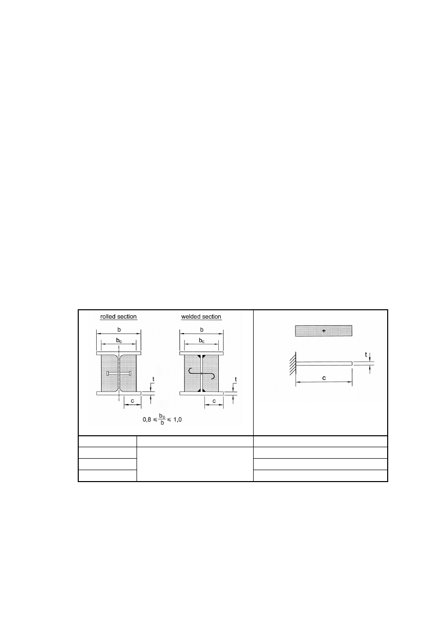
EN 1994-1-1:2004 (E)
37
(6) Welded mesh should not be included in the effective section unless it has been shown to have
sufficient ductility, when built into a concrete slab, to ensure that it will not fracture.
(7) In global analysis for stages in construction, account should be taken of the class of the steel
section at the stage considered.
5.5.2 Classification of composite sections without concrete encasement
(1) A steel compression flange that is restrained from buckling by effective attachment to a concrete
flange by shear connectors may be assumed to be in Class 1 if the spacing of connectors is in
accordance with 6.6.5.5.
(2) The classification of other steel flanges and webs in compression in composite beams without
concrete encasement should be in accordance with EN 1993-1-1, Table 5.2. An element that fails to
satisfy the limits for Class 3 should be taken as Class 4.
(3) Cross-sections with webs in Class 3 and flanges in Classes 1 or 2 may be treated as an effective
cross-section in Class 2 with an effective web in accordance with EN1993-1-1, 6.2.2.4.
5.5.3 Classification of composite sections for buildings with concrete encasement
(1) A steel outstand flange of a composite section with concrete encasement in accordance with (2)
below may be classified in accordance with Table 5.2.
Table 5.2 : Classification of steel flanges in compression for partially-encased sections
Stress distribution
(compression positive)
Class Type
Limit
1
c/t
≤ 9ε
2
c/t
≤ 14ε
3
Rolled or welded
c/t
≤ 20ε
(2) For a web of a concrete encased section, the concrete that encases it should be reinforced,
mechanically connected to the steel section, and capable of preventing buckling of the web and of
any part of the compression flange towards the web. It may be assumed that the above requirements
are satisfied if:
a) the concrete that encases a web is reinforced by longitudinal bars and stirrups, and/or welded
mesh,
b) the requirements for the ratio b
c
/ b given in Table 5.2 are fulfilled,
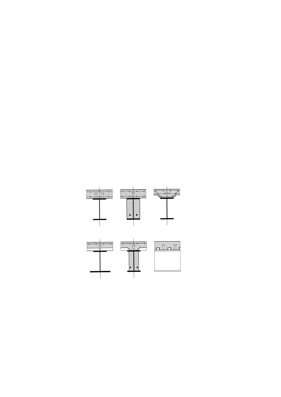
EN 1994-1-1: 2004 (E)
38
c) the concrete between the flanges is fixed to the web in accordance with Figure 6.10 by welding
the stirrups to the web or by means of bars of at least 6 mm diameter through holes and/or studs
with a diameter greater than 10 mm welded to the web and
d) the longitudinal spacing of the studs on each side of the web or of the bars through holes is not
greater than 400 mm. The distance between the inner face of each flange and the nearest row of
fixings to the web is not greater than 200 mm. For steel sections with a maximum depth of not
less than 400 mm and two or more rows of fixings, a staggered arrangement of the studs and/or
bars through holes may be used.
(3) A steel web in Class 3 encased in concrete in accordance with (2) above may be represented by
an effective web of the same cross-section in Class 2.
Section 6 Ultimate limit states
6.1 Beams
6.1.1 Beams for buildings
(1)P Composite beams are defined in 1.5.2. Typical types of cross-section are shown in Figure 6.1
with either a solid slab or a composite slab. Partially–encased beams are those in which the web of
the steel section is encased by reinforced concrete and shear connection is provided between the
concrete and the steel components.
Figure 6.1 : Typical cross-sections of composite beams
(2) Design resistances of composite cross-sections in bending or/and vertical shear should be
determined in accordance with 6.2 for composite beams with steel sections and 6.3 for partially-
encased composite beams.
(3)P Composite beams shall be checked for:
–
resistance of critical cross-sections (6.2 and 6.3);
–
resistance to lateral-torsional buckling (6.4);
–
resistance to shear buckling (6.2.2.3) and transverse forces on webs (6.5);
–
resistance to longitudinal shear (6.6).

EN 1994-1-1:2004 (E)
39
(4)P Critical cross-sections include:
– sections of maximum bending moment;
– supports;
– sections subjected to concentrated loads or reactions;
–
places where a sudden change of cross-section occurs, other than a change due to cracking
of concrete.
(5) A cross-section with a sudden change should be considered as a critical cross-section when the
ratio of the greater to the lesser resistance moment is greater than 1.2.
(6) For checking resistance to longitudinal shear, a critical length consists of a length of the
interface between two critical cross-sections. For this purpose critical cross-sections also include:
– free ends of cantilevers;
– in tapering members, sections so chosen that the ratio of the greater to the lesser plastic
resistance moments (under flexural bending of the same direction) for any pair of adjacent
cross-sections does not exceed 1.5.
(7)P The concepts "full shear connection" and "partial shear connection" are applicable only to
beams in which plastic theory is used for calculating bending resistances of critical cross-sections.
A span of a beam, or a cantilever, has full shear connection when increase in the number of shear
connectors would not increase the design bending resistance of the member. Otherwise, the shear
connection is partial.
NOTE: Limits to the use of partial shear connection are given in 6.6.1.2.
6.1.2 Effective width for verification of cross-sections
(
1) The effective width of the concrete flange for verification of cross-sections should be
determined in accordance with 5.4.1.2 taking into account the distribution of effective width
between supports and mid-span regions.
(2) As a simplification for buildings, a constant effective width may be assumed over the whole
region in sagging bending of each span. This value may be taken as the value b
eff,1
at mid-span. The
same assumption applies over the whole region in hogging bending on both sides of an intermediate
support. This value may be taken as the value b
eff,2
at the relevant support.
6.2 Resistances of cross-sections of beams
6.2.1 Bending resistance
6.2.1.1 General
(1)P The design bending resistance shall be determined by rigid-plastic theory only where the
effective composite cross-section is in Class 1 or Class 2 and where pre-stressing by tendons is not
used.
(2) Elastic analysis and non-linear theory for bending resistance may be applied to cross-sections of
any class.
(3) For elastic analysis and non-linear theory it may be assumed that the composite cross-section
remains plane if the shear connection and the transverse reinforcement are designed in accordance
with 6.6, considering appropriate distributions of design longitudinal shear force.
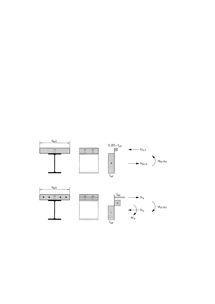
EN 1994-1-1: 2004 (E)
40
(4)P The tensile strength of concrete shall be neglected.
(5) Where the steel section of a composite member is curved in plan, the effects of curvature should
be taken into account.
6.2.1.2 Plastic resistance moment M
pl,Rd
of a composite cross-section
(1) The following assumptions should be made in the calculation of M
pl,Rd
:
a) there is full interaction between structural steel, reinforcement, and concrete;
b) the effective area of the structural steel member is stressed to its design yield strength f
yd
in tension or compression;
c) the effective areas of longitudinal reinforcement in tension and in compression are stressed
to their design yield strength f
sd
in tension or compression. Alternatively, reinforcement in
compression in a concrete slab may be neglected;
d) the effective area of concrete in compression resists a stress of 0.85 f
cd
, constant over the
whole depth between the plastic neutral axis and the most compressed fibre of the
concrete, where f
cd
is the design cylinder compressive strength of concrete.
Typical plastic stress distributions are shown in Figure 6.2.
Figure 6.2 : Examples of plastic stress distributions for a composite beam with a solid slab and
full shear connection in sagging and hogging bending
(2) For composite cross-sections with structural steel grade S420 or S460, where the distance x
pl
between the plastic neutral axis and the extreme fibre of the concrete slab in compression exceeds
15% of the overall depth h of the member, the design resistance moment M
Rd
should be taken as
β M
pl,Rd
where
β
is the reduction factor given in Figure 6.3. For values of x
pl
/h greater than 0.4 the
resistance to bending should be determined from 6.2.1.4 or 6.2.1.5.
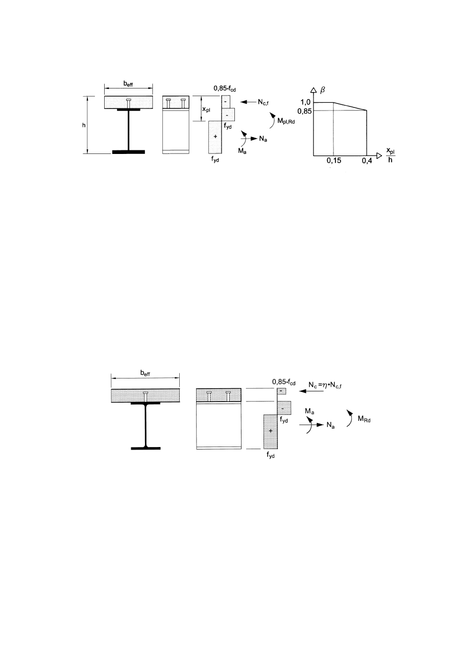
EN 1994-1-1:2004 (E)
41
Figure 6.3 : Reduction factor
β
for M
pl,Rd
(3) Where plastic theory is used and reinforcement is in tension, that reinforcement should be in
accordance with 5.5.1(5).
(4)P For buildings, profiled steel sheeting in compression shall be neglected.
(5) For buildings, any profiled steel sheeting in tension included within the effective section should
be assumed to be stressed to its design yield strength f
yp,d
.
6.2.1.3 Plastic resistance moment of sections with partial shear connection in buildings
(1) In regions of sagging bending, partial shear connection in accordance with 6.6.1 and 6.6.2.2 may
be used in composite beams for buildings.
(2) Unless otherwise verified, the plastic resistance moment in hogging bending should be
determined in accordance with 6.2.1.2 and appropriate shear connection should be provided to
ensure yielding of reinforcement in tension.
Figure 6.4 : Plastic stress distribution under sagging bending for partial shear connection
(3) Where ductile shear connectors are used, the resistance moment of the critical cross-section of
the beam M
Rd
may be calculated by means of rigid plastic theory in accordance with 6.2.1.2, except
that a reduced value of the compressive force in the concrete flange N
c
should be used in place of
the force N
cf
given by 6.2.1.2(1)(d). The ratio
η= N
c
/ N
c,f
is the degree of shear connection. The
location of the plastic neutral axis in the slab should be determined by the new force N
c
, see Figure
6.4. There is a second plastic neutral axis within the steel section, which should be used for the
classification of the web.
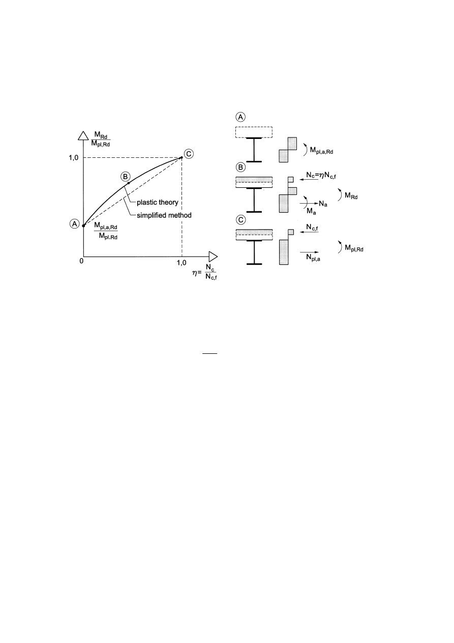
EN 1994-1-1: 2004 (E)
42
(4) The relation between M
Rd
and N
c
in (3) is qualitatively given by the convex curve ABC in
Figure 6.5 where M
pl,a,Rd
and M
pl,Rd
are the design plastic resistances to sagging bending of the
structural steel section alone, and of the composite section with full shear connection, respectively.
Figure 6.5 : Relation between M
Rd
and N
c
(for ductile shear connectors)
(5) For the method given in (3), a conservative value of M
Rd
may be determined by the straight line
AC in Figure 6.5:
(
)
cf
c
Rd
a,
pl,
Rd
pl,
Rd
a,
pl,
Rd
N
N
M
M
M
M
−
+
=
(6.1)
6.2.1.4 Non-linear resistance to bending
(1)P Where the bending resistance of a composite cross-section is determined by non-linear theory,
the stress-strain relationships of the materials shall be taken into account.
(2) It should be assumed that the composite cross-section remains plane and that the strain in
bonded reinforcement, whether in tension or compression, is the same as the mean strain in the
surrounding concrete.
(3) The stresses in the concrete in compression should be derived from the stress-strain curves given
in EN 1992-1-1, 3.1.7.
(4) The stresses in the reinforcement should be derived from the bi-linear diagrams given in
EN 1992-1-1, 3.2.7.
(5) The stresses in structural steel in compression or tension should be derived from the bi-linear
diagram given in EN 1993-1-1, 5.4.3(4) and should take account of the effects of the method of
construction (e.g. propped or un-propped).
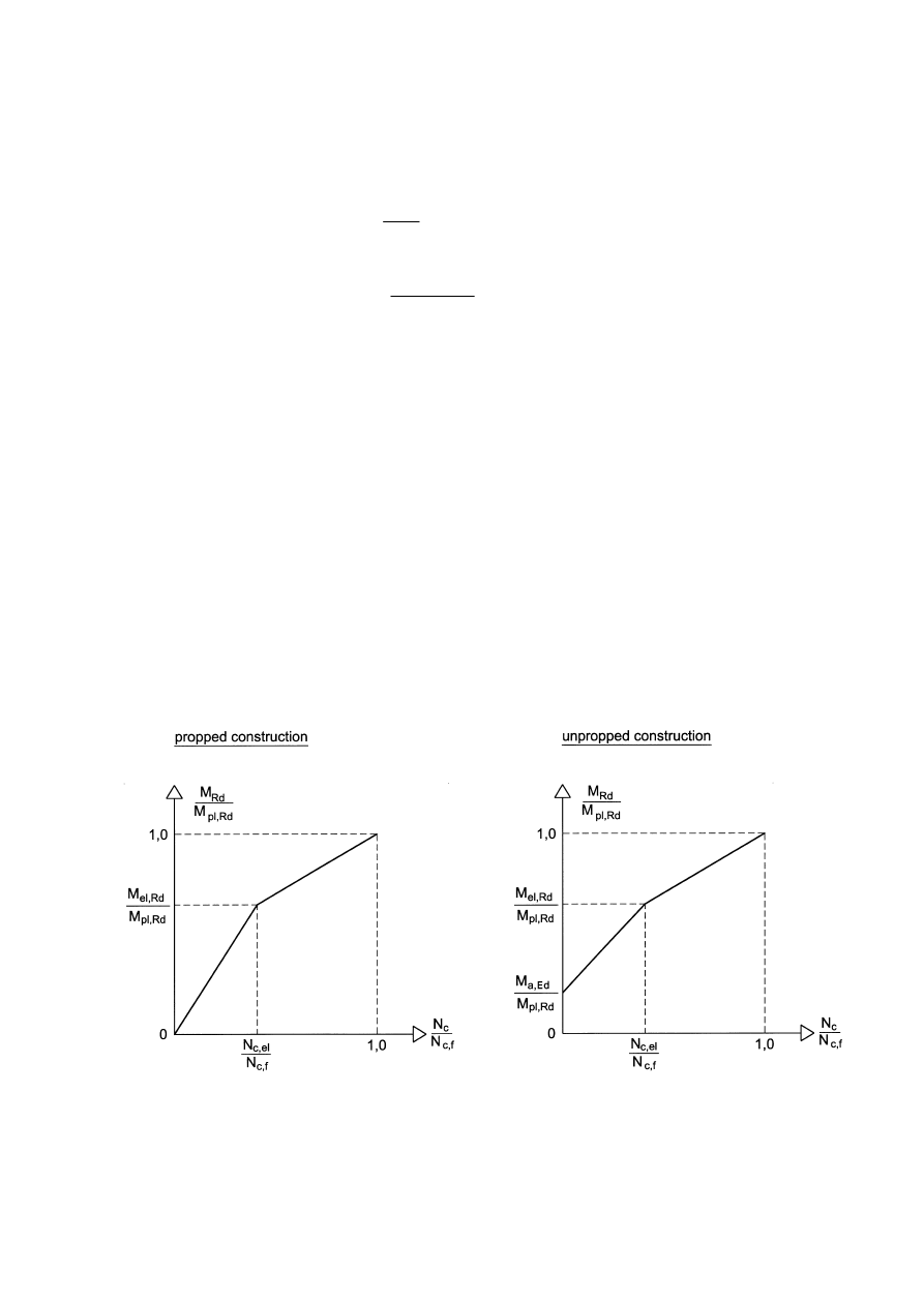
EN 1994-1-1:2004 (E)
43
(6) For Class 1 and Class 2 composite cross-sections with the concrete flange in compression, the
non-linear resistance to bending M
Rd
may be determined as a function of the compressive force in
the concrete N
c
using the simplified expressions (6.2) and (6.3), as shown in Figure 6.6:
el
c,
c
Ed
a,
Rd
el,
Ed
a,
Rd
)
(
N
N
M
M
M
M
−
+
=
for
el
c,
c
N
N
≤
(6.2)
el
c,
f
c,
el
c,
c
Rd
el,
Rd
pl,
Rd
el,
Rd
)
(
N
N
N
N
M
M
M
M
−
−
−
+
=
for
f
,
c
c
el
,
c
N
N
N
≤
≤
(6.3)
with:
M
el,Rd
=
M
a,Ed
+
k M
c,Ed
(6.4)
where:
M
a,Ed
is the design bending moment applied to the structural steel section before composite
behaviour;
M
c,Ed
is the part of the design bending moment applied to the composite section;
k
is the lowest factor such that a stress limit in 6.2.1.5(2) is reached; where un-propped
construction is used, the sequence of construction should be taken into account;
el
,
c
N
is the compressive force in the concrete flange corresponding to moment M
el,Rd
.
For cross sections where 6.2.1.2 (2) applies, in expression (6.3) and in Figure 6.6 instead of M
pl,Rd
the reduced value
β
M
pl,Rd
should be used.
(7) For buildings, the determination of M
el.Rd
may be simplified using 5.4.2.2(11).
Figure 6.6 : Simplified relationship between M
Rd
and N
c
for sections with the concrete slab in
compression

EN 1994-1-1: 2004 (E)
44
6.2.1.5 Elastic resistance to bending
(1) Stresses should be calculated by elastic theory, using an effective width of the concrete flange in
accordance with 6.1.2. For cross-sections in Class 4, the effective structural steel section should be
determined in accordance with EN 1993-1-5, 4.3.
(2) In the calculation of the elastic resistance to bending based on the effective cross-section, the
limiting stresses should be taken as:
– f
cd
in concrete in compression;
–
f
yd
in structural steel in tension or compression;
–
f
sd
in reinforcement in tension or compression. Alternatively, reinforcement in
compression in a concrete slab may be neglected.
(3)P Stresses due to actions on the structural steelwork alone shall be added to stresses due to
actions on the composite member.
(4) Unless a more precise method is used, the effect of creep should be taken into account by use of
a modular ratio according to 5.4.2.2.
(5) In cross-sections with concrete in tension and assumed to be cracked, the stresses due to primary
(isostatic) effects of shrinkage may be neglected.
6.2.2 Resistance to vertical shear
6.2.2.1 Scope
(1) Clause 6.2.2 applies to composite beams with a rolled or welded structural steel section with a
solid web, which may be stiffened.
6.2.2.2 Plastic resistance to vertical shear
(1) The resistance to vertical shear
V
pl,Rd
should be taken as the resistance of the structural steel
section V
pl,a,Rd
unless the value for a contribution from the reinforced concrete part of the beam has
been established.
(2) The design plastic shear resistance
V
pl,a,Rd
of the structural steel section should be determined in
accordance with EN 1993-1-1, 6.2.6.
6.2.2.3 Shear buckling resistance
(1) The shear buckling resistance
V
b,Rd
of an uncased steel web should be determined in accordance
with EN 1993-1-5, 5.
(2) No account should be taken of a contribution from the concrete slab, unless a more precise
method than the one of EN 1993-1-5, 5 is used and unless the shear connection is designed for the
relevant vertical force.
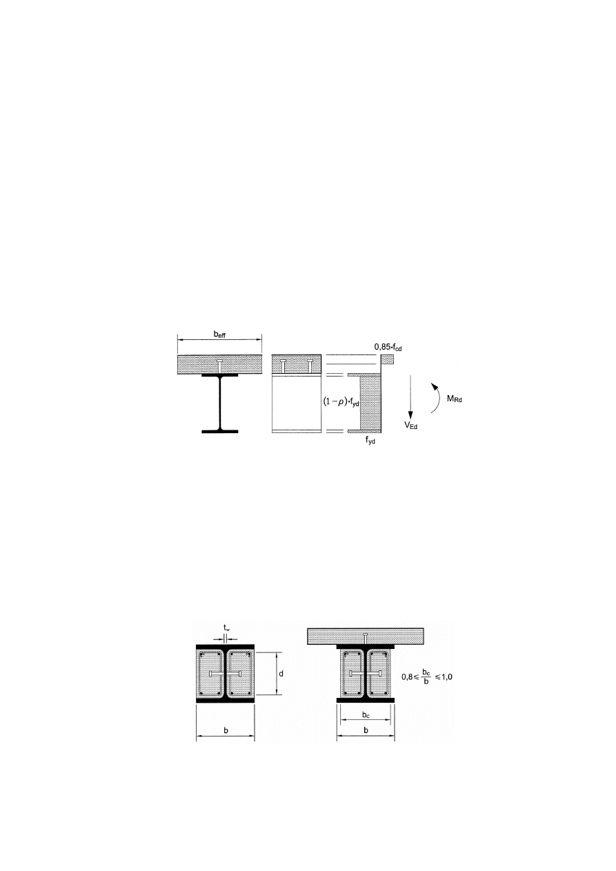
EN 1994-1-1:2004 (E)
45
6.2.2.4 Bending and vertical shear
(1) Where the vertical shear force
V
Ed
exceeds half the shear resistance
V
Rd
given by
V
pl,Rd
in 6.2.2.2
or V
b,Rd
in 6.2.2.3, whichever is the smaller, allowance should be made for its effect on the
resistance moment.
(2) For cross-sections in Class 1 or 2, the influence of the vertical shear on the resistance to bending
may be taken into account by a reduced design steel strength (1 -
ρ
)
f
yd
in the shear area as shown
in Figure 6.7 where:
ρ
= (2V
Ed
/
V
Rd
– 1)
2
(6.5)
and
V
Rd
is the appropriate resistance to vertical shear, determined in accordance with 6.2.2.2 or
6.2.2.3.
(3) For cross-sections in Class 3 and 4, EN 1993-1-5, 7.1 is applicable using the calculated stresses
of the composite section.
Figure 6.7 : Plastic stress distribution modified by the effect of vertical shear
6.3
Resistance of cross-sections of beams for buildings with partial encasement
6.3.1 Scope
(1) Partially–encased beams are defined in 6.1.1(1). A concrete or composite slab can also form part
of the effective section of the composite beam, provided that it is attached to the steel section by a
shear connection in accordance with 6.6. Typical cross-sections are shown in Figure 6.8.
(2) Clause 6.3 is applicable to partially encased sections in Class 1 or Class 2, provided that d/t
w
is
not greater than 124
ε
.
Figure 6.8 : Typical cross-sections of partially-encased beams
(3) The provisions elsewhere in EN 1994-1-1 are applicable, unless different rules are given in 6.3.
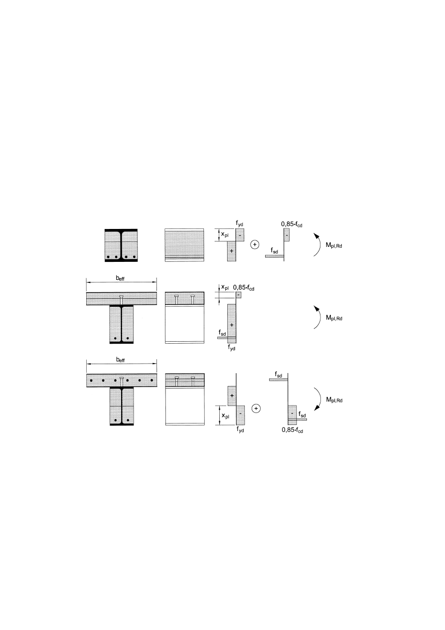
EN 1994-1-1: 2004 (E)
46
6.3.2 Bending resistance
(1) Full shear connection should be provided between the structural steel section and the web
encasement in accordance with 6.6.
(2) The design resistance moment may be determined by plastic theory. Reinforcement in
compression in the concrete encasement may be neglected. Some examples of typical plastic stress
distributions are shown in Figure 6.9.
(3) Partial shear connection may be used for the compressive force in any concrete or composite
slab forming part of the effective section.
(4) Where partial shear connection is used with ductile connectors, the plastic resistance moment of
the beam should be calculated in accordance with 6.3.2(2) and 6.2.1.2(1), except that a reduced
value of the compressive force in the concrete or composite slab N
c
should be used as in 6.2.1.3(3),
(4) and (5).
Figure 6.9 : Examples of plastic stress distributions for effective sections
6.3.3 Resistance to vertical shear
(1) The design shear resistance of the structural steel section
V
pl,a,Rd
should be determined by plastic
theory in accordance with 6.2.2.2(2).
(2) The contribution of the web encasement to shear may be taken into account for the
determination of the design shear resistance of the cross-section if stirrups are used in accordance
with Figure 6.10. Appropriate shear connection should be provided between the encasement and the
structural steel section. If the stirrups of the encasement are open, they should be attached to the
web by full strength welds. Otherwise the contribution of the shear reinforcement should be
neglected.

EN 1994-1-1:2004 (E)
47
(3) Unless a more accurate analysis is used, the distribution of the total vertical shear
V
Ed
into the
parts V
a,Ed
and
V
c,Ed
, acting on the steel section and the reinforced concrete web encasement
respectively, may be assumed to be in the same ratio as the contributions of the steel section and the
reinforced web encasement to the bending resistance M
pl,Rd
.
(4) The resistance to vertical shear for the web encasement should take account of cracking of
concrete and should be verified in accordance with EN 1992-1-1, 6.2 and the other relevant design
requirements of that Standard.
Figure 6.10 : Arrangement of stirrups
6.3.4 Bending and vertical shear
(1) Where the design vertical shear force
V
a,Ed
exceeds half the design plastic resistance
V
pl,a,Rd
of
the structural steel section to vertical shear, allowance should be made for its effect on the
resistance moment.
(2) The influence of the vertical shear on the resistance to bending may be expressed as in 6.2.2.4(2)
with the following modification. In expression (6.5), the ratio V
Ed
/
V
pl,Rd
is replaced by
V
a,Ed
/
V
pl,a,Rd
to calculate the reduced design steel strength in the shear area of the structural steel section. Then,
the design reduced plastic resistance moment M
Rd
should be calculated in accordance with 6.3.2.
6.4 Lateral-torsional buckling of composite beams
6.4.1 General
(1) A steel flange that is attached to a concrete or composite slab by shear connection in accordance
with 6.6 may be assumed to be laterally stable, provided that lateral instability of the concrete slab
is prevented.
(2) All other steel flanges in compression should be checked for lateral stability.
(3) The methods in EN 1993-1-1, 6.3.2.1-6.3.2.3 and, more generally, 6.3.4 are applicable to the
steel section on the basis of the cross-sectional forces on the composite section, taking into account
effects of sequence of construction in accordance with 5.4.2.4. The lateral and elastic torsional
restraint at the level of the shear connection to the concrete slab may be taken into account.
(4) For composite beams in buildings with cross-sections in Class 1, 2 or 3 and of uniform
structural steel section, the method given in 6.4.2 may be used.

EN 1994-1-1: 2004 (E)
48
6.4.2 Verification of lateral-torsional buckling of continuous composite beams with cross-
sections in Class 1, 2 and 3 for buildings
(1) The design buckling resistance moment of a laterally unrestrained continuous composite beam
(or a beam within a frame that is composite throughout its length) with Class 1, 2 or 3 cross-
sections and with a uniform structural steel section should be taken as:
Rd
LT
Rd
b,
M
M
χ
=
(6.6)
where:
LT
χ
is the reduction factor for lateral-torsional buckling depending on the relative
slenderness
LT
λ ;
M
Rd
is the design resistance moment under hogging bending at the relevant internal support
(or beam-to-column joint).
Values of the reduction factor
LT
χ
may be obtained from EN 1993-1-1, 6.3.2.2 or 6.3.2.3.
(2) For cross-sections in Class 1 or 2,
M
Rd
should be determined according to 6.2.1.2 for a beam
whose bending resistance is based on plastic theory, or 6.2.1.4 for a beam whose bending resistance
is based on non-linear theory, or 6.3.2 for a partially-encased beam, with f
yd
determined using the
partial factor
γ
M1
given by EN 1993-1-1, 6.1(1).
(3) For cross-sections in Class 3, M
Rd
should be determined using expression (6.4), but as the design
hogging bending moment that causes either a tensile stress f
s
d
in the reinforcement or a compression
stress f
yd
in the extreme bottom fibre of the steel section, whichever is the smaller;
f
yd
should be
determined using the partial factor
γ
M1
given by EN 1993-1-1, 6.1(1).
(4) The relative slenderness
LT
λ may be calculated by:
LT
λ
cr
Rk
M
M
=
(6.7)
where:
M
Rk
is the resistance moment of the composite section using the characteristic material
properties;
M
cr
is the elastic critical moment for lateral-torsional buckling determined at the internal
support of the relevant span where the hogging bending moment is greatest.
(5) Where the same slab is also attached to one or more supporting steel members approximately
parallel to the composite beam considered and the conditions 6.4.3(c), (e) and (f) are satisfied, the
calculation of the elastic critical moment M
cr
may be based on the "continuous inverted U-frame"
model. As shown in Figure 6.11, this model takes into account the lateral displacement of the
bottom flange causing bending of the steel web, and the rotation of the top flange that is resisted by
bending of the slab.
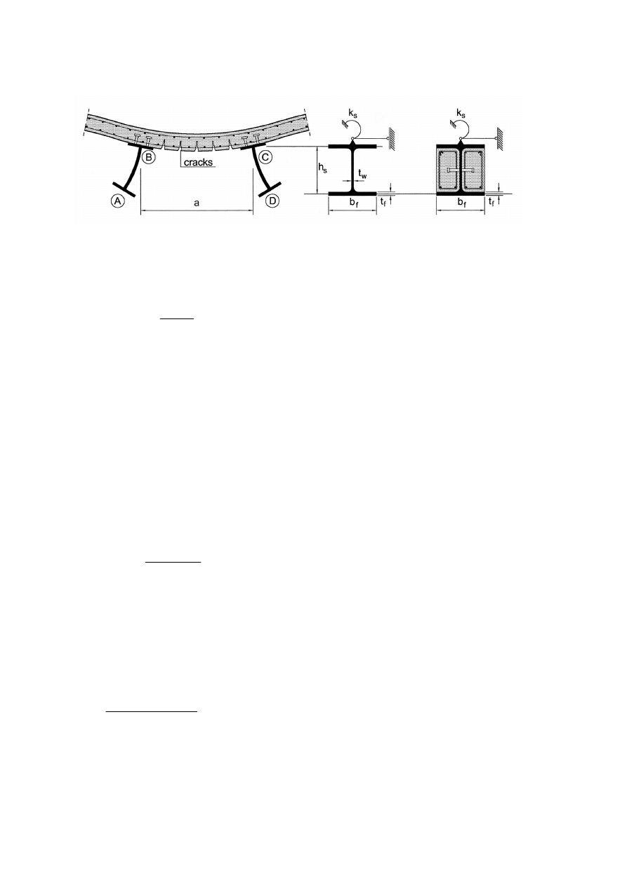
EN 1994-1-1:2004 (E)
49
Figure 6.11 : Inverted-U frame ABCD resisting lateral-torsional buckling
(6) At the level of the top steel flange, a rotational stiffness k
s
per unit length of steel beam may be
adopted to represent the U-frame model by a beam alone:
2
1
2
1
s
k
k
k
k
k
+
=
(6.8)
where:
k
1
is the flexural stiffness of the cracked concrete or composite slab in the direction transverse
to the steel beam, which may be taken as:
k
1
=
α
(
EI)
2
/
a
(6.9)
where
α
= 2 for
k
1
for an edge beam, with or without a cantilever, and
α
= 3 for an inner
beam. For inner beams in a floor with four or more similar beams,
α
= 4 may be used;
a
is the spacing between the parallel beams;
(EI)
2
is the "cracked" flexural stiffness per unit width of the concrete or composite slab, taken as
the lower of the value at mid-span, for sagging bending, and the value at the supporting steel
section, for hogging bending;
k
2
is the flexural stiffness of the steel web, to be taken as:
s
2
a
3
w
a
2
)
1
(
4
h
t
E
k
ν
−
=
(6.10)
for an uncased steel beam,
where :
a
ν
is Poisson’s ratio for structural steel and
h
s
and
t
w
are defined in Figure 6.11.
(7) For a steel beam with partial encasement in accordance with 5.5.3(2), the flexural stiffness
k
2
may take account of the encasement and be calculated by:
)
/
4
1
(
16
c
w
s
2
c
w
a
2
b
t
n
h
b
t
E
k
+
=
(6.11)
where:
n
is the modular ratio for long-term effects according to 5.4.2.2, and
b
c
is the width of the concrete encasement, see Figure 6.8.

EN 1994-1-1: 2004 (E)
50
(8) In the U-frame model, the favourable effect of the St. Venant torsional stiffness G
a
I
at
of the steel
section may be taken into account for the calculation of M
cr
.
(9) For a partially-encased steel beam with encasement reinforced either with open stirrups attached
to the web or with closed stirrups, the torsional stiffness of the encasement may be added to the
value G
a
I
at
for the steel section. This additional torsional stiffness should be taken as G
c
I
ct
/10,
where G
c
is the shear modulus for concrete, which may be taken as 0,3E
a
/ n (where n is the modular
ratio for long-term effects), and I
ct
is the St. Venant torsion constant of the encasement, assuming it
to be un-cracked and of breadth equal to the overall width of the encasement.
6.4.3 Simplified verification for buildings without direct calculation
(1) A continuous beam (or a beam within a frame that is composite throughout its length) with
Class 1, 2 or 3 cross-sections may be designed without additional lateral bracing when the
following conditions are satisfied:
a) Adjacent spans do not differ in length by more than 20% of the shorter span. Where there
is a cantilever, its length does not exceed 15% of that of the adjacent span.
b) The loading on each span is uniformly distributed, and the design permanent load exceeds
40% of the total design load.
c) The top flange of the steel member is attached to a reinforced concrete or composite slab
by shear connectors in accordance with 6.6.
d) The same slab is also attached to another supporting member approximately parallel to the
composite beam considered, to form an inverted-U frame as illustrated in Figure 6.11.
e) If the slab is composite, it spans between the two supporting members of the inverted-U
frame considered.
f) At each support of the steel member, its bottom flange is laterally restrained and its web is
stiffened. Elsewhere, the web may be un-stiffened.
g) If the steel member is an IPE section or an HE section that is not partially encased, its
depth h does not exceed the limit given in Table 6.1.
h)
If the steel member is partially encased in concrete according to 5.5.3(2), its depth h does
not exceed the limit given in Table 6.1 by more than 200 mm for steel grades up to S355
and by 150 mm for grades S420 and S460.
NOTE: Provisions for other types of steel section may be given in the National Annex.
Table 6.1 : Maximum depth h (mm) of uncased steel member for which clause 6.4.3 is
applicable
Nominal steel grade
Steel member
S 235
S 275
S 355
S 420 and S 460
IPE
600
550
400
270
HE
800
700
650
500

EN 1994-1-1:2004 (E)
51
6.5 Transverse forces on webs
6.5.1 General
(1) The rules given in EN 1993-1-5, 6 to determine the design resistance of an unstiffened or
stiffened web to transverse forces applied through a flange are applicable to the non-composite steel
flange of a composite beam, and to the adjacent part of the web.
(2) If the transverse force acts in combination with bending and axial force, the resistance should be
verified according to EN 1993-1-5, 7.2.
(3) For buildings, at an internal support of a beam designed using an effective web in Class 2 in
accordance with 5.5.2(3), transverse stiffening should be provided unless it has been verified that
the un-stiffened web has sufficient resistance to crippling and buckling.
6.5.2 Flange-induced buckling of webs
(1) EN 1993-1-5, 8 is applicable provided that area A
fc
is taken equal to the area of the non-
composite steel flange or the transformed area of the composite steel flange taking into account the
modular ratio for short-term loading, whichever is the smaller.
6.6 Shear connection
6.6.1 General
6.6.1.1 Basis of design
(
1) Clause 6.6 is applicable to composite beams and, as appropriate, to other types of composite
member.
(2)P Shear connection and transverse reinforcement shall be provided to transmit the longitudinal
shear force between the concrete and the structural steel element, ignoring the effect of natural bond
between the two.
(3)P Shear connectors shall have sufficient deformation capacity to justify any inelastic
redistribution of shear assumed in design.
(4)P Ductile connectors are those with sufficient deformation capacity to justify the assumption of
ideal plastic behaviour of the shear connection in the structure considered.
(5) A connector may be taken as ductile if the characteristic slip capacity
δ
uk
is at least 6mm.
NOTE
: An evaluation of
δ
uk
is given in Annex B.
(6)P Where two or more different types of shear connection are used within the same span of a
beam, account shall be taken of any significant difference in their load-slip properties.
(7)P Shear connectors shall be capable of preventing separation of the concrete element from the
steel element, except where separation is prevented by other means.
(8) To prevent separation of the slab, shear connectors should be designed to resist a nominal
ultimate tensile force, perpendicular to the plane of the steel flange, of at least 0,1 times the design
ultimate shear resistance of the connectors. If necessary they should be supplemented by anchoring
devices.

EN 1994-1-1: 2004 (E)
52
(9) Headed stud shear connectors in accordance with 6.6.5.7 may be assumed to provide sufficient
resistance to uplift, unless the shear connection is subjected to direct tension.
(10)P Longitudinal shear failure and splitting of the concrete slab due to concentrated forces applied
by the connectors shall be prevented.
(11) If the detailing of the shear connection is in accordance with the appropriate provisions of 6.6.5
and the transverse reinforcement is in accordance with 6.6.6, compliance with 6.6.1.1(10) may be
assumed.
(12) Where a method of interconnection, other than the shear connectors included in 6.6, is used to
transfer shear between a steel element and a concrete element, the behaviour assumed in design
should be based on tests and supported by a conceptual model. The design of the composite
member should conform to the design of a similar member employing shear connectors included in
6.6, in so far as practicable.
(13) For buildings, the number of connectors should be at least equal to the total design shear force
for the ultimate limit state, determined according to 6.6.2, divided by the design resistance of a
single connector P
Rd
. For stud connectors the design resistance should be determined according to
6.6.3 or 6.6.4, as appropriate.
(14)P If all cross-sections are in Class 1 or Class 2, in buildings partial shear connection may be
used for beams. The number of connectors shall then be determined by a partial connection theory
taking into account the deformation capacity of the shear connectors.
6.6.1.2 Limitation on the use of partial shear connection in beams for buildings
(1) Headed studs with an overall length after welding not less than 4 times the diameter, and with a
shank of nominal diameter not less than 16 mm and not greater than 25 mm, may be considered as
ductile within the following limits for the degree of shear connection, which is defined by the ratio
η
= n / n
f
:
For steel sections with equal flanges:
L
e
≤ 25:
η
≥ 1 –
y
355
f
(0,75 – 0,03 L
e
),
η
≥ 0,4
(6.12)
L
e
> 25:
η
≥ 1
(6.13)
For steel sections having a bottom flange with an area equal to three times the area of the top
flange:
L
e
≤ 20:
η
≥ 1 –
y
355
f
(0,30 – 0,015 L
e
),
η
≥ 0,4
(6.14)
L
e
> 20:
η
≥ 1
(6.15)
where:
L
e
is the distance in sagging bending between points of zero bending moment in metres; for
typical continuous beams, L
e
may be assumed to be as shown in Figure 5.1;

EN 1994-1-1:2004 (E)
53
n
f
is the number of connectors for full shear connection determined for that length of beam
in accordance with 6.6.1.1(13) and 6.6.2.2(2);
n
is the number of shear connectors provided within that same length.
(2) For steel sections having a bottom flange with an area exceeding the area of the top flange but
less than three times that area, the limit for
η
may be determined from expressions (6.12) – (6.15)
by linear interpolation.
(3) Headed stud connectors may be considered as ductile over a wider range of spans than given in
(1) above where:
(a)
the studs have an overall length after welding not less than 76 mm, and a shank of
nominal diameter of 19 mm,
(b)
the steel section is a rolled or welded I or H with equal flanges,
(c)
the concrete slab is composite with profiled steel sheeting that spans perpendicular to the
beam and the concrete ribs are continuous across it,
(d)
there is one stud per rib of sheeting, placed either centrally within the rib or alternately
on the left side and on the right side of the trough throughout the length of the span,
(e)
for the sheeting b
0
/ h
p
≥ 2 and h
p
≤ 60 mm, where the notation is as in Figure 6.13 and
(f)
the force N
c
is calculated in accordance with the simplified method given in Figure 6.5.
Where these conditions are satisfied, the ratio
η
should satisfy:
L
e
≤ 25:
η
≥ 1 –
y
355
f
(1,0 – 0,04 L
e
),
η
≥ 0,4
(6.16)
L
e
> 25:
η
≥ 1
(6.17)
NOTE
: The requirements in 6.6.1.2 are derived for uniform spacing of shear connectors.
6.6.1.3 Spacing of shear connectors in beams for buildings
(1)P The shear connectors shall be spaced along the beam so as to transmit longitudinal shear and to
prevent separation between the concrete and the steel beam, considering an appropriate distribution
of design longitudinal shear force.
(2) In cantilevers and hogging moment regions of continuous beams, tension reinforcement should
be curtailed to suit the spacing of the shear connectors and should be adequately anchored.
(3) Ductile connectors may be spaced uniformly over a length between adjacent critical cross-
sections as defined in 6.1.1 provided that:
–
all critical sections in the span considered are in Class 1 or Class 2;
–
η
satisfies the limit given by 6.6.1.2 and
–
the plastic resistance moment of the composite section does not exceed 2,5 times the
plastic resistance moment of the steel member alone.

EN 1994-1-1: 2004 (E)
54
(4) If the plastic resistance moment exceeds 2,5 times the plastic resistance moment of the steel
member alone, additional checks on the adequacy of the shear connection should be made at
intermediate points approximately mid-way between adjacent critical cross-sections.
(5) The required number of shear connectors may be distributed between a point of maximum
sagging bending moment and an adjacent support or point of maximum hogging moment, in
accordance with the longitudinal shear calculated by elastic theory for the loading considered.
Where this is done, no additional checks on the adequacy of the shear connection are required.
6.6.2 Longitudinal shear force in beams for buildings
6.6.2.1 Beams in which non-linear or elastic theory is used for resistances of one or more cross-
sections
(1) If non-linear or elastic theory is applied to cross-sections, the longitudinal shear force should be
determined in a manner consistent with 6.2.1.4 or 6.2.1.5 respectively.
6.6.2.2 Beams in which plastic theory is used for resistance of cross sections
(1)P The total design longitudinal shear shall be determined in a manner consistent with the design
bending resistance, taking account of the difference in the normal force in concrete or structural
steel over a critical length.
(2) For full shear connection, reference should be made to 6.2.1.2, or 6.3.2, as appropriate.
(3) For partial shear connection, reference should be made to 6.2.1.3 or 6.3.2, as appropriate.
6.6.3 Headed stud connectors in solid slabs and concrete encasement
6.6.3.1 Design resistance
(1) The design shear resistance of a headed stud automatically welded in accordance with EN 14555
should be determined from:
V
2
u
Rd
4
/
8
,
0
γ
π
d
f
P
=
(6.18)
or:
V
cm
ck
2
Rd
29
,
0
γ
α
E
f
d
P
=
(6.19)
whichever is smaller, with:
+
=
1
2
,
0
sc
d
h
α
for 3
≤ h
sc
/ d
≤ 4
(6.20)
1
=
α
for h
sc
/ d > 4
(6.21)
where:
γ
V
is the partial factor;
d
is the diameter of the shank of the stud, 16 mm
≤ d ≤ 25 mm;
f
u
is the specified ultimate tensile strength of the material of the stud but not greater than
500 N/mm2;
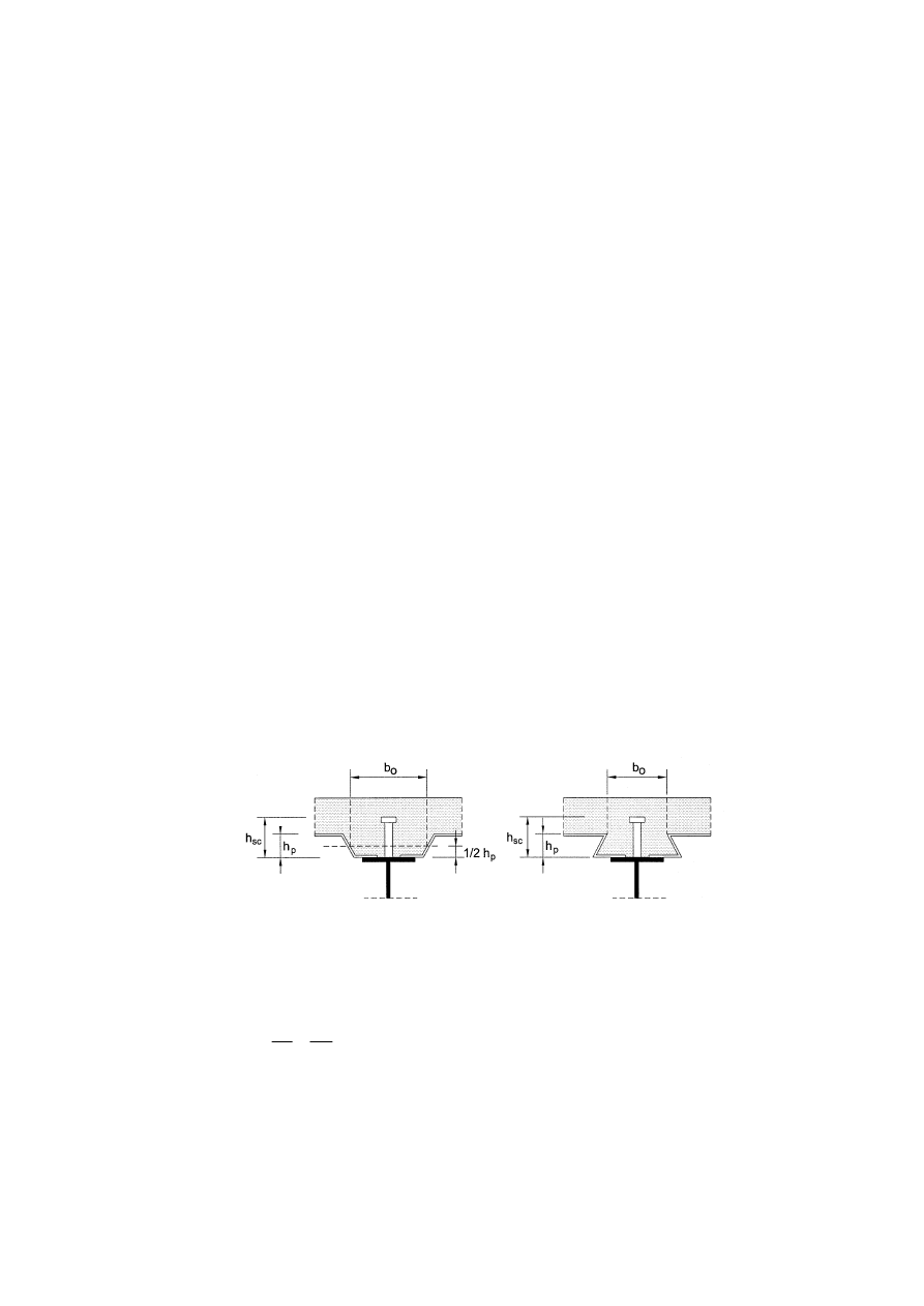
EN 1994-1-1:2004 (E)
55
f
ck
is the characteristic cylinder compressive strength of the concrete at the age considered,
of density not less than 1750 kg/m
3
;
h
sc
is the overall nominal height of the stud.
NOTE: The value for
γV may be given in the National Annex. The recommended value for γV is 1,25.
(2) The weld collars should comply with the requirements of EN 13918.
(3) Where studs are arranged in a way such that splitting forces occur in the direction of the slab
thickness, (1) is not applicable.
NOTE: For buildings, further information may be given in the National Annex.
6.6.3.2 Influence of tension on shear resistance
(1) Where headed stud connectors are subjected to direct tensile force in addition to shear, the
design tensile force per stud F
ten
should be calculated.
(2) If F
ten
≤ 0,1P
Rd
, where P
Rd
is the design shear resistance defined in 6.6.3.1, the tensile force
may be neglected.
(3) If F
ten
> 0,1P
Rd
, the connection is not within the scope of EN 1994.
6.6.4 Design resistance of headed studs used with profiled steel sheeting in buildings
6.6.4.1 Sheeting with ribs parallel to the supporting beams
(1) The studs are located within a region of concrete that has the shape of a haunch, see Figure 6.12.
Where the sheeting is continuous across the beam, the width of the haunch b
0
is equal to the width
of the trough as given in Figure 9.2. Where the sheeting is not continuous, b
0
is defined in a similar
way as given in Figure 6.12. The depth of the haunch should be taken as h
p
, the overall depth of the
sheeting excluding embossments.
Figure 6.12 : Beam with profiled steel sheeting parallel to the beam
(2) The design shear resistance should be taken as the resistance in a solid slab, see 6.6.3.1,
multiplied by the reduction factor k
l
given by the following expression:
0
,
1
1
6
,
0
p
sc
p
0
≤
−
=
h
h
h
b
k
l
(6.22)
where h
sc
is the overall height of the stud, but not greater than h
p
+ 75 mm.
(3) Where the sheeting is not continuous across the beam, and is not appropriately anchored to the
beam, that side of the haunch and its reinforcement should satisfy 6.6.5.4.
NOTE: Means to achieve appropriate anchorage may be given in the National Annex.
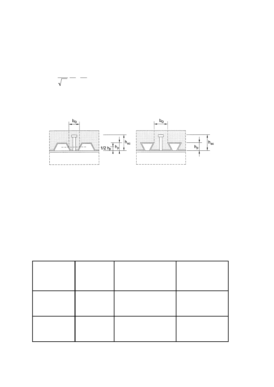
EN 1994-1-1: 2004 (E)
56
6.6.4.2 Sheeting with ribs transverse to the supporting beams
(1) Provided that the conditions given in (2) and (3) are satisfied, the design shear resistance should
be taken as the resistance in a solid slab, calculated as given by 6.6.3.1 (except that f
u
should not be
taken as greater than 450 N/mm
2
) multiplied by the reduction factor k
t
given by:
−
=
1
7
,
0
p
sc
p
0
r
t
h
h
h
b
n
k
(6.23)
where:
n
r
is the number of stud connectors in one rib at a beam intersection, not to exceed 2 in
computations, and other symbols are as defined in Figure 6.13.
Figure 6.13 : Beam with profiled steel sheeting transverse to the beam
(2) The factor k
t
should not be taken greater than the appropriate value k
t,max
given in Table 6.2.
(3) The values for kt given by (1) and (2) are applicable provided that:
– the studs are placed in ribs with a height h
p
not greater than 85 mm and a width b
0
not less
than h
p
and
– for through deck welding, the diameter of the studs is not greater than 20mm, or
– for holes provided in the sheeting, the diameter of the studs is not greater than 22mm.
Table 6.2 : Upper limits kt,max for the reduction factor kt
Number of stud
connectors per
rib
Thickness t of
sheet
(mm)
Studs not exceeding 20
mm in diameter and
welded through profiled
steel sheeting
Profiled sheeting
with holes and studs
19 mm or 22mm in
diameter
≤ 1,0
0,85 0,75
n
r
= 1
> 1,0
1,0
0,75
≤ 1,0
0,70 0,60
n
r
= 2
> 1,0
0,8
0,60

EN 1994-1-1:2004 (E)
57
6.6.4.3 Biaxial loading of shear connectors
(1) Where the shear connectors are provided to produce composite action both for the beam and for
the composite slab, the combination of forces acting on the stud should satisfy the following:
1
2
Rd
t,
2
t
2
Rd
,
2
≤
+
P
F
P
F
l
l
(6.24)
where:
F
l
is the design longitudinal force caused by composite action in the beam;
F
t
is the design transverse force caused by composite action in the slab, see Section 9;
P
l
,Rd
and P
t,Rd
are the corresponding design shear resistances of the stud.
6.6.5 Detailing of the shear connection and influence of execution
6.6.5.1 Resistance to separation
(1) The surface of a connector that resists separation forces (for example, the underside of the head
of a stud) should extend not less than 30 mm clear above the bottom reinforcement, see Figure 6.14.
6.6.5.2 Cover and concreting for buildings
(1)P The detailing of shear connectors shall be such that concrete can be adequately compacted
around the base of the connector.
(2) If cover over the connector is required, the nominal cover should be:
a) not less than 20 mm, or
b) as recommended by EN 1992-1-1, Table 4.4 for reinforcing steel, less 5 mm,
whichever is the greater.
(3) If cover is not required the top of the connector may be flush with the upper surface of the
concrete slab.
(4) In execution, the rate and sequence of concreting should be required to be such that partly
matured concrete is not damaged as a result of limited composite action occurring from deformation
of the steel beams under subsequent concreting operations. Wherever possible, deformation should
not be imposed on a shear connection until the concrete has reached a cylinder strength of at least
20 N/mm
2
.
6.6.5.3 Local reinforcement in the slab
(1) Where the shear connection is adjacent to a longitudinal edge of a concrete slab, transverse
reinforcement provided in accordance with 6.6.6 should be fully anchored in the concrete between
the edge of the slab and the adjacent row of connectors.
(2) To prevent longitudinal splitting of the concrete flange caused by the shear connectors, the
following additional recommendations should be applied where the distance from the edge of the
concrete flange to the centreline of the nearest row of shear connectors is less than 300 mm:
a) transverse reinforcement should be supplied by U-bars passing around the shear
connectors,
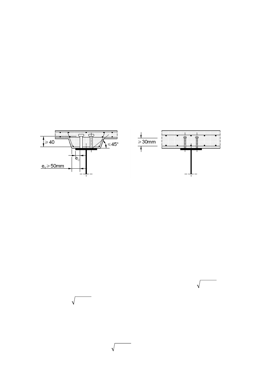
EN 1994-1-1: 2004 (E)
58
b) where headed studs are used as shear connectors, the distance from the edge of the
concrete flange to the centre of the nearest stud should not be less than 6d, where d is the
nominal diameter of the stud, and the U-bars should be not less than 0,5d in diameter and
c) the U-bars should be placed as low as possible while still providing sufficient bottom
cover.
(3)P At the end of a composite cantilever, sufficient local reinforcement shall be provided to
transfer forces from the shear connectors to the longitudinal reinforcement.
6.6.5.4 Haunches other than formed by profiled steel sheeting
(1) Where a concrete haunch is used between the steel section and the soffit of the concrete slab, the
sides of the haunch should lie outside a line drawn at 45
o
from the outside edge of the connector,
see Figure 6.14.
Figure 6.14 : Detailing
(2) The nominal concrete cover from the side of the haunch to the connector should be not less than
50 mm.
(3) Transverse reinforcing bars sufficient to satisfy the requirements of 6.6.6 should be provided in
the haunch at not less than 40 mm clear below the surface of the connector that resists uplift.
6.6.5.5 Spacing of connectors
(1)P Where it is assumed in design that the stability of either the steel or the concrete member is
ensured by the connection between the two, the spacing of the shear connectors shall be sufficiently
close for this assumption to be valid.
(2) Where a steel compression flange that would otherwise be in a lower class is assumed to be in
Class 1 or Class 2 because of restraint from shear connectors, the centre-to-centre spacing of the
shear connectors in the direction of compression should be not greater than the following limits:
–
where the slab is in contact over the full length (e.g. solid slab): 22 t
f
y
/
235 f
–
where the slab is not in contact over the full length (e.g. slab with ribs transverse to the
beam): 15 t
f
y
/
235 f
where:
t
f
is the thickness of the flange;
f
y
is the nominal yield strength of the flange in N/mm
2
.
In addition, the clear distance from the edge of a compression flange to the nearest line of shear
connectors should be not greater than 9 t
f
y
/
235 f .

EN 1994-1-1:2004 (E)
59
(3) In buildings, the maximum longitudinal centre-to-centre spacing of shear connectors should be
not greater than 6 times the total slab thickness nor 800 mm.
6.6.5.6 Dimensions of the steel flange
(1)P The thickness of the steel plate or flange to which a connector is welded shall be sufficient to
allow proper welding and proper transfer of load from the connector to the plate without local
failure or excessive deformation.
(2) In buildings, the distance e
D
between the edge of a connector and the edge of the flange of the
beam to which it is welded, see Figure 6.14, should be not less than 20 mm.
6.6.5.7 Headed stud connectors
(1) The overall height of a stud should be not less than 3d, where d is the diameter of the shank.
(2) The head should have a diameter of not less than 1,5d and a depth of not less than 0,4d.
(3) For elements in tension and subjected to fatigue loading, the diameter of a welded stud should
not exceed 1,5 times the thickness of the flange to which it is welded, unless test information is
provided to establish the fatigue resistance of the stud as a shear connector. This applies also to
studs directly over a web.
(4) The spacing of studs in the direction of the shear force should be not less than 5d; the spacing in
the direction transverse to the shear force should be not less than 2,5d in solid slabs and 4d in other
cases.
(5) Except when the studs are located directly over the web, the diameter of a welded stud should be
not greater than 2,5 times the thickness of that part to which it is welded, unless test information is
provided to establish the resistance of the stud as a shear connector.
6.6.5.8 Headed studs used with profiled steel sheeting in buildings
(1) The nominal height of a connector should extend not less than 2d above the top of the steel
deck, where d is the diameter of the shank.
(2) The minimum width of the troughs that are to be filled with concrete should be not less than
50 mm.
(3) Where the sheeting is such that studs cannot be placed centrally within a trough, they should be
placed alternately on the two sides of the trough, throughout the length of the span.
6.6.6 Longitudinal shear in concrete slabs
6.6.6.1 General
(1)P Transverse reinforcement in the slab shall be designed for the ultimate limit state so that
premature longitudinal shear failure or longitudinal splitting shall be prevented.
(2)P The design longitudinal shear stress for any potential surface of longitudinal shear failure
within the slab v
L,Ed
shall not exceed the design longitudinal shear strength of the shear surface
considered.
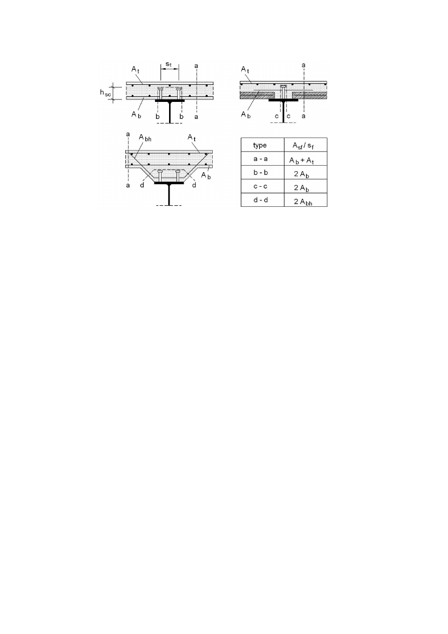
EN 1994-1-1: 2004 (E)
60
Figure 6.15 : Typical potential surfaces of shear failure
(3) The length of the shear surface c-c shown in Figure 6.15 should be taken as equal to 2h
sc
plus
the head diameter for a single row of stud shear connectors or staggered stud connectors, or as equal
to (2h
sc
+ s
t
) plus the head diameter for stud shear connectors arranged in pairs (surface b-b in
Figure 6.15), where h
sc
is the height of the studs and s
t
is the transverse spacing centre-to-centre of
the studs.
(4) The design longitudinal shear per unit length of beam on a shear surface should be determined
in accordance with 6.6.2 and be consistent with the design and spacing of the shear connectors.
Account may be taken of the variation of longitudinal shear across the width of the concrete flange.
(5) For each type of shear surface considered, the design longitudinal shear stress v
L,Ed
should be
determined from the design longitudinal shear per unit length of beam, taking account of the
number of shear planes and the length of the shear surface.
6.6.6.2 Design resistance to longitudinal shear
(1) The design shear strength of the concrete flange (shear planes a-a illustrated in Figure 6.15)
should be determined in accordance with EN 1992-1-1, 6.2.4.
(2) In the absence of a more accurate calculation the design shear strength of any surface of
potential shear failure in the flange or a haunch may be determined from EN 1992-1-1, 6.2.4(4). For
a shear surface passing around the shear connectors (e.g. shear surface b-b in Figure 6.15), the
dimension h
f
should be taken as the length of the shear surface.
(3) The effective transverse reinforcement per unit length, A
sf
/ s
f
in EN 1992-1-1, should be as
shown in Figure 6.15, in which A
b
, A
t
and A
bh
are areas of reinforcement per unit length of beam
anchored in accordance with EN 1992-1-1, 8.4 for longitudinal reinforcement.
(4) Where a combination of pre-cast elements and in-situ concrete is used, the resistance to
longitudinal shear should be determined in accordance with EN 1992-1-1, 6.2.5.
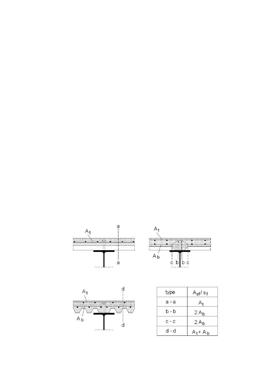
EN 1994-1-1:2004 (E)
61
6.6.6.3 Minimum transverse reinforcement
(1) The minimum area of reinforcement should be determined in accordance with EN 1992-1-1,
9.2.2(5) using definitions appropriate to transverse reinforcement.
6.6.6.4 Longitudinal shear and transverse reinforcement in beams for buildings
(1) Where profiled steel sheeting is used and the shear surface passes through the depth of the slab
(e.g. shear surface a-a in Figure 6.16), the dimension h
f
should be taken as the thickness of the
concrete above the sheeting.
(2) Where profiled steel sheeting is used transverse to the beam and the design resistances of the
studs are determined using the appropriate reduction factor k
t
as given in 6.6.4.2, it is not necessary
to consider shear surfaces of type b-b in Figure 6.16.
(3) Unless verified by tests, for surfaces of type c-c in Figure 6.16 the depth of the sheeting should
not be included in h
f
.
(4) Where profiled steel sheeting with mechanical or frictional interlock and with ribs transverse to
the beam is continuous across the top flange of the steel beam, its contribution to the transverse
reinforcement for a shear surface of type a-a may be allowed for by replacing expression (6.21) in
EN 1992-1-1, 6.2.4(4) by:
(A
sf
f
yd
/ s
f
) + A
pe
f
yp,d
> v
Ed
h
f
/ cot
θ
(6.25)
where:
A
pe
is the effective cross-sectional area of the profiled steel sheeting per unit length of the
beam, see 9.7.2(3); for sheeting with holes, the net area should be used;
f
yp,d
is its design yield strength.
Figure 6.16 : Typical potential surfaces of shear failure where profiled
steel sheeting is used
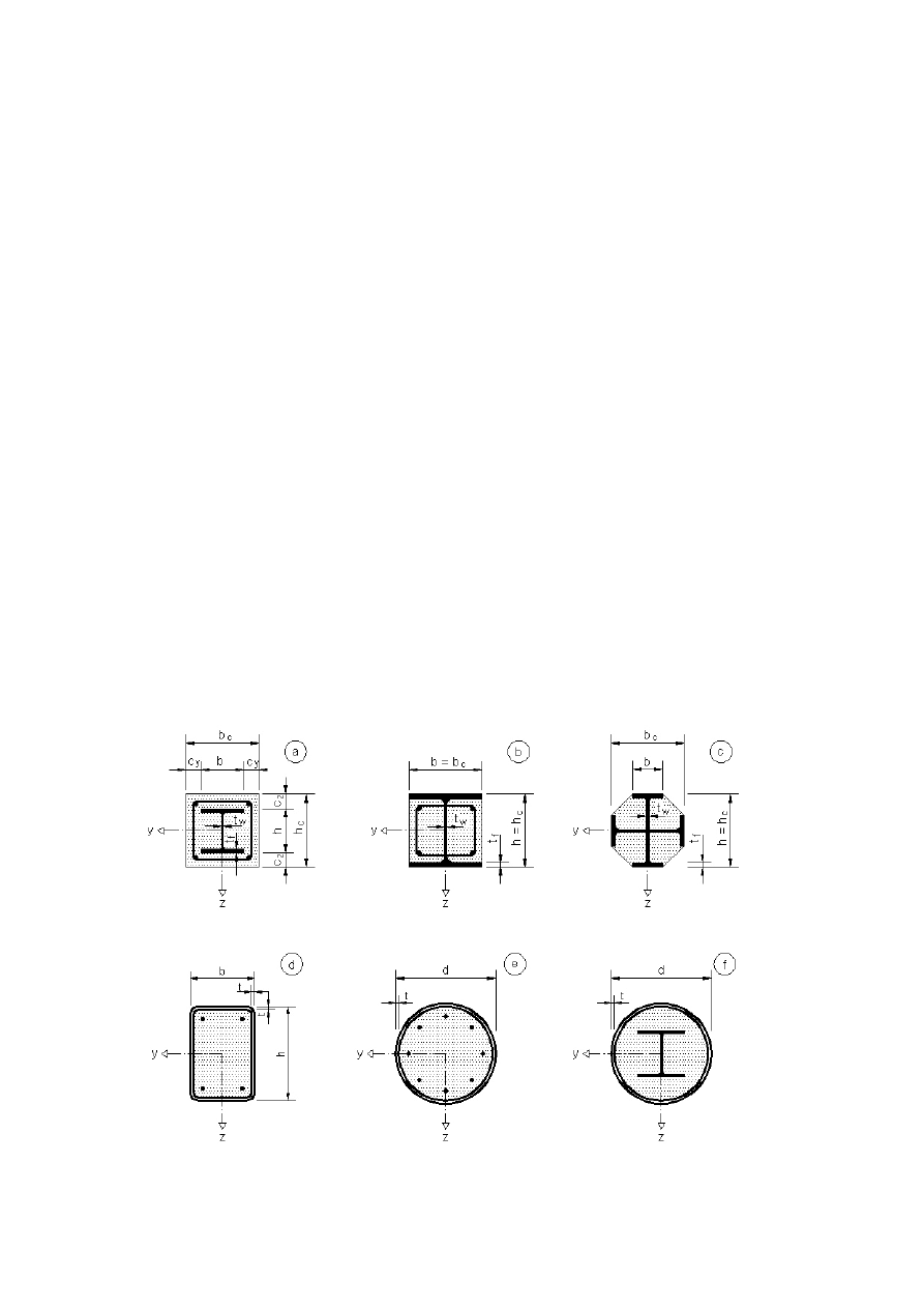
EN 1994-1-1: 2004 (E)
62
(5) Where the profiled steel sheeting with ribs transverse to the beam is discontinuous across the top
flange of the steel beam, and stud shear connectors are welded to the steel beam directly through the
profiled steel sheets, the term A
p
f
yp,d
in expression (6.25) should be replaced by:
P
pb,Rd
/ s but
≤ A
p
f
yp,d
(6.26)
where:
P
pb,Rd
is the design bearing resistance of a headed stud welded through the sheet according to
9.7.4;
s
is the longitudinal spacing centre-to-centre of the studs effective in anchoring the
sheeting.
(6) With profiled steel sheeting, the requirement for minimum reinforcement relates to the area of
concrete above the sheeting.
6.7 Composite columns and composite compression members
6.7.1 General
(1)P Clause 6.7 applies for the design of composite columns and composite compression members
with concrete encased sections, partially encased sections and concrete filled rectangular and
circular tubes, see Figure 6.17.
(2)P This clause applies to columns and compression members with steel grades S235 to S460 and
normal weight concrete of strength classes C20/25 to C50/60.
(3) This clause applies to isolated columns and columns and composite compression members in
framed structures where the other structural members are either composite or steel members.
Figure 6.17 : Typical cross-sections of composite columns and notation
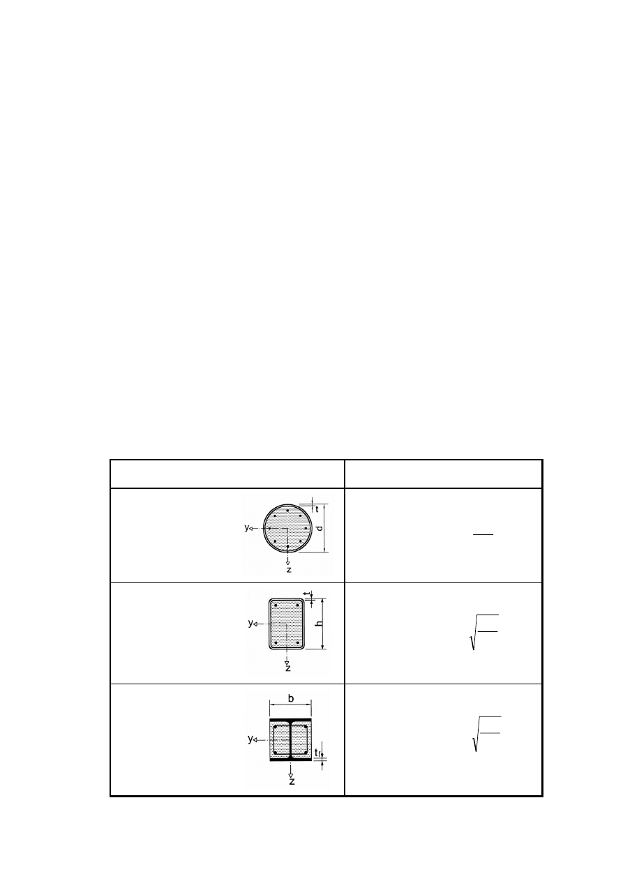
EN 1994-1-1:2004 (E)
63
(4) The steel contribution ratio
δ
should fulfil the following condition:
0.2
≤ δ ≤ 0.9
(6.27)
where
δ
is defined in 6.7.3.3(1).
(5) Composite columns or compression members of any cross-section should be checked for:
–
resistance of the member in accordance with 6.7.2 or 6.7.3;
–
resistance to local buckling in accordance with (8) and (9) below;
–
introduction of loads in accordance with 6.7.4.2 and
–
resistance to shear between steel and concrete elements in accordance with 6.7.4.3.
(6) Two methods of design are given:
–
a general method in 6.7.2 whose scope includes members with non-symmetrical or non-
uniform cross-sections over the column length and
–
a simplified method in 6.7.3 for members of doubly symmetrical and uniform cross
section over the member length.
(7) For composite compression members subjected to bending moments and normal forces resulting
from independent actions, the partial factor
γ
F
for those internal forces that lead to an increase of
resistance should be reduced by 20%.
Table 6.3 : Maximum values (d/t), (h/t) and (b/t
f
) with f
y
in N/mm
2
Cross-section
max (d/t), max (h/t) and max (b/t)
Circular hollow
steel sections
y
235
90
)
(
max
f
d/t
=
Rectangular hollow
steel sections
y
f
h/t
235
52
)
(
max
=
Partially encased
I-sections
y
f
b/t
235
44
)
(
max
f
=

EN 1994-1-1: 2004 (E)
64
(8)P The influence of local buckling of the steel section on the resistance shall be considered in
design.
(9) The effects of local buckling may be neglected for a steel section fully encased in accordance
with 6.7.5.1(2), and for other types of cross-section provided the maximum values of Table 6.3 are
not exceeded.
6.7.2 General method of design
(1)P Design for structural stability shall take account of second-order effects including residual
stresses, geometrical imperfections, local instability, cracking of concrete, creep and shrinkage of
concrete and yielding of structural steel and of reinforcement. The design shall ensure that
instability does not occur for the most unfavourable combination of actions at the ultimate limit
state and that the resistance of individual cross-sections subjected to bending, longitudinal force and
shear is not exceeded.
(2)P Second-order effects shall be considered in any direction in which failure might occur, if they
affect the structural stability significantly.
(3)P Internal forces shall be determined by elasto-plastic analysis.
(4) Plane sections may be assumed to remain plane. Full composite action up to failure may be
assumed between the steel and concrete components of the member.
(5)P The tensile strength of concrete shall be neglected. The influence of tension stiffening of
concrete between cracks on the flexural stiffness may be taken into account.
(6)P Shrinkage and creep effects shall be considered if they are likely to reduce the structural
stability significantly.
(7) For simplification, creep and shrinkage effects may be ignored if the increase in the first-order
bending moments due to creep deformations and longitudinal force resulting from permanent loads
is not greater than 10%.
(8) The following stress-strain relationships should be used in the non-linear analysis :
–
for concrete in compression as given in EN 1992-1-1, 3.1.5;
–
for reinforcing steel as given in EN 1992-1-1, 3.2.7;
–
for structural steel as given in EN 1993-1-1, 5.4.3(4).
(9) For simplification, instead of the effect of residual stresses and geometrical imperfections,
equivalent initial bow imperfections (member imperfections) may be used in accordance with
Table 6.5.
6.7.3 Simplified method of design
6.7.3.1 General and scope
(1) The scope of this simplified method is limited to members of doubly symmetrical and uniform
cross-section over the member length with rolled, cold-formed or welded steel sections. The
simplified method is not applicable if the structural steel component consists of two or more
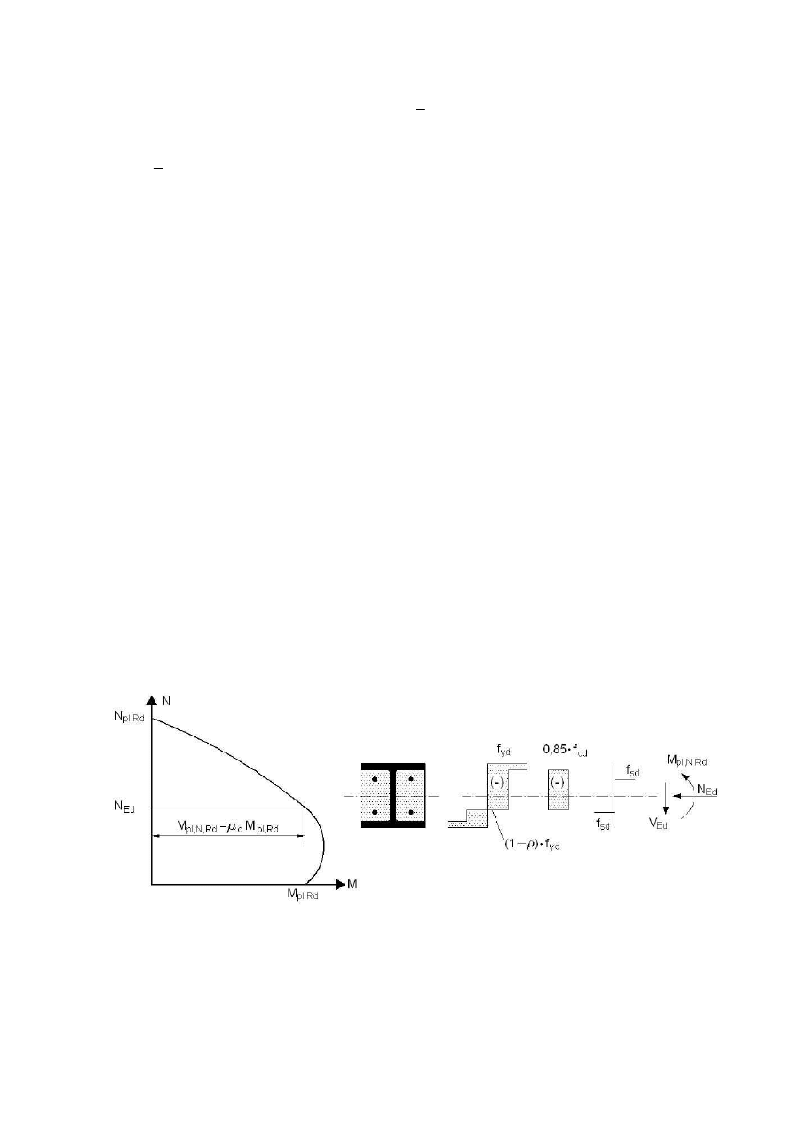
EN 1994-1-1:2004 (E)
65
unconnected sections. The relative slenderness
λ
defined in 6.7.3.3 should fulfil the following
condition:
0
.
2
≤
λ
(6.28)
(2) For a fully encased steel section, see Figure 6.17a, limits to the maximum thickness of concrete
cover that may be used in calculation are:
max c
z
= 0.3h max c
y
= 0.4 b
(6.29)
(3) The longitudinal reinforcement that may be used in calculation should not exceed 6% of the
concrete area.
(4) The ratio of the depth to the width of the composite cross-section should be within the limits 0.2
and 5.0.
6.7.3.2 Resistance of cross sections
(1) The plastic resistance to compression N
pl,Rd
of a composite cross-section should be calculated by
adding the plastic resistances of its components:
sd
s
cd
c
yd
a
Rd
pl,
85
.
0
f
A
f
A
f
A
N
+
+
=
(6.30)
Expression (6.30) applies for concrete encased and partially concrete encased steel sections. For
concrete filled sections the coefficient 0.85 may be replaced by 1.0.
(2) The resistance of a cross-section to combined compression and bending and the corresponding
interaction curve may be calculated assuming rectangular stress blocks as shown in Figure 6.18,
taking account of the design shear force V
Ed
in accordance with (3). The tensile strength of the
concrete should be neglected.
Figure 6.18 : Interaction curve for combined compression and uniaxial bending
(3) The influence of transverse shear forces on the resistance to bending and normal force should be
considered when determining the interaction curve, if the shear force V
a,Ed
on the steel section
exceeds 50% of the design shear resistance V
pl,a,Rd
of the steel section, see 6.2.2.2.
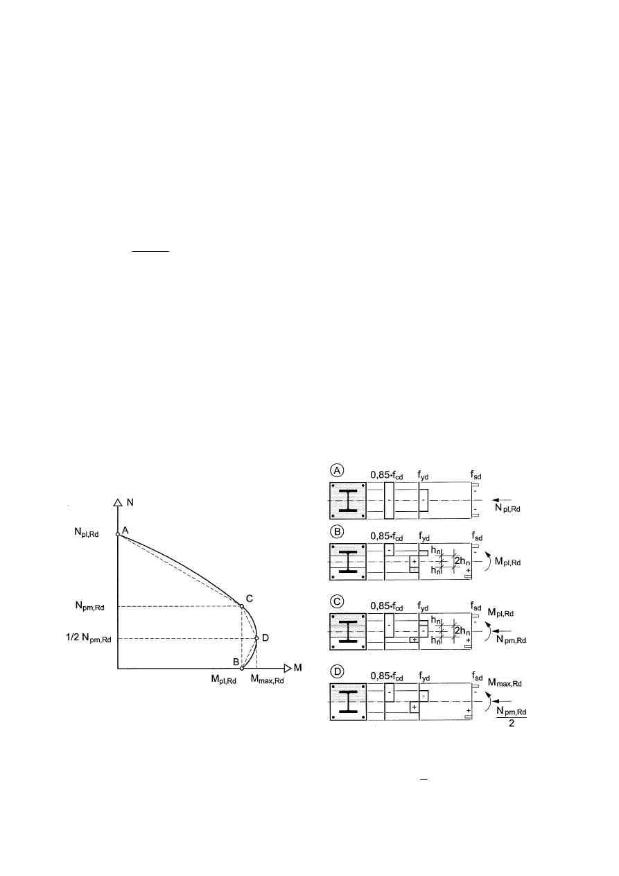
EN 1994-1-1: 2004 (E)
66
Where V
a,Ed
> 0,5V
pl,a,Rd
, the influence of the transverse shear on the resistance in combined
bending and compression should be taken into account by a reduced design steel strength (1 -
ρ
) f
yd
in the shear area A
v
in accordance with 6.2.2.4(2) and Figure 6.18.
The shear force V
a,Ed
should not exceed the resistance to shear of the steel section determined
according to 6.2.2. The resistance to shear V
c,Ed
of the reinforced concrete part should be verified in
accordance with EN 1992-1-1, 6.2.
(4) Unless a more accurate analysis is used, V
Ed
may be distributed into V
a,Ed
acting on the structural
steel and V
c,Ed
acting on the reinforced concrete section by :
Rd
pl,
Rd
a,
pl,
Ed
Ed
a,
M
M
V
V
=
(6.31)
Ed
a,
Ed
Ed
c,
V
V
V
−
=
(6.32)
where:
M
pl,a,Rd
is the plastic resistance moment of the steel section and
M
pl,Rd
is the plastic resistance moment of the composite section.
For simplification V
Ed
may be assumed to act on the structural steel section alone.
(5) As a simplification, the interaction curve may be replaced by a polygonal diagram (the dashed
line in Figure 6.19). Figure 6.19 shows as an example the plastic stress distribution of a fully
encased cross section for the points A to D. N
pm,Rd
should be taken as 0.85 f
cd
A
c
for concrete
encased and partially concrete encased sections, see Figures 6.17a – c, and as f
cd
A
c
for concrete
filled sections, see Figures 6.17d - f.
Figure 6.19 : Simplified interaction curve and corresponding stress distributions
(6) For concrete filled tubes of circular cross-section, account may be taken of increase in strength
of concrete caused by confinement provided that the relative slenderness
λ
defined in 6.7.3.3 does
not exceed 0.5 and e/d
< 0,1, where e is the eccentricity of loading given by M
Ed
/ N
Ed
and d is the

EN 1994-1-1:2004 (E)
67
external diameter of the column. The plastic resistance to compression may then be calculated from
the following expression:
sd
s
ck
y
c
cd
c
yd
a
a
Rd
pl,
1
f
A
f
f
d
t
f
A
f
A
N
+
+
+
=
η
η
(6.33)
where:
t
is the wall thickness of the steel tube.
For members with e = 0 the values
η
a
=
η
ao
and
η
c
=
η
co
are given by the following expressions:
η
ao
= 0.25 (3 + 2
λ
) (but
≤ 1,0)
(6.34)
η
co
=
4.9 – 18.5
λ
+ 17
λ
2
(but
≥ 0)
(6.35)
For members in combined compression and bending with 0 < e/d
≤ 0,1, the values η
a
and
η
c
should
be determined from (6.36) and (6.37), where
η
ao
and
η
co
are given by (6.34) and (6.35):
η
a
=
η
ao
+ (1 –
η
ao
) (10 e/d)
(6.36)
η
c
=
η
co
(1 – 10 e/d)
(6.37)
For e/d > 0.1,
η
a
= 1,0 and
η
c
= 0.
6.7.3.3 Effective flexural stiffness, steel contribution ratio and relative slenderness
(1) The steel contribution ratio
δ
is defined as:
Rd
pl,
yd
a
N
f
A
=
δ
(6.38)
where:
N
pl,Rd
is the plastic resistance to compression defined in 6.7.3.2(1).
(2) The relative slenderness
λ
for the plane of bending being considered is given by:
cr
Rk
pl,
N
N
=
λ
(6.39)
where:
N
pl,Rk
is the characteristic value of the plastic resistance to compression given by (6.30) if,
instead of the design strengths, the characteristic values are used;
N
cr
is the elastic critical normal force for the relevant buckling mode, calculated with the
effective flexural stiffness (EI)
eff
determined in accordance with (3) and (4).
(3) For the determination of the relative slenderness
λ
and the elastic critical force N
cr
, the
characteristic value of the effective flexural stiffness (EI)
eff
of a cross section of a composite column
should be calculated from:
c
cm
e
s
s
a
a
eff
)
(
I
E
K
I
E
I
E
I
E
+
+
=
(6.40)

EN 1994-1-1: 2004 (E)
68
where:
K
e
is a correction factor that should be taken as 0.6.
I
a
, I
c
, and I
s
are the second moments of area of the structural steel section, the un-cracked
concrete section and the reinforcement for the bending plane being considered.
(4) Account should be taken to the influence of long-term effects on the effective elastic flexural
stiffness. The modulus of elasticity of concrete E
cm
should be reduced to the value E
c,eff
in
accordance with the following expression:
t
Ed
Ed
G,
cm
eff
c,
)
/
(
1
1
ϕ
N
N
E
E
+
=
(6.41)
where:
ϕ
t
is the creep coefficient according to 5.4.2.2(2);
N
Ed
is the total design normal force;
N
G,Ed
is the part of this normal force that is permanent.
6.7.3.4 Methods of analysis and member imperfections
(1) For member verification, analysis should be based on second-order linear elastic analysis.
(2) For the determination of the internal forces the design value of effective flexural stiffness
(EI)
eff,II
should be determined from the following expression:
)
(
)
(
c
cm
II
e,
s
s
a
a
o
II
eff,
I
E
K
I
E
I
E
K
I
E
+
+
=
(6.42)
where:
K
e,II
is a correction factor which should be taken as 0.5;
K
o
is a calibration factor which should be taken as 0.9.
Long-term effects should be taken into account in accordance with 6.7.3.3 (4).
(3) Second-order effects need not to be considered where 5.2.1(3) applies and the elastic critical
load is determined with the flexural stiffness (EI)
eff,II
in accordance with (2).
(4) The influence of geometrical and structural imperfections may be taken into account by
equivalent geometrical imperfections. Equivalent member imperfections for composite columns are
given in Table 6.5, where L is the column length.
(5) Within the column length, second-order effects may be allowed for by multiplying the greatest
first-order design bending moment M
Ed
by a factor k given by:
eff
cr,
Ed
/
1
N
N
k
−
=
β
,
≥ 1.0
(6.43)
where:
N
cr,eff
is the critical normal force for the relevant axis and corresponding to the effective
flexural stiffness given in 6.7.3.4(2), with the effective length taken as the column
length;
β
is an equivalent moment factor given in Table 6.4.
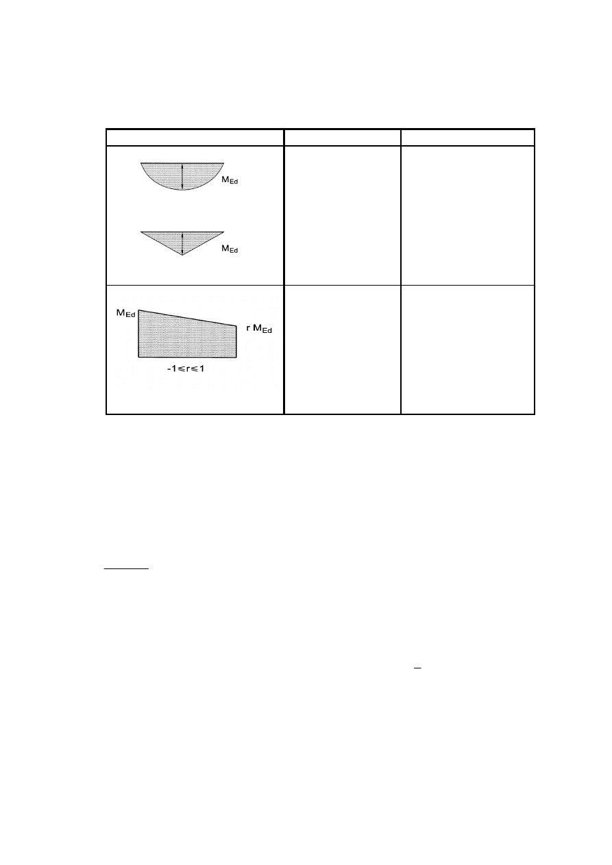
EN 1994-1-1:2004 (E)
69
Table 6.4 Factors
β
for the determination of moments to second order theory
Moment distribution
Moment factors
β
Comment
First-order bending
moments from
member
imperfection or
lateral load:
β
= 1.0
M
Ed
is the maximum
bending moment within
the column length
ignoring second-order
effects
End moments:
β
= 0.66 + 0,44r
but
β
≥ 0.44
M
Ed
and r M
Ed
are the
end moments from first-
order or second-order
global analysis
6.7.3.5 Resistance of members in axial compression
(1) Members may be verified using second order analysis according to 6.7.3.6 taking into account
member imperfections.
(2) For simplification for members in axial compression, the design value of the normal force N
Ed
should satisfy:
0
.
1
Rd
pl,
Ed
≤
χ N
N
(6.44)
where:
N
pl,Rd
is the plastic resistance of the composite section according to 6.7.3.2(1), but with
f
yd
determined using the partial factor
γ
M1
given by EN 1993-1-1, 6.1(1);
χ
is the reduction factor for the relevant buckling mode given in EN 1993-1-1,
6.3.1.2 in terms of the relevant relative slenderness
λ
.
The relevant buckling curves for cross-sections of composite columns are given in Table 6.5, where
ρ
s
is the reinforcement ratio A
s
/ A
c
.
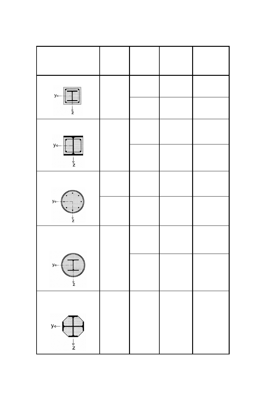
EN 1994-1-1: 2004 (E)
70
Table 6.5 : Buckling curves and member imperfections for composite columns
Cross-section
Limits
Axis of
buckling
Buckling
curve
Member
imperfection
y-y
b
L
/200
concrete encased section
z-z
c
L
/150
y-y
b
L
/200
partially concrete encased
section
z-z
c
L
/150
ρ
s
≤3%
any
a
L
/300
circular and rectangular
hollow steel section
3%<
ρ
s
≤6%
any
b
L
/200
y-y
b
L
/200
circular hollow steel
sections
with additional I-section
z-z
b
L
/200
partially concrete encased
section with crossed I-
sections
any
b
L
/200
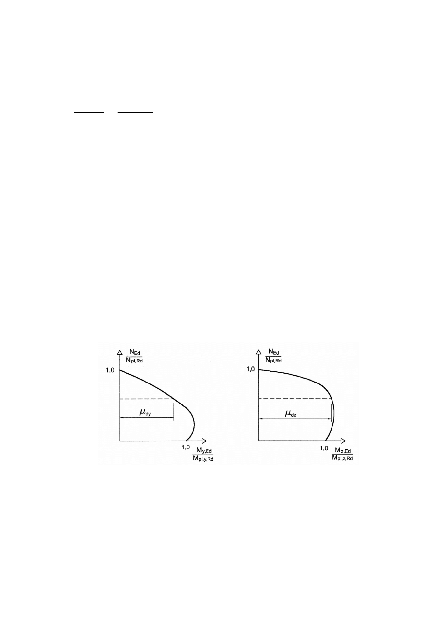
EN 1994-1-1:2004 (E)
71
6.7.3.6 Resistance of members in combined compression and uniaxial bending
(1) The following expression based on the interaction curve determined according to 6.7.3.2 (2) -
(5) should be satisfied:
M
Rd
pl,
d
Ed
Rd
N,
pl,
Ed
α
µ
≤
=
M
M
M
M
(6.45)
where:
M
Ed
is the greatest of the end moments and the maximum bending moment within the
column length, calculated according to 6.7.3.4, including imperfections and second
order effects if necessary;
M
pl,N,Rd
is the plastic bending resistance taking into account the normal force N
Ed
, given by
µ
d
M
pl,Rd
, see Figure 6.18;
M
pl,Rd
is the plastic bending resistance, given by point B in Figure 6.19.
For steel grades between S235 and S355 inclusive, the coefficient
α
M
should be taken as 0.9 and for
steel grades S420 and S460 as 0.8.
(2) The value
µ
d
=
µ
dy
or
µ
dz
, see Figure 6.20, refers to the design plastic resistance moment M
pl,Rd
for the plane of bending being considered. Values
µ
d
greater than 1.0 should only be used where the
bending moment M
Ed
depends directly on the action of the normal force N
Ed
, for example where the
moment M
Ed
results from an eccentricity of the normal force N
Ed
. Otherwise an additional
verification is necessary in accordance with clause 6.7.1 (7).
Figure 6.20 : Design for compression and biaxial bending
6.7.3.7 Combined compression and biaxial bending
(1) For composite columns and compression members with biaxial bending the values
µ
dy
and
µ
dz
in
Figure 6.20 may be calculated according to 6.7.3.6 separately for each axis. Imperfections should be
considered only in the plane in which failure is expected to occur. If it is not evident which plane is
the more critical, checks should be made for both planes.

EN 1994-1-1: 2004 (E)
72
(2) For combined compression and biaxial bending the following conditions should be satisfied for
the stability check within the column length and for the check at the end:
y
M,
Rd
y,
pl,
dy
Ed
y,
α
µ
≤
M
M
z
M,
Rd
z,
pl,
dz
Ed
z,
α
µ
≤
M
M
(6.46)
0
.
1
Rd
z,
pl,
z
d
Ed
z,
Rd
y,
pl,
dy
Ed
y,
≤
µ
+
µ
M
M
M
M
(6.47)
where:
M
pl,y,Rd
and M
pl,z,Rd
are the plastic bending resistances of the relevant plane of bending;
M
y,Ed
and M
z,Ed
are the design bending moments including second-order effects and
imperfections according to 6.7.3.4;
µ
dy
and
µ
dz
are defined in 6.7.3.6;
α
M
=
α
M,y
and
α
M
=
α
M,z
are given in 6.7.3.6(1).
6.7.4 Shear connection and load introduction
6.7.4.1 General
(1)P Provision shall be made in regions of load introduction for internal forces and moments
applied from members connected to the ends and for loads applied within the length to be
distributed between the steel and concrete components, considering the shear resistance at the
interface between steel and concrete. A clearly defined load path shall be provided that does not
involve an amount of slip at this interface that would invalidate the assumptions made in design.
(2)P Where composite columns and compression members are subjected to significant transverse
shear, as for example by local transverse loads and by end moments, provision shall be made for the
transfer of the corresponding longitudinal shear stress at the interface between steel and concrete.
(3) For axially loaded columns and compression members, longitudinal shear outside the areas of
load introduction need not be considered.
6.7.4.2 Load introduction
(1) Shear connectors should be provided in the load introduction area and in areas with change of
cross section, if the design shear strength
τ
Rd
, see 6.7.4.3, is exceeded at the interface between steel
and concrete. The shear forces should be determined from the change of sectional forces of the steel
or reinforced concrete section within the introduction length. If the loads are introduced into the
concrete cross section only, the values resulting from an elastic analysis considering creep and
shrinkage should be taken into account. Otherwise, the forces at the interface should be determined
by elastic theory or plastic theory, to determine the more severe case.
(2) In absence of a more accurate method, the introduction length should not exceed 2d or L/3,
where d is the minimum transverse dimension of the column and L is the column length.
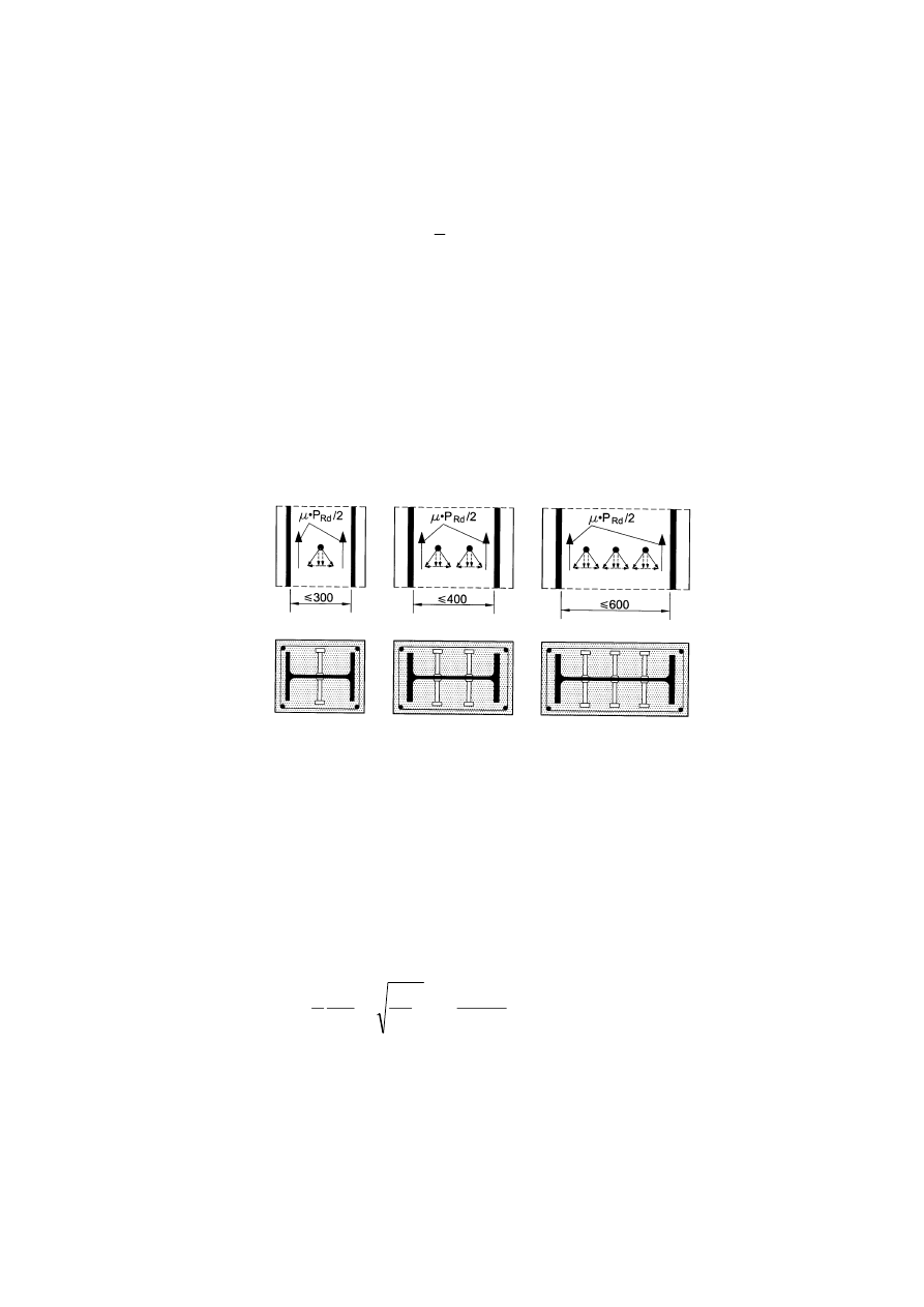
EN 1994-1-1:2004 (E)
73
(3) For composite columns and compression members no shear connection need be provided for
load introduction by endplates if the full interface between the concrete section and endplate is
permanently in compression, taking account of creep and shrinkage. Otherwise the load
introduction should be verified according to (5). For concrete filled tubes of circular cross-section
the effect caused by the confinement may be taken into account if the conditions given in 6.7.3.2(6)
are satisfied using the values
η
a
and
η
c
for
λ
equal to zero.
(4) Where stud connectors are attached to the web of a fully or partially concrete encased steel
I-section or a similar section, account may be taken of the frictional forces that develop from the
prevention of lateral expansion of the concrete by the adjacent steel flanges. This resistance may be
added to the calculated resistance of the shear connectors. The additional resistance may be
assumed to be
2
/
Rd
P
µ
on each flange and each horizontal row of studs, as shown in Figure 6.21,
where
µ
is the relevant coefficient of friction that may be assumed. For steel sections without
painting,
µ
may be taken as 0.5. P
Rd
is the resistance of a single stud in accordance with 6.6.3.1. In
absence of better information from tests, the clear distance between the flanges should not exceed
the values given in Figure 6.21.
Figure 6.21 : Additional frictional forces in composite columns by use of headed studs
(5) If the cross-section is partially loaded (as, for example, Figure 6.22A), the loads may be
distributed with a ratio of 1:2,5 over the thickness t
e
of the end plate. The concrete stresses should
then be limited in the area of the effective load introduction, for concrete filled hollow sections in
accordance with (6) and for all other types of cross-sections in accordance with EN 1992-1-1, 6.7.
(6) If the concrete in a filled circular hollow section or a square hollow section is only partially
loaded, for example by gusset plates through the profile or by stiffeners as shown in Figure 6.22,
the local design strength of concrete,
σ
c,Rd
under the gusset plate or stiffener resulting from the
sectional forces of the concrete section should be determined by:
yd
1
cd
c
1
c
ck
y
cL
cd
Rd
c,
,
1
f
A
f
A
A
A
f
f
a
t
f
≤
≤
+
=
η
σ
(6.48)
where:
t
is the wall thickness of the steel tube;
a
is the diameter of the tube or the width of the square section;
A
c
is the cross sectional area of the concrete section of the column;
A
1
is the loaded area under the gusset plate, see Figure 6.22;
η
cL
= 4.9 for circular steel tubes and 3.5 for square sections.
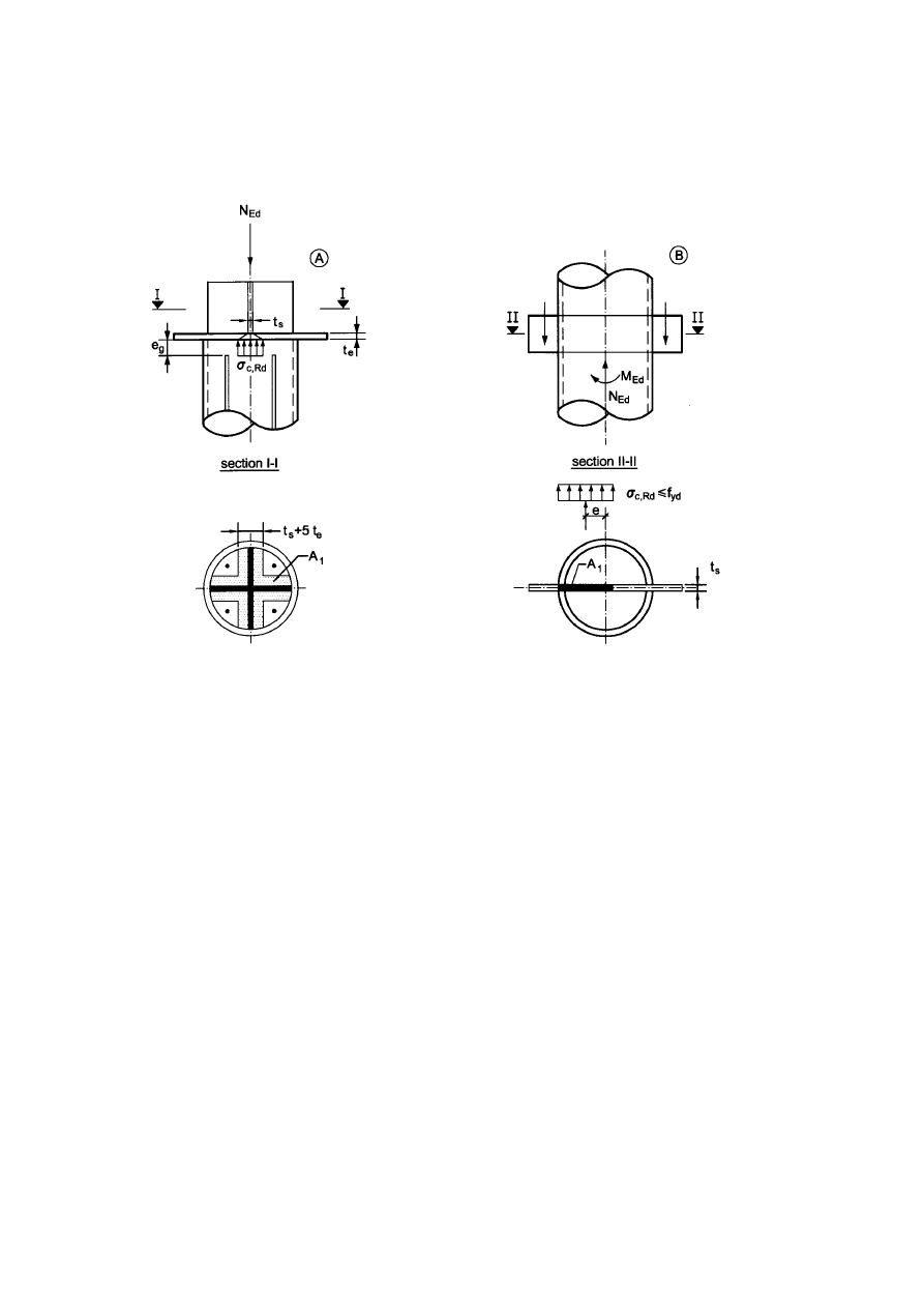
EN 1994-1-1: 2004 (E)
74
The ratio A
c
/A
1
should not exceed the value 20. Welds between the gusset plate and the steel hollow
sections should be designed according to EN1993-1-8, Section 4.
Figure 6.22 : Partially loaded circular concrete filled hollow section
(7) For concrete filled circular hollow sections, longitudinal reinforcement may be taken into
account for the resistance of the column, even where the reinforcement is not welded to the end
plates or in direct contact with the endplates, provided that:
– verification
for
fatigue is not required,
– the gap e
g
between the reinforcement and the end plate does not exceed 30 mm, see
Figure 6.22A.
(8) Transverse reinforcement should be in accordance with EN 1992-1-1, 9.5.3. In case of partially
encased steel sections, concrete should be held in place by transverse reinforcement arranged in
accordance with Figure 6.10.
(9) In the case of load introduction through only the steel section or the concrete section, for fully
encased steel sections the transverse reinforcement should be designed for the longitudinal shear
that results from the transmission of normal force (N
c1
in Figure 6.23) from the parts of concrete
directly connected by shear connectors into the parts of the concrete without direct shear connection
(see Figure 6.23, section A-A; the hatched area outside the flanges of Figure 6.23 should be
considered as not directly connected). The design and arrangement of transverse reinforcement
should be based on a truss model assuming an angle of 45° between concrete compression struts
and the member axis.
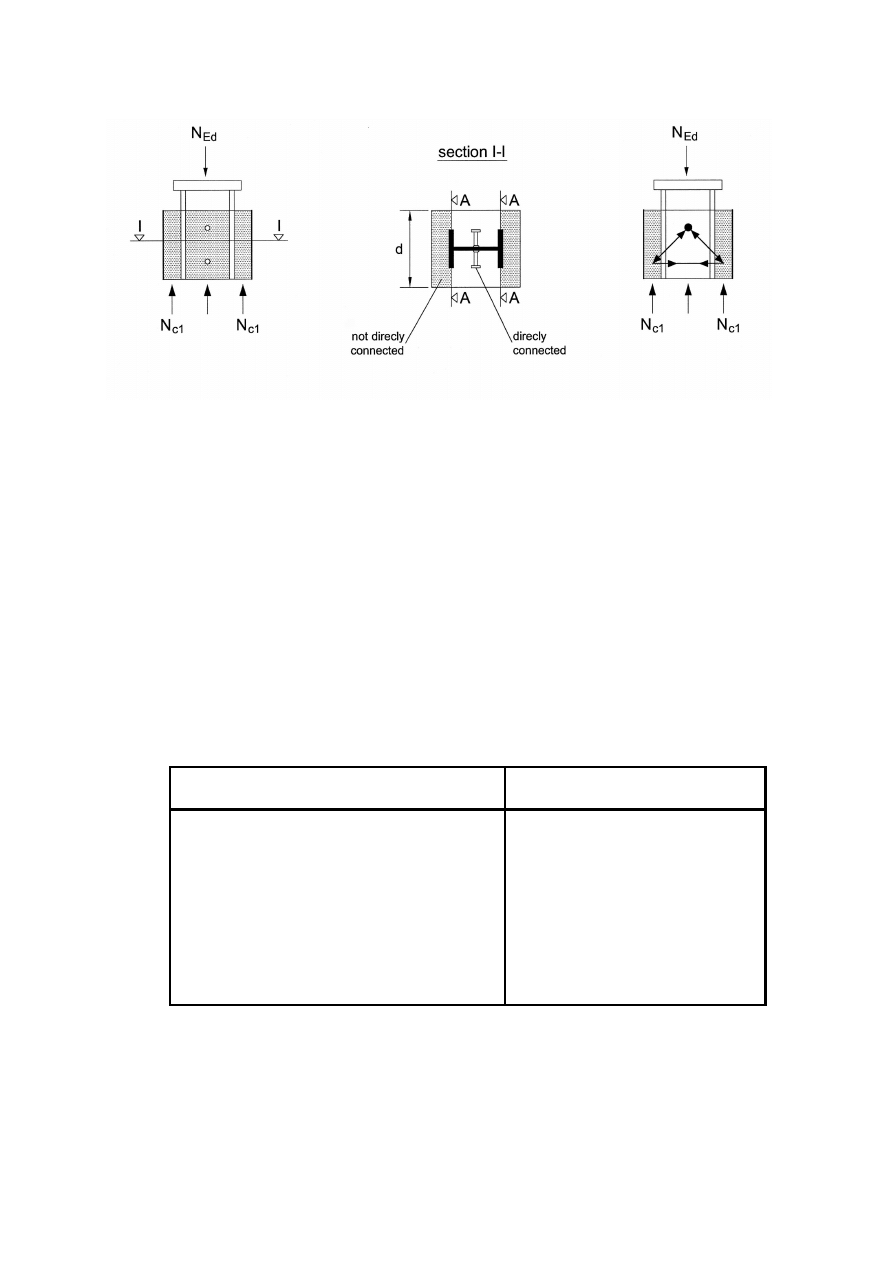
EN 1994-1-1:2004 (E)
75
Figure 6.23 : Directly and not directly connected concrete areas for the design of transverse
reinforcement
6.7.4.3 Longitudinal shear outside the areas of load introduction
(1) Outside the area of load introduction, longitudinal shear at the interface between concrete and
steel should be verified where it is caused by transverse loads and /or end moments. Shear
connectors should be provided, based on the distribution of the design value of longitudinal shear,
where this exceeds the design shear strength
τ
Rd
.
(2) In absence of a more accurate method, elastic analysis, considering long term effects and
cracking of concrete, may be used to determine the longitudinal shear at the interface.
(3) Provided that the surface of the steel section in contact with the concrete is unpainted and free
from oil, grease and loose scale or rust, the values given in Table 6.6 may be assumed for
τ
Rd
.
Table 6.6 : Design shear strength
τ
Rd
Type of cross section
τ
Rd
(N/mm
2
)
Completely concrete encased steel sections
0.30
Concrete filled circular hollow sections
0.55
Concrete filled rectangular hollow sections
0.40
Flanges of partially encased sections
0.20
Webs of partially encased sections
0.00
(4) The value of
τ
Rd
given in Table 6.6 for completely concrete encased steel sections applies to
sections with a minimum concrete cover of 40mm and transverse and longitudinal reinforcement in
accordance with 6.7.5.2. For greater concrete cover and adequate reinforcement, higher values of
τ
Rd
may be used. Unless verified by tests, for completely encased sections the increased value
β
c
τ
Rd
may be used, with
β
c
given by:

EN 1994-1-1: 2004 (E)
76
5
.
2
1
02
,
0
1
z
min
z,
z
c
≤
−
+
=
β
c
c
c
(6.49)
where:
c
z
is the nominal value of concrete cover in mm, see Figure 6.17a;
min
z,
c
= 40 mm is the minimum concrete cover.
(5) Unless otherwise verified, for partially encased I-sections with transverse shear due to bending
about the weak axis due to lateral loading or end moments, shear connectors should always be
provided. If the resistance to transverse shear is not be taken as only the resistance of the structural
steel, then the required transverse reinforcement for the shear force V
c,Ed
according to 6.7.3.2(4)
should be welded to the web of the steel section or should pass through the web of the steel section.
6.7.5 Detailing Provisions
6.7.5.1 Concrete cover of steel profiles and reinforcement
(1)P For fully encased steel sections at least a minimum cover of reinforced concrete shall be
provided to ensure the safe transmission of bond forces, the protection of the steel against corrosion
and spalling of concrete.
(2) The concrete cover to a flange of a fully encased steel section should be not less than 40mm, nor
less than one-sixth of the breadth b of the flange.
(3) The cover to reinforcement should be in accordance with EN 1992-1-1, Section 4.
6.7.5.2 Longitudinal and transverse reinforcement
(1) The longitudinal reinforcement in concrete-encased columns which is allowed for in the
resistance of the cross-section should be not less than 0,3% of the cross-section of the concrete. In
concrete filled hollow sections normally no longitudinal reinforcement is necessary, if design for
fire resistance is not required.
(2) The transverse and longitudinal reinforcement in fully or partially concrete encased columns
should be designed and detailed in accordance with EN 1992-1-1, 9.5.
(3) The clear distance between longitudinal reinforcing bars and the structural steel section may be
smaller than required by (2), even zero. In this case, for bond the effective perimeter c of the
reinforcing bar should be taken as half or one quarter of its perimeter, as shown in Figure 6.24 at (a)
and (b) respectively.
(4) For fully or partially encased members, where environmental conditions are class X0 according
to EN 1992-1-1, Table 4.1, and longitudinal reinforcement is neglected in design, a minimum
longitudinal reinforcement of diameter 8 mm and 250 mm spacing and a transverse reinforcement
of diameter 6 mm and 200 mm spacing should be provided. Alternatively welded mesh
reinforcement of diameter 4 mm may be used.
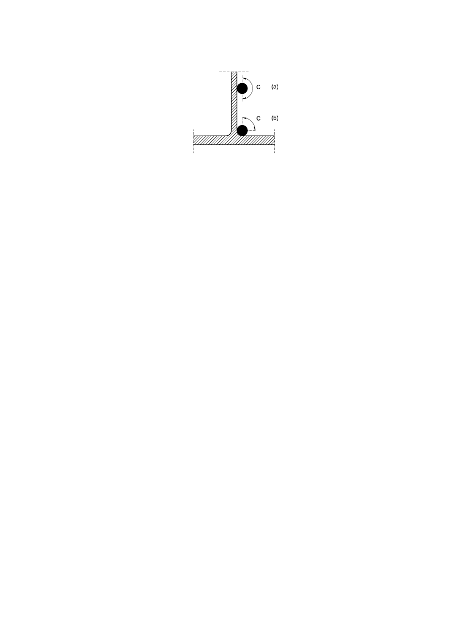
EN 1994-1-1:2004 (E)
77
Figure 6.24 : Effective perimeter c of a reinforcing bar
6.8 Fatigue
6.8.1 General
(1)P The resistance of composite structures to fatigue shall be verified where the structures are
subjected to repeated fluctuations of stresses.
(2)P Design for the limit state of fatigue shall ensure, with an acceptable level of probability, that
during its entire design life, the structure is unlikely to fail by fatigue or to require repair of damage
caused by fatigue.
(3) For headed stud shear connectors in buildings, under the characteristic combination of actions
the maximum longitudinal shear force per connector should not exceed 0,75P
Rd
, where P
Rd
is
determined according to 6.6.3.1.
(4) In buildings no fatigue assessment for structural steel, reinforcement, concrete and shear
connection is required where, for structural steel, EN 1993-1-1, 4(4) applies and, for concrete,
EN 1992-1-1, 6.8.1, does not apply.
6.8.2 Partial factors for fatigue assessment for buildings
(1) Partial factors
γ
Mf
for fatigue strength are given in EN 1993-1-9, 3 for steel elements and in
EN 1992-1-1, 2.4.2.4 for concrete and reinforcement. For headed studs in shear, a partial factor
γ
Mf,s
should be applied.
NOTE: The value for
γ
Mf,s
may be given in the National Annex. The recommended value for
γ
Mf,s
is 1,0.
(2) Partial factors for fatigue loading
γFf should be applied.
NOTE: Partial factors
γFf for different kinds of fatigue loading may be given in the National Annex.
6.8.3 Fatigue strength
(1) The fatigue strength for structural steel and for welds should be taken from EN 1993-1-9, 7.
(2) The fatigue strength of reinforcing steel and pre-stressing steel should be taken from
EN 1992-1-1. For concrete EN 1992-1-1, 6.8.5 applies.
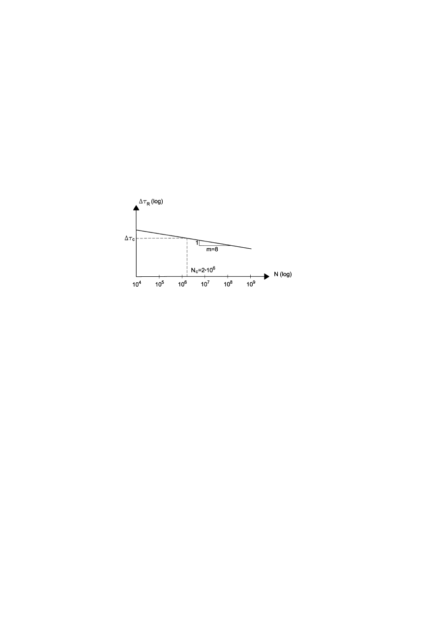
EN 1994-1-1: 2004 (E)
78
(3) The fatigue strength curve of an automatically welded headed stud in accordance with 6.6.3.1 is
shown in Fig. 6.25 and given for normal weight concrete by:
c
m
c
R
m
R
)
(
)
(
N
N
τ
∆
τ
∆
=
(6.50)
where:
∆τ
R
is the fatigue shear strength related to the cross-sectional area of the shank of the
stud, using the nominal diameter d of the shank;
∆τ
c
is the reference value at 2 million cycles with
∆τ
c
equal to 90 N/mm
2
;
m
is the slope of the fatigue strength curve with the value m = 8;
N
R
is the number of stress-range cycles.
Figure 6.25 : Fatigue strength curve for headed studs in solid slabs
(4) For studs in lightweight concrete with a density class according to EN 1992-1-1, 11, the fatigue
strength should be determined in accordance with (3) but with
∆τ
R
replaced by
η
E
∆τ
R
and
∆τ
c
replaced by
η
E
∆τ
c
, where
η
E
is given in EN 1992-1-1, 11.3.2.
6.8.4 Internal forces and fatigue loadings
(1) Internal forces and moments should be determined by elastic global analysis of the structure in
accordance with 5.4.1 and 5.4.2 and for the combination of actions given in EN 1992-1-1, 6.8.3.
(2) The maximum and minimum internal bending moments and/or internal forces resulting from the
load combination according to (1) are defined as M
Ed
,
max,f
and M
Ed,min,f
.
(3) For buildings fatigue loading should be obtained from the relevant Parts of EN 1991. Where no
fatigue loading is specified, EN 1993-1-9, Annex A.1 may be used. Dynamic response of the
structure or impact effects should be considered when appropriate.
6.8.5 Stresses
6.8.5.1 General
(1) The calculation of stresses should be based on 7.2.1.
(2)P For the determination of stresses in cracked regions the effect of tension stiffening of concrete
on the stresses in reinforcement shall be taken into account.
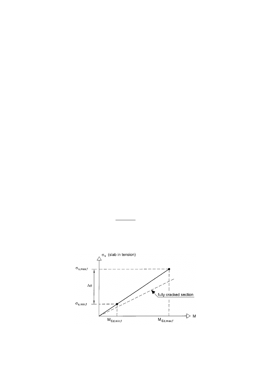
EN 1994-1-1:2004 (E)
79
(3) Unless verified by a more accurate method, the effect of tension stiffening on the stresses in
reinforcement may be taken into account according to 6.8.5.4.
(4) Unless a more accurate method is used, for the determination of stresses in structural steel the
effect of tension stiffening may be neglected.
6.8.5.2 Concrete
(1) For the determination of stresses in concrete elements EN 1992-1-1, 6.8 applies.
6.8.5.3 Structural steel
(1) Where the bending moments M
Ed,max,f
and M
Ed,min,f
cause tensile stresses in the concrete slab, the
stresses in structural steel for these bending moments may be determined based on the second
moment of area I
2
according to 1.5.2.12.
(2) Where M
Ed,min,f
and M
Ed,max,f
, or only M
Ed,min,f
, cause compression in the concrete slab, the
stresses in structural steel for these bending moments should be determined with the cross-section
properties of the un-cracked section.
6.8.5.4 Reinforcement
(1) Where the bending moment M
Ed,max,f
causes tensile stresses in the concrete slab and where no
more accurate method is used, the effects of tension stiffening of concrete on the stress
σ
s,max,f
in
reinforcement due to M
Ed,max,f
should be determined from the equations (7.4) to (7.6) in 7.4.3 (3). In
equation (7.5) in 7.4.3(3), a factor 0,2 should be used, in place of the factor 0,4.
(2) Where also the bending moment M
Ed,min,f
causes tensile stresses in the concrete slab, the stress
range ∆σ is given by Figure 6.26 and the stress σ
s,min,f
in the reinforcement due to M
Ed,min,f
can be
determined from:
f
max,
Ed,
f
min,
Ed,
f
max,
s,
f
min,
s,
M
M
σ
σ
=
(6.51)
(3) Where M
Ed
,
min,f
and M
Ed,max,f
or only M
Ed,min,f
cause compression in the concrete slab, the stresses
in reinforcement for these bending moments should be determined with the cross-section properties
of the un-cracked section.
Figure 6.26 : Determination of the stresses
σ
s,max,f
and
σ
s,min,f
in cracked regions

EN 1994-1-1: 2004 (E)
80
6.8.5.5 Shear Connection
(1)P The longitudinal shear per unit length shall be calculated by elastic analysis.
(2) In members where cracking of concrete occurs the effects of tension stiffening should be taken
into account by an appropriate model. For simplification, the longitudinal shear forces at the
interface between structural steel and concrete may be determined by using the properties of the
un-cracked section.
6.8.6 Stress ranges
6.8.6.1 Structural steel and reinforcement
(1) The stress ranges should be determined from the stresses determined in accordance with 6.8.5
(2) Where the verification for fatigue is based on damage equivalent stress ranges, in general a
range
∆σ
E
should be determined from:
f
min,
f
max,
E
σ
σ
φ
λ
σ
∆
−
=
(6.52)
where:
σ
max,f
and
σ
min,f
are the maximum and minimum stresses due to 6.8.4 and 6.8.5;
λ
is a damage equivalent factor;
φ
is a damage equivalent impact factor.
(3) Where a member is subjected to combined global and local effects the separate effects should be
considered. Unless a more precise method is used the equivalent constant amplitude stress due to
global effects and local effects should be combined using:
loc
E,
loc
loc
glob
E,
glob
glob
E
σ
∆
φ
λ
σ
∆
φ
λ
σ
∆
+
=
(6.53)
in which subscripts “glob” and “loc” refer to global and local effects, respectively.
(4) For buildings,
∆σ
E
for structural steel may taken as the stress range
∆σ
E,2
defined in
EN 1993-1-9, 1.3 and for reinforcement as the stress range
∆σ
s,equ
given by EN 1992-1-1, 6.8.5.
(5) For buildings the damage equivalent factor
λ
is defined in EN 1993-1-9, 6.2 and in the relevant
parts of EN 1993 for steel elements and for reinforcing steel in the relevant Parts of EN 1992.
(6) Where for buildings no value for
λ
is specified,
the damage equivalent factor should be
determined according to EN 1993-1-9, Annex A, using the slope of the relevant fatigue strength
curve.
6.8.6.2 Shear connection
(1) For verification of stud shear connectors based on nominal stress ranges the equivalent constant
range of shear stress
∆τ
E,2
for 2 million cycles is given by:
τ
∆
λ
τ
∆
v
E,2
=
(6.54)

EN 1994-1-1:2004 (E)
81
where:
λ
v
is the damage equivalent factor depending on the spectra and the slope m of the fatigue
strength curve;
∆τ
is the range of shear stress due to fatigue loading, related to the cross-sectional area of
the shank of the stud using the nominal diameter d of the shank.
(2) The equivalent constant amplitude shear stress range in welds of other types of shear connection
should be calculated in accordance with EN 1993-1-9, 6.
(3) Where for stud connectors in buildings no value for
λ
v
is specified
,
the damage equivalent factor
should be determined in accordance with EN 1993-1-9, Annex A, using the relevant slope of the
fatigue strength curve of the stud connector, given in 6.8.3.
6.8.7 Fatigue assessment based on nominal stress ranges
6.8.7.1 Structural steel, reinforcement and concrete
(1) The fatigue assessment for reinforcement should follow EN 1992-1-1, 6.8.5 or 6.8.6
(2) The verification for concrete in compression should follow EN 1992-1-1, 6.8.7.
(3) For buildings the fatigue assessment for structural steel should follow EN 1993-1-9, 8.
6.8.7.2 Shear connection
(1) For stud connectors welded to a steel flange that is always in compression under the relevant
combination of actions (see 6.8.4 (1)), the fatigue assessment should be made by checking the
criterion:
s
Mf,
c
E,2
Ff
/
γ
τ
∆
τ
∆
γ
≤
(6.55)
where:
∆τ
E,2
is defined in 6.8.6.2(1);
∆τ
c
is the reference value of fatigue strength at 2 million cycles determined in accordance
with 6.8.3.
(2) Where the maximum stress in the steel flange to which stud connectors are welded is tensile
under the relevant combination, the interaction at any cross-section between shear stress range
∆τ
E
in the weld of stud connectors and the normal stress range
∆σ
E
in the steel flange should be verified
using the following interaction expressions.
3
.
1
/
/
s
Mf,
c
E,2
Ff
Mf
c
E,2
Ff
≤
γ
τ
∆
τ
∆
γ
+
γ
σ
∆
σ
∆
γ
(6.56)
0
.
1
/
0
.
1
/
s
Mf,
c
E,2
Ff
Mf
c
E,2
Ff
≤
γ
τ
∆
τ
∆
γ
≤
γ
σ
∆
σ
∆
γ
(6.57)

EN 1994-1-1: 2004 (E)
82
where:
∆σ
E,2
is the stress range in the flange determined in accordance with 6.8.6.1;
∆σ
c
is the reference value of fatigue strength given in EN1993-1-9, 7, by applying
category 80,
and the stress ranges
∆τ
E,2
and
∆τ
c
are defined in (1).
Expression (6.56) should be checked for the maximum value of
∆σ
E,2
and the corresponding value
∆τ
E,2
, as well as for the combination of the maximum value of
∆τ
E,2
and the corresponding value of
∆σ
E,2
. Unless taking into account the effect of tension stiffening of concrete by more accurate
methods, the interaction criterion should be verified with the corresponding stress ranges
determined with both cracked and un-cracked cross-sectional properties.
Section 7 Serviceability limit states
7.1 General
(1)P A structure with composite members shall be designed and constructed such that all relevant
serviceability limit states are satisfied according to the Principles of 3.4 of EN 1990.
(2) The verification of serviceability limit states should be based on the criteria given in
EN 1990, 3.4(3).
(3) Serviceability limit states for composite slabs with profiled steel sheeting should be verified in
accordance with Section 9.
7.2 Stresses
7.2.1 General
(1)P Calculation of stresses for beams at the serviceability limit state shall take into account the
following effects, where relevant:
–
shear lag;
–
creep and shrinkage of concrete;
–
cracking of concrete and tension stiffening of concrete;
– sequence
of
construction;
–
increased flexibility resulting from significant incomplete interaction due to slip of shear
connection;
–
inelastic behaviour of steel and reinforcement, if any;
–
torsional and distorsional warping, if any.
(2) Shear lag may be taken into account according to 5.4.1.2.
(3) Unless a more accurate method is used, effects of creep and shrinkage may be taken into account
by use of modular ratios according to 5.4.2.2.
(4) In cracked sections the primary effects of shrinkage may be neglected when verifying stresses.

EN 1994-1-1:2004 (E)
83
(5)P In section analysis the tensile strength of concrete shall be neglected.
(6) The influence of tension stiffening of concrete between cracks on stresses in reinforcement and
pre-stressing steel should be taken into account. Unless more accurate methods are used, the stresses
in reinforcement should be determined according to 7.4.3.
(7) The influences of tension stiffening on stresses in structural steel may be neglected.
(8) The effects of incomplete interaction may be ignored, where full shear connection is provided and
where, in case of partial shear connection in buildings, 7.3.1(4) applies.
7.2.2 Stress limitation for buildings
(1) Stress limitation is not required for beams if, in the ultimate limit state, no verification of fatigue
is required and no pre-stressing by tendons and/or by controlled imposed deformations (e.g. jacking
of supports ) is provided.
(2) For composite columns in buildings normally no stress limitation is required.
(3) If required, the stress limitations for concrete and reinforcement given in EN 1992-1-1, 7.2
apply.
7.3 Deformations in buildings
7.3.1 Deflections
(1) Deflections due to loading applied to the steel member alone should be calculated in accordance
with EN 1993-1-1.
(2) Deflections due to loading applied to the composite member should be calculated using elastic
analysis in accordance with Section 5.
(3) The reference level for the sagging vertical deflection
δ
max
of un-propped beams is the upper-
side of the composite beam.
Only where the deflection can impair the appearance of the building
should the underside of the beam be taken as reference level.
(4) The effects of incomplete interaction may be ignored provided that:
a)
the design of the shear connection is in accordance with 6.6;
b)
either not less shear connectors are used than half the number for full shear connection,
or the forces resulting from an elastic behaviour and which act on the shear connectors
in the serviceability limit state do not exceed P
Rd
and
c)
in case of a ribbed slab with ribs transverse to the beam, the height of the ribs does not
exceed 80 mm.
(5) The effect of cracking of concrete in hogging moment regions on the deflection should be taken
into account by adopting the methods of analysis given in 5.4.2.3.
(6) For beams with critical sections in Classes 1, 2 or 3 the following simplified method may be
used. At every internal support where
σ
ct
exceeds 1.5 f
ctm
or 1.5 f
lctm
as appropriate, the bending
moment determined by un-cracked analysis defined in 5.4.2.3(2) is multiplied by the reduction
factor f
1
given in Figure 7.1, and corresponding increases are made to the bending moments in
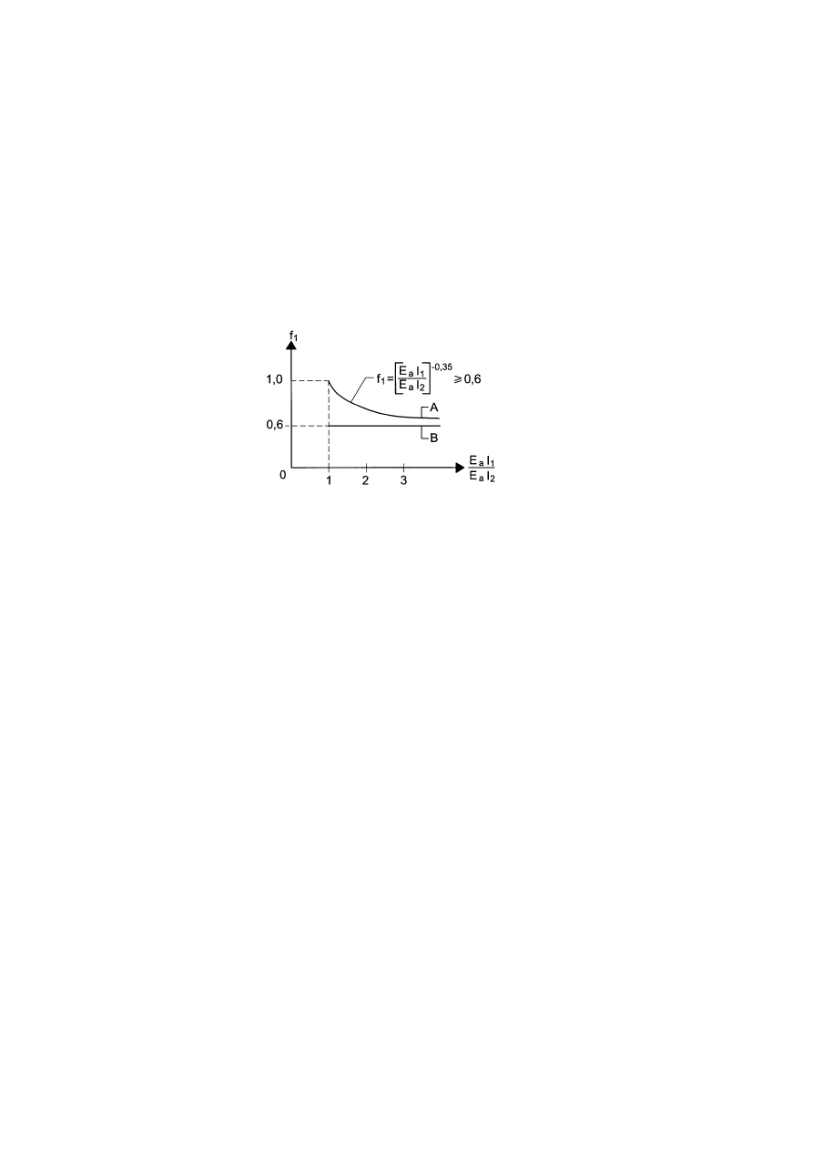
EN 1994-1-1: 2004 (E)
84
adjacent spans. Curve A may be used for internal spans only, when the loadings per unit length on
all spans are equal and the lengths of all spans do not differ by more than 25%. Otherwise the
approximate lower bound value f
1
= 0.6 (line B) should be used.
(7) For the calculation of deflection of un-propped beams, account may be taken of the influence of
local yielding of structural steel over a support by multiplying the bending moment at the support,
determined according to the methods given in this clause, with an additional reduction factor as
follows:
–
f
2
= 0.5 if f
y
is reached before the concrete slab has hardened;
–
f
2
= 0.7 if f
y
is reached after concrete has hardened.
This applies for the determination of the maximum deflection but not for pre-camber.
Figure 7.1 : Reduction factor for the bending moment at supports
(8) Unless specifically required by the client, the effect of curvature due to shrinkage of normal
weight concrete need not be included when the ratio of span to overall depth of the beam is not
greater than 20.
7.3.2 Vibration
(1) The dynamic properties of floor beams should satisfy the criteria in EN1990, A1.4.4.
7.4 Cracking of concrete
7.4.1 General
(1) For the limitation of crack width, the general considerations of EN 1992-1-1, 7.3.1(1) - (9) apply
to composite structures. The limitation of crack width depends on the exposure classes according to
EN 1992-1-l, 4.
(2) An estimation of crack width can be obtained from EN 1992-1-1, 7.3.4, where the stress
σ
s
should be calculated by taking into account the effects of tension stiffening. Unless a more precise
method is used,
σ
s
may be determined according to 7.4.3(3).
(3) As a simplified and conservative alternative, crack width limitation to acceptable width can be
achieved by ensuring a minimum reinforcement defined in 7.4.2, and bar spacing or diameters not
exceeding the limits defined in 7.4.3.
(4) In cases where beams in buildings are designed as simply supported although the slab is
continuous and the control of crack width is of no interest, the longitudinal reinforcement provided
within the effective width of the concrete slab according to 6.1.2 should be not less than:
– 0,4 % of the area of the concrete, for propped construction;
– 0,2 % of the area of concrete, for un-propped construction.

EN 1994-1-1:2004 (E)
85
The reinforcement in the beam designed as simply-supported should extend over a length of 0.25L
each side of an internal support, or 0,5L adjacent to a cantilever, where L is the length of the
relevant span or the length of the cantilever respectively. No account should be taken of any
profiled steel sheeting. The maximum spacing of the bars should be in accordance with 9.2.1(5) for
a composite slab, or with EN 1992-1-1, 9.3.1.1(3) for a solid concrete flange.
7.4.2 Minimum reinforcement
(1) Unless a more accurate method is used in accordance with EN 1992-1-1, 7.3.2(1), in all sections
without pre-stressing by tendons and subjected to significant tension due to restraint of imposed
deformations (e.g. primary and secondary effects of shrinkage), in combination or not with effects
of direct loading the required minimum reinforcement area A
s
for the slabs of composite beams is
given by:
s
ct
eff
ct,
c
s
s
/
σ
A
f
k
k
k
A
=
(7.1)
where :
f
ct,eff
is the mean value of the tensile strength of the concrete effective at the time when cracks
may first be expected to occur. Values of f
ct,eff
may be taken as those for f
ctm
, see
EN 1992-1-1, Table 3.1, or as f
lctm
, see Table 11.3.1, as appropriate, taking as the class the
strength at the time cracking is expected to occur. When the age of the concrete at cracking
cannot be established with confidence as being less than 28 days, a minimum tensile
strength of 3 N/mm
2
may be adopted;
k
is a coefficient which allows for the effect of non-uniform self-equilibrating stresses which
may be taken as 0.8;
k
s
is a coefficient which allows for the effect of the reduction of the normal force of the
concrete slab due to initial cracking and local slip of the shear connection, which may be
taken as 0.9;
k
c
is a coefficient which takes account of the stress distribution within the section immediately
prior to cracking and is given by:
0
.
1
3
.
0
)
2
(
/
1
1
o
c
c
≤
+
+
=
z
h
k
(7.2)
h
c
is the thickness of the concrete flange, excluding any haunch or ribs;
z
o
is the vertical distance between the centroids of the un-cracked concrete flange and the un-
cracked composite section, calculated using the modular ratio n
0
for short-term loading;
σ
s
is the maximum stress permitted in the reinforcement immediately after cracking. This may
be taken as its characteristic yield strength f
sk
. A lower value, depending on the bar size,
may however be needed to satisfy the required crack width limits. This value is given in
Table 7.1;
A
ct
is the area of the tensile zone (caused by direct loading and primary effects of shrinkage)
immediately prior to cracking of the cross section. For simplicity the area of the concrete
section within the effective width may be used.
EN 1994-1-1: 2004 (E)
86
Table 7.1 : Maximum bar diameters for high bond bars
Maximum bar diameter
φ
*
(mm) for design crack width
w
k
Steel stress
σ
s
(N/mm
2
)
w
k
=0.4mm
w
k
=0.3mm
w
k
=0.2mm
160 40
32
25
200 32
25
16
240 20
16
12
280 16
12
8
320 12
10
6
360 10
8
5
400 8
6
4
450 6
5
-
(2) The maximum bar diameter for the minimum reinforcement may be modified to a value
φ
given
by:
φ
=
φ
*
f
ct,eff
/ f
ct,0
(7.3)
where:
φ
*
is the maximum bar size given in Table 7.1;
f
ct,0
is a reference strength of 2.9 N/mm
2
.
(3) At least half of the required minimum reinforcement should be placed between mid-depth of the
slab and the face subjected to the greater tensile strain.
(4) For the determination of the minimum reinforcement in concrete flanges with variable depth
transverse to the direction of the beam the local depth should be used.
(5) For buildings the minimum reinforcement according to (1) and (2) should be placed where,
under the characteristic combination of actions, stresses are tensile.
(6) In buildings minimum lower longitudinal reinforcement for the concrete encasement of the web
of a steel I-section should be determined from expression (7.1) with kc taken as 0.6 and k taken as
0,8.
7.4.3 Control of cracking due to direct loading
(1) Where at least the minimum reinforcement given by 7.4.2 is provided, the limitation of crack
widths to acceptable values may generally be achieved by limiting bar spacing or bar diameters.
Maximum bar diameter and maximum bar spacing depend on the stress
σ
s
in the reinforcement and
the design crack width. Maximum bar diameters are given in Table 7.1 and maximum bar spacing
in Table 7.2.
(2) The internal forces should be determined by elastic analysis in accordance with Section 5 taking
into account the effects of cracking of concrete. The stresses in the reinforcement should be
determined taking into account effects of tension stiffening of concrete between cracks. Unless a
more precise method is used, the stresses may be calculated according to (3).
EN 1994-1-1:2004 (E)
87
Table 7.2 Maximum bar spacing for high bond bars
Maximum bar spacing (mm) for design crack
width w
k
Steel stress
σ
s
(N/mm
2
)
w
k
=0.4mm
w
k
=0.3mm
w
k
=0.2mm
160 300 300
200
200 300 250
150
240 250 200
100
280 200 150
50
320 150 100
-
360 100 50
-
(3) In composite beams where the concrete slab is assumed to be cracked and not pre-stressed by
tendons, stresses in reinforcement increase due to the effects of tension stiffening of concrete
between cracks compared with the stresses based on a composite section neglecting concrete. The
tensile stress in reinforcement
σ
s
due to direct loading may be calculated from:
s
o
s,
s
σ
∆
σ
σ
+
=
(7.4)
with:
s
st
ctm
s
4
,
0
ρ
α
σ
∆
f
=
(7.5)
a
a
st
I
A
I
A
=
α
(7.6)
where:
σ
s,o
is the stress in the reinforcement caused by the internal forces acting on the composite
section, calculated neglecting concrete in tension;
f
ctm
is the mean tensile strength of the concrete, for normal concrete taken as f
ctm
from EN
1992-1-1, Table 3.1 or for lightweight concrete as f
lctm
from Table 11.3.1;
ρ
s
is the reinforcement ratio, given by
ρ
s
= (A
s
/A
ct
) ;
A
ct
is the effective area of the concrete flange within the tensile zone; for simplicity the
area of the concrete section within the effective width should be used;
A
s
is the total area of all layers of longitudinal reinforcement within the effective area A
ct
;
A
, I are area and second moment of area, respectively, of the effective composite section
neglecting concrete in tension and profiled sheeting, if any;
A
a
, I
a
are the corresponding properties of the structural steel section.
(4) For buildings without pre-stressing by tendons the quasi-permanent combination of actions
normally should be used for the determination of
σ
s
.
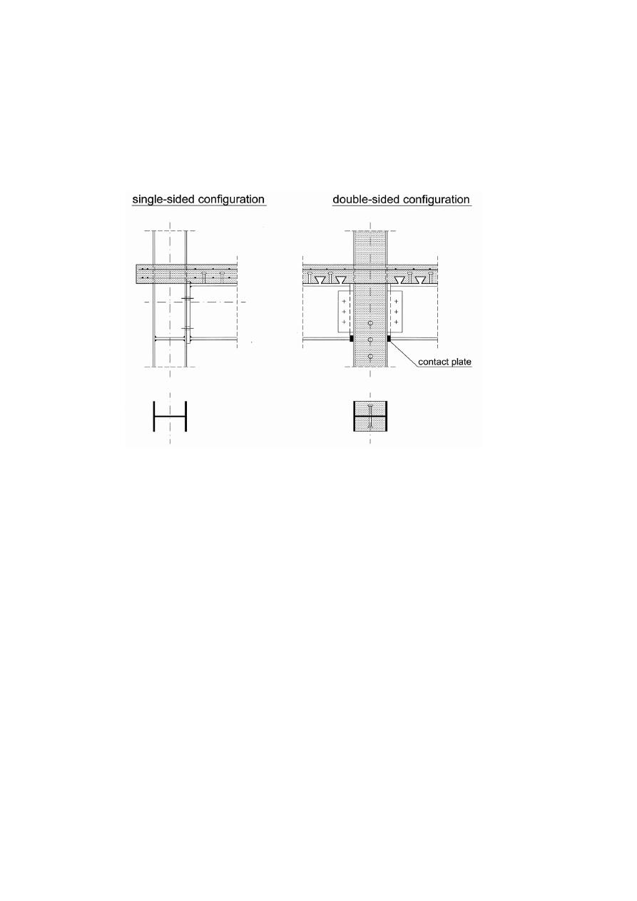
EN 1994-1-1: 2004 (E)
88
Section 8 Composite joints in frames for buildings
8.1 Scope
(1) A composite joint is defined in 1.5.2.8. Some examples are shown in Figure 8.1. Other joints in
composite frames should be designed in accordance with EN 1992-1-1 or EN 1993-1-8, as
appropriate.
Figure 8.1 : Examples of composite joints
(2) Section 8 concerns joints subject to predominantly static loading. It supplements or modifies EN
1993-1-8.
8.2 Analysis, modelling and classification
8.2.1 General
(1) The provisions in EN 1993-1-8, 5 for joints connecting H or I sections are applicable with the
modifications given in 8.2.2 and 8.2.3 below.
8.2.2 Elastic global analysis
(1) Where the rotational stiffness S
j
is taken as
η
/
j,ini
S
in accordance with EN 1993-1-8, 5.1.2, the
value of the stiffness modification coefficient
η
for a contact-plate connection should be taken as
1,5.
8.2.3 Classification of joints
(1) Joints should be classified in accordance with EN 1993-1-8, 5.2, taking account of composite
action.
(2) For the classification, the directions of the internal forces and moment should be considered.
(3) Cracking and creep in connected members may be neglected.

EN 1994-1-1:2004 (E)
89
8.3 Design methods
8.3.1 Basis and scope
(1) EN 1993-1-8, 6 may be used as a basis for the design of composite beam-to-column joints and
splices provided that the steelwork part of the joint is within the scope of that section.
(2) The structural properties of components assumed in design should be based on tests or on
analytical or numerical methods supported by tests.
NOTE: Properties of components are given in 8.4 and Annex A herein and in EN 1993-1-8, 6.
(3) In determining the structural properties of a composite joint, a row of reinforcing bars in tension
may be treated in a manner similar to a bolt-row in tension in a steel joint, provided that the
structural properties are those of the reinforcement.
8.3.2 Resistance
(1) Composite joints should be designed to resist vertical shear in accordance with relevant
provisions of EN 1993-1-8.
(2) The design resistance moment of a composite joint with full shear connection should be
determined by analogy to provisions for steel joints given in EN 1993-1-8, 6.2.7, taking account of
the contribution of reinforcement.
(3) The resistance of components should be determined from 8.4 below and EN 1993-1-8, 6.2.6,
where relevant.
8.3.3 Rotational stiffness
(1) The rotational stiffness of a joint should be determined by analogy to provisions for steel joints
given in EN 1993-1-8, 6.3.1, taking account of the contribution of reinforcement.
(2) The value of the coefficient
ψ
, see EN 1993-1-8, 6.3.1(6), should be taken as 1.7 for a contact-
plate joint.
8.3.4 Rotation capacity
(1) The influence of cracking of concrete, tension stiffening and deformation of the shear
connection should be considered in determining the rotation capacity.
(2) The rotation capacity of a composite joint may be demonstrated by experimental evidence.
Account should be taken of possible variations of the properties of materials from specified
characteristic values. Experimental demonstration is not required when using details which
experience has proved have adequate properties.
(3) Alternatively, calculation methods may be used, provided that they are supported by tests.
8.4 Resistance of components
8.4.1 Scope
(1) The resistance of the following basic joint components should be determined in accordance with
8.4.2 below:
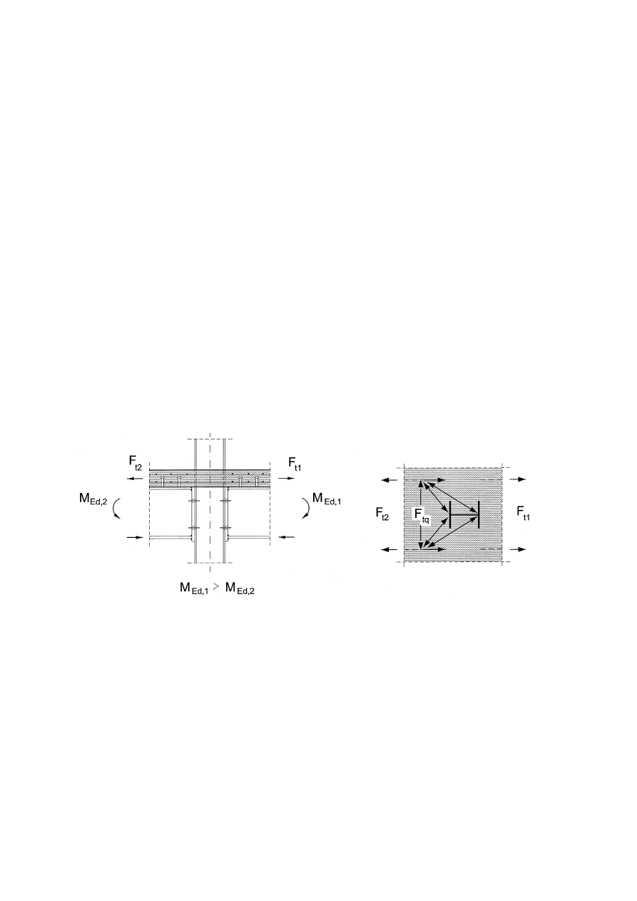
EN 1994-1-1: 2004 (E)
90
– longitudinal steel reinforcement in tension;
– steel contact plate in compression.
(2) The resistance of components identified in EN 1993-1-8 should be taken as given therein,
except as given in 8.4.3 below.
(3) The resistance of concrete encased webs in steel column sections should be determined in
accordance with 8.4.4 below.
8.4.2 Basic joint components
8.4.2.1 Longitudinal steel reinforcement in tension
(1) The effective width of the concrete flange should be determined for the cross-section at the
connection according to 5.4.1.2.
(2) It should be assumed that the effective area of longitudinal reinforcement in tension is stressed
to its design yield strength f
sd
.
(3) Where unbalanced loading occurs, a strut-tie model may be used to verify the introduction of the
forces in the concrete slab into the column, see Figure 8.2.
Figure 8.2 : Strut-tie model
(4) For a single-sided configuration designed as a composite joint, the effective longitudinal slab
reinforcement in tension should be anchored sufficiently well beyond the span of the beam to
enable the design tension resistance to be developed.
8.4.2.2 Steel contact plate in compression
(1) Where a height or breadth of the contact plate exceeds the corresponding dimension of the
compression flange of the steel section, the effective dimension should be determined assuming
dispersion at 45
o
through the contact plate.
(2) It should be assumed that the effective area of the contact plate in compression may be stressed
to its design yield strength f
yd
.

EN 1994-1-1:2004 (E)
91
8.4.3 Column web in transverse compression
(1) For a contact plate connection, the effective width of the column web in compression b
eff,c,wc
should be determined assuming dispersion at 45
° through the contact plate.
8.4.4 Reinforced components
8.4.4.1 Column web panel in shear
(1) Where the steel column web is encased in concrete, see Figure 6.17b, the design shear resistance
of the panel, determined in accordance with EN 1993-1-8, 6.2.6.1 may be increased to allow for the
encasement.
(2) For a single-sided joint, or a double-sided joint in which the beam depths are similar, the design
shear resistance of concrete encasement to the column web panel V
wp,c,Rd
should be determined
using:
V
wp,c,Rd
= 0.85
ν
A
c
f
cd
sin
θ
(8.1)
with:
A
c
= 0.8 (b
c
- t
w
) (h - 2t
f
) cos
θ
(8.2)
θ
= arctan [(h - 2t
f
) / z]
(8.3)
where:
b
c
is the breadth of the concrete encasement;
h
is the depth of the column section;
t
f
is the column flange thickness;
t
w
is the column web thickness;
z
is the lever arm, see EN 1993-1-8, 6.2.7.1 and Figure 6.15.
(3) The reduction factor
ν
to allow for the effect of longitudinal compression in the column on the
design resistance of the column web panel in shear should be determined using:
1
.
1
2
1
55
.
0
Rd
,
pl
Ed
≤
+
=
ν
N
N
(8.4)
where:
N
Ed
is the design compressive normal force in the column;
N
p1,Rd
is the design plastic resistance of the column’s cross-section including the encasement,
see 6.7.3.2.
8.4.4.2 Column web in transverse compression
(1) Where the steel column web is encased in concrete the design resistance of the column web in
compression, determined in accordance with EN 1993-1-8, 6.2.6.2 may be increased to allow for
the encasement.
(2) The design resistance of the concrete encasement to the column web in transverse
compression
Rd
c,
wc,
c,
F
should be determined using:
cd
w
c
c
eff,
c
wc,
Rd
c,
wc,
c,
)
(
85
.
0
f
t
b
t
k
F
−
=
(8.5)

EN 1994-1-1: 2004 (E)
92
where:
c
eff,
t
is the effective length of concrete, determined in a similar manner to the effective
width b
eff,c,wc
defined in EN 1993-1-8, 6.2.6.2.
(3) Where the concrete encasement is subject to a longitudinal compressive stress, its effect on the
resistance of the concrete encasement in transverse compression may be allowed for by multiplying
the value of F
c,wc,c,Rd
by a factor k
wc,c
given by:
0
.
2
3
.
3
3
.
1
cd
Ed
c,
com,
c
wc,
≤
σ
+
=
f
k
(8.6)
where:
σ
com,c,Ed
is the longitudinal compressive stress in the encasement due to the design normal
force N
Ed
.
In the absence of a more accurate method,
σ
com,c,Ed
may be determined from the relative
contribution of the concrete encasement to the plastic resistance of the column section in
compression N
pl,Rd
, see 6.7.3.2.
Section 9 Composite slabs with profiled steel sheeting for buildings
9.1 General
9.1.1 Scope
(1)P This Section deals with composite floor slabs spanning only in the direction of the ribs.
Cantilever slabs are included. It applies to designs for building structures where the imposed loads
are predominantly static, including industrial buildings where floors may be subject to moving
loads.
(2)P The scope is limited to sheets with narrowly spaced webs.
NOTE: Narrowly spaced webs are defined by an upper limit on the ratio b
r
/ b
s
, see Figure 9.2. The value for the
limit may be given in the National Annex. The recommended value is 0.6.
(3)P For structures where the imposed load is largely repetitive or applied abruptly in such a
manner as to produce dynamic effects, composite slabs are permitted, but special care shall be taken
over the detailed design to ensure that the composite action does not deteriorate in time.
(4)P Slabs subject to seismic loading are not excluded, provided an appropriate design method for
the seismic conditions is defined for the particular project or is given in another Eurocode.
(5) Composite slabs may be used to provide lateral restraint to the steel beams and to act as a
diaphragm to resist horizontal actions, but no specific rules are given in this Standard. For
diaphragm action of the profiled steel sheeting while it is acting as formwork the rules given in
EN1993-1-3, 10 apply.
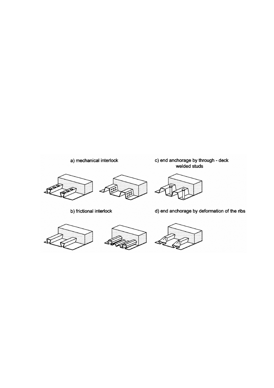
EN 1994-1-1:2004 (E)
93
9.1.2 Definitions
9.1.2.1 Types of shear connection
The profiled steel sheet shall be capable of transmitting horizontal shear at the interface between the
sheet and the concrete; pure bond between steel sheeting and concrete is not considered effective
for composite action. Composite behaviour between profiled sheeting and concrete shall be ensured
by one or more of the following means, see Figure 9.1:
a) mechanical interlock provided by deformations in the profile (indentations or
embossments);
b)
frictional interlock for profiles shaped in a re-entrant form;
c) end anchorage provided by welded studs or another type of local connection between the
concrete and the steel sheet, only in combination with (a) or (b);
d) end anchorage by deformation of the ribs at the end of the sheeting, only in combination
with (b).
Other means are not excluded but are not within the scope of this Standard.
Figure 9.1 : Typical forms of interlock in composite slabs
9.1.2.2 Full shear connection and partial shear connection
A span of a slab has full shear connection when increase in the resistance of the longitudinal shear
connection would not increase the design bending resistance of the member. Otherwise, the shear
connection is partial.
9.2 Detailing provisions
9.2.1 Slab thickness and reinforcement
(1)P The overall depth of the composite slab h shall be not less than 80 mm. The thickness of
concrete h
c
above the main flat surface of the top of the ribs of the sheeting shall be not less than
40 mm.
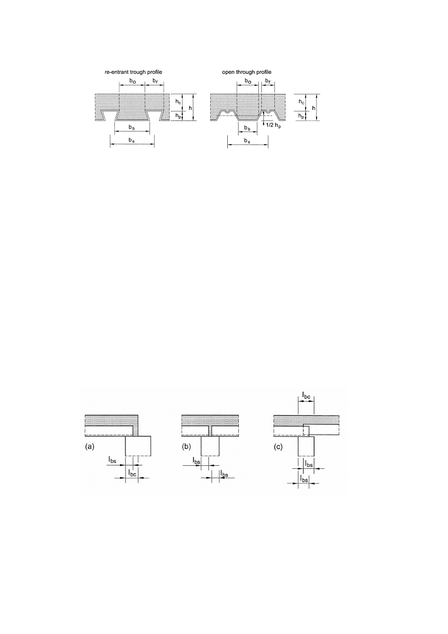
EN 1994-1-1: 2004 (E)
94
Figure 9.2 : Sheet and slab dimensions
(2)P If the slab is acting compositely with the beam or is used as a diaphragm, the total depth shall
be not less than 90 mm and h
c
shall be not less than 50 mm.
(3)P Transverse and longitudinal reinforcement shall be provided within the depth h
c
of the
concrete.
(4) The amount of reinforcement in both directions should be not less than 80 mm
2
/m.
(5) The spacing of the reinforcement bars should not exceed 2h and 350 mm, whichever is the
lesser.
9.2.2 Aggregate
(1)P The nominal size of the aggregate depends on the smallest dimension in the structural element
within which concrete is poured, and shall not exceed the least of:
–
0,40 h
c
, see Figure 9.2;
–
b
0
/3, where b
0
is the mean width of the ribs (minimum width for re-entrant profiles), see
Figure 9.2;
–
31,5 mm (sieve C 31,5).
NOTE: Overlapping of some sheeting profiles is impractical.
Figure 9.3 : Minimum bearing lengths
9.2.3 Bearing requirements
(1)P The bearing length shall be such that damage to the slab and the bearing is avoided; that
fastening of the sheet to the bearing can be achieved without damage to the bearing and that
collapse cannot occur as a result of accidental displacement during erection.

EN 1994-1-1:2004 (E)
95
(2) The bearing lengths l
bc
and l
bs
as indicated in Figure 9.3 should not be less than the following
limiting values:
–
for composite slabs bearing on steel or concrete: l
bc
= 75 mm and l
bs
= 50 mm;
–
for composite slabs bearing on other materials: l
bc
= 100 mm and l
bs
= 70 mm.
9.3 Actions and action effects
9.3.1 Design situations
(1)P All relevant design situations and limit states shall be considered in design so as to ensure an
adequate degree of safety and serviceability.
(2)P The following situations shall be considered:
a) Profiled steel sheeting as shuttering: Verification is required for the behaviour of the
profiled steel sheeting while it is acting as formwork for the wet concrete. Account shall
be taken of the effect of props, if any.
b) Composite slab: Verification is required for the floor slab after composite behaviour has
commenced and any props have been removed.
9.3.2 Actions for profiled steel sheeting as shuttering
(1)The following loads should be taken into account in calculations for the steel deck as shuttering:
–
weight of concrete and steel deck;
–
construction loads including local heaping of concrete during construction, in accordance
with EN 1991-1-6, 4.11.2;
–
storage load, if any;
–
“ponding” effect (increased depth of concrete due to deflection of the sheeting).
(2) If the central deflection
δ
of the sheeting under its own weight plus that of the wet concrete,
calculated for serviceability, is less than 1/10 of the slab depth, the ponding effect may be ignored in
the design of the steel sheeting. If this limit is exceeded, this effect should be allowed for. It may be
assumed in design that the nominal thickness of the concrete is increased over the whole span by 0.7
δ
.
9.3.3 Actions for composite slab
(1) Loads and load arrangements should be in accordance with EN 1991-1-1.
(2) In design checks for the ultimate limit state, it may be assumed that the whole of the loading
acts on the composite slab, provided this assumption is also made in design for longitudinal shear.
9.4 Analysis for internal forces and moments
9.4.1 Profiled steel sheeting as shuttering
(1) The design of the profiled steel sheeting as shuttering should be in accordance with
EN1993-1-3.
(2) Plastic redistribution of moments should not be allowed when temporary supports are used.
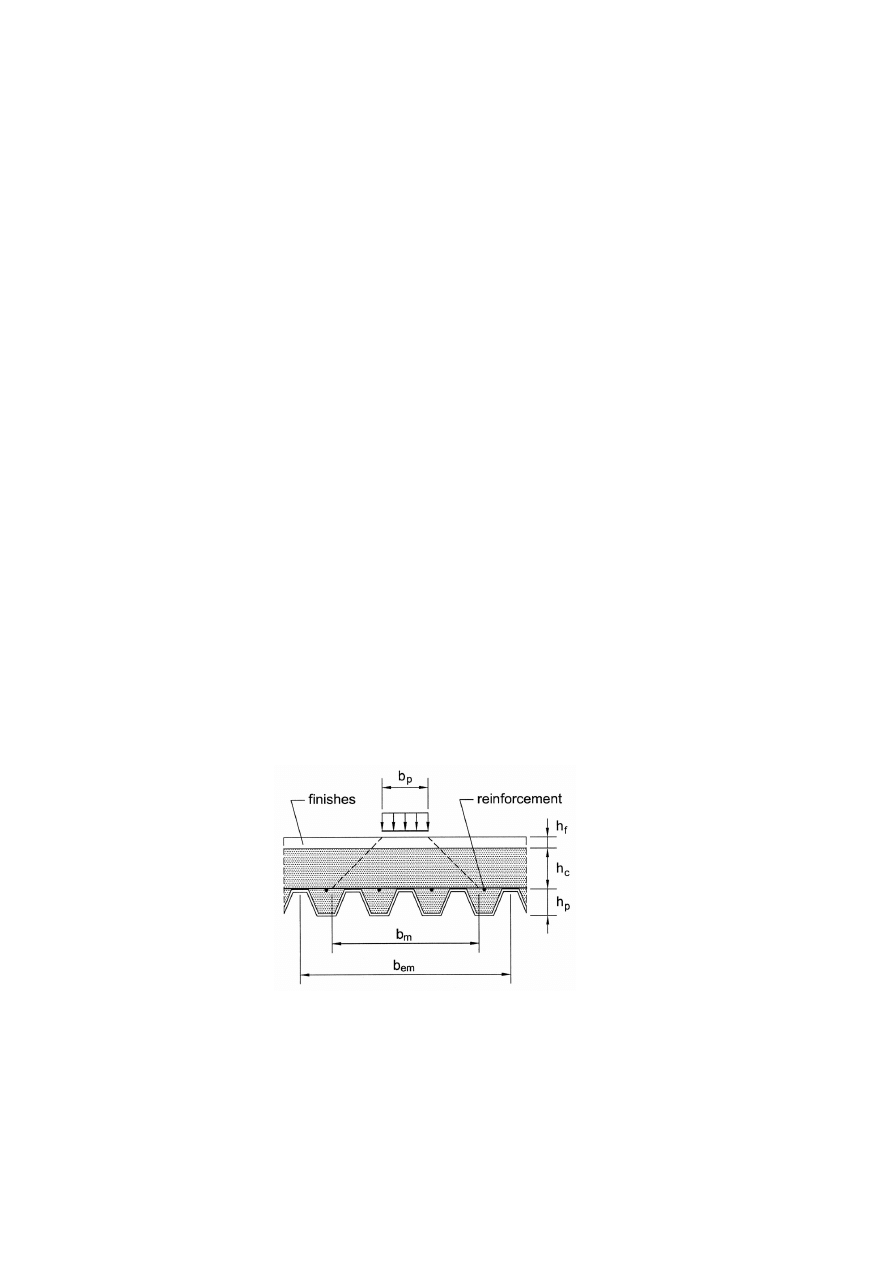
EN 1994-1-1: 2004 (E)
96
9.4.2 Analysis of composite slab
(1) The following methods of analysis may be used for ultimate limit states:
a) Linear elastic analysis with or without redistribution;
b) Rigid plastic global analysis provided that it is shown that sections where plastic rotations
are required have sufficient rotation capacity;
c) Elastic-plastic analysis, taking into account the non-linear material properties.
(2) Linear methods of analysis should be used for serviceability limit states.
(3) If the effects of cracking of concrete are neglected in the analysis for ultimate limit states, the
bending moments at internal supports may optionally be reduced by up to 30%, and corresponding
increases made to the sagging bending moments in the adjacent spans.
(4) Plastic analysis without any direct check on rotation capacity may be used for the ultimate limit
state if reinforcing steel of class C in accordance with EN 1992-1-1, Annex C is used and the span
is not greater than 3,0 m.
(5) A continuous slab may be designed as a series of simply supported spans. Nominal
reinforcement in accordance with 9.8.1 should be provided over intermediate supports.
9.4.3 Effective width of composite slab for concentrated point and line loads
(1) Where concentrated point or line loads are to be supported by the slab, they may be considered
to be distributed over an effective width, unless a more exact analysis is carried out.
(2) Concentrated point or line loads parallel to the span of the slab should be considered to be
distributed over a width b
m
, measured immediately above the ribs of the sheeting, see Figure 9.4,
and given by:
b
m
= b
p
+ 2 (h
c
+ h
f
)
(9.1)
Figure 9.4 : Distribution of concentrated load
(3) For concentrated line loads perpendicular to the span of the slab, expression (9.1) should be
used for b
m
, with b
p
taken as the length of the concentrated line load.
(4) If h
p
/ h does not exceed 0.6 the width of the slab considered to be effective for global analysis
and for resistance may for simplification be determined with expressions (9.2) to (9.4):

EN 1994-1-1:2004 (E)
97
(a) for bending and longitudinal shear:
–
for simple spans and exterior spans of continuous slabs
width
slab
1
2
p
p
m
em
≤
−
+
=
L
L
L
b
b
(9.2)
–
for interior spans of continuous slabs
width
slab
1
33
.
1
p
p
m
em
≤
−
+
=
L
L
L
b
b
(9.3)
(b) for vertical shear:
width
slab
1
p
p
m
ev
≤
−
+
=
L
L
L
b
b
(9.4)
where:
L
p
is the distance from the centre of the load to the nearest support;
L
is the span length.
(5) If the characteristic imposed loads do not exceed the following values, a nominal transverse
reinforcement may be used without calculation:
– concentrated load: 7.5 kN;
– distributed load: 5.0 kN/m
2
.
This nominal transverse reinforcement should have a cross-sectional area of not less than 0.2% of
the area of structural concrete above the ribs, and should extend over a width of not less than b
em
as
calculated in this clause. Minimum anchorage lengths should be provided beyond this width in
accordance with EN 1992-1-1. Reinforcement provided for other purposes may fulfil all or part of
this rule.
(6) Where the conditions in (5) are not satisfied, the distribution of bending moments caused by line
or point loads should be determined and adequate transverse reinforcement determined using
EN 1992-1-1.
9.5 Verification of profiled steel sheeting as shuttering for ultimate limit states
(1) Verification of the profiled steel sheeting for ultimate limit states should be in accordance with
EN 1993-1-3. Due consideration should be given to the effect of embossments or indentations on
the design resistances.
9.6 Verification of profiled steel sheeting as shuttering for serviceability limit states
(1) Section properties should be determined in accordance with EN 1993-1-3.
(2) The deflection
δ
s
of the sheeting under its own weight plus the weight of wet concrete,
excluding the construction load, should not exceed
δ
s,max
.
NOTE: Values for
δ
s,max
may be given in the National Annex. The recommended value is L/180 where L is the
effective span between supports (props being supports in this context).
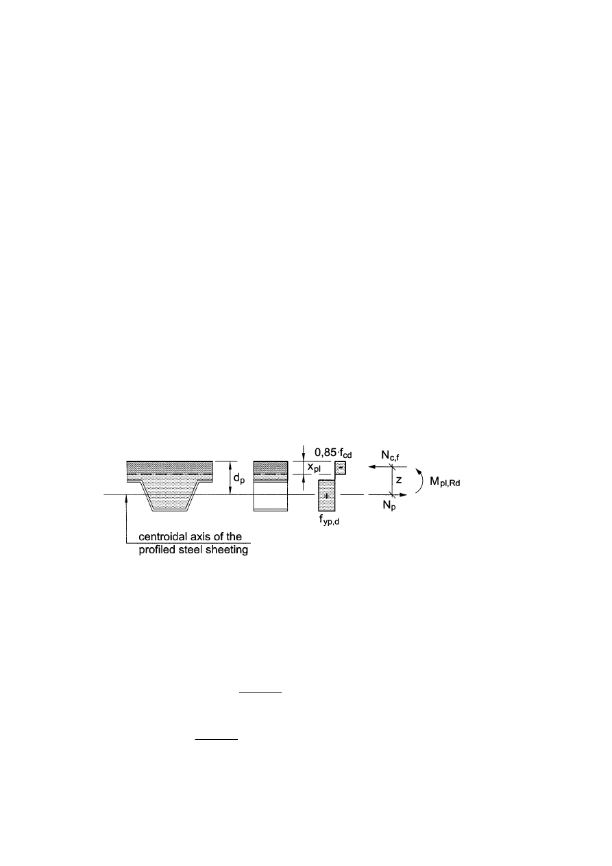
EN 1994-1-1: 2004 (E)
98
9.7 Verification of composite slabs for the ultimate limit states
9.7.1 Design criterion
(1)P The design values of internal forces shall not exceed the design values of resistance for the
relevant ultimate limit states.
9.7.2 Flexure
(1) In case of full shear connection the bending resistance M
Rd
of any cross section should be
determined by plastic theory in accordance with 6.2.1.2(1) but with the design yield strength of the
steel member (sheeting) taken as that for the sheeting, f
yp,d
.
(2)P In hogging bending the contribution of the steel sheeting shall only be taken into account
where the sheet is continuous and when for the construction phase redistribution of moments by
plastification of cross-sections over supports has not been used.
(3) For the effective area A
pe
of the steel sheeting, the width of embossments and indentations in the
sheet should be neglected, unless it is shown by tests that a larger area is effective.
(4) The effect of local buckling of compressed parts of the sheeting should be taken into account by
using effective widths not exceeding twice the limiting values given in EN 1993-1-1, Table 5.2 for
Class 1 steel webs.
(5) The sagging bending resistance of a cross-section with the neutral axis above the sheeting
should be calculated from the stress distribution in Figure 9.5.
Figure 9.5 : Stress distribution for sagging bending if the neutral axis is above the steel sheeting
(6) The sagging bending resistance of a cross-section with the neutral axis in the sheeting should be
calculated from the stress distribution in Figure 9.6.
For simplification z and M
pr
may be determined with the following expressions respectively:
z
= h - 0.5 h
c
– e
p
+ (e
p
- e)
d
yp,
pe
cf
f
A
N
(9.5)
M
pr
= 1.25 M
pa
−
d
yp,
pe
cf
1
f
A
N
≤ M
pa
(9.6)
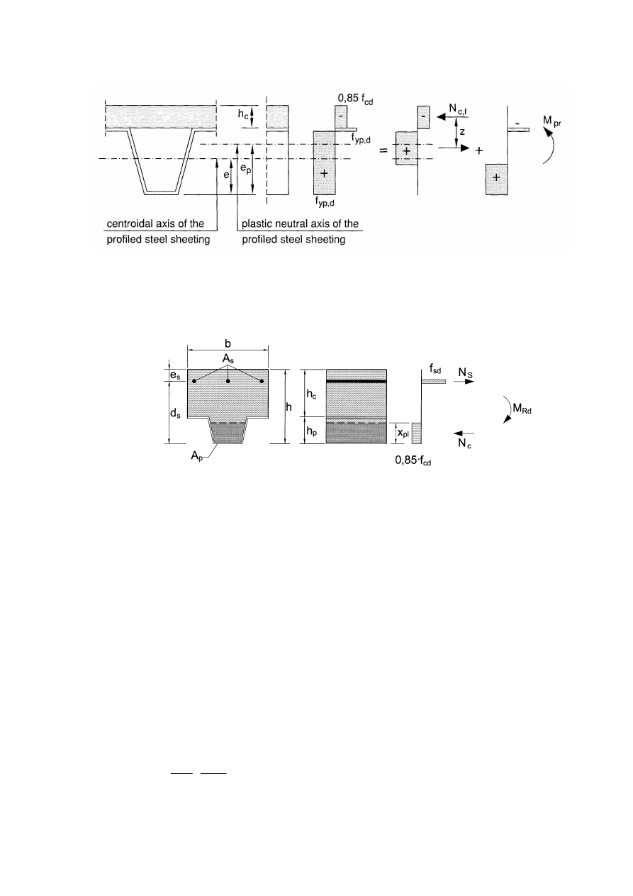
EN 1994-1-1:2004 (E)
99
Figure 9.6 : Stress distribution for sagging bending if neutral axis is in the steel sheeting
(7) If the contribution of the steel sheeting is neglected the hogging bending resistance of a cross-
section should be calculated from the stress distribution in Figure 9.7.
Figure 9.7 : Stress distribution for hogging bending
9.7.3 Longitudinal shear for slabs without end anchorage
(1)P The provisions in this clause 9.7.3 apply to composite slabs with mechanical or frictional
interlock (types (a) and (b) as defined in 9.1.2.1).
(2) The design resistance against longitudinal shear should be determined by the m-k method, see
(4) and (5) below, or by the partial connection method as given in (7) – (10). The partial connection
method should be used only for composite slabs with a ductile longitudinal shear behaviour.
(3) The longitudinal shear behaviour may be considered as ductile if the failure load exceeds the
load causing a recorded end slip of 0.1 mm by more than 10%. If the maximum load is reached at a
midspan deflection exceeding L/50, the failure load should be taken as the load at the midspan
deflection of L/50.
(4) If the m-k method is used it should be shown that the maximum design vertical shear V
Ed
for a
width of slab b does not exceed the design shear resistance V
l,Rd
determined from the following
expression:
+
=
k
L
b
A
m
d
b
V
s
p
VS
p
Rd
l,
γ
(9.7)

EN 1994-1-1: 2004 (E)
100
where:
b
, d
p
are in mm;
A
p
is the nominal cross-section of the sheeting in mm
2
;
m, k
are design values for the empirical factors in N/mm
2
obtained from slab tests meeting
the basic requirements of the m-k method;
L
s
is the shear span in mm and defined in (5) below;
γ
VS
is the partial safety factor for the ultimate limit state.
NOTE 1: The value for
γ
VS
may be given in the National Annex. The recommended value for
γ
VS
is 1.25.
NOTE 2: The test method as given in Annex B may be assumed to meet the basic requirements of the m-k
method
NOTE 3: In expression (9.7) the nominal cross-section A
p
is used because this value is normally used in the test
evaluation to determine m and k.
(5) For design, L
s
should be taken as:
– L/4 for a uniform load applied to the entire span length;
– the distance between the applied load and the nearest support for two equal and
symmetrically placed loads;
– for
other
loading
arrangements, including a combination of distributed and asymmetrical
point loads, an assessment should be made based upon test results or by the following
approximate calculation. The shear span should be taken as the maximum moment divided
by the greater vertical shear force adjacent to the supports for the span considered.
(
6) Where the composite slab is designed as continuous, it is permitted to use an equivalent isostatic
span for the determination of the resistance. The span length should be taken as:
– 0.8L for internal spans;
– 0.9L for external spans.
(7) If the partial connection method is used it should be shown that at any cross-section the design
bending moment M
Ed
does not exceed the design resistance M
Rd
.
(8) The design resistance M
Rd
should be determined as given in 9.7.2(6) but with N
cf
replaced by:
N
c
=
τ
u,Rd
b
L
x
≤ N
cf
(9.8)
and:
( )
d
yp,
pe
c
p
p
pl
5
.
0
f
A
N
e
e
e
x
h
z
−
+
−
−
=
(9.9)
where:
τ
u,Rd
is the design shear strength (
τ
u,Rk
/
γ
Vs
) obtained from slab tests meeting the basic
requirements of the partial interaction method;
L
x
is the distance of the cross-section being considered to the nearest support.
NOTE 1: The value for
γ
VS
may be given in the National Annex. The recommended value for
γ
VS
is 1,25.
NOTE 2: The test method as given in Annex B may be assumed to meet the basic requirements for the
determination of
τ
u,Rd

EN 1994-1-1:2004 (E)
101
(9) In expression (9.8) N
c
may be increased by
Ed
R
µ
provided that
τ
u,Rd
is determined taking into
account the additional longitudinal shear resistance caused by the support reaction, where:
R
Ed
is the support reaction and
µ
is a nominal factor.
NOTE: The value for
µ may be given in the National Annex. The recommended value for µ is 0.5.
(10) In the partial connection method additional bottom reinforcement may be taken into account.
9.7.4 Longitudinal shear for slabs with end anchorage
(1) Unless a contribution to longitudinal shear resistance by other shear devices is shown by testing,
the end anchorage of type (c), as defined in 9.1.2.1, should be designed for the tensile force in the
steel sheet at the ultimate limit state.
(2) The design resistance against longitudinal shear of slabs with end anchorage of types (c) and (d),
as defined in 9.1.2.1, may be determined by the partial connection method as given in 9.7.3(7) with
N
c
increased by the design resistance of the end anchorage.
(3) The design resistance P
pb.Rd
of a headed stud welded through the steel sheet used for end
anchorage should be taken as the smaller of the design shear resistance of the stud in accordance
with 6.6.4.2 or the bearing resistance of the sheet determined with the following expression:
P
pb,Rd
= k
ϕ
d
do
t f
yp,d
(9.10)
with:
k
ϕ
= 1 + a / d
do
≤ 6.0
(9.11)
where:
d
do
is the diameter of the weld collar which may be taken as 1,1 times the diameter of
the shank of the stud;
a
is the distance from the centre of the stud to the end of the sheeting, to be not less
than 1.5 d
do
;
t
is the thickness of the sheeting.
9.7.5 Vertical shear
(1) The vertical shear resistance V
v,Rd
of a composite slab over a width equal to the distance
between centres of ribs, should be determined in accordance with EN 1992-1-1, 6.2.2.
9.7.6 Punching shear
(1) The punching shear resistance V
p,Rd
of a composite slab at a concentrated load should be
determined in accordance with EN 1992-1-1, 6.4.4, where the critical perimeter should be
determined as shown in Figure 9.8.
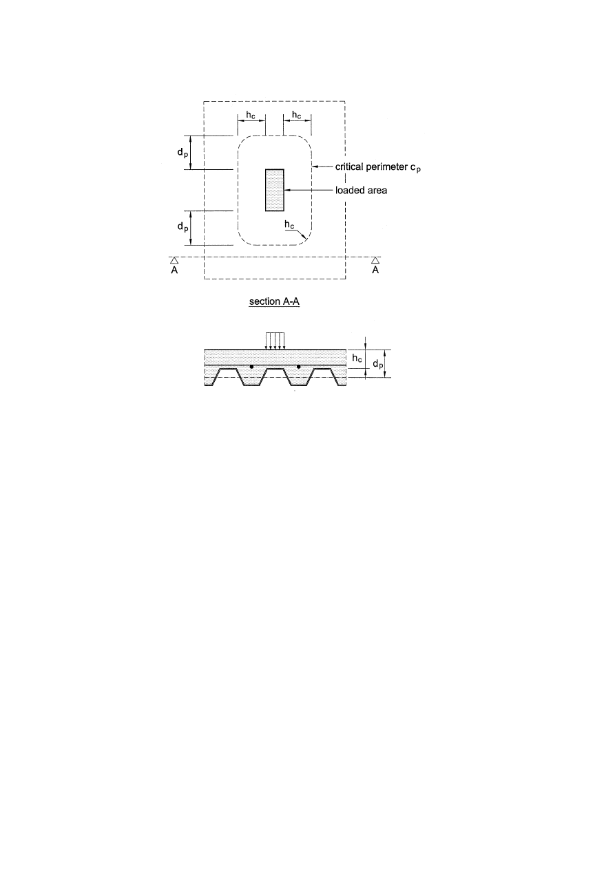
EN 1994-1-1: 2004 (E)
102
Figure 9.8 : Critical perimeter for punching shear
9.8 Verification of composite slabs for serviceability limit states
9.8.1 Control of cracking of concrete
(1) The crack width in hogging moment regions of continuous slabs should be checked in
accordance with EN 1992-1-1, 7.3.
(2) Where continuous slabs are designed as simply-supported in accordance with 9.4.2(5), the
cross-sectional area of the anti-crack reinforcement above the ribs should be not less than 0.2% of
the cross-sectional area of the concrete above the ribs for un-propped construction and 0.4% of this
cross-sectional area for propped construction.
9.8.2 Deflection
(1) EN 1990, 3.4.3, applies.
(2) Deflections due to loading applied to the steel sheeting alone should be calculated in accordance
with EN 1993-1-3, Section 7.
(3) Deflections due to loading applied to the composite member should be calculated using elastic
analysis in accordance with Section 5, neglecting the effects of shrinkage.
(4) Calculations of deflections may be omitted if both:
–
the span to depth ratio does not exceed the limits given in EN 1992-1-1, 7.4, for lightly
stressed concrete, and
–
the condition of (6) below, for neglect of the effects of end slip, is satisfied.

EN 1994-1-1:2004 (E)
103
(5) For an internal span of a continuous slab where the shear connection is as defined in 9.1.2.1(a),
(b) or (c), the deflection may be determined using the following approximations:
–
the second moment of area may be taken as the average of the values for the cracked and
un-cracked section;
–
for concrete, an average value of the modular ratio for both long- and short-term effects
may be used.
(6) For external spans, no account need be taken of end slip if the initial slip load in tests (defined as
the load causing an end slip of 0,5 mm) exceeds 1.2 times the design service load.
(7) Where end slip exceeding 0.5 mm occurs at a load below 1.2 times the design service load, then
end anchors should be provided. Alternatively deflections should be calculated including the effect
of end slip.
(8) If the influence of the shear connection between the sheeting and the concrete is not known from
experimental verification for a composite floor with end anchorage, the design should be simplified
to an arch with a tensile bar. From that model, the lengthening and shortening gives the deflection
that should be taken into account.

EN 1994-1-1: 2004 (E)
104
Annex A (Informative)
Stiffness of joint components in buildings
A.1 Scope
(1) The stiffness of the following basic joint components may be determined in accordance with
A.2.1 below:
–
longitudinal steel reinforcement in tension;
–
steel contact plate in compression.
(2) Stiffness coefficients k
i
are defined by EN 1993-1-8, expression (6.27). The stiffness of
components identified in that Standard may be taken as given therein, except as given in A.2.2
below.
(3) The stiffness of concrete encased webs in steel column sections may be determined in
accordance with A.2.3 below.
(4) The influence of slip of the shear connection on joint stiffness may be determined in accordance
with A.3.
A.2 Stiffness coefficients
A.2.1 Basic joint components
A.2.1.1 Longitudinal steel reinforcement in tension
(1) The stiffness coefficient k
s,r
for a row r may be obtained from Table A.1.
A.2.1.2 Steel contact plate in compression
(1) The stiffness coefficient may be taken as equal to infinity.
A.2.2 Other components in composite joints
A.2.2.1 Column web panel in shear
(1) For an unstiffened panel in a joint with a steel contact plate connection, the stiffness coefficient
k
1
may be taken as 0,87 times the value given in EN 1993-1-8, Table 6.11.
A.2.2.2 Column web in transverse compression
(1) For an un-stiffened web and a contact plate connection, the stiffness coefficient k
2
may be
determined from:
c
wc
wc
c,
ff,
2
2
,
0
d
t
b
k
e
=
(A.1)
where:
b
eff,c,wc
is the effective width of the column web in compression, see 8.4.3.1.
Other terms are defined in EN 1993-1-8, 6.
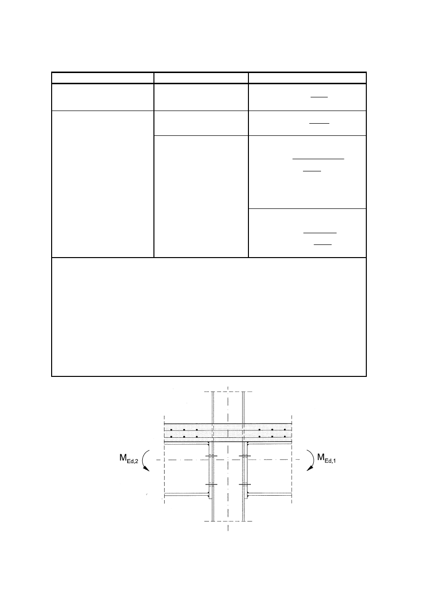
EN 1994-1-1:2004 (E)
105
Table A.1 : Stiffness coefficient k
s,r
Configuration Loading Stiffness
coefficient
Single-sided
-
h
A
k
6
,
3
r
s,
r
s,
=
M
Ed,1
= M
Ed,2
)
2
/
(
r
s,
r
s,
h
A
k
=
For the joint with M
Ed,1
:
+
+
=
β
r
s,
r
s,
2
1
K
h
A
k
β
with:
β
K
(
)
2
,
7
9
,
8
3
,
4
2
+
−
=
β
β
β
Double-sided
M
Ed,1
> M
Ed,2
For the joint with M
Ed,2
:
−
=
2
1
r
s,
r
s,
β
h
A
k
A
s,r
is the cross-sectional area of the longitudinal reinforcement in row r within the
effective width of the concrete flange determined for the cross-section at the
connection according to 5.4.1.2;
M
Ed,i
is the design bending moment applied to a connection i by a connected beam,
see Figure A.1;
h
is the depth of the column's steel section, see Figure 6.17;
β
is the transformation parameter given in EN 1993-1-8, 5.3.
Note: The stiffness coefficient for M
Ed,1
= M
Ed,2
is applicable to a double-sided beam-to-beam joint
configuration under the same loading condition, provided that the breadth of the flange of the supporting
primary beam replaces the depth h of the column section.
Figure A.1 : Joints with bending moments

EN 1994-1-1: 2004 (E)
106
A.2.3 Reinforced components
A.2.3.1 Column web panel in shear
(1) Where the steel column web is encased in concrete, see Figure 6.17b, the stiffness of the panel
may be increased to allow for the encasement. The addition k
1,c
to the stiffness coefficient k
1
may be
determined from:
z
h
b
E
E
k
β
c
c
a
cm
c
,
1
06
,
0
=
(A.2)
where:
E
cm
is the modulus of elasticity for concrete;
z
is the lever arm, see EN 1993-1-8, Figure 6.15.
A.2.3.2 Column web in transverse compression
(1) Where the steel column web is encased in concrete, see Figure 6.17b, the stiffness of the column
web in compression may be increased to allow for the encasement.
(2) For a contact plate connection, the addition k
2,c
to the stiffness coefficient k
2
may be determined
from:
c
c
c
eff
a
cm
c
h
b
t
E
E
k
,
,
2
13
,
0
=
(A.3)
where:
t
eff,c
is the effective thickness of concrete, see 8.4.4.2(2).
(3) For an end plate connection, the addition k
2,c
may be determined from:
c
c
c
eff
a
cm
c
h
b
t
E
E
k
,
,
2
5
,
0
=
(A.4)
A.3 Deformation of the shear connection
(1) Unless account is taken of deformation of the shear connection by a more exact method, the
influence of slip on the stiffness of the joint may be determined by (2) - (5) below.
(2) The stiffness coefficient k
s,r
, see A.2.1.1, may be multiplied by the reduction factor, k
slip
:
k
slip
=
sc
r
s,
s
1
1
K
k
E
+
(A.5)
with:
s
s
sc
sc
+
1
1
-
-
d
h
k
N
K
=
ξ
ν
ν
(A.6)

EN 1994-1-1:2004 (E)
107
( )
a
a
s
sc
I
E
d
k
N
v
2
1
l
ξ
+
=
(A.7)
s
s
2
s
a
a
A
E
d
I
E
=
ξ
(A.8)
where:
h
s
is the distance between the longitudinal reinforcing bars in tension and the centre of
compression; see EN 1993-1-8, Figure 6.15 for the centre of compression;
d
s
is the distance between the longitudinal reinforcing bars in tension and the centroid
of the beam's steel section;
I
a
is the second moment of area of the beam's steel section;
l
is the length of the beam in hogging bending adjacent to the joint, which in a braced
frame may be taken as 15% of the length of the span;
N
is the number of shear connectors distributed over the length l;
k
sc
is the stiffness of one shear connector.
(3) The stiffness of the shear connector,
sc
k , may be taken as
s
P /
7
,
0
Rk
, where:
P
Rk
is the characteristic resistance of the shear connector;
s
is the slip, determined from push tests in accordance with Annex B, at a load of 0,7
P
Rk
.
(4) Alternatively, for a solid slab or for a composite slab in which the reduction factor
k
t
is unity,
see 6.6.4.2, the following approximate values may be assumed for
k
sc
:
–
for 19 mm diameter headed studs:
100 kN/mm
–
for cold-formed angles of 80mm to 100mm height:
70 kN/mm.
(5) For a composite joint with more than a single layer of reinforcement considered effective in
tension, (2) above is applicable provided that the layers are represented by a single layer of
equivalent cross-sectional area and equivalent distances from the centre of compression and the
centroid of the beam’s steel section.

EN 1994-1-1: 2004 (E)
108
Annex B (Informative)
Standard tests
B.1 General
(1)
In this Standard rules are given for:
a)
tests on shear connectors in B.2 and
b)
testing of composite floor slabs in B.3.
NOTE: These standard testing procedures are included in the absence of Guidelines for ETA. When such
Guidelines have been developed this Annex can be withdrawn.
B.2 Tests on shear connectors
B.2.1 General
(1) Where the design rules in 6.6 are not applicable, the design should be based on tests, carried out
in a way that provides information on the properties of the shear connection required for design in
accordance with this Standard.
(2) The variables to be investigated include the geometry and the mechanical properties of the
concrete slab, the shear connectors and the reinforcement.
(3) The resistance to loading, other than fatigue, may be determined by push tests in accordance
with the requirements in this Annex.
(4) For fatigue tests the specimen should also be prepared in accordance with this Annex.
B.2.2 Testing arrangements
(1) Where the shear connectors are used in T-beams with a concrete slab of uniform thickness, or
with haunches complying with 6.6.5.4, standard push tests may be used. In other cases specific push
tests should be used.
(2) For standard push tests the dimensions of the test specimen, the steel section and the
reinforcement should be as given in Figure B.1. The recess in the concrete slabs is optional.
(3) Specific push tests should be carried out such that the slabs and the reinforcement are suitably
dimensioned in comparison with the beams for which the test is designed. In particular:
a) the length
l of each slab should be related to the longitudinal spacing of the connectors in the
composite structure;
b) the width
b of each slab should not exceed the effective width of the slab of the beam;
c) the thickness
h of each slab should not exceed the minimum thickness of the slab in the
beam;
d) where a haunch in the beam does not comply with 6.6.5.4, the slabs of the push specimen
should have the same haunch and reinforcement as the beam.
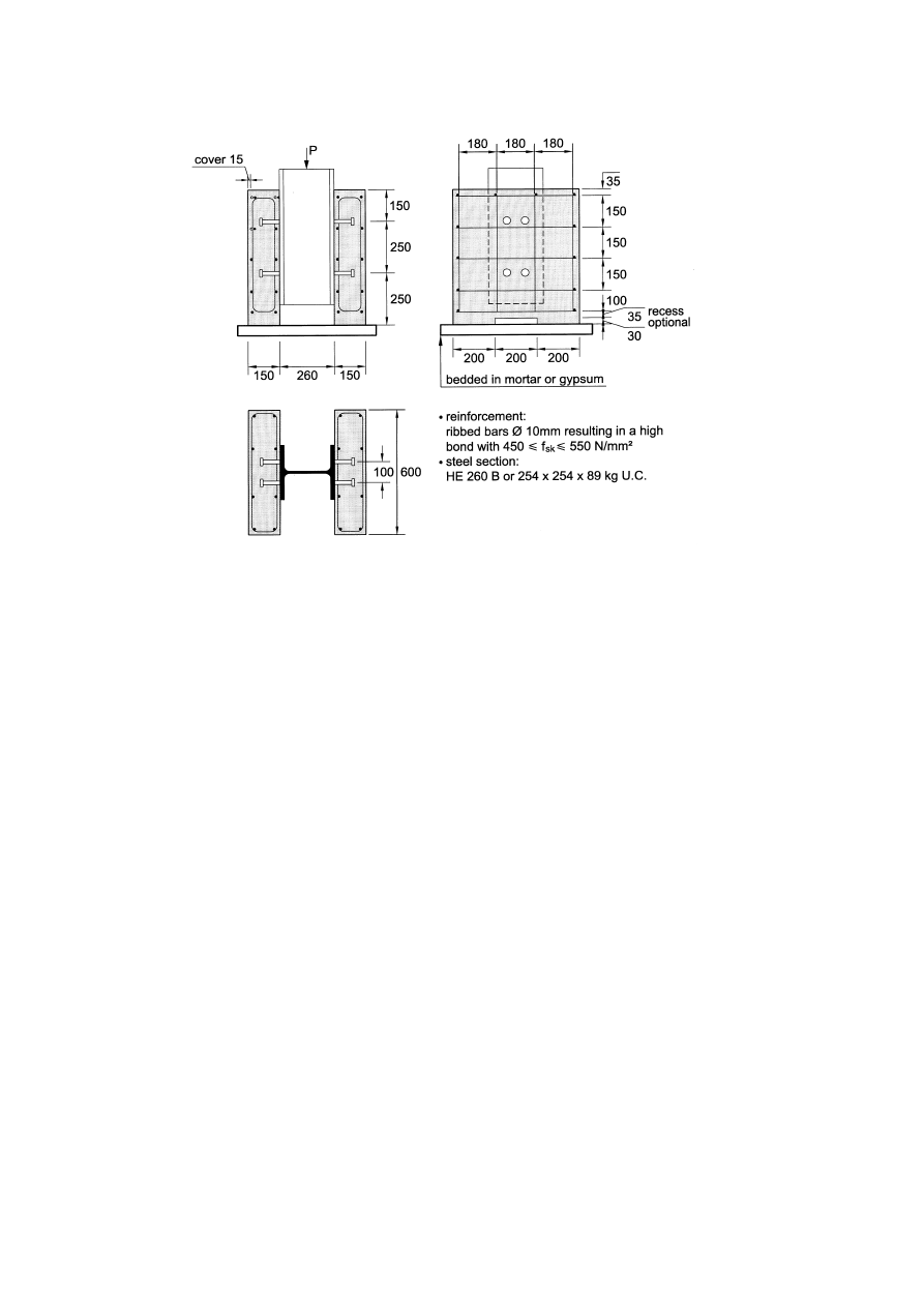
EN 1994-1-1:2004 (E)
109
Figure B.1 : Test specimen for standard push test
B.2.3 Preparation of specimens
(1) Each of both concrete slabs should be cast in the horizontal position, as is done for composite
beams in practice.
(2) Bond at the interface between flanges of the steel beam and the concrete should be prevented by
greasing the flange or by other suitable means.
(3) The push specimens should be air-cured.
(4) For each mix a minimum of four concrete specimens (cylinders or cubes) for the determination
of the cylinder strength should be prepared at the time of casting the push specimens. These
concrete specimens should be cured alongside the push specimens. The concrete strength
f
cm
should
be taken as the mean value.
(5) The compressive strength
f
cm
of the concrete at the time of testing should be 70%
± 10% of the
specified strength of the concrete
f
ck
of the beams for which the test is designed. This requirement
can be met by using concrete of the specified grade, but testing earlier than 28 days after casting of
the specimens.
(6) The yield strength, the tensile strength and the maximum elongation of a representative sample
of the shear connector material should be determined.
(7) If profiled steel sheeting is used for the slabs, the tensile strength and the yield strength of the
profiled steel sheet should be obtained from coupon tests on specimens cut from the sheets as used
in the push tests.

EN 1994-1-1: 2004 (E)
110
B.2.4 Testing procedure
(1) The load should first be applied in increments up to 40% of the expected failure load and then
cycled 25 times between 5% and 40% of the expected failure load.
(2) Subsequent load increments should then be imposed such that failure does not occur in less than
15 minutes.
(3) The longitudinal slip between each concrete slab and the steel section should be measured
continuously during loading or at each load increment. The slip should be measured at least until
the load has dropped to 20% below the maximum load.
(4) As close as possible to each group of connectors, the transverse separation between the steel
section and each slab should be measured.
B.2.5 Test
evaluation
(1) If three tests on nominally identical specimens are carried out and the deviation of any
individual test result from the mean value obtained from all tests does not exceed 10%, the design
resistance may be determined as follows:
– the
characteristic
resistance
P
Rk
should be taken as the minimum failure load (divided
by the number of connectors) reduced by 10%;
–
the design resistance
P
Rd
should be calculated from:
V
Rk
V
Rk
ut
u
Rd
γ
γ
P
P
f
f
P
≤
=
(B.1)
where:
f
u
is the minimum specified ultimate strength of the connector material;
f
ut
is the actual ultimate strength of the connector material in the test specimen; and
γ
V
is the partial safety factor for shear connection.
NOTE: The value for
γ
V
may be given in the National Annex. The recommended value for
γ
V
is 1,25.
(2) If the deviation from the mean exceeds 10%, at least three more tests of the same kind should be
made. The test evaluation should then be carried out in accordance with EN 1990, Annex D.
(3) Where the connector is composed of two separate elements, one to resist longitudinal shear and
the other to resist forces tending to separate the slab from the steel beam, the ties which resist
separation shall be sufficiently stiff and strong so that separation in push tests, measured when the
connectors are subjected to 80 % of their ultimate load, is less than half of the longitudinal
movement of the slab relative to the beam.
(4) The slip capacity of a specimen
δ
u
should be taken as the maximum slip measured at the
characteristic load level, as shown in Figure B.2. The characteristic slip capacity
δ
uk
should be taken
as the minimum test value of
δ
u
reduced by 10% or determined by statistical evaluation from all the
test results. In the latter case, the characteristic slip capacity should be determined in accordance
with EN 1990, Annex D.
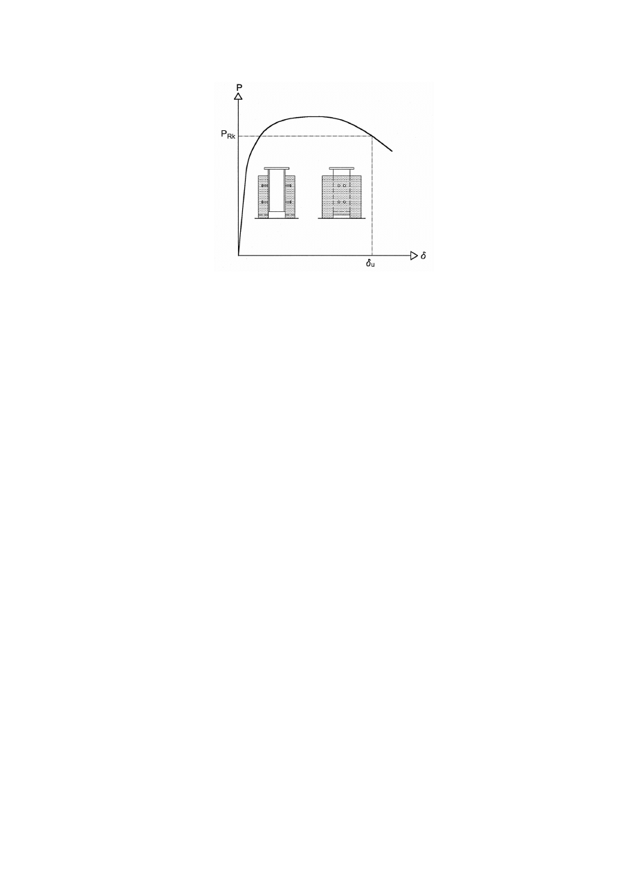
EN 1994-1-1:2004 (E)
111
Figure B.2 : Determination of slip capacity
δ
u
B.3 Testing of composite floor slabs
B.3.1 General
(1) Tests according to this section should be used for the determination of the factors
m and k or the
value of
τ
u,Rd
to be used for the verification of the resistance to longitudinal shear as given in
Section 9.
(2) From the load-deflection curves the longitudinal shear behaviour is to be classified as brittle or
ductile. The behaviour is deemed to be ductile if it is in accordance with 9.7.3(3). Otherwise the
behaviour is classified as brittle.
(3) The variables to be investigated include the thickness and the type of steel sheeting, the steel
grade, the coating of the steel sheet, the density and grade of concrete, the slab thickness and the
shear span length
L
s
.
(4) To reduce the number of tests as required for a complete investigation, the results obtained from
a test series may be used also for other values of variables as follows:
– for thickness of the steel sheeting
t larger than tested;
– for concrete with specified strength
f
ck
not less than 0.8
f
cm
, where
f
cm
is the mean value of the
concrete strength in the tests;
– for steel sheeting having a yield strength
f
yp
not less than 0.8
f
ypm
, where
f
ypm
is the mean value
of the yield strength in the tests.
B.3.2 Testing
arrangement
(1) Tests should be carried out on simply supported slabs.
(2) The test set-up should be as shown in Figure B.3 or equivalent.
(3) Two equal concentrated line loads, placed symmetrically at
L/4 and 3L/4 on the span, should be
applied to the specimen.
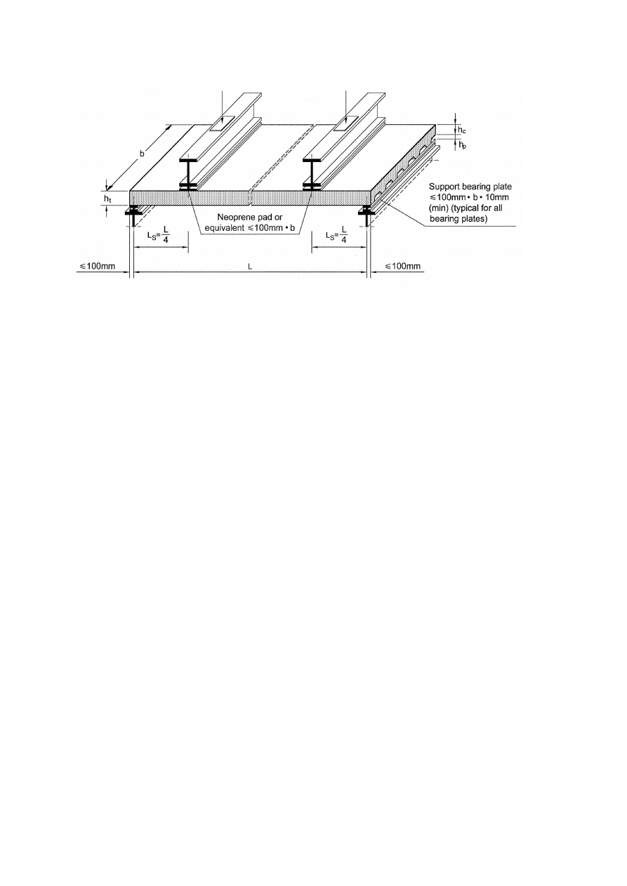
EN 1994-1-1: 2004 (E)
112
Figure B.3 : Test set-up
(4) The distance between the centre line of the supports and the end of the slab should not exceed
100 mm.
(5) The width of the bearing plates and the line loads should not exceed 100 mm.
(6) When the tests are used to determine
m and k factors, for each variable to be investigated two
groups of three tests (indicated in Figure B.4 by regions A and B) or three groups of two tests
should be performed. For specimens in region A, the shear span should be as long as possible while
still providing failure in longitudinal shear and for specimens in region B as short as possible while
still providing failure in longitudinal shear, but not less than 3
h
t
in length.
(7) When the tests are used to determine
τ
u,Rd
for each type of steel sheet or coating not less than
four tests should be carried out on specimens of same thickness
h
t
without additional reinforcement
or end anchorage. In a group of three tests the shear span should be as long as possible while still
providing failure in longitudinal shear and in the remaining one test as short as possible while still
providing failure in longitudinal shear, but not less than 3
h
t
in length. The one test with short shear
span is only used for classifying the behaviour in accordance with B.3.1(2).
B.3.3 Preparation
of
specimens
(1) The surface of the profiled steel sheet shall be in the 'as-rolled' condition, no attempt being made
to improve the bond by degreasing the surface.
(2) The shape and embossment of the profiled sheet should accurately represent the sheets to be
used in practice. The measured spacing and depth of the embossments shall not deviate from the
nominal values by more than 5% and 10% respectively.
(3) In the tension zone of the slabs crack inducers should be placed across the full width of the test
slab under the applied loads. The crack inducers should extend at least to the depth of the sheeting.
Crack inducers are placed to better define the shear span length,
Ls and to eliminate the tensile
strength of concrete.

EN 1994-1-1:2004 (E)
113
(4) It is permitted to restrain exterior webs of the deck so that they act as they would act in wider
slabs.
(5) The width
b of test slabs should not be less than three times the overall depth, 600mm and the
cover width of the profiled sheet.
(6) Specimens should be cast in the fully supported condition. This is the most unfavourable
situation for the shear bond mode of failure.
(7) Mesh reinforcement may be placed in the slab, for example to reinforce the slab during
transportation, against shrinkage, etc. If placed it must be located such that it acts in compression
under sagging moment.
(8) The concrete for all specimens in a series to investigate one variable should be of the same mix
and cured under the same conditions.
(9) For each group of slabs that will be tested within 48 hours, a minimum of four concrete
specimens, for the determination of the cylinder or cube strength, should be prepared at the time of
casting the test slabs. The concrete strength
f
cm
of each group should be taken as the mean value,
when the deviation of each specimen from the mean value does not exceed 10%. When the
deviation of the compressive strength from the mean value exceeds 10%, the concrete strength
should be taken as the maximum observed value.
(10) The tensile strength and yield strength of the profiled steel sheet should be obtained from
coupon tests on specimens cut from each of the sheets used to form the test slabs.
B.3.4
Test loading procedure
(1) The test loading procedure is intended to represent loading applied over a period of time. It is in
two parts consisting of an initial test, where the slab is subjected to cyclic loading; this is followed
by a subsequent test, where the slab is loaded to failure under an increasing load.
(2) If two groups of three tests are used, one of the three test specimens in each group may be
subjected to just the static test without cyclic loading in order to determine the level of the cyclic
load for the other two.
(3) Initial test: the slab should be subjected to an imposed cyclic load, which varies between a lower
value not greater than 0.2
W
t
and an upper value not less than 0.6
W
t
, where
W
t
is the measured
failure load of the preliminary static test according (2).
(4) The loading should be applied for 5000 cycles in a time not less than 3 hours.
(5) Subsequent test: on completion of the initial test, the slab should be subjected to a static test
where the imposed load is increased progressively, such that failure does not occur in less than 1
hour. The failure load
W
t
is the maximum load imposed on the slab at failure plus the weight of the
composite slab and spreader beams.
(6) In the subsequent test the load may be applied either as force-controlled or deflection-controlled.
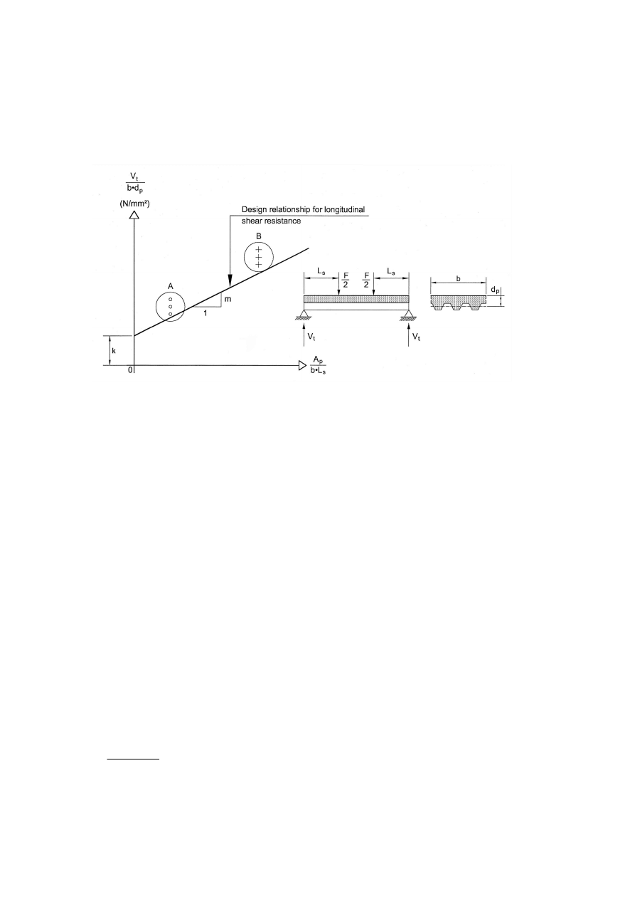
EN 1994-1-1: 2004 (E)
114
B.3.5
Determination of design values for m and k
(1) If the behaviour is ductile, see 9.7.3(3), the representative experimental shear force
V
t
should be
taken as 0.5 times the value of the failure load
W
t
as defined in B.3.4. If the behaviour is brittle this
value shall be reduced, using a factor 0.8.
NOTE: b, d
p
and L
s
are in mm, A
p
is in mm
2
, V
t
is in N.
Figure B.4 : Evaluation of test results
(2) From all the test values of
V
t
the characteristic shear strength should be calculated as the 5%
fractile by using an appropriate statistical model and drawn as a characteristic linear regression line,
as shown in Figure B.4.
(3) If two groups of three tests are used and the deviation of any individual test result in a group
from the mean of the group does not exceed 10%, the design relationship may be determined in
accordance with Annex D of EN 1990 or as follows:
From each group the characteristic value is deemed to be the one obtained by taking the
minimum value of the group reduced by 10%. The design relationship is formed by the straight
line through these characteristic values for groups A and B.
B.3.6
Determination of the design values for
τ
u,Rd
(1) The partial interaction diagram as shown in Figure B.5 should be determined using the
measured dimensions and strengths of the concrete and the steel sheet. For the concrete strength the
mean value
f
cm
of a group as specified in B.3.3(9) may be used.
(2) From the maximum applied loads, the bending moment
M at the cross-section under the point
load due to the applied load, dead weight of the slab and spreader beams should be determined. The
path A --> B --> C in Figure B.5 then gives a value
η
for each test, and a value
τ
u
from:
(
)
o
s
cf
u
L
L
b
N
+
=
η
τ
(B.2)
where:
L
o
is the length of the overhang.
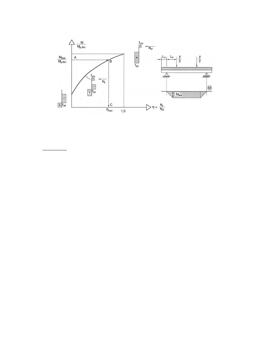
EN 1994-1-1:2004 (E)
115
Figure B.5 : Determination of the degree of shear connection from M
test
(3) If in design the additional longitudinal shear resistance caused by the support reaction is taken
into account in accordance with 9.7.3(9),
τ
u
should be determined from:
(
)
o
s
t
cf
L
L
b
V
N
u
+
−
=
µ
η
τ
(B.3)
where:
µ
is the default value of the friction coefficient to be taken as 0.5;
V
t
is the support reaction under the ultimate test load.
(4) The characteristic shear strength
τ
u,Rk
should be calculated from the test values as the 5% fractile
using an appropriate statistical model in accordance with EN 1990, Annex D.
(5) The design shear strength
τ
u,Rd
is the characteristic strength
τ
u,Rk
divided by the partial safety
coefficient
γ
VS
.
NOTE: The value for
γ
VS
may be given in the National Annex. The recommended value for
γ
VS
is 1,25.

EN 1994-1-1: 2004 (E)
116
Annex C (Informative)
Shrinkage of concrete for composite structures for buildings
(1) Unless accurate control of the profile during execution is essential, or where shrinkage is
expected to take exceptional values, the nominal value of the total final free shrinkage strain may be
taken as follows in calculations for the effects of shrinkage:
– in dry environments (whether outside or within buildings but excluding concrete- filled
members):
325 x 10
-6
for normal concrete
500 x 10
-6
for lightweight concrete;
– in other environments and in filled members:
200 x 10
-6
for normal concrete
300 x 10
-6
for lightweight concrete.

EN 1994-1-1:2004 (E)
117
Bibliography
EN 1991-1-5:
Actions on structures: Thermal actions-to be published.
EN 1991-1-6:
Actions on structures: Actions during execution-to be published.
EN 13670:
Requirements for the execution of concrete structures-to be published.
EN ISO 13918: 1998 Welding-Studs and ceramic ferrules for arc stud welding (ISO 13918:1998).
EN ISO 14555: 1998 Welding-Arc stud welding of metallic materials (ISO 14555:1998).
Wyszukiwarka
Podobne podstrony:
Eurocode 1 Part 1,6 prEN 1991 1 6 2004
Eurocode 2 Part 1,2 prEN 1992 1 2 2004
Eurocode 2 Part 3 prEN 1992 3 2004
Eurocode 1 Part 1,4 prEN 1991 1 4 2004
Eurocode 3 Part 1,5 prEN 1993 1 5 2004 (Juin 2004)
Eurocode 3 Part 5 prEN 1993 5 (2004 Jul)
Eurocode 1 Part 1,6 prEN 1991 1 6 2004
Eurocode 3 Part 5 prEN 1993 5 (2004 Jul)
Eurocode 3 Part 2 (prEN 1993 2 March 2004)
Eurocode 4 Part 2 DDENV 1994 2 1997
Eurocode 8 Part 1 prEN 1998 1 (12 2003)
Eurocode 1 Part 2 prEN 1991 2 2002
Eurocode 1 Part 1,2 prEN 1991 1 2 2002
Eurocode 1 Part 1,1 prEN 1991 1 1 2001
Eurocode 1 Part 1,3 prEN 1991 1 3 2003
więcej podobnych podstron