3
Steel Design Guide
Serviceability Design
Considerations
Second Edition
for Steel Buildings
cover DG3 revise.qxd 4/27/2004 8:58 AM Page 3

3
Steel Design Guide
Serviceability Design
Considerations
MICHAEL WEST AND JAMES FISHER
Computerized Structural Design, Inc.
Milwaukee, Wisconsin
with contributions from
LAWRENCE G. GRIFFIS
Walter P. Moore and Associates
Austin, Texas
A M E R I C A N I N S T I T U T E O F S T E E L C O N S T RU C T I O N , I N C.
for Steel Buildings
Second Edition

Copyright © 2003
by
American Institute of Steel Construction, Inc.
All rights reserved. This book or any part thereof
must not be reproduced in any form without the
written permission of the publisher.
The information presented in this publication has been prepared in accordance with recognized
engineering principles and is for general information only. While it is believed to be accurate,
this information should not be used or relied upon for any specific application without com-
petent professional examination and verification of its accuracy, suitability, and applicability
by a licensed professional engineer, designer, or architect. The publication of the material con-
tained herein is not intended as a representation or warranty on the part of the American
Institute of Steel Construction or of any other person named herein, that this information is suit-
able for any general or particular use or of freedom from infringement of any patent or patents.
Anyone making use of this information assumes all liability arising from such use.
Caution must be exercised when relying upon other specifications and codes developed by other
bodies and incorporated by reference herein since such material may be modified or amended
from time to time subsequent to the printing of this edition. The Institute bears no responsi-
bility for such material other than to refer to it and incorporate it by reference at the time of the
initial publication of this edition.
Printed in the United States of America
First Printing: March 2004

v
Preface
Acknowledgements
This Design Guide is the second edition of AISC Design
Guide 3, which was originally titled Serviceability Design
Considerations for Low-Rise Buildings. The new title Ser-
viceability Design Considerations for Steel Buildings
reflects the addition of information on tall buildings and the
following more general information:
1. A review of steel building types, occupancies and ser-
viceability design considerations related to each, as
applicable.
2. Revision to current editions of references.
3. Information on ponding for roof design.
4. Information on floors, including discussion regarding
cambering beams and how deflection issues relate to the
construction of concrete slabs.
5. Revision of floor vibration information to follow AISC
Design Guide 11, Floor Vibrations Due to Human Activity
(Murray and others, 1997).
AISC would also like to thank the following people for
assistance in the review of this Design Guide. Their com-
ments and suggestions have been invaluable.
Todd Alwood
Harry A. Cole
Charles J. Carter
Cynthia J. Duncan
Tom Ferrell
Louis F. Geschwindner
John L. Harris
Christopher M. Hewitt
Lawrence Kloiber
Jay W. Larson
Roberto Leon
William Liddy
Ronald L. Meng
Charles R. Page
Davis Parsons
David T. Ricker
Victor Shneur
William T. Segui
Eldon Tipping
The authors wish to thank the Metal Building Manufactur-
ers Association for its joint support with AISC in the prepa-
ration of the first edition of this Guide.


vii
Table of Contents
Chapter 1
Introduction ......................................................................1
Serviceability Requirements in the
AISC Specification ....................................................1
Storage/Warehouses ......................................................3
Manufacturing................................................................3
Heavy Industrial/Mill Buildings ....................................3
Mercantile/Shopping Malls............................................4
Health Care and Laboratory Facilities ..........................4
Educational ....................................................................4
Office Buildings ............................................................4
Parking Structures..........................................................5
Residential/Apartments/Hotels ......................................5
Assembly/Arenas ..........................................................5
Seismic Applications......................................................5
Chapter 2
Design Considerations Relative to Roofing ....................7
Ponding Stability............................................................7
Roofing ..........................................................................9
Membrane Roofs............................................................9
Metal Roofs..................................................................11
Chapter 3
Design Considerations Relative to Skylights................13
Chapter 4
Design Considerations Relative to Cladding,
Frame Deformation, and Drift ......................................15
Cladding-Structure Interaction ....................................15
Foundation-Supported Cladding for Gravity Loads ....15
Frame-Supported Cladding at Columns ......................18
Frame-Supported Cladding for Gravity
Loads Along Spandrels ............................................19
Special Considerations for Tall Buildings ..................19
Chapter 5
Design Considerations Relative to Interior
Partitions and Ceilings ..................................................21
Support Deflection ......................................................21
Flat and Level Floors ..................................................21
Specifying Camber and Camber Tolerances................22
Maintaining Floor Elevation ........................................23
Chapter 6
Design Considerations Relative to
Vibration/Acceleration ..................................................25
Human Response to Vibration ....................................25
Machines and Vibration ..............................................25
Tall Building Acceleration—Motion Perception ........25
Chapter 7
Design Considerations Relative to Equipment ............29
Elevators ......................................................................29
Conveyors ....................................................................29
Cranes ..........................................................................29
Mechanical Equipment ................................................30
References........................................................................33
Appendix
Summary of Serviceability Considerations..................37

DESIGN GUIDE 3, 2ND EDITION / SERVICEABILITY DESIGN CONSIDERATIONS FOR STEEL BUILDINGS / 1
Serviceability is defined in the AISC Specification as “a
state in which the function of a building, its appearance,
maintainability, durability, and comfort of its occupants are
preserved under normal usage”. Although serviceability
issues have always been a design consideration, changes in
codes and materials have added importance to these mat-
ters.
The shift to a limit-states basis for design is one example.
Since 1986, both the AISC LRFD and AISC ASD Specifi-
cations have been based upon the limit-states design
approach in which two categories of limit states are recog-
nized: strength limit states and serviceability limit states.
Strength limit states control the safety of the structure and
must be met. Serviceability limit states define the functional
performance of the structure and should be met.
The distinction between the two categories centers on the
consequences of exceeding the limit state. The conse-
quences of exceeding a strength limit may be buckling,
instability, yielding, fracture, etc. These consequences are
the direct response of the structure or element to load. In
general, serviceability issues are different in that they
involve the response of people and objects to the behavior
of the structure under load. For example, the occupants may
feel uncomfortable if there are unacceptable deformations,
drifts, or vibrations.
Whether or not a structure or element has passed a limit
state is a matter of judgment. In the case of strength limits,
the judgment is technical and the rules are established by
building codes and design specifications. In the case of ser-
viceability limits, the judgments are frequently non-techni-
cal. They involve the perceptions and expectations of
building owners and occupants. Serviceability limits have,
in general, not been codified, in part because the appropri-
ate or desirable limits often vary from application to appli-
cation. As such, they are more a part of the contractual
agreements with the owner than life-safety related. Thus, it
is proper that they remain a matter of contractual agreement
and not specified in the building codes.
In a perfect world the distinction between strength and
serviceability would disappear. There would be no prob-
lems or failures of any kind. In the real world all design
methods are based upon a finite, but very small probability
of exceedance. Because of the non-catastrophic conse-
quences of exceeding a serviceability limit state, a higher
probability of exceedance is allowed by current practice
than for strength limit states.
The foregoing is not intended to say that serviceability
concerns are unimportant. In fact, the opposite is true. By
having few codified standards, the designer is left to resolve
these issues in consultation with the owner to determine the
appropriate or desired requirements.
Serviceability problems cost more money to correct than
would be spent preventing the problem in the design phase.
Perhaps serviceability discussions with the owner should
address the trade-off between the initial cost of the potential
level of design vs. the potential mitigation costs associated
with a more relaxed design. Such a comparison is only pos-
sible because serviceability events are by definition not
safety related. The Metal Building Manufactures Associa-
tion (MBMA) in its Common Industry Practices (MBMA,
2002) states that the customer or his or her agent must iden-
tify for the metal building engineer any and all criteria so
that the metal building can be designed to be “suitable for
its specific conditions of use and compatible with other
materials used in the Metal Building System.” Nevertheless,
it also points out the requirement for the active involvement
of the customer in the design stage of a structure and the
need for informed discussion of standards and levels of
building performance. Likewise the AISC Code of Standard
Practice (AISC, 2000) states that in those instances where
the fabricator has both design and fabrication responsibility,
the owner must provide the “performance criteria for the
structural steel frame.”
Numerous serviceability design criteria exist, but they are
spread diversely through codes, journal articles, technical
committee reports, manufacturers’ literature, office stan-
dards and the preferences of individual engineers. This
Design Guide gathers these criteria for use in establishing
serviceability design criteria for a project.
Serviceability Requirements in the AISC Specification
The LRFD Specification (AISC, 1999) lists five topics that
relate to serviceability concerns. They are:
1. camber
2. expansion and contraction
3. deflections, vibrations, and drift
4. connection slip
5. corrosion
Camber
Camber may or may not be a solution to a serviceability
issue, and the authors have attempted to identify appropri-
Chapter 1
Introduction

2 / DESIGN GUIDE 3, 2ND EDITION / SERVICEABILITY DESIGN CONSIDERATIONS FOR STEEL BUILDINGS
ate and inappropriate use of camber in this Design Guide. In
most instances, the amount of total movement is of concern
rather than the relative movement from the specified floor
elevation, in which case camber is not an appropriate solu-
tion. There are, however, situations where camber is appro-
priate, such as in places where it is possible to sight down
the under side of exposed framing.
Expansion and Contraction
Expansion and contraction is discussed to a limited extent.
The goal of this Design Guide is to discuss those aspects of
primary and secondary steel framing behavior as they
impact non-structural building components. For many types
of low-rise commercial and light industrial projects, expan-
sion and contraction in the limited context given above are
rarely an issue. This does not mean that the topic of expan-
sion and contraction is unimportant and, of course, the
opposite is true. For large and/or tall structures, careful con-
sideration is required to accommodate absolute and relative
expansion and contraction of the framing and the non-struc-
tural components.
Connection Slip
Connection slip has not been addressed explicitly in this
Design Guide. However, it is the authors’ intent that the var-
ious drift and deflection limits include the movements due
to connection slip. Where connection slip, or especially the
effect of accumulated connection slip in addition to flexural
and/or axial deformations, will produce movements in
excess of the recommended guidelines, slip-critical joints
should be considered. Slip-critical joints are also required in
specific instances enumerated in Section 5 of the Specifica-
tion for Structural Joints Using ASTM A325 or ASTM A490
Bolts (RCSC, 2000). It should be noted that joints made
with snug-tightened or pretensioned bolts in standard holes
will not generally result in serviceability problems for indi-
vidual members or low-rise frames. Careful consideration
should be given to other situations.
Corrosion
Corrosion, if left unattended, can lead to impairment of
structural capacity. Corrosion is also a serviceability con-
cern as it relates to the performance of non-structural ele-
ments and must be addressed by proper detailing and
maintenance. The primary concerns are the control or elim-
ination of staining of architectural surfaces and prevention
of rust formation, especially inside assemblies where it can
induce stresses due to the expansive nature of the oxidation
process. Again, the solutions are proper detailing and main-
tenance.
Serviceability Requirements in ASCE 7
ASCE 7-02, Minimum Design Loads for Buildings and
Other Structures (ASCE, 2002) addresses serviceability in
paragraph 1.3.2 Serviceability as follows:
“Structural systems, and members thereof, shall be
designed to have adequate stiffness to limit deflec-
tions, lateral drift, vibration, or any other deforma-
tions that adversely affect the intended use and
performance of buildings and other structures.”
ASCE 7-02 provides an appendix with commentary enti-
tled Serviceability Considerations. While this appendix is
non-mandatory, it does draw attention to the need to con-
sider five topic areas related to serviceability in the design
of structures:
• deflection, vibration, and drift
• design for long-term deflection
• camber
• expansion and contraction
• durability
The ASCE 7 appendix introduction notes that “service-
ability shall be checked using appropriate loads for the limit
state being considered.” The commentary to the Appendix
provides some suggestions with regard to loads and load
combinations. For example, two load combinations are sug-
gested for vertical deflections of framing members:
D + L
D + 0.5S
These are recommended for limit states “involving visu-
ally objectionable deformations, repairable cracking or
other damage to interior finishes, and other short term
effects.” For serviceability limit states “involving creep, set-
tlement, or other similar long-term or permanent effects,”
the suggested load combination is:
D + 0.5L
With regard to lateral drift, the commentary cites the
common interstory drift limits of L/600 to L/400. The com-
mentary also notes that an absolute interstory drift limit of
3
/
8
in. (10 mm) may often be appropriate to prevent damage
to non-structural elements. This absolute limit may be
relaxed if there is appropriate detailing in the non-structural
elements to accommodate greater drift. The commentary
provides the following load combination for checking
short-term effects:
D + 0.5L + 0.7W
The reader is encouraged to refer to the appendix commen-

DESIGN GUIDE 3, 2ND EDITION / SERVICEABILITY DESIGN CONSIDERATIONS FOR STEEL BUILDINGS / 3
tary, which provides additional insights into the issue of ser-
viceability and an extensive list of references.
This Guide will address the following serviceability
design criteria:
1. roofing
2. skylights
3. cladding
4. interior partitions and ceilings
5. vibrations
6. equipment
Most of these criteria limit relative and absolute deflec-
tion and, in the case of vibrations, place limits on the range
of response and controls for the physical characteristics of
structures and elements. Additionally, the presentation and
discussion of a consistent loading and analysis approach is
essential to these criteria. Without these three elements
(load, analysis approach, and serviceability limit) a service-
ability design criterion is useless.
This Design Guide provides serviceability design criteria
are for selected applications. Source material has been doc-
umented wherever possible. Many of the design criteria are
based upon the authors’ own judgment and rules of thumb
from their own experience. It should be noted that when
applicable building codes mandate specific deflection limits
the code requirements supersede the recommendations of
this Design Guide.
Structures framed in structural steel accommodate
numerous occupancies and building types. The following
discussion addresses ten occupancy types and the specific
serviceability design considerations associated with these
occupancies.
Storage/Warehouses
Most modern storage facilities, unlike those of previous
eras, are single story buildings. As such, modern storage
occupancies usually enclose large unobstructed areas under
a roof. The significant serviceability design considerations
are:
• roof slope and drainage
• ponding stability
• roof deflection
• wall support and girt deflection
• frame drift
• expansion joints
Manufacturing
Like Storage/Warehouse facilities, modern manufacturing
facilities are large single story structures, which may
include extensive mezzanines. The most significant service-
ability design considerations for this occupancy type are:
• roof slope and drainage
• ponding stability
• roof deflection
• wall support and girt deflection
• frame drift
• expansion joints
• vibration in mezzanine areas
• suspended equipment
• crane operation
• corrosion
• equipment vibration
In addition to the serviceability considerations provided
in this Guide, the reader is referred to AISC Design Guide 7,
Industrial Buildings: Roofs to Column Anchorage (AISC,
2004) for a useful discussion on manufacturing facilities.
Heavy Industrial/Mill Buildings
Heavy industrial and mill construction has many of the
same serviceability considerations as Manufacturing. Addi-
tionally, care must be taken to ensure the proper operation
and performance of the cranes. AISC Design Guide 7,
Industrial Buildings: Roofs to Column Anchorage (AISC, 2004)
is worthwhile reading on this subject. The significant ser-
viceability design considerations are:
• crane operation
• roof slope and drainage
• ponding stability
• roof deflection
• wall support and girt deflection
• frame drift
• expansion joints

4 / DESIGN GUIDE 3, 2ND EDITION / SERVICEABILITY DESIGN CONSIDERATIONS FOR STEEL BUILDINGS
• vibration of floors
• concreting of floors
• suspended equipment
• elevator operation
• skylights
Educational
Schools and other academic buildings are constructed as
both single and multi-story structures. Typical serviceabil-
ity considerations for floors, roofs and walls apply to all
such structures. Structures in schools with swimming pools
must be protected against a potentially corrosive environ-
ment. Schools with physical education facilities on upper
levels must consider the impact of floor vibrations on the
structure, especially those due to rhythmic excitation.
Lenzen (1966), cites the case of a school in which floor
vibrations were not perceptible when the teacher and stu-
dents were present, but vibration was deemed to be annoy-
ing when the classroom was empty except for teachers
working after classes. The significant serviceability design
considerations for educational occupancies are:
• roof slope and drainage
• ponding stability
• roof deflection
• curtain wall/spandrel deflection
• frame drift
• expansion joints
• floor deflection
• vibration of floors
• concreting of floors
• skylights
• corrosion
Office Buildings
Office buildings are constructed in all heights from single-
story buildings to high-rise towers. The relationship of the
building frame to the curtain wall is important, as are frame
drift and floor deflection. Floor vibration can be an issue.
Mercantile/Shopping Malls
Mercantile structures are frequently large one and two story
structures sharing some of the same serviceability design
considerations as Storage/Warehouse occupancies. With
large areas of roof drainage, roof deflections and expansion
joints require special attention. As AISC Design Guide 11,
Floor Vibrations Due to Human Activity (AISC, 1997)
points out, objectionable vibrations have been observed in
the second floor levels of these types of structures. Objec-
tionable floor vibrations can result from a lack of damping
in open pedestrian areas and walkways. This is discussed in
detail in Design Guide 11. The significant serviceability
design considerations for mercantile occupancies are:
• roof slope and drainage
• ponding stability
• roof deflection
• frame drift
• expansion joints
• floor vibration
• skylights
• corrosion in winter garden and large fountain areas
Health Care and Laboratory Facilities
Although hospitals and clinics are generally multi-story
structures, they can be constructed as single-story facilities.
The performance of the floor structures is of significant
concern, and special attention should be given to the effect
of floor vibration on sensitive laboratory equipment. The
relationship between the frame and the curtain wall is
another important design consideration, as is the perform-
ance and operation of traction elevators. The significant ser-
viceability design considerations for health care
occupancies are:
• roof slope and drainage
• ponding stability
• roof deflection
• curtain wall/spandrel deflection
• frame drift
• expansion joints
• floor deflection

DESIGN GUIDE 3, 2ND EDITION / SERVICEABILITY DESIGN CONSIDERATIONS FOR STEEL BUILDINGS / 5
Elevator operation is also a significant concern. The major
serviceability considerations for office occupancies are:
• roof slope and drainage
• ponding stability
• roof deflection
• curtain wall/spandrel deflection
• frame drift
• perception of wind-induced acceleration
• expansion joints
• floor deflection
• vibration of floors
• concreting of floors
• suspended equipment
• elevator operation
• skylights
Parking Structures
Structural steel-framed parking structures are frequently
open structures, which exposes the framing. Protection of
the structural steel and connections from corrosion and
good drainage are significant concerns. More detailed infor-
mation on the design of steel-framed open-deck parking
structures is available in AISC Design Guide 18, Open-
Deck, Steel-Framed Parking Structures (Churches, and oth-
ers 2003). The significant serviceability design
considerations for parking structures are:
• deck slope and drainage
• expansion joints
• concreting of floors
• corrosion
Residential/Apartments/Hotels
Residential occupancies that are steel framed are commonly
mid- to high-rise structures. Frequently the taller of these
structures are mixed use buildings with portions of the
space devoted to office and retail occupancies. Most, if not
all, of the serviceability design considerations for office
occupancies apply to residential occupancies. These are:
• roof slope and drainage
• ponding stability
• roof deflection
• curtain wall/spandrel deflection
• frame drift
• perception of wind-induced acceleration
• expansion joints
• floor deflection
• vibration of floors
• concreting of floors
• suspended equipment
• elevator operation
• skylights
• corrosion in chlorine-disinfected swimming pools
Assembly/Arenas
Assembly occupancies are not discussed extensively in this
Design Guide. These buildings are by nature unique, one-
of-a-kind structures with large open spans. The accommo-
dation of large deflections and the associated cambers and
thermal movements are critical aspects of the design. Addi-
tionally, the potential for rhythmic excitation of the struc-
ture by the crowd must be considered.
Seismic Applications
It should be noted that this Design Guide does not provide
guidance on serviceability limit states exceeded due to the
deformations and interstory drifts of a structural frame sub-
jected to seismic loading. Such requirements are explicitly
included in the building code and the reader is referred
there.

DESIGN GUIDE 3, 2ND EDITION / SERVICEABILITY DESIGN CONSIDERATIONS FOR STEEL BUILDINGS / 7
Roof serviceability largely relates to the structure's role in
maintaining the integrity of the roofing membrane and the
drainage system. Although ponding relates to both the
strength and stiffness of the roof structure, ponding stability
is ultimately a strength design consideration; see AISC
Specification Section K2 (LRFD, 1999; ASD 1989).
Because of the importance of ponding stability as a design
issue, and because ponding instability is a function of load
and deflection, the following discussion of the topic is
included in this design guide.
Ponding Stability
The AISC Specification provides that unless a roof surface
is provided with sufficient slope towards points of free
drainage, or adequate individual drains to prevent the accu-
mulation of rain water, the roof system must be investigated
to ensure adequate strength and stability under ponding
conditions. The ponding investigation must be performed
by the specifying engineer or architect. ASCE 7-02 estab-
lishes adequate slope to drain as
1
/
4
-in. per ft in Section 8.4.
Additional information is provided in the Steel Joist Insti-
tute Technical Digest No 3, Structural Design of Steel Joist
Roofs to Resist Ponding (SJI, 1971).
Ponding as a structural design phenomenon is of concern
for two reasons:
1. The loading is water, which can fill and conform to a
deflected roof surface.
2. The source of load (water) is uncontrollable, i.e. rain is a
natural hazard.
When water can accumulate on a structural system due to
impoundment or restriction in drainage, ponding must be
checked. Reasons for the accumulation can be:
1. Dead load deflections of members in roofs designed to
be flat.
2. Deflections of members, which places points in their
spans below their end points.
3. Deflections of bays supporting mechanical units.
4. Members installed with inverted cambers.
5. Blocked roof drains.
6. Parapets without scuppers.
7. Parapets with blocked scuppers.
8. Intentional impoundment of water as part of a con-
trolled-flow roof drain design.
9. Low-slope roofs, which allow water to accumulate due
to the hydraulic gradient.
Ponding rainwater causes the deflection of a roof system,
which in turn increases the volumetric capacity of the roof.
Additional water is retained which in turn causes additional
deflection and volumetric capacity in an iterative process.
The purpose of a ponding check is to ensure that conver-
gence occurs, i.e. that an equilibrium state is reached for the
incremental loading and the incremental deflection. Also,
stress at equilibrium must not be excessive.
The AISC Specification in Section K2 gives limits on
framing stiffness that provide a stable roof system. They
are:
C
p
+ 0.9C
s
≤ 0.25
I
d
≥ 25(S
4
)10
-6
where,
C
p
=(32L
s
L
p
4
) / (10
7
I
p
)
C
s
= (32SL
s
4
) / (10
7
I
s
)
L
p
= length of primary members, ft
L
s
= length of secondary members, ft
S = spacing of secondary members, ft
I
p
= moment of inertia of primary members, in.
4
I
s
= moment of inertia of secondary members, in.
4
I
d
= moment of inertia of the steel deck, in.
4
per ft
Equation K2-2 is met in most buildings without the need
for increased deck stiffness. Equation K2-1, in many cases,
requires stiffer elements than would be required by loading.
In the majority of cases, roofs that do not meet equation K2-2
can be shown to conform to the bending stress limit of
0.80F
y
in the ASD Specification or F
y
in the LRFD Specifi-
cation. The relationship between the requirements of the
two specifications is discussed in “Ponding Calculations in
LRFD and ASD” (Carter and Zuo, 1999).
Appendix K of the LRFD Specification and the Com-
mentary to the ASD Specification provide a procedure to
meet the total bending stress requirement. It should be
noted that the checking of bending stresses is not required
if the stiffness controls of equations K2-1 and K2-2 are met.
This procedure is based on:
1. A calculation of the deflection due to the accumulation
of water in the deflected shape of the primary and sec-
ondary members at the initiation of ponding. These
Chapter 2
Design Considerations Relative to Roofing
(Eq. K2-1)
(Eq. K2-2)

8 / DESIGN GUIDE 3, 2ND EDITION / SERVICEABILITY DESIGN CONSIDERATIONS FOR STEEL BUILDINGS
deflected shapes are taken to be half sine waves, which
is sufficiently accurate for this calculation.
2. In LRFD a load factor of 1.2 is used for dead and rain
load per Appendix K with an implied value of
φ = 1.0
(see Carter/Zuo, 1999). In ASD a factor of safety of 1.25
for stresses due to ponding is used, which results in an
allowable stress of 0.8F
y
.
3. Behavior of the members is in the elastic range so that
deflection is directly proportional to stress.
4. Stress due to ponding is limited to F
y
(LRFD) or 0.80F
y
(ASD) minus the factored stress or stress in the members
at the initiation of ponding, depending on the specifica-
tion applied.
Thus, the method uses four variables:
U
p
, the stress index for the primary member.
U
s
, the stress index for the secondary member.
C
p
, the stiffness index for the primary member.
C
s
, the stiffness index for the secondary member.
C
p
and C
s
are as given in the Specification in Section K2.
U
p
and U
s
are given as:
(F
y
− f
o
) / f
o
(0.8F
y
− f
o
) / f
o
where f
o
is the bending stress in the member (primary or
secondary) at the initiation of ponding. In LRFD f
o
is cal-
culated using the factored load of 1.2D + 1.2R, with D = the
nominal dead load and R = the nominal rain/snow load.
Both the LRFD Specification Appendix and the ASD
Specification Commentary present two figures K2.1 and
K2.2. Figure K2.1 is used to find a maximum C
p
when U
p
and C
s
are given. Figure K2.2 is used to find a maximum C
s
when U
s
and C
p
are given. This procedure is thus a check-
ing procedure since trial sections must be chosen to estab-
lish C
p
, C
s
, U
p
, and U
s
. Figures K2.1 and K2.2 are graphs
representing combinations of stress and stiffness that con-
trol the increment of load (stress) and deflection at the ini-
tiation of ponding.
If one studies the relationships in these figures, it can be
noted that the required stiffness is inversely related to initial
stress. If the stress index associated with values of C
p
and C
s
that meet the stiffness limit of C
p
+ 0.9C
s
≤ 0.25 is plotted,
one can see that the stress index is very low, indicating that
f
o
is very near 0.9F
y
(LRFD) or 0.6F
y
(ASD). This is logical
since the system is so rigid that the ponded accumulation is
negligible. As one moves beyond the values of C
p
and C
s
that meet Equation K-2.1, it can be seen that the term (F
y
− f
o
)
(LRFD) or (0.8F
y
− f
o
) (ASD) must increase to provide for
the reduction in stiffness, e.g. the increase in C
p
and/or C
s
.
Thus it can be seen that the accurate calculation of fo is the
essential element in using this procedure.
The LRFD Appendix and the ASD Commentary states
that f
o
is “the computed bending stress in the member due to
the supported loading, neglecting the ponded effect.” The
calculations for the increment of ponded water are a func-
tion of the initial deflection and stiffness of the primary and
secondary members. The initial deflection and the initial
stress are the result of the “initial loads,” which are those
present at the “initiation of ponding.” This means that the
“initial loads” may be and will probably be different from
the design loads. The initial loads include all appropriate
dead and collateral loads, such as:
1. Weight of structural system.
2. Weight of roofing and insulation system.
3. Weight of interior finishes.
4. Weight of mechanical and electrical systems.
5. Weight of roof top mechanical systems.
The initial loads also include some or all of the superim-
posed load. The requirements of the AISC Specification and
Commentary point to the fact that the superimposed load
must actually be present at the initiation of ponding. Thus
the appropriate portion of design superimposed load is not
necessarily 100 percent of the design superimposed load.
The amount of superimposed load used is to a degree up to
the judgment of the engineer.
The most significant loading in northern regions of the
country is a prediction of the amount of snow present at the
initiation of ponding. A significant factor in all regions is a
judgment of the amount of water on the roof at the initiation
of ponding. Also, consideration must be given to the com-
bination of snow and water, where applicable. The AISC
Specification (LRFD Appendix and ASD Commentary)
demonstrate that the loading at the initiation of ponding
does not include the water that produces the stresses due to
ponding, but does include water trapped on the roof because
the roof has not been “provided with sufficient slope
towards points of free drainage or adequate individual
drains to prevent the accumulation of rain water.” Also, as
noted above, ASCE 7-02 Section 8.3 states that roofs with a
slope of at least
1
/
4
in. per ft need not be investigated for
ponding stability. However, the superimposed load at the
initiation of ponding could include water trapped by
plugged internal roof drains.
ASCE 7-02 Section 8.3 requires that “each portion of a
roof shall be designed to sustain the load of all rainwater
that will accumulate on it if the primary drainage system for

DESIGN GUIDE 3, 2ND EDITION / SERVICEABILITY DESIGN CONSIDERATIONS FOR STEEL BUILDINGS / 9
that portion is blocked plus the uniform load caused by
water that rises above the inlet of the secondary drainage
system at its design flow.” Previous model codes included
similar requirements.
The use of the weight of trapped or impounded water is
recommended in SJI Technical Digest No. 3, Structural
Design of Steel Joist Roofs to Resist Ponding Loads. This
reference also gives an approach for accounting for the
potential for snow and water in combination. It recom-
mends that “where ice and snow are the principal source of
roof live load” 50 percent of the design live load be used up
to 30 psf live load, and 100 percent of the design live load
when the design live load is 40 psf and greater.” Presumably
the percentage could be interpreted as varying linearly for
loads between 30 and 40 psf. When these values are used to
account for rain and snow, it is not necessary to add in the
weight of potential trapped water described above unless
the weight of impounded water would be greater than the
reduced design live load. Model building codes require that
roofs with a slope of less than
1
/
2
in 12 be designed for rain
on snow in accordance with ASCE 7-02 Section 1608.3.4.
ASCE 7-02 requires a rain on snow load where p
g
is 20 lb/ft
2
or less but not zero.
ASCE 7-02 requires that roofs with “controlled
drainage” must be checked for ponding instability, as deter-
mined in the provisions for “ponding instability.” When
these provisions apply, they require that “The larger of snow
load or rain load shall be used in this analysis. The primary
drainage system within an area subjected to ponding shall
be considered to be blocked in this analysis.”
Note that the earlier discussion described two-way roof
framing systems. There is a separate case where the sec-
ondary framing bears directly on walls. This case eliminates
the primary member deflection and the AISC Specification
(LRFD Appendix and ASD Commentary) procedures can
be used by reference to Figures K2.1 and K2.2 for which C
s
is calculated using the deck properties and C
p
is calculated
using the joist properties. Also the SJI Technical Digest No. 3
gives a procedure for accounting for a reduction in the accu-
mulated water weight due to camber. Logic suggests that
concept could also be applied to the two-way system.
Neither AISC nor SJI procedures address the deflected
geometry of a continuous primary framing system. All of
the deflection and load calculations of both procedures are
based on the half-sine wave shape of the deflected element.
This shape is conservative with a continuous primary mem-
ber, because it overestimates the volume in the deflected
compound curve.
Thus,
1. Ponding stability is an important concern in roof design.
2. Using the stiffness criteria of the Specification can pro-
duce unnecessarily conservative designs.
3. Use of the design approach presented in the AISC Com-
mentary is recommended.
4. Determination of the appropriate loading in the calcula-
tion of initial stress is absolutely critical for the method
to produce an accurate result.
Roofing
The concerns for the integrity of the roofing lie in three
main areas:
1. in the field of the roof
2. at the edges
3. at penetrations
Two types of roofing will be discussed here: membrane
roofs and metal roofs on structure.
Membrane Roofs
The field of a membrane roof must be isolated from the dif-
ferential thermal movement of membrane and structure.
This is done by means of “area dividers” in the roof mem-
brane. The spacing of these joints depends on the type of
roofing and climate conditions. The Roofing and Water-
proofing Manual, Fifth Edition, published by the National
Roofing Contractors Association (NRCA, 2001) concedes
that recent experience with newer materials indicates that
area dividers can be spaced at greater intervals for certain
types of membrane systems than had previously been the
case. In fact the Manual uses the phrase “may not be
required at all” in its presentation on the need for area
dividers and their spacing requirements for certain mem-
brane systems.
Area dividers are commonly required for attached or
adhered systems and are generally spaced at intervals of
150-200 ft. Area dividers will, in all likelihood, be spaced at
intervals smaller than the building expansion joints.
The integrity of the roofing field is affected by the under-
lying structure. Factory Mutual System in its Approval
Guide gives maximum spans for various deck types and
gages. The Steel Deck Institute provides different criteria:
1. A maximum deflection of span divided by 240 for uni-
form design live load; and,
2. a limit of span divided by 240 with a 200-lb concentrated
load at midspan on a 1-ft 0-in. wide section of deck.
SDI also gives maximum recommended spans for decks
subjected to maintenance and construction loads. These are
repeated in the NRCA Manual.
10 / DESIGN GUIDE 3, 2ND EDITION / SERVICEABILITY DESIGN CONSIDERATIONS FOR STEEL BUILDINGS
in positive drainage due to camber or “varying roof deflec-
tions.”
The IBC and NFPA 5000 Model Building Codes provide
the following minimum slopes for standing seam and mem-
brane roofs:
1. Standing seam metal roofs systems;
1
/
4
in. per ft
2. Built-up roofing;
1
/
4
in. per ft, except coal tar, which
requires
1
/
8
in. per ft
3. Modified bitumen roofing;
1
/
4
in. per ft
4. Thermoset single-ply roofing:
1
/
4
in. per ft
5. Thermoplastic single-ply roofing:
1
/
4
in. per ft
6. Sprayed polyurethane foam roofing:
1
/
4
in. per ft
7. Liquid applied coatings:
1
/
4
in. per ft
Maximum deflections are outlined in these codes and
standards:
• AISC Specification for Structural Steel Buildings, Load
and Resistance Factor Design (AISC, 1999)
• Specification for Steel Hollow Structural Sections, Load
and Resistance Factor Design (AISC, 2000)
• AISC 335-89s1, Supplement No.1 to the Specification
for Structural Steel Buildings, Allowable Stress Design
and Plastic Design (AISC, 2001)
• North American Specification for Design of Cold-
Formed Steel Structural Members (AISI, 2001)
• Standard for Cold-Formed Steel Framing—General Pro-
visions (AISI, 2001)
Both of these standards recognize that the localized and
differential deflections induced by concentrated loads are in
general more important to the proper performance of the
roof than the uniform load capacity. The Commentary to the
ASD Specification recommends a minimum depth for roof
purlins of “(F
y
/1000) times the span, except in the case of
flat roofs.” The Steel Joist Institute limits the maximum live
load deflection for roof joists and girders to span divided by
240 (para. 5.9, 104.10, and 1004.6). The National Roofing
Contractors Association (NRCA) Manual, Fifth Edition,
recommends a limit on the deflection of the roof deck of
span divided by 240 for total load.
As mentioned in the section herein on cladding, the joint
between wall and roof is a critical point. The roofing edge
detail must be able to accommodate any relative vertical
and/or horizontal movement between wall and roof to pre-
vent rupture. This condition is of less concern where bal-
lasted loose-laid membranes are used, but is a very
significant problem where conventional built-up roofing
systems are used. In built-up installations, unless special
isolation joints are used, movement tolerances are very
small and deflection and movements must be treated on an
absolute basis consistent with the details.
Details at penetrations for such items as soil stacks, elec-
trical conduit and roof drains must allow for vertical move-
ment of the roof structure independent of these items, which
may be rigidly attached to other elements such as the floor
below.
Drainage Requirements
To ensure adequate drainage, the roofing industry conven-
tionally called for roof slopes on the order of
1
/
8
in. to
1
/
4
in.
per ft. The NRCA acknowledges that building codes now
set limits on the minimum slope for various membrane
types (see Table 1). The NRCA cautions that a strict adher-
ence to a minimum slope such as
1
/
4
in. per ft may not result
CONSTRUCTION
LIVE
SNOW OR
WIND
DEAD + LIVE
Roof members:
Supporting plaster ceiling
Supporting nonplaster ceiling
Not supporting ceiling
Roof members supporting metal
roofing:
l
/ 360
l
/ 240
l
/ 180
l
/ 150
l
/ 360
l
/ 240
l
/ 180
–
l
/ 240
l
/ 180
l
/ 120
l
/ 60
Floor Members
l
/ 360
–
l
/ 240
Exterior walls and interior
partitions:
With brittle finishes
With flexible finishes
Secondary wall members
supporting metal siding
–
–
–
l
/ 240
l
/ 120
l
/ 90
–
–
–
Table 1. Deflection Limits, adapted from IBC Table 1604.4

• Standard for Cold-Formed Steel Framing—Truss Design
(AISI, 2001)
• ASCE 3, Standard for the Structural Design of Compos-
ite Slabs (ASCE, 1991)
• ASCE 8-SSD-LRFD/ASD, Specification for the Design
of Cold-Formed Stainless Steel Structural Members
(ASCE, 2002)
• SJI Standard Specifications, Load Tables and Weight
Tables for Steel Joists and Joist Girders. See references.
Model building codes require that the deflection of struc-
tural members divided by the span, l, not exceed certain val-
ues. For example, see Table 1604.3 of the International
Building Code or Table 35.1.2.8.1.1 of the NFPA 5000
Building Code. Some applicable provisions from these ref-
erences are excerpted in the table on page 10.
Roof slopes can be directed to drains by sloping the
structure, using tapered insulation, sloping fill, or by using
a combination of these methods. Roof drains, gutters or
scuppers are located at the low points. As the NRCA notes,
from time to time, roof drainage points do not wind up at
roof low points and can cause problems for the structure.
It at first seems logical that roof drains should be located
at mid-span or mid-bay to take advantage of the low point
created by deflection. The elevation of this low point is,
however, very difficult to control and can easily be negated
by camber (such as member curvature not requested but
naturally occurring nonetheless) or upward deflection due
to patterned loading in continuous designs.
If, on the other hand, drain points are located at columns,
more control is possible. Within the limits of fabrication and
erection tolerances, columns are known points of relative
elevation. To ensure proper drainage to a low point at a col-
umn, the maximum deflection in the zone around the col-
umn must result in elevations that remain higher than the
drain. This criterion must be used to set elevations of sup-
ports radiating from the low point.
Metal Roofs
Metal roofs are of two types:
Through Fastener Roofs (TFR)
Standing Seam Roofs (SSR)
Standing Seam Roofs, for the purpose of this discussion,
include only those of the floating type. Standing seam roofs
without the floating feature should be treated as Through
Fastener Roofs.
The field of a metal roof must, at times, be divided into
sections. In general, the limitations on section size are as
follows. For TFR the direction parallel to the ribs is limited
to roughly 100 to 200 ft, to control leakage at fasteners due
to elongation of the holes. Most metal building manufactur-
ers rely upon purlin roll to reduce slotting of the roof pan-
els. Because of their inherent greater stiffness, steel joists
should not be used with through fastener systems. SSR is
limited based on the “theoretical” maximum movement of
the hold down clips. Depending on the manufacturer, this
limitation is in the range of 150 to 200 ft.
Drainage Requirements
The strict control of vertical deflections for metal roofs is
only limited near the (eave) ends and edges (rakes). In the
field of the roof, the deflection of purlins can be limited to
span divided by 150 for roof snow load. A maximum
absolute limit on deflection has not been specified since the
roofing experiences approximately the same curvature, as
the deflection limit increases with span. Setting a maximum
absolute limit would control behavior relative to other
objects within the building. This aspect is covered in the
sections on partitions and ceilings and equipment.
Along the gutters, it is essential that there be positive
drainage after the roof is deflected under design load.
Because the perimeter framing may be stiffer than the first
interior purlin, a deflection check should be made to prevent
standing water between the eave and first interior purlin. In
the case of side edges, as in the case of membrane roofs,
there could be separation in the flashing detail between wall
and roof. This is a matter of limiting the vertical deflection
to that which can be tolerated by the detail.
The concern for maintaining drainage on the overall roof
is largely eliminated by the relatively large pitches used for
metal roof buildings. They are on the order of
1
/
2
in. per ft
for TFR and on the order of
1
/
4
in. per ft for SSR. Model
Building Codes require a slope of at least
1
/
4
in. per ft. How-
ever, it is essential that the deflection of purlins and rafters
be checked to ensure positive drainage of the roof under
load. This includes dead load and superimposed loads.
It is recommended that the superimposed load be 50 per-
cent of the roof snow load with a minimum of 5 psf. Roof
snow loads are used as opposed to roof live loads, because
minimum specified live loads are a strength issue rather
than a serviceability issue. For those structures without ceil-
ings or equipment hanging from the roof, this check for
drainage is the only check that needs to be made.
Because the drainage for metal roofs is universally at the
eaves into interior or exterior gutters or onto the ground, a
discussion of the location of drainage points is not required.
The concern for the proper detail of penetrations and
through roof pipes and conduits remains and the key to
resolving these issues is to have details that isolate the
pipes, etc., from the structure and roof.
DESIGN GUIDE 3, 2ND EDITION / SERVICEABILITY DESIGN CONSIDERATIONS FOR STEEL BUILDINGS / 11

DESIGN GUIDE 3, 2ND EDITION / SERVICEABILITY DESIGN CONSIDERATIONS FOR STEEL BUILDINGS / 13
The design concerns surrounding skylights relate to
cladding, in that deflection must be controlled to maintain
consistency with the skylight design and to ensure air and
watertight performance of the skylight. As always, one
could insist that the skylight manufacturer simply make the
design conform to the building as designed, but as a practi-
cal matter it is more reasonable to match the limitations of
the manufacturer’s standard design and detailing practices.
Skylights come in a variety of geometries including pla-
nar, pyramidal, gabled, domed and vaulted. They are gener-
ally supported by the roof structure. When considering the
interaction of the skylights with the primary structure, it is
important to determine if they rely on horizontal as well as
vertical support for stability. This will determine the load-
ing of supports and indicate the nature of controls on sup-
port deflection.
The primary reasons for controlling support point dis-
placements for skylights are to:
1. Control relative movement of adjacent rafters (warping
of the glass plane).
2. Control in plane racking of skylight frame.
3. Maintain integrity of joints, flashings and gutters.
4. Preserve design constraints used in the design of the sky-
light framing.
Control of Support Movements
The control of support point movements is best related in
reference to the plane(s) of glazing. The two directions of
movement of concern for skylight performance are:
1. Movements normal to the plane(s) of glass.
2. Movements parallel to (in the) plane of glass.
Movements in the plane of glass are racking-type move-
ments. The relative displacement of parallel glazing sup-
ports must be limited to maintain gasket grip and prevent
the light (glass pane) from bottoming out in the glazing
recesses. The limits for this movement are
1
/
4
in. for gas-
keted mullions and
1
/
8
in. for flush glazing. The relevant
loadings for this limit are those that are applied after the
skylight is glazed.
Movements normal to the plane of glass are more diffi-
cult to describe. These movements are in two categories:
1. Absolute movement of individual members.
2. Relative movement of adjacent members.
The movement (deflection) of individual supporting beams
and girders should be limited to control movement of the
skylight normal to the glass to span divided by 300, to a
maximum of 1 in., where span is the span of the supporting
beam. The loading for this case includes those loads occur-
ring after the skylight is glazed.
Additionally, the relative movement of adjacent supports
must be considered. There are two aspects of this. The first
is spreading (or moving together) of supports. Spreading of
supports is to be measured along a line connecting the sup-
ports and should be limited as follows:
1
/
8
in. for alpha less than or equal to 25
°
5
/
16
in. for alpha between 25 to 45
°
1
/
2
in. for alpha greater than or equal to 45
°
where alpha is the angle between the line drawn between
supports and a line drawn from a support point through the
ridge of a gabled skylight or the crown of a vault or arch.
The second consideration is control of relative support
movement as deviations measured perpendicular to the line
drawn between the support points. This limit is the support
spacing divided by 240, with a maximum of
1
/
2
in. The
appropriate loading for both cases of relative movement is
those loads that will be applied after the skylight is glazed.
See the figures accompanying the summary tables in the
Appendix.
The general issue of deflection prior to the setting of sky-
lights is important and must be addressed. The deflections
of the support structure must be controlled to provide a rea-
sonable base from which to assemble the skylight and
install the glazing. To accomplish this, the maximum devi-
ation from true and level should be plus
1
/
4
in. to minus
1
/
2
in.
Because the concern is the condition at the time of setting
the skylight, this can be controlled by a combination of
stiffness and camber as required.
Although not strictly a serviceability design considera-
tion, the design of the interface between skylight and struc-
ture must consider gravity load thrusts at support points. It
is possible to make stable structures that anticipate or ignore
gravity load thrusts. If the thrust loads are anticipated and
accounted for in the structural design, problems are
avoided. If, on the other hand, the structural engineer has
not provided for gravity load thrusts and the skylight design
has counted on thrust resistance, there could be severe prob-
lems.
All vaults, pyramids, and three-hinged, arch-type struc-
tures exert lateral thrusts under gravity loading. The con-
Chapter 3
Design Considerations Relative to Skylights

14 / DESIGN GUIDE 3, 2ND EDITION / SERVICEABILITY DESIGN CONSIDERATIONS FOR STEEL BUILDINGS
struction documents must clearly spell out the provisions
made for gravity load thrusts and whether or not the sky-
light supplier is allowed to choose structure types that
require gravity load thrust resistance for stability or deflec-
tion control. As always, attention to detail and coordination
is critical.
Structural Design Guidelines for Aluminum Framed Sky-
lights, published by the American Architectural Manufac-
tures Association (AAMA) provides the following guidance
for deflections as they relate to skylights. The topic
addresses three considerations:
1. In-plane deflection.
2. Normal-to-the-surface deflection, and
3. Racking.
With regard to in-plane deflection, AAMA cites the Flat
Glass Marketing Association, stating that “in-plane deflec-
tion of framing members shall not reduce glass bite or glass
coverage to less than 75 percent of the design dimension,
and shall not reduce edge clearance to less than 25 percent
of design dimension or
1
/
8
in., whichever is greater.” AAMA
recommends that deflection normal-to-the-surface of sky-
light framing members should not exceed
1
/
175
of the span,
or
3
/
4
in. AAMA provides only a caution that racking is a
critical design consideration, but provides no other specific
recommendations.
With regard to sidesway of a framed skylight due to lat-
eral loads, AAMA recommends a limit of movement
between any two points of “height/160” for glass glazing
materials and “height/100” for non-glass glazing materials.
Movement of supports is also addressed in the Guide-
lines. It states, “horizontal deflection of skylight supporting
curbs should be limited to
1
/
750
of the curb height or
1
/
2
in.
unless curb flexibility is considered in the analysis of the
skylight frame.”
Model building codes address supports for glass. In cal-
culating deflections to check for conformity to deflection
limits, it is permissible to take the dead load for structural
members as zero. Likewise, in determining wind load
deflections, it is permissible to use loads equal to 0.7 times
the applicable load for components and cladding.
As stated above, the model building code requirements
for deflection limits on the support of glass state “To be
considered firmly supported, the framing members for each
individual pane of glass shall be designed so that the deflec-
tion of the edge of the glass perpendicular to the glass pane
shall not exceed 1/175 of the glass edge length or
3
/
4
in.
(19.1 mm), whichever is less, when subjected to the larger
of the positive or negative load where loads are combined as
specified in (Load Combinations).”
Additionally, “where interior glazing is installed adjacent
to a walking surface, the differential deflection of two adja-
cent unsupported edges shall not be greater than the thick-
ness of the panels when a force of 50 pounds per linear foot
(plf) (730 N/m) is applied horizontally to one panel at any
point up to 42 in. (1067 mm) above the walking surface.”

DESIGN GUIDE 3, 2ND EDITION / SERVICEABILITY DESIGN CONSIDERATIONS FOR STEEL BUILDINGS / 15
In current practice a distinction is made separating the
structural frame from the non-structural systems and com-
ponents of a building. The foundations and superstructure
frame are primary structure whereas the curtain wall and
roofing are not. Despite this separation, what is produced in
the field is a single entity—a building. It is this entity that
receives the ultimate scrutiny regarding its success or fail-
ure.
Cladding-Structure Interaction
The primary means of controlling the interaction between
cladding and structure is isolation (divorcement in the
words of the Commentary to the AISC ASD Specification).
Divorcement prevents the inadvertent loading of the
cladding by movements in the primary and secondary struc-
ture and is achieved by subdividing the cladding with joints
and by attaching the cladding to the structure in a manner
that is statically determinate. Using a statically indetermi-
nate attachment would require a compatibility analysis of
both cladding and structure as a composite structure.
In addition to proper connections, the other key design
element is joint behavior. Joints are filled with sealants and
gaskets. Movements must be controlled so that these mate-
rials function as intended in their design. The cladding for a
building can be either sole-source, such as from a metal cur-
tain wall manufacturer or can be built up from a number of
disparate elements such as masonry and window units.
Each type of cladding has unique design concerns beyond
those related to cladding in general.
Vertical support of cladding can be accomplished in three
ways. For one- and two-story buildings, it is often feasible
to support the cladding on the foundation with the only ties
to the frame being those connections required for stability
and for lateral loads. Secondly, cladding systems consisting
of bay-length spandrel panels or bay-sized panels can be
supported at the columns. These connections should be
appropriately detailed to maintain the statically determinate
condition of support mentioned above. The third method of
support is for those cladding systems that require support
along the perimeter horizontal framing. The concerns for
frame and cladding interaction escalate through these three
methods to the special analysis, design and detailing issues
associated with tall buildings.
In addition to the deformations of the structural frame
due to dead and live loads, as will be discussed in detail
below, the primary load affecting the performance of
cladding is wind load. As mentioned earlier, one of the three
factors in the assessment of serviceability is load.
For the evaluation of frame drift, ten-year recurrence
interval winds are recommended due to the non-cata-
strophic nature of serviceability issues and because of the
need to provide a standard consistent with day-to-day
behavior and average perceptions. The 50-year recurrence
interval winds that strength design wind loads are based
upon are special events. In lieu of using the precision of a
map with ten-year wind speed isobars, the authors recom-
mend using 75 percent of 50-year wind pressure as a rea-
sonable (plus or minus 5 percent) approximation of the
ten-year wind pressures. The Commentary to Appendix B
of ASCE 7-02 recommends 70 percent.
For further discussion of suggested recurrence intervals
for loads in serviceability designs, see Davenport (1975),
Ellingwood (1989), Galambos and Ellingwood (1986), ISO
Standard 6897 (1984), Hansen, Reed and Vanmarcke
(1973), Irwin (1978), Irwin (1986) and the Commentary to
Appendix B of ASCE 7-02.
Foundation-Supported Cladding for Gravity Loads
When vertical support along the foundation supports the
cladding, there is no connection between frame and
cladding for vertical loads and the limits on vertical deflec-
tion are:
1. Roof and floor beams must have deflections compatible
with the type of vertical slip connections detailed to lat-
erally support the cladding.
2. Roof beams must have deflections compatible with the
perimeter termination of the roofing membrane to
cladding.
3. Floor beams must have deflection compatible with the
detailing between wall and floor finish.
4. Floor and roof members must have deflection compati-
ble with the detail of ceilings and cladding.
Because this method of vertical support is only useful for
relatively short buildings (one or two stories), the shorten-
ing of columns is not a concern. However, it is possible that
differential thermal expansion could be a concern and this
requires care in detailing the joint between interior parti-
tions and the cladding, requiring an isolation joint.
Chapter 4
Design Considerations Relative to
Cladding, Frame Deformation, and Drift

16 / DESIGN GUIDE 3, 2ND EDITION / SERVICEABILITY DESIGN CONSIDERATIONS FOR STEEL BUILDINGS
Horizontal deflection of the superstructure frame and its
effect on the cladding is of a more serious concern in this
first method of support. The two modes of frame movement
are:
1. Those perpendicular to the plane of cladding.
2. Those parallel to the plane of cladding.
The concern for horizontal frame deflection varies
depending on whether the cladding lateral support is stati-
cally determinate or statically indeterminate. If the cladding
has only a single tieback connection to the roof, lateral
deflection perpendicular to the plane of the cladding is:
a. Of little concern in the case of metal panel systems
b. Of moderate concern for tilt-up concrete and full height
precast systems
c. Of great concern in masonry systems
In metal systems the limitation is the behavior of the
joints at the building corners. The wall parallel to the direc-
tion of movement does not move whereas the wall perpen-
dicular to the movement is dragged along by the frame
deflection. The allowance for movement at corners is gen-
erally a function of the corner trim and its inherent flexibil-
ity. Corner trim flexibility generally explains why metal
clad buildings designed to a drift limit of height divided by
60 to height divided by 100 with ten-year wind loads have
performed successfully in the past.
Tilt-up Concrete Support
The case of tilt-up concrete and full-height precast is of
only moderate concern because the steel frame can drift and
the simple-span behavior of the panels is preserved. Again,
the critical detail remains the corner. Thus, drift limits in the
range of height divided by 100 are appropriate with ten-year
wind loads. It should be noted that, in some cases, precast
panel walls and tilt-up walls are buried in lieu of a founda-
tion wall. In these cases, drift must be limited to control
cracking since these panels are now rotationally restrained
at their bases.
Metal Panel Support
Metal panel systems are usually supported by girts spaced
at intervals up the frame from base to eave. The spacing of
the girts is a function of the overall wall height, the height
and location of openings, the loads on the wall, the proper-
ties of wall panel system and the properties of the girts
themselves.
Girts are supported by the exterior columns and, in some
cases, intermediate vertical elements, called wind columns.
Wind columns have top connections that are detailed to
transfer lateral load reactions to the frame without support-
ing gravity loads from above.
For the design of girts and wind columns supporting
metal wall panel systems a deflection limit of span divided
by 120 using ten-year wind loading is recommended for
both girts and wind columns. The wind loading should be
based on either the “component and cladding” values using
ten-year winds or the “component and cladding” values
(using the code required “basis wind speed”) multiplied by
0.7, as allowed in footnote f in IBC 2003, Table 1604.3 and
footnote 3 in NFPA 5000 Table 35.1.2.8.1.1.
Masonry Wall Support
Perimeter masonry walls require a more detailed presenta-
tion because of the unique nature of masonry, which has
flexural stiffness with little flexural strength. For example,
a 12 in. segment of 12 in. concrete block (face shell bedded)
has a moment of inertia of 810 in.
4
However, it has a flex-
ural strength of only 2.8 to 4.6 in.-kips based upon an allow-
able stress of 20 to 33 psi (as provided in ACI 530-02). A 12 in.
wide-flange column with a comparable moment of inertia
adjusted for the difference in modulii of elasticity can
develop a moment of 280 in.-kips. This wide variation in
strength is, of course, due to the wide variation in allowable
bending stresses, which is due in part to the ductile nature
of steel and the brittle nature of unreinforced masonry.
One can improve the flexural strength of masonry with
reinforcement. The 12 in. wall in this example can have its
strength increased by a factor of ten to fifteen times with
vertical reinforcement. In unreinforced masonry, a crack at
a critical cross section is a strength failure. In reinforced
masonry, a crack means the reinforcement is functioning,
and thus cracking is only a serviceability concern. The
increased strength and ductility of reinforced masonry
clearly makes it a superior choice over unreinforced
masonry. Although this discussion concerns the design of
masonry walls, masonry design issues concern the design-
ers of steel building frames because masonry walls are in
almost all cases supported by the steel frames for lateral sta-
bility.
The design of masonry exterior walls must take into
account the nature and arrangements of supports. In gen-
eral, perimeter walls are supported along their bottom edges
at the foundation. They are additionally supported by some
combination of girts, the roof edge, columns and wind
columns. All of these elements, with the exception of the
foundation, are elements of the structural frame and will
deflect under load. What confronts the designers of the
masonry is the problem of yielding supports. The actual
behavior of the wall and its supports is dramatically differ-
ent from the behavior predicted by design models based on
non-yielding supports.
There are several methods for properly accounting for
support conditions in the design of masonry on steel. They
include:
1. Make no allowance in the steel design and force the
design of the masonry to account for the deflecting
behavior of the steel.
2. Limit the deflection of the steel so that it is sufficiently
rigid, nearly achieving the idealized state of non-yielding
supports.
3. Provide some measure of deflection control in the steel
and design the masonry accordingly.
The first and second solutions are possible, but not prac-
tical. The first requires analysis beyond the scope of normal
building design—a three-dimensional analysis of the struc-
ture and the masonry acting together. The second is also
nearly impossible in that it requires near-infinite amounts of
steel to provide near-infinite stiffness. The third approach is
a compromise between the two other solutions, which
involves reasonable limits for frame drift and component
deflections (girts, columns, wind columns, etc.) and recog-
nizes that the design of the masonry must conform to these
deformations.
The aspect of the masonry design at issue is an analysis
to determine the magnitude and distribution of shears and
moments. The model commonly used is that of a plate with
one- or two-way action, having certain boundary condi-
tions. It is these boundary conditions that must be exam-
ined.
The first boundary condition to be examined is the base
of the wall. Although it may be a designer’s goal that the
base of the wall should not crack, the authors have con-
cluded that this is an unrealistic and unachievable goal due
to the relatively low strength of unreinforced masonry. A
more realistic approach is to limit frame drift so as to con-
trol crack width and to provide a detail to ensure that the
crack occurs at a predictable location, presumably at the
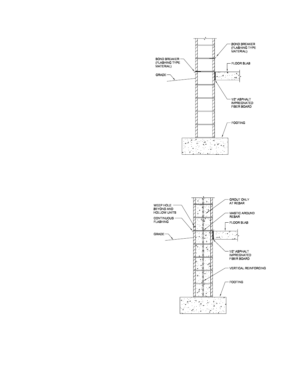
floor line. The detail itself requires careful consideration
(see Figure 1). One must also inform the owner of the antic-
ipated behavior.
It is recommended that the frame drift under the loads
associated with ten-year wind be controlled so as to limit
crack width to
1
/
8
in. when a detail such as that of Figure 1
is used, and
1
/
16
in. when no special detail is used. This
cracked base then becomes the first boundary condition in
the design of the masonry panel. The model for the panel
must show a hinged base rather than a fixed base. The fore-
going limits are applicable to non-reinforced walls. Where
vertical reinforcing is required for strength reasons, it is rec-
ommended that the drift limit be changed to height divided
by 200. A limit of height divided by 100 can be used if a
hinge type base (see Figure 2) can be employed.
DESIGN GUIDE 3, 2ND EDITION / SERVICEABILITY DESIGN CONSIDERATIONS FOR STEEL BUILDINGS / 17
Fig. 1. Masonry horizontal control joint
Fig. 2. Masonry horizontal control joint

The remaining panel boundary elements are the compo-
nents of the structural frame, which require deflection lim-
its compatible with the masonry. Based on numerous finite
element models of wall panels and supporting framing, the
authors have noted two consistent trends. First, almost cat-
egorically, the change from a rigid support to a yielding
support can increase moment magnitudes by a factor of two
to three. Second, because of the great stiffness of the
masonry panel itself, it is very difficult to provide reason-
ably sized support elements with sufficient stiffness to sig-
nificantly alter the distribution of panel shears and
moments. Thus, design and detailing of the masonry is the
critical element in this relationship, not the design of the
steel frame.
A model consisting of non-yielding supports and a fixed
base is not accurate. Fortunately, in practice, the increased
moment results in stresses within the range of ultimate
bending stresses in the masonry and in the case of rein-
forced masonry the material ductility mitigates the problem.
What is obvious is that controlling steel deflections is not
the solution. In order that support deflection not be totally
neglected, a limit of span divided by 240 with maximum
absolute value of 1½ in. is recommended for girts and
columns supporting masonry under a load associated with a
ten-year wind.
One specialized case of masonry wall is that of the wain-
scot wall. The top of this masonry wall is usually six to
eight feet above the floor and the remainder of the wall is
metal panel. The junction between top of the masonry and
bottom of wall panel can be accomplished in three ways:
1. Isolation of masonry and panel with separate supports;
2. Attachment of the wall panel to an angle attached to the
top of the masonry; and
3. Attachment of both the masonry and the panel to a com-
mon girt.
Each method has unique design considerations and is work-
able. As always, their success or failure depends on the
details.
In the first case, the masonry and wall panel girt must be
checked to limit relative deflection so that an air-tight and
water-tight joint can be provided which will move but not
leak. This system has the advantage of a smaller girt since
there is lesser load on the girt.
In the second approach a girt is eliminated. However, the
wall and its connections to the columns must be strong
enough to carry not only the wind load on it but also the
wind from the bottom span of wall panel.
The third approach requires the largest girt, but the prob-
lem of masonry/wall panel differential deflection is elimi-
nated. Additionally, the girt/column connection provides
the top of wall anchor, thus eliminating a connection
between masonry and building column.
The recommended limit for the girt supporting the wall
panel above the masonry wainscot wall (as in the case of the
all metal panel wall) is span divided by 120 using ten-year
wind loads. An absolute maximum deflection depends upon
the girt supported equipment, if any, and the relative deflec-
tion between roof edge or wall base and first interior girt.
The main wind-force-resisting system loads should be used.
For both a full height and wainscot wall, it is not necessary
to combine the drift of the frame and the roof diaphragm or
the deflection of the girt at the top of the wainscot wall.
Both before and after a crack forms at the base of the wall,
the frames, grits and the masonry wall represent a complex
indeterminate system.
Modeling the bare frame, while not perfect, is adequate
for the task at hand. The simple addition of the drift and
deflection values will overestimate the situation and add
unnecessary cost to the construction. The wind load at the
base of a structure is probably over-estimated by current
standards due to obstructions and ground drag. In a life-
safety code, the over-estimate of load is not a detriment. In
a serviceabity check, the over-estimate of load is not neces-
sary and is objectionable.
As mentioned earlier, there is also a concern for parallel
movement of the frame behind the cladding. There should
be isolation between wall and frame by means of sliding or
yielding connections. Thus, the movement is only limited
by the flexibility of the roofing/wall joint and the floor/wall
joint. The practical limitation is joint behavior at the inter-
section of parallel and perpendicular walls as noted earlier.
Frame-Supported Cladding at Columns
The second method of support for cladding, i.e. cladding
that spans between columns, is sometimes used for build-
ings. In this case, the frame carries both the vertical and
horizontal forces from the cladding, but the support points
are limited to points on or very close to the columns. In the
idealized case, there are two support points that carry verti-
cal and lateral loads and two that carry lateral loads only.
These supports must be detailed to slide or yield under hor-
izontal forces in the plane of the panel with the exception of
one joint, which is required for horizontal shear stability.
The success or failure of this method depends on the rela-
tive movement of the support points.
Vertical movement is the result of absolute and relative
column shortening (and lengthening). The vertical move-
ment affects the performance of the panel perimeter caulk
joints. This movement should be limited to about
1
/
4
in., due
to ten-year wind load or 50 percent of design live load. The
other concern is racking of the bay. First, the racking must
be within the limit of movement of the connections, and
secondly the racking must be within the limit of the move-
18 / DESIGN GUIDE 3, 2ND EDITION / SERVICEABILITY DESIGN CONSIDERATIONS FOR STEEL BUILDINGS

ment provided for between panels in adjacent stories. The
junction of four panels, where the sealant takes on a cross
pattern, is a critical location (Bergmann, 1988). Relative
movement between stories can introduce shearing forces in
the intersection of the horizontal and vertical sealants.
While the limit on racking is a function of connection
design and joint detailing, one can use a maximum inter-
story drift of story height divided by 500 using a ten-year
wind load as a target limit with reasonable assurance.
Frame-Supported Cladding for Gravity
Loads Along Spandrels
The third method of support, i.e., support along the span-
drels, is the most complex and results in the most problems.
In this method, there are the concerns of the methods dis-
cussed earlier, with the added issue of deflections of the
perimeter framing. Again there is the concern of determi-
nate versus indeterminate attachment. The timing of the
application of loads is significant. First, deflections prior to
setting of cladding are important since the fabrication of
cladding may, in all likelihood, be based on idealized con-
stant story elevations. Secondly, deflections during the set-
ting of heavy cladding must be considered as component
alignment may be affected. Lastly, deflections after the
completion of cladding must be consistent with its detail-
ing.
It is inevitable that the cladding will not be in the plane
of the perimeter framing, so the effects of cantilever support
deflections and/or the movements created by rotation (tor-
sion) of the parallel spandrel must be considered. In the
case of determinate attachment of cladding, the concerns of
perimeter beam deflection relate to the erection and in-serv-
ice performance of joints and details. In the case of an inde-
terminate system, the concerns must also include a
deflection limit that controls stresses in the cladding mate-
rial.
In general, the vertical deflection of perimeter framing
should be limited to span divided by 480 for total dead load,
with an absolute limit of
3
/
8
in. due to dead loads imposed
prior to setting the cladding and an absolute limit of
5
/
8
in.
dead load deflection after setting the cladding.
The effect of setting heavy units sequentially down the
length of a perimeter framing element should be considered
when the cladding weight exceeds 25 percent of the total
dead load on the beam. In this case, the deflection due to
cladding and initial dead load should be limited to span
divided by 600 with an absolute limit of
3
/
8
in.
The limits on vertical deflection after the completion of
cladding must be consistent with the joints and details and
relate primarily to the relative deflections between floors.
For example, glass can pull out of the glazing stops attached
to the floor above. Interlocking mullion expansion joints
can disengage. Windows in continuous slip heads could jam
or disengage. Precast or stone panel vertical joints can open
excessively at the base and squeeze closed at their tops
(PCI, 1999). To prevent these problems and others like
them, one must limit live load deflection to span divided by
360 with a maximum of
1
/
4
in. to
1
/
2
in. depending on the
details. Consideration must be given to the magnitude of
live load (that is load after erection of cladding). It is the
nature of live load specifications to err on the high side.
Thus, the reasonably expected live load in the perimeter
zone of the building would generally be less than that spec-
ified. This is due to the relatively low density of use of the
floor space near the windows. Also, consider not using the
full live load because the design consideration is the differ-
ential movement between floors. It may be reasonable to
assume some load on all floors (except the top and bottom
stories). For these reasons, consider using 50 percent of the
design live load.
Walls that are continuously supported along a floor or
roof such as masonry walls or stud walls are supported in an
indeterminate manner and require compatibility analysis, or
more commonly strict deflection limits, to control damage
to the cladding.
The limits on deflection given by the Brick Institute of
America (BIA) for lintels are maximum total load deflec-
tions of span divided by 600 but not more than 0.3 in. (BIA,
1987, 1991). The absolute limit governs for spans divided
by 15 feet and is consistent with typical joint details at
ledges and window heads. BIA limits lintel rotation to
1
/
16
in.
The authors have taken this to mean a
1
/
16
in. tip from heel
to toe of a single support angle, which is an approximate
rotation of 1 degree. ACI 531 also gives deflection limits for
masonry beams and lintels as span divided by 360 for total
load and span divided by 600 for dead load only. Limita-
tions for built-up insulation systems on studs are such that
the limits given for the determinate systems would apply to
these as well.
It should be noted that deflection and drift limits must be
compared to calculated deflections, which include the effect
of creep as appropriate, as in the case of composite beams.
Installation of Aluminum Curtain Walls, published by the
American Architectural Manufactures Association
(AAMA) provides a useful, but general, discussion of the
relationship of the curtain wall and the building frame,
focusing on tolerances and clearances.
Special Considerations for Tall Buildings
Many of the issues discussed for column and frame sup-
ported cladding also apply to tall buildings, but there are
additional considerations that apply as buildings increase in
height. The majority of concerns center on the need for an
accurate determination of the deformation and drift behav-
ior of the frame. Needless to say, inaccuracies in modeling
that are inconsequential in a short frame may result in sig-
DESIGN GUIDE 3, 2ND EDITION / SERVICEABILITY DESIGN CONSIDERATIONS FOR STEEL BUILDINGS / 19

nificant problems in a tall frame. For example, the frame
analysis (Griffis, 1993) should “capture all significant”
effects of:
1. Flexural deformation of beams and columns.
2. Axial deformation of columns.
3. Shear deformation of beams and columns.
4. P-
∆ effect.
5. Beam-column joint deformation.
6. Effect of member joint size.
The first four effects are addressed in most currently
available analysis software. The last three may or may not
be addressed, depending on the sophistication of the pro-
gram. The effects on beam-column deformation can be sig-
nificant. An in-depth discussion of this important topic is
beyond the scope of this Guide. The reader is referred to
Charney (1990) for a detailed discussion on beam-column
deformation, including the presentation of an approximate
method to correct for this effect using “modified beam and
column moments of inertia and shear areas to compensate
for deformations occurring inside the joint.” “The P-
∆ effect
can easily increase total frame displacement by 10 to 15
percent depending on frame slenderness” (Griffis, 1993).
An accurate determination of frame stiffness is also impor-
tant in establishing the building period, when assessing
seismic loads, the dynamic (resonant) component of wind
loading, and in determining wind accelerations for evalua-
tion of perception of motion.
Another aspect of tall building behavior as it relates to
cladding behavior is column shortening and differential col-
umn shortening. Design and construction attention must be
given to the issue of column shortening in the form of
movement tolerant joints, adjustable details, and shimming
of the frame as it is being erected. This last item is discussed
further in the section on floors.
20 / DESIGN GUIDE 3, 2ND EDITION / SERVICEABILITY DESIGN CONSIDERATIONS FOR STEEL BUILDINGS

DESIGN GUIDE 3, 2ND EDITION / SERVICEABILITY DESIGN CONSIDERATIONS FOR STEEL BUILDINGS / 21
The performance of exterior walls and roofs is generally
judged by their ability to not leak air or water. The per-
formance of interior partitions and ceilings is largely aes-
thetic and relates to cracks and bows. Most finish materials
are brittle and thus have little tolerance for inadvertent load-
ing due to deflections. The only notable exception to this is
ceiling construction of metal grids and lay-in acoustical
panels.
Support Deflection
One common criterion in literature on this topic is the lim-
itation on floors and roofs supporting plaster ceilings that
live load deflection not exceed span divided by 360. This is
found in AISC ASD Section L3. Likewise, paragraph 5.9
Deflection of the SJI K-Series Joist Specification requires
that design live load deflection not exceed
1
/
360
of span for
floors. Two limits are given for roofs,
1
/
360
of the span where
a plaster ceiling is suspended from the framing and
1
/
240
of
the span for all other cases. The specifying professional is
required to “give due consideration to the effects of deflec-
tion and vibration in the selection of joists.” These require-
ments are repeated in the SJI LH- and DLH-Series
Specification in paragraph 104.10 and in paragraph 1004.7
in the SJI Standard Specifications for Joist Girders.
These limits produce deflected curvatures that are on the
borderline of acceptable visual perceptibility. Other consid-
erations may require stricter absolute limits on deflection.
For example, where drywall partitions meet drywall or plas-
ter ceilings, standard details allow for only
1
/
4
in. to
1
/
2
in. of
movement. This is, in general, a stricter limit than span
divided by 360. An alternative to providing a stiffer struc-
ture is to support the drywall ceilings from ceiling framing
that is supported by the partitions rather than suspend the
ceiling from the structure above. This solution may only be
appropriate for relatively small rooms such as individual
offices.
Another alternative is to enlarge the joint between wall
and ceiling. This would require non-standard detailing and
consequently a higher standard of care. Ceilings of metal
grids and acoustical panels are also of concern. Ceilings of
this construction generally have a high tolerance for distor-
tion due to the loose nature of their assembly. The one
exception to this general characterization is the perimeter
detail. In standard installations this consists of a painted
metal angle attached to the walls around the perimeter of
the room. The metal ceiling grid bears on this angle, as does
the perimeter row of ceiling panels. With this rigid perime-
ter, the remainder of the ceiling (suspended from the floor
above) cannot deflect more than
1
/
4
in. to
1
/
2
in. without
some distress. As in the case with plaster and drywall ceil-
ings, the alternative to controlling deflections in the struc-
ture above is to isolate the ceiling perimeter. This can be
done, but it requires extra hangers and a non-standard
attachment of the perimeter trim. Additionally, a flexible
dust membrane may be needed. In buildings where the ceil-
ing is used as a return air plenum, a detail must be devised
to maintain the effectiveness of this plenum.
The foregoing discussion is directed to downward deflec-
tions of the framing supporting the ceiling from above.
There is also a concern for floor deflections, which draw the
partitions downward relative to the ceiling. This situation is
usually of lesser concern since the deflection magnitude is
the net difference of the deflection of the two levels (except
in the top and bottom stories).
Deflection of floors is also of concern as it relates to the
behavior of partitions. Since the floor supports the walls,
the walls are of necessity forced to conform to the deflected
contour of the floor both as the walls are erected and after
the walls are in place. In general, walls can be thought of as
deep beams or diaphragms. Thus, they have some ability to
span over places where the floor deflects downward beneath
the partition. The most vulnerable point in the wall is at the
upper corners of door openings for two reasons: firstly
because of longitudinal shrinkage of the wall itself, and sec-
ondly because of the discontinuity of the wall acting as a
beam. The door head is the weak point in the overall wall
and can crack as the wall attempts to follow its deflected
support.
Thus, as is frequently the case, the solution to structure-
partition interaction is effective control jointing and isola-
tion. It is recommended that control joints be placed at the
upper corners of doorways and at intervals along walls that
are not pierced by doors. The spacing of such joints is sug-
gested to be 30 ft or closer (U. S. Gypsum, 2000). Other ref-
erences would restrict the aspect ratio of the panel to 2:1 to 3:1
(Nemestothy and Visnovitz, 1988).
Flat and Level Floors
As in the case of a spandrel supporting a curtain wall along
its length, the behavior of floors is sometimes a problem as
they deflect under successive applications of dead and live
load. One common example of this is beam deflection dur-
Chapter 5
Design Considerations Relative to
Interior Partitions and Ceilings

22 / DESIGN GUIDE 3, 2ND EDITION / SERVICEABILITY DESIGN CONSIDERATIONS FOR STEEL BUILDINGS
ing concreting operations and the possibility of complaints
from finishing contractors over uneven floors.
The most common floor construction in many low-rise and
most mid- and high-rise office and other similar structures
consists of a cast-in-place concrete slab on composite steel
deck supported on composite steel beams and girders. In
recent years, situations that have arisen during construction
have raised concerns about the flatness and levelness of
floors and the means required to achieve these specified
conditions. Both the use of higher strengths of steel and the
use of camber in the frame have amplified the degree of
concern over the topic.
The owner/occupant of these structures desires that the
floors be flat and level but also expects to receive the proj-
ect for the most economical price possible. For the sake of
economy, composite construction is often employed. By
their nature, composite beams provide significantly greater
strength and stiffness than the base steel beam in the non-
composite condition. Framing is commonly cambered for
the expected dead load with the expectation that the beams
will deflect to level during concreting. The deck or framing
is rarely shored during concreting operations.
While the framing system described above is common
and efficient, it is not without its pitfalls in design and con-
struction. For example, using the nominal floor elevation
and nominal top of steel as the actual condition, initially the
tops of the cambered beams rise above the plane established
by the nominal top of steel. In all designs, a nominal thick-
ness of concrete is established over the top of the deck. The
slab thickness is generally set by strength requirements and
is frequently part of the fire rating of the floor system.
Tolerances for cast-in-place concrete construction are
established by ACI Committee 117 in its report “Standard
Specifications for Tolerances for Concrete Construction and
Materials (ACI 117, 1990).” In paragraph 4.4.1, the toler-
ance for slabs 12 in. or less in thickness is plus
3
/
8
in. and
minus
1
/
4
in.
The first preference among concrete contractors in cast-
ing slabs is to strike the concrete to a constant elevation
without regard to the contour of the deck and framing.
When beams are cambered and minimum slab thicknesses
are maintained, this approach raises the actual top of con-
crete above the nominal top of concrete, potentially affect-
ing pour stops, stairs, curtain walls, etc. This approach also
increases the volume and weight of concrete on the struc-
ture, which in turn affects the required resistance and
deflection response of the framing. Thus, in most cases, it
becomes necessary to set screeds to follow the curvature of
the cambered beams to maintain the slab thickness within
tolerance. This may also be required to maintain cover over
the top of the shear connectors. Per the AISC LRFD Speci-
fication Section 5a(2), a minimum of 2 in. of concrete is
required over the top of the deck. Screeds may be set to fol-
low the curve of the cambered beams due to either: 1) a lack
of understanding on the part of the concrete contractor as to
the anticipated deflection of the framing, or 2) over cam-
bering of the framing.
The successful concreting of floors on steel deck and
framing is an art. In addition to the skills required to place
and finish concrete, the work is performed on a deflecting
platform. It is essential that the concrete contractor be expe-
rienced in this type of work. Also, the contractor must be
informed as to the basis for the cambers specified and the
expectations of the structural engineer with regard to
deflections during concreting. The Engineer’s expectations
for the behavior of the structure can be conveyed in the con-
struction documents and during a preconstruction meeting.
It is in the nature of structural engineering and design to
overestimate loads and underestimate resistance. With
regard to the calculation of expected deflections during con-
creting, this rubric will likely result in over cambered beams
and the need to have the slab follow the cambered curve.
Ruddy (1986, 1996) in two papers on this subject empha-
sizes the need to accurately determine loads and the deflec-
tion response. For example, he notes that the deck will
deflect during concreting and recommends that the nominal
weight of the concrete slab be increased by ten percent to
account for this. Additionally, while it is essential to
account for the weight of workers and equipment for
strength, these loads are transient and should not be overes-
timated in determining deflection. Perhaps Ruddy’s more
significant insight is that the effects of end connection par-
tial restraint should be considered in the calculation of
deflections even though the members in question are con-
sidered simple span members. Ruddy’s proposal is to
reduce the estimated simple span deflections to 80 percent
of the calculated values when setting cambers.
Specifying Camber and Camber Tolerances
Camber tolerances are established in the AISC Code of
Standard Practice as follows in Section 6.4.4:
“For beams that are equal to or less than 50 ft in
length, the variation shall be equal to or less than
minus zero/plus
1
/
2
in. For beams that are greater than
50 ft in length, the variation shall be equal to or less
than minus zero/plus
1
/
2
in. plus
1
/
8
in. for each 10 ft or
fraction thereof in excess of 50 ft in length.”
These tolerances are set with the worthy goal of ensuring
positive camber, but it should be noted that there is a bias
toward over cambering.
The AISC Code of Standard Practice, in Section 6.4.4,
states: “For the purpose of inspection, camber shall be
measured in the Fabricator’s shop in the unstressed condi-
tion.” This requirement is further amplified in paragraph
8.5.2, which states: “Inspection of shop work by the Inspec-

tor shall be performed in the Fabricator’s shop to the fullest
extent possible.” Paragraph 8.5.4 states: “Rejection of mate-
rial or workmanship that is not in conformance with the
Contract Documents shall be permitted at any time during
the progress of the work.” The inspection of camber is an
exception to this general principle. Unlike other physical
characteristics of a fabricated beam or girder, such as yield
strength, dimensions, welds, etc., the camber in a beam can
change as the member is handled, shipped, unloaded and
raised into position. The Code commentary to paragraph
6.4.4 provides the following explanation of this phenome-
non. Camber can vary from that induced in the shop due to
factors that include:
a. The release of stresses in members over time and in
varying applications:
b. The effects of the dead weight of the member:
c. The restraint caused by the end Connections in the
erected state; and,
d. The effects of additional dead load that may ultimately
be intended to be applied, if any.
Because of the unique nature of camber in beams and the
limits on the inspection for conformity to the project
requirements for camber, it is incumbent on the specifier to
recognize these limits and prepare the Construction Docu-
ments accordingly. The Code of Standard Practice, in Para-
graph 8.1.1, requires that “The Fabricator shall maintain a
quality assurance program to ensure that the work is per-
formed in accordance with the requirements in this Code,
the AISC Specification and the Contract Documents. The
fabricator shall have the option to use the AISC Quality
Certification Program to establish and administer the qual-
ity assurance program.”
The AISC Certification Program for Structural Steel Fab-
ricators is set forth in a document entitled Standard for Steel
Building Structures, 2002. In the section on Fabrication
Process Control, it states “The Fabricator will include addi-
tional ‘special procedures’ that cover fabrication processes
done at the facility (e.g., cambering).” In the section on
Inspection and Testing, the Standard states: “The Fabricator
shall document a procedure for inspection and testing activ-
ities in order to verify that the product quality meets project
requirements. The Fabricator will establish in the procedure
the level and frequency of inspection to assure expected
contract quality.” The Standard goes on to state: “The
inspection procedure shall include receipt, in-process and
final inspection of all product furnished to the project. The
procedure will include any sampling plan, if less than 100
percent, for each type of inspection.”
The inspection procedures prescribed in the Certification
Standard should provide reasonable and documented evi-
dence that camber was provided, meeting project require-
ments. In the absence of a Quality Control program such as
that provided in the Standard, the specifier may wish to
consider requiring specific inspections for the quality con-
trol of camber. Any requirements for “more extensive qual-
ity assurance or inspection…shall be clearly stated in the
Contract Documents, including a definition of the scope of
such inspection,” as provided in paragraph 8.1.3 of the Code
of Standard Practice.
It is common practice not to camber beams when the
indicated camber is
3
/
4
in. or less. The AISC Code of Stan-
dard Practice provides that if no camber is specified, hori-
zontal members are to be fabricated and erect beams with
“incidental” camber upward. The AISC Code also provides
that beams received by the Fabricator with 75 percent of the
specified camber require no further cambering. Because of
the provisions, it should be expected that all framing mem-
bers should have at least some upward camber at the initia-
tion of concreting operations. However, given the limits
presented there will be instances of downward deflection
below level during concreting. To control the excessive
accumulation of concrete in the deflected bay Ruddy
(1986), quoting Fisher/West in the first edition of this
Guide, recommends that the total accumulated deflection in
a bay due to dead load be limited to L/360, not to exceed 1 in.
The foregoing discussion on determining and specifying
camber is intended to impress upon the designer of the
framing to be judicious in determining cambers and to be
pro-active in communicating the basis of the camber deter-
minations.
Maintaining Floor Elevation
This discussion is premised on the fact the steel framing is
set at the nominal top of steel elevation. Needless to say, the
actual elevation of the steel framing can vary as permitted
by the tolerances established in the AISC Code of Standard
Practice. These tolerances are presented in Section
7.13.1.2(b), which permits a deviation in the dimension
from the working point at the end of a beam connection to
a column to the upper finished splice line to be “equal to or
less than plus
3
/
16
in. and minus
5
/
16
in. Note that all other
things being equal, the tolerances for the actual framing
approximate the deviations permitted by ACI 117 for the
variation in slab thickness. AISC Code of Standard Practice
Section 6.4.1 limits the variation in length of columns fitted
to bear to plus or minus
1
/
32
in.
In tier construction, these small variations can combine
with differential thermal and differential dead load shorten-
ing to create deviation in splice elevations in floors as the
frame rises. These differences must be shimmed out as the
frame is erected to maintain reasonable control of actual
floor elevations and differential top of steel elevations
across a floor. It is common in mid- and high-rise construc-
DESIGN GUIDE 3, 2ND EDITION / SERVICEABILITY DESIGN CONSIDERATIONS FOR STEEL BUILDINGS / 23

tion to obtain an as-erected survey of the frame. This survey
can be used to direct the concrete contractor as to what
adjustments must be made to maintain the slab thicknesses
and the top of concrete elevations specified.
The reader is encouraged to refer to the papers cited in
the References by Ruddy (1986, 1996), Tipping and
Suprenant (1991, 1991), Suprenant (1990), Tipping (1993),
and Ritchie and Chien (1992) for a more complete treat-
ment of this topic. Apart from the deflection standards
implied in this Guide, there are no published limits for the
dead load deflection of floor beams.
Both the Steel Deck Institute (SDI, 2000) and the Amer-
ican Society of Civil Engineers in its Specifications for the
Design and Construction of Composite Slabs, ASCE 3-91
(ASCE, 1991), give limits for the deflection of metal deck
acting as a form. Both give a limit of span divided by 180,
with a maximum of
3
/
4
in. deflection under the weight of wet
concrete and the weight of the deck (SDI 3.2c (Non-Com-
posite)/3.3(Composite) and ASCE 3 2.2.6). SDI also limits
the maximum deflection for form decks to the same con-
straints. The limit on deflection under superimposed load
on the composite section is given as span divided by 360 in
SDI para. 5.4 (Composite). The ASCE document limits
deflection for a range of span divided by 180 to span
divided by 480 depending on conditions. This is presented
in Table 2 in the ASCE document, which is an adoption of
Table 9.5(b) in ACI 318-89.
Drift, Deflection, and Racking
There is also a concern for partition racking induced by
interstory drift. One published source gives drift indices
(deflection divided by height) of 0.0025 (1/400) for “first
distress” and 0.006 (1/167) for ultimate behavior for dry-
wall on studs (Freeman, 1977). The following deflection
limits for both composite and non-composite beams and
frame drift are recommended:
For dead load (roof): No limit except (1) as controlled by
ponding considerations, (2) as controlled by roofing per-
formance considerations and (3) as controlled by skylight
performance. There is no limit as it relates to partitions and
ceilings, since these materials are installed after the dead
load is in place. In the case of roofs that are concreted, the
limits for floors would apply.
For dead load (floor): Span (L) divided by 360 with a
maximum of 1 in. This is to be the accumulated deflection
in a bay. This is greater than the deflection allowed by ACI
tolerances and requires that this deviation be adequately
explained and accounted for in the plans and specifications.
This deflection limit does not necessarily control ponding
of wet concrete, which should be checked separately. The
loading for this deflection check is the weight of wet con-
crete, the weight of steel deck and the weight of steel fram-
ing. For composite floors, the deflection limits should be
applied to the instantaneous deflection plus one half of the
expected creep deflection.
For live load (roof): Span (L) divided by 360 where plas-
ter ceilings are used and span (L) divided by 240 otherwise.
A maximum absolute value that is consistent with the ceil-
ing and partition details must also be employed. This
absolute limit should be in the range of
3
/
8
in. to 1 in. Note
that movable and demountable partitions have very specific
tolerances required for them to function. These special lim-
its are unique to each model and manufacturer and must be
strictly adhered to.
In most jurisdictions there is a distinction between live
load and snow load. These deflection limits should be
checked using 50 percent of the minimum code specified
live load or the 50-year roof snow load (including drifting),
whichever produces the greater deflection. It should be
noted that roof snow loads are used at full magnitude due to
their probability of occurrence whereas minimum roof live
loads are reduced due to their transitory nature (rain, main-
tenance, etc.). In those jurisdictions where there is snow, but
the roof load is expressed as live load, the use of snow loads
from model codes is recommended.
For live load (floor): Span (L) divided by 360 with a
maximum absolute value of 1 in. across the bay with 50 per-
cent of design live load (unless the code imposes a stricter
standard). The comments in the roof section relating to par-
titions also apply to floor deflection. Additionally, the lim-
its include creep deflection, which can be significant in the
long term.
For lateral load: Story height (H) divided by 500 for
loads associated with a ten-year wind for interstory drift
using the bare frame stiffness.
As always, these limits are intended to be reasonable lim-
its in general. Coordination is required between the
deflected structure and the non-structural components to
ensure that the limits are appropriate for any particular project.
24 / DESIGN GUIDE 3, 2ND EDITION / SERVICEABILITY DESIGN CONSIDERATIONS FOR STEEL BUILDINGS

DESIGN GUIDE 3, 2ND EDITION / SERVICEABILITY DESIGN CONSIDERATIONS FOR STEEL BUILDINGS / 25
Human response to vibrations and accelerations and the
reaction of machines to vibrations are also serviceability
concerns. In general, human response to human or machine
induced vibration takes a range from no concern, through
moderate objection and concern for the building integrity, to
physical sickness and rejection of the structure. In the case
of machinery the function of the device can be impaired or
destroyed. In general, the quality of the output of the
machine is the standard of success or failure, whereas for
human response the criteria are largely subjective.
Regarding the structural framework of a building, human
response to vibrations can be limited to two categories: (1)
frame behavior in response to wind forces or earthquake
forces; and (2) floor vibration. In the opinion of the authors
and other sources, frame behavior in response to lateral
loads has not been a problem for low-rise multi-story build-
ings, which are generally stiff enough so that wind induced
vibrations are not a problem. This is, of course, not the case
for tall buildings. This topic is treated in the section on tall
building acceleration induced by wind load.
Human Response to Vibration
Floor vibration and human response to it are of concern for
all buildings. Currently, the state of the art treatise on this
topic is AISC Design Guide 11, Floor Vibrations Due to
Human Activity by Murray, Allen and Ungar, (AISC, 1997).
It would be redundant for this Guide to address this topic
and, thus, the reader is referred to Design Guide 11 for a
thorough explanation of the analysis and design considera-
tions for floor vibration design.
Machines and Vibration
The behavior of machines in structures as it relates to vibra-
tion can be treated generally whether the machine is induc-
ing the vibration or being acted upon by vibration induced
by other sources. The effects of vibrations caused by
machinery can be mitigated in the following ways:
1. The machine may be balanced or rebalanced.
2. The vibration source may be removed, relocated or
restricted. For example, crane runways should not be
attached to office areas in plants.
3. Damping in the form of passive or active devices may be
added.
4. Isolation may be employed using soft springs or isola-
tion pads.
5. The adjacent structure, floor, etc., may be tuned to a nat-
ural frequency substantially different from the critical
frequency. For example, the floor or its components
should have a frequency that is either less than one-half
or greater than one and one-half times the fundamental
frequency of the equipment.
Needless to say, the proper functioning of equipment is
critical in any operation.
Thus, in the design of facilities such as labs, medical or
computer areas and manufacturing plants, vibration control
is essential and the active participation of the owner and
equipment suppliers is required to set limits and provide
performance data.
AISC Design Guide 11 also provides a discussion on the
design of floors for equipment that is sensitive to vibration.
Tall Building Acceleration—Motion Perception
Perception to building motion under the action of wind
(Griffis, 1993) may be described by various physical quan-
tities including maximum values of velocity, acceleration,
and rate of change of acceleration, sometimes called jerk.
Since wind-induced motion of tall buildings is composed of
sinusoids having a nearly constant frequency (f) but varying
phase, each quantity is related by the constant 2
πf where f
is the frequency of motion
V = (2
πf)D
A = (2
πf)
2
D
J = (2
πf)
3
D
where D, V, A, and J are maximum displacement, velocity,
acceleration, and jerk respectively.
Human response to motion in buildings is a complex phe-
nomenon involving many psychological and physiological
factors. It is believed that human beings are not directly sen-
sitive to velocity if isolated from visual effects because,
once in motion at any constant velocity, no forces operate
upon the body to keep it in such motion. Acceleration, on
the other hand, requires a force to act, which stimulates var-
ious body organs and senses. Some researchers believe that
the human body can adapt to a constant force acting upon it
whereas with changing acceleration (jerk) a continuously
Chapter 6
Design Considerations Relative to Vibration/Acceleration

26 / DESIGN GUIDE 3, 2ND EDITION / SERVICEABILITY DESIGN CONSIDERATIONS FOR STEEL BUILDINGS
changing bodily adjustment is required. This changing
acceleration may be an important component of motion per-
ception in tall buildings. It appears that acceleration has
become the standard for evaluation of motion perception in
buildings because it is the best compromise of the various
parameters. It also is readily measurable in the field with
available equipment and has become a standard for com-
parison and establishment of motion perception guidelines
among various researchers around the world.
Factors Affecting Human Response to Building Motion
Perception and tolerance thresholds of acceleration (Griffis,
1993; Kahn and Parmelee, 1971) as a measure of building
motion are known to depend on various factors as described
below. These factors have been determined from motion
simulators that have attempted to model the action of build-
ings subjected to wind loads.
1. Frequency or Period of Building. Field tests have shown
that perception and tolerance to acceleration tend to
increase as the building period increases (frequency
decreases) within the range of frequency commonly
occurring in tall buildings.
2. Age. The sensitivity of humans to motion is an inverse
function of age, with children being more sensitive than
adults.
3. Body Posture. The sensitivity of humans to motion is
proportional to the distance of the person’s head from the
floor; the higher the person’s head, the greater the sensi-
tivity. Thus, a person’s perception increases as he goes
from sitting on the floor, to sitting in a chair, to standing.
However, since freedom of the head may be important to
motion sensitivity, a person sitting in a chair may be
more sensitive than a standing person because of the
body hitting the back of the chair.
4. Body Orientation. Humans tend to be more sensitive to
fore-and-aft motion than to side-to-side motion because
the head can move more freely in the fore-and-aft direc-
tion.
5. Expectancy of Motion. Perception threshold decreases if
a person has prior knowledge that motion will occur.
Threshold acceleration for the case of no knowledge is
approximately twice that for the case of prior knowl-
edge.
6. Body Movement. Perception thresholds are higher for
walking subjects than standing subjects, particularly if
the subject has prior knowledge that the motion will
occur. The perception threshold is more than twice as
much between the walking and standing case if there is
prior knowledge of the event, but only slightly greater if
there is no knowledge of the event.
7. Visual Cues. Visual cues play an important part in con-
firming a person’s perception to motion. The eyes can
perceive the motion of objects in a building such as
hanging lights, blinds, and furniture. People are also very
sensitive to rotation of the building relative to fixed land-
marks outside.
8. Acoustic Cues. Buildings make sounds as a result of
swaying from rubbing of contact surfaces in frame
joints, cladding, partitions, and other building elements.
These sounds and the sound of the wind whistling out-
side or through the building are known to focus attention
on building motion even before subjects are able to per-
ceive the motion, and thus lower their perception thresh-
old.
9. Type of Motion. Under the influence of dynamic wind
loads, occupants of tall buildings can be subjected to
translational acceleration in the x- and y-direction and
torsional acceleration as a result of building oscillation
in the along-wind, across-wind, and torsional directions,
respectively. While all three components contribute to
the response, angular motion appears to be more notice-
able to occupants, probably caused by an increased
awareness of the motion from the aforementioned visual
cues. Also, torsional motions are often perceived by a
visual-vestibular mechanism at motion thresholds,
which are an order of magnitude smaller than those for
lateral translatory motion (Kareem, 1985).
Root-Mean-Square (RMS) Acceleration Versus
Peak Acceleration
A review of the literature on the subject of motion percep-
tion as measured by acceleration shows a difference in the
presentation of the results. Some report root-mean-square
or RMS accelerations and some researchers report maxi-
mum or peak acceleration. This dual definition has
extended into establishing standards for motion perception.
Most of the research conducted on motion perception has
been with motion simulators subjected to sinusoidal motion
with varying frequency and amplitude. In these tests it has
been common to report the results in maximum or peak
acceleration since that was the quantity directly measured.
It should be pointed out that for sinusoidal acceleration, the
peak is equal to times the RMS value. It appears that
wind tunnel research has tended to report peak acceleration
or both peak and RMS in order to correlate the wind tunnel
studies with these motion simulation tests.
Many researchers believe that, when the vibration per-
sists for an extended period of time (10 to 20 minutes) as is
2
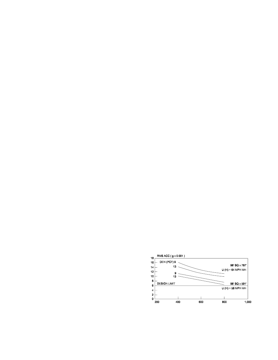
common with windstorms having a ten-year mean recur-
rence interval, RMS acceleration is a better indicator of
objectionable motion in the minds of building occupants
than isolated peak accelerations that may be dampened out
within a few cycles (ISO, 1984; Hansen, Reed and Vanmar-
cke, 1973; Islam, Ellingwood and Corotis, 1990 and Tallin
and Ellingwood, 1984). Also, the RMS statistic is easier to
deal with during the process of temporal and spatial aver-
aging because the 20-minute averaging period for a storm
represents a time interval over which the mean velocity
fluctuates very little.
The relationship between peak and RMS accelerations in
tall buildings subjected to the dynamic action of wind loads
has been defined by the peak factor, which varies with
building frequency, but is oftentimes taken as 3.5. Correla-
tion between peak and RMS accelerations in tall building
motion may be made using this peak factor.
Relationship Between Building Drift
and Motion Perception
Engineers designing tall buildings have long recognized the
need for controlling annoying vibrations to protect the psy-
chological well being of the occupants. Prior to the advent
of wind tunnel studies this need was addressed using rule-
of-thumb drift ratios of approximately 1/400 to 1/600 and
code specified loads. Recent research (Islam, Ellingwood
and Corotis, 1990), based on measurement of wind forces in
the wind tunnel, has clearly shown that adherence to com-
monly accepted lateral drift criteria, per se, does not explic-
itly ensure satisfactory performance with regard to motion
perception.
The results of one such study (Islam, Ellingwood and
Corotis, 1990) are plotted in Figure 3 for two square build-
ings having height/width ratios of 6/1 and 8/1 where each is
designed to varying drift ratios. Plots are shown of com-
bined transitional and torsional acceleration as a function of
design drift ratio. At drift ratios of 1/400 and 1/500 neither
building conforms to acceptable standards for acceleration
limits. The reason that drift ratios by themselves do not ade-
quately control motion perception is because they only
address stiffness and do not recognize the important contri-
bution of mass and damping, which together with stiffness,
are the predominant parameters affecting acceleration in tall
buildings.
Human Response to Acceleration
Considerable research in the last 20 years has been con-
ducted on the subject of determining perception threshold
values for acceleration caused by building motion (Chen
and Robertson, 1972; Khan and Parmelee, 1971 and ASCE,
1981). Much of this work has also attempted to formulate
design guidelines for tolerance thresholds to be used in the
design of tall and slender buildings.
Some of the earliest attempts to quantify the problem
were performed by Chang (Chang, 1967 and Chang, 1972)
who proposed peak acceleration limits for different comfort
levels that were extrapolated from data in the aircraft indus-
try. Chang’s proposed limits are stated as follows:
Peak Acceleration
Comfort Limit
< 0.5% g
Not Perceptible
0.5% to 1.5% g
Threshold of Perceptibility
1.5% to 5.0% g
Annoying
5% to 15.0% g
Very Annoying
> 15% g
Intolerable
Design of Tall Buildings for Acceleration
The design of most tall buildings is controlled by lateral
deflection (Griffis, 1993) and most often by perception to
motion. Indeed, this characteristic is often proposed as one
definition of a “tall” building.
While the problem of designing for motion perception in
tall buildings is usually solved by conducting a scale model
force-balance or aeroelastic test in the wind tunnel, certain
criteria have been established to aid the designer. Empirical
expressions now exist (Irwin, Ferraro and Stone, 1988;
Islam, Ellingwood and Corotis, 1990 and National
Research Council of Canada, 1990) that allow approximate
evaluation of the susceptibility of a building to excessive
motion. This can be very helpful in the early design stages
particularly where geometry, site orientation, or floor plan
is not yet fixed.
Generally, for most tall buildings without eccentric mass
or stiffness, the across-wind response will predominate if
(WD)
0.5
/H < 0.33 where W and D are the across-wind and
along-wind plan dimensions respectively and H is the build-
ing height.
In examining the across-wind proportionality, which
often-times is the predominant response, it is possible to
make the following deductions (Griffis, 1993):
DESIGN GUIDE 3, 2ND EDITION / SERVICEABILITY DESIGN CONSIDERATIONS FOR STEEL BUILDINGS / 27
Fig. 3. RMS Accelerations vs. Drift Index
1. If stiffness is added without a change in mass, accelera-
tion will be reduced in proportion to 1/N
1.54
, which is
proportional to 1/K
0.77
, where N is the frequency (hertz),
K is the generalized stiffness (2
πN)
2
× M and M is the
generalized mass of the building
where m
i
is mass of floor i and
φ
i
is modal coordinate at
floor i, normalized so that
φ = 1 at (Z) = H, building
height.
2. If mass is added throughout the building without chang-
ing the stiffness, acceleration will be reduced in propor-
tion to 1/M
0.23
.
3. If mass is added with a proportionate increase in stiffness
so that N does not change, then the acceleration will be
reduced in proportion 1/M or 1/K.
4. If additional damping is added, then the acceleration will
be reduced in proportion to 1/
ξ
0.5
, where
ξ is the damp-
ing ratio.
It should be noted (Griffis, 1993) that torsional response
can be important even for symmetrical buildings with uni-
form stiffness. This is because a torsional wind loading can
occur from unbalance in the instantaneous pressure distri-
bution on the building surface.
Oftentimes, in very slender buildings, it is not possible to
obtain satisfactory performance, given building geometry
and site constraints, by adding stiffness and/or mass alone.
The options available to the engineer in such a case involve
adding additional artificial damping and/or designing mass
or pendulum dampers to counteract the sway (Grossman,
1990).
Numerous high-rise buildings have been designed and
are performing successfully (Griffis, 1993) all over the
world. Many have been designed according to an “unoffi-
cial” standard defined in Table 2. Both peak acceleration
and RMS accelerations are used, their relationship gener-
ally defined by the use of a peak factor, g
p
, equal to approx-
imately 3.5-4.0. The true peak factor for a building, which
relates the RMS loading or response to the peak, can be
determined in a wind tunnel aeroelastic model study. Target
peak accelerations of 21 milli-g’s and 15 milli-g’s are often
used for commercial and residential buildings respectively
(note: 1 milli-g = 0.001
× g = 0.0322 ft/sec
2
). Correspond-
ing RMS values are proportionally reduced accordingly
using the appropriate peak factor. A stricter standard is
often applied to residential buildings for the following rea-
sons:
1. Residential buildings are occupied for more hours of the
day and week and are therefore more likely to experience
the design storm event.
2. People are less sensitive to motion when at work than
when in the home at leisure.
3. People are more tolerant of their work environment than
of their home environment.
4. Occupancy turnover rates are higher in office buildings
than in residential buildings.
5. Office buildings are more easily evacuated in the event
of a peak storm event.
The apparent shortcoming in the standard defined by
Table 2 is the fact that the tolerance levels are not related to
building frequency. Research has clearly shown a relation-
ship between acceptable acceleration levels and building
frequency. Generally higher acceleration levels can be tol-
erated for lower frequencies.
The International Organization for Standardization has
established a design standard for occupant comfort in fixed
structures subjected to low frequency horizontal
motion—ISO Standard 6897-1984 (ISO, 1984).
28 / DESIGN GUIDE 3, 2ND EDITION / SERVICEABILITY DESIGN CONSIDERATIONS FOR STEEL BUILDINGS
2
1
n
i i
i
m
−
φ
∑
Table 2. (Griffis, 1993)
Traditional Motion Perception (Acceleration) Guidelines*
Ten-year Mean Recurrence Interval
Root-mean-square (RMS)
Acceleration (Milli-g)
Occupancy
Type
Peak Acceleration
(Milli-
g)
1
≤≤ T < 4
0.25 <
f
≤≤ 1.0
(
g
p
≈≈ 4.0)
4
≤≤ T < 10
0.1 <
f
≤≤ 0.25
(
g
p
≈≈ 3.75)
T
≥≥10
f
≤≤ 0.1
(
g
p
≈≈ 3.5)
Commercial
Residential
15-27
Target 21
10-20
Target 15
3.75-6.75
Target 5.25
2.50-5.00
Target 3.75
4.00-7.20
Target 5.60
2.67-5.33
Target 4.00
4.29-7.71
Target 6.00
2.86-5.71
Target 4.29
Notation:
T = period (seconds), f = frequency (hertz), g
p
= peak factor
1 milli-
g = 0.001
× g = 0.0322 ft/sec
2
*RMS and peak accelerations listed in this table are the traditional “unofficial” standard applied in U.S.
practice based on the author’s experience.

DESIGN GUIDE 3, 2ND EDITION / SERVICEABILITY DESIGN CONSIDERATIONS FOR STEEL BUILDINGS / 29
The assortment of equipment used in buildings is many and
varied. This discussion will be limited to equipment that is
a permanent part of the building and will cover elevators,
conveyors, cranes and mechanical equipment.
Elevators
Elevators are of two types: hydraulic and traction.
Hydraulic elevators are moved by a piston, which is gener-
ally embedded in the earth below the elevator pit. Traction
elevators are moved by a system of motors, sheaves, cables
and counterweights. In both types the cars are kept in align-
ment by tee-shaped tracks, which run the height of the ele-
vator shafts. Such tracks are also used to guide the
counterweight in traction elevators.
Elevators impose few limits on deflection other than
those previously mentioned in the sections on cladding and
partitions. A building drift limit of height (H) divided by
500 calculated on the primary structure using ten-year
winds will provide adequate shaft alignment for low-rise
buildings. In addition to this static deflection limit, proper
elevator performance requires consideration of building
dynamic behavior. Design of elevator systems (guide rails,
cables, sheaves) will require knowledge of predominant
building frequencies and amplitude of dynamic motion.
This information should be furnished on the drawings or in
the specifications (Griffis, 1993). The vertical deflection
limits given for floors in the partition section will provide
adequate control on the vertical location of sills. The only
extraordinary requirement is found in ANSI/ASME A17.1
(ANSI, 2002) rule 105.5 which states, “The allowable
deflections of machinery and sheave beams and their imme-
diate supports under static load shall not exceed 1/1666 of
the span.” The term “static load” refers to the accumulated
live and dead loads tributary to the beams in question
including the unfactored elevator loads.
Although it would not be required by a strict reading of
rule 105.5 the authors recommend that the span divided by
1666 limit be used for the girders (if any) that support the
beams. However, the limit need not be applied to the accu-
mulated deflection in the bay.
Conveyors
It is very difficult to give clear-cut serviceability guidelines
relative to the performance of conveyors due to their diverse
configurations and the diverse nature of the materials con-
veyed. However, the following comments are offered.
The key to conveyor performance is the maintenance of
its geometry, especially in the area of switches and transfer
points. In general, the construction of conveying equipment
is flexible enough to absorb some distortion due to differ-
ential deflection of support points. Thus, the deflection lim-
its recommended in the sections on roofs and floors would
be appropriate for the design of roofs and floors supporting
conveyors, i.e., span divided by 150 to 240 for roofs and
span divided by 360 for floors for live load including con-
veyor load. As always, the conveyor supplier must account
for support point deflection where sections are supported
with an indeterminate arrangement of supports.
There are three areas of special concern. First, because
conveyors are rarely attached to all roof members, there
may be cases where the differential deflection places unex-
pected loads on the deck and deck fasteners, which may
result in localized distress. Secondly, heavy conveyor loads
may cause stress reversals in light and lightly loaded roofs,
which must be accounted for in this design. Third, convey-
ors can also cause local member distortions when they are
not properly connected to the framing. Because of the
potential for interface problems, it is essential that the con-
veyor supplier’s criteria be discussed and incorporated into
the design.
Cranes
There are two categories of movement related to the opera-
tion of cranes. First, there are those building movements
induced by the crane operation that affect the performance
of the building. The limits given in the previous sections are
appropriate for the control of building movements induced
by crane operation. The second category of movements
includes those induced by other loads (perhaps in combina-
tion with crane forces), which affect the performance of the
cranes themselves. This second area will be covered here.
Three types of cranes will be discussed: pendant-operated
traveling cranes, cab-operated traveling cranes, and jib
cranes. The reader should refer to ASCE 7-02 for its treat-
ment of crane loads (Section 4.10) as a special case of live
loads.
Pendant-Operated Cranes
For pendant-operated cranes, there are less strict require-
ments. The controls related to other aspects of building per-
Chapter 7
Design Considerations Relative to Equipment

30 / DESIGN GUIDE 3, 2ND EDITION / SERVICEABILITY DESIGN CONSIDERATIONS FOR STEEL BUILDINGS
formance will suffice. However, it should be noted that in
the authors’ experience, buildings designed with a limit on
drift of height divided by 100 can exhibit observable move-
ments during crane operation and it is recommended that
this be reviewed with the building owner at the design stage.
Cab-Operated Cranes
A drift limit for cab-operated cranes is required so that the
operators will perceive the system as safe. The limit for drift
in the direction perpendicular to the runways is suggested to
be height divided by 240, with a maximum of 2 in. (Fisher,
2004). This displacement is to be measured at the elevation
of the runways. The appropriate loading is either the crane
lateral force or the lateral loads associated with a ten-year
wind on the bare frame. The crane lateral loads are those
specified by the AISC Specification (which refers to ASCE
7-02) or the AISE Specification, as appropriate.
The longitudinal displacement of crane runways is rarely
of concern when hot-rolled shapes are used in the X-brac-
ing. If, on the other hand, rigid frames are used, column
bending may result in an excessively limber structure. In the
absence of any standard for this movement, the authors pro-
pose using the same limits as those proposed above for
movements perpendicular to the runways. The loadings for
this condition are the crane tractive forces and bumper
forces. Consideration must also be given to account for the
longitudinal movement that results from column torsional
rotations at bracketed runway supports.
Another category of movements includes those that affect
the lateral alignment of the runways. First, the lateral
deflections of the runways themselves should be limited to
span divided by 400 to avoid objectionable visual lateral
movements. The loading in this case is the lateral crane
force (CMAA, 1999). Secondly, the relative lateral move-
ments of support points must be controlled to prevent the
runways from moving apart or together. This will prevent
the wheels from either jumping the rails or alternatively
having the flanges bind against the rails.
Loads affecting the inward or outward movement of sup-
port points are those applied to the structure after the align-
ment of the rails. Inward movement is by and large the
result of crane loads, whereas outward movements are
caused by roof loads, chiefly high snow loads.
The allowable amount of inward movement is controlled
by the arrangement and proportions of the wheel flange
spacing and should be coordinated with the crane supplier.
The control of inward movements can be on the order of
1
/
2
in.
total.
Outward column deflections at crane runway elevations
should be limited so that the total spread of the runways will
not exceed 1 in. The appropriate loading is snow load. It is
suggested that the roof snow load be taken as zero in areas
where the 50-year snow is 13 psf or less. When evaluating
this differential movement, 50 percent of the roof snow load
should be taken in areas where the roof snow load is
between 13 psf and 31 psf and three quarters of the roof
snow should be used where the roof snow load is greater
than 31 psf .
Jib Cranes
Jib cranes are usually attached to building columns. The
principal concern as it relates to deflections is that the drop
of the outboard end of the jib cannot be so much as to pre-
vent the trolley from moving back towards the column with
reasonable effort. The limit of the drop of the outboard end
should be a maximum of the jib boom length divided by
225. This movement at the end of the jib is the summation
of the cantilever behavior of the jib itself plus the bending
of the column due to the jib reaction. This second compo-
nent may be significant when the jib is rotated so that it
applies its loads to the weak axis of the column.
Crane Runways
Crane runways must also be controlled for vertical deflec-
tions. Such deflections are usually calculated without an
increase for vertical impact. The deflection limits for vari-
ous crane types and classes are given below.
Top running cranes:
CMAA Classes A, B and C:
Span divided by 600
(CMAA, 1999)
CMAA Class D:
Span divided by 800
CMAA Classes E and F:
Span divided by 1000
(AISE, 2003)
Underhung and monorail cranes:
CMAA Classes A, B and C:
Span divided by 450
Note: Underhung cranes with more severe duty cycles
must be designed with extreme caution and are not rec-
ommended.
AISE Technical Report No. 13 (AISE, 2003) also pro-
vides deflection limits for crane runway girders. They are
established based on the Class of Mill Building, A through
D as follows:
Class A Buildings
Span divided by 1000
Class B Buildings
Span divided by 1000
Class C Buildings
Span divided by 600
Class D Buildings
Span divided by 600
Mechanical Equipment
Mechanical equipment for buildings generally consists of
piping, ductwork, exhaust hoods, coils, compressors,

pumps, fans, condensers, tanks, transformers, switchgear,
etc. This equipment can be dispersed throughout the build-
ing, collected into mechanical rooms and/or located on the
roof in the form of pre-engineered package units. The key
feature of this equipment is that it represents real loads as
opposed to code specified uniform loads, which may or
may not ever exist in their full intensity. Because of this, a
degree of extra attention should be applied to the control of
deflections as they relate to mechanical equipment.
This is especially true where the mechanical equipment
loads are the predominant part of the total loads on a given
structure. Special Attention should be given to the tilting
and racking of equipment, which, if excessive, could impair
the function of the equipment and to differential deflection,
which could deform or break interconnecting piping or con-
duits. While the actual deflection limits on each project
should be carefully reviewed with the mechanical engineers
and equipment suppliers, it can be stated that buildings
designed to the standard span divided by 150 to 240 for
roofs and span divided by 360 for live loads have generally
performed well.
DESIGN GUIDE 3, 2ND EDITION / SERVICEABILITY DESIGN CONSIDERATIONS FOR STEEL BUILDINGS / 31

DESIGN GUIDE 3, 2ND EDITION / SERVICEABILITY DESIGN CONSIDERATIONS FOR STEEL BUILDINGS / 33
Allen, D.E., and J.H. Rainer, Floor Vibration, Canadian
Building Digest–Division of Building Research, National
Research Council Canada, September 1975.
Aluminum Curtain Wall Design Manual, American Archi-
tectural Manufacturers Association, Schaumburg, Illi-
nois, 1996.
Approval Guide, 2000—Equipment, Materials, Service for
Conservation of Property, Factory Mutual Research Cor-
poration, an FM Global Affiliate, 2000.
Architectural Precast Concrete, Prestressed Concrete Insti-
tute, Chicago, 1973.
Bergmann, Roland, “Structural Serviceability Aspects of
Building Envelopes in Tall Buildings,” Proceedings,
Symposium/Workshop on Serviceability of Buildings,
National Research Council Canada, May 1988.
Building Code Requirements for Concrete Masonry Struc-
tures and Commentary (ACI 530), American Concrete
Institute, 2002.
Building Code Requirements for Reinforced Concrete (ACI
318-02), American Concrete Institute, 2002.
Carter, Charles J. and Jiahong Zuo, “Ponding Calculations
in LRFD and ASD,” AISC Engineering Journal, Third
Quarter, 1999.
Cermak, J., Boggs, D., Paper to be published.
Chang, F., “Wind and Movement in Tall Buildings,” Civil
Engineering Magazine, ASCE, August 1967.
Chang, F.K., “Human Response to Motions in Tall Build-
ings,” Paper presented at ASCE National Environmental
Engineering Meeting, Houston, Texas, October 16-
22,1974.
Chen, P.W. and L.E. Robertson, “Human Perception
Thresholds of Horizontal Motion,” Journal of Structural
Engineering, ASCE, Vol. 98, No. ST8, August 1972.
Churches, C.H., Emile W.J. Troup, and Carl Angeloff,
Open-Deck, Steel-Framed Parking Structures. AISC
Design Guide 18. American Institute of Steel Construc-
tion, Chicago, 2003.
Code of Standard Practice for Steel Bridges and Buildings,
American Institute of Steel Construction, 2000.
Safety Code for Elevators and Escalators, A17.1, American
National Standards Institute, 2002.
Ellingwood, Bruce, and Andrew Tallin, “Structural Service-
ability: Floor Vibrations,” Journal of Structural Engi-
neering, American Society of Civil Engineers, Vol. 110,
No. 2, February 1984.
Ellingwood, Bruce, “Serviceability Guidelines for Steel
Structures,” Proceedings, 1988 National Steel Construc-
tion Conference, American Institute of Steel Construc-
tion, 1988.
Expansion Joints in Buildings, Federal Construction Coun-
cil, Technical Report No. 65, National Academy of Sci-
ences-National Research Council, Washington, D.C.
Fintel, Mark, S. K. Ghosh and Hal Iyengar, Column Short-
ening in Tall Structures—Prediction and Compensation,
Skokie, Illinois, 1987.
Fisher, James M. and Donald R. Buettner, Light and Heavy
Industrial Buildings, American Institute of Steel Con-
struction, September 1979.
Fisher, James M., “Industrial Buildings: Guidelines and
Criteria,” Engineering Journal, American Institute of
Steel Construction, Vol. 21, No. 3, 1984.
Fisher, James M., Industrial Buildings—Roofs to Column
Anchorage, AISC Design Guide 7, American Institute of
Steel Construction, Chicago, 2004.
Freeman, S. A., “Racking Tests of High Rise Partitions,”
Journal of Structural Engineering, American Society of
Civil Engineers, Vol. 103, No. 8, August 1977.
Galambos, T. V., P. L. Gould, M. K. Ravindra, H. Sury-
outomo, and R. A. Crist, Structural Deflections: A Liter-
ature and State of the Art Survey, Washington, D.C.: U.S.
Department of Commerce, National Bureau of Stan-
dards, 1973.
Galambos, Theodore V. and Bruce Ellingwood, “Service-
ability Limit States: Deflection,” Journal of Structural
Engineering, American Society of Civil Engineers, Vol.
112, No. 1, January 1986.
Griffis, L. G., “Serviceability Limit States under Wind
Load,” Engineering Journal, American Institute of Steel
Construction, 1993.
Grossman, J.S., “Slender Concrete Structures—The New
Edge,” ACI Structural Journal, Volume 87, No. 1, Janu-
ary/February 1990.
Guide for Concrete Floor and Slab Construction, ACI
302.1, reported by ACI Committee 302, American Con-
crete Institute, 1997.
Guide for the Design and Construction of Mill Buildings,
AISE Technical Report No. 13, Association of Iron and
Steel Engineers, August 2003.
Guidelines for the Evaluation of the Response of Occupants
of Fixed Structures to Low Frequency Horizontal Motion
(0.063 to 1 Hz.), ISO Standard 6897-1984. International
Organization of Standardization, 1984.
Gypsum Construction Handbook, Centennial Edition,
United States Gypsum Company, 2000.
Hansen, R.J., J.W. Reed and E.H. Vanmarcke, “Human
Response to Wind-Induced Motion of Buildings,” Jour-
nal of Structural Engineering, ASCE, Volume 99, No.
ST7, July 1973.
References

34 / DESIGN GUIDE 3, 2ND EDITION / SERVICEABILITY DESIGN CONSIDERATIONS FOR STEEL BUILDINGS
Installation of Aluminum Curtain Walls, American Archi-
tectural Manufacturers Association, Schaumburg, Illi-
nois, 1989.
Irwin, P.A., V. Ferraro and G.K. Stone, “Wind-Induced
Motions of Buildings,” Proceedings Symposium/Work-
shop on Serviceability of Buildings (Movements, Defor-
mations, Vibrations) Volume I. University of Ottawa,
May 16-18, 1988.
Islam, M.S., B. Ellingwood and R.B. Corotis, “Dynamic
Response of Tall Buildings to Stochastic Wind Load,”
Journal of Structural Engineering, ASCE, Volume 116,
No. 11, November 1990.
Kareem, A., “Lateral Torsional Motion of Tall Buildings to
Wind Loads,” Journal of Structural Engineering, ASCE,
Volume 111, No. 11, November 1985.
Khan, F. and R. Parmelee, “Service Criteria for Tall Build-
ings for Wind Loadings,” Proceedings 3rd International
Conference on Wind Effects on Buildings and Structures,
Tokyo, Japan, 1971.
Lenzen, Kenneth H., “Vibration of Steel Joist-Concrete
Slab Floors,” Engineering Journal, American Institute of
Steel Construction, July 1966.
Load and Resistance Factor Design Specification for Struc-
tural Steel Buildings and Commentary, AISC 1999, with
2001 errata.
Loss Prevention Data for Roofing Contractors, Factory
Mutual Research Corp., Factory Mutual System, various
dates.
Low-Rise Building Systems Manual, Metal Building Manu-
facturers Association, 2002.
Meriam, J. L., Statics and Dynamics, John Wiley and Sons,
Inc., New York, 1967.
Minimum Design Loads for Building and Other Structures,
ANSI A58.1, American National Standards Institute,
New York, 1982.
Minimum Design Loads for Building and Other Structures,
ASCE 7-02, American Society of Civil Engineers,
Reston, Virginia, 2002.
Murray, Thomas M. and William E. Hendrick, “Floor
Vibrations and Cantilevered Construction,” Engineering
Journal, American Institute of Steel Construction, Vol.
14, No. 3, 1977.
Murray, Thomas M., David E. Allen, Eric E. Ungar, Floor
Vibrations—Due to Human Activity, AISC Design Guide 11,
American Institute of Steel Construction, Chicago, 1997.
Murray, Thomas M., “Design to Prevent Floor Vibrations,”
Engineering Journal, American Institute of Steel Con-
struction, Vol. 12, No. 3, 1975.
N.R.C.A. Roofing and Waterproofing Manual, The; Fifth
edition, National Roofing Contractors Association,
Chicago, 2001.
Nemestothy, E. and G. Visnovitz, “Experimental Analysis
of the Deformability of Partition Walls and Brittle Cov-
erings,” Proceedings, Symposium Workshop on Service-
ability of Buildings, National Research Council Canada,
May 1988.
North American Specification for Design of Cold-Formed
Steel Structural Members, American Iron and Steel Insti-
tute, 2001.
PCI Design Handbook: Precast and Prestressed, 5th Edi-
tion, Prestressed Concrete Institute, Chicago, 1999.
Planning and Environmental Criteria for Tall Buildings, A
Monograph on Planning and Design of Tall Buildings,
ASCE, Volume PC, Chapter PC-13, 1981.
Rainer, J. H., “Vibrations in Buildings,” Canadian Building
Digest, Division of Buildings Research, National Re
search Council Canada, May 1984.
Recommended Practice for Engineered Brick Masonry,
Brick Institute of America, 1978.
Ritchie, J. K. and E. Y. L. Chien, Composite Floor Systems,
Constructional Steel Design—An International Guide,
Edited by Dowling, Harding and Bjorhovde, Elsevier
Applied Science, London and New York, 1992.
Ruddy, John L., “Composite Beam Deflection Criteria,”
Proceedings of National Steel Construction Conference,
American Institute of Steel Construction, 1996.
Ruddy, John L., “Ponding of Concrete Deck Floors,” Engi-
neering Journal, American Institute of Steel Construc-
tion, Vol. 23, No. 3, 1986.
Sabnis, Gajanan and J. K. Sridhar, Fundamentals and
Overview of Composite Action in Structures, Handbook
of Composite Construction Engineering, Van Nostrand
Reinhold, 1979.
Salmon, Charles G. and James M. Fisher, Composite Steel
Concrete Construction, Handbook of Composite Con-
struction Engineering, Van Nostrand Reinhold, 1979.
Simiu, E., M. J. Changery and J. J. Filliben, Extreme Wind
Speeds at 129 Stations in the Contiguous United States,
U.S. Department of Commerce, National Bureau of Stan-
dards, 1979.
Specification for Structural Joints Using ASTM A325 or
A490 Bolts, Research Council on Structural Connections,
June 23, 2000.
Specification for the Design of Cold-Formed Stainless Steel
Structural Members (ASCE 8-SSD-LRFD/ASD), Amer-
ican Society of Civil Engineers, 2002.
Specification for the Design and Construction of Composite
Slabs and Commentary on Specifications for the Design
and Construction of Composite Slabs, American Society
of Civil Engineers, 1991.

Specification for the Design, Fabrication and Erection of
Structural Steel Buildings with Commentary, American
Institute of Steel Construction, 1989, with Supplement
No. 1.
Specification for the Design, Fabrication and Erection of
Structural Steel for Buildings with Commentary, Ameri-
can Institute of Steel Construction, 1978.
Specification for Structural Steel Buildings, Load and
Resistance Factor Design, American Institute of Steel
Construction, 1999.
Specification for Steel Hollow Structural Sections, Load
and Resistance Factor Design, American Institute of
Steel Construction, 2000.
Specifications and Commentary for Composite Steel Floor
Decks, Steel Deck Institute, 2001.
Specifications and Commentary for Non-composite Steel
Form Deck, Steel Deck Institute, 2001.
Specifications and Commentary for Steel Roof Deck, Steel
Deck Institute, 2001.
Specifications for Electric Overhead Traveling Cranes,
Crane Manufacturers Association of America, 1999.
Specifications for Structural Concrete for Buildings (ACI
301-96) American Concrete Institute, 1996.
Standard for Cold-Formed Steel Framing—General Provi-
sions, American Iron and Steel Institute, 2001.
Standard for Cold-Formed Steel Framing—Truss Design,
American Iron and Steel Institute, 2001.
Standard for the Structural Design of Composite Slabs
(ASCE 3), American Society of Civil Engineers, 1991.
Standard Specifications for Joist Girders, Steel Joist Insti-
tute, 2002.
Standard Specifications for Long-Span Steel Joists, LH-
series and Deep Long-Span Steel Joists, DLH-series,
Steel Joist Institute, 2002.
Standard Specifications for Open Web Steel Joists, K-series,
Steel Joist Institute, 2002.
Standard Tolerances for Concrete Construction and Mate-
rials (ACI 117-90), American Concrete Institute, 1990.
Steel Structures for Buildings—Limit States Design, CAN3-
S16.1-M78, Canadian Standards Association, reprinted,
Handbook of Steel Construction, Canadian Institute of
Steel Construction, 3rd Edition, December 1980.
Steffens, R. J., Structural Vibration and Damages, Depart-
ment of the Environment, Building Research Establish-
ment, London, 1974.
Structural Design Guidelines for Aluminum Framed Sky-
lights, American Architectural Manufacturers Associa-
tion, Schaumburg, Illinois, 1989.
Structural Design of Tall Steel Buildings, A Monograph on
Planning and Design of Tall Buildings, ASCE, Volume
SB, Chapter SB-5, 1979.
Structural Serviceability: A Critical Appraisal and
Research Needs, Ad Hoc Committee on Serviceability
research, Committee on Research of the Structural Divi-
sion, Journal of Structural Engineering, American Soci-
ety of Civil Engineers, Reston, Virginia, December,
1986.
Supplement No.1 to the Specification for Structural Steel-
Buildings, Allowable Stress Design and Plastic Design,
AISC 335-89s1, American Institute of Steel Construc-
tion, 2001.
Supplement to the National Building Code of Canada–
1990, National Research Council of Canada, Ottawa,
1990.
Suprenant, Bruce A., Construction of Elevated Concrete
Slabs—Understanding the Effect of Structural Systems,
Publication #900910, The Aberdeen Group, 1990.
Tallin, Andrew and Bruce Ellingwood, “Serviceability
Limit States: Wind Induced Vibrations,” Journal of Struc-
tural Engineering, American Society of Civil Engineer-
ing, Vol. 110, No. 10, 1984.
Technical Notes on Brick Construction, Brick Institute of
America: Nos. 18, 18A and l8B Differential Movement,
1991; Nos. 28 and 28B: Brick Veneer, 1991 and 1987;
No. 31B: Structural Steel Lintels, 1987.
Tipping, Eldon and Bruce Suprenant, Construction of Ele-
vated Concrete Slabs—Measuring and Evaluation Qual-
ity, Publication #910260, The Aberdeen Group, 1991.
Tipping, Eldon and Suprenant, Bruce, Construction of Ele-
vated Concrete Slabs—Practices and Procedures, Publi-
cation #910032, The Aberdeen Group, 1991.
Tipping, Eldon, G., Jr., “Achieving Level Composite Steel
Floors,” Proceedings, Structures Congress, American
Society of Civil Engineers, 1993.
“Vibration of Steel Joist Floors,” SJI Technical Digest, No. 5,
Steel Joist Institute, 1988.
“Wind Drift of Steel-Framed Buildings: State-of-the-Art
Report,” ASCE Task Force on Drift Control of Steel
Building Structures of the Committee on Design of Steel
Building Structures, Journal of Structural Engineering,
American Society of Civil Engineers, Vol. 114, No. 9,
September 1988.
DESIGN GUIDE 3, 2ND EDITION / SERVICEABILITY DESIGN CONSIDERATIONS FOR STEEL BUILDINGS / 35

DESIGN GUIDE 3, 2ND EDITION / SERVICEABILITY DESIGN CONSIDERATIONS FOR STEEL BUILDINGS / 37
The criteria presented in each of the previous chapters are
summarized in the tables that follow. Because of the limita-
tions of this format and the consequent abbreviation, the
reader is cautioned against using the summary tables with-
out reference to the full discussion in the text.
Appendix
Summary of Serviceability
Considerations
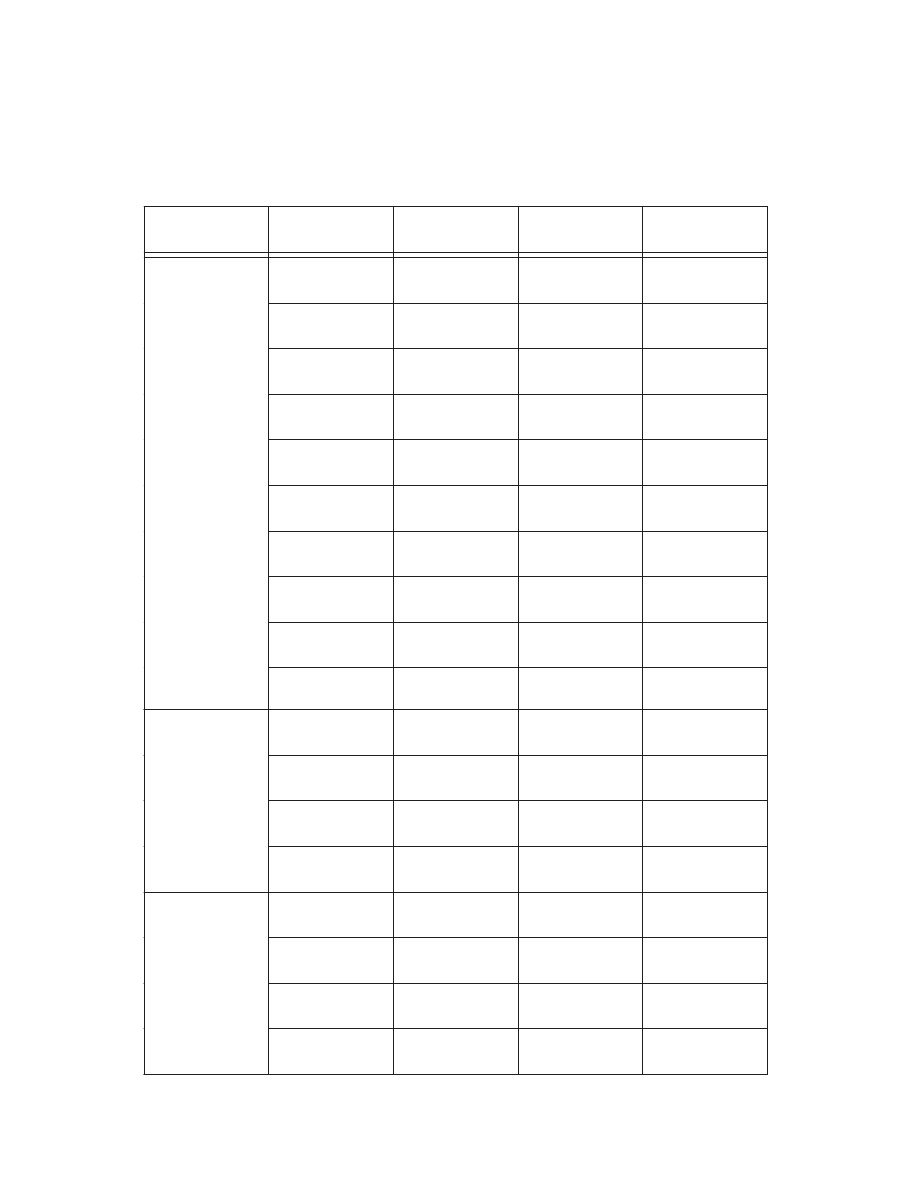
38 / DESIGN GUIDE 3, 2ND EDITION / SERVICEABILITY DESIGN CONSIDERATIONS FOR STEEL BUILDINGS
ROOFING
TYPE
STRUCTURAL
ELEMENT
DEFORMATION
RECOMMEN-
DATION
LOADING
ROOFING EXPAN-
SION JOINTS
HORIZONTAL
MOVEMENT
150’ TO 200’
MAXIMUM
THERMAL
METAL DECK
(TWO SPAN)
VERTICAL
DEFLECTION
L / 200
MAXIMUM
300-LB LOAD
METAL DECK
VERTICAL
DEFLECTION
L / 240
MAXIMUM
LL
METAL DECK
VERTICAL
DEFLECTION
L / 240
MAXIMUM
200-LB LOAD
METAL DECK
-
PER SDI TABLE
MAINTENANCE &
CONSTRUCTION
PURLINS
VERTICAL
DEFLECTION
PURLIN DEPTH ?
(F
y
/1000)
×
SPAN
-
STEEL JOISTS
VERTICAL
DEFLECTION
L / 240
MAXIMUM
LL
JOIST GIRDERS
VERTICAL
DEFLECTION
L / 240
MAXIMUM
LL
ROOF DECKS
VERTICAL
DEFLECTION.
L / 240
MAXIMUM
DL + DL
MEMBRANE
ROOFS
ROOFS
SLOPE
1 / 4 IN. PER FOOT
MINIMUM
DRAINAGE
EXPANSION
JOINTS
HORIZONTAL
MOVEMENT
100’ TO 200’
MAXIMUM
THERMAL
ROOF
SLOPE
1 / 2 IN. PER FOOT
MINIMUM
DRAINAGE
PURLIN
VERTICAL
DEFLECTION
L / 240
MAXIMUM
SNOW LOAD
METAL ROOFS
THROUGH
FASTENER TYPE
PURLIN
VERTICAL
DEFLECTION
POSITIVE
DRAINAGE
DL + 0.5
×
S
DL + 5 PSF
EXPANSION
JOINTS
HORIZONTAL
MOVEMENT
150’ TO 200’
MAXIMUM
THERMAL
ROOF
SLOPE
1 / 4 IN. PER FOOT
MINIMUM
DRAINAGE
PURLIN
VERTICAL
DEFLECTION
L / 150
MAXIMUM
SNOW LOAD
METAL ROOFS
STANDING SEAM
PURLIN
VERTICAL
DEFLECTION.
POSITIVE
DRAINAGE
DL + 0.5
×
S
DL + 5 PSF
SERVICEABILITY CONSIDERATIONS
ROOFING
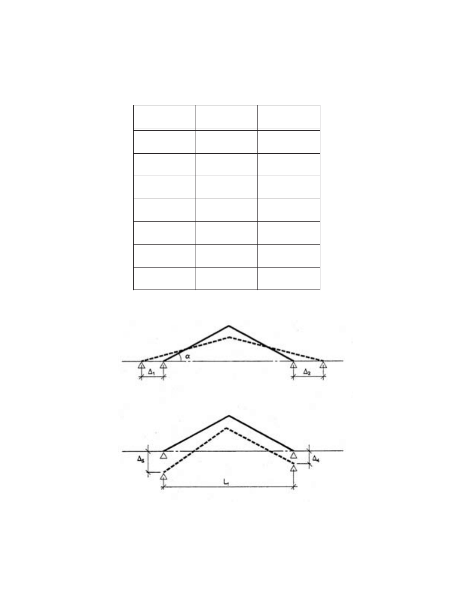
DESIGN GUIDE 3, 2ND EDITION / SERVICEABILITY DESIGN CONSIDERATIONS FOR STEEL BUILDINGS / 39
SERVICEABILITY CONSIDERATIONS
SKYLIGHT SUPPORTS
DEFORMATION
RECOMMEN-
DATION
LOADING
SKYLIGHT FRAME
RACKING
1 / 4 IN.
GASKETED
MULLIONS
DL + LL
SKYLIGHT FRAME
RACKING
1 / 8 IN.
FLUSH
GLAZING
DL + LL
DEFLECTION
NORMAL TO
GLAZING
L / 300
≤≤ 1 IN.
MAXIMUM
DL + LL
Ä1 + Ä2
± 1 / 8 IN.
α
? 25 DEGREES
DL + LL
Ä1 + Ä2
± 5 / 16 IN.
25
<<
α
<< 45 DEG.
DL + LL
Ä1 + Ä2
± 1 / 2 IN.
α
≥≥ 45 DEGREES
DL + LL
Ä3 - Ä4
L1 / 240 ≤
≤ 1 / 2 IN.
MAXIMUM
DL + LL
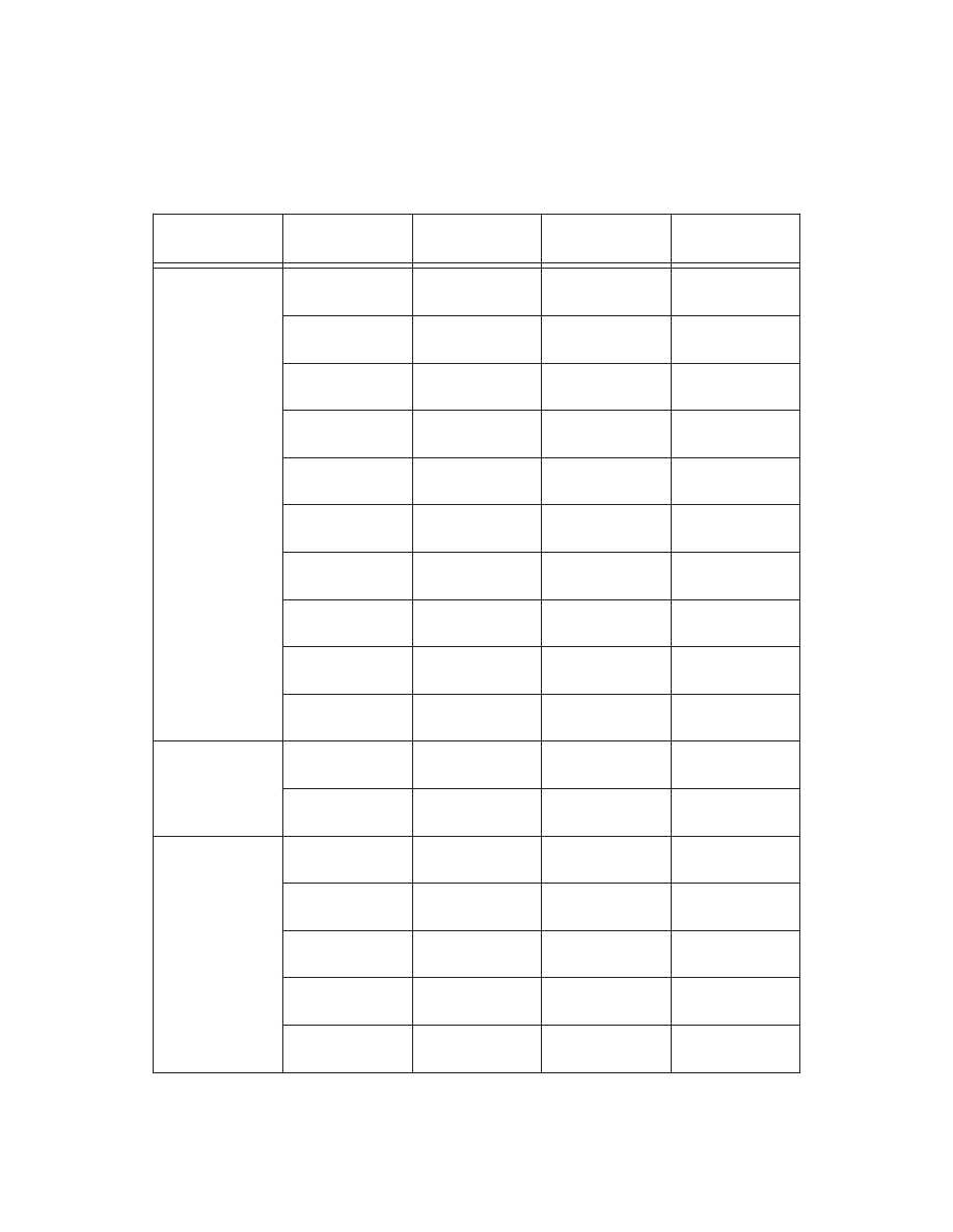
40 / DESIGN GUIDE 3, 2ND EDITION / SERVICEABILITY DESIGN CONSIDERATIONS FOR STEEL BUILDINGS
SERVICEABILITY CONSIDERATIONS
CLADDING
CLADDING
SUPPORT
TYPE
STRUCTURAL
ELEMENT
DEFORMATION
RECOMMEN-
DATION
LOADING
METAL PANELS /
BARE FRAME
DRIFT
PERPENDICULAR
TO WALL
H / 60 TO H/ 100
MAXIMUM
10 YEAR WIND
METAL PANELS /
GIRTS
HORIZONTAL
DEFLECTION
L / 120
MAXIMUM
10 YEAR WIND
METAL PANELS /
WIND COLUMNS
HORIZONTAL
DEFLECTION
L / 120
MAXIMUM
10 YEAR WIND
PRECAST WALLS /
BARE FRAME
DRIFT
PERPENDICULAR
TO WALL
H / 100
MAXIMUM
10 YEAR WIND
UNRIENFORCED
MASONRY WALLS /
BARE FRAME
DRIFT
PERPENDICULAR
TO WALL
1 / 16 IN. CRACK
BASE OF WALL
10 YEAR WIND
RIENFORCED
MASONRY WALLS /
BARE FRAME
DRIFT
PERPENDICULAR
TO WALL
H / 200
MAXIMUM
10 YEAR WIND
MASONRY WALLS /
GIRTS
HORIZONTAL
DEFLECTION
L / 240
≤≤ 1.5 IN.
MAXIMUM
10 YEAR WIND
MASONRY WALLS /
WIND COLUMNS
HORIZONTAL
DEFLECTION
L / 240
≤≤ 1.5 IN.
MAXIMUM
10 YEAR WIND
MASONRY WALLS /
LINTEL
VERTICAL
DEFLECTION
L / 600
≤≤ 0.3 IN.
MAXIMUM
DL + LL
FOUNDATION
MASONRY WALLS /
LINTEL
ROTATION
≤≤ 1 DEGREE
MAXIMUM
DL + LL
PRE-ASSEMBLED
UNITS / COLUMNS
RELATIVE
SHORTENING
1 / 4 IN.
MAXIMUM
0.5
×
LL
COLUMN
PRE-ASSEMBLED
UNITS / BARE
FRAME
RACKING
H / 500
10 YEAR WIND
CURTAIN WALLS /
BARE FRAME
RACKING
H / 500
10 YEAR WIND
CURTAIN WALLS /
SPANDRELS
VERTICAL
DEFLECTION
3 / 8 IN.
MAXIMUM
DL PRIOR TO
CLADDING
CURTAIN WALLS /
SPANDRELS
VERTICAL
DEFLECTION
L / 480
≤≤ 5 / 8 IN.
MAXIMUM
TOTAL DL
CURTAIN WALLS /
SPANDRELS
VERTICAL
DEFLECTION
L / 360
≤≤ 1 / 4 - 1 / 2 IN.
MAXIMUM
0.5
×
LL
SPANDREL
CURTAIN WALLS /
SPANDRELS
VERTICAL
DEFLECTION
L / 600
≤≤ 3 / 8 IN.
MAXIMUM
DL INCL.
CLADDING WEIGHT
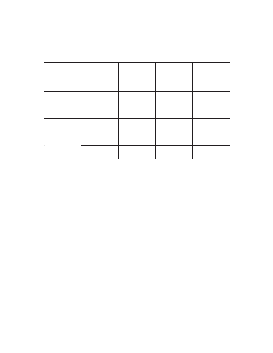
DESIGN GUIDE 3, 2ND EDITION / SERVICEABILITY DESIGN CONSIDERATIONS FOR STEEL BUILDINGS / 41
SERVICEABILITY CONSIDERATIONS
CEILINGS AND PARTITIONS
FINISH
TYPE
STRUCTURAL
ELEMENT
DEFORMATION
RECOMMEN-
DATION
LOADING
PLASTERED
CEILING
ROOF MEMBER
VERTICAL
DEFLECTION
L / 360
MAXIMUM
0.5
×
LL OR
50 YEAR SNOW
ROOF MEMBER
VERTICAL
DEFLECTION
L / 240
MAXIMUM
0.5
×
LL OR
50 YEAR SNOW
NON-PLASTERED
CEILING
FLOOR BEAM /
GIRDER
VERTICAL
DEFLECTION
L / 360
≤≤ 1 IN.
MAXIMUM
DL
FRAME
HORIZONTAL
MOVEMENT
H / 500
MAXIMUM
10 YEAR WIND
ROOF MEMBER
VERTICAL
DEFLECTION
3 / 8 IN. TO 1 IN.
MAXIMUM
0.5
×
LL OR
50 YEAR SNOW
PARTITION
FLOOR BEAM /
GIRDER
VERTICAL
DEFLECTION
L / 360
≤≤ 3 / 8 IN. TO
1 IN., MAXIMUM
0.5
×
LL
42 / DESIGN GUIDE 3, 2ND EDITION / SERVICEABILITY DESIGN CONSIDERATIONS FOR STEEL BUILDINGS
SERVICEABILITY CONSIDERATIONS
EQUIPMENT
EQUIPMENT
TYPE
STRUCTURAL
ELEMENT
DEFORMATION
RECOMMEN-
DATION
LOADING
RUNWAY
SUPPORTS
TOTAL INWARD
MOVEMENT
1 /2 IN.
MAXIMUM
LL OR
50 YEAR SNOW
RUNWAY
SUPPORTS
TOAL OUTWARD
MOVEMENT
1 IN.
MAXIMUM
SNOW
RUNWAY BEAM
HORIZONTAL
DEFECTION
L / 400
MAXIMUM
CRANE LATERAL
RUNWAY BEAM
CMAA ‘A’, ‘B’ & ‘C’
VERTICAL
DEFLECTION
L / 600
MAXIMUM
CRANE LATERAL
STATIC LOAD
RUNWAY BEAM
CMAA ‘D’
VERTICAL
DEFLECTION
L / 800
MAXIMUM
CRANE LATERAL
STATIC LOAD
TOP RUNNING
CRANES
RUNWAY BEAM
CMAA ‘E’ & ‘F’
VERTICAL
DEFLECTION
L / 1000
MAXIMUM
CRANE LATERAL
STATIC LOAD
TOP RUNNING
CAB OPERATED
BARE FRAME
DRIFT AT RUNWAY
ELEVATION
H / 100
≤≤ 1-IN.
MAXIMUM
CRANE LATERAL
OR 10 YR. WIND
TOP RUNNING
PENDANT
OPERATED
BARE FRAME
DRIFT AT RUNWAY
ELEVATION
H / 240
≤≤ 1-IN.
MAXIMUM
CRANE LATERAL
OR 10 YR. WIND
UNDERHUNG
CRANE
RUNWAY BEAM
CMAA ‘A’, ‘B’ & ‘C’
VERTICAL
DEFLECTION
L / 450
MAXIMUM
CRANE VERTICAL
JIB CRANE
BOOM
VERTICAL
DEFLECTION
H / 225
MAXIMUM
CRANE VERTICAL
BARE FRAME
DRIFT
H / 500
MAXIMUM
10 YEAR WIND
MACHINE /
SHEAVE BEAMS
VERTICAL
DEFLECTION
L / 1666
MAXIMUM
DL + LL
ELEVATORS
MACHINE /
SHEAVE BEAMS
SUPPORTS
VERTICAL
DEFLECTION
H / 1666
MAXIMUM
DL + LL
Wyszukiwarka
Podobne podstrony:
Core Wall Survey Control System for High Rise Buildings
Design Guide 10 Erection Bracing of Low Rise Structural Steel Frames
Lynge Odeon A Design Tool For Auditorium Acoustics, Noise Control And Loudspeaker Systems
AVR Hardware Design Considerations
Antisocial Guide To Horror Film The Essential Guide For Low Bud (2)
doc2521 AVR Hardware Design Considerations
Eurocode 6 Part 2 1996 2006 Design of Masonry Structures Design Considerations, Selection of Mat
AVR042 AVR Hardware Design Considerations
Eurocode 6 Part 2 1996 2006 Design of Masonry Structures Design Considerations, Selection of Mat
Design Requirements For Medium Sized Wind Turbines For Remote And Hybrid Power Systems
03 Service Specifications
ADVAC%20Tech%20Guide%2003 02
03 SERVICE SPECIFICATIONS
Best practice guide 03
więcej podobnych podstron