
WARNING
Servicing a vehicle can be dangerous. If you have not received
service-related training, the risks of injury, property damage, and
failure of servicing increase. The recommended servicing
procedures for the vehicle in this workshop manual were
developed with Mazda-trained technicians in mind. This manual
may be useful to non-Mazda trained technicians, but a technician
with our service-related training and experience will be at less
risk when performing service operations. However, all users of
this manual are excepted at least to know general safety
procedures.
This manual contains “Warnings” and “Cautions” applicable to
risks not normally encountered in a general technician’s
experience. They should be followed to reduce the risk of injury
and the risk that improper service or repair may damage the
vehicle or render it unsafe. It is also important to understand that
the “Warnings” and “Cautions” are not exhaustive. It is
impossible to warn of all the hazardous consequences that might
result from failure to follow the procedures.
The procedures recommended and described in this manual are
effective methods of performing service and repair. Some require
tools specifically designed for a specific purpose. Persons using
procedures and tools which are not recommended by Mazda
Motor Corporation must satisfy themselves thoroughly that
neither personal safety nor safety of the vehicle will be
jeopardized.
The contents of this manual, including drawings and
specifications, are the latest available at the time of printing, and
Mazda Motor Corporation reserves the right to change the vehicle
designs and alter the contents of this manual without notice and
without incurring obligation.
Parts should be replaced with genuine Mazda replacement parts
or with parts which match the quality of genuine Mazda
replacement parts. Persons using replacement parts of lesser
quality than that of genuine Mazda replacement parts must
satisfy themselves thoroughly that neither personal safety nor
safety of the vehicle will be jeopardized.
Mazda Motor Corporation is not responsible for any problems
which may arise from the use of this manual. The cause of such
problems includes but is not limited to insufficient service-
related training, use of improper tools, use of replacement parts
of lesser quality than that of genuine Mazda replacement parts, or
not being aware of any revision of this manual.
Mazda Motor Corporation
HIROSHIMA, JAPAN
APPLICATION:
This manual is applicable to vehicles beginning with
the Vehicle Identification Numbers (VIN) shown on
the following page.
© 2005 Mazda Motor Corporation
PRINTED IN THE NETHERLANDS. FEBRUARY 2005
5632-1E-05B
FOREWORD
This wiring diagram incorporates the wiring schematics
of the Mazda5 and available optional equipment. Actual
vehicle wiring may vary slightly depending on optional
equipment or local specifications, or both.
For proper repair and maintenance, a thorough
familiarization with this manual is important, and it
should always be kept in a handy place for quick and
easy reference.
All the contents of this manual, including drawings and
specifications, are the latest available at the time of
printing.
As modifications affecting repair or maintenance occur,
relevant information supplementary to this volume will be
made available at Mazda dealers. This manual should
be kept up-to-date.
Mazda Motor Corporation reserves the right to alter the
specifications and contents of this manual without
obligation or advance notice.
All rights reserved. No part of this book may be
reproduced or used in any form or by any means,
electronic or mechanical-including photocopying and
recording and the use of any kind of information storage
and retrieval system-without permission in writing.
CONTENTS
TITLE
SECTION
PREVIOUS
NEW
GENERAL INFORMATION
GI
(GENERAL INFORMATION)
00
W
(ELECTRICAL WIRING SCHEMATIC)
FB
(FUSE BLOCK)
JB
(JOINT BOX)
X
(COMMON CONNECTOR)
Y
(GROUND POINT)
S
Y
S
T
E
M
CI
RCU
IT
DIA
G
RAM/CONNE
C
T
O
R
LOCA
TI
ONS
U
(DATA LINK CONNECTOR)
ENGINE
A
(CHARGING SYSTEM/
STARTING SYSTEM)
01
B
(ENGINE CONTROL SYSTEM)
Q
(CRUISE CONTROL SYSTEM)
SUSPENSION
—
02
DRIVELINE/AXLE
—
03
BRAKES
O
(ANTI-LOCK BRAKE SYSTEM)
04
TRANSMISSION/
TRANSAXLE
H
(EC-AT CONTROL SYSTEM)
05
STEERING
N
(ELECTRIC POWER
STEERING SYSTEM)
06
HEATER, VENTILATION &
AIR CONDITIONING (HVAC)
G
(AIR CONDITIONING SYSTEM)
07
RESTRAINTS
S
(SEAT BELT/AIR BAG SYSTEM)
08
BODY & ACCESSORIES
C
(GAUGE CONTROL SYSTEM)
09
D
(WIPER SYSTEM)
E
(EXTERIOR LIGHTING SYSTEM)
F
(SIGNAL SYSTEM)
I
(INTERIOR LIGHTING SYSTEM)
J
(AUDIO SYSTEM)
K
(DOOR/WINDOW SYSTEM)
L
(MIRROR SYSTEM)
M
(SUNROOF SYSTEM)
P
(POWER SEAT SYSTEM)
T
(SECURITY AND LOCKS
SYSTEM/OPTION)
ALPHABETICAL INDEX
AI
(ALPHABETICAL INDEX)
AI
Wiring Diagram
Mazda5

VEHICLE IDENTIFICATION NUMBERS (VIN)
(CHASSIS NUMBERS)
JMZ CR1982*# 100001-
JMZ CR19F2*# 100001-
JMZ CR19F5*# 100001-

1
SYSTEM INDEX
R READING WIRING DIAGRAMS
VEHICLE IDENTIFICATION NUMBERS (VIN) CODE ....2
VEHICLE IDENTIFICATION NUMBERS (VIN)................2
CONTENTS OF WIRING DIAGRAMS ............................4
GROUND POINTS ..........................................................5
SYSTEM CIRCUIT DIAGRAM/
CONNECTOR DIAGRAM ..............................................6
ROUTING DIAGRAM ......................................................8
HARNESS SYMBOLS.....................................................9
WIRING COLOR CODE ..................................................9
SYMBOLS .....................................................................10
ABBREVIATIONS USED IN THIS MANUAL .................12
P ELECTRICAL SYSTEM GENERAL PROCEDURES......14
E ELECTRICAL WIRING SCHEMATIC ...........................18
F
FUSE BOX ....................................................................20
C COMMON CONNECTOR LIST .....................................22
G GROUND POINT...........................................................30
D DATA LINK CONNECTOR ............................................34
12 COOLING SYSTEM ......................................................38
14 FUEL SYSTEM .............................................................40
17 CHARGING SYSTEM ...................................................42
19 STARTING SYSTEM.....................................................44
40 CONTROL SYSTEM (INCLUDES AUTOMATIC
TRANSAXLE CONTROL INFORMATION) .................46
13 ANTILOCK BRAKE SYSTEM ......................................62
15 DYNAMIC STABILITY CONTROL (DSC) .....................64
18 AUTOMATIC TRANSAXLE SHIFT MECHANISM
KEY INTERLOCK SYSTEM ..........................................68
SHIFT-LOCK SYSTEM ..................................................68
14 POWER STEERING
ELECTRO HYDRAULIC POWER
ASSIST STEERING (EHPAS) SYSTEM .....................72
40 CONTROL SYSTEM
HEATER AND AIR CONDITIONER SYSTEM
AUTO A/C ...................................................................74
MANUAL A/C ..............................................................78
A/C COMPRESSOR CONTROL ...................................82
10 AIR BAG SYSTEM
AIR BAG SYSTEM SERVICE CAUTIONS/
SERVICE WARNINGS ................................................84
AIR BAG SYSTEM (INCLUDES PRE-TENSIONER
SEAT BELT INFORMATION) .......................................86
12 GLASS/WINDOWS/MIRRORS
REAR WINDOW DEFROSTER (INCLUDES
HEATED OUTER MIRROR INFORMATION).............. 92
POWER WINDOW SYSTEM ........................................ 94
POWER OUTER MIRROR ......................................... 102
13 SEATS
SEAT WARMER.......................................................... 104
14 SECURITY AND LOCKS
POWER DOOR LOCK SYSTEM
WITHOUT DOUBLE LOCKING SYSTEM................ 106
WITH DOUBLE LOCKING SYSTEM ....................... 110
IMMOBILIZER SYSTEM............................................. 114
KEYLESS ENTRY SYSTEM
WITHOUT ADVANCED KEYLESS SYSTEM ........... 116
WITH ADVANCED KEYLESS SYSTEM .................. 118
THEFT-DETERRENT SYSTEM.................................. 124
15 SUNROOF .................................................................. 128
18 LIGHTING SYSTEMS
HEADLIGHT ............................................................... 130
LICENSE PLATE LIGHT ............................................. 136
PARKING LIGHT......................................................... 136
TAILLIGHT .................................................................. 136
FRONT FOG LIGHT ................................................... 138
REAR FOG LIGHT...................................................... 140
BACK-UP LIGHT ........................................................ 142
BRAKE LIGHT ............................................................ 144
HIGH-MOUNT BRAKE LIGHT.................................... 144
TURN AND HAZARD WARNING LIGHT.................... 146
INTERIOR LIGHT ....................................................... 148
MAP LIGHT................................................................. 148
CARGO COMPARTMENT LIGHT............................... 150
ILLUMINATION LIGHT................................................ 152
HEADLIGHT MANUAL LEVELING SYSTEM ............. 158
HEADLIGHT AUTO LEVELING SYSTEM .................. 160
19 WIPER/WASHER SYSTEM
WINDSHIELD WIPER AND WASHER ....................... 162
REAR WIPER AND WASHER .................................... 168
HEADLIGHT CLEANER ............................................. 170
20 ENTERTAINMENT
ACCESSORY SOCKET .............................................. 172
CIGARETTE LIGHTER............................................... 172
AUDIO SYSTEM
WITHOUT CAR-NAVIGATION SYSTEM ................. 174
WITH CAR-NAVIGATION SYSTEM ......................... 178
REAR ENTERTAINMENT SYSTEM (RES) ................ 190
22 INSTRUMENTATION/DRIVER INFO.
INSTRUMENT CLUSTER........................................... 196
HORN ......................................................................... 206
INFORMATION DISPLAY ........................................... 208
40 CONTROL SYSTEM
BCM (BODY CONTROL MODULE)............................ 210
ALPHABETICAL INDEX ............................................. 218
00 GENERAL INFORMATION
POWER, GROUND & COMMON CONNECTOR
DATA LINK CONNECTOR
01 ENGINE
04 BRAKES
05 TRANSMISSION/TRANSAXLE
06 STEERING
07 HEATER, VENTILATION & AIR CONDITIONING
(HVAC)
08 RESTRAINTS
09 BODY & ACCESSORIES
AI ALPHABETICAL INDEX
Two digits (section ID) indicated in front of each title are commonly used with the Workshop Manual.
2
Reading Wiring Diagrams
00R
J M Z C R 1 9 8 2 5 # 1 2 3 4 5 6
for Europe-RHD: Dummy
for Europe-LHD: Dummy
for Others: Model year
Plant
Serial No.
0= Hiroshima
1= Hofu
0
5 to 9 (Same as model year-Israel etc.)
5= 2005
Transmission
2= 5MTX
5= 4ATX
6= 6MTX
Engine type
Body style
9= 4-door Station Wagon
Drive axle
1= FF
Vehicle type
CR= Mazda5
JMZ= European (L.H.D. U.K.)
World manufacturer identification
8= L8 (1.8 L)
F= LF (2.0 L)
T= RF-Turbo-Standard power (2.0 L)
R= RF-Turbo-High power (2.0 L)
VEHICLE IDENTIFICATION NUMBER (VIN) CODE

3
Reading Wiring Diagrams
00R
VEHICLE IDENTIFICATION NUMBERS (VIN)
JMZ CR1982*# 100001-
JMZ CR19F2*# 100001-
JMZ CR19F5*# 100001-
4
Reading Wiring Diagrams
00R
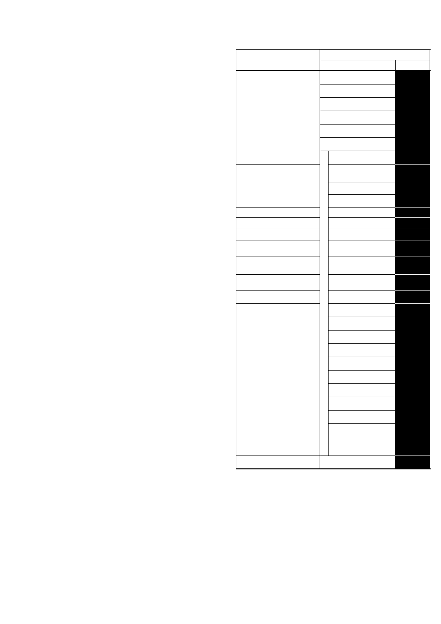
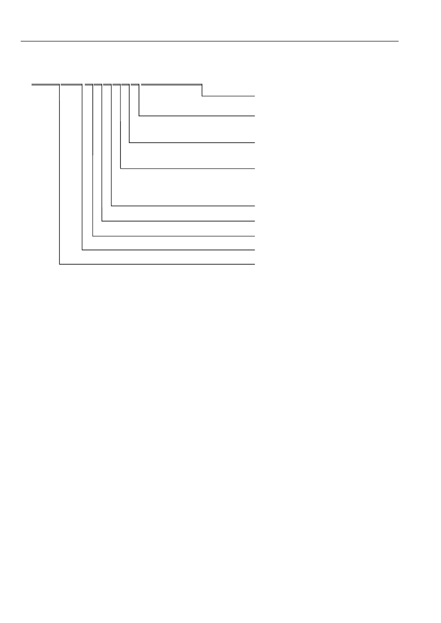
CONTENTS OF WIRING DIAGRAMS
• This manual comprises the sections shown below.
Depending on the vehicle model, the actual sections may be different.
NEW
PREVIOUS
GENERAL
INFORMATION
00
R Reading wiring diagrams
A how-to on using and reading
wiring diagrams, using test
equipment, checking harness
and connectors, and finding
trouble spots
GI
General information of
wiring diagrams
P
Electrical system general
procedures
E Electrical wiring schematic
Shows main fuses and other
fuses for each system
W Electrical wiring schematic
F
Fuse box complete wiring
system
Shows internal circuits and
connectors
FB
Fuse block complete
wiring system
J
Joint box/Junction box
complete wiring system
JB
Joint box complete wiring
system
C Common connector list
Shows connectors common
throughout system
X
Common connector list
G Ground point
Ground routes from and to the
battery
Y
Ground point
D Data link connector
Shows circuit and connector
diagrams and component and
connector location diagrams
U Data link connector
ENGINE
01
12 Cooling system
A
Charging system/Starting
system
14 Fuel system
17 Charging system
B
Engine control system
18 Ignition system
C
Gauge control system
19 Starting system
D
Wiper system
20 Cruise control system
E
Lighting system
40 Control system
F
Signal system
SUSPENSION
02
12 Wheel and tires
G
Air-conditioning system
DRIVELINE/AXLE
03
18 4-Wheel drive
BRAKES
04
13 Antilock brake system
H
Transmission control/Key
interlock/Shift-lock system
14 Traction control system
15 Dynamic stability control
I
Interior light system
TRANSMISSION/
TRANSAXLE
05
13 Automatic transmission
14
Automatic transmission shift
mechanism
J
Audio/Radio system
17 Automatic transaxle
18
Automatic transaxle shift
mechanism
K
Power window/Power door
lock system
STEERING
06
13 Electric power steering (EPS)
14 Power steering
HEATER,
VENTILATION &
AIR
CONDITIONING
(HVAC)
07
40 Control system
L
Remote control mirror
system
RESTRAINTS
08
10 Air bag system
11 Seat belt
M
Sliding sunroof system
BODY &
ACCESSORIES
09
12 Glass/Windows/Mirrors
O
Anti-lock brake system
13 Seats
14 Security and locks
N
Electric power steering
(EPS)
15 Sunroof
18 Lighting systems
P
Power seat/Seat warmer
system
19 Wiper/Washer system
20 Entertainment
Q
Auto cruise control
system
21 Power systems
22 Instrumentation/Driver info.
S
Air bag system
40 Control system
T
Others
AI
Alphabetical Index
Gives page number of circuit
diagram for each component
AI Alphabetical Index
5
Reading Wiring Diagrams
00R
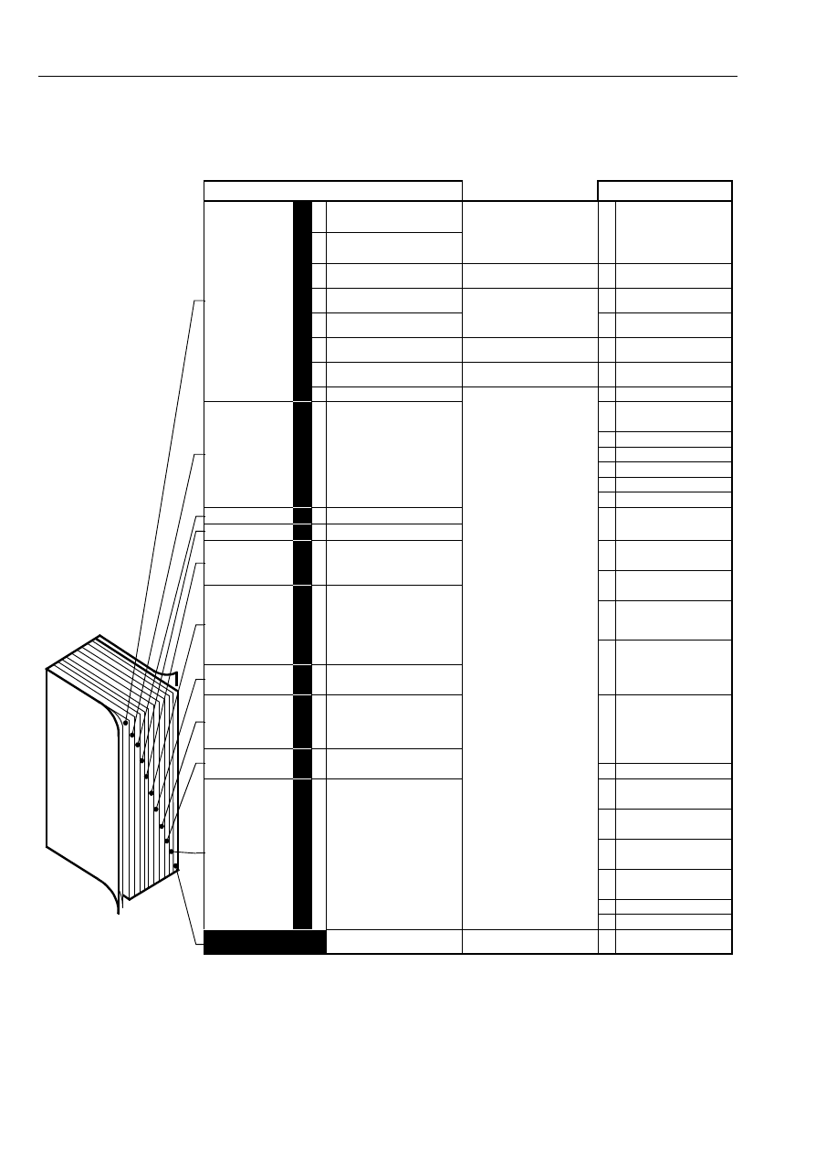
GROUND POINTS
• This shows ground points of the harness.
On circuit diagrams and ground points
The ground connection numbers in system circuit diagrams
correspond to those in the ground point diagram.
Ground indication
On vehide
Indication
To circuit
GROUND POINTS (4SD)
EMISSION
HARNESS
(EM)
TO
EACH
UNIT
(WITH AIR BAG SYSTEM)
G-01 JOINT CONNECTOR(F)
G-02 JOINT CONNECTOR(F)
(WITHOUT AIR BAG SYSTEM)
G-03 JOINT CONNECTOR(D)
FRONT
HARNESS
(F)
TO
EACH
UNIT
G-02
B(F)
B(F)
B(F)
B
(F)
1
B(F)
G-01
B(F)
B(F)
B(F)
B(F)
B(F)
B(F)
B(F)
B(F)
2
SHORT
CORD
TO
EACH
UNIT
G-03
WITHOUT AIR BAG SYSTEM
10
B(D)
B(D)
B(D)
B(D)
B(D)
B(D)
B(D)
B(D)
9
B(D)
11
B/W(EM)
B(EM)
6
B(EM)
4
B(EM)
5
B(EM)
B(EM)
4
B(I)
8
B(I)
9
B(D)
3
WITH AIR BAG SYSTEM
B/O(D)
3
B(IN)
7
INSTRUMENT
PANEL
HARNESS
(I)
DASH
HARNESS
(D)
INTERIOR
LIGHT
HARNESS
(IN)
9
8
12
4
7
5
B
B
B
B
B/W
6
4
B(I)
10
B/O
B
B
B
B
B
B
B
E
D
B
A
E
D
C
B
A
C
WITH ABS
3
3
12
5
B(EM)
B
B
E
D
B
A
E
D
C
B
A
C
B
B
B
B
B
B
B
B
E
D
B
A
E
D
C
B
A
C
B
B
B
B
B
B
E
D
B
A
E
D
C
B
A
C
B
B
B
B
B
MAIN
100A
INJ OR
FIP
30A
IG KEY
60A
BTN
40A
ROOM
10A
ENGINE
10A
-
+
BATTERY
CONTROL SYSTEM
PCM
B(E)
F-03
LG/R
(EM)
0140-101
0140-103
0140-102
1E
L/R(E)
0140-104
GLOW
PLUG
B
B
(EM)
C-09
L/R(EM)
J-04
F
ST
IG2
ACC
OFF
IG1
C-03
C-03
B/L(D)
3W
0140-103
L/R
B
B/W
L
(E)
B(D)
0140-102
B
(E)
U
W/Y
(EM)
B(F)
C-01
B/W(D)
I
F-03
Y/L(F)
F-04
Y
B/W
(F)
MAIN RELAY
F-07
D
B/W(F)
W/G(EM)
F-03
T
F-04
S
F-05
A
1B
F-04
G
GLOW
PLUG
RELAY
B/L
(EM)
1A
J-01
H
L(D)
C-09
C-06
F-09
A
5
1U
1V
1C
1E
1G
1I
1K
1M
1O
1Q
1S
1A
1B
1D
1F
1H
1J
1L
1N
1P
1R
1T
2O
2P
2C
2E
2G
2I
2K
2M
2A
2B
2D
2F
2H
2J
2L
2N
3C
3E
3G
3I
3K
3M
3O
3Q
3S
3U
3W
3Y
3Z
3X
3V
3T
3R
3P
3N
3L
3J
3H
3F
3D
3A
3B
0140-101
Y
W/G
W/L
L/B
P/L
L/W
L/R
V/W
B/L
G/W
LG/R
R/Y
V
W/Y
L/R
G/R
R
L
LG/B BR/W R/L
R/Y
GY/R
O
L/Y
BR/Y
L/W
P/B
B/W
L/R
R/L
LG
V
R
B
B/O
L
W
G
G/R
Y/B
BR/B
G/Y
0140-105
0140-105
14
0140-104
B
L
B
(E)
(SHORT CORD)
B
1B
AA
ENGINE SWITCH
D
G
W/R(F)
W/R(D)
1F
L/R
(EM)
L/R
(D)
J-05
J-03
A
J
8
C-06
L
(E)
L(E)
F-01
F-03
V
I
0140-101
L
(EM)
2M
SPV RELAY
(SECTION 0140-1b)
2
W/R
1S
G/B
(EM)
11
A/C RELAY
(SECTION 0740-2)
3R
LG
(EM)
14
REFRIGERANT
PRESSURE SWITCH
(SECTION 0740-1)
23
3P
BR/B
(EM)
22
DATA LINK CONNECTOR(DLC)
(SECTION 00D)
1N
G/W
(EM)
31
AD FAN RELAY
(SECTION 0740-2)
L/B
(EM)
1Q
R/B
0140-102
L
J
PCM(EM)
GLOW PLUG RELAY(F)
GLOW PLUG(SHORT CORD)
ENGINE(E)-SHORT CORD
GLOW PLUG RELAY(E)
6
Reading Wiring Diagrams
00R
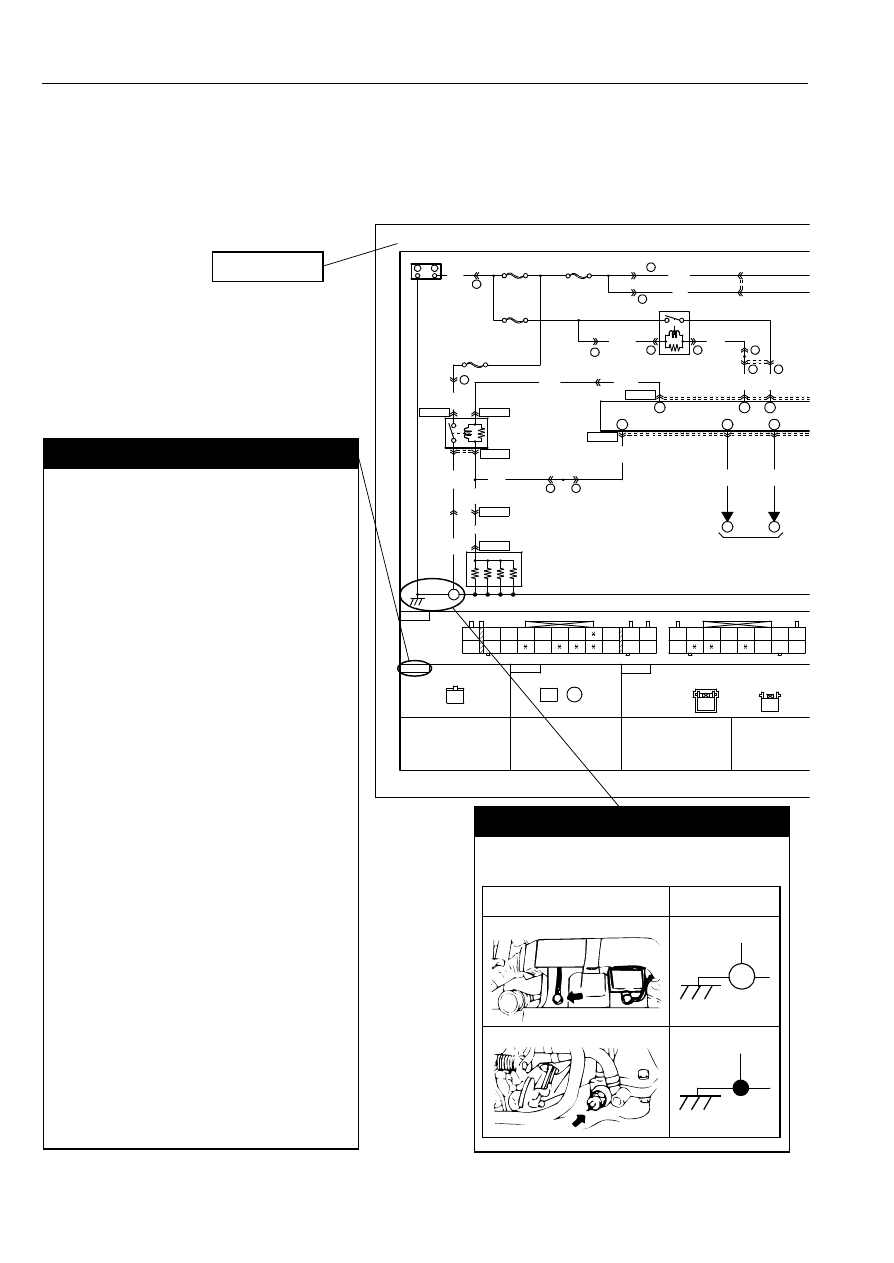
Ground numbers
A harness ground is represented differently than a
unit ground.
Types of grounds
Symbol
Harness
Unit
9
Sensor
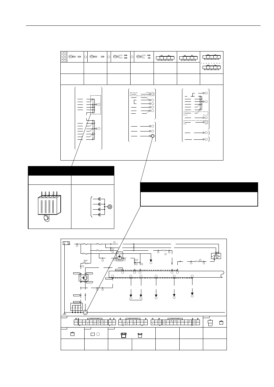
SYSTEM CIRCUIT DIAGRAM/CONNECTOR DIAGRAM
• These diagrams show the circuits for each system, from the power supply to the ground. The power supply side
is on the upper part of the page, the ground side on the lower part. The diagrams describe circuits with the
ignition switch off.
Below is an explanation of the various points in the diagram.
System name
MAIN
100A
INJ OR
FIP
30A
IG KEY
60A
GLOW
40A
W/Y
-
+
BATTERY
B(E)
F-03
LG/R
(EM)
0140-101
0140-103
0140-102
1E
L/R(E)
0140-104
GLOW
PLUG
B
B
(EM)
C-09
L/R(EM)
3W
0140-103
B/W
B
(E)
0140-102
L
(E)
U
W/Y
(EM)
B(F)
C-01
I
F-03
Y/L(F)
F-04
Y
B/W
(F)
MAIN RELAY
F-07
D
B/W(F)
W/G(EM)
F-03
T
F-04
S
F-05
1B
F-04
G
GLOW
PLUG
RELAY
C-09
F-09
A
5
1U
1V
1C
1E
1G
1I
1K
1M
1O
1Q
1S
1A
1B
1D
1F
1H
1J
1L
1N
1P
1R
1T
2O
2P
2C
2E
2G
2I
2K
2M
2A
2B
2D
2F
2H
2J
2L
2N
0140-101
Y
W/G
W/L
L/B
P/L
L/W
L/R
V/W
B/L
G/W
LG/R
R/Y
G/Y W/Y
R/W
G/R
R
L
LG/B BR/W R/L
R/Y
GY/R
O
L/Y
BR/Y
L/W
P/B
0140-105
0140-105
0140-104
B
L
B
(E)
(SHORT CORD)
B
D
G
L(E)
F-01
F-03
V
I
0140-101
L
(EM)
2M
W/R
3R
LG
(EM)
23
3P
BR/B
(EM)
22
DATA LINK CONNECTOR(DLC)
(SECTION 00D)
J
CONTROL SYSTEM
GLOW PLUG RELAY(F)
PCM(EM)
GLOW PLUG(SHORT CORD)
ENGINE(E)-SHORT CORD
Connector code
The prefix letter indicates the system in which the
connector is used.
F: Fuse box connectors
J: Joint box/Junction box connectors
C: Common connectors
G: Ground point connectors
D: Data link connector
0112: Cooling system connectors
0114: Fuel system connectors
0117: Charging system connectors
0118: Ignition system connectors
0119: Starting system connectors
0120: Cruise control system connectors
0140: Engine control system connectors
0212: Wheel and tires connectors
0318: 4-Wheel drive connectors
0413: Antilock brake system connectors
0414: Traction control system connectors
0415: Dynamic stability control connectors
0513: Automatic transmission connectors
0514: Automatic transmission shift mechanism
connectors
0517: Automatic transaxle connectors
0518: Automatic transaxle shift mechanism
connectors
0613: Electric power steering (EPS) connectors
0614: Power steering connectors
0740: Heater, ventilation & air conditioning (HVAC)
control system connectors
0810: Air bag system connectors
0811: Seat belt connectors
0912: Glass/Windows/Mirrors connectors
0913: Seats connectors
0914: Security and locks connectors
0915: Sunroof connectors
0918: Lighting systems connectors
0919: Wiper/Washer system connectors
0920: Entertainment connectors
0921: Power systems
0922: Instrumentation/Driver info. Connectors
0940: Control system
7
Reading Wiring Diagrams
00R
ENGINE
10A
16
1D
G/Y
(EM)
A
1I
W/Y
(EM)
B
1A
R/W
(EM)
DATA LINK
CONNECTOR(DLC)
(SECTION 00D)
0140-106
O
P/B GY/R
O
(EM)
GY/R
(EM)
P/B
(EM)
2A
BOOST SENSOR
2C
0140-106
2B
R/Y
(EM)
INTAKE AIR
TEMPERATURE
SENSOR NO.1
2E
O
(EM)
0140-107
0140-107
0140-107
R/Y
O
B
(EM)
4
SHIELD WIRE
PCM
J-04
F
ST
IG2
ACC
OFF
IG1
C-03
C-03
B/L(D)
L/R
B
B(D)
B/W(D)
B/L
(EM)
J-01
H
L(D)
C-06
3C
3E
3G
3I
3K
3M
3O
3Q
3S
3U
3W
3Y
3Z
3X
3V
3T
3R
3P
3N
3L
3J
3H
3F
3D
3A
3B
B/W
L/R
R/L
LG
V
R
B
B/O
L
W
G
G/R
Y/B
BR/B
G/Y
14
1B
AA
ENGINE SWITCH
1F
1S
W/R
(EM)
14
REFRIGERANT
PRESSURE SWITCH
(SECTION 0740-1)
R/B
0140-102
L
0140-101
0140-1a
GLOW PLUG RELAY(E)
BOOST SENSOR(EM)
INTAKE AIR TEMPERATURE SENSOR NO.1(EM)
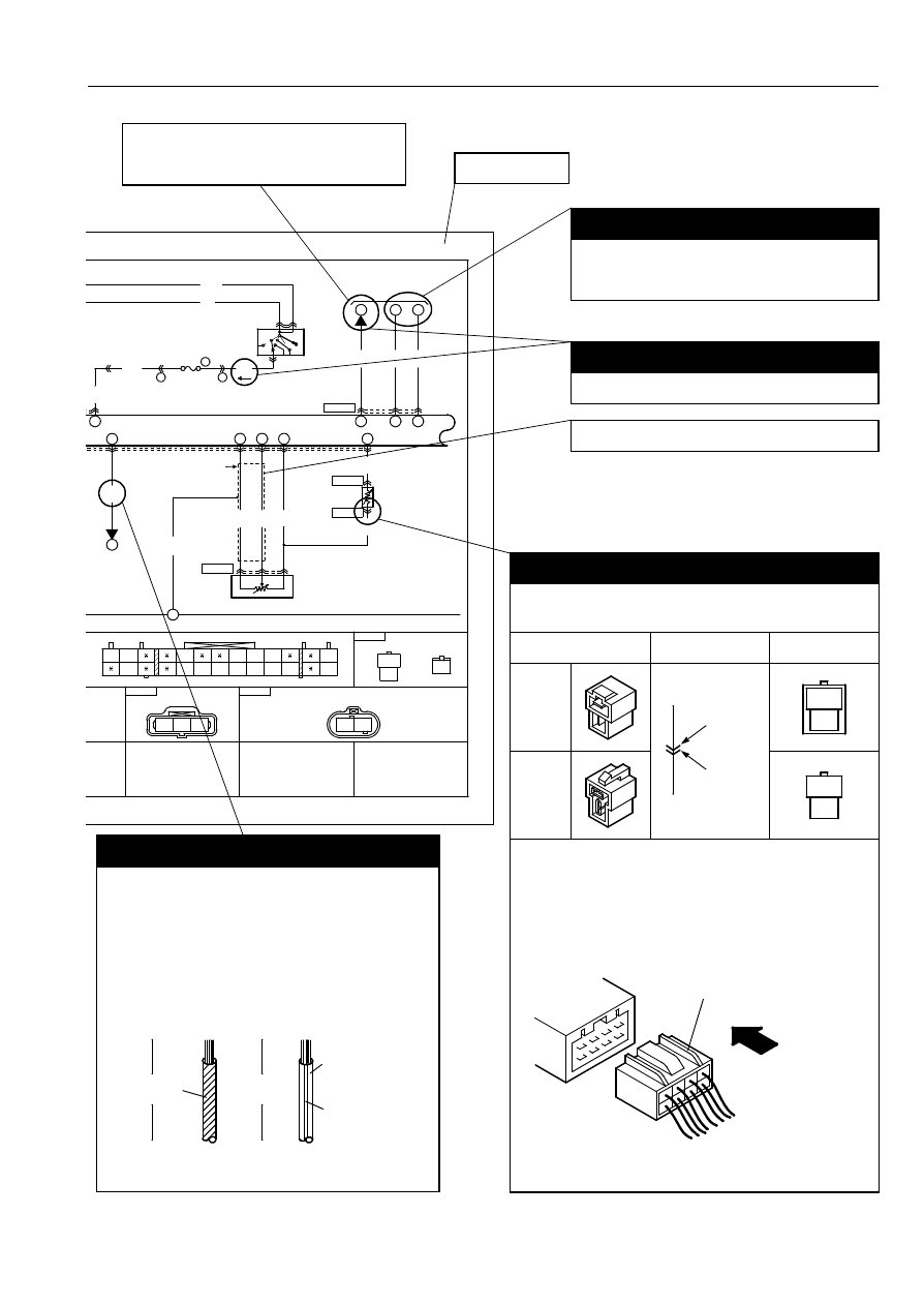
Wire color code (harness symbol)
•
Two-color wires are indicated by a two-letter
symbol.The first indicates the base color of the
wire, the second the color of the stripe.
For example:
W/R is a white wire with a red strip
BR/Y is a brown wire with a yellow strip
Symbol
(Example)
•
The harness symbol is in ( ) following the harness
symbols (refer to P-9.).
Solid color wire
Striped wire
B
(F)
W/R
(F)
White
(base color)
Red(stripe)
Black
Connector symbols
•
Male and female connectors are represented as follows
in the circuit and connector diagrams.
Circuit diagram
symbol
Connector
diagram symbol
Male
Female
•
Like connectors are linked by dashed lines between the
connector symbols.
•
Connector diagrams show connectors on the harness
side. The terminal indicates the view from the harness
side.
(Example)
•
Colors for connectors except white are given in locations.
•
Unused terminals are indicated by
∗
.
Male
Female
L
R
L
R
Connector on harness side
View from harness side
Current symbol
Current flows in the direction of the arrow.
Indicates shielded wire.*
The number indicates that the circuit
continues to the related system
diagram.
System code
* Shielded wire :
Prevents signal disturbances from
electrical interference.
Wire is covered by a metal meshing for
grounding.
Multiplex communication
Indicates communication with connected parts.
Signals are transmitted back and forth between
connected parts.
8
Reading Wiring Diagrams
00R
Connector symbol
Shows the system that uses the
connector.
(Example)
Connector
Symbol
Common connectors
C-02
System connectors
0922-05
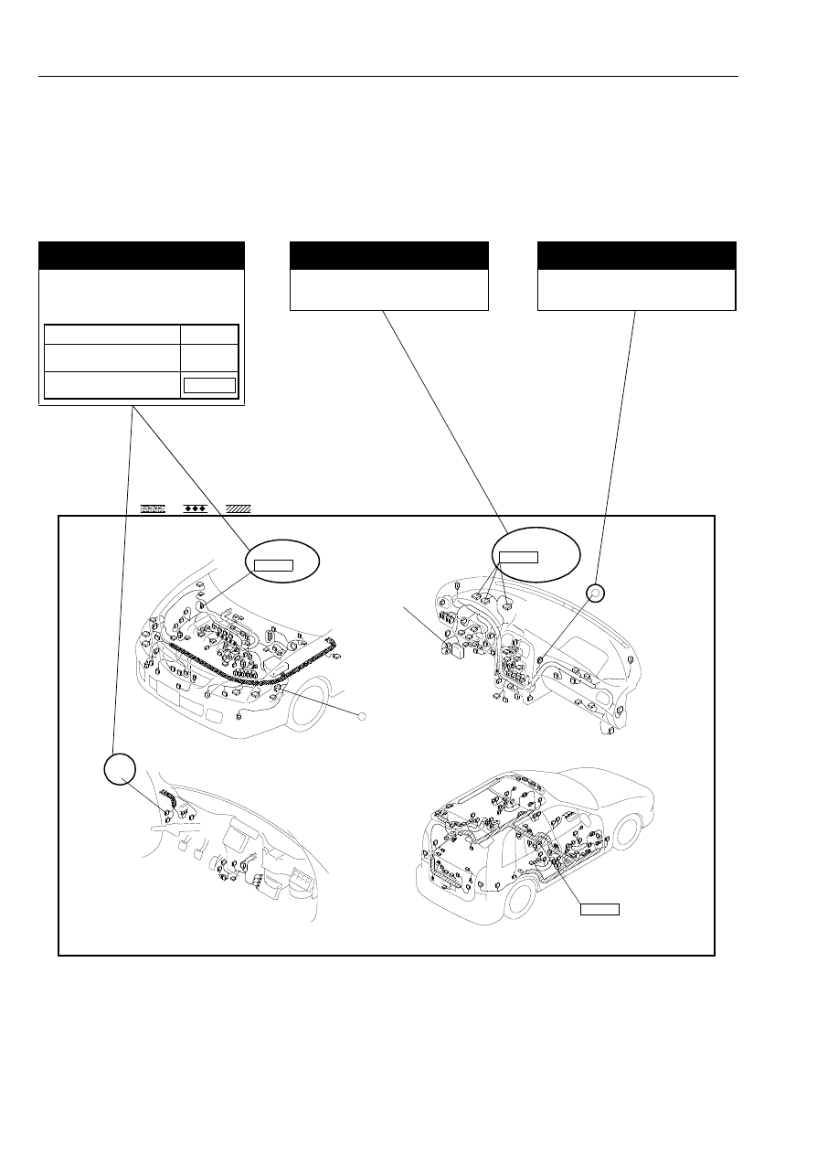
ROUTING DIAGRAM
• The routing diagram shows where electrical components are on the system circuit diagram by call out line and
connector symbols.
Ground symbol
Shows the ground in system
diagrams.
Component name
Shows the names of components
in routing diagrams.
1
HARNESS SYMBOL :
(F)
(R)
(E)
6
(F)-(I)
C-02
INSTRUMENT CLUSTER
0922-01
(F)-(I)
C-02
VACUUM SWITCH
0922-05
PARKING BRAKE SWITCH
0922-06
9
Reading Wiring Diagrams
00R
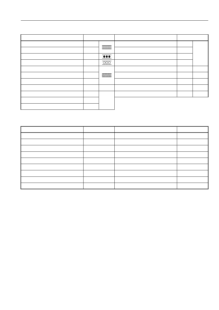
HARNESS SYMBOLS
DESCRIPTION OF HARNESS
SYMBOL
DESCRIPTION OF HARNESS
SYMBOL
FRONT HARNESS
(F)
DOOR No. 1 HARNESS
(DR1)
—
FRONT No. 2 HARNESS
(F2)
DOOR No. 2 HARNESS
(DR2)
ENGINE HARNESS
(E)
DOOR No. 3 HARNESS
(DR3)
DASH HARNESS
(D)
DOOR No. 4 HARNESS
(DR4)
REAR HARNESS
(R)
FLOOR HARNESS
(FR)
—
REAR No. 2 HARNESS
(R2)
INTERIOR LIGHT HARNESS
(IN)
—
REAR No. 3 HARNESS
(R3)
A/C HARNESS
(AC)
—
INSTRUMENT PANEL HARNESS
( I )
—
INJECTION HARNESS
(INJ)
—
EMISSION HARNESS
(EM)
—
HAND BRAKE HARNESS
(HB)
—
EMISSION No. 2 HARNESS
(EM2)
EMISSION No. 3 HARNESS
(EM3)
WIRING COLOR CODE
COLOR
CODE
COLOR
CODE
BLACK
B
ORANGE
O
BLUE
L
PINK
P
BROWN
BR
RED
R
DARK BLUE
DL
SKY BLUE
SB
DARK GREEN
DG
TAN
T
GRAY
GY
VIOLET
V
GREEN
G
WHITE
W
LIGHT BLUE
LB
YELLOW
Y
LIGHT GREEN
LG
10
Reading Wiring Diagrams
00R
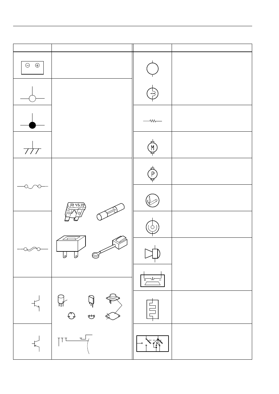
SYMBOLS
Symbol
Meaning
Symbol
Meaning
Battery
• Generates electricity through chemical
reaction.
• Supplies direct current to circuits.
Light
– – – – – – – – – – – – – – –
• Emits light and generates heat when
current flows through filament.
Ground (1)
• Connecting point to vehicle body or
other ground wire where current flows
from positive to negative terminal of
battery.
• Ground (1) indicates a ground point to
body through wire harness.
• Ground (2) indicates point where
component is grounded directly to
body.
Remarks
• Current will not flow through a circuit if
ground is faulty.
Ground (2)
Resistance
• A resistor with a constant value.
• Mainly used to protect electrical
components in circuits by maintaining
rated voltage.
Ground (3)
Motor
• Converts electrical energy into
mechanical energy.
Fuse
• Melts when current flow exceeds that
specified for circuit, interrupts current
flow.
Precautions
• Do not replace with fuses exceeding
specified capacity.
Pump
• Pulls in and discharges gases and
liquids.
Cigarette lighter
• Electrical coil that generates heat.
Fuse (For high
current fuse)/
Fusible link
Accessory socket
• Interior power supply.
Horn
• Generates sound when current flows.
Speaker
Transistor (1)
• Electrical switching component.
• Turns on when voltage is applied to
the base (B).
Heater
• Generates heat when current flows.
Transistor (2)
• Reading code.
Ignition switch
• Turning ignition key switches circuit to
operate various component.
(NOTE)
Ignition switch is called engine switch
on diesel vehicles.
3.4W
1
<Blade type>
<Cartridge type>
<Fusible link>
<Tube type>
Collector (C)
Base (B)
NPN
Emitter (E)
C
E
B
C
E B
C
E
B
Collector
indication
mark
Collector (C)
Base (B)
PNP
Emitter (E)
2 S C 828 A
A:High-frequency PNP
B:Low-frequency PNP
C:High-frequency NPN
D:Low-frequency NPN
Number of
terminals
Semiconductor
Revision mark
O F F
B 2
B 1
S T
IG 2
A C C
O F F
IG 1
11
Reading Wiring Diagrams
00R
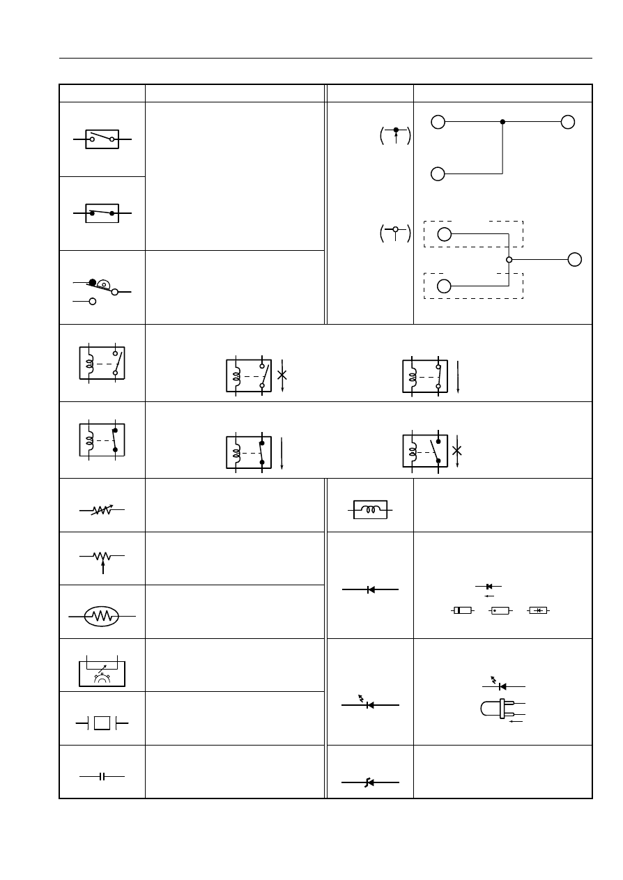
Symbol
Meaning
Symbol
Meaning
Switch (1)
Normally open
• Allows or breaks current flow by
opening and closing curcuits.
Harness
Connection
When circuit C-D
is connected to
circuit A-B, the
connection D is
indicated by a
black dot.
Selection
Diversion point D
for the different
circuits according
to the vehicle’s
specification is
indicated by a
white dot.
For vehicles with ABS, use the A-B
circuit.
For vehicles without ABS, use the C-B
circuit.
Switch (2)
Normally closed
Autostop switch
• Automatically shuts off circuit when
certain conditions are met.
Relay (1)
Normally open
• Current flowing through coil produces electromagnetic force causing contact to open or close.
Relay (2)
Normally closed
• Current flowing through coil produces electromagnetic force causing contact to close.
Sensor (1)
• Detects characteristics such as intake
manifold vacuum and airflow amount
according to resistance variation.
Solenoid
• Current flowing through coil generates
electromagnetic force to operate
plungers.
Sensor (2)
• Detects resistance variation according
to operation of other parts.
Diode
• Known as a semiconductor rectifier,
the diode allows current flow in one
direction only.
Sensor (3)
• A resistor whose resistance variation
according to temperature variation.
• When temperature increases,
resistance decreases.
Sensor (4)
• Detects pulse signals from rotating
object.
Light-emitting
diode
(LED)
• A diode that lights when current flows.
• Unlike ordinary bulbs, the diode does
not generate heat when lit.
Sensor (5)
• Generates potential difference when
tension or pressure is applied.
Capacitor
• Component that temporarily stores
electrical charge.
Reference diode
(Zener diode)
• Allows current to flow in one direction
up to a certain voltage; allows current
to flow in the other direction once that
voltage is exceeded.
A
C
D
B
A
C
D
B
WITHOUT ABS
WITH ABS
Flow
No flow
No current to coil
Current to coil
No flow
Flow
No current to coil
Current to coil
A
K
A
K
K
A
Anode(A)
Flow of electric current
Cathode(K)
Anode(A)
Cathode(K)
Anode(A)
Cathode(K)
Flow of current
12
Reading Wiring Diagrams
00R
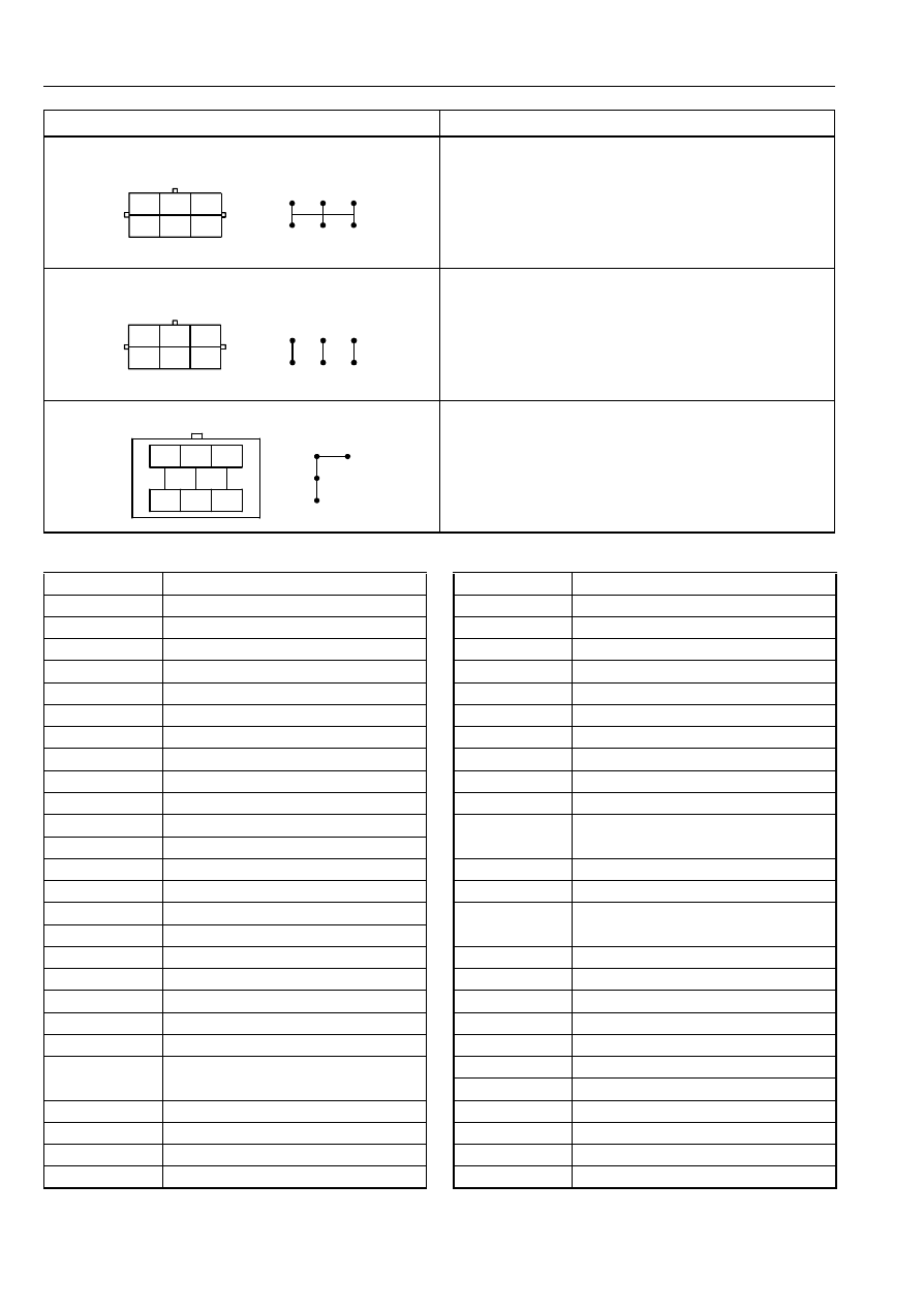
Symbol
Meaning
Extent of the change in the wiring position (1)
• The wiring position can be exchanged freely within the
connector.
Extent of the change in the wiring position (2)
• The wiring position can be exchanged according to the
following combinations only.
Between A and B, Between C and D, Between E and F
Extent of the change in the wiring position (3)
• The wiring position can be exchanged according to the
following combinations only.
Between 1, 2, 4 and 7.
• The wiring positions may be indicated by numbers for some
connectors.
C
A
E
D
B
F
C
A
E
D
B
F
B
B
B
B
B
B
C
A
E
D
B
F
C
A
E
D
B
F
B
B
B
B
B
B
3
5
8
2
4
7
1
6
R
L
L
B
B
B
B
B/Y
2
4
7
1
ABBREVIATIONS USED IN THIS MANUAL
3GR
THIRD GEAR
4GR
FOURTH GEAR
A
AMPERE
A/C
AIR CONDITIONING
A/F
AIR FUEL
AAS
AUTO ADJUSTING SUSPENSION
ABS
ANTI-LOCK BRAKING SYSTEM
ACC
ACCESSORIES
ACV
AIR CONTROL VALVE
ADD
ADDITIONAL
AIS
AIR INJECTION SYSTEM
ALL
AUTOMATIC LOAD LEVELING
AM
AMPLITUDE MODULATION
AMP
AMPLIFIER
ANT
ANTENNA
ASV
AIR SUPPLY VALVE
AT
AUTOMATIC TRANSMISSION
ATX
AUTOMATIC TRANSAXLE
B+
BATTERY POSITIVE VOLTAGE
BAC
BYPASS AIR CONTROL
CAN
CONTROLLER AREA NETWORK
CIGAR
CIGARETTE
CIS
CONTINUOUS FUEL INJECTION
SYSTEM
CKP
CRANKSHAFT POSITION SENSOR
CM
CONTROL MODULE
CMP
CAMSHAFT POSITION SENSOR
COMBI
COMBINATION
CON
CONDITIONER
CONT
CONTROL
CPU
CENTRAL PROCESSING UNIT
DEF
DEFROSTER
DI
DISTRIBUTOR IGNITION
DLC
DATA LINK CONNECTOR
DLI
DISTRIBUTORLESS IGNITION
DOHC
DOUBLE-OVERHEAD CAMSHAFT
DRL
DAYTIME RUNNING LIGHT
DTC
DIAGNOSTIC TROUBLE CODE(S)
DTM
DIAGNOSTIC TEST MODE
ECPS
ELECTRONICALLY CONTROLLED
POWER STEERING
ECT
ENGINE CONTROL TEMPERATURE
EGR
EXHAUST GAS RECIRCULATION
EHPAS
ELECTRO HYDRAULIC POWER
ASSIST STEERING
EI
ELECTRONIC IGNITION
ELEC
ELECTRIC
ELR
EMERGENCY LOCKING RETRACTOR
ET
ELECTRONIC THROTTLE
EPS
ELECTRIC POWER STEERING
EVAP
EVAPORATIVE EMISSION
F
FRONT
F/I
FUEL INJECTOR
FICB
FAST-IDLE CAM BREAKER
FM
FREQUENCY MODULATION
FP
FUEL PUMP

13
Reading Wiring Diagrams
00R
FPR
FUEL PUMP RELAY
GEN
GENERATOR
GND
GROUND
H/D
HEATER/DEFROSTER
HEAT
HEATER
HI
HIGH
HO2S
HEATED OXYGEN SENSOR
HS
HIGH SPEED
HU
HYDRAULIC UNIT
IAC
IDLE AIR CONTROL
IAT
INTAKE AIR TEMPERATURE
IG
IGNITION
ILLUMI
ILLUMINATION
INT
INTERMITTENT
JB
JOINT BOX
KS
KNOCK SENSOR
LCD
LIQUID CRYSTAL DISPLAY
LF
LEFT FRONT
LH
LEFT HAND
LO
LOW
LR
LEFT REAR
M
MOTOR
MAF
MASS AIR FLOW
MAP
MANIFOLD ABSOLUTE PRESSURE
MFI
MULTIPORT FUEL INJECTION
MID
MIDDLE
MIL
MALFUNCTION INDICATOR LAMP
MIN
MINUTE
MIX
MIXTURE
MPX
MULTIPLEX
MS
MIDDLE SPEED
MT
MANUAL TRANSMISSION
MTX
MANUAL TRANSAXLE
N
NEUTRAL
NC
NORMALLY CLOSED
NO
NORMALLY OPEN
O2S
OXYGEN SENSOR
OBD
ON-BOARD DIAGNOSTIC
O/D
OVER DRIVE
OFF
SWITCH OFF
ON
SWITCH ON
OSC
OSCILLATOR
P
POWER
P/S
POWER STEERING
PCM
POWERTRAIN CONTROL MODULE
PJB
PASSENGER JUNCTION BOX
PNP
PARK/NEUTRAL POSITION
PRC
PRESSURE REGULATOR CONTROL
PRG
PURGE SOLENOID VALVE
PSP
POWER STEERING PRESSURE
PTC
POSITIVE TEMPERATURE
COEFFICIENT HEATER
PWM
PULSE WIDTH MODULATION
QSS
QUICK-START SYSTEM
R
REAR
REC
RECIRCULATION
RES
REAR ENTERTAINMENT SYSTEM
RF
RIGHT FRONT
RH
RIGHT HAND
RPM
REVOLUTIONS PER MINUTE
RR
RIGHT REAR
SAS
SOPHISTICATED AIR BAG SENSOR
SFI
SEQUENTIAL MULTIPOINT FUEL
INJECTION
SOL
SOLENOID
SPV
SPILL VALVE
ST
START
SW
SWITCH
TC
TURBOCHARGER
TCC
TORQUE CONVERTER CLUTCH
TCM
TRANSMISSION(TRANSAXLE)
CONTROL MODULE
TCS
TRACTION CONTROL SYSTEM
TEMP
TEMPERATURE
TFT
TRANSAXLE FLUID TEMPERATURE
TICS
TRIPLE INDUCTION CONTROL
SYSTEM
TNS
TAIL NUMBER SIDE LIGHTS
TP
THROTTLE POSITION SENSOR
TR
TRANSMISSION(TRANSAXLE) RANGE
TWS
TOTAL WIRING SYSTEM
V
VOLT
VAF
VOLUME AIR FLOW SENSOR
VENT
VENTILATION
VICS
VARIABLE INERTIA CHARGING
SYSTEM
VOL
VOLUME
VR
VOLTAGE REGULATOR
VRIS
VARIABLE RESONANCE INDUCTION
SYSTEM
VSS
VEHICLE SPEED SENSOR
VTCS
VARIABLE TUMBLE CONTROL
SYSTEM
W
WATT(S)
WOT
WIDE OPEN THROTTLE
14
Electrical System General Procedures
00P
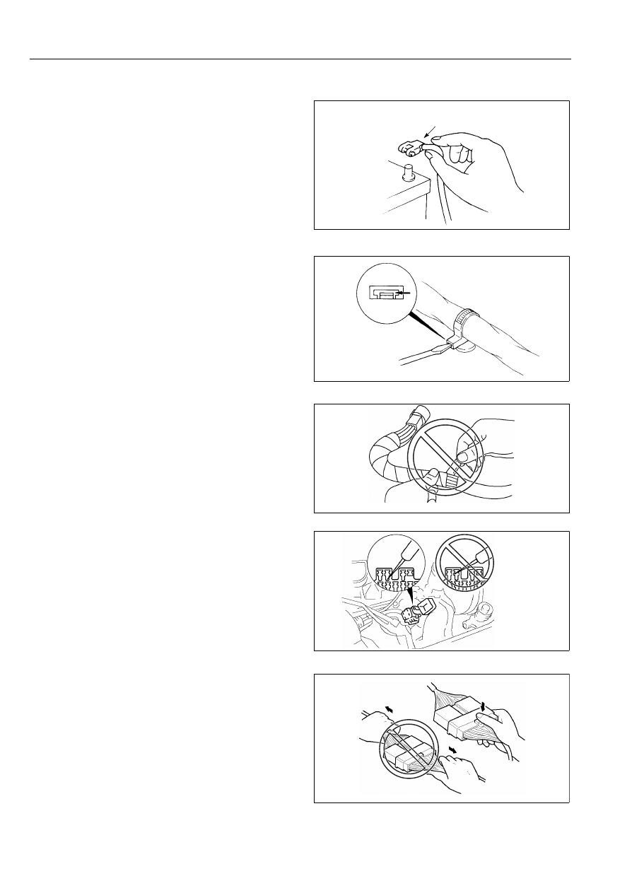
ELECTRICAL PARTS
B6U000000006W03
Battery Cable
• Before disconnecting connectors or removing
electrical parts, disconnect the negative battery cable.
Wiring Harness
• To remove the wiring harness from the clip in the
engine room, pry up the hook of the clip using a
flathead screwdriver.
Caution
• Do not remove the Harness protective tape.
Otherwise, the wires could rub against the body,
which could result in water penetration and
electrical shorting.
CONNECTORS
Data Link Connector
• Insert the probe into the terminal when connecting a
jumper wire to the data link connector.
Caution
• Inserting a jumper wire probe into the data link
connector terminal may damage the terminal.
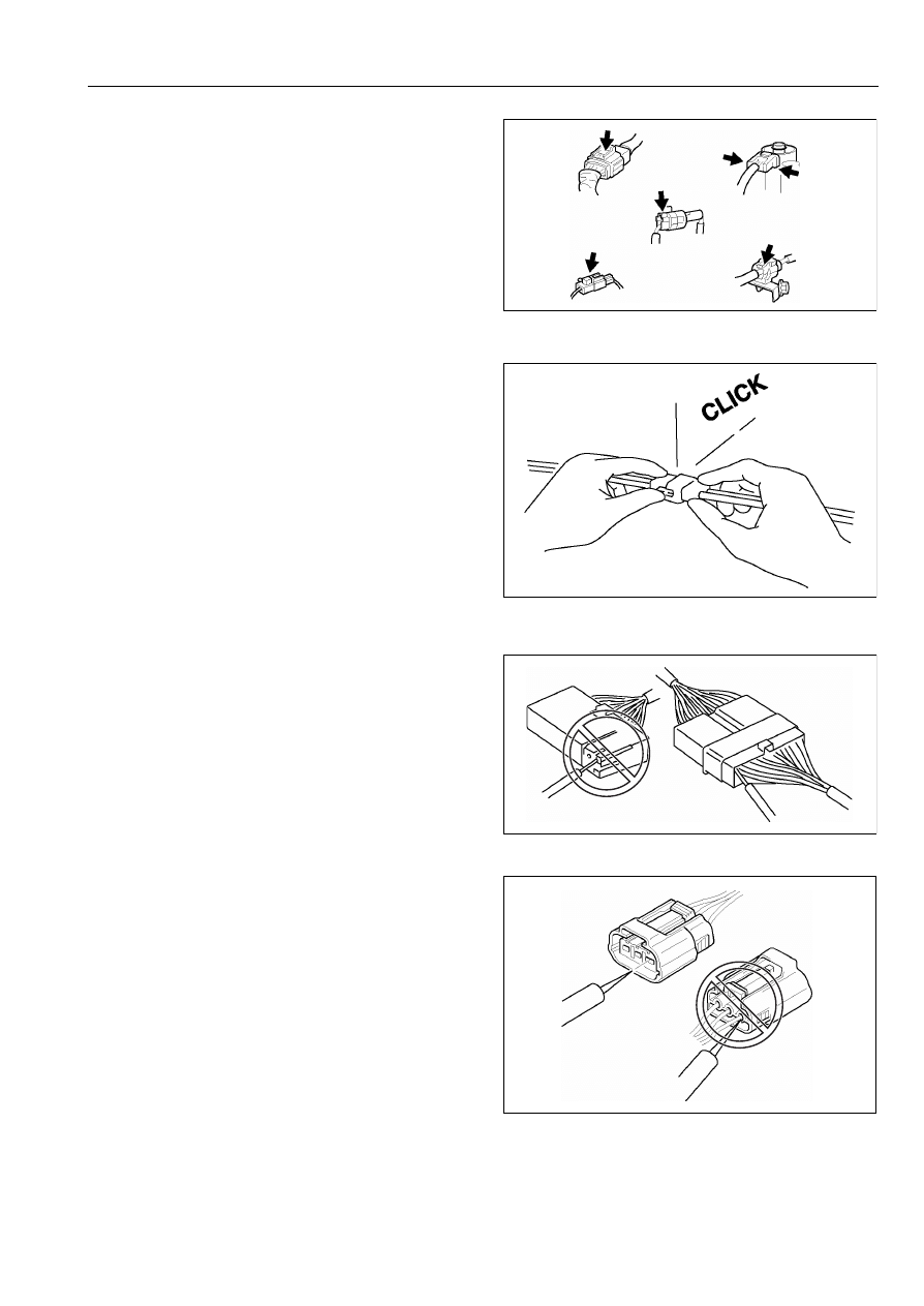
Disconnecting Connectors
• When disconnecting connector, grasp the connectors,
not the wires.
WGIWXX0007E
NEGATIVE BATTERY CABLE
WGIWXX0041E
NO GOOD
WGIWXX0039E
WGIWXX0040E
NO GOOD
X3U000WAY
NO GOOD
GOOD
15
Electrical System General Procedures
00P
• Connectors can be disconnected by pressing or
pulling the lock lever as shown.
Locking Connector
• When locking connectors, listen for a click indicating
they are securely locked.
Inspection
• When a tester is used to inspect for continuity or
measuring voltage, insert the tester probe from the
wiring harness side.
• Inspect the terminals of waterproof connectors from
the connector side since they cannot be accessed
from the wiring harness side.
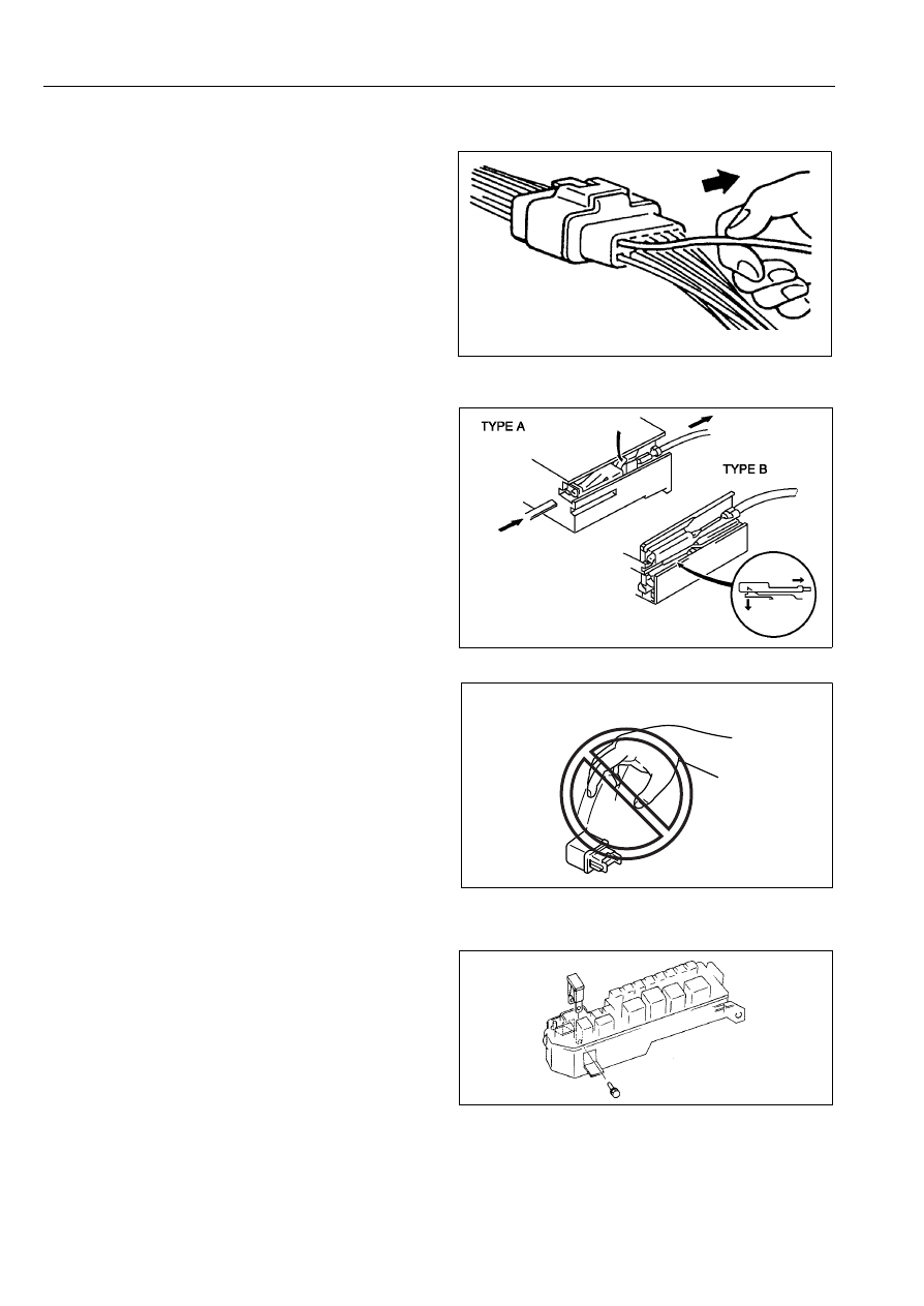
Caution
• To prevent damage to the terminal, wrap a thin
wire around the tester probe before inserting
into terminal.
X3U000WB1
WGIWXX0044E
NO GOOD
NO GOOD
NO GOOD
WGIWXX0045E
NO GOOD
WGIWXX0042E
16
Electrical System General Procedures
00P
Terminals
Inspection
• Pull lightly on individual wires to verify that they are
secured in the terminal.
Replacement
• Use the appropriate tools to remove a terminal as
shown. When installing a terminal, be sure to insert it
until it locks securely.
• Insert a thin piece of metal from the terminal side of
the connector and with the terminal locking tab
pressed down, pull the terminal out from the
connector.
Sensors, Switches, And Relays
• Handle sensors, switches, and relays carefully. Do not
drop them or strike them against other objects.
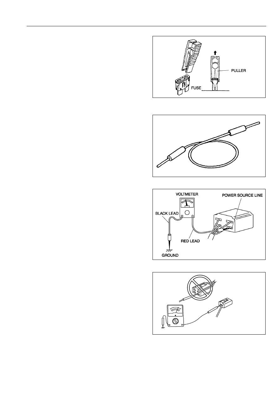
Fuse
Replacement
• When replacing a fuse, be sure to replace it with one
of the same capacity. If a fuse fails again, the circuit
probably has a short and the wiring should be
inspected.
• Be sure the negative battery terminal is disconnected
before replacing a main fuse.
X3U000WB5
X3U000WB6
NO GOOD
YMU000WA1
X3U000WB4
17
Electrical System General Procedures
00P
• When replacing a pullout fuse, use the fuse puller.
ELECTRICAL TROUBLESHOOTING TOOLS
Jumper Wire
• A jumper wire is used to create a temporary circuit.
Connect the jumper wire between the terminals of a
circuit to bypass a switch.
Caution
• Do not connect a jumper wire from the power
source line to a body ground. This may cause
burning or other damage to wiring harnesses or
electronic components.
Voltmeter
• The DC voltmeter is used to measure circuit voltage. A
voltmeter with a range of 15 V or more is used by
connecting the positive (+) probe (red lead wire) to the
point where voltage will be measured and the negative
(-) probe (black lead wire) to a body ground.
Ohmmeter
• The ohmmeter is used to measure the resistance
between two points in a circuit and to inspect for
continuity and short circuits.
Caution
• Do not connect the ohmmeter to any circuit
where voltage is applied. This will damage the
ohmmeter.
X3U000WBB
X3U000WBC
YMU000WAL
POWER SOURCE LINE
GROUND LINE
OHMMETER
NO GOOD
YMU000WAK
Wyszukiwarka
Podobne podstrony:
BSA A10 wiring diagram id 93494 Nieznany (2)
How to Use the Electrical Wiring Diagram
Overall Electrical Wiring Diagram
77 WIRING DIAGRAM SYMBOLS
Overall Electrical Wiring Diagram
NX650 T Section 20 Wiring diagram
67 SYSTEM WIRING DIAGRAMS
honda civic from 1991 to 1996 wiring diagrams 136 1
18 Wiring Diagram
BSA A10 wiring diagram id 93494 Nieznany (2)
G 2 0 DOHC ECS Wiring Diagram doc
wiring diagram symbols
21 Wiring Diagrams
wiring diagram 3 4 cyl SMART LPG
ignition wiring basic wiring diagram BRIGGS & STRATTON
Wiring Diagrams
SC 033 EN R0 CONNECTOR WIRING DIAGRAM
12 Wiring Diagram
więcej podobnych podstron