Hepworth Heating Ltd.,
Nottingham Road, Belper, Derbyshire. DE56 1JT
General/Sales enquiries:
Tel: (01773) 824141 Fax: (01773) 820569
One Contact Local Service
Customer Services:
Tel: (01773) 828100
Fax: (01773) 828070
221837B.11.00
All replacement parts
All labour charges
All call-out charges
Thank you for installing a new Glow-worm appliance in your home.
Glow-worm appliances' are manufactured to the very highest standard so we are pleased
to offer our customers' a Comprehensive First Year Guarantee.
In the center pages are to be found your Guarantee Registration Card, which we recommend you complete and
return as soon as possible.
If this card is missing you can obtain a copy or record your registration by telephoning the Heatcall Customer
Service number 01773 828100.
Our Guarantee gives you peace of mind plus valuable protection against breakdown by covering the cost of:
Guarantee Registration
Reference in these instructions to British Standards and Statutory
Regulations/Requirements apply only to the United Kingdom.
For Ireland the rules in force must be used.
The instructions consist of three parts, User, Installation and Servicing Instructions, which includes the Guarantee Registration
Card. The instructions are an integral part of the appliance and must, to comply with the current issue of the Gas Safety
(Installation and Use) Regulations, be handed to the user on completion of the installation.
T o b e l e f t w i t h t h e u s e r
4040S
❏
✔
❏
✔
❏
✔
Instructions for Use
Installation and Servicing
REGISTER YOUR GLOW-WORM APPLIANCE
FOR 1ST YEAR GUARANTEE PROTECTION
CALL 0208 247 9857
PAS010
High Efficiency Boiler
G.C. No.
G.C. No.
41 319 92
41 319 84
Energysaver
70
80
Cat I
2H
Cat II
2H3P

2
221837B
Important Information
TESTING AND CERTIFICATION
This boiler is tested and certificated for safety and performance.
It is therefore important that no alteration is made to the boiler,
without permission, in writing, from Hepworth Heating Ltd.
Any alteration not approved by Hepworth Heating Ltd., could
invalidate the certification, boiler warranty and may also infringe
the current issue of the Statutory Requirements, see Section
1.2.
CE MARK
This boiler meets the requirements of Statutory Instrument No.
3083 The boiler (Efficiency) Regulations, and therefore is
deemed to meet the requirements of Directive 92/42/EEC on
the efficiency requirements for new hot water boilers fired with
liquid or gaseous fuels.
Type test for purposes of Regulation 5 certified by: Notified body
0086.
Product/productioncertifiedby: Notified body 0086.
The CE mark on this appliance shows compliance with:
1. Directive 90/396/EEC on the approximation of the laws
of the Member States relating to appliances burning gaseous
fuels.
2. Directive 73/23/EEC on the harmonization of the Laws
of the Member States relating to the electrical equipment
designed for use within certain voltage limits.
3. Directive 89/336/EEC on the approximation of the Laws
of the Member States relating to electromagnetic compatibility.
INFORMATION FOR THE INSTALLER AND
SERVICE ENGINEER.
Under Section 6 of The Health and Safety at Work Act 1974, we
are required to provide information on substances hazardous
to health.
CERAMIC FIBRE/INSULATION PADS,
GLASSYARN.
These can cause irritation to skin, eyes and the respiratory tract.
If you have a history of skin complaint you may be susceptible
to irritation. High dust levels are usual only if the material is
broken. Normal handling should not cause discomfort, but
follow normal good hygiene and wash your hands before
eating, drinking or going to the lavatory. If you do suffer irritation
of the eyes or severe irritation to the skin seek medical attention.
THERMOSTATS
These contain very small amounts of xylene in the sealed phial
and capillary. If broken, under normal circumstances the fluid
does not cause a problem, but in case of skin contact, wash with
cold water. If swallowed drink plenty of water and seek medical
attention.
CUT OFF DEVICES
Cut off devices with copper phial/bulb only.
Bulb contains activated charcoal and very small amounts of
chloroddifludromethane in the sealed phial and capillary. If
broken under normal circumstances the fluid does not cause a
problem. If there is irritation to the eyes or skin then seek
medical attention.
FLUE SEALANT
This contains cyclohexylaminosilane.
It may cause irritation of skin of sensitive persons. Wash contact
area with soap and water, if irritation occurs, seek medical
advice.
It will cause irritation on contact with eyes. If so, wash eye with
large amounts of fresh water for at least 15 minutes. If irritation
occurs, seek medical advice.
If swallowed drink plenty of milk and seek medical advice.
Introduction
3
Lighting the Boiler
5
General Data
1
6
Water System
2
8
Boiler Location
3
11
Flue
4
12
Preparation
5
14
Water and Condensate Connections
6
16
Flue Installation
7
17
Gas Connection
8
20
Electrical Connection
9
21
Commissioning
10
22
User Information
11
23
Servicing
12
24
Fault Finding
13
26
Replacement Parts
14
33
Spare Parts
15
39
CONTENTS
DESCRIPTION SECTION
PAGE No.
INSTRUCTIONS
FOR USE
INSTALLATION
INSTRUCTIONS
SERVICING
INSTRUCTIONS
3
221837B
0163M
max
min
0
te m
p
Instructions for Use
Introduction
Please read these instructions and follow them for the safe and
economical use of your boiler.
This boiler is designed to provide central heating from a fully
pumped open vented or sealed water system with a fully indirect
cylinder.
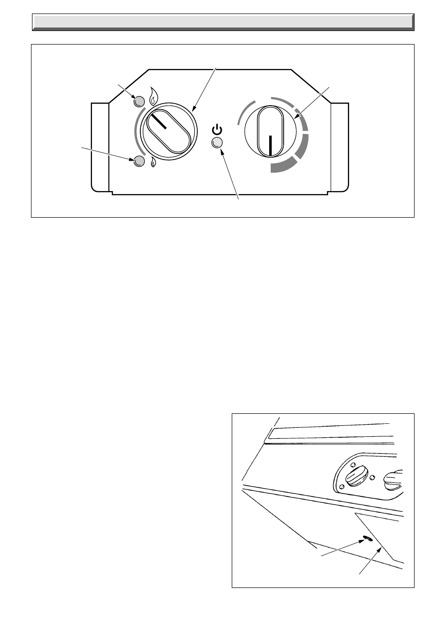
The boiler is fully automatic in operation, having two user
controls, high/low control on the left and the control thermostat
on the right, see diagram 1.
The “high/low” control can set to “Low” during the summer
months.
Important Notice
This boiler is for use on natural gas (G20) as distributed in the
United Kingdom and Ireland, but may be converted for use on
L.P.G. Propane (G31) with the use of a conversion kit, i.e.
Energysaver 80, Kit No.444758.
If your boiler has been converted to use L.P.G. Propane the
following note applys:
Propane cylinders are under pressure and should never be
stored or used indoors residentially.
They should only be kept outside.
Under no circumstances should LPG Propane cylinders be
fitted or stored in basement areas or boiler house.
Gas Safety (Installation and Use) Regulations
In your interest and that of gas safety it is the Law that ALL gas
appliances are installed by a competent person in accordance
with the current issue of the above regulations.
Gas Leak or Fault
If a gas leak or fault exists or is suspected, the BOILER MUST
BE TURNED OFF, including the electrical supply and MUST
NOT BE USED UNTIL THE FAULT HAS BEEN PUT RIGHT.
Advice/help should be obtained from your installation/servicing
company or the local gas undertaking.
Maintenance/Servicing
To ensure the continued efficient and safe operation of the
boiler it is recommended that it is checked and serviced as
necessary at regular intervals. The frequency of servicing will
depend upon the particular installation conditions and usage,
but in general once a year should be enough.
It is the Law that any servicing must be carried out by a
competent person.
To obtain service, please call your installer or Heatcall (Glow-
worm’s own service organisation) using the telephone number
given on the information plate, see diagram 2.
Please be advised that the ‘Benchmark’ logbook should be
completed by the installation engineer on completion of
commissioning and servicing.
All CORGI Registered Installers carry a CORGI ID card, and
have a registration number. Both should be recorded in your
boiler Logbook. You can check your installer is CORGI registered
by calling CORGI direct on :- 01256 372300.
GREEN
LIGHT
FOR HIGH
FLAME
GREEN
LIGHT
FOR LOW
FLAME
CONTROL
THERMOSTAT
KNOB
HIGH/LOW CONTROL KNOB
ORANGE DEMAND LIGHT
Diagram 1
Diagram 2
RESET BUTTON
INSTRUCTION LABEL
7891
4
221837B
Instructions for Use
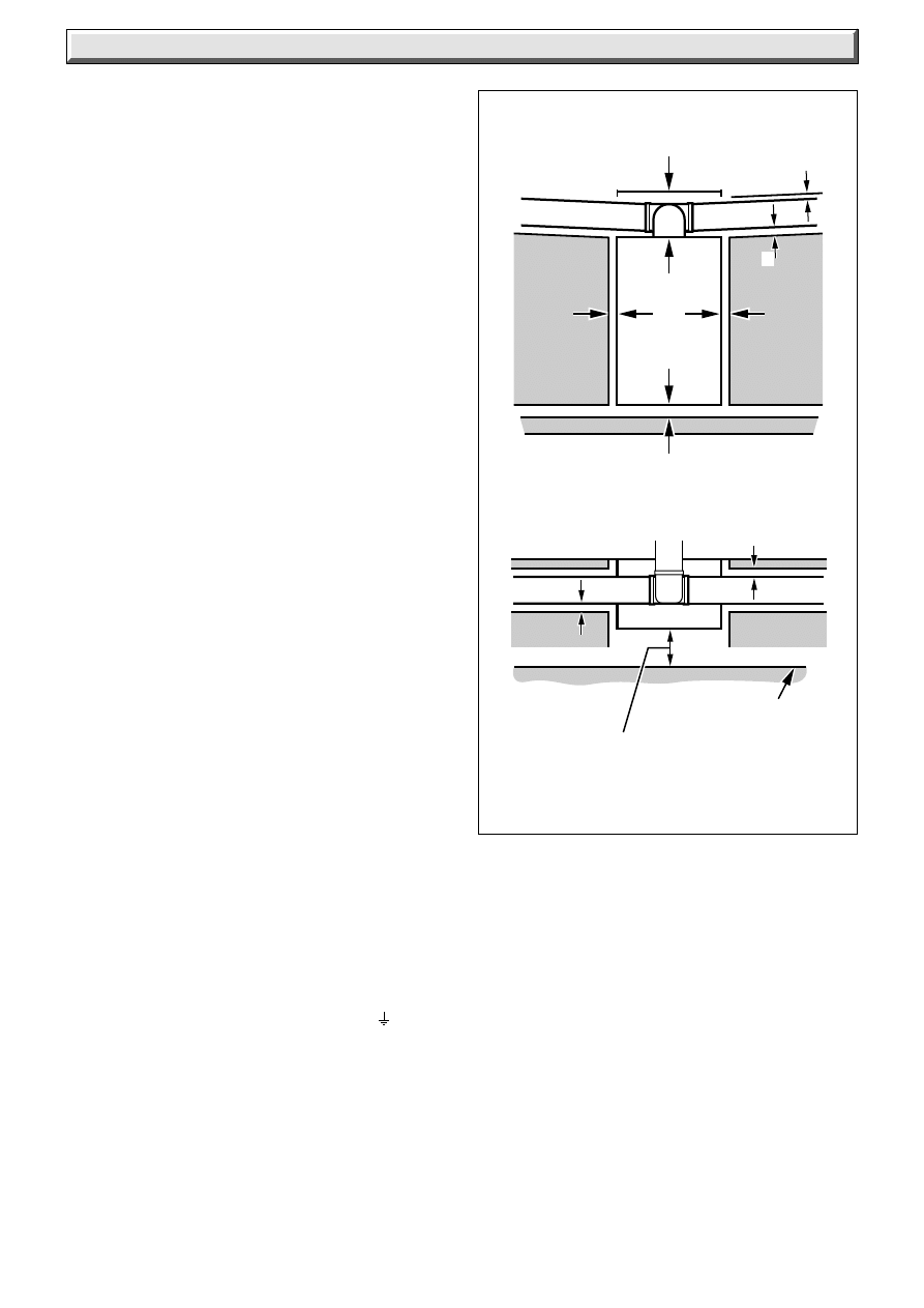
Boiler Clearances
If fixtures are positioned close to the boiler, space must be left
as shown in diagram 3. Enough space must also be left in front
of the boiler to allow for servicing.
Boilers Installed in a Compartment or
Cupboard
If the boiler is installed in a cupboard or compartment do not
obstruct any ventilation openings.
Do not use the cupboard or compartment for storage.
Regularly make sure that the air vent openings are clear of
obstructions.
Cleaning
WARNING. This appliance contains metal parts (components)
and care should be taken when handling and cleaning, with
particular regard to edges.
Clean the casing occasionally by wiping it over with a damp
soapy cloth or dry polishing duster.
Do not use an abrasive cleaner.
Protection Against Freezing
If the boiler is to be out of use for any long period of time during
severe weather conditions we recommend that the whole of the
system, including the boiler, be drained off to avoid the risk of
freezing up. Make sure that, if fitted, the immersion heater in the
cylinder is switched off.
If you have a sealed water system contact your installation/
servicing company as draining, refilling and pressurising must
be carried out by a competent person.
Boiler Electrical Supply
WARNING. The boiler must be earthed.
The boiler must only be connected to a 240V~50Hz supply,
protected by a 3A fuse.
All wiring must be in accordance with the current issue of
BS7671.
The colours of three core flexible cable are:
Brown - live, Blue - neutral, green and yellow - earth.
As the markings on your plug may not correspond with these
colours, continue as follows:
The wire coloured blue must be connected to the terminal
marked “N” or “Black”.
The wire coloured brown must be connected to the terminal
marked “R” or “Red”.
The wire coloured green and yellow must be connected to the
terminal marked “E”, “Green” or the earth symbol
.
Electrical Supply Failure
Failure of the electrical supply will cause the burner to go out.
Should this happen, operation of the boiler will normally resume
after the electrical supply is restored.
If the burner does not relight after an electrical supply failure the
overheat device may need resetting, press the reset button on
the underside of the boiler, see diagram 2.
Diagram 3
PERMANENT
SURFACE
*
5
*
5
5
5
150
100
500
*
INCREASE THIS DIMENSION TO
25mm FROM COMBUSTIBLE MATERIAL
CLEARANCE OPPOSITE TO FLUE EXIT
MUST BE ADEQUATE FOR THE
INTERNAL INSTALLATION
0157M
5
*
5

5
221837B
Overheat Safety Cutoff
If the cutoff operates on any other occasion than an electrical
failure, press the reset button as stated in “Electrical Supply
Failure”.
If the boiler fails to relight contact your installation/servicing
company.
To Turn the Boiler On
Sealed Water Systems.
CAUTION A sealed water system must be filled and pressurised
by a competent person.
Only light the boiler when you are sure that the system and
boiler have been filled and pressurised.
The pressure gauge should show at least 0.7bar, anything less
than this figure could indicate a leak and you MUST contact your
installation/servicing company.
If there is any doubt about the boiler and system being full of
water consult your installation/servicing company.
All Systems
Turn the electrical supply on to the boiler and check that any
remote controls are set to your requirements (refer to
manufacturer’s instructions for these items).
On demand, the orange light will come on.
Turn the left hand switch to “high” flame.
Turn the control thermostat knob, at the right, clockwise to any
position between “MIN” and “MAX., see diagram 1. The
maximum setting is about 82
o
C (180
o
F).
The boiler will not light between “O” and “MIN”.
The boiler lighting operation is now automatic as follows:
The fan operates, followed by an ignition spark until the burner
lights on low flame after a short period it will go to high flame and
the green light will come on.
The burner will remain alight until switched off by the control
thermostat or other remote control.
If the control thermostat is turned “Off”, by hand, wait at least 30
seconds before turning on again.
When the boiler thermostat is satisfied the burner and green
light will go out.
When the system controls are satisfied the burner, orange and
green lights will go out.
The automatic lighting sequence will operate again when heat
is required.
The “high/low” switch should be set to “high” for winter use, but
when domestic hot water only is required in the summer it can
be turned to “low”.
If no light comes on you should contact your installation/
servicing company, to check the controls, although the system
may be working.
To Turn the Boiler Off
For short periods, turn thermostat control knob anti-clockwise
until “O” is against the setting point. To relight the main burner,
turn the thermostat knob clockwise to any setting between ”MIN”
and “MAX”.
For longer periods, turn the thermostat control knob anti-
clockwise until “O” is against the setting point and switch off the
electrical supply to the boiler.
To relight follow the sequence given above.
Note: If the burner goes out for any reason, wait 30 seconds
before relighting.
Condensation Pluming
Like all condensing boilers this appliance will produce a plume
of condensation from the flue terminal in cool weather. This is
due to the high efficiency and hence low flue gas temperature
of the boiler.
Instructions for Use
6
221837B
Diagram 1.1
1 General
4356
WATER CONNECTIONS
28mm COPPER
CONDENSATE DRAIN
GAS CONNECTION
500
65
370
Ensure flue slopes 2
˚
down
towards the boiler
i.e. 35mm fall per metre
of flue length (2
˚
)
124
42
300
70
32
FLUE
TERMINAL
DETAIL
102
63
65
119
660
25
722
24
32
DRAIN
CONNECTION
CAPPED OFF
Substances Hazardous to Health, The Electricity at Work
Regulations and any applicable local regulations.
Detailed recommendations are contained in the current issue of
the following British Standards and Codes of Practice, BS4814,
BS5440 Part 1 and 2, BS5449, BS5546, BS6700, BS6798,
BS6891 and BS7074 Part 1 and 2, BS7478, BS7593, BS7671.
We also suggest that you have to hand a copy of the British Gas
publication, “Guidance Notes for the Installation of Domestic
Condensing Boilers”.
Manufacturer’s notes must not be taken as overriding statutory
obligations.
BSI Certification
The boiler is certificated to the current issue of P.A.S. 010 for
performance and safety.
It is important that no alteration is made to the boiler, without
permission, in writing, from Hepworth Heating Ltd.
Any alteration that is not approved by Hepworth Heating Ltd.,
could invalidate the warranty and could also infringe the current
issue of the Statutory Requirements.
1.3 Range Rating
The boiler is range rated and is factory preset to maximum, but
may be adjusted to suit individual system requirements, refer to
Table 2.
1.4 General Data
The data label is positioned on the inner case, visible when the
outer case is removed.
All dimensions on diagrams are given in millimetres (except as
noted).
Important Notice
This boiler is for use only on G20 gas, but the Energysaver 80
may be converted for use on G31 gas (L.P.G.) with an available
conversion kit.
Energysaver 80, Kit No. 444758
The boiler is delivered in one pack.
Wherever possible, all materials and components to be used
shall comply with the requirements of applicable British
Standards.
Where no British Standard exists, materials and equipment
should be fit for their purpose and of suitable quality and
workmanship.
This boiler must have fully pumped circuits, but is suitable for
use with open vented or sealed water systems.
This boiler is not suitable for outdoor locations.
1.1 Sheet Metal Parts
WARNING. When installing or servicing the boiler care should
be taken when handling sheet metal parts to avoid any possibility
of personal injury.
1.2 Statutory Requirements
The installation of the boiler MUST be carried out by a competent
person in accordance with the relevant requirements of the
current issue of:
Manufacturer’s instructions, supplied.
The Gas Safety (Installation and Use) Regulations, The
Building Regulations, The Building Standards (Scotland)
Regulations (applicable in Scotland), local Water Company
Bylaws, The Health and Safety at Work Act, Control of
7
221837B
1 General
RANGE RATING
NOMINAL
kW
HEAT INPUT
(GROSS)
Btu/h
NOMINAL
kW
HEAT
OUTPUT
Btu/h
NOMINAL
kW
HEAT
OUTPUT
Btu/h
CONDENSING
BURNER
mbar
SETTING (HOT)
PRESSURE
in.w.g
APPROX
m
3
h
GAS
RATE
ft
3
h
LOW
MIN
MID
MAX
TABLE 2.
Energysaver 80
BURNER INJECTOR MARKING: 80N
13.2
20.5
22.0
23.4
45,000 70,000 75,000 80,000
15.0
23.3
25.0
26.6
51,100 79,550 85,200 90,900
14.0
21.7
23.2
24.8
47,500 74,000 79,200 84,500
5.25 12.25 14.0
16.0
2.1
4.9
5.6
6.4
1.4
2.2
2.35
2.5
50.5
78.5
84.0
89.5
RANGE RATING
NOMINAL
kW
HEAT INPUT
(GROSS)
Btu/h
NOMINAL
kW
HEAT
OUTPUT
Btu/h
NOMINAL
kW
HEAT
OUTPUT
Btu/h
CONDENSING
BURNER
mbar
SETTING (HOT)
PRESSURE
in.w.g
APPROX
m
3
h
GAS
RATE
ft
3
h
LOW
MIN
MID
MAX
TABLE 2.
Energysaver 70
BURNER INJECTOR MARKING: 70N
13.2
17.6
19.1
20.5
45,000 60,000 65,000 70,000
15.0
20.0
21.7
23.3
51,100 68,200 73,860 79,550
14.0
18.6
20.1
21.7
47,500 63,400 68,700 74,000
7.1
12.4
14.6
16.8
2.8
5.0
5.9
6.7
1.4
1.85
2.0
2.2
50.5
67.3
72.8
78.5
MODEL
70 and 80
DATA TABLE 1.
TOTAL
WEIGHT
51.0 kg
(112.5 lb)
LIFT
WEIGHT
35.5kg
(78.5 lb)
WATER
CONTENT
2.0 Litre
(0.44 gall)
GAS
CONNECTION
Rc
1
/
2
in.
28mm copper,
flow at right, return at left
WATER
CONNECTION
ELECTRICITY
SUPPLY
240V ~ 50H
Z
, fused 3A.
The Seasonal Efficiency Domestic Boilers UK (SEDBUK)
is 87.9%.
The value is used in the UK Government’s Standard Assessment
Procedure (SAP) for energy rating of dwellings. The test data
from which it has been calculated have been certified by B.S.I.
1.5 Gas Supply
The gas installation must be in accordance with the current issue
of BS6891.
The supply from the governed meter must be of adequate size
to provide a steady inlet working pressure of 20mbar (8in wg) at
the boiler.
On completion, test the gas installation for soundness using the
pressure drop method and suitable leak detection fluid. Purge
in accordance with the above standard.
1.6 Electrical Supply
WARNING. This boiler must be earthed.
All system components shall be of the approved type and be
wired and connected in accordance with the requirements of the
current issue of BS7671 and any applicable local regulations.
Connection of the boiler and system controls to the mains supply
must be through a common isolator and must be fused 3A
maximum. This method of connection should be, by a double
pole isolating switch, which has a minimum contact separation
of 3mm on both poles. This should be readily accessible and
preferably adjacent to the appliance. It should supply the
appliance only and be easily identifiable as so doing.
Wiring to the boiler must be PVC insulated type to the current
issue of BS6500 Table 16.
Alternatively, an unswitched shuttered socket and 3 pin plug to
the current issue of BS1363, fused 3A, may be used, provided
it is not used in a room containing a bath or shower.
1.7 Condensate
The boiler condensate should, if possible, be discharged into the
household internal draining system, that is, sink or washing
machine drain. If this is not practicable, discharge can be
external, into the household drainage system or a purpose
designed soak away
The boiler is fitted with a safety device to prevent the boiler from
working if the condensate pipe gets blocked by either ice or
debris.
It is, therefore, recommended that any external condensate
drain pipe is insulated to prevent it freezing up.
Alternatively, a larger diameter pipe can be used and insulated.
The condensate drain pipe should be checked during any
servicing and any debris found removed.
Refer to the British Gas publication “Guidance Note for the
Installation of Domestic Condensing Boilers” for further
information.
1.8 Heating System Controls
The heating system should have installed: a programmer and
room thermostat controlling the boiler.
Thermostatic radiator valves may be installed in addition to the
room thermostat.
Note: For further information, see The Building Regulations
1991 - Conservation of fuel and power, 1995 edition - Appendix
G, table 4b.
1.9 Anti-theft Kits
Anti-theft kits are available for these appliances, contact Hepworth
Heating Ltd. for further information.
8
221837B
1.5
1.0
0.5
0
50
40
30
20
0
0
5
10 15 20 25 30
Flow rate (litres/minute)
Water pressure loss
(metres head of water)
Water pressure loss
(inches head of water)
10
60
0
1
2
3
4
5
6
Flow rate (gallons/minute)
35 40
70
7
8
2.0
0164M
Diagram 2.1
Diagram 2.2
TABLE 3
2 Water System
4364 S
BOILER
DRAIN
POINT
Design
Minimum
Flow Rate
Flow Rate
Energysaver 70 26.8L/min 19.6L/m
Energysaver 80 30.5L/min 22.5L/m
2.1 Draining Tap
The boiler is provided with a draining point at the lower left hand
side of the burner manifold, to be used for draining the boiler,
see diagram 2.1.
A draining tap must be provided at the lowest points of the
system which will allow the entire system and hot water cylinder
to be drained.
Draining taps shall be to the current issue of BS2879.
2.2 Safety Valve
A safety valve need not be fitted to an open vented system.
2.3 Pump
The pump should be fitted in the flow pipe from the boiler and
have isolating valves each side, integral if possible.
A variable duty pump should be set to give a temperature
difference of 11
o
C (20
o
F) between the flow and return, with the
thermostat set at “MAX”, which is about 82
o
C (180
o
F), to give a
design flow rate as shown in Table 3.
See chart for pressure drop of the boiler, diagram 2.2.
The use of microbore systems is not recommended.
2.4 Bypass
A BYPASS MUST BE FITTED, see diagram 2.3 for a suitable
position.
The flow rate through the boiler must not be allowed to fall below
that given in Table 3.
Where the water system can allow the boiler and pump to
operate on bypass only, the bypass must be placed at least
1.5m away from the boiler.
2.5 Inhibitor
Attention is drawn to the current issue of BS5449 and BS7593
on the use of inhibitors in central heating systems.
If an inhibitor is to be used, contact an inhibitor manufacturer for
their recommendations as to the best product to use.
Note: This boiler has a totally copper water system and does not
require a special inhibitor normally associated with other types
of high efficiency (“condensing”) boilers.
If an existing system is to be reused take special care to drain
the entire system, including the radiators, then thoroughly
cleaning out before fitting the boiler whether or not adding an
inhibitor.
2.6 Open (Vented) Water System
The boiler must be supplied from an unrestricted water supply
taken from a feed and expansion cistern situated at a maximum
height of 27metres (90ft) above the boiler.
Maximum water pressure 3 Bar.
The cold feed must be 15mm minimum size.
The vent must rise continuously and be unrestricted.
It is important that the relative positions of the pump, cold feed
and open vent are as shown in diagram 2.3.
2.7 Domestic Hot Water Cylinder
The domestic hot water cylinder must be of the double feed fully
indirect type. Not the single feed self priming type.
9
221837B
0246M
2 Water System
Diagram 2.3
Diagram 2.4
3 LITRES (0.66 gals)
MAKE-UP BOTTLE
(if required)
NON-RETURN
VALVE
AUTO
AIR
VENT
FLOW
DRAIN
COCK
BOILER
SAFETY
VALVE
(Make-up
alternatives)
EXPANSION
VESSEL
PRESSURE
GAUGE
CIRCULATING
PUMP
FILLING POINT
AIR
RELEASE
POINT
HEATING
CIRCUIT
22mm (min)
BY-PASS WITH
LOCKSHIELD
VALVE
RETURN
Open (vented) ststem.
Recommended
rellationship between
pump,cold feed and vent.
22mm (MIN.) VENT
FEED AND
EXPANSION
CISTERN
15mm (MINIMUM)
COLD FEED
22mm (MINIMUM) BY-
PASS WITH
LOCKSHIELD VALVE
1150mm
MIN.
BOILER
150mm
MAX
FLOW
PUMP
RET.
CYLINDER
FLOW
RET.
HEATING
450mm
MIN.
HEIGHT
2.8 Domestic Hot Water System - Unvented
Where a storage system will not have a vent to atmosphere the
installation must comply with the Building Regulations and local
Water Company bylaws, see also the current issue of BS5546
and BS6700.
If fitting to an existing system the local authority should be
informed.
2.9 Sealed Water Systems
The installation must comply with the appropriate requirements
of the current issue of BS4814, BS5449, BS6759, BS6798 and
BS7074 Part 1 and 2.
See diagram 2.4 for a suggested layout.
2.10 Safety Valve
A safety valve must be fitted to a sealed system.
It shall be preset, nonadjustable with a lift pressure of 3bar,
incorporating seating of a resilient material, a test device and a
connection for drain.
The drain from the safety valve must be routed clear of any
electrical fittings and positioned so that any discharge can be
seen.
5814
10
221837B
2 Water Sytem
Diagram 2.5
METHOD 1
METHOD 2
METHOD 3
SUPPLY STOP
VALVE
SUPPLY
PIPE
HOSE
UNIONS
SERVICING
VALVE
TEMPORARY
HOSE
HEATING
SYSTEM
HEATING
SYSTEM
TEMPORARY
HOSE
HOSE
UNIONS
SERVICING
VALVE
SUPPLY
PIPE
SUPPLY STOP
VALVE
DOUBLE CHECK
VALVE ASSEMBLY
HEATING
SYSTEM
SERVICING
VALVE
SUPPLY
STOP VALVE
SUPPLY
PIPE
HOSE
UNIONS
DOUBLE CHECK
VALVE ASSEMBLY
OVERFLOW
CISTERN
COMBINED
CHECK VALVE
AND VACUUM
BREAKER
PRESSURE
REDUCING
VALVE
0051M
2.11 Expansion Vessel
A diaphragm type expansion vessel, conforming to the current
issue of BS4814 (see also BS7074 Part 1 and 2) must be
connected at a point close to the inlet side of the circulating
pump, see the diagrammatic layout, diagram 2.4 unless laid
down differently by the manufacturer.
The expansion vessel volume depends on the total water
system volume and the initial system design pressure. For any
system an accurate calculation of vessel size is given in the
current issue of BS7074 Part 1.
Example: For an initial system design pressure of 0.7bar, the
minimum total vessel volume required is 0.063xTotal System
volume.
Note: A higher initial design pressure requires a larger volume
expansion vessel.
Guidance on vessel sizing is also given in the current issue of
BS5449 and BS7074 Part 1.
The charge pressure must not be less than the static head of the
system, that is, the height of the highest point of the system
above the expansion vessel.
The water content of the boiler is given in the Data Table 1.
2.12 Pressure Gauge
A pressure gauge with a set pointer and covering at least 0 to
4bar (0 to 60lb/in
2
) shall be fitted permanently to the system in
a position where it can be seen when filling the system.
2.13 Domestic Hot Water Cylinder
SINGLE FEED INDIRECT CYLINDERS ARE NOT SUITABLE.
The hot water cylinder must be of the indirect coil type. It must
be suitable for working at a gauge pressure of 0.35bar above
the safety valve setting.
2.14 Water Makeup
Provision should be made for replacing water loss from the
system using a make up bottle or filling loop mounted in a
position higher than the top point of the system, connected
through a non-return valve to the return side of either the
heating circuit or the hot water cylinder.
Alternatively, provision for make up can be made using a filling
loop.
2.15 Filling a Sealed Water System
Provision for filling the system at low level must be made. Three
methods are shown in diagram 2.5. There must be no permanent
connection to the mains water supply, even through a non-
return valve.
11
221837B
Diagram 3.1
PERMANENT
SURFACE
*
5
*
5
5
5
150
100
500
*
INCREASE THIS DIMENSION TO
25mm FROM COMBUSTIBLE MATERIAL
CLEARANCE OPPOSITE TO FLUE EXIT
MUST BE ADEQUATE FOR THE
INTERNAL INSTALLATION
0157M
5
*
5
3 Boiler Location
NOTE:
The boiler may be installed in any room although particular
attention is drawn to the requirements of the current issue of
BS7671 with respect to the installation of a boiler in a room
containing a bath or shower.
Any electrical switch or boiler control using mains electricity
should be so situated that it cannot be touched by a person
using the bath or shower. The electrical provisions of the
Building Standards (Scotland) Regulations are applicable to
such installations in Scotland.
The boiler must be mounted on a flat wall which is sufficiently
robust to take its total weight, see Data Table 1.
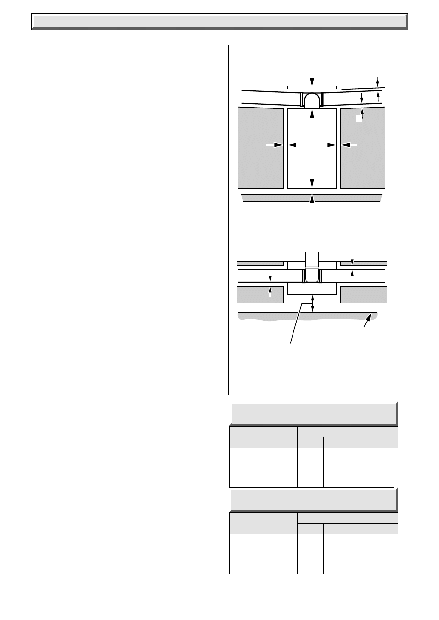
3.1 Boiler Clearances
The boiler must be positioned so that at least the minimum
operational and servicing clearances are as shown in diagram
3.1.
Additional clearances may be required around the boiler for
installation purposes, dependent upon site conditions.
3.2 Timber Frame Buildings
If the boiler is to be installed in a timber frame building it should
be fitted in accordance with the Institute of Gas Engineers
document IGE/UP/7/1998. If in doubt seek advice from the
local gas undertaking or Hepworth Heating Ltd.
3.3 Room Ventilation
The boiler is room sealed, so when installed in a room or space
a permanent air vent is not required.
3.4 Cupboard or Compartment Ventilation
Where the boiler is fitted in a cupboard or compartment,
permanent high and low level ventilation must be provided. The
ventilation areas required are given in Table 4.
Where the installation of the boiler will be in an unusual location,
special procedures are necessary, refer to the current issue of
BS6798 for guidance.
Make sure that the cupboard or compartment air vents are
positioned to be clear of obstructions at all times.
A compartment used to enclose the boiler must be designed
and constructed specifically for this purpose.
The doorway opening should be of sufficient size to allow for
easy removal of the boiler.
high level
low level
cms
in
2
cms
in
2
TABLE 4
ENERGYSAVER 70
high level
low level
cms
in
2
cms
in
2
TABLE 4
ENERGYSAVER 80
Ventilation from
240
37.2
240
37.2
room
Ventilation from
120
18.6
120
18.6
outside
Ventilation from
210
32.6
210
32.6
room
Ventilation from
105
16.3
105
16.3
outside
12
221837B
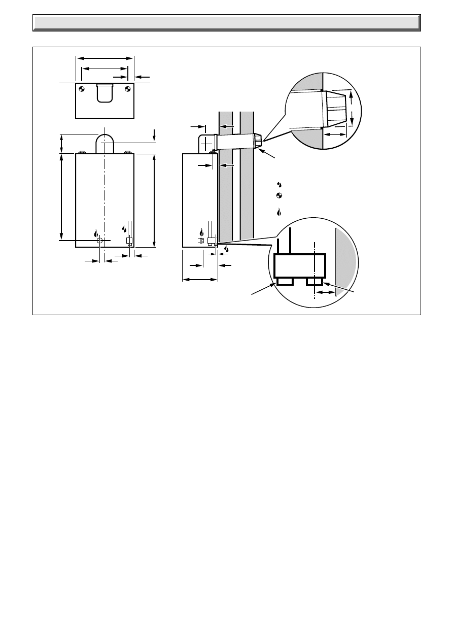
Diagram 4.1
0158M(a)
2
˚
35mm
1metre
SIDE FLUE
FRONT VIEW
Make sure flue slopes
2
˚
down
towards the boiler
that is 35mm fall per metre
of flue length (2
˚
)
Make sure flue slopes
2
˚
down towards
the boiler
that is 35mm fall
per metre
of flue
length (2
˚
)
300mm
2
˚
10.5mm
REAR FLUE
SIDE VIEW
4 Flue
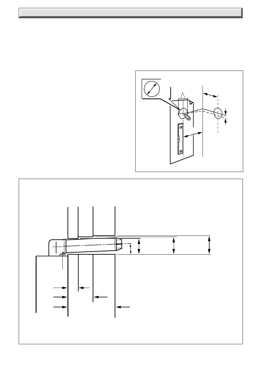
NOTE:
The flue must be installed in accordance with the current issue
of BS5440 Part 1.
Important. The flue must be installed with a fall of: 35mm per
metre (2
o
) TOWARDS the boiler, see diagram 4.1.
It is of no advantage to exceed the angle of 2
o
, indeed sealing
of the fan to the flue elbow may become more difficult as the
angle is increased.
The air and flue duct connect to the top of the boiler using an
elbow which can be positioned to the side or rear.
The rear and side flue assemblies are designed for internal
installation, but if necessary, due to insufficient clearances
(boiler/flue terminal location) they can be installed from the
outside.
For a wall thickness up to 300mm the flue can be fully installed
from the inside.
For a wall thickness over 300mm the external cut hole will need
to be made good from the outside.
The standard flue is able to provide the duct lengths as shown
in diagram 4.2 for a rear flue and diagram 4.3 for a side flue.
If a longer flue duct is required, do not extend the ductings. A
1, 2 or 3metre flue and terminal can be supplied.
See diagrams 4.2 and 4.3
S = "External wall face" to "boiler casing"
Diagram 4.3
REAR FLUE LENGTHS
SIDE FLUE LENGTHS
Diagram 4.2
R = Wall Thickness
STD Flue pack
80mm to 311mm
STD Flue pack
75mm to 442mm
3m Flue pack
75mm to 2933mm
2m Flue pack
75mm to 1953mm
3m Flue pack
80mm to 2801mm
2m Flue pack
80mm to 1821mm
1m Flue pack
75mm to 953mm
1m Flue pack
80mm to 821mm
'R'
'S'
6861
6860
13
221837B
Diagram 4.4
4 Flue
A
A
F
G
E
A
G
G
G
B,C
B,C
F
F
K
K
K
C
G
L
L
A
DIRECTLY BELOW AN OPENABLE
WINDOW, AIR VENT, OR ANY OTHER
VENTILATION OPENING
300
B
BELOW GUTTER, DRAIN/SOIL PIPE
75
C
BELOW EAVES
200
E
FROM VERTICAL DRAIN PIPES AND
SOIL PIPES
75
F
FROM INTERNAL OR EXTERNAL
CORNERS
300
G
ABOVE ADJACENT GROUND OR
BALCONY LEVEL
300
H
FROM A SURFACE FACING THE
TERMINAL
600
*
I
FACING TERMINALS
1200
K
VERTICAL FROM A TERMINAL
1500
L
HORIZONTALLY FROM A TERMINAL
300
MINIMUM SITING DIMENSIONS
FOR FANNED FLUE
TERMINALS POSITION
MINIMUM
SPACING
in mm
H,I
0103 M
4.1 Terminal Position
The minimum acceptable spacings from the terminal to
obstructions and ventilation openings are as shown in diagram
4.4.
The boiler must be installed so that the terminal is exposed to
the external air.
It is important that the position of the terminal allows the free
passage of air across it at all times.
Note: The flue will produce a plume of condensation in cold
weather, so special care must be taken in the siting of the flue
terminal so as not to cause a nuisance to adjacent property.
Where the terminal is fitted within 600mm (24in) below plastic
guttering an aluminium shield 1500mm (5ft) long should be
fitted to the underside and immediately beneath the guttering or
eaves.
Where the terminal is fitted within 450mm (18in) below eaves or
painted guttering an aluminium shield 750mm (2ft6in) long
should be fitted to the underside and immediately beneath the
guttering or eaves.
4.2 Terminal Guard
A terminal guard is required if persons could come into contact
with the terminal or the terminal could be subject to damage.
If a terminal guard is required, it must be positioned to provide
a minimum of 50mm clearance from any part of the terminal and
be central over the terminal, see diagram 4.4.
A suitable terminal guard can be obtained from:
Tower Flue Components Ltd.,
Morley Road,
Tonbridge,
Kent
TN9 1RA
their reference CGD K3 BL
4.3 Flue Collar Kit
A flue collar kit, part No. 443286 (with instructions) is available.
Please note, the use of this collar will mean that the flue lengths
will need to be altered, full instructions are given in the kit.
0161M
* It may be necessary to increase this dimension to prevent
staining of adjacent walls depending on weather conditions.
14
221837B
5 Preparation
Diagram 5.1
Diagram 5.3
BOILER
No.10 x
3
/
4
Diagram 5.2
Note: Casing securing screws
supplied in loose items pack.
Fit in order of numerical sequence.
SELF TAPPER
➁
➀
6289
6294
6295
BOILER
MOUNTING
BRACKET
INSTRUCTIONS
WALL
TEMPLATE
M5x10mm
SECURING
SCREW(4)
INNER
CASE
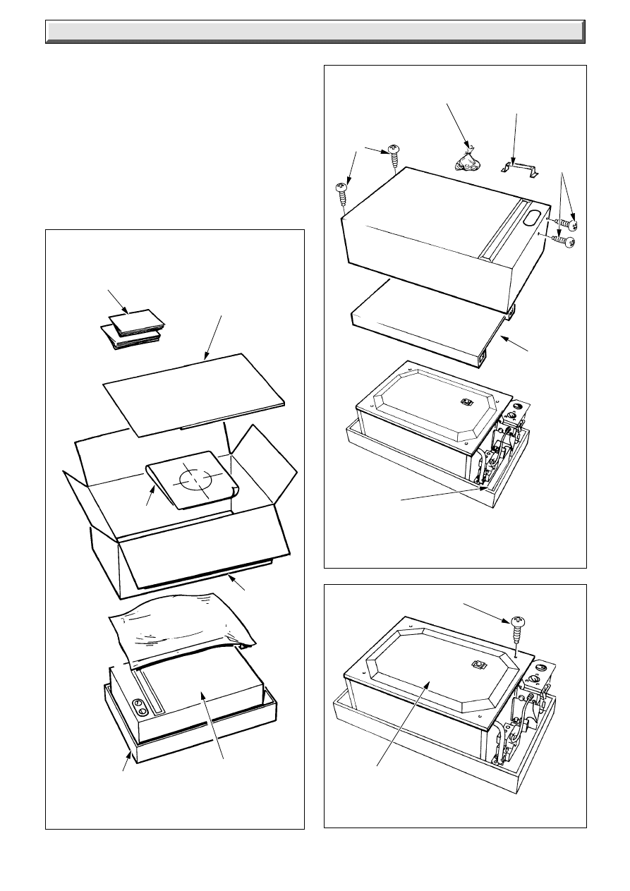
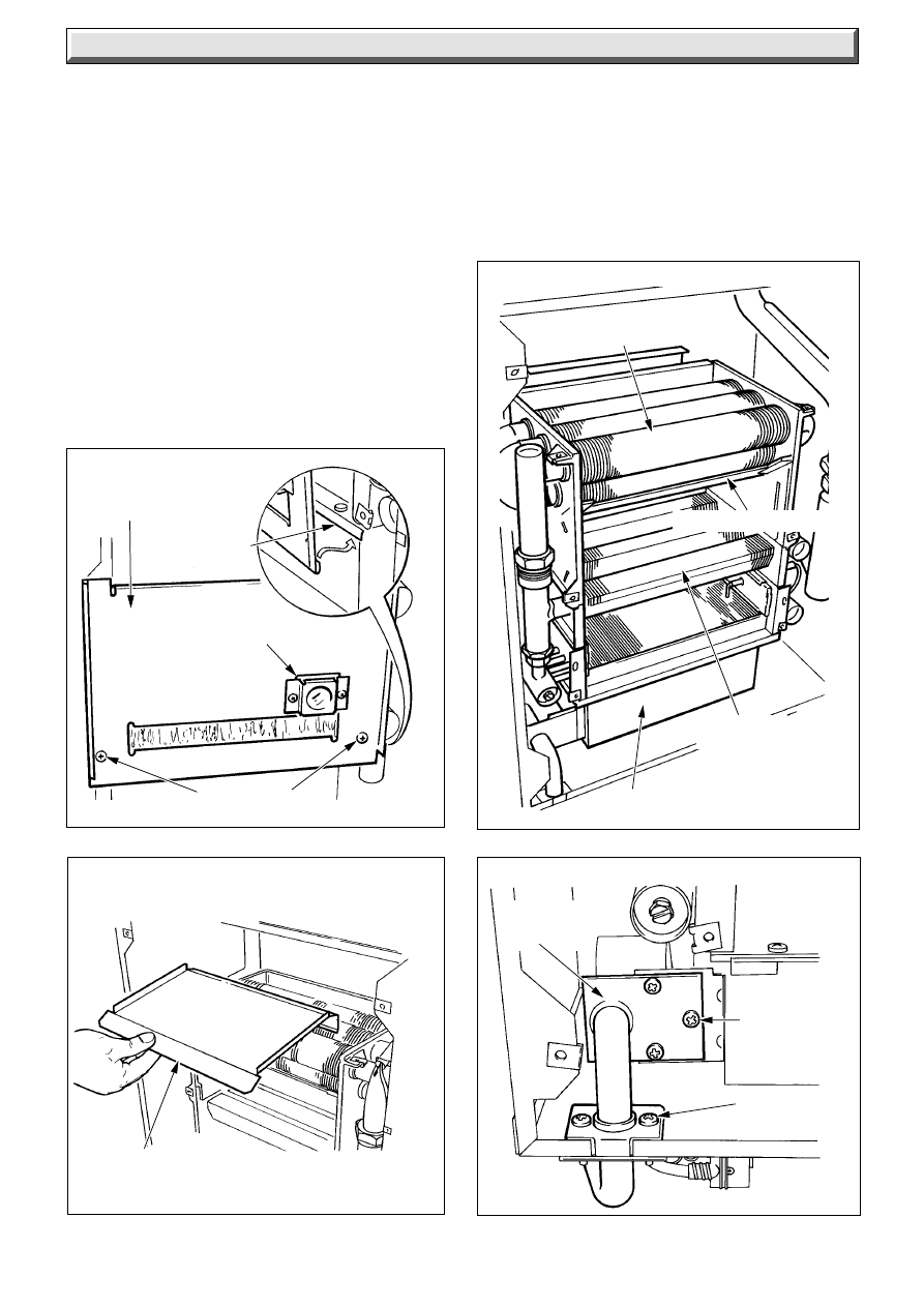
5.1 Unpacking - refer diagram 5.1
Open carton top, remove top fitting, wall template, loose items
pack and boiler mounting bracket. Remove carton wrap and
packing pieces.
Lift off white outer case front. Remove protective packing piece.
Remove the cover of the inner case, see diagram 5.3.
LOOSE ITEMS
PACK
TOP
CARTON
WRAP
TOP FITTING
PACKING
PIECE
CONTROLS
FITTING
BASE
TRAY
15
221837B
Diagram 5.4A
5 Preparation
Diagram 5.4
2˚
0248 M
0249M
See template for centre line positions
124mm
'H'=
0.035x
SIDE
FLUE
"x"
REAR FLUE
115 Minimum hole
125 up to 300mm wall
135 up to 680mm wall
56.5mm MIN
135
DIAMETER
125
DIAMETER
115
DIAMETER
2
°
WALL THICKNESS
680
300
75
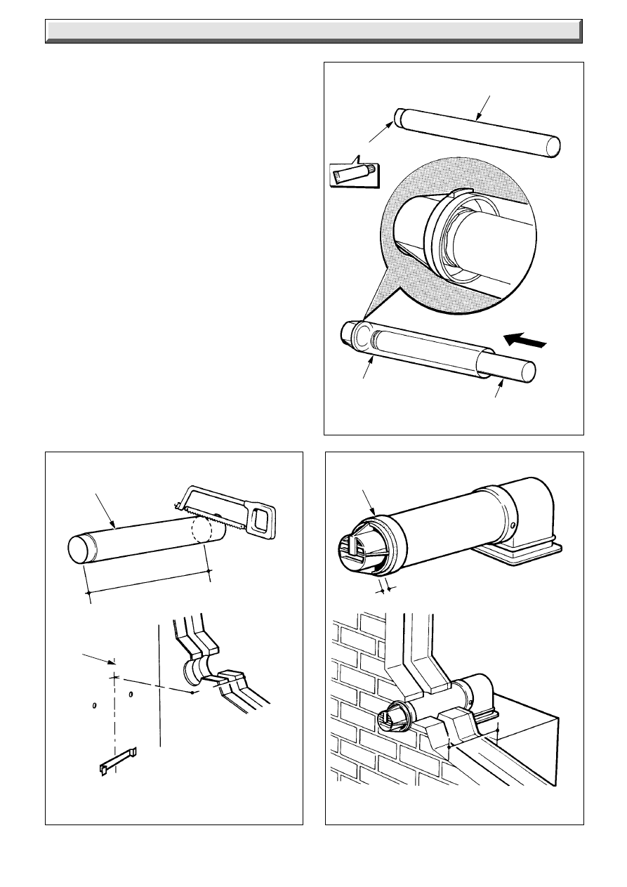
5.2 Rear and Side Flue Application
Having selected the location and flue application, with due
regard to the terminal position.
Take the template from the boiler pack and temporarily position
it on the wall, see diagram 5.4, making sure that the minimum
clearances are maintained.
For a rear flue, mark the position of the flue as diagram 5.4.
For a side flue, extend the centre line horizontally (taking into
account the required fall towards the boiler) left or right to the
corner of the adjacent surface where the flue is required to exit
to the outside.
Alternatively, the increase in the centre line height over a
distance “x” is given by H=0.035x. Mark the position of the
centre of the flue, as diagram 5.4.
5.3 Flue Hole Cutting
Having marked out the flue centre cut a hole for the flue see
diagram 5.4A for minimum core drill size for various wall
thicknesses.
This will allow for the 35mm per metre (2
o
) fall towards the boiler.
Note: If required, an optional Wall Liner Kit, part No.900862, is
available, complete with fixing instructions.
5.4 Wall Mounting Bracket
Reposition the template, making sure of dimensional alignment
with the flue centre lines.
Mark the boiler securing screws and mounting plate position,
see diagram 5.5.
Drill holes and plug, fit the securing screws, allowing sufficient
clearance to accept the keyhole fixing brackets and secure the
boiler mounting bracket to the wall.
16
221837B
6 Water Connections and Condensate
4O37 S
28mm
O.D.
COPPER
TUBING
UNION
NUT
OLIVE
FLUE GAS
SAMPLE POINT
WATER CONNECTIONS
Diagram 6.1
6.1 Water Connections
The water connections to the heating system must be as shown
in diagram 6.1.
5 Preparation
Diagram 5.6
Diagram 5.5
0170M
7Ø
3/16Ø
PLUG
MOUNTING
BRACKET
FIXING
POINT(S)
4043 S
TEMPLATE
BOILER TOP
FIXING POINTS
7Ø
3/16Ø PLUG
No.
12x2in.
No.
12x2in.
5mm
BOILER MOUNTING
BRACKET
AIR PRESSURE TUBES
CLEAR
TUBES
ELECTRICAL
CONNECTIONS
SECURING
SCREWS (3)
RED
TUBE
5.5 Boiler Preparation
Lift the boiler into position above the boiler mounting bracket,
lowering the boiler into position at the same time locating the
key hole slots of the boiler on to the securing screws, when
located secure the screws, see diagram 5.5.
6.2 Condensate Connection
The condensate drain connection is at the bottom right of the
boiler.
The drain ends in a spigot which is suitable for push-fit 22mm
(
3
/
4
in.) plastic overflow pipe, for example, Hepworth Polypipe,
Uponor, Osma, Oracstar. If using Marley, Terrain or Hunter
tubing, which is slightly larger, use the silicone sealent provided
in the fittings pack to make a leak proof joint to the drain
connection on the boiler.
The condensate discharge pipe should have a fall of 2
1
/
2
o
.
The boiler is fitted with a safety device to prevent the boiler from
working if the condensate pipe gets blocked by either ice or
debris.
It is, therefore, recommended that any external condensate
drain pipe is insulated to prevent it freezing up.
Alternatively, a larger diameter pipe can be used and insulated.
The condensate pipe should be checked during any servicing
and any debris found removed.
It is not necessary to provide air breaks, or traps in the discharge
pipe since the boiler has an integral 50mm trap and siphon.
Refer to the British Gas publication “Guidance Notes for the
Installation of Domestic Condensing Boilers” for advice on the
disposal of the boiler condensate.
17
221837B
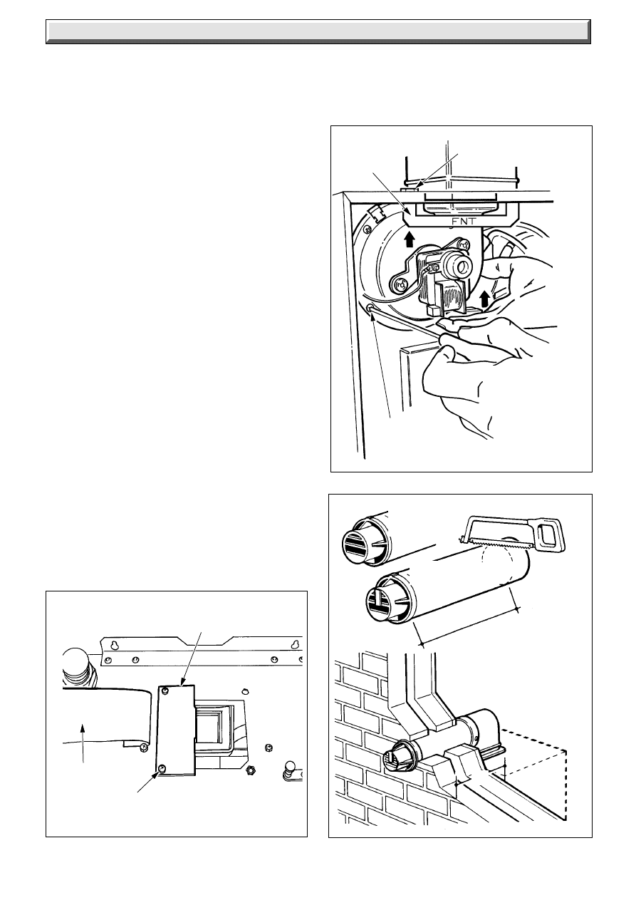
7 Flue Installation
7.1 Rear Flue
Mark and cut the air duct terminal assembly, see diagram 7.3
and the flue duct, diagram 7.4 to the lengths required, cutting
square and removing any burrs.
Refer to diagram 7.5, mark through the holes in the flue elbow
assembly and drill the duct as shown, making sure of the correct
alignment of the “Top”.
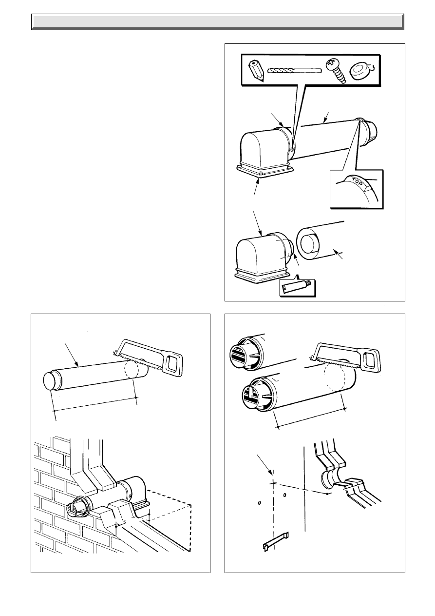
7.2 Side Flue
Mark and cut the air duct terminal assembly, see diagram 7.6
and flue duct, diagram 7.7 to the lengths required, cutting
square and removing any burrs.
Refer to diagram 7.5 mark through the holes in the flue elbow
assembly and drill the flue duct as shown, making sure of the
correct alignment of the “Top”.
7.3 Internal Flue Assembly
If access to the outside wall is not practical, the flue system can
be installed from inside. Use of the optional wall liner kit
recommended.
Apply sealant to the flue duct, locate into the air duct terminal,
see diagram 7.8.
Apply sealant to the flue elbow spigot and then locate the flue
and air duct terminal assembly to the flue elbow as shown in
diagram 7.5, making sure of the alignment of the “Top”.
Secure the air duct/terminal assembly to the flue elbow and flue
duct assembly with the two self tapping screws supplied in the
loose items pack and then seal with the tape provided.
Place the flue assembly into the flue hole.
Make sure that the flue terminal is correctly positioned and
projecting the correct distance from the outside wall face, see
diagram 7.11.
Diagram 7.1
4368 S
TRANSIT BRACKET
LABEL
SECURING
SCREWS
(2)
Diagram 7.3
4045 S
STANDARD
FLUE TERMINAL
LONG FLUE
TERMINAL
"Q" plus 67mm
"Q"
Diagram 7.2
FAN
BRACKET
4444
FAN BRACKET
SECURING SCREW (2)
FAN SECURING
SCREW (3)
18
221837B
Diagram 7.4
Diagram 7.5
Diagram 7.6
6863
6864
4079 S
FLUE DUCT
"Q" plus 82mm
BOILER
CENTRE
LINE
"N" minus 57mm
LONG FLUE
TERMINAL
STANDARD
FLUE TERMINAL
"N"
"Q"
2.8mm
DRILL SIZE
SEAL WITH
TAPE
SUPPLIED
AIR DUCT/TERMINAL
AND FLUE DUCT
ASSEMBLY
FLUE ELBOW
ASSEMBLY
SEALANT
AIR DUCT/
TERMINAL
AND
FLUE DUCT
ASSEMBLY
7 Flue Installation
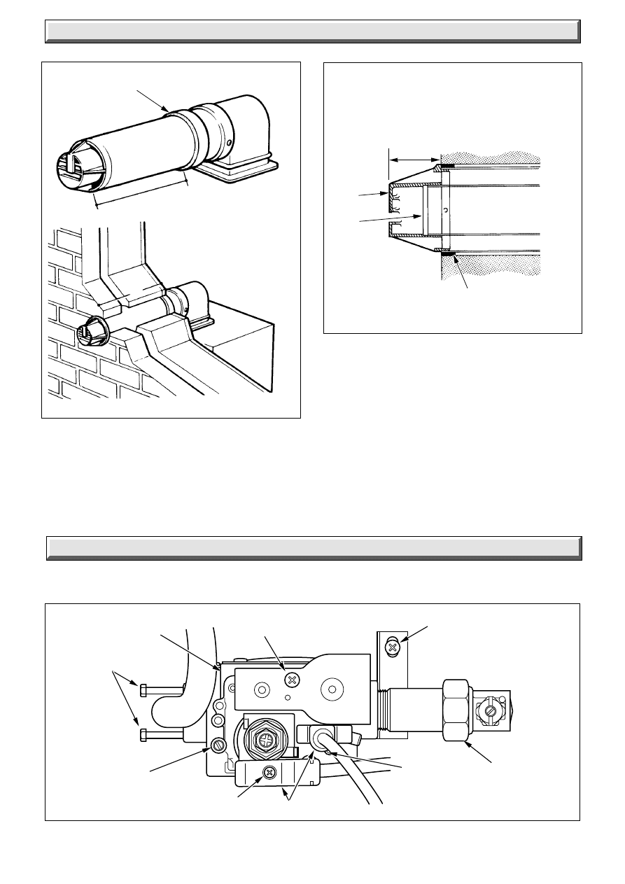
7.4 External Flue Installation
Locate the air duct/terminal assembly into the flue elbow
assembly as shown in diagram 7.5, making sure of correct
terminal alignment of the “TOP”.
Mark the position of the air duct terminal assembly securing
holes and drill two 2.8mm diameter holes through the air duct/
terminal assembly.
Apply sealant to the flue duct and locate into air duct terminal,
see diagram 7.8.
From outside, place the air duct/terminal assembly and flue
duct into the flue hole.
Make sure that the flue terminal is correctly positioned and
projecting the correct distance from the outside wall face, see
diagram 7.11.
Apply sealant to the flue elbow spigot and then locate the flue
and air duct terminal assembly as shown in diagram 7.5, make
sure of the correct alignment of the “Top”.
Secure the air duct terminal to the flue elbow with the two self
tapping screws supplied in the loose items pack, then seal with
the tape provided.
19
221837B
Diagram 7.7
"N"
7 Flue Installation
6865
BOILER
CENTRE
LINE
"N" minus 42mm
FLUE DUCT
Diagram 7.8
Diagram 7.9
6866
4080 S
FLUE
DUCT
SEALANT
AIR DUCT/
TERMINAL
ASSEMBLY
FLUE DUCT
FOAM SEAL
10mm
"Q"
7.5 Flue Elbow
Remove transit bracket and label, see diagram 7.1.
Fit the flue elbow gasket, from the fittings pack, to the casing
top.
The two fan bracket securing screws should be loosened, but
not removed, before slackening the three fan securing screws.
After locating the flue elbow into the outlet of the fan, secure the
flue elbow onto the top panel with the four M4x14 screws
provided.
Then push fan upwards, making sure that the flue elbow spigot
engages inside the fan outlet and compresses the gasket.
Complete assembly by fully tightening the two fan bracket
securing screws.
Finally tighten the three fan securing screws.
Fit the inner case door.
7.6 Wall Liner
If a wall liner is used :
For wall thicknesses up to 300mm fit the self adhesive seal to
the air duct, see diagram 7.9, make sure the joint is on top.
For wall thicknesses over 300mm see diagram 7.10.
20
221837B
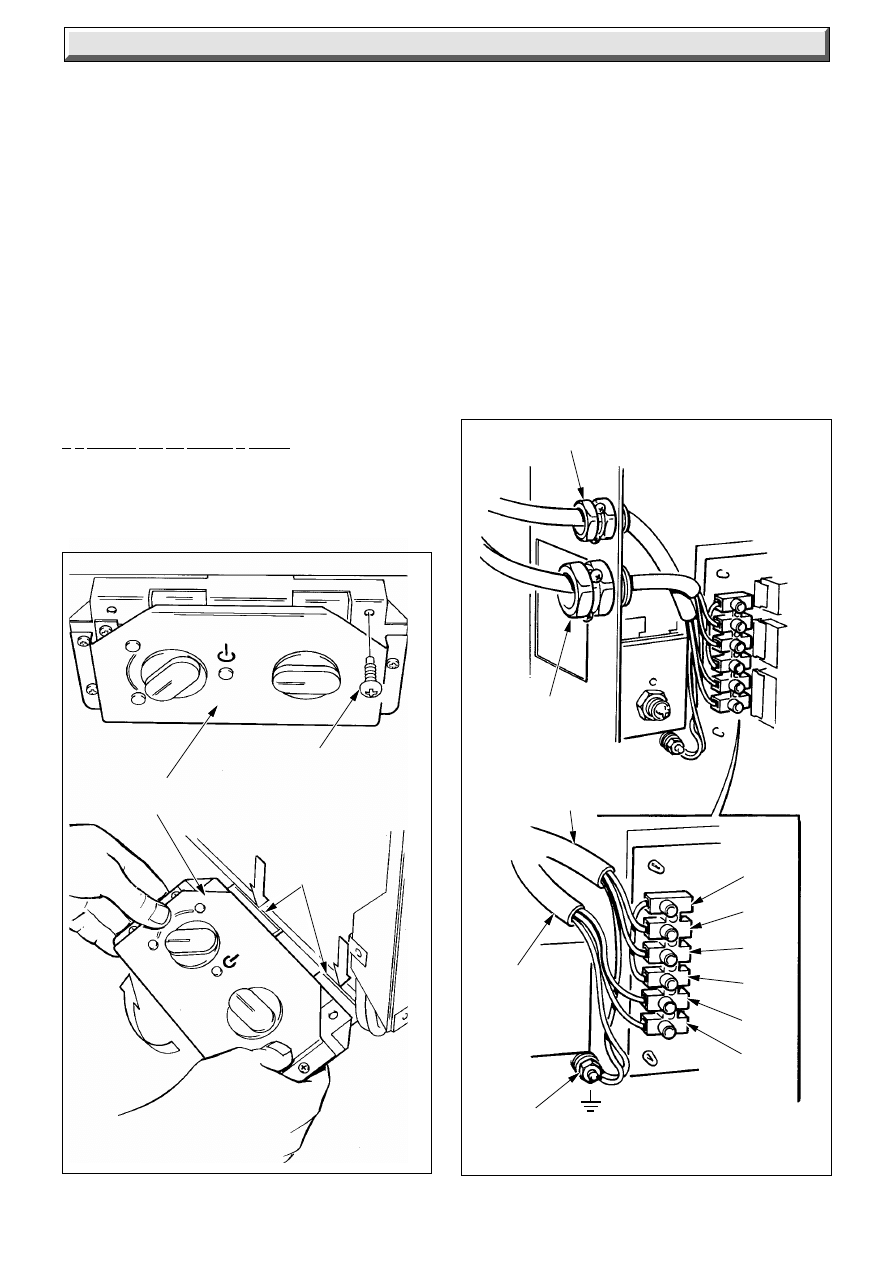
8 Gas Connection
Make the gas connection to the gas service cock, see diagram 8.1.
Diagram 7.10
Diagram 7.11
7 Flue Installation
6868
6867
FLUE
DUCT
FLUE
TERMINAL
✽
STD FLUE TERMINAL = 63
✽
STD FLUE TERMINAL = 61
✽
"Q"
"Q" minus 25mm
FOAM SEAL
SEAL
(joint to be at top)
Diagram 8.1
PLUGS
BURNER
PRESSURE
TEST POINT
SECURING
SCREW
GAS SERVICE
COCK
(SHOWN OFF)
SECURING
SCREWS
(4)
SOLENOID
SECURING SCREW
SUPPORT BRACKET
SECURING SCREW
9022
UNION
CONNECTOR
MULTI-FUNCTIONAL
CONTROL
SECURING
SCREW
21
221837B
9 Electrical Connection
Diagram 9.1
4370 S
CONTROL
BOX
SECURING
SCREW (2)
LOCATING
SLOTS
PUSH
DOWN
PULL
SLIGHTLY
FORWARDS
AND UP
NOTE:
WARNING: This boiler must be earthed.
Remove the screws as diagram 9.1.
Pull the control box forward to release from the rear slot, allow
to pivot and place into position as shown in diagram 9.1.
Using PVC insulated cable to the current issue of BS6500 Table
16, and of a suitable length, thread the cable through the small
cable clamp and connect to the appropriate terminals, see
diagram 9.2.
Standard colours are,
brown - live (L),
blue -neutral(N),
green/yellow - earth (E) .
The mains cable outer insulation must not be cut back external
to the cable clamp.
When making connections, make sure that the earth conductor
is made of a greater length than the current carrying conductors,
so that if the cable is strained the earth conductor would be the
last to become disconnected.
It is essential that the polarity is correct.
9.1 Pump and External Controls Connection
The pump must be connected directly to the control box, as
shown in diagram 9.2.
Any external controls must only be connected to terminals 1 and
SL. after removing red link.
Thread the cable(s) through the large cable clamp in the side of
the control box.
9.2 Testing - Electrical
Checks to ensure electrical safety should be carried out by a
competent person.
In the event of an electrical fault after installation of the system,
preliminary electrical system checks as below should be carried
out:
1.
Test insulation resistance to earth of mains cable.
2.
Test the earth continuity and short circuit of all
cables.
3.
Test the polarity of the mains.
The installer is requested to advise and give guidance to the
user of the controls scheme used with the boiler.
✽
Diagram 9.2
✽
RED LINK SL TO 1
REMOTE CONTROLS
4052 S
MAINS SUPPLY CABLE
GROMMET
PUMP AND
REMOTE
CONTROLS
GROMMET
PUMP CABLE
MAINS
SUPPLY
CABLE
SL
PL
PN
1
L
N
CHASSIS
EARTH
POST
22
221837B
max
min
0
te m
p
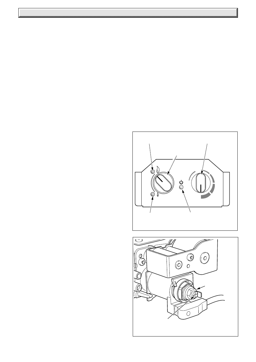
10 Commissioning
Diagram 10.1
0163 M
GREEN LIGHT FOR
HIGH FLAME
HIGH/LOW
CONTROL KNOB
CONTROL
THERMOSTAT KNOB
GREEN LIGHT
FOR LOW FLAME
ORANGE
DEMAND LIGHT
Please ensure the “Benchmark” logbook is completed and left
with the user.
10.1 Preliminaries - All Systems
Commissioning should be carried out by a competent person in
accordance with current issue of BS6798.
Make sure that the system has been thoroughly flushed out with
cold water without the pump in place.
Refit the pump, fill the system with water, making sure that all
the air is properly vented from the system and pump.
Before operating the boiler check that all external controls are
calling for heat.
10.2 Sealed Systems
Fill the system until the pressure gauge registers 2.7bar (40lbf/
in
2
). Clear any air locks and check for leakage.
Check the operation of the safety valve, preferably by allowing
the water pressure to rise until the valve lifts. This should be
within +/-0.3bar (+/-4.3lbf/in
2
), of the preset pressure. Where
this is not possible a manual check should be carried out.
Release the cold water to initial design pressure.
10.3 Initial Lighting, Testing and Adjustment
WARNING: The multifunctional control, fan and control box
operate on MAINS voltage, terminals will become live.
Check that the mains electrical supply to the boiler is switched
off and that the control thermostat is turned to “O”, see diagram
10.1.
For future reference stick the self adhesive arrow indicator, from
the loose items pack, to the data label against the rating that the
boiler is going to be set to.
Turn on the supply at the gas service cock.
Loosen the burner pressure test point screw and fit a suitable
pressure gauge, see diagram 8.1.
Turn the electrical supply on to the boiler and check that all
remote controls are calling for heat.
The orange demand light will come on, see diagram 10.1.
Turn the left hand switch to “High” flame.
Turn the control thermostat knob, at the right, clockwise to any
position between “MIN” and “MAX”, see diagram 10.1. The
maximum setting is about 82
o
C (180
o
F).
The boiler will not light between “O” and “MIN”.
The boiler lighting operation is now automatic.
The fan operates, followed by an ignition spark until the burner
lights on “Low” flame after a short period it will go to “High” flame
the green light is on.
The burner will remain alight until switched off by the control
thermostat or other remote control.
The automatic lighting sequence will operate again when heat
is required.
10.4 Testing - Gas
With the boiler on carry on as follows:
Test for gas soundness around the boiler gas components
using a suitable leak detection fluid, in accordance with the
current issue of BS6891.
Check the burner pressure at least 10 minutes after the burner
has lit, refer to Data label.
If the main burner pressure requires adjustment, see diagram
10.2.
The brass nut, controls the main (high) burner pressure.
The centre, plastic posidrive screw controls the “Low” burner
pressure.
The centre, plastic posidrive screw must be held in position
whilst adjusting the main (high) burner pressure, brass nut.
After adjustment the low pressure must be checked, by turning
the “high/low” to “low” setting.
Should any doubt exist about the gas rate, check it using the gas
meter test dial and a stop watch, at least 10 minutes after the
burner has lit, make sure that all other gas burning appliances
are off.
The rates are as shown in Table 2.
Turn the control thermostat knob to “Off”.
Remove the pressure gauge from the test point and refit the
screw, making sure that a gas tight seal is made.
When the control thermostat is turned to “Off”, by hand, wait at
least 30 seconds before turning “On” again.
There may be an initial smell given off from the boiler when new,
this is quite normal and it will disappear after a short period of
time.
Refit the electrical controls box.
Diagram 10.2
HIGH SETTING
ADJUSTMENT
(BRASS NUT)
LOWER SETTING
ADJUSTMENT (INNER
SCREW)
9023

23
221837B
10 Commissioning
10.5 Heating System
Check that all remote controls are calling for heat.
Allow the system to reach maximum temperature and examine
for water leaks.
The boiler should then be turned off and the system drained off
as rapidly as possible whilst still hot.
Refill the system, vent and again check for water soundness.
For sealed water systems adjust to initial design pressure. The
set pointer on the pressure gauge should be set to coincide with
the indicating pointer.
The overrun thermostat will keep the pump running when the
boiler shuts down, so long as the temperature within the boiler
is above a predetermined level.
When commissioning the system the boiler should be fired with
the bypass fully closed on full service, that is, central heating
and domestic hot water.
The system should then be balanced, adjusting the pump and
lockshield valves as necessary to achieve flow rates, refer to
Section 2.4.
Having achieved a satisfactory condition, operate the boiler
with the bypass closed on minimum load, normally central
heating only with one radiator operating in the main living area.
The valve should be opened gradually to achieve the appropriate
flow rate as quoted in Section 2.4. If necessary readjust the
pump.
Under NO circumstances should this valve be left in the FULLY
Closed position.
10.6 Condensate Check
After 30 minutes of running, turn the boiler off and remove the
inner case.
Check that there are no condensate leaks from the fan outlet/
flue elbow or fan inlet/flue hood joints. Also check for leaks from
the condensate drainage system.
10.7 Operational Checks
Adjust the control thermostat and any system controls to their
required settings and set “high/low” switch to “high”.
Do not attempt to adjust the thermostat calibration screw.
Operate the boiler again on full service and check that the
balancing is satisfactory, making further adjustments as
necessary to the system, radiator valves and bypass.
There must be no pumping over of water or entry of air at the
vent above the feed and expansion cistern.
If thermostatic radiator valves are fitted care must be taken to
make sure that there is an adequate flow rate through the boiler
and bypass when the valves are closed. For guidance on the
use of thermostatic radiator valves refer to the current issue of
BS7478 and British Gas Publication “Guidance Notes for
Installation of Domestic Condensing Boilers”.
To check the operation of the flame supervision device, with the
burner alight, turn gas service cock to “Off” the burner will go
out. There will be one attempt to relight, indicated by a 5 second
ignition phase.
Wait 30 seconds.
Turn the gas cock to “ON” and the burner should NOT relight.
Turn the control thermostat knob to “OFF” and then “ON” again
and the burner WILL now relight.
Turn “high/low” switch to “low” and observe low flame, then
return switch to “high”.
Refit the outer case, see diagram 5.2 and secure the case with
the screws from the fittings pack.
11 User Information
NOTES:
Instruct and demonstrate the efficient and safe operation of the
boiler, heating system and if fitted the domestic hot water
system.
Advise the user that, like all condensing boilers this appliance
will produce a plume of condensation from the flue terminal in
cool weather. This is due to the high efficiency and hence low
flue gas temperature of the boiler.
Show the user the position of “Lighting Instructions” - refer to
Instructions for Use.
Advise the user that for summer use the “high/low” switch can
be turned to “low”.
Advise the user of the precautions necessary to prevent damage
to the system and building in the event of the heating system
being out of use during frost and freezing conditions.
Advise the user, that to ensure the continued efficient and safe
operation of the boiler it is recommended that it is checked and
serviced at regular intervals. The frequency of servicing will
depend upon the particular installation conditions and usage,
but in general once a year should be enough.
Draw attention, if applicable, to the current issue of the Gas
Safety (Installation and Use) Regulations, Section 35, which
imposes a duty of care on all persons who let out any property
containing a gas appliance.
It is the Law that servicing is a carried out by a competent
person.
Reminder - Leave these instructions and the “Benchmark”
logbook with the user.
24
221837B
Diagram 12.3
4055 S
4043 S
AIR PRESSURE
TUBES
CLEAR
TUBES
RED
TUBE
SECURING
SCREWS (3)
ELECTRICAL
CONNECTIONS
FLUE HOOD
FLUE HOOD
SECURING SCREW (2)
Diagram 12.1
SECURING SCREW(2)
AIR BAFFLE
SECURING
SCREW(2)
BYPASS
HEAT
SHIELD
SECURING SCREW (2)
4372 S
12 Servicing
NOTES:
To ensure the continued efficient and safe operation of the
boiler it is recommended that it is checked and serviced at
regular intervals. The frequency of servicing will depend upon
the particular installation and usage, but in general once a year
should be enough.
It is the Law that any servicing is carried out by a competent
person.
Note. To get a products of combustion reading use the
connection on top of the boiler, see diagram 6.1.
Should the gas pressure need adjusting refer to Section 10.4.
Isolate the boiler from the electrical supply.
Before starting a service, remove the casing, refer to diagram
5.1.
Turn the gas supply off at the gas service cock, see diagram 8.1.
Unless stated otherwise, parts removed for servicing should be
replaced in the reverse order to removal.
After completing any servicing of gas carrying components,
ALWAYS test for gas soundness and carry out functional check
of controls.
Also check for condensate leaks at fan outlet/flue elbow and fan
inlet/flue hood joints.
It should be noted that the burner is water cooled and a system
drain down is necessary if the burner is removed.
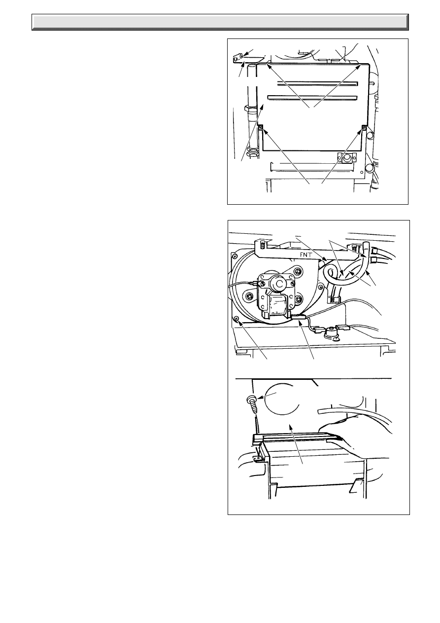
12.1 Heat Exchanger Cleaning
Remove the inner case cover, see diagram 5.3.
Remove the bypass heat shield and air baffle, see diagram
12.1.
Note. The flue hood top will “spring” up.
Disconnect the fan air pressure tubes, combustion sampling
tube, electrical connections and remove the three fan securing
screws, fan securing bracket, then fan and the flue hood.
Note. On reassembly it is suggested that the two top securing
screws for the bypass heat shield and the flue hood be partially
engaged before fitting of the bypass heat shield, see diagram
12.3.
Carefully remove the combustion chamber front panel, see
diagram 12.4.
Remove the loose baffle from the condensing section, see
diagram 12.5.
Place a container under condense drain trap, see diagram
12.8, and remove red cap.
Flush loose debris from secondary heat exchanger with
water poured from above, and allow the water to drain
through the flexible condensate tube at the right hand side
of heat exchanger into the container.
Check that this tube is not partially blocked and the water
runs freely.
If there is any build up of debris in the condensate trap, the
trap should be removed and flushed out.
Important: With use a white oxide coating will form on the
aluminium parts - this should only be removed if the coating is
blocking the gaps between the fins.
When cleaning take care that the water does not overflow the
condensate catchment tray.
Place a sheet of paper over the burner, see diagram 12.6.
Clean the primary heat exchanger, with a suitable soft brush,
see diagram 12.6.
Brush from back to front NOT left to right.
Do not use a brush with metallic bristles.
Remove the paper and any debris.
12.2 Burner
Clean the fins of the burner with a suitable soft brush, any debris
can be allowed to fall into the mixing chamber.
Do not use a brush with metallic bristles.
Note: The burner is water cooled and a system drain down is
required if removing.
25
221837B
Diagram 12.4
Diagram 12.6
Diagram 12.5
12 Servicing
4371 S
4373 S
4376S
PRIMARY
HEAT
EXCHANGER
COMBUSTION
CHAMBER FRONT
PANEL
LOCATION
SLOT
VIEWING
WINDOW
SECURING
SCREW (2)
BAFFLE
SECONDARY HEAT
EXCHANGER
CONDENSATE TRAY
BURNER
12.3 Injector
Remove the injector by releasing the three screws at the injector
manifold burner box, the two screws at the inner case base
sealing plate, see diagram 12.7, and the four screws at the
multifunctional valve, see diagram 8.1.
Make sure that the “O” ring is in place in the flanged connection
when refitting.
Clean the holes by blowing through.
Do not use a wire or sharp instrument on the holes.
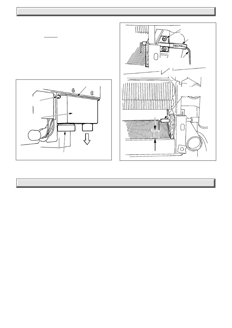
12.4 Spark Electrode
Remove the silicone sleeving and disconnect the ignition lead,
see diagram 12.9.
Remove the two securing screws.
Withdraw the electrode taking care not to damage the insulation
material. Inspect and clean taking care not to damage the
ceramic body.
When replacing make sure that the spark gap is as shown.
Diagram 12.7
4374 S
SECURING
SCREW (3)
SECURING
SCREW (2)
INJECTOR
MANIFOLD
26
221837B
13.3 Condensate Sensor
Refer to fault finding chart.
The boiler is fitted with a safety device to prevent the boiler from
working if the condensate drain pipe gets blocked.
Remove the condensate drain cap, diagram 14.2.
If condensate is backing up to the sensor position, the drain is
blocked and it must be cleared before the boiler will work.
Inspect external condensate drain pipe and clear away any
debris or ice. Release ice blockage by using warm cloths on the
pipe.
12 Servicing
Diagram 12.9
Diagram 12.8
4375 S
4060 S
GASKET
SECURING
SCREW (3)
CAP
WASTE
OUTLET
SECURING
SCREW (2)
SILICONE
SLEEVING
IGNITION AND
SENSING LEAD
SPARK
ELECTRODE
SPARK GAP
3mm to 4mm
12.5 Condensate Drain
Remove the cap at the base of the condensate drain trap, see
diagram 12.8 and carefully flush through, from the condensate
collecting tray, diagram 12.6, taking care not to allow any water
to overflow the tray.
When refitting the cap make sure a water tight seal is made.
12.6 Operational Checks
After completing a service, before fitting the casing, check the
inner case seal to ensure that it is in good condition, renew if
necessary.
13.1 Electrical
Important. On completion of the Service/Fault Finding task
which has required the breaking and remaking of the electrical
connections the earth continuity, polarity, short circuit and
resistance to earth checks must be repeated using a suitable
multimeter.
Refer to Fault Finding, Wiring diagram 13.2 and Functional
Flow diagram 13.3.
Note. Failure of an indicator light does not warrant the
replacement of an otherwise satisfactory part.
13.2 Electrical Supply Failure
Failure of the electrical supply will cause the burner to go out.
Operation will normally resume on restoration of the electrical
supply. If the boiler does not relight after an electrical supply
failure the overheat device may need resetting.
To reset, press the reset button on the underside of the boiler,
see diagram 13.4.
If the cutoff operates at any other time press the reset button and
the burner should relight. If the fault persists refer to Fault
Finding Chart.
There is a further cutoff mounted on the flue hood, see diagram
13.5 which also may need resetting.
CONDENSATE
DRAIN TRAP
13 Fault Finding
27
221837B
13 Fault Finding
PUMP OVERRUN OPERATION
The control thermostat has a pump overrun facility built into it, when the control thermostat is
set at maximum only, the pump overrun will keep the pump running to allow the boiler to cool
down after which it will stop, providing the remote controls are NOT calling for heat.
FAULT FINDING
Turn boiler control thermostat to maximum, with the remote controls calling for heat, does the
pump continue to run after the appliance has shut down on boiler control thermostat ?
Turn off remote controls,
does pump stop after a short
period of time
Is there 240V~ on L ?
Is there 240V ~on
9 connection on thermostat ?
Faulty permanent
live feed.
Replace
Faulty pump overrun.
Replace control thermostat
Pump overrun in order
Is there 240V ~ on PL for pump ?
Faulty pump/wiring ? Replace or
repair as necessary
NO
YES
YES
YES
YES
YES
NO
NO
NO
NO
Faulty
connections
between
thermostat and
interconnection
PCB. Repair
Faulty
connections
between
thermostat and
interconnection
PCB. Repair
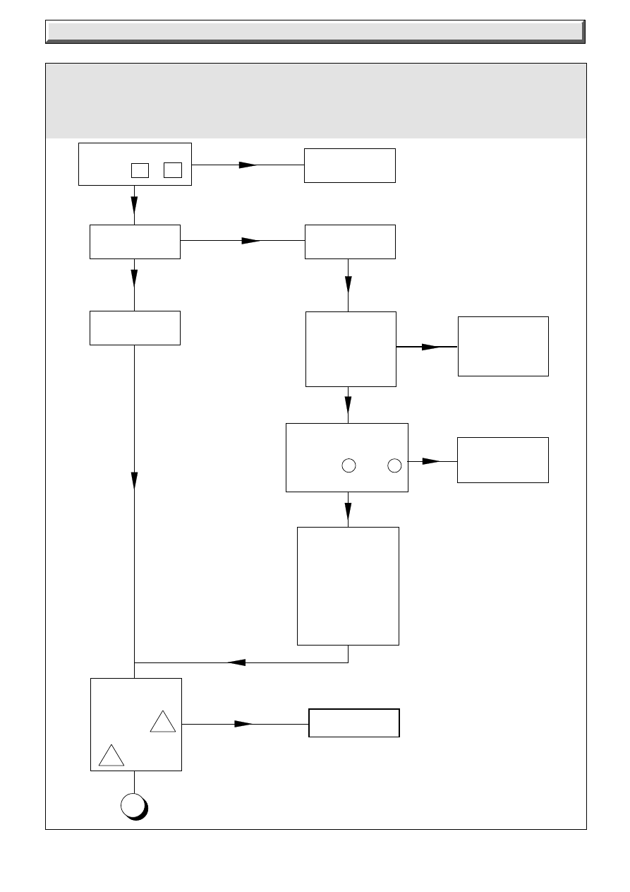
28
221837B
Diagram 13.1
13 Fault Finding
Before detailed checking of electrical components ensure that remote controls are calling for heat.
Check that the gas supply is free of obstructions and purged of air. Check the overheat thermostat
and fluehood thermostat have not operated. Isolate the electrical supply and physically check
ALL cables, connections and the printed circuit board (PCB) fuse. Check the air tubes to air
pressure switch.
Is there 240V
between L + N
Isolate supply
Check continuity
of overheat
thermostat.
Thermostat ok ?
Is thermostat
neon on ?
Correct power
supply problem
Isolate supply
1
Is there
continuity
between
NC
and
C
on APS
Replace APS
Check continuity of
control thermostat
between 3 and 6
ok ?
Replace control
thermostat
NO
YES
YES
Check wiring
and IC PCB
'stat' plug for
defects.
Repair or
replace wiring/
PCB if
necessary
YES
YES
NO
NO
NO
Replace
overheat
thermostat
NO
YES
29
221837B
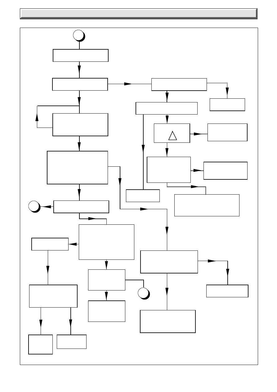
13 Fault Finding
Has boiler been
operating for 10
seconds yet ?
Does gas ignite ?
2
YES
NO
YES
Isolate supply
NO
Replace PCB
Examine electrode and
leads. Repair/replace
as necessary
Reconnect supply
Is APS neon lit ?
Is fan running ?
Replace APS
1
Is there 240V at the fan ?
Replace ignition
PCB
Flue hood overheating-
blocked secondary heat
exchanger (clean/replace)
Replace flue hood
thermostat
Will flue hood
thermostat reset?
- is there 240V at
the fan?
Is there 240V
at C ?
YES
YES
NO
NO
YES
NO
NO
Replace fan
Switch High/Low Switch
to 'low'
Is there a spark at
electrode ?
Can the “low” gas
pressure be set
(see data tables)
at test point on gas
valve?
YES
NO
YES
Diagram 13.1
NO
Check continuity of
both main coils
Coils ok?
Replace
ignition
PCB
Replace as
necessary
YES
NO
YES
NO
YES
NO
NO
Does gas
ignite?
Faulty injector
Replace
NO
3
YES
Does discharge tube on
ignition PCB flash ?
30
221837B
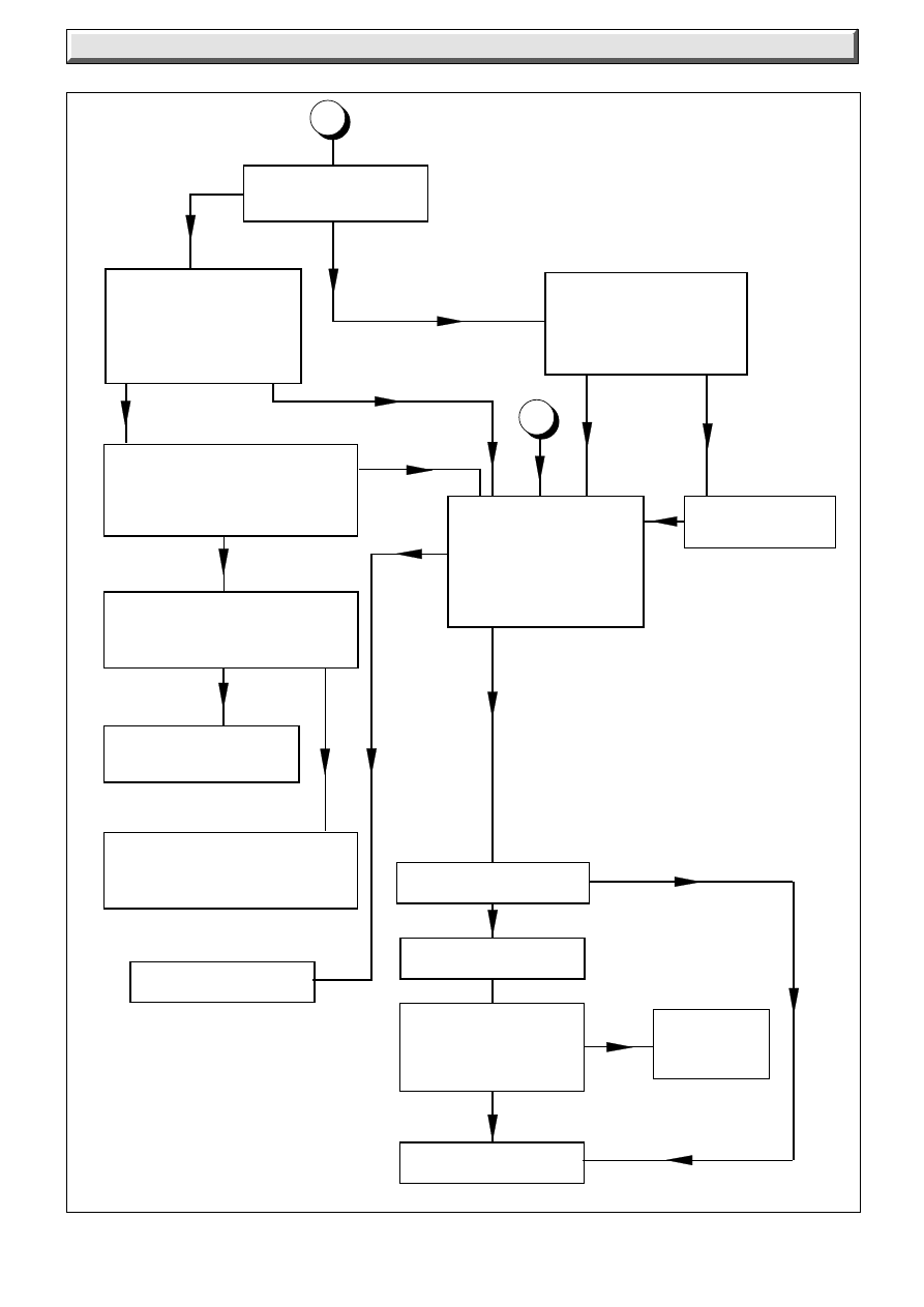
13 Fault Finding
Diagram 13.1
Does the burner
remain alight ?
Isolate supply
Check continuity
between 4 and 1 on
High/Low switch.
Switch ok ?
Replace
High/Low
switch
NO
YES
2
Replace gas valve
YES
NO
NO
YES
NO
NO
Turn High/Low switch to
“High”.
Check and adjust “High”
gas pressure
(see data tables)
Is gas pressure OK?
Adjust gas
pressure
Does “High” neon light ?
Is condense drain
blocked, repair.
Does burner remain
alight ?
Is the low gas pressure
setting correct (see Data
Tables) at the test point
on the gas valve ?
NO
YES
3
YES
YES
YES
NO
Boiler satisfactory
Is the low gas pressure setting
correct (see data tables)?
Adjust as necessary.
Does burner remain alight?
Will burner remain alight if gas
pressure is temporarily
increased?
NO
Faulty injector - Replace
(Reset pressure)
YES
Faulty PCB flame detection -
Replace PCB
(Reset pressure)
31
221837B
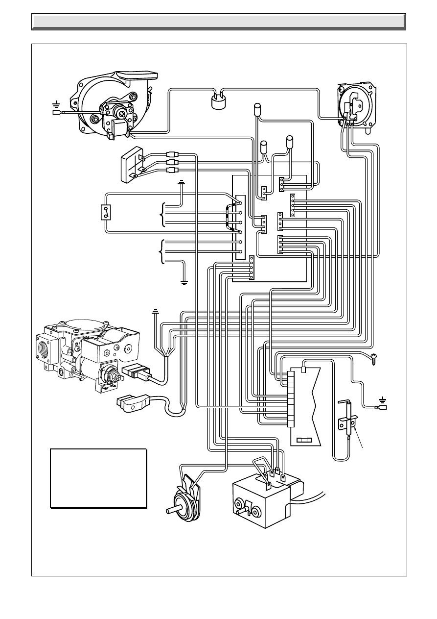
Diagram 13.2
13 Fault Finding
9024
b
1
2
3
4
5
6
7
8
9
10
KEY:
b - BLUE
bk - BLACK
br - BROWN
g/y - GREEN/
YELLOW
g - GREY
SL
PL
PN
1
L
N
FAN
AIR PRESSURE
SWITCH
EARTH
POST
MAINS
240VAC
50Hz
PUMP
SUPPLY
EARTH
POST
CHASSIS
EARTH
CONDENSE
CUT-OFF
SPARK
ELECTRODE
OVERHEAT
CUT-OFF
BOILER CONTROL
THERMOSTAT
2 AMP
FUSE
CONTROL
P.C.B.
HIGH/LOW
(FLAME)
SWITCH
DEMAND
NEON
LOW
FLAME
NEON
MAIN
PLUG
HIGH/LOW
(FLAME) PLUG
INTER-
CONNECTION
P.C.B.
PLASTIC
OVERHEAT
HIGH
FLAME
NEON
RED
LINK
*
MULTI-FUNCTIONAL
CONTROL
*
REMOVE RED LINK IF REMOTE
SWITCH IS TO BE FITTED
REMOTE
SWITCH
TB1
LAMP
LAMP
N
GV1
GV2
CM1
STAT
PCB
w
r
y
y
br
p
br
y
g/y
o
r
p
bk
w
b
g/y
br
bk
b
br
g/y
b
br
r
r
g/y
br
b
p
p
r
r
w
w
bk
bk
g/y
g
bk
b
bk
bk
r
br
y
g
3
2
1
3
1
2
3
1
2
1
2
3
1
2
3
1
2
4
3
1
2
4
r
- RED
y
- YELLOW
p - PURPLE
w - WHITE
o - ORANGE
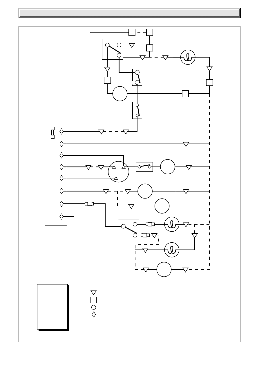
32
221837B
13 Fault Finding
Diagram 13.3
554
8
I.C. P.C.B. CONNECTIONS: ie STAT (Pin No. from bottom)
PLASTIC
OVERHEAT
CONTROL
THERMOSTAT
FAN
NO
C
NC
MAIN TERMINAL STRIP CONNECTIONS
CONTROL THERMOSTAT CONNECTIONS
PRINTED CIRCUIT BOARD CONNECTIONS
9
8
7
PUMP
PUMP
OVERRUN
✽
RED LINK MAY HAVE BEEN
REMOVED TO FIT REMOTE CONTROLS
3
1
4
OVERHEAT
THERMOSTAT
PL
SL
I
L
PN
N
AIR PRESSURE
SWITCH
✽
RED LINK
FUSE
TYPE F2A
IGNITION
P.C.B.
GV
B1
GV
B2
GV
2
LOW FLAME NEON
Lamp N(2)
HIGH FLAME
NEON
Lamp(1)
HIGH/LOW
SWITCH
CONDENSE
CUT-OFF
Amp Con
Stat(2)
Lamp
N(1)
Stat(4)
Lamp(3)
Lamp
N(3)
DEMAND
NEON
Stat(1)
P.C.B.(2)
P.C.B.(4) CM1(1)
P.C.B.(1)
8
1
10
6
9
5
2
7
CM1(2)
P.C.B.(3)
GV1(1)
GV1(3)
GV1(2)
GV2(1 )
GV2(2)
y
y
w
r
r
b
br
bk
y
w
p
b
br
bk
br
b
Stat(3)
KEY:
r - RED
br - BROWN
p - PURPLE
b - BLUE
bk - BLACK
y - YELLOW
w - WHITE
g - GREY
br
p
bk
b
bk
3
6
g
g
bk
bk
p
r
r
w
w
CM1(3)
r
bk
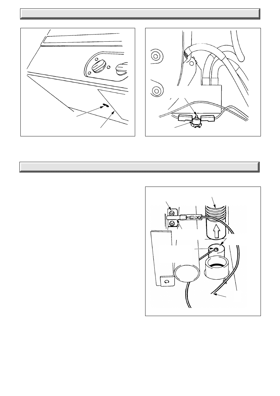
33
221837B
Diagram 13.5
Diagram 13.4
14 Replacement of Parts
13 Fault Finding
4067 S
FLUE HOOD
OVERHEAT
THERMOSTAT
RESET
BUTTON
Notes:
Replacement of parts must be carried out by a competent
person.
Before replacing any parts isolate the boiler from the electrical
supply and turn the gas supply off at the gas service cock, see
diagram 8.1.
Unless stated otherwise, all parts are replaced in the reverse
order to removal.
After replacing any parts always test for gas soundness and if
necessary carry out functional check of controls.
For the following the front case and inner case cover will need
to be removed, diagrams 5.2 and 5.3.
14.1 Spark Electrode
Replace as described in Section 12.4.
14.2 Ignition Lead: diagram 14.2
Release the control box as Section 9.
To disconnect the ignition lead from the control board, remove
the PCB from the mounting pegs, the front two have detachable
grips, the rear two are plain supports.
When refitting lead make sure that there is enough length
through the gland plate assembly.
Condensate Sensor - diagram 14.2
Refer to the relevant parts of Section 14.2 to remove the screw.
The sensing screw is fitted to a push fit cap which can be levered
off for easy access.
Note. The condensate flexible tube is a push fit and can be
removed from the condensate drain trap to improve access to
the screw.
When replacing the cap make sure that it is firmly in place and
that the ring tag is pointing away from the casing side.
Diagram 14.2
IGNITION
SENSING
LEAD
5549
SECURING
SCREW (2)
CONDENSATE FLEXIBLE
TUBE
SPARK
ELECTRODE
CONDENSATE
DRAIN CAP
CONDENSATE
SENSOR
SCREW
RESET BUTTON
INSTRUCTION LABEL
7891
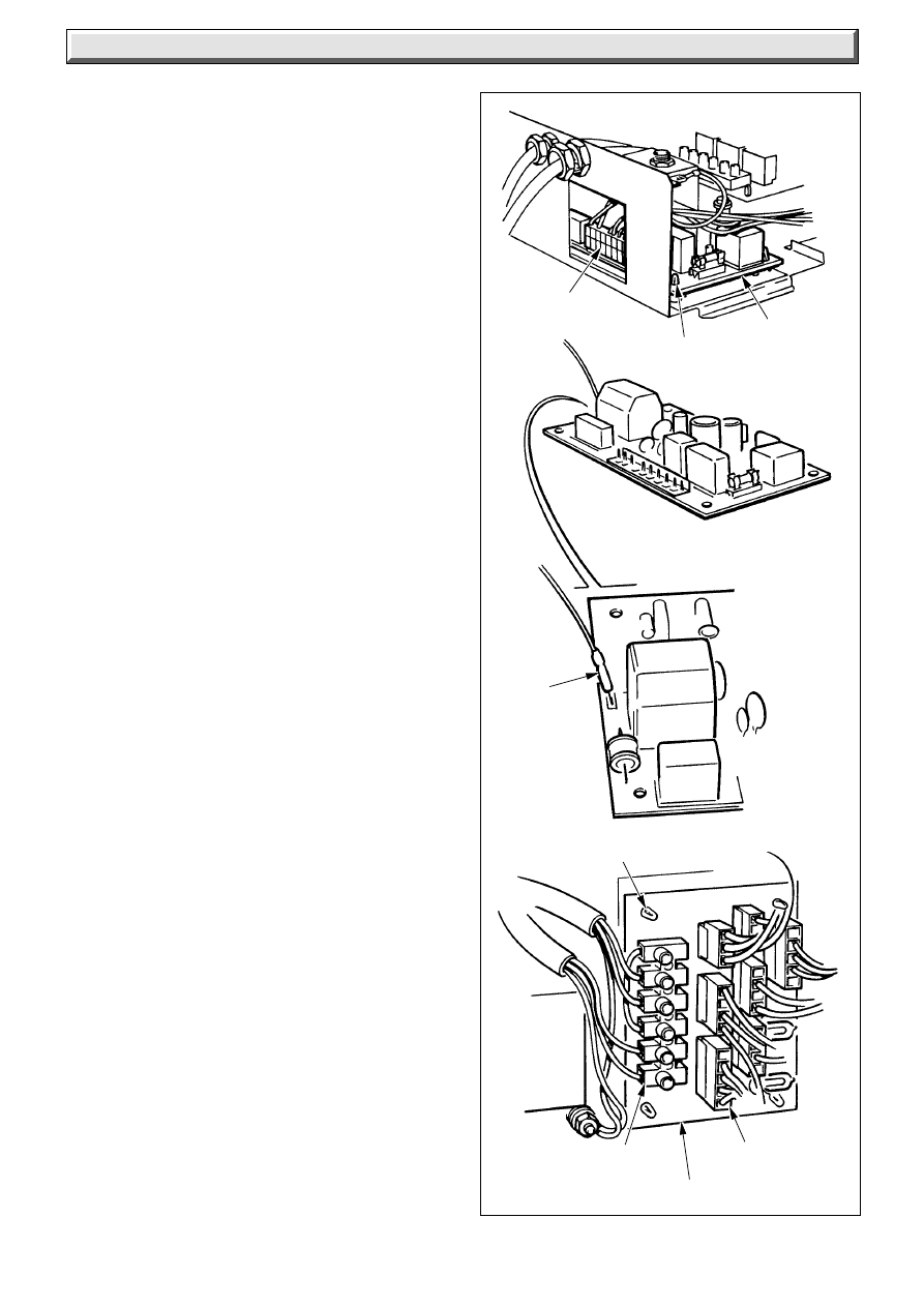
34
221837B
Diagram 14.3
14 Replacement of Parts
4065 S
ELECTRICAL
PLUG
SUPPORT
POST (2)
CONTROL
P.C.B.
IGNITION
LEAD
SUPPORT POST (4)
TERMINAL
STRIP
I.C.B
ELECTRICAL
PLUG (5)
Control PCB: diagram 14.3 (top)
Disconnect the electrical plug on the board.
Release from its two support posts and carefully pull the board
away noting that the ignition lead is still connected.
It may be necessary to hold some of the wires above the PCB
clear with an electrical screwdriver on removal or refitting.
Release and carefully pull the board away from its supports,
noting that the ignition lead is still connected.
Disconnect the ignition lead.
Interconnecting PCB: (ICB) diagram 14.3
(bottom)
Disconnect the electrical plugs and cables from the terminal
strip.
Release and carefully pull the board away from its supports.
When refitting refer to wiring diagram 13.2.
14.4 Control Thermostat and Overheat Cutoff
Release the control box, see Section 9.
Control Thermostat: diagram 14.4A and 14.4
Pull off the control thermostat and High/Low knobs.
Remove the three fascia securing screws and fascia.
Remove the electrical connections from the control thermostat
body.
Remove the two control thermostat securing screws.
Release and remove the control thermostat phial from the
pocket.
Withdraw the capillary through the controls box grommet.
Slide control thermostat body away from control box.
On replacement smear the phials with the heat sink compound
supplied before replacing in the phial pocket.
When refitting refer to wiring diagram 13.2.
Overheat Cutoff: diagram 14.4A and 14.4
Remove the electrical connections.
Remove the locking nut.
Release and remove the overheat cutoff phial from the pocket.
Withdraw the capillary through the controls box grommet.
On replacement smear the phials with the heat sink compound
supplied before replacing in the phial pocket.
When refitting refer to wiring diagram 13.2.
Neatly secure any surplus capillary.
Flue Hood Overheat Cutoff: diagram 14.5
Remove electrical connections and unfasten the screws to
release.
Note: the polarity of the connections is not important.
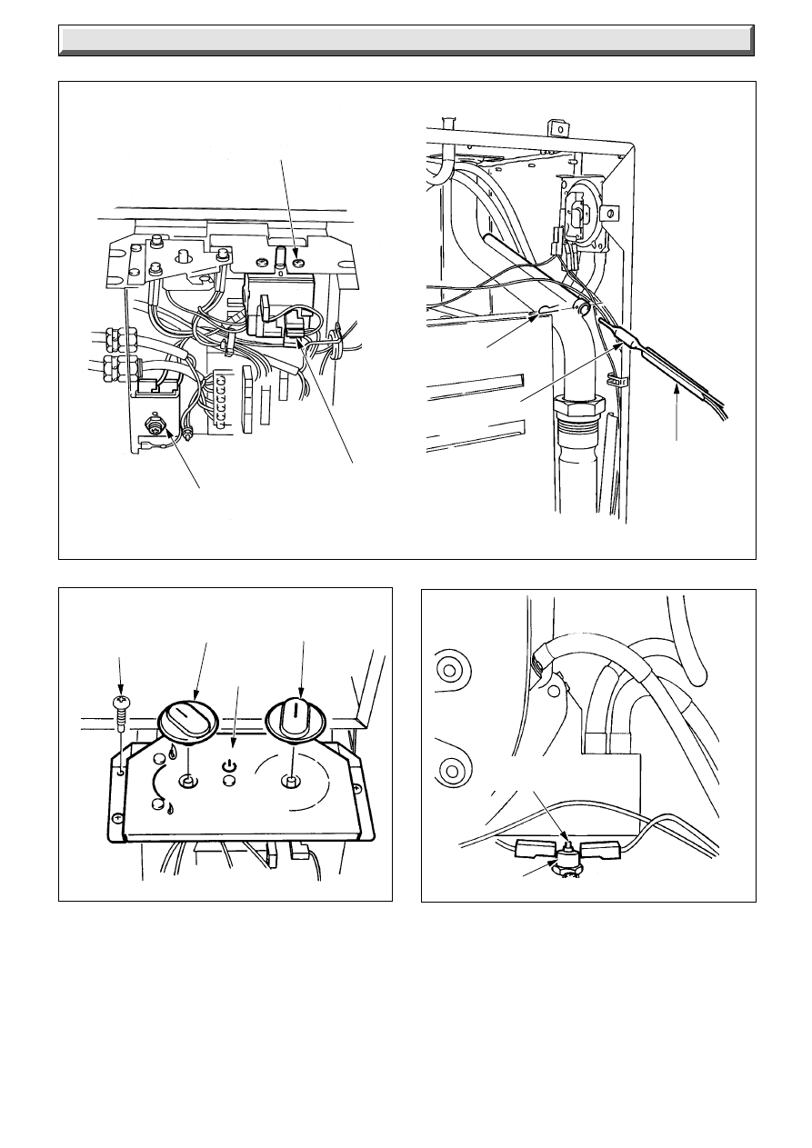
35
221837B
Diagram 14.4
Diagram 14.4A
14 Replacement of Parts
Diagram 14.5
4067 S
4078 S
4377 S
4066 S
CONTROL THERMOSTAT
SECURING SCREW (2)
OVERHEAT
CUT OFF
LOCKNUT
ELECTRICAL
CONNECTION (5)
RETAINING
PIN
OVERHEAT CUT
OFF PHIAL
CONTROL
THERMOSTAT
PHIAL
RESET
BUTTON
PLASTIC
OVERHEAT
THERMOSTAT
CONTROLS
FASCIA
SECURING
SCREW (3)
CONTROL
THERMOSTAT
KNOB
HIGH/LOW
CONTROL
KNOB
CONTROLS
FASCIA
14.5 “High/Low” Control: diagram 14.4 and
14.6
Remove the fascia as described in Section 14.4.
Remove the four screws securing the lights bracket.
Remove the locknut to release the “High/Low” control.
Disconnect the three in-line electrical connectors.
When refitting refer to wiring diagram 13.2.
14.6 Air Pressure Switch: diagram 14.7.
Remove the air pressure tubes and electrical connections.
Remove the two securing screws to release the air pressure
switch.
When fitting the replacement make sure that all the air pressure
tubes and electrical connections are made as shown.
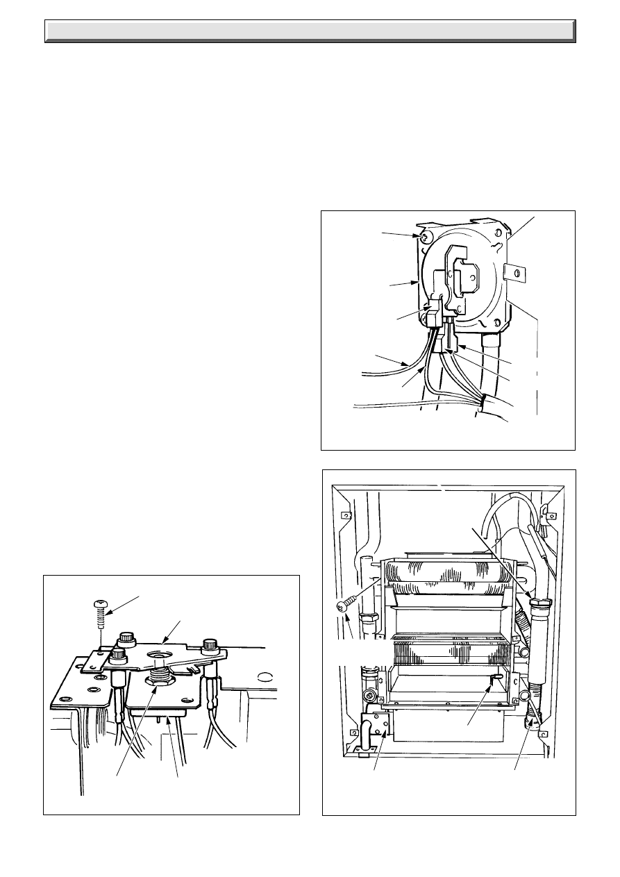
36
221837B
Diagram 14.8
4379 S
CONDENSATE
TUBE
SECURING
SCREWS (6)
SPARK
ELECTRODE
INJECTOR MANIFOLD
UNION
CONNECTION
Diagram 14.7
14 Replacement of Parts
ELECTRICAL
CONNECTIONS (3)
4378 S
SECURING
SCREW (4)
LIGHTS BRACKET
LOCKNUT
Diagram 14.6
HIGH/LOW CONTROL
SECURING
SCREW (2)
AIR
PRESSURE
SWITCH
GREY
GREY
YELLOW
BROWN
CLEAR
RED
AIR PRESSURE SWITCH TUBES
4068 S
14.7 Multifunctional Control: diagram 8.1.
Disconnect the screws and electrical plugs at the multifunctional
control.
Support the multifunctional control and remove the four screws
from the flanged connection, undo the union at the gas service
cock and remove the support bracket securing screw.
Remove the multifunctional control by easing the flange and
service cock apart.
Remove the union half and refit to the replacement multifunctional
valve.
Use a little jointing compound on the external thread only, to
ensure gas soundness.
Make sure that the new “O” ring is in place in the flanged
connection is replaced.
It will be necessary to purge the pipework and multifunctional
control before relighting and checking the pressure, refer to
“Commissioning”.
14.8 Fan
Refer to Section 12.1 “Heat Exchanger Cleaning”.
Make sure that the earth connection is remade onto the
replacement fan.
The polarity of the electrical connections is not important.
14.9 Injector
Refer to Servicing Section 12.3.
Fit new injector as shown.
Note: The replacement injector manifold is supplied complete
with the gas supply pipe manifold.
14.10 Heat Exchanger: diagram 14.8
Note: To carryout the following operations it will be found more
convenient if the whole of the heat exchanger and burner are
removed as a unit.
Follow the relevant parts of Servicing Section and remove the
bypass heat shield, fan/flue hood, combustion chamber front
panel, heat exchanger baffle, spark electrode, injector manifold
and thermostat phials.
Release the flexible tube from the condense drain trap, this is
a push-fit.
Release union connections and the six securing screws, then
remove the complete assembly.
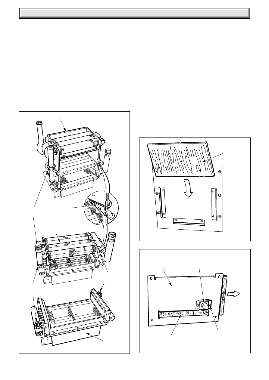
37
221837B
14 Replacement of Parts
Heat Exchanger: Secondary - diagram 14.9
Disconnect the union connector.
Remove and fit the flexible hose to the replacement.
Heat Exchanger - Primary - diagram 14.10
Disconnect the three union connections.
14.11 Burner: diagram 14.9
Note: To carryout the following operations it will be found more
convenient if the whole of the heat exchanger and burner are
removed as a unit.
Follow the relevant parts of Servicing Section and remove the
bypass heat shield, fan/flue hood, combustion chamber front
panel, heat exchanger baffle, spark electrode, injector and
thermostat phials.
Diagram 14.9
4380 S
SECONDARY HEAT EXCHANGER
UNION
CONNECTION
LOCATING
SLOT
PRIMARY HEAT
EXCHANGER
UNION
CONNECTION
UNION
CONNECTION
BURNER
Release the flexible tube from the condense drain trap, this is
a push-fit.
Release union connections and the six securing screws, then
remove the complete assembly.
Remove the insulation as Section 14.14 and retain for use in the
replacement part.
Disconnect the two union connections.
Fit the insulation.
14.12 Insulation - Rear - diagram 14.10
With the heat exchangers and burner assembly removed, as
Sections 14.10 and 14.11, the rear insulation pad can be
removed as shown.
14.13 Insulation: Combustion Chamber Front
Panel: diagram 14.11
Remove the two screws from the viewing window then slide the
insulation pad out.
Diagram 14.10
Diagram 14.11
4381 S
4073 S
REAR
INSULATION
COMBUSTION
CHAMBER
FRONT
PANEL
PILOT
VIEWING
WINDOW
INSULATION
SECURING
SCREW (2)
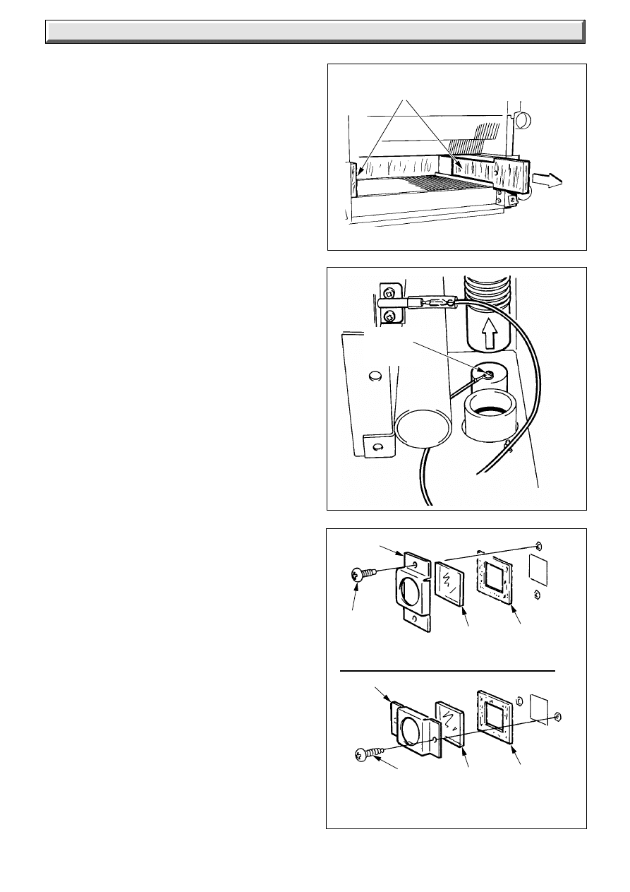
38
221837B
Diagram 14.13
Diagram 14.12
Diagram 14.14
VIEWING WINDOW/INNER CASE
GASKET
VIEWING WINDOW/COMBUSTION
CHAMBER FRONT PANEL
14 Replacement of Parts
SIDE INSULATION
4382 S
5549
4076 S
FRAME
SECURING
SCREW (2)
GLASS
FRAME
SECURING
SCREW (2)
GLASS
GASKET
CONDENSATE
SENSOR
SCREW
14.14 Insulation - Sides - diagram 14.12
Remove the spark electrode refer to Section 12.4.
Remove the insulation by sliding it out.
14.15 Condensate Sensor: diagram 14.13
Refer to the relevant parts of Section 14.2 to remove the screw.
The sensing screwis fitted to a push fit cap which can be levered
off for easy access.
Note. The condensate flexible tube is a push fit and can be
removed from the condensate drain trap to improve access to
screw.
When replacing the cap make sure that the ring tag is pointing
away from th casing side.
14.16 Viewing Window Glass: diagram 14.14
Remove the two screws to release the frame and glass.
When replacing take care not to damage the gasket.
14.17 Inner Case Cover Seal
When removing seal make sure that all the old adhesive is
removed.
When fitting the new seal make sure that it fits correctly and has
not buckled.
14.18 Fascia and Lights Assembly
Release the control box as Section 9.
Refer to the relevant parts of Section 14.5 to remove the fascia
and lights bracket.
39
221837B
15 Spare Parts
Description
Part No.
GC Part No.
Key No.
15 Spare Parts
When ordering spare parts, please quote the appliance name
and serial number, to be found on the data label, visible when
the outer casing is removed.
If ordering from Birtish Gas also quote the GC number of the
part.
1
230530
Multifunctional control
2
800476
Thermostat - control
278 094
3
800477
Thermostat - over heat cutoff
278 095
4
800466
Overheat Thermostat
278047
5
450260
High/low control
278 276
6
800467
Thermostat control knob
278 049
7
202135
Air pressure switch
313 303
8
203157P
Gas manifold assembly - 80 - NAT
278 262
8
203160P
Gas manifold assembly - 70 - NAT
278 519
9
202231
Fuse
10
208302
Sight glass
312 419
208093
Gasket-sight glass (not illustrated)
312 420
11
800840
Ignition lead
E00335
12
202211
Control board (PCB)
379 239
13
800659
Fan
278 263
14
202625
Electrode
278 096
15
202210
Interconnection board
379 238
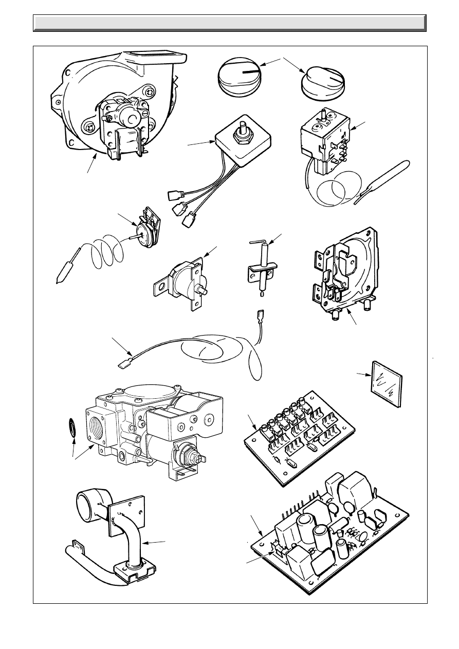
40
221837B
Diagram 15.1
15 Spare Parts
3
6291
13
5
2
14
7
15
10
12
8
9
6
11
4
Because of our constant endeavour for improvement details may vary slightly from those in the instructions.
1
Wyszukiwarka
Podobne podstrony:
Glow Worm installation and service manual Energy Saver 80 UI
Glow Worm installation and service manual Energy Saver 60 UI
Glow Worm installation and service manual Energy Saver 40 UI
Glow Worm installation and service manual Energy Saver 60 UI
Glow Worm installation and service manual Energy Saver 40 UI
Glow Worm installation and service manual Hideaway 70CF UIS
Glow Worm installation and service manual Ultimate 50CF UIS
Glow Worm installation and service manual Ultimate 60CF UIS
Glow Worm installation and service manual Glow micron 60
Glow Worm installation and service manual Glow micron 40
Glow Worm installation and service manual Hideaway 80BF UIS
Glow Worm installation and service manual Hideaway 50CF
Glow Worm installation and service manual Hideaway 120BF UIS
Glow Worm installation and service manual Hideaway 120CF UIS
Glow Worm installation and service manual 45 BBU 2
Glow Worm installation and service manual Ultimate 40CF UIS
Glow Worm installation and service manual Glow micron 70
więcej podobnych podstron