About the EdgeCAM Simulator
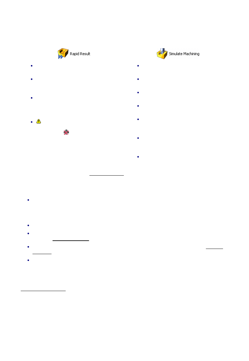
The EdgeCAM Simulator has two modes, that you start from their buttons in EdgeCAM's Main toolbar (for
example):
Use mainly with mould and die parts and
surface parts.
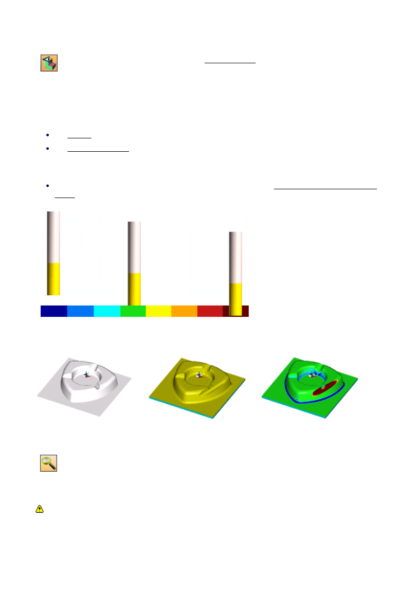
Gives you almost instant toolpath verification
with visual comparison between machined
stock and original model.
Not recommended for production machining
and does not support the simulation of
indexing, rotary machining, turning or
undercut machining (eg, thread milling).
Collision checking slows down Rapid
Result considerably, so you should disable it
in the toolbar (
) unless necessary.
Use mainly for milling, multiplane milling, 2
axis, 4 axis and C & Y axis turning.
Tool, tool holder and fixtures are included
in the simulation.
Gives a very realistic representation of the
process.
Speed can be controlled and the view
dynamically rotated, zoomed and panned.
For turning operations, the part can be
shown as a ¾ view enabling internal
operations to be viewed clearly.
Not recommended for surface parts with
very complex toolpaths (simulation might
be very slow).
Gives you toolpath verification with visual
comparison between machined stock and
original model.
See a comparative table of features in each mode.
Please note that EdgeCAM Simulator:
EdgeCAM Simulator aims to show you the finished part that the output CNC code will produce. When
Cutter Radius Compensation is to be applied on the machine (that is when the 'Pathcomp' setting is
not used), this must be done correctly for the finished part to match the part shown in EdgeCAM
Simulator.
EdgeCAM Simulator is available in GLview only.
EdgeCAM Simulator is not strictly time-based, so twin turret simulations may lose synchronisation.
There are steps you can take to counter this.
EdgeCAM Simulator supercedes the EdgeCAM Verify product. For further details see the Verifying
the Model topic (in the Obsolete book of the online User Guide).
You may encounter problems if you output EdgeCAM surfaces as STL then use the STL file to create
digitised stock. This is because the triangles in a collection of surfaces might not be closed, whereas
stock from solids should be.
See Also:
Sub-spindle Simulation.
1
EdgeCAM User Guide
About the EdgeCAM Simulator
The EdgeCAM Simulator has two modes, that you start from their buttons in EdgeCAM's Main toolbar (for
example):
Use mainly with mould and die parts and
surface parts.
Gives you almost instant toolpath verification
with visual comparison between machined
stock and original model.
Not recommended for production machining
and does not support the simulation of
indexing, rotary machining, turning or
undercut machining (eg, thread milling).
Collision checking slows down Rapid
Result considerably, so you should disable it
in the toolbar (
) unless necessary.
Use mainly for milling, multiplane milling, 2
axis, 4 axis and C & Y axis turning.
Tool, tool holder and fixtures are included
in the simulation.
Gives a very realistic representation of the
process.
Speed can be controlled and the view
dynamically rotated, zoomed and panned.
For turning operations, the part can be
shown as a ¾ view enabling internal
operations to be viewed clearly.
Not recommended for surface parts with
very complex toolpaths (simulation might
be very slow).
Gives you toolpath verification with visual
comparison between machined stock and
original model.
See a comparative table of features in each mode.
Please note that EdgeCAM Simulator:
EdgeCAM Simulator aims to show you the finished part that the output CNC code will produce. When
Cutter Radius Compensation is to be applied on the machine (that is when the 'Pathcomp' setting is
not used), this must be done correctly for the finished part to match the part shown in EdgeCAM
Simulator.
EdgeCAM Simulator is available in GLview only.
EdgeCAM Simulator is not strictly time-based, so twin turret simulations may lose synchronisation.
There are steps you can take to counter this.
EdgeCAM Simulator supercedes the EdgeCAM Verify product. For further details see the Verifying
the Model topic (in the Obsolete book of the online User Guide).
You may encounter problems if you output EdgeCAM surfaces as STL then use the STL file to create
digitised stock. This is because the triangles in a collection of surfaces might not be closed, whereas
stock from solids should be.
See Also:
Sub-spindle Simulation.
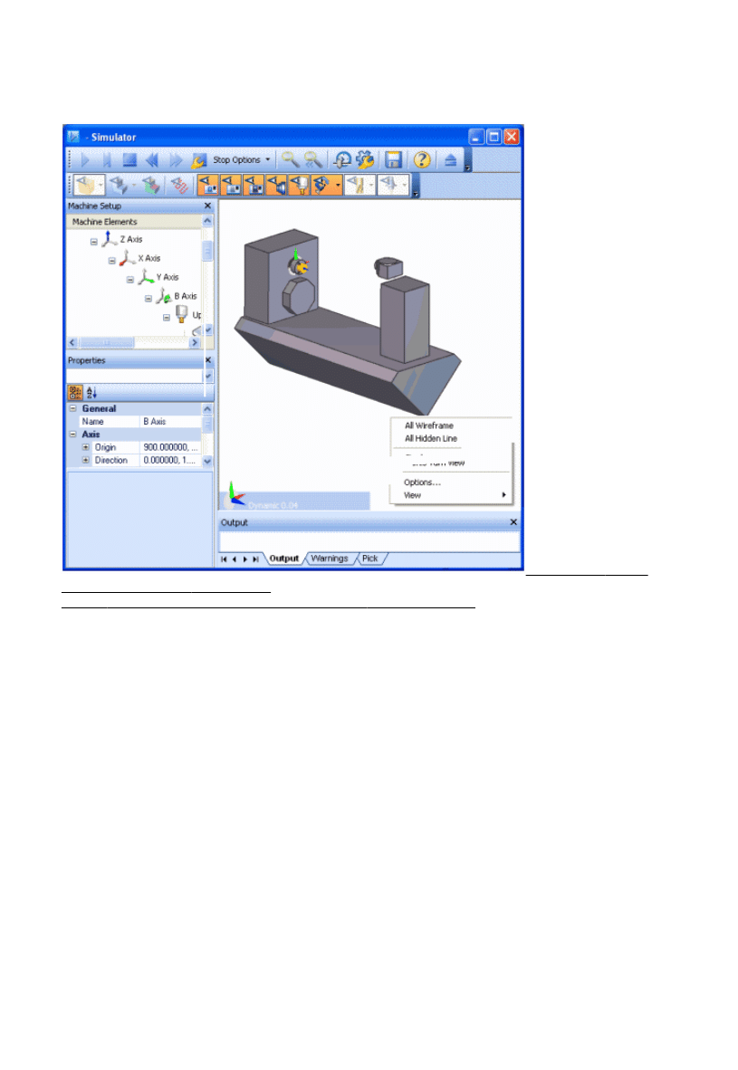
The Simulator User Interface
In the illustration of a typical Simulator window setup below, click on a red caption for more information.
Main Toolbar Display
Toolbar Graphics Area Machine Tree
Window
View Caption Output Window Shortcut Menu Properties Window
2
EdgeCAM User Guide
About the EdgeCAM Simulator
The EdgeCAM Simulator has two modes, that you start from their buttons in EdgeCAM's Main toolbar (for
example):
Use mainly with mould and die parts and
surface parts.
Gives you almost instant toolpath verification
with visual comparison between machined
stock and original model.
Not recommended for production machining
and does not support the simulation of
indexing, rotary machining, turning or
undercut machining (eg, thread milling).
Collision checking slows down Rapid
Result considerably, so you should disable it
in the toolbar (
) unless necessary.
Use mainly for milling, multiplane milling, 2
axis, 4 axis and C & Y axis turning.
Tool, tool holder and fixtures are included
in the simulation.
Gives a very realistic representation of the
process.
Speed can be controlled and the view
dynamically rotated, zoomed and panned.
For turning operations, the part can be
shown as a ¾ view enabling internal
operations to be viewed clearly.
Not recommended for surface parts with
very complex toolpaths (simulation might
be very slow).
Gives you toolpath verification with visual
comparison between machined stock and
original model.
See a comparative table of features in each mode.
Please note that EdgeCAM Simulator:
EdgeCAM Simulator aims to show you the finished part that the output CNC code will produce. When
Cutter Radius Compensation is to be applied on the machine (that is when the 'Pathcomp' setting is
not used), this must be done correctly for the finished part to match the part shown in EdgeCAM
Simulator.
EdgeCAM Simulator is available in GLview only.
EdgeCAM Simulator is not strictly time-based, so twin turret simulations may lose synchronisation.
There are steps you can take to counter this.
EdgeCAM Simulator supercedes the EdgeCAM Verify product. For further details see the Verifying
the Model topic (in the Obsolete book of the online User Guide).
You may encounter problems if you output EdgeCAM surfaces as STL then use the STL file to create
digitised stock. This is because the triangles in a collection of surfaces might not be closed, whereas
stock from solids should be.
See Also:
Sub-spindle Simulation.
Working with the Windows
EdgeCAM Simulator features:
The Output Window.
The Machine Setup and Properties windows. You use these windows to control Machine Tool
Simulation. See Machine Tool Simulation for more details.
You can show and hide windows.
And you can move, dock or undock a window:
Start to drag the window around the Simulator window:
For non-tabbed windows drag the window by its title area at the top.
For tabbed windows drag by the title area at the top to move all the windows at once.
Alternatively drag individual windows by their tab title, at the bottom.
1.
As soon as you start to drag, some handles appear. Each handle docks at either the top, bottom, left
or right edge of the overall Simulator window (or inside another window - see below). To dock, hover
over one of these handles and drop.
To give you a preview, an overlaid colour shows you the position the window will occupy, as you
hover over each handle.
2.
To move or undock the window, simply re-position it without using the handles.
3.
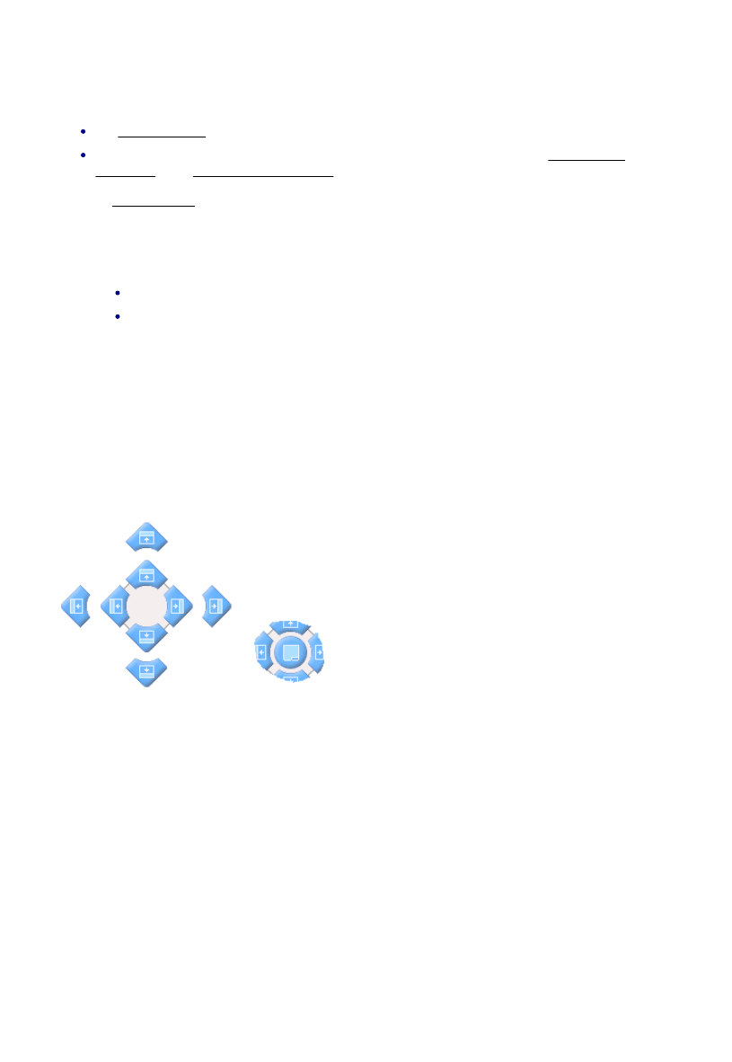
When dragging a window, there are 'outer' handles right at the edges of the Simulator window, and 'inner'
handles.
The outer handles move or re-size existing windows as necessary to
make room for the new window position.
The inner handles fit the window into any available empty space along
the edge, or split existing window space to make room for the window,
as necessary.
As you hover over an existing window, a central handle
appears that docks the window at the same place,
producing tabs to switch between them.
3
EdgeCAM User Guide

About the EdgeCAM Simulator
The EdgeCAM Simulator has two modes, that you start from their buttons in EdgeCAM's Main toolbar (for
example):
Use mainly with mould and die parts and
surface parts.
Gives you almost instant toolpath verification
with visual comparison between machined
stock and original model.
Not recommended for production machining
and does not support the simulation of
indexing, rotary machining, turning or
undercut machining (eg, thread milling).
Collision checking slows down Rapid
Result considerably, so you should disable it
in the toolbar (
) unless necessary.
Use mainly for milling, multiplane milling, 2
axis, 4 axis and C & Y axis turning.
Tool, tool holder and fixtures are included
in the simulation.
Gives a very realistic representation of the
process.
Speed can be controlled and the view
dynamically rotated, zoomed and panned.
For turning operations, the part can be
shown as a ¾ view enabling internal
operations to be viewed clearly.
Not recommended for surface parts with
very complex toolpaths (simulation might
be very slow).
Gives you toolpath verification with visual
comparison between machined stock and
original model.
See a comparative table of features in each mode.
Please note that EdgeCAM Simulator:
EdgeCAM Simulator aims to show you the finished part that the output CNC code will produce. When
Cutter Radius Compensation is to be applied on the machine (that is when the 'Pathcomp' setting is
not used), this must be done correctly for the finished part to match the part shown in EdgeCAM
Simulator.
EdgeCAM Simulator is available in GLview only.
EdgeCAM Simulator is not strictly time-based, so twin turret simulations may lose synchronisation.
There are steps you can take to counter this.
EdgeCAM Simulator supercedes the EdgeCAM Verify product. For further details see the Verifying
the Model topic (in the Obsolete book of the online User Guide).
You may encounter problems if you output EdgeCAM surfaces as STL then use the STL file to create
digitised stock. This is because the triangles in a collection of surfaces might not be closed, whereas
stock from solids should be.
See Also:
Sub-spindle Simulation.
Working with the Toolbars
The User Interface of EdgeCAM Simulator features:
The Main toolbar.
The Display toolbar.
You can:
Show or hide a toolbar.
'Dock' a toolbar at the edge of the Graphics Area, or you can 'undock' it, when it freely floats in the
Graphics Area.
Move a toolbar.
4
EdgeCAM User Guide

About the EdgeCAM Simulator
The EdgeCAM Simulator has two modes, that you start from their buttons in EdgeCAM's Main toolbar (for
example):
Use mainly with mould and die parts and
surface parts.
Gives you almost instant toolpath verification
with visual comparison between machined
stock and original model.
Not recommended for production machining
and does not support the simulation of
indexing, rotary machining, turning or
undercut machining (eg, thread milling).
Collision checking slows down Rapid
Result considerably, so you should disable it
in the toolbar (
) unless necessary.
Use mainly for milling, multiplane milling, 2
axis, 4 axis and C & Y axis turning.
Tool, tool holder and fixtures are included
in the simulation.
Gives a very realistic representation of the
process.
Speed can be controlled and the view
dynamically rotated, zoomed and panned.
For turning operations, the part can be
shown as a ¾ view enabling internal
operations to be viewed clearly.
Not recommended for surface parts with
very complex toolpaths (simulation might
be very slow).
Gives you toolpath verification with visual
comparison between machined stock and
original model.
See a comparative table of features in each mode.
Please note that EdgeCAM Simulator:
EdgeCAM Simulator aims to show you the finished part that the output CNC code will produce. When
Cutter Radius Compensation is to be applied on the machine (that is when the 'Pathcomp' setting is
not used), this must be done correctly for the finished part to match the part shown in EdgeCAM
Simulator.
EdgeCAM Simulator is available in GLview only.
EdgeCAM Simulator is not strictly time-based, so twin turret simulations may lose synchronisation.
There are steps you can take to counter this.
EdgeCAM Simulator supercedes the EdgeCAM Verify product. For further details see the Verifying
the Model topic (in the Obsolete book of the online User Guide).
You may encounter problems if you output EdgeCAM surfaces as STL then use the STL file to create
digitised stock. This is because the triangles in a collection of surfaces might not be closed, whereas
stock from solids should be.
See Also:
Sub-spindle Simulation.
Setting Options
In the Main toolbar click
and make settings in the Options dialog that opens.
(You can also open this dialog from the Simulator Shortcut menu.)
Many of the options are explained within the dialog itself; here are some additional notes where needed:
General tab
Use EdgeCAM View - Check this for EdgeCAM Simulator to open with the same view selected as
EdgeCAM.
Maximised - The simulator window will occupy the whole of the screen, until you use Minimize or
Restore Down (in the top right hand corner).
Always on top - The simulator window will be on top of the windows for other applications, until you
use Minimize (in the top right hand corner).
Toolpath/Stock/Fixture Color - Can be set to be the same color as EdgeCAM, or another color.
Metallic - Renders stock surfaces with metallic look (see an example).
Background Colour 1 - The background colour for the top of the Graphics area, blending into...
Background Colour 2 - The background colour for the bottom of the Graphics area.
Display tab (restart the Simulator after changing these options)
Enable Swap Area - Update the smallest area of the screen possible, to increase performance.
Software Render - Bypass your graphics card's OpenGL acceleration. You should leave this
unchecked for faster rendering, unless you have problems with your graphics card driver.
Accelerated Rendering - Check this to speed up solids rendering, by using the acceleration
capabilities of your graphics card. This option is only made available for suitable installed cards, and
enabled by default. You need to uncheck Software Render (see above) for this setting to have an effect.
Note that If you experience problems with your particular card, uncheck the option again.
Full Screen Anti-Aliasing - Pixels are inserted to reduce the 'staircase' effect on sloping lines, for
example. You may find that anti-aliasing is set as a property of your graphics card, affecting all
applications, so this setting would have no effect.
Advanced Open GL - Use the advanced features available on your graphics card. You need to
uncheck Software Render (see above) for this setting to have an effect.
Hide Internal Edges - Check this for the internal edges of stock to be hidden. (You display stock edges
using the Display Toolbar).
Multiple Light Sources - Check this if the area you want to view is too shaded at your required viewing
angle; there will be fewer shaded areas.
Show CPL - Shows (checked) or hides (unchecked) the CPL marker in the Graphics Area. Hiding the
CPL marker is useful if you want to record a cleaner AVI, for example. The new setting comes into
effect on re-opening EdgeCAM Simulator, or clicking Rewind.
Tolerances tab - see the information on these options displayed in the dialog. Also see these further
explanations:
Tolerance explanation.
Interior faceting explanation (for faster simulation you should leave Use Interior Faceting
5
EdgeCAM User Guide

About the EdgeCAM Simulator
The EdgeCAM Simulator has two modes, that you start from their buttons in EdgeCAM's Main toolbar (for
example):
Use mainly with mould and die parts and
surface parts.
Gives you almost instant toolpath verification
with visual comparison between machined
stock and original model.
Not recommended for production machining
and does not support the simulation of
indexing, rotary machining, turning or
undercut machining (eg, thread milling).
Collision checking slows down Rapid
Result considerably, so you should disable it
in the toolbar (
) unless necessary.
Use mainly for milling, multiplane milling, 2
axis, 4 axis and C & Y axis turning.
Tool, tool holder and fixtures are included
in the simulation.
Gives a very realistic representation of the
process.
Speed can be controlled and the view
dynamically rotated, zoomed and panned.
For turning operations, the part can be
shown as a ¾ view enabling internal
operations to be viewed clearly.
Not recommended for surface parts with
very complex toolpaths (simulation might
be very slow).
Gives you toolpath verification with visual
comparison between machined stock and
original model.
See a comparative table of features in each mode.
Please note that EdgeCAM Simulator:
EdgeCAM Simulator aims to show you the finished part that the output CNC code will produce. When
Cutter Radius Compensation is to be applied on the machine (that is when the 'Pathcomp' setting is
not used), this must be done correctly for the finished part to match the part shown in EdgeCAM
Simulator.
EdgeCAM Simulator is available in GLview only.
EdgeCAM Simulator is not strictly time-based, so twin turret simulations may lose synchronisation.
There are steps you can take to counter this.
EdgeCAM Simulator supercedes the EdgeCAM Verify product. For further details see the Verifying
the Model topic (in the Obsolete book of the online User Guide).
You may encounter problems if you output EdgeCAM surfaces as STL then use the STL file to create
digitised stock. This is because the triangles in a collection of surfaces might not be closed, whereas
stock from solids should be.
See Also:
Sub-spindle Simulation.
unchecked. In (very) limited 2D situations, where cuts are orthogonal, you may want to check this
option to give an more accurate simulation).
Comparison Offset
Collisions tab - Collisions are undesired contacts between solids, for example the cutter hitting (cutting) a
fixture, or the tool holder hitting the stock. Collisions are listed in the Output window in the Warnings tab.
(Note that collision checking can only include the tool shank and holder if they are displayed and tool holder
collision checking is switched on.)
Flash Solids Red - All the colliding solids are displayed in red during a collision. This includes the
cutter. The cutter cuts through all solids, including fixtures, but the shank and holder do not.
This option (or Change Solids Red), is the best option to use if speed is a priority.
Change Solids Red - On colliding, the colliding solids change to red and stay red. This includes the
cutter. The cutter cuts through all solids (including fixtures) but the shank and holder do not. This option
(or Flash Solids Red) is the best option to use if speed is a priority.
Cut Solid - The cutter, shank and holder all cut solids they collide with, including fixtures. There is no
'flash red' or 'change to red' indication. The calculation of the removed material potentially slows down
the simulation, especially for large and/or complex forms.
Ignore - There is no collision indication. You might find this useful for demonstration purposes.
Animation tab - Settings for recording AVIs.
6
EdgeCAM User Guide
About the EdgeCAM Simulator
The EdgeCAM Simulator has two modes, that you start from their buttons in EdgeCAM's Main toolbar (for
example):
Use mainly with mould and die parts and
surface parts.
Gives you almost instant toolpath verification
with visual comparison between machined
stock and original model.
Not recommended for production machining
and does not support the simulation of
indexing, rotary machining, turning or
undercut machining (eg, thread milling).
Collision checking slows down Rapid
Result considerably, so you should disable it
in the toolbar (
) unless necessary.
Use mainly for milling, multiplane milling, 2
axis, 4 axis and C & Y axis turning.
Tool, tool holder and fixtures are included
in the simulation.
Gives a very realistic representation of the
process.
Speed can be controlled and the view
dynamically rotated, zoomed and panned.
For turning operations, the part can be
shown as a ¾ view enabling internal
operations to be viewed clearly.
Not recommended for surface parts with
very complex toolpaths (simulation might
be very slow).
Gives you toolpath verification with visual
comparison between machined stock and
original model.
See a comparative table of features in each mode.
Please note that EdgeCAM Simulator:
EdgeCAM Simulator aims to show you the finished part that the output CNC code will produce. When
Cutter Radius Compensation is to be applied on the machine (that is when the 'Pathcomp' setting is
not used), this must be done correctly for the finished part to match the part shown in EdgeCAM
Simulator.
EdgeCAM Simulator is available in GLview only.
EdgeCAM Simulator is not strictly time-based, so twin turret simulations may lose synchronisation.
There are steps you can take to counter this.
EdgeCAM Simulator supercedes the EdgeCAM Verify product. For further details see the Verifying
the Model topic (in the Obsolete book of the online User Guide).
You may encounter problems if you output EdgeCAM surfaces as STL then use the STL file to create
digitised stock. This is because the triangles in a collection of surfaces might not be closed, whereas
stock from solids should be.
See Also:
Sub-spindle Simulation.
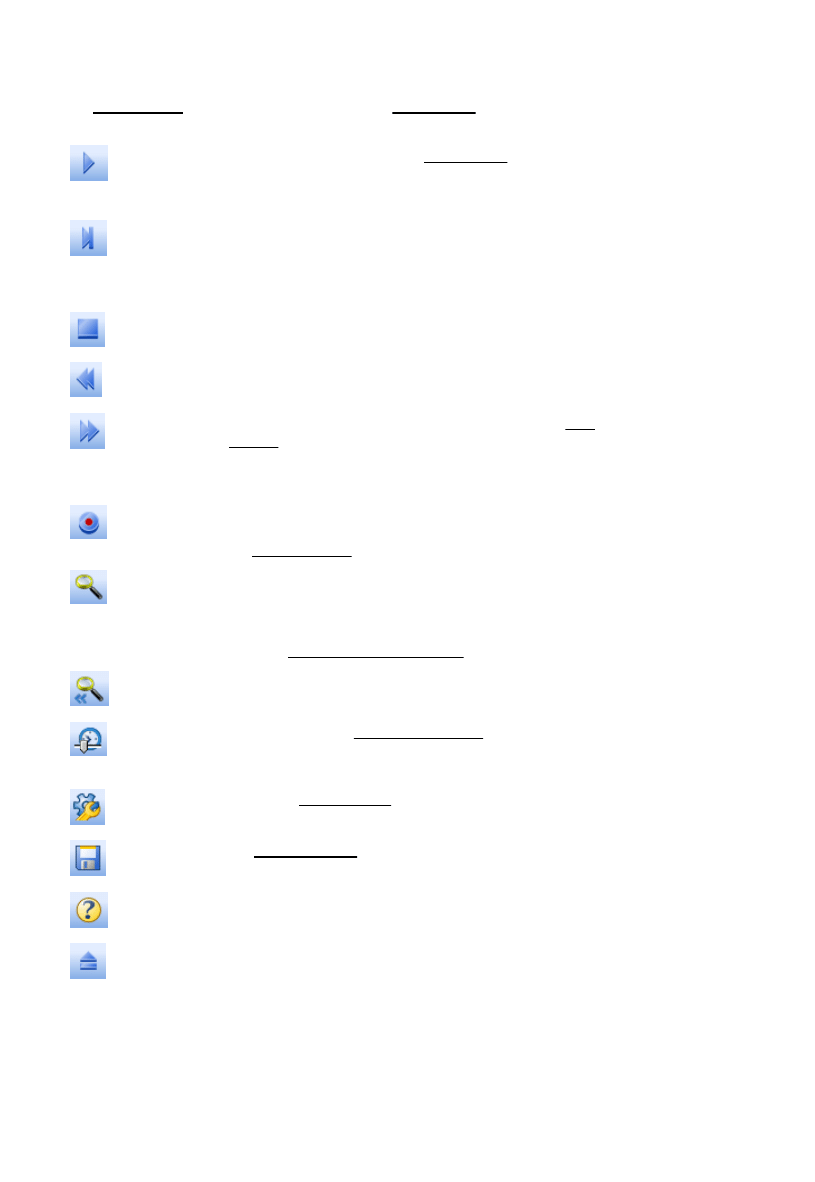
Main Toolbar
The User Interface of EdgeCAM Simulator features customisable toolbars, including the Main toolbar:
Start
Starts the simulation (see also Stop Options).
In Rapid Result the material is removed from the model and
display updated in low resolution every 100 cuts.
Play # cuts
In Machine Simulation mode, starts the simulation, playing
one cut at a time
In Rapid Result mode, starts simulation to run for specified
number of cuts (the default setting is 100)
Stop
Stops the simulation.
Rewind
Rewinds to the start of the simulation, resetting to un-
machined stock.
Fast Forward
Fast Forwards to the end of the simulation. (see also Stop
Options).
The display is only at the end of the sequence, but a
progress indicator is displayed
Click this button to activate or de-activate it. While active,
any movement in the Graphics Area is recorded to an AVI;
see Recording AVIs.
Enhance
(Only available in Rapid Result) Zoom in on a particular
area, then select the Enhance button to improve the display
quality around this area. The stock outside the zoom area is
removed.
Also see View Comparison Accuracy.
View All Stock
(Only available in Rapid Result) Resets view to display entire
model after using the Enhance option.
Toggle Speed
Control
Shows or hides the Speed Control slider.
Options dialog
Opens the Options dialog.
Save STL
See Saving STL files.
Help
Displays this help file.
Return to
EdgeCAM
Exits EdgeCAM Simulator.
7
EdgeCAM User Guide

About the EdgeCAM Simulator
The EdgeCAM Simulator has two modes, that you start from their buttons in EdgeCAM's Main toolbar (for
example):
Use mainly with mould and die parts and
surface parts.
Gives you almost instant toolpath verification
with visual comparison between machined
stock and original model.
Not recommended for production machining
and does not support the simulation of
indexing, rotary machining, turning or
undercut machining (eg, thread milling).
Collision checking slows down Rapid
Result considerably, so you should disable it
in the toolbar (
) unless necessary.
Use mainly for milling, multiplane milling, 2
axis, 4 axis and C & Y axis turning.
Tool, tool holder and fixtures are included
in the simulation.
Gives a very realistic representation of the
process.
Speed can be controlled and the view
dynamically rotated, zoomed and panned.
For turning operations, the part can be
shown as a ¾ view enabling internal
operations to be viewed clearly.
Not recommended for surface parts with
very complex toolpaths (simulation might
be very slow).
Gives you toolpath verification with visual
comparison between machined stock and
original model.
See a comparative table of features in each mode.
Please note that EdgeCAM Simulator:
EdgeCAM Simulator aims to show you the finished part that the output CNC code will produce. When
Cutter Radius Compensation is to be applied on the machine (that is when the 'Pathcomp' setting is
not used), this must be done correctly for the finished part to match the part shown in EdgeCAM
Simulator.
EdgeCAM Simulator is available in GLview only.
EdgeCAM Simulator is not strictly time-based, so twin turret simulations may lose synchronisation.
There are steps you can take to counter this.
EdgeCAM Simulator supercedes the EdgeCAM Verify product. For further details see the Verifying
the Model topic (in the Obsolete book of the online User Guide).
You may encounter problems if you output EdgeCAM surfaces as STL then use the STL file to create
digitised stock. This is because the triangles in a collection of surfaces might not be closed, whereas
stock from solids should be.
See Also:
Sub-spindle Simulation.
Simulation of 4 Axis Turning Sequences
The simulation in EdgeCAM simulator is not time based as it does not accurately simulate the feedrates
or take any account of acceleration or deceleration of axes movement.
This is of particular relevance when simulating twin turret turning sequences as the true positional
relationship of the two turrets may not be accurate, and therefore potential collisions could be missed or
incorrectly reported.
The simulation does consider the synchronisation points and the true positional relationship of the two
turrets is therefore accurate at each synchronisation point, which should be used appropriately to avoid any
potential collisions.
8
EdgeCAM User Guide
About the EdgeCAM Simulator
The EdgeCAM Simulator has two modes, that you start from their buttons in EdgeCAM's Main toolbar (for
example):
Use mainly with mould and die parts and
surface parts.
Gives you almost instant toolpath verification
with visual comparison between machined
stock and original model.
Not recommended for production machining
and does not support the simulation of
indexing, rotary machining, turning or
undercut machining (eg, thread milling).
Collision checking slows down Rapid
Result considerably, so you should disable it
in the toolbar (
) unless necessary.
Use mainly for milling, multiplane milling, 2
axis, 4 axis and C & Y axis turning.
Tool, tool holder and fixtures are included
in the simulation.
Gives a very realistic representation of the
process.
Speed can be controlled and the view
dynamically rotated, zoomed and panned.
For turning operations, the part can be
shown as a ¾ view enabling internal
operations to be viewed clearly.
Not recommended for surface parts with
very complex toolpaths (simulation might
be very slow).
Gives you toolpath verification with visual
comparison between machined stock and
original model.
See a comparative table of features in each mode.
Please note that EdgeCAM Simulator:
EdgeCAM Simulator aims to show you the finished part that the output CNC code will produce. When
Cutter Radius Compensation is to be applied on the machine (that is when the 'Pathcomp' setting is
not used), this must be done correctly for the finished part to match the part shown in EdgeCAM
Simulator.
EdgeCAM Simulator is available in GLview only.
EdgeCAM Simulator is not strictly time-based, so twin turret simulations may lose synchronisation.
There are steps you can take to counter this.
EdgeCAM Simulator supercedes the EdgeCAM Verify product. For further details see the Verifying
the Model topic (in the Obsolete book of the online User Guide).
You may encounter problems if you output EdgeCAM surfaces as STL then use the STL file to create
digitised stock. This is because the triangles in a collection of surfaces might not be closed, whereas
stock from solids should be.
See Also:
Sub-spindle Simulation.
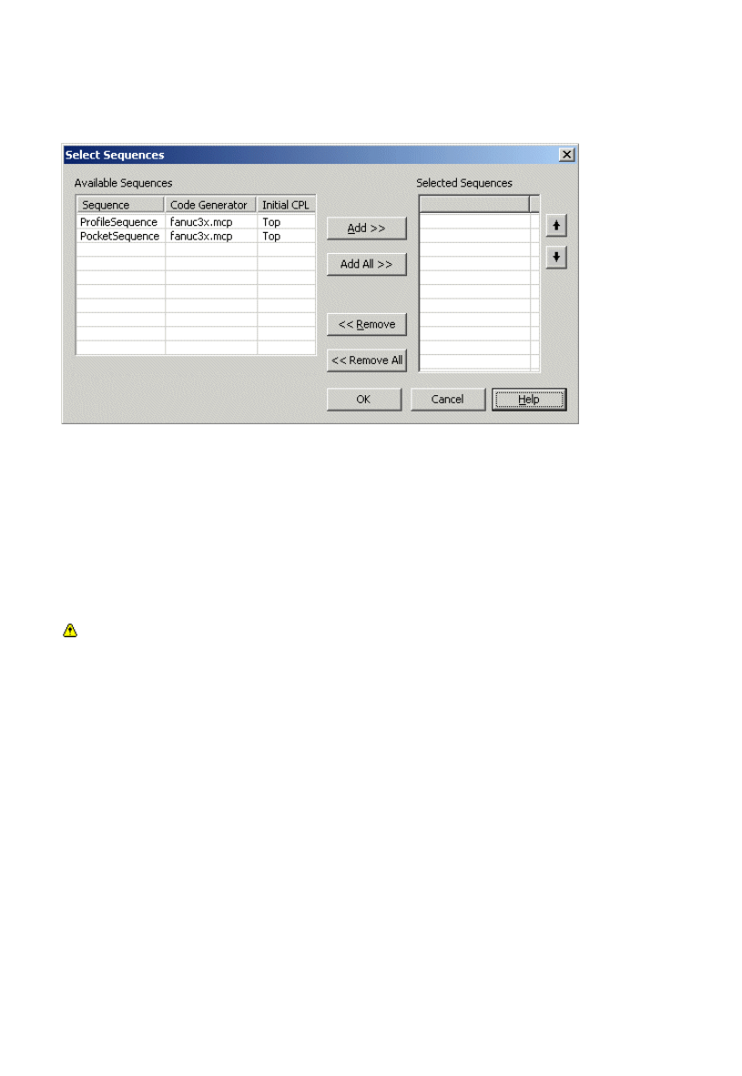
Simulating Multiple Sequences
If you activate Rapid Result or Simulate Machining when working with multiple sequences, the Select
Sequences dialog will be displayed. This allows you to select the sequence(s) you want to simulate from a
list of available sequences.
Available Sequences - A list of all available sequences that can be selected for simulation. Only
sequences which share the same discipline as the currently active sequence are displayed.
Selected Sequences - Select the sequences you want to simulate by moving them from the left to the right
panel. You can do this by simply highlighting the required sequence(s) and pressing the Add>> button. The
Add All >> button allows you to move all sequences to the right panel.
Use the Remove>> or Remove All >> button to delete sequences from the right panel and move them back
to the left panel.
To change the order in which sequences are simulated, select one or more in the right-hand panel and use
the arrows on the extreme right to change their relative positions. Sequences will be simulated in the order
shown when the command is executed.
The first sequence selected sets the code generator. Only sequences that share the same code
generator can be selected. In the case of Rapid Result both CPL and code generator have to be the same.
9
EdgeCAM User Guide

About the EdgeCAM Simulator
The EdgeCAM Simulator has two modes, that you start from their buttons in EdgeCAM's Main toolbar (for
example):
Use mainly with mould and die parts and
surface parts.
Gives you almost instant toolpath verification
with visual comparison between machined
stock and original model.
Not recommended for production machining
and does not support the simulation of
indexing, rotary machining, turning or
undercut machining (eg, thread milling).
Collision checking slows down Rapid
Result considerably, so you should disable it
in the toolbar (
) unless necessary.
Use mainly for milling, multiplane milling, 2
axis, 4 axis and C & Y axis turning.
Tool, tool holder and fixtures are included
in the simulation.
Gives a very realistic representation of the
process.
Speed can be controlled and the view
dynamically rotated, zoomed and panned.
For turning operations, the part can be
shown as a ¾ view enabling internal
operations to be viewed clearly.
Not recommended for surface parts with
very complex toolpaths (simulation might
be very slow).
Gives you toolpath verification with visual
comparison between machined stock and
original model.
See a comparative table of features in each mode.
Please note that EdgeCAM Simulator:
EdgeCAM Simulator aims to show you the finished part that the output CNC code will produce. When
Cutter Radius Compensation is to be applied on the machine (that is when the 'Pathcomp' setting is
not used), this must be done correctly for the finished part to match the part shown in EdgeCAM
Simulator.
EdgeCAM Simulator is available in GLview only.
EdgeCAM Simulator is not strictly time-based, so twin turret simulations may lose synchronisation.
There are steps you can take to counter this.
EdgeCAM Simulator supercedes the EdgeCAM Verify product. For further details see the Verifying
the Model topic (in the Obsolete book of the online User Guide).
You may encounter problems if you output EdgeCAM surfaces as STL then use the STL file to create
digitised stock. This is because the triangles in a collection of surfaces might not be closed, whereas
stock from solids should be.
See Also:
Sub-spindle Simulation.
Using Stock and Fixtures in the Simulator
The online EdgeCAM User Guide provides instructions for using stock and fixtures in EdgeCAM Simulator.
You may experience problems when outputting EdgeCAM surfaces as STL and then using the STL
file to create digitised stock. Stock created by this method may not be taken through to Simulator since
the triangles from a collection of surfaces are NOT guaranteed to be closed, whereas stock from solids
should be.
When digitising solids for stock, self-intersecting triangles and open solids are not suitable for
simulation as Boolean operations are impossible on 'corrupt solids'. A warning message will be issued
when the part is loaded into EdgeCAM Simulator. EdgeCAM Simulator will carry on simulating the part
when the warning is accepted, but will fail when it reaches the problem area.
10
EdgeCAM User Guide

About the EdgeCAM Simulator
The EdgeCAM Simulator has two modes, that you start from their buttons in EdgeCAM's Main toolbar (for
example):
Use mainly with mould and die parts and
surface parts.
Gives you almost instant toolpath verification
with visual comparison between machined
stock and original model.
Not recommended for production machining
and does not support the simulation of
indexing, rotary machining, turning or
undercut machining (eg, thread milling).
Collision checking slows down Rapid
Result considerably, so you should disable it
in the toolbar (
) unless necessary.
Use mainly for milling, multiplane milling, 2
axis, 4 axis and C & Y axis turning.
Tool, tool holder and fixtures are included
in the simulation.
Gives a very realistic representation of the
process.
Speed can be controlled and the view
dynamically rotated, zoomed and panned.
For turning operations, the part can be
shown as a ¾ view enabling internal
operations to be viewed clearly.
Not recommended for surface parts with
very complex toolpaths (simulation might
be very slow).
Gives you toolpath verification with visual
comparison between machined stock and
original model.
See a comparative table of features in each mode.
Please note that EdgeCAM Simulator:
EdgeCAM Simulator aims to show you the finished part that the output CNC code will produce. When
Cutter Radius Compensation is to be applied on the machine (that is when the 'Pathcomp' setting is
not used), this must be done correctly for the finished part to match the part shown in EdgeCAM
Simulator.
EdgeCAM Simulator is available in GLview only.
EdgeCAM Simulator is not strictly time-based, so twin turret simulations may lose synchronisation.
There are steps you can take to counter this.
EdgeCAM Simulator supercedes the EdgeCAM Verify product. For further details see the Verifying
the Model topic (in the Obsolete book of the online User Guide).
You may encounter problems if you output EdgeCAM surfaces as STL then use the STL file to create
digitised stock. This is because the triangles in a collection of surfaces might not be closed, whereas
stock from solids should be.
See Also:
Sub-spindle Simulation.
Stop Options
To specify where you want the simulation to stop:
In the Simulator toolbar click
and select one of:
1.
Stop at End - Stops simulation at the end of the sequence.
Stop at Collision - Stops simulation at the next collision.
Stop at Toolchange - Stops simulation at the next toolchange.
Stop at Index Move - Stops simulation at the next index move.
Stop at Turret Change - Stops simulation at the next turret change. Also, with twin turret turning, at
the Synchronise Turrets instructions.
Stop at Fixture Change - Stops simulation at the next fixture change.
Stop at Cut # - Stops simulation after the specified cut number.
Stop after # Cuts - Stops simulation after specified number of cuts.
If you selected one of the '#' options in a drop down list, enter the number into the dialog that opens.
(A drop down list appears if you click the ' ' part of the button, whilst a dialog opens if you click the
main part of the button. The list and the dialog contain the same options.)
2.
Note that once the simulation stops, an indication of why it stopped
appears in the bottom left of the simulator; if you had set a 'Stop at
Cut #', for example.
11
EdgeCAM User Guide

About the EdgeCAM Simulator
The EdgeCAM Simulator has two modes, that you start from their buttons in EdgeCAM's Main toolbar (for
example):
Use mainly with mould and die parts and
surface parts.
Gives you almost instant toolpath verification
with visual comparison between machined
stock and original model.
Not recommended for production machining
and does not support the simulation of
indexing, rotary machining, turning or
undercut machining (eg, thread milling).
Collision checking slows down Rapid
Result considerably, so you should disable it
in the toolbar (
) unless necessary.
Use mainly for milling, multiplane milling, 2
axis, 4 axis and C & Y axis turning.
Tool, tool holder and fixtures are included
in the simulation.
Gives a very realistic representation of the
process.
Speed can be controlled and the view
dynamically rotated, zoomed and panned.
For turning operations, the part can be
shown as a ¾ view enabling internal
operations to be viewed clearly.
Not recommended for surface parts with
very complex toolpaths (simulation might
be very slow).
Gives you toolpath verification with visual
comparison between machined stock and
original model.
See a comparative table of features in each mode.
Please note that EdgeCAM Simulator:
EdgeCAM Simulator aims to show you the finished part that the output CNC code will produce. When
Cutter Radius Compensation is to be applied on the machine (that is when the 'Pathcomp' setting is
not used), this must be done correctly for the finished part to match the part shown in EdgeCAM
Simulator.
EdgeCAM Simulator is available in GLview only.
EdgeCAM Simulator is not strictly time-based, so twin turret simulations may lose synchronisation.
There are steps you can take to counter this.
EdgeCAM Simulator supercedes the EdgeCAM Verify product. For further details see the Verifying
the Model topic (in the Obsolete book of the online User Guide).
You may encounter problems if you output EdgeCAM surfaces as STL then use the STL file to create
digitised stock. This is because the triangles in a collection of surfaces might not be closed, whereas
stock from solids should be.
See Also:
Sub-spindle Simulation.
The Graphics Area
Zooming and Rotating
You can use the same methods for zooming, rotating and panning as in EdgeCAM, as detailed in the online
User Guide.
However there are these exceptions:
Holding down the Ctrl key while you click and drag with the right-hand mouse button performs a
zoom (an alternative to the normal mouse-wheel method).
Holding down the Shift key while you click and drag with the right-hand mouse button performs a pan
(an alternative to the normal clicking and dragging with the mouse wheel ).
Display Options
To set display options:
Right-click in the Graphics Area.
1.
In the shortcut menu that opens click Options.
2.
Edit the settings in the General Options dialog.
3.
12
EdgeCAM User Guide

About the EdgeCAM Simulator
The EdgeCAM Simulator has two modes, that you start from their buttons in EdgeCAM's Main toolbar (for
example):
Use mainly with mould and die parts and
surface parts.
Gives you almost instant toolpath verification
with visual comparison between machined
stock and original model.
Not recommended for production machining
and does not support the simulation of
indexing, rotary machining, turning or
undercut machining (eg, thread milling).
Collision checking slows down Rapid
Result considerably, so you should disable it
in the toolbar (
) unless necessary.
Use mainly for milling, multiplane milling, 2
axis, 4 axis and C & Y axis turning.
Tool, tool holder and fixtures are included
in the simulation.
Gives a very realistic representation of the
process.
Speed can be controlled and the view
dynamically rotated, zoomed and panned.
For turning operations, the part can be
shown as a ¾ view enabling internal
operations to be viewed clearly.
Not recommended for surface parts with
very complex toolpaths (simulation might
be very slow).
Gives you toolpath verification with visual
comparison between machined stock and
original model.
See a comparative table of features in each mode.
Please note that EdgeCAM Simulator:
EdgeCAM Simulator aims to show you the finished part that the output CNC code will produce. When
Cutter Radius Compensation is to be applied on the machine (that is when the 'Pathcomp' setting is
not used), this must be done correctly for the finished part to match the part shown in EdgeCAM
Simulator.
EdgeCAM Simulator is available in GLview only.
EdgeCAM Simulator is not strictly time-based, so twin turret simulations may lose synchronisation.
There are steps you can take to counter this.
EdgeCAM Simulator supercedes the EdgeCAM Verify product. For further details see the Verifying
the Model topic (in the Obsolete book of the online User Guide).
You may encounter problems if you output EdgeCAM surfaces as STL then use the STL file to create
digitised stock. This is because the triangles in a collection of surfaces might not be closed, whereas
stock from solids should be.
See Also:
Sub-spindle Simulation.
Changing the View
A mouse click while the cursor is over the view caption at the bottom of the graphics screen will activate this
menu:
Select the required option and the model will be displayed in the new view.
13
EdgeCAM User Guide

About the EdgeCAM Simulator
The EdgeCAM Simulator has two modes, that you start from their buttons in EdgeCAM's Main toolbar (for
example):
Use mainly with mould and die parts and
surface parts.
Gives you almost instant toolpath verification
with visual comparison between machined
stock and original model.
Not recommended for production machining
and does not support the simulation of
indexing, rotary machining, turning or
undercut machining (eg, thread milling).
Collision checking slows down Rapid
Result considerably, so you should disable it
in the toolbar (
) unless necessary.
Use mainly for milling, multiplane milling, 2
axis, 4 axis and C & Y axis turning.
Tool, tool holder and fixtures are included
in the simulation.
Gives a very realistic representation of the
process.
Speed can be controlled and the view
dynamically rotated, zoomed and panned.
For turning operations, the part can be
shown as a ¾ view enabling internal
operations to be viewed clearly.
Not recommended for surface parts with
very complex toolpaths (simulation might
be very slow).
Gives you toolpath verification with visual
comparison between machined stock and
original model.
See a comparative table of features in each mode.
Please note that EdgeCAM Simulator:
EdgeCAM Simulator aims to show you the finished part that the output CNC code will produce. When
Cutter Radius Compensation is to be applied on the machine (that is when the 'Pathcomp' setting is
not used), this must be done correctly for the finished part to match the part shown in EdgeCAM
Simulator.
EdgeCAM Simulator is available in GLview only.
EdgeCAM Simulator is not strictly time-based, so twin turret simulations may lose synchronisation.
There are steps you can take to counter this.
EdgeCAM Simulator supercedes the EdgeCAM Verify product. For further details see the Verifying
the Model topic (in the Obsolete book of the online User Guide).
You may encounter problems if you output EdgeCAM surfaces as STL then use the STL file to create
digitised stock. This is because the triangles in a collection of surfaces might not be closed, whereas
stock from solids should be.
See Also:
Sub-spindle Simulation.
Speed Control
To change the simulation speed from its default..., display the Speed Control by clicking its
button the Main toolbar. (Alternatively right-click in the Graphics Area and in the shortcut menu
that opens click View Speed Control .)
Move the Speed Control slider left to slow down or right to speed up.
The simulation proceeds at a fixed frame rate; the slider sets how far the tool moves between frames.
To set the speed range click the Speed Options button and in the dialog that opens set the
following options:
Simulator
Minimum Step per Frame
The linear distance travelled by the tool between frames with the slider on
minimum.
Maximum Step per Frame
The linear distance travelled by the tool between frames with the slider on
maximum.
Minimum Angular Step per
Frame
The angular distance travelled by the tool between frames with the slider
on minimum.
Maximum Angular Step per
Frame
The angular distance travelled by the tool between frames with the slider
on maximum.
Rapid Result
Minimum Cuts per Frame
The number of cuts between frames with the slider on minimum.
Minimum/Maximum Cuts
per Frame
The number of cuts between frames with the slider on maximum.
Fast Render
Check this box to enable fast rendering with an approximated display of the
toolpath. Unchecking the option provides a better quality of display during
the simulation.
14
EdgeCAM User Guide

About the EdgeCAM Simulator
The EdgeCAM Simulator has two modes, that you start from their buttons in EdgeCAM's Main toolbar (for
example):
Use mainly with mould and die parts and
surface parts.
Gives you almost instant toolpath verification
with visual comparison between machined
stock and original model.
Not recommended for production machining
and does not support the simulation of
indexing, rotary machining, turning or
undercut machining (eg, thread milling).
Collision checking slows down Rapid
Result considerably, so you should disable it
in the toolbar (
) unless necessary.
Use mainly for milling, multiplane milling, 2
axis, 4 axis and C & Y axis turning.
Tool, tool holder and fixtures are included
in the simulation.
Gives a very realistic representation of the
process.
Speed can be controlled and the view
dynamically rotated, zoomed and panned.
For turning operations, the part can be
shown as a ¾ view enabling internal
operations to be viewed clearly.
Not recommended for surface parts with
very complex toolpaths (simulation might
be very slow).
Gives you toolpath verification with visual
comparison between machined stock and
original model.
See a comparative table of features in each mode.
Please note that EdgeCAM Simulator:
EdgeCAM Simulator aims to show you the finished part that the output CNC code will produce. When
Cutter Radius Compensation is to be applied on the machine (that is when the 'Pathcomp' setting is
not used), this must be done correctly for the finished part to match the part shown in EdgeCAM
Simulator.
EdgeCAM Simulator is available in GLview only.
EdgeCAM Simulator is not strictly time-based, so twin turret simulations may lose synchronisation.
There are steps you can take to counter this.
EdgeCAM Simulator supercedes the EdgeCAM Verify product. For further details see the Verifying
the Model topic (in the Obsolete book of the online User Guide).
You may encounter problems if you output EdgeCAM surfaces as STL then use the STL file to create
digitised stock. This is because the triangles in a collection of surfaces might not be closed, whereas
stock from solids should be.
See Also:
Sub-spindle Simulation.
Tool Holder Collision Checking
In Simulate Machining, selecting the Collision Check Tool Holder
command will switch on the tool
holder display and the collision checking functionality.
In Rapid Result, selecting the Collision Check Tool Holder
command will switch on the collision
checking functionality only. The tool holder graphics will not be displayed.
Please note that Rapid Result does not check for tool holder collisions if the tool cutting depth is greater
than the flute length.
15
EdgeCAM User Guide
About the EdgeCAM Simulator
The EdgeCAM Simulator has two modes, that you start from their buttons in EdgeCAM's Main toolbar (for
example):
Use mainly with mould and die parts and
surface parts.
Gives you almost instant toolpath verification
with visual comparison between machined
stock and original model.
Not recommended for production machining
and does not support the simulation of
indexing, rotary machining, turning or
undercut machining (eg, thread milling).
Collision checking slows down Rapid
Result considerably, so you should disable it
in the toolbar (
) unless necessary.
Use mainly for milling, multiplane milling, 2
axis, 4 axis and C & Y axis turning.
Tool, tool holder and fixtures are included
in the simulation.
Gives a very realistic representation of the
process.
Speed can be controlled and the view
dynamically rotated, zoomed and panned.
For turning operations, the part can be
shown as a ¾ view enabling internal
operations to be viewed clearly.
Not recommended for surface parts with
very complex toolpaths (simulation might
be very slow).
Gives you toolpath verification with visual
comparison between machined stock and
original model.
See a comparative table of features in each mode.
Please note that EdgeCAM Simulator:
EdgeCAM Simulator aims to show you the finished part that the output CNC code will produce. When
Cutter Radius Compensation is to be applied on the machine (that is when the 'Pathcomp' setting is
not used), this must be done correctly for the finished part to match the part shown in EdgeCAM
Simulator.
EdgeCAM Simulator is available in GLview only.
EdgeCAM Simulator is not strictly time-based, so twin turret simulations may lose synchronisation.
There are steps you can take to counter this.
EdgeCAM Simulator supercedes the EdgeCAM Verify product. For further details see the Verifying
the Model topic (in the Obsolete book of the online User Guide).
You may encounter problems if you output EdgeCAM surfaces as STL then use the STL file to create
digitised stock. This is because the triangles in a collection of surfaces might not be closed, whereas
stock from solids should be.
See Also:
Sub-spindle Simulation.
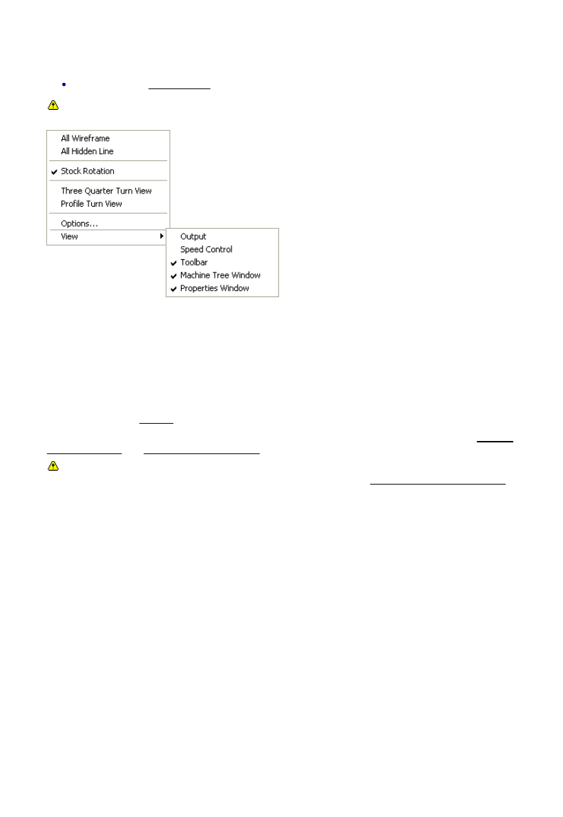
The Simulator Shortcut Menu
Right-click in the Graphics area to open a shortcut menu.
In Rapid Result only the View menu items are available.
All Wireframe - Check to display all elements on the graphics screen in wireframe.
All Hidden Line - Check to display all elements on the graphics screen in wireframe with hidden lines
removed.
Stock Rotation - Check this option for the stock to move as it would in reality; as rotated by a chuck, or a
rotating table for example. Uncheck this for the stock to be stationary, with the relative movement displayed
only by the tool.
In turning, you can choose between a Three Quarter Turn View and a Profile Turn View.
Options - opens the Options dialog.
View Output/Speed Control...etc - Items for showing or hiding each toolbar and window. See Working
with the Toolbars and Working with the Windows.
To select the display options for the stock, the part model, the tool, the tool holder and the fixtures use
the drop-down menu on the appropriate icon in the Simulator toolbar (see Controlling the Display Options).
16
EdgeCAM User Guide
About the EdgeCAM Simulator
The EdgeCAM Simulator has two modes, that you start from their buttons in EdgeCAM's Main toolbar (for
example):
Use mainly with mould and die parts and
surface parts.
Gives you almost instant toolpath verification
with visual comparison between machined
stock and original model.
Not recommended for production machining
and does not support the simulation of
indexing, rotary machining, turning or
undercut machining (eg, thread milling).
Collision checking slows down Rapid
Result considerably, so you should disable it
in the toolbar (
) unless necessary.
Use mainly for milling, multiplane milling, 2
axis, 4 axis and C & Y axis turning.
Tool, tool holder and fixtures are included
in the simulation.
Gives a very realistic representation of the
process.
Speed can be controlled and the view
dynamically rotated, zoomed and panned.
For turning operations, the part can be
shown as a ¾ view enabling internal
operations to be viewed clearly.
Not recommended for surface parts with
very complex toolpaths (simulation might
be very slow).
Gives you toolpath verification with visual
comparison between machined stock and
original model.
See a comparative table of features in each mode.
Please note that EdgeCAM Simulator:
EdgeCAM Simulator aims to show you the finished part that the output CNC code will produce. When
Cutter Radius Compensation is to be applied on the machine (that is when the 'Pathcomp' setting is
not used), this must be done correctly for the finished part to match the part shown in EdgeCAM
Simulator.
EdgeCAM Simulator is available in GLview only.
EdgeCAM Simulator is not strictly time-based, so twin turret simulations may lose synchronisation.
There are steps you can take to counter this.
EdgeCAM Simulator supercedes the EdgeCAM Verify product. For further details see the Verifying
the Model topic (in the Obsolete book of the online User Guide).
You may encounter problems if you output EdgeCAM surfaces as STL then use the STL file to create
digitised stock. This is because the triangles in a collection of surfaces might not be closed, whereas
stock from solids should be.
See Also:
Sub-spindle Simulation.
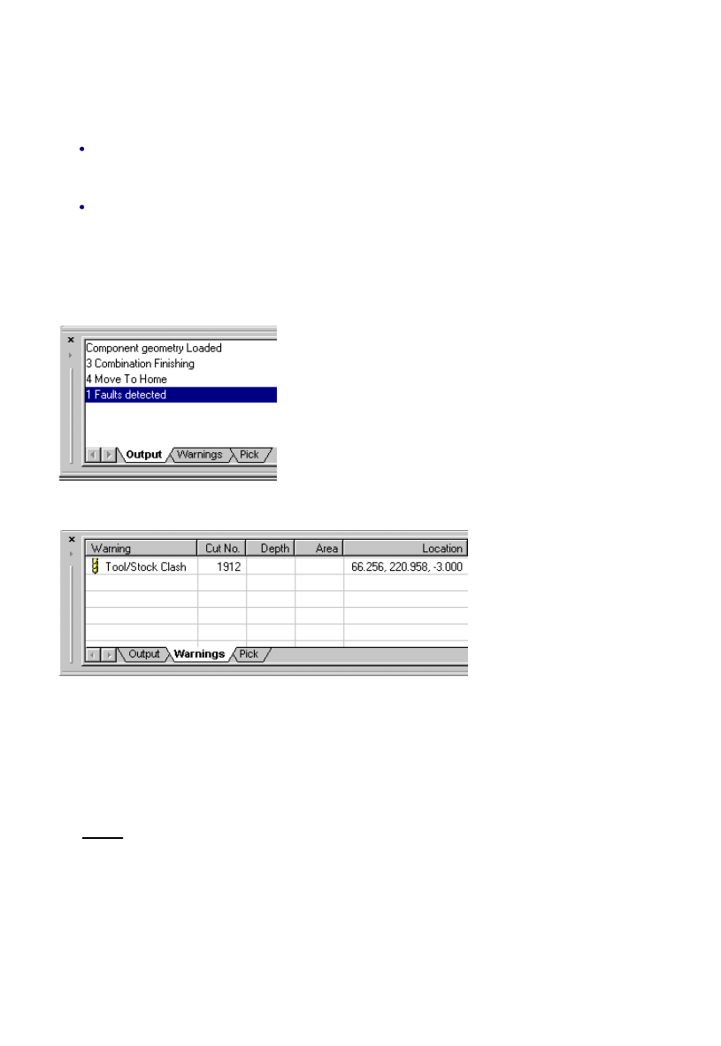
Output Window
At the bottom of the Simulator is the Output window, that provides feedback on the simulation.
To clear the Output window:
Right-click in the Output Window and in the shortcut menu that opens click Clear.
To show or hide the Output window:
Right-click in the Graphics area of the Simulator in the shortcut menu that opens click View
Output.
The Output window features the following tabs.
Output tab
This shows general feedback on the simulation:
Warnings tab
This shows details of the detected faults:
Tool/Stock Clash - either the tool rapids into the stock or the tool holder collides with the stock.
Gouge - the tool has cut too deeply.
Undersized Stock - the target geometry 'sticks out' from the stock.
Double-clicking on a warning will pinpoint the location of the fault on the graphics screen.
Pick tab
See Picking.
17
EdgeCAM User Guide
About the EdgeCAM Simulator
The EdgeCAM Simulator has two modes, that you start from their buttons in EdgeCAM's Main toolbar (for
example):
Use mainly with mould and die parts and
surface parts.
Gives you almost instant toolpath verification
with visual comparison between machined
stock and original model.
Not recommended for production machining
and does not support the simulation of
indexing, rotary machining, turning or
undercut machining (eg, thread milling).
Collision checking slows down Rapid
Result considerably, so you should disable it
in the toolbar (
) unless necessary.
Use mainly for milling, multiplane milling, 2
axis, 4 axis and C & Y axis turning.
Tool, tool holder and fixtures are included
in the simulation.
Gives a very realistic representation of the
process.
Speed can be controlled and the view
dynamically rotated, zoomed and panned.
For turning operations, the part can be
shown as a ¾ view enabling internal
operations to be viewed clearly.
Not recommended for surface parts with
very complex toolpaths (simulation might
be very slow).
Gives you toolpath verification with visual
comparison between machined stock and
original model.
See a comparative table of features in each mode.
Please note that EdgeCAM Simulator:
EdgeCAM Simulator aims to show you the finished part that the output CNC code will produce. When
Cutter Radius Compensation is to be applied on the machine (that is when the 'Pathcomp' setting is
not used), this must be done correctly for the finished part to match the part shown in EdgeCAM
Simulator.
EdgeCAM Simulator is available in GLview only.
EdgeCAM Simulator is not strictly time-based, so twin turret simulations may lose synchronisation.
There are steps you can take to counter this.
EdgeCAM Simulator supercedes the EdgeCAM Verify product. For further details see the Verifying
the Model topic (in the Obsolete book of the online User Guide).
You may encounter problems if you output EdgeCAM surfaces as STL then use the STL file to create
digitised stock. This is because the triangles in a collection of surfaces might not be closed, whereas
stock from solids should be.
See Also:
Sub-spindle Simulation.
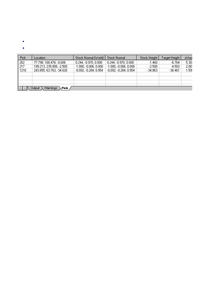
Picking
To display detailed information about a specific point on the model pick the appropriate spot on the model
with a left-hand mouse click. The information will be displayed on the Pick tab of the report window.
The information is limited to Pick (cut number) and Location in Simulate Machining mode.
To clear the information, right-click in the window and from the shortcut menu select Clear.
Pick - Identifies the cut number during the simulation.
Location - The co-ordinates of the point picked on the model.
World Stock Normal - The axis in which the measurement was performed.
Stock Normal - The axis in which the measurement was performed.
Stock Height - The height of the stock at the point selected.
Target Height - The height of the target at the point selected.
d Axial - The axial distance from the process stock to the component surface.
d Normal - The shortest distance from the picked point to the target part surface
18
EdgeCAM User Guide

About the EdgeCAM Simulator
The EdgeCAM Simulator has two modes, that you start from their buttons in EdgeCAM's Main toolbar (for
example):
Use mainly with mould and die parts and
surface parts.
Gives you almost instant toolpath verification
with visual comparison between machined
stock and original model.
Not recommended for production machining
and does not support the simulation of
indexing, rotary machining, turning or
undercut machining (eg, thread milling).
Collision checking slows down Rapid
Result considerably, so you should disable it
in the toolbar (
) unless necessary.
Use mainly for milling, multiplane milling, 2
axis, 4 axis and C & Y axis turning.
Tool, tool holder and fixtures are included
in the simulation.
Gives a very realistic representation of the
process.
Speed can be controlled and the view
dynamically rotated, zoomed and panned.
For turning operations, the part can be
shown as a ¾ view enabling internal
operations to be viewed clearly.
Not recommended for surface parts with
very complex toolpaths (simulation might
be very slow).
Gives you toolpath verification with visual
comparison between machined stock and
original model.
See a comparative table of features in each mode.
Please note that EdgeCAM Simulator:
EdgeCAM Simulator aims to show you the finished part that the output CNC code will produce. When
Cutter Radius Compensation is to be applied on the machine (that is when the 'Pathcomp' setting is
not used), this must be done correctly for the finished part to match the part shown in EdgeCAM
Simulator.
EdgeCAM Simulator is available in GLview only.
EdgeCAM Simulator is not strictly time-based, so twin turret simulations may lose synchronisation.
There are steps you can take to counter this.
EdgeCAM Simulator supercedes the EdgeCAM Verify product. For further details see the Verifying
the Model topic (in the Obsolete book of the online User Guide).
You may encounter problems if you output EdgeCAM surfaces as STL then use the STL file to create
digitised stock. This is because the triangles in a collection of surfaces might not be closed, whereas
stock from solids should be.
See Also:
Sub-spindle Simulation.
Saving Stock as STL Files
The Save STL
button on the Simulator toolbar allows you to create STL files from stock. These can
then be reloaded into EdgeCAM and used for further machining sessions.
It is possible to save multiple STL files during a single simulation session.
The ability to import STL files requires a licence that includes access to Surface Design.
19
EdgeCAM User Guide

About the EdgeCAM Simulator
The EdgeCAM Simulator has two modes, that you start from their buttons in EdgeCAM's Main toolbar (for
example):
Use mainly with mould and die parts and
surface parts.
Gives you almost instant toolpath verification
with visual comparison between machined
stock and original model.
Not recommended for production machining
and does not support the simulation of
indexing, rotary machining, turning or
undercut machining (eg, thread milling).
Collision checking slows down Rapid
Result considerably, so you should disable it
in the toolbar (
) unless necessary.
Use mainly for milling, multiplane milling, 2
axis, 4 axis and C & Y axis turning.
Tool, tool holder and fixtures are included
in the simulation.
Gives a very realistic representation of the
process.
Speed can be controlled and the view
dynamically rotated, zoomed and panned.
For turning operations, the part can be
shown as a ¾ view enabling internal
operations to be viewed clearly.
Not recommended for surface parts with
very complex toolpaths (simulation might
be very slow).
Gives you toolpath verification with visual
comparison between machined stock and
original model.
See a comparative table of features in each mode.
Please note that EdgeCAM Simulator:
EdgeCAM Simulator aims to show you the finished part that the output CNC code will produce. When
Cutter Radius Compensation is to be applied on the machine (that is when the 'Pathcomp' setting is
not used), this must be done correctly for the finished part to match the part shown in EdgeCAM
Simulator.
EdgeCAM Simulator is available in GLview only.
EdgeCAM Simulator is not strictly time-based, so twin turret simulations may lose synchronisation.
There are steps you can take to counter this.
EdgeCAM Simulator supercedes the EdgeCAM Verify product. For further details see the Verifying
the Model topic (in the Obsolete book of the online User Guide).
You may encounter problems if you output EdgeCAM surfaces as STL then use the STL file to create
digitised stock. This is because the triangles in a collection of surfaces might not be closed, whereas
stock from solids should be.
See Also:
Sub-spindle Simulation.
Returning to EdgeCAM
To close the Simulator and return to EdgeCAM, click on the Return to EdgeCAM
icon at the right-hand
side of the toolbar.
20
EdgeCAM User Guide

About the EdgeCAM Simulator
The EdgeCAM Simulator has two modes, that you start from their buttons in EdgeCAM's Main toolbar (for
example):
Use mainly with mould and die parts and
surface parts.
Gives you almost instant toolpath verification
with visual comparison between machined
stock and original model.
Not recommended for production machining
and does not support the simulation of
indexing, rotary machining, turning or
undercut machining (eg, thread milling).
Collision checking slows down Rapid
Result considerably, so you should disable it
in the toolbar (
) unless necessary.
Use mainly for milling, multiplane milling, 2
axis, 4 axis and C & Y axis turning.
Tool, tool holder and fixtures are included
in the simulation.
Gives a very realistic representation of the
process.
Speed can be controlled and the view
dynamically rotated, zoomed and panned.
For turning operations, the part can be
shown as a ¾ view enabling internal
operations to be viewed clearly.
Not recommended for surface parts with
very complex toolpaths (simulation might
be very slow).
Gives you toolpath verification with visual
comparison between machined stock and
original model.
See a comparative table of features in each mode.
Please note that EdgeCAM Simulator:
EdgeCAM Simulator aims to show you the finished part that the output CNC code will produce. When
Cutter Radius Compensation is to be applied on the machine (that is when the 'Pathcomp' setting is
not used), this must be done correctly for the finished part to match the part shown in EdgeCAM
Simulator.
EdgeCAM Simulator is available in GLview only.
EdgeCAM Simulator is not strictly time-based, so twin turret simulations may lose synchronisation.
There are steps you can take to counter this.
EdgeCAM Simulator supercedes the EdgeCAM Verify product. For further details see the Verifying
the Model topic (in the Obsolete book of the online User Guide).
You may encounter problems if you output EdgeCAM surfaces as STL then use the STL file to create
digitised stock. This is because the triangles in a collection of surfaces might not be closed, whereas
stock from solids should be.
See Also:
Sub-spindle Simulation.
Recording AVIs
You can record movement in the Graphics Area, such as a simulation run, to an AVI. To do this:
Right-click in the Graphics Area, from the shortcut menu select Options and switch to the Animation
tab. Set the required Output Folder (where the recorded .AVI file will be saved), and Frame Rate
(the default of 30 is typical).
1.
Optionally, hide the CPL marker for a cleaner AVI. Do this by following Step 1, but uncheck the Show
CPL option in the Display tab. Implement the new setting by clicking Rewind.
2.
Size the Simulator window so the Graphics Area is the size you want it to appear in the recording.
3.
In the Main Toolbar click the
button to activate it.
4.
Complete the Video Compression dialog that opens:
Select a codec from the Compressor list.
Optionally, click the Configure button and make codec settings (not available for all codecs).
Click OK to confirm and close the dialog.
5.
Any movement is now recorded - whether you start the simulation run, or zoom or pan the part. When
there is no movement (if you pause the simulation or stop panning), the recording is also effectively
paused.
6.
To stop the recording click the
button again to de-activate it.
7.
The recording is saved to an AVI in the following format:
Output Folder\partName_DDMMYY_HH_MM.avi
where 'DDMMYY_HH_MM' is the Day, Month, Year, Hour and Minute that the recording started.
And 'Output Folder' was set in Step 1 above.
For example:
C:\EdgeCAM Work\Animations\flange_190406_10_07.avi
8.
21
EdgeCAM User Guide

About the EdgeCAM Simulator
The EdgeCAM Simulator has two modes, that you start from their buttons in EdgeCAM's Main toolbar (for
example):
Use mainly with mould and die parts and
surface parts.
Gives you almost instant toolpath verification
with visual comparison between machined
stock and original model.
Not recommended for production machining
and does not support the simulation of
indexing, rotary machining, turning or
undercut machining (eg, thread milling).
Collision checking slows down Rapid
Result considerably, so you should disable it
in the toolbar (
) unless necessary.
Use mainly for milling, multiplane milling, 2
axis, 4 axis and C & Y axis turning.
Tool, tool holder and fixtures are included
in the simulation.
Gives a very realistic representation of the
process.
Speed can be controlled and the view
dynamically rotated, zoomed and panned.
For turning operations, the part can be
shown as a ¾ view enabling internal
operations to be viewed clearly.
Not recommended for surface parts with
very complex toolpaths (simulation might
be very slow).
Gives you toolpath verification with visual
comparison between machined stock and
original model.
See a comparative table of features in each mode.
Please note that EdgeCAM Simulator:
EdgeCAM Simulator aims to show you the finished part that the output CNC code will produce. When
Cutter Radius Compensation is to be applied on the machine (that is when the 'Pathcomp' setting is
not used), this must be done correctly for the finished part to match the part shown in EdgeCAM
Simulator.
EdgeCAM Simulator is available in GLview only.
EdgeCAM Simulator is not strictly time-based, so twin turret simulations may lose synchronisation.
There are steps you can take to counter this.
EdgeCAM Simulator supercedes the EdgeCAM Verify product. For further details see the Verifying
the Model topic (in the Obsolete book of the online User Guide).
You may encounter problems if you output EdgeCAM surfaces as STL then use the STL file to create
digitised stock. This is because the triangles in a collection of surfaces might not be closed, whereas
stock from solids should be.
See Also:
Sub-spindle Simulation.
22
EdgeCAM User Guide

About the EdgeCAM Simulator
The EdgeCAM Simulator has two modes, that you start from their buttons in EdgeCAM's Main toolbar (for
example):
Use mainly with mould and die parts and
surface parts.
Gives you almost instant toolpath verification
with visual comparison between machined
stock and original model.
Not recommended for production machining
and does not support the simulation of
indexing, rotary machining, turning or
undercut machining (eg, thread milling).
Collision checking slows down Rapid
Result considerably, so you should disable it
in the toolbar (
) unless necessary.
Use mainly for milling, multiplane milling, 2
axis, 4 axis and C & Y axis turning.
Tool, tool holder and fixtures are included
in the simulation.
Gives a very realistic representation of the
process.
Speed can be controlled and the view
dynamically rotated, zoomed and panned.
For turning operations, the part can be
shown as a ¾ view enabling internal
operations to be viewed clearly.
Not recommended for surface parts with
very complex toolpaths (simulation might
be very slow).
Gives you toolpath verification with visual
comparison between machined stock and
original model.
See a comparative table of features in each mode.
Please note that EdgeCAM Simulator:
EdgeCAM Simulator aims to show you the finished part that the output CNC code will produce. When
Cutter Radius Compensation is to be applied on the machine (that is when the 'Pathcomp' setting is
not used), this must be done correctly for the finished part to match the part shown in EdgeCAM
Simulator.
EdgeCAM Simulator is available in GLview only.
EdgeCAM Simulator is not strictly time-based, so twin turret simulations may lose synchronisation.
There are steps you can take to counter this.
EdgeCAM Simulator supercedes the EdgeCAM Verify product. For further details see the Verifying
the Model topic (in the Obsolete book of the online User Guide).
You may encounter problems if you output EdgeCAM surfaces as STL then use the STL file to create
digitised stock. This is because the triangles in a collection of surfaces might not be closed, whereas
stock from solids should be.
See Also:
Sub-spindle Simulation.
23
EdgeCAM User Guide
About the EdgeCAM Simulator
The EdgeCAM Simulator has two modes, that you start from their buttons in EdgeCAM's Main toolbar (for
example):
Use mainly with mould and die parts and
surface parts.
Gives you almost instant toolpath verification
with visual comparison between machined
stock and original model.
Not recommended for production machining
and does not support the simulation of
indexing, rotary machining, turning or
undercut machining (eg, thread milling).
Collision checking slows down Rapid
Result considerably, so you should disable it
in the toolbar (
) unless necessary.
Use mainly for milling, multiplane milling, 2
axis, 4 axis and C & Y axis turning.
Tool, tool holder and fixtures are included
in the simulation.
Gives a very realistic representation of the
process.
Speed can be controlled and the view
dynamically rotated, zoomed and panned.
For turning operations, the part can be
shown as a ¾ view enabling internal
operations to be viewed clearly.
Not recommended for surface parts with
very complex toolpaths (simulation might
be very slow).
Gives you toolpath verification with visual
comparison between machined stock and
original model.
See a comparative table of features in each mode.
Please note that EdgeCAM Simulator:
EdgeCAM Simulator aims to show you the finished part that the output CNC code will produce. When
Cutter Radius Compensation is to be applied on the machine (that is when the 'Pathcomp' setting is
not used), this must be done correctly for the finished part to match the part shown in EdgeCAM
Simulator.
EdgeCAM Simulator is available in GLview only.
EdgeCAM Simulator is not strictly time-based, so twin turret simulations may lose synchronisation.
There are steps you can take to counter this.
EdgeCAM Simulator supercedes the EdgeCAM Verify product. For further details see the Verifying
the Model topic (in the Obsolete book of the online User Guide).
You may encounter problems if you output EdgeCAM surfaces as STL then use the STL file to create
digitised stock. This is because the triangles in a collection of surfaces might not be closed, whereas
stock from solids should be.
See Also:
Sub-spindle Simulation.
Comparing Overview
Click the View Comparison button in the Display Toolbar for a color coded comparison of the
original model against the final machined stock.
If possible, compare in Rapid Result Mode, as this is more comprehensive - see below.
Otherwise compare in Simulate Machining mode. (Rapid Result is not available for, indexing,
rotary machining, turning or undercut machining (such as thread milling) and 4/5 Axis milling.)
In Rapid Result mode:
Use Picking to display detailed information on a point on the model.
Use Comparison Offset to take any deliberate machining offsets into account.
In Simulate Machining mode:
To improve the accuracy of the comparison on prismatic type parts specify a tool faceting tolerance
option. This will reduce the colour banding effect.
Stock Remaining
Nominal Size
Gouge
Component
Machined Stock
Comparison
In Rapid Result mode, after rotating or zooming the view click the Enhance button to
regenerate the comparison (optimises the comparison sample points for the new view).
In Simulate Machining Mode, re-click the View Comparison button after zooming or rotating.
The accuracy of the comparison display may not reflect the tolerances used within the machining cycles.
24
EdgeCAM User Guide

About the EdgeCAM Simulator
The EdgeCAM Simulator has two modes, that you start from their buttons in EdgeCAM's Main toolbar (for
example):
Use mainly with mould and die parts and
surface parts.
Gives you almost instant toolpath verification
with visual comparison between machined
stock and original model.
Not recommended for production machining
and does not support the simulation of
indexing, rotary machining, turning or
undercut machining (eg, thread milling).
Collision checking slows down Rapid
Result considerably, so you should disable it
in the toolbar (
) unless necessary.
Use mainly for milling, multiplane milling, 2
axis, 4 axis and C & Y axis turning.
Tool, tool holder and fixtures are included
in the simulation.
Gives a very realistic representation of the
process.
Speed can be controlled and the view
dynamically rotated, zoomed and panned.
For turning operations, the part can be
shown as a ¾ view enabling internal
operations to be viewed clearly.
Not recommended for surface parts with
very complex toolpaths (simulation might
be very slow).
Gives you toolpath verification with visual
comparison between machined stock and
original model.
See a comparative table of features in each mode.
Please note that EdgeCAM Simulator:
EdgeCAM Simulator aims to show you the finished part that the output CNC code will produce. When
Cutter Radius Compensation is to be applied on the machine (that is when the 'Pathcomp' setting is
not used), this must be done correctly for the finished part to match the part shown in EdgeCAM
Simulator.
EdgeCAM Simulator is available in GLview only.
EdgeCAM Simulator is not strictly time-based, so twin turret simulations may lose synchronisation.
There are steps you can take to counter this.
EdgeCAM Simulator supercedes the EdgeCAM Verify product. For further details see the Verifying
the Model topic (in the Obsolete book of the online User Guide).
You may encounter problems if you output EdgeCAM surfaces as STL then use the STL file to create
digitised stock. This is because the triangles in a collection of surfaces might not be closed, whereas
stock from solids should be.
See Also:
Sub-spindle Simulation.
Comparison Offset
When comparing in Rapid Result mode, you can use a Comparison Offset option, to counter any deliberate
offsets you used in your machining.
If you know your machined part will differ from the original part model, you can use this factor to adjust the
original part model before the comparison. The factor is a three dimensional offset.
As an example if you set an negative offset of -0.2 in your finishing cycle, then specify this value as the
comparison offset, the comparison will show the component finished to size. With no comparison offset the
part would be shown to be undersize.
25
EdgeCAM User Guide
Document Outline
- EdgeCAM Simulator
Wyszukiwarka
Podobne podstrony:
EdgeCAM concepts id 150177 Nieznany
ZPTL 04 ARIS Simulation id 5927 Nieznany
Abolicja podatkowa id 50334 Nieznany (2)
4 LIDER MENEDZER id 37733 Nieznany (2)
katechezy MB id 233498 Nieznany
metro sciaga id 296943 Nieznany
perf id 354744 Nieznany
interbase id 92028 Nieznany
Mbaku id 289860 Nieznany
Probiotyki antybiotyki id 66316 Nieznany
miedziowanie cz 2 id 113259 Nieznany
LTC1729 id 273494 Nieznany
D11B7AOver0400 id 130434 Nieznany
analiza ryzyka bio id 61320 Nieznany
pedagogika ogolna id 353595 Nieznany
Misc3 id 302777 Nieznany
cw med 5 id 122239 Nieznany
więcej podobnych podstron