mikroElektronika : books : Introduction to PLC controllers
Introduction to PLC controllers
on-line
FREE
!
Index
Development systems
Contact us
Previous page
Introduction to PLC controllers
on-line
,
FREE!
author: Nebojsa Matic
PLC are industrial microcontroller systems (in more recent times we meet processors instead of
microcontrollers) where hardware and software are specifically adapted to industrial environment. The
key to their success is the fact that you don't have to learn a new programming language to program
them. How do they work exactly ? How to connect a simple sensor ? How to program in ladder
diagram ? In this book you will find answers for this question and more...
E-mail a friend about this item
Contents:
Chapter I
Chapter II
Introduction to PLC controllers
Chapter III
Connecting sensors and output devices
3.1 Sinking-Sourcing concept
3.2 Input lines
3.3 Output lines
Chapter IV
Architecture of a specific PLC controller
Chapter V
Introduction
5.1 Relay diagram
5.2 Normally open and Normally closed contacts
5.3 Short example
Chapter VI
SYSWIN, program for PLC controller
Chapter VII
Introduction
7.1 Self-maintenance
7.2 Making large time intervals
7.3 Counter over 9999
7.4 Delays of ON and OFF status
7.5 Alternate ON-OFF output
7.6 Automation of parking garage for 100 vehicles
7.7 Operating a charge and discharge process
7.8 Automation of product packaging
7.9 Automation a storage door
Appendix A
Expanding the number of I/O lines
Introduction
A.1 Differences and similarities
A.2 Marking a PLC controller
A.3 Specific case
Appendix B
Detailed memory map for PLC controller
Appendix C
Appendix D
Introduction
D.1 Decimal numerical system
D.2 Binary numerical system
http://www.mikroelektronika.co.yu/english/product/books/PLCbook/plcbook.htm (1 sur 2)05/11/2004 02:37:08
mikroElektronika : books : Introduction to PLC controllers
D.3 Hexadecimal numerical system
Appendix E
Download:
mikroElektronika recommends:
PIC PLC
System with 16 inputs and
16 outputs.
PIC PLC is a system for installing into
devices as well as for developing
industrial control. With 16 relays and
16 optocoupled inputs, power supply
and a box, it makes very flexible
system. [
]
On-line book
Components of electronic devices
This book is meant for the people with desire
to create electronic devices with their own
hands. All the examples are illustrated and
each component in the scheme is explained in
details. Beside the complex examples that can
have practical application, there are also
elementary examples to guarantee successful
]
To readers knowledge:
The contents published in the book "Introduction to PLC controllers" is subject to copyright and it must not be reproduced in any
form without an explicit written permission released from the editorial of mikroElektronika.
The contact address for the authorization regarding contents of this book:
The book was prepared with due care and attention, however the publisher doesn't accept any responsibility neither for the
exactness of the information published therein, nor for any consequences of its application.
Send us a comment on the book "Introduction to PLC controllers"
Subject:
Comment:
Name:
E-mail:
State:
PIC, PIC, PICmicro, and MPLAB is a registered and protected trademark of the Microchip Technology Inc. USA. Microchip logo and name
are the registered tokens of the Microchip Technology. Copyright 2003, Microchip Technology Inc. PIC BASIC PRO is a registered trade
mark of microEngineering Labs, Inc. OMRON and CPM1A are registered and protected trademarks of the OMRON Inc. All other tokens
mentioned in the book are the property of the companies to which they belong.All other tokens mentioned in the book are the property of
the companies to which they belong.
© C o p y r i g h t 2 0 0 3.
m i k r o E l e k t r o n i k a
. All Rights Reserved. For any comments contact
http://www.mikroelektronika.co.yu/english/product/books/PLCbook/plcbook.htm (2 sur 2)05/11/2004 02:37:08
Comment on PLC book
USA
Submit
Reset
Chapter1
Introduction to PLC controllers
on-line
FREE
!
Index
Development systems
Contact us
CHAPTER 1
Process control system
Introduction
1.1 Conventional control panel
1.2 Control panel with a PLC controller
1.3 Systematic approach to designing a process control system
Introduction
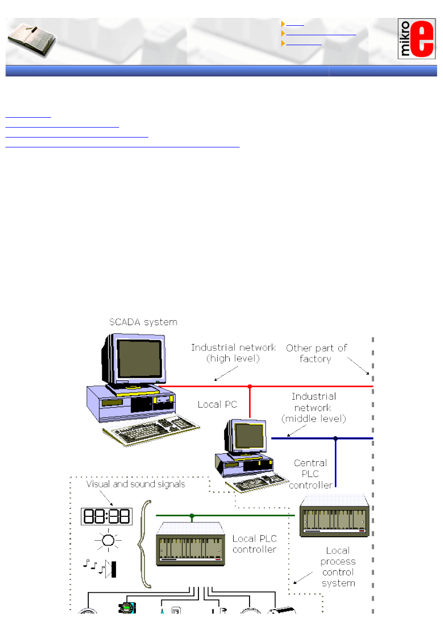
Generally speaking, process control system is made up of a group of electronic devices and equipment that provide
stability, accuracy and eliminate harmful transition statuses in production processes. Operating system can have
different form and implementation, from energy supply units to machines. As a result of fast progress in
technology, many complex operational tasks have been solved by connecting programmable logic controllers and
possibly a central computer. Beside connections with instruments like operating panels, motors, sensors, switches,
valves and such, possibilities for communication among instruments are so great that they allow high level of
exploitation and process coordination, as well as greater flexibility in realizing an process control system. Each
component of an process control system plays an important role, regardless of its size. For example, without a
sensor, PLC wouldn’t know what exactly goes on in the process. In automated system, PLC controller is usually the
central part of an process control system. With execution of a program stored in program memory, PLC
continuously monitors status of the system through signals from input devices. Based on the logic implemented in
the program, PLC determines which actions need to be executed with output instruments. To run more complex
processes it is possible to connect more PLC controllers to a central computer. A real system could look like the one
pictured below:
http://www.mikroelektronika.co.yu/english/product/books/PLCbook/chapter1/chapter1.htm (1 sur 3)05/11/2004 02:38:10
Chapter1
1.1 Conventional control panel
At the outset of industrial revolution, especially during sixties and seventies, relays were used to operate
automated machines, and these were interconnected using wires inside the control panel. In some cases a control
panel covered an entire wall. To discover an error in the system much time was needed especially with more
complex process control systems. On top of everything, a lifetime of relay contacts was limited, so some relays had
to be replaced. If replacement was required, machine had to be stopped and production too. Also, it could happen
that there was not enough room for necessary changes. control panel was used only for one particular process, and
it wasn’t easy to adapt to the requirements of a new system. As far as maintenance, electricians had to be very
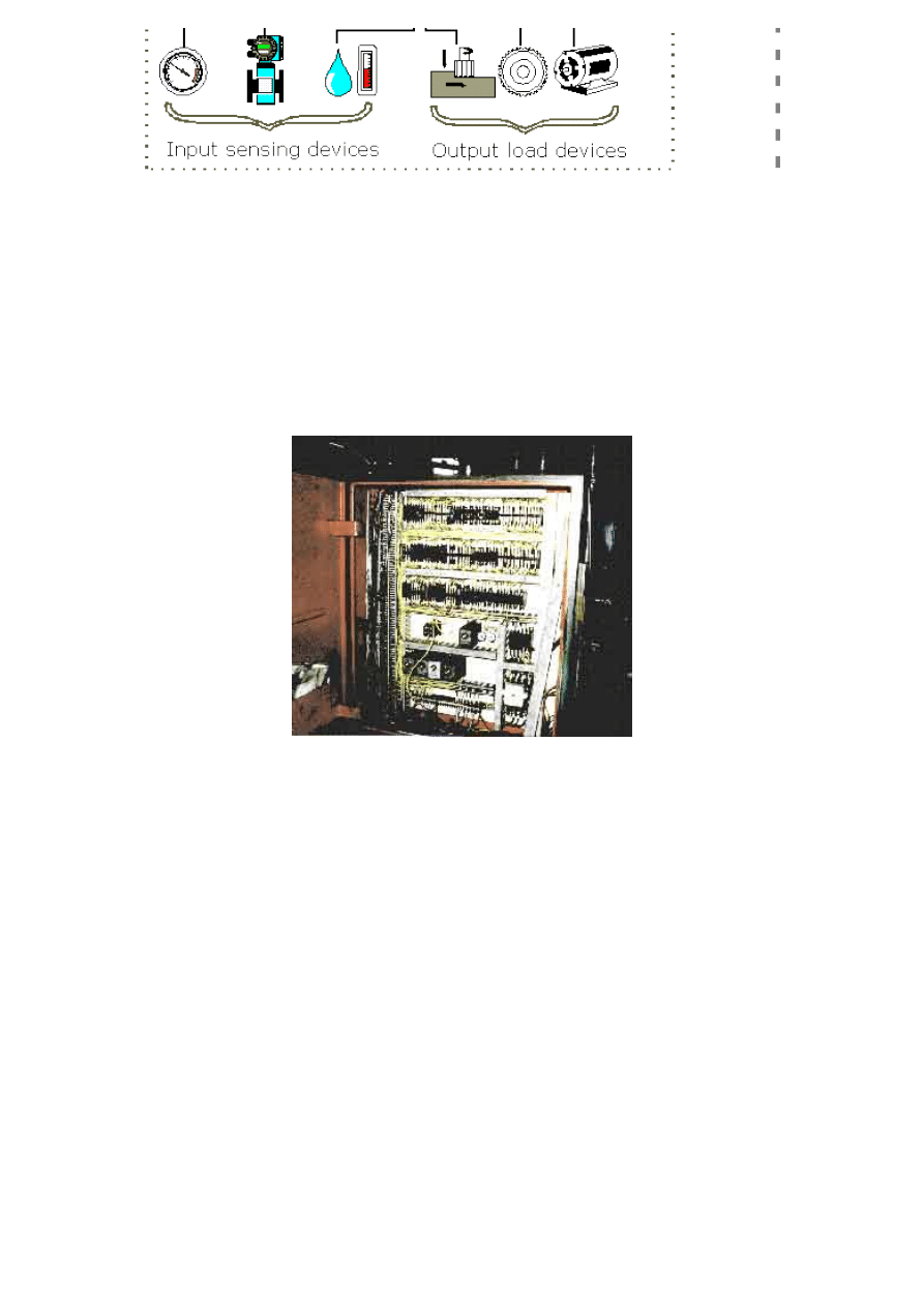
skillful in finding errors. In short, conventional control panels proved to be very inflexible. Typical example of
conventional control panel is given in the following picture.
In this photo you can notice a large number of electrical wires, time relays, timers and other elements of
automation typical for that period. Pictured control panel is not one of the more “complicated” ones, so you can
imagine what complex ones looked like.
Most frequently mentioned disadvantages of a classic control panel are:
- Too much work required in connecting wires
- Difficulty with changes or replacements
- Difficulty in finding errors; requiring skillful work force
- When a problem occurs, hold-up time is indefinite, usually long.
1.2 Control panel with a PLC controller
With invention of programmable controllers, much has changed in how an process control system is designed.
Many advantages appeared. Typical example of control panel with a PLC controller is given in the following picture.
http://www.mikroelektronika.co.yu/english/product/books/PLCbook/chapter1/chapter1.htm (2 sur 3)05/11/2004 02:38:11

Chapter1
Advantages of control panel that is based on a PLC controller can be presented in few basic points:
1. Compared to a conventional process control system, number of wires needed for connections is reduced by 80%
2. Consumption is greatly reduced because a PLC consumes less than a bunch of relays
3. Diagnostic functions of a PLC controller allow for fast and easy error detection.
4. Change in operating sequence or application of a PLC controller to a different operating process can easily be
accomplished by replacing a program through a console or using a PC software (not requiring changes in wiring,
unless addition of some input or output device is required).
5. Needs fewer spare parts
6. It is much cheaper compared to a conventional system, especially in cases where a large number of I/O
instruments are needed and when operational functions are complex.
7. Reliability of a PLC is greater than that of an electro-mechanical relay or a timer.
1.3 Systematic approach in designing an process control system
First, you need to select an instrument or a system that you wish to control. Automated system can be a machine
or a process and can also be called an process control system. Function of an process control system is constantly
watched by input devices (sensors) that give signals to a PLC controller. In response to this, PLC controller sends a
signal to external output devices (operative instruments) that actually control how system functions in an assigned
manner (for simplification it is recommended that you draw a block diagram of operations’ flow).
Secondly, you need to specify all input and output instruments that will be connected to a PLC controller. Input
devices are various switches, sensors and such. Output devices can be solenoids, electromagnetic valves, motors,
relays, magnetic starters as well as instruments for sound and light signalization.
Following an identification of all input and output instruments, corresponding designations are assigned to input
and output lines of a PLC controller. Allotment of these designations is in fact an allocation of inputs and outputs on
a PLC controller which correspond to inputs and outputs of a system being designed.
Third, make a ladder diagram for a program by following the sequence of operations that was determined in the
first step.
Finally, program is entered into the PLC controller memory. When finished with programming, checkup is done for
any existing errors in a program code (using functions for diagnostics) and, if possible, an entire operation is
simulated. Before this system is started, you need to check once again whether all input and output instruments
are connected to correct inputs or outputs. By bringing supply in, system starts working.
© Copyright 2003 mikroElektronika. A l l R i g h t s R e s e r v e d . F o r a n y c o m m e n t s c o n t a c t
.
http://www.mikroelektronika.co.yu/english/product/books/PLCbook/chapter1/chapter1.htm (3 sur 3)05/11/2004 02:38:11

Chapter2
Introduction to PLC controllers
on-line
FREE
!
Index
Development systems
Contact us
CHAPTER 2
Introduction to PLC controllers
Introduction
2.1 First programmed controllers
2.2 PLC controller parts
2.3 Central Processing unit -CPU
2.4 Memory
2.5 How to program a PLC controller
2.6 Power supply
2.7 Input to a PLC controller
2.8 Input adjustable interface
2.9 Output from a PLC controller
2.10 Output adjustable interface
2.11 Extension lines
Introduction
Industry has begun to recognize the need for quality improvement and increase in productivity in the sixties and
seventies. Flexibility also became a major concern (ability to change a process quickly became very important in
order to satisfy consumer needs).
Try to imagine automated industrial production line in the sixties and seventies. There was always a huge electrical
board for system controls, and not infrequently it covered an entire wall! Within this board there was a great
number of interconnected electromechanical relays to make the whole system work. By word "connected" it was
understood that electrician had to connect all relays manually using wires! An engineer would design logic for a
system, and electricians would receive a schematic outline of logic that they had to implement with relays. These
relay schemas often contained hundreds of relays. The plan that electrician was given was called "ladder
schematic". Ladder displayed all switches, sensors, motors, valves, relays, etc. found in the system. Electrician's
job was to connect them all together. One of the problems with this type of control was that it was based on
mechanical relays. Mechanical instruments were usually the weakest connection in the system due to their
moveable parts that could wear out. If one relay stopped working, electrician would have to examine an entire
system (system would be out until a cause of the problem was found and corrected).
The other problem with this type of control was in the system's break period when a system had to be turned off,
so connections could be made on the electrical board. If a firm decided to change the order of operations (make
even a small change), it would turn out to be a major expense and a loss of production time until a system was
functional again.
It's not hard to imagine an engineer who makes a few small errors during his project. It is also conceivable that
electrician has made a few mistakes in connecting the system. Finally, you can also imagine having a few bad
components. The only way to see if everything is all right is to run the system. As systems are usually not perfect
with a first try, finding errors was an arduous process. You should also keep in mind that a product could not be
made during these corrections and changes in connections. System had to be literally disabled before changes
were to be performed. That meant that the entire production staff in that line of production was out of work until
the system was fixed up again. Only when electrician was done finding errors and repairing,, the system was ready
for production. Expenditures for this kind of work were too great even for well-to-do companies.
2.1 First programmable controllers
"General Motors" is among the first who recognized a need to replace the system's "wired" control board.
Increased competition forced auto-makers to improve production quality and productivity. Flexibility and fast and
easy change of automated lines of production became crucial! General Motors' idea was to use for system logic one
of the microcomputers (these microcomputers were as far as their strength beneath today's eight-bit
microcontrollers) instead of wired relays. Computer could take place of huge, expensive, inflexible wired control
boards. If changes were needed in system logic or in order of operations, program in a microcomputer could be
changed instead of rewiring of relays. Imagine only what elimination of the entire period needed for changes in
wiring meant then. Today, such thinking is but common, then it was revolutionary!
http://www.mikroelektronika.co.yu/english/product/books/PLCbook/chapter2/chapter2.htm (1 sur 5)05/11/2004 02:38:50

Chapter2
Everything was well thought out, but then a new problem came up of how to make electricians accept and use a
new device. Systems are often quite complex and require complex programming. It was out of question to ask
electricians to learn and use computer language in addition to other job duties. General Motors Hidromatic Division
of this big company recognized a need and wrote out project criteria for first programmable logic controller ( there
were companies which sold instruments that performed industrial control, but those were simple sequential
controllers û not PLC controllers as we know them today). Specifications required that a new device be based on
electronic instead of mechanical parts, to have flexibility of a computer, to function in industrial environment
(vibrations, heat, dust, etc.) and have a capability of being reprogrammed and used for other tasks. The last
criteria was also the most important, and a new device had to be programmed easily and maintained by
electricians and technicians. When the specification was done, General Motors looked for interested companies, and
encouraged them to develop a device that would meet the specifications for this project.
"Gould Modicon" developed a first device which met these specifications. The key to success with a new device was
that for its programming you didn't have to learn a new programming language. It was programmed so that same
language ûa ladder diagram, already known to technicians was used. Electricians and technicians could very easily
understand these new devices because the logic looked similar to old logic that they were used to working with.
Thus they didn't have to learn a new programming language which (obviously) proved to be a good move. PLC
controllers were initially called PC controllers (programmable controllers). This caused a small confusion when
Personal Computers appeared. To avoid confusion, a designation PC was left to computers, and programmable
controllers became programmable logic controllers. First PLC controllers were simple devices. They connected
inputs such as switches, digital sensors, etc., and based on internal logic they turned output devices on or off.
When they first came up, they were not quite suitable for complicated controls such as temperature, position,
pressure, etc. However, throughout years, makers of PLC controllers added numerous features and improvements.
Today's PLC controller can handle highly complex tasks such as position control, various regulations and other
complex applications. The speed of work and easiness of programming were also improved. Also, modules for
special purposes were developed, like communication modules for connecting several PLC controllers to the net.
Today it is difficult to imagine a task that could not be handled by a PLC.
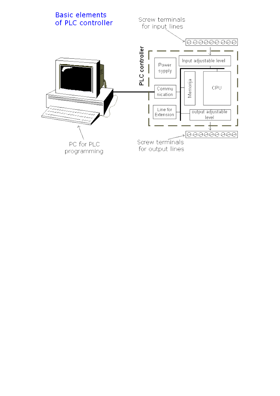
2.2 PLC controller components
PLC is actually an industrial microcontroller system (in more recent times we meet processors instead of
microcontrollers) where you have hardware and software specifically adapted to industrial environment. Block
schema with typical components which PLC consists of is found in the following picture. Special attention needs to
be given to input and output, because in these blocks you find protection needed in isolating a CPU blocks from
damaging influences that industrial environment can bring to a CPU via input lines. Program unit is usually a
computer used for writing a program (often in ladder diagram).
2.3 Central Processing Unit - CPU
Central Processing Unit (CPU) is the brain of a PLC controller. CPU itself is usually one of the microcontrollers.
Aforetime these were 8-bit microcontrollers such as 8051, and now these are 16- and 32-bit microcontrollers.
Unspoken rule is that you'll find mostly Hitachi and Fujicu microcontrollers in PLC controllers by Japanese makers,
Siemens in European controllers, and Motorola microcontrollers in American ones. CPU also takes care of
communication, interconnectedness among other parts of PLC controller, program execution, memory operation,
overseeing input and setting up of an output. PLC controllers have complex routines for memory checkup in order
to ensure that PLC memory was not damaged (memory checkup is done for safety reasons). Generally speaking,
CPU unit makes a great number of check-ups of the PLC controller itself so eventual errors would be discovered
early. You can simply look at any PLC controller and see that there are several indicators in the form of light diodes
for error signalization.
http://www.mikroelektronika.co.yu/english/product/books/PLCbook/chapter2/chapter2.htm (2 sur 5)05/11/2004 02:38:50
Chapter2
2.4 Memory
System memory (today mostly implemented in FLASH technology) is used by a PLC for an process control system.
Aside from this operating system it also contains a user program translated from a ladder diagram to a binary
form. FLASH memory contents can be changed only in case where user program is being changed. PLC controllers
were used earlier instead of FLASH memory and have had EPROM memory instead of FLASH memory which had to
be erased with UV lamp and programmed on programmers. With the use of FLASH technology this process was
greatly shortened. Reprogramming a program memory is done through a serial cable in a program for application
development.
User memory is divided into blocks having special functions. Some parts of a memory are used for storing input
and output status. The real status of an input is stored either as "1" or as "0" in a specific memory bit. Each input
or output has one corresponding bit in memory. Other parts of memory are used to store variable contents for
variables used in user program. For example, timer value, or counter value would be stored in this part of the
memory.
2.5 Programming a PLC controller
PLC controller can be reprogrammed through a computer (usual way), but also through manual programmers
(consoles). This practically means that each PLC controller can programmed through a computer if you have the
software needed for programming. Today's transmission computers are ideal for reprogramming a PLC controller in
factory itself. This is of great importance to industry. Once the system is corrected, it is also important to read the
right program into a PLC again. It is also good to check from time to time whether program in a PLC has not
changed. This helps to avoid hazardous situations in factory rooms (some automakers have established
communication networks which regularly check programs in PLC controllers to ensure execution only of good
programs).
Almost every program for programming a PLC controller possesses various useful options such as: forced switching
on and off of the system inputs/ouputs (I/O lines), program follow up in real time as well as documenting a
diagram. This documenting is necessary to understand and define failures and malfunctions. Programmer can add
remarks, names of input or output devices, and comments that can be useful when finding errors, or with system
maintenance. Adding comments and remarks enables any technician (and not just a person who developed the
system) to understand a ladder diagram right away. Comments and remarks can even quote precisely part
numbers if replacements would be needed. This would speed up a repair of any problems that come up due to bad
parts. The old way was such that a person who developed a system had protection on the program, so nobody
aside from this person could understand how it was done. Correctly documented ladder diagram allows any
technician to understand thoroughly how system functions.
2.6. Power supply
http://www.mikroelektronika.co.yu/english/product/books/PLCbook/chapter2/chapter2.htm (3 sur 5)05/11/2004 02:38:50
Chapter2
Electrical supply is used in bringing electrical energy to central processing unit. Most PLC controllers work either at
24 VDC or 220 VAC. On some PLC controllers you'll find electrical supply as a separate module. Those are usually
bigger PLC controllers, while small and medium series already contain the supply module. User has to determine
how much current to take from I/O module to ensure that electrical supply provides appropriate amount of current.
Different types of modules use different amounts of electrical current.
This electrical supply is usually not used to start external inputs or outputs. User has to provide separate supplies
in starting PLC controller inputs or outputs because then you can ensure so called "pure" supply for the PLC
controller. With pure supply we mean supply where industrial environment can not affect it damagingly. Some of
the smaller PLC controllers supply their inputs with voltage from a small supply source already incorporated into a
PLC.
2.7 PLC controller inputs
Intelligence of an automated system depends largely on the ability of a PLC controller to read signals from different
types of sensors and input devices. Keys, keyboards and by functional switches are a basis for man versus machine
relationship. On the other hand, in order to detect a working piece, view a mechanism in motion, check pressure or
fluid level you need specific automatic devices such as proximity sensors, marginal switches, photoelectric sensors,
level sensors, etc. Thus, input signals can be logical (on/off) or analogue. Smaller PLC controllers usually have only
digital input lines while larger also accept analogue inputs through special units attached to PLC controller. One of
the most frequent analogue signals are a current signal of 4 to 20 mA and milivolt voltage signal generated by
various sensors. Sensors are usually used as inputs for PLCs. You can obtain sensors for different purposes. They
can sense presence of some parts, measure temperature, pressure, or some other physical dimension, etc. (ex.
inductive sensors can register metal objects).
Other devices also can serve as inputs to PLC controller. Intelligent devices such as robots, video systems, etc.
often are capable of sending signals to PLC controller input modules (robot, for instance, can send a signal to PLC
controller input as information when it has finished moving an object from one place to the other.)
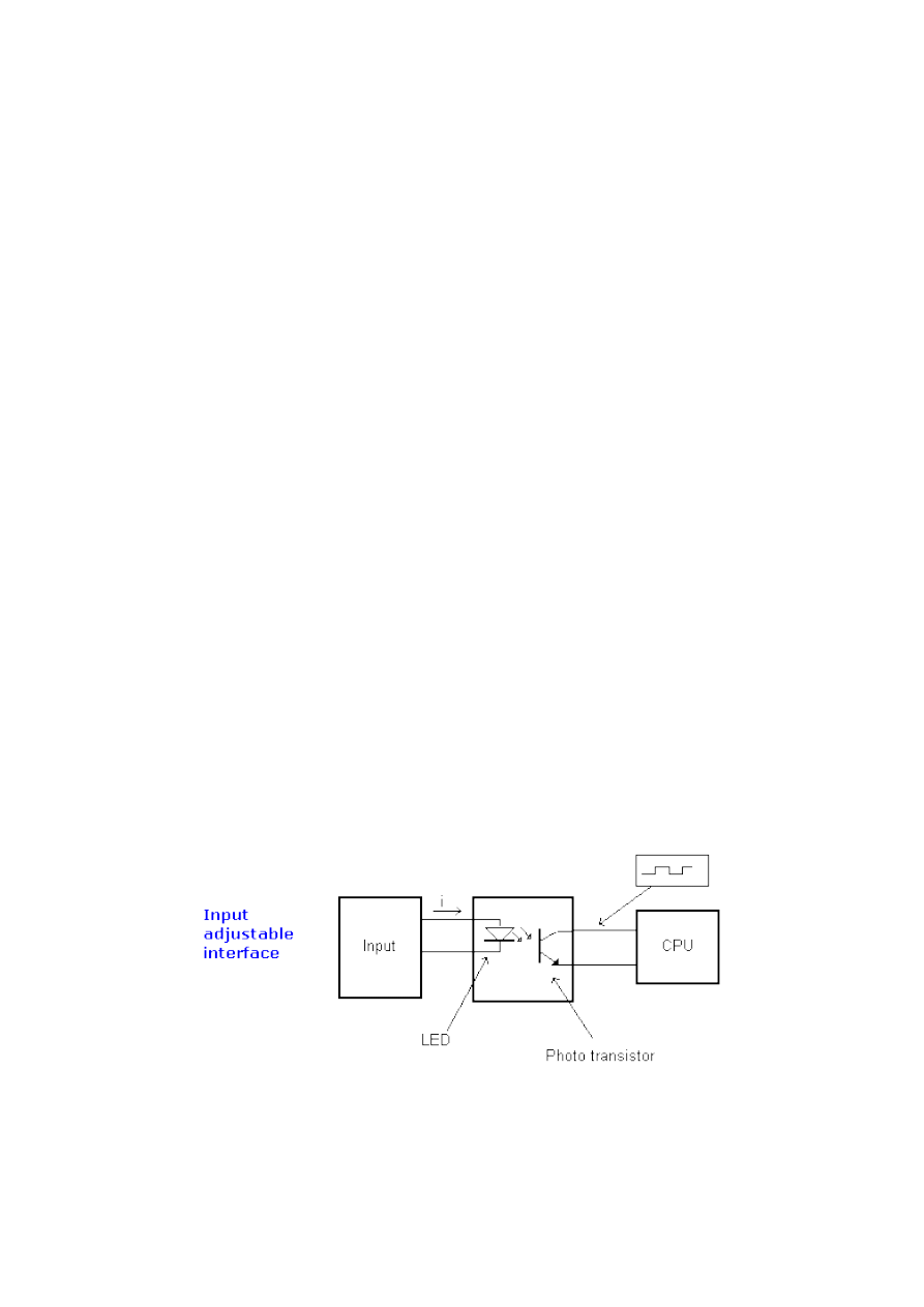
2.8 Input adjustment interface
Adjustment interface also called an interface is placed between input lines and a CPU unit. The purpose of
adjustment interface to protect a CPU from disproportionate signals from an outside world. Input adjustment
module turns a level of real logic to a level that suits CPU unit (ex. input from a sensor which works on 24 VDC
must be converted to a signal of 5 VDC in order for a CPU to be able to process it). This is typically done through
opto-isolation, and this function you can view in the following picture.
Opto-isolation means that there is no electrical connection between external world and CPU unit. They are
"optically" separated, or in other words, signal is transmitted through light. The way this works is simple. External
device brings a signal which turns LED on, whose light in turn incites photo transistor which in turn starts
conducting, and a CPU sees this as logic zero (supply between collector and transmitter falls under 1V). When input
signal stops LED diode turns off, transistor stops conducting, collector voltage increases, and CPU receives logic 1
as information.
2.9 PLC controller output
Automated system is incomplete if it is not connected with some output devices. Some of the most frequently used
devices are motors, solenoids, relays, indicators, sound signalization and similar. By starting a motor, or a relay,
PLC can manage or control a simple system such as system for sorting products all the way up to complex systems
such as service system for positioning head of CNC machine. Output can be of analogue or digital type. Digital
output signal works as a switch; it connects and disconnects line. Analogue output is used to generate the
analogue signal (ex. motor whose speed is controlled by a voltage that corresponds to a desired speed).
http://www.mikroelektronika.co.yu/english/product/books/PLCbook/chapter2/chapter2.htm (4 sur 5)05/11/2004 02:38:50
Chapter2
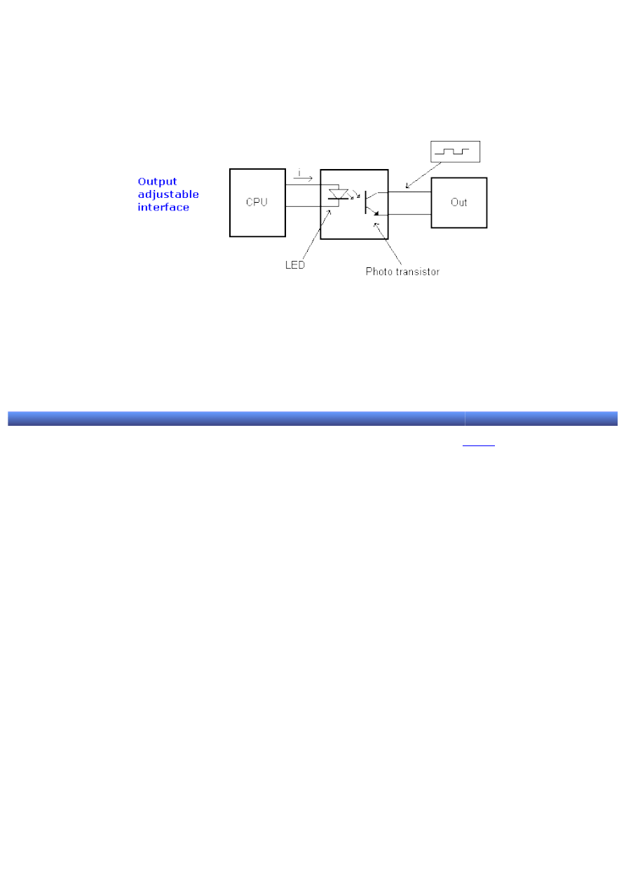
2.10 Output adjustment interface
Output interface is similar to input interface. CPU brings a signal to LED diode and turns it on. Light incites a photo
transistor which begins to conduct electricity, and thus the voltage between collector and emmiter falls to 0.7V ,
and a device attached to this output sees this as a logic zero. Inversely it means that a signal at the output exists
and is interpreted as logic one. Photo transistor is not directly connected to a PLC controller output. Between photo
transistor and an output usually there is a relay or a stronger transistor capable of interrupting stronger signals.
2.11 Extension lines
Every PLC controller has a limited number of input/output lines. If needed this number can be increased through
certain additional modules by system extension through extension lines. Each module can contain extension both
of input and output lines. Also, extension modules can have inputs and outputs of a different nature from those on
the PLC controller (ex. in case relay outputs are on a controller, transistor outputs can be on an extension module).
© Copyright 2003 mikroElektronika. A l l R i g h t s R e s e r v e d . F o r a n y c o m m e n t s c o n t a c t
.
http://www.mikroelektronika.co.yu/english/product/books/PLCbook/chapter2/chapter2.htm (5 sur 5)05/11/2004 02:38:50

Chapter3
Introduction to PLC controllers
on-line
FREE
!
Index
Development systems
Contact us
CHAPTER 3
Connecting sensors and execution devices
Introduction
3.1 Sinking-sourcing concept
3.2 Input lines
3.3 Output lines
Introduction
Connecting external devices to a PLC controller regardless whether they are input or output is a special subject
matter for industry. If it stands alone, PLC controller itself is nothing. In order to function it needs sensors to obtain
information from environment, and it also needs execution devices so it could turn the programmed change into a
reality. Similar concept is seen in how human being functions. Having a brain is simply not enough. Humans
achieve full activity only with processing of information from a sensor (eyes, ears, touch, smell) and by taking
action through hands, legs or some tools. Unlike human being who receives his sensors automatically, when
dealing with controllers, sensors have to be subsequently connected to a PLC. How to connect input and output
parts is the topic of this chapter.
3.1 Sinking-Sourcing Concept
PLC has input and output lines through which it is connected to a system it directs. Input can be keys, switches,
sensors while outputs are led to different devices from simple signalization lights to complex communication
modules.
This is a very important part of the story about PLC controllers because it directly influences what can be
connected and how it can be connected to controller inputs or outputs. Two terms most frequently mentioned when
discussing connections to inputs or outputs are "sinking" and "sourcing". These two concepts are very important in
connecting a PLC correctly with external environment. The most brief definition of these two concepts would be:
SINKING = Common GND line (-)
SOURCING = Common VCC line (+)
First thing that catches one's eye are "+" and "-" supply, DC supply. Inputs and outputs which are either sinking or
sourcing can conduct electricity only in one direction, so they are only supplied with direct current.
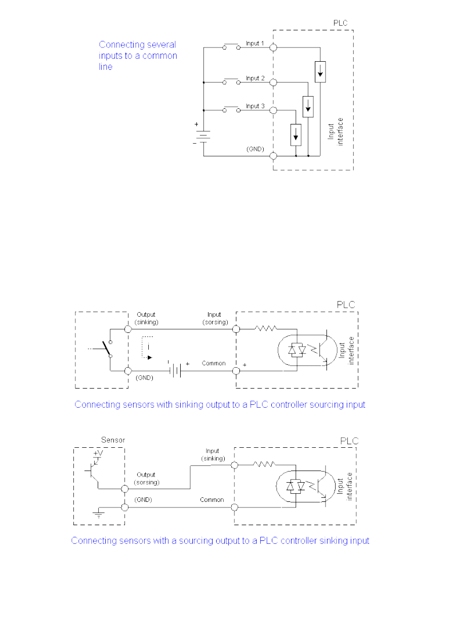
According to what we've said thus far, each input or output has its own return line, so 5 inputs would need 10
screw terminals on PLC controller housing. Instead, we use a system of connecting several inputs to one return line
as in the following picture. These common lines are usually marked "COMM" on the PLC controller housing.
http://www.mikroelektronika.co.yu/english/product/books/PLCbook/chapter3/chapter3.htm (1 sur 4)05/11/2004 02:39:15
Chapter3
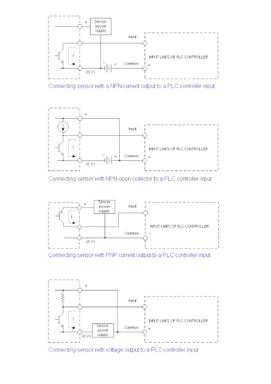
3.2 Input lines
Explanation of PLC controller input and output lines has up to now been given only theoretically. In order to apply
this knowledge, we need to make it a little more specific. Example can be connection of external device such as
proximity sensor. Sensor outputs can be different depending on a sensor itself and also on a particular application.
Following pictures display some examples of sensor outputs and their connection with a PLC controller. Sensor
output actually marks the size of a signal given by a sensor at its output when this sensor is active. In one case
this is +V (supply voltage, usually 12 or 24V) and in other case a GND (0V). Another thing worth mentioning is
that sinking-sourcing and sourcing - sinking pairing is always used, and not sourcing-sourcing or sinking-sinking
pairing.
If we were to make type of connection more specific, we'd get combinations as in following pictures (for more
specific connection schemas we need to know the exact sensor model and a PLC controller model).
http://www.mikroelektronika.co.yu/english/product/books/PLCbook/chapter3/chapter3.htm (2 sur 4)05/11/2004 02:39:15
Chapter3
http://www.mikroelektronika.co.yu/english/product/books/PLCbook/chapter3/chapter3.htm (3 sur 4)05/11/2004 02:39:15
Chapter3
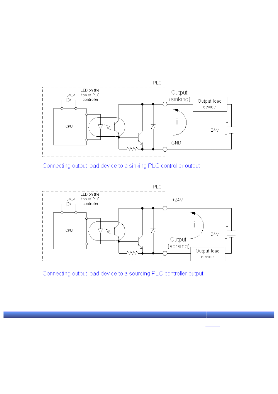
3.3 Output lines
PLC controller output lines usually can be:
-transistors in PNP connection
-transistors in NPN connection
-relays
The following two pictures display a realistic way how a PLC manages external devices. It ought to be noted that a
main difference between these two pictures is a position of "output load device". By "output load device" we mean
some relay, signalization light or similar.
How something is connected with a PLC output depends on the element being connected. In short, it depends on
whether this element of output load device is activated by a positive supply pole or a negative supply pole.
© Copyright 2003 mikroElektronika. A l l R i g h t s R e s e r v e d . F o r a n y c o m m e n t s c o n t a c t
.
http://www.mikroelektronika.co.yu/english/product/books/PLCbook/chapter3/chapter3.htm (4 sur 4)05/11/2004 02:39:15

Chapter4
Introduction to PLC controllers
on-line
FREE
!
Index
Development systems
Contact us
CHAPTER 4
Architecture of specific PLC controller
Introduction
4.1 Why OMRON?
4.2 CPM1A PLC controller
4.3 PLC controller input lines
4.4 PLC controller output lines
4.5 How PLC controller works
4.6 CPM1A PLC controller memory map
4.7 Timers and counters
Introduction
This book could deal with a general overview of some supposed PLC controller. Author has had an opportunity to
look over plenty of books published up till now, and this approach is not the most suitable to the purposes of this
book in his opinion. Idea of this book is to work through one specific PLC controller where someone can get a real
feeling on this subject and its weight. Our desire was to write a book based on whose reading you can earn some
money. After all, money is the end goal of every business!
4.1 Why OMRON?
Why not? It is a huge company which has high quality and by our standards inexpensive controllers. Today we can
say almost with surety that PLC controllers by manufacturers round the world are excellent devices, and altogether
similar. Nevertheless, for specific application we need to know specific information about a PLC controller being
used. Therefore, the choice fell on OMRON company and its PLC of micro class CPM1A. Adjective "micro" itself
implies the smallest models from the viewpoint of a number of attached lines or possible options. Still, this PLC
controller is ideal for the purposes of this book, and that is to introduce a PLC controller philosophy to its readers.
4.2 CPM1A PLC controller
Each PLC is basically a microcontroller system (CPU of PLC controller is based on one of the microcontrollers, and
in more recent times on one of the PC processors) with peripherals that can be digital inputs, digital outputs or
relays as in our case. However, this is not an "ordinary" microcontroller system. Large teams have worked on it,
and a checkup of its function has been performed in real world under all possible circumstances. Software itself is
entirely different from assemblers used thus far, such as BASIC or C. This specialized software is called
"ladder" (name came about by an association of program's configuration which resembles a ladder, and from the
way program is written out).
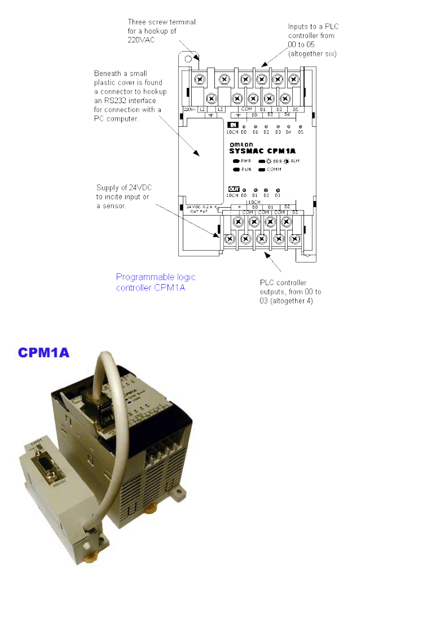
Specific look of CPM1A PLC controller can be seen in the following picture. On the upper surface, there are 4 LED
indicators and a connection port with an RS232 module which is interface to a PC computer. Aside from this, screw
terminals and light indicators of activity of each input or output are visible on upper and lower sides. Screw
terminals serve to manually connect to a real system. Hookups L1 and L2 serve as supply which is 220V~ in this
case. PLC controllers that work on power grid voltage usually have a source of direct supply of 24 VDC for
supplying sensors and such (with a CPM1A source of direct supply is found on the bottom left hand side and is
represented with two screw terminals. Controller can be mounted to industrial "track" along with other automated
elements, but also by a screw to the machine wall or control panel.
http://www.mikroelektronika.co.yu/english/product/books/PLCbook/chapter4/chapter4.htm (1 sur 9)05/11/2004 02:39:57
Chapter4
Controller is 8cm high and divided vertically into two
areas: a lower one with a converter of 220V~ at 24VDC
and other voltages needed for running a CPU unit; and,
upper area with a CPU and memory, relays and digital
inputs.
When you lift the small plastic cover you'll see a
connector to which an RS232 module is hooked up for
serial interface with a computer. This module is used
when programming a PLC controller to change programs
or execution follow-up. When installing a PLC it isn't
necessary to install this module, but it is recommended
because of possible changes in software during
operation.
http://www.mikroelektronika.co.yu/english/product/books/PLCbook/chapter4/chapter4.htm (2 sur 9)05/11/2004 02:39:57
Chapter4
To better inform programmers on PLC controller status, maker has provided for four light indicators in the form of
LED's. Beside these indicators, there are status indicators for each individual input and output. These LED's are
found by the screw terminals and with their status are showing input or output state. If input/output is active,
diode is lit and vice versa.
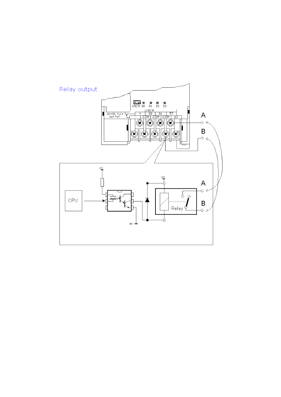
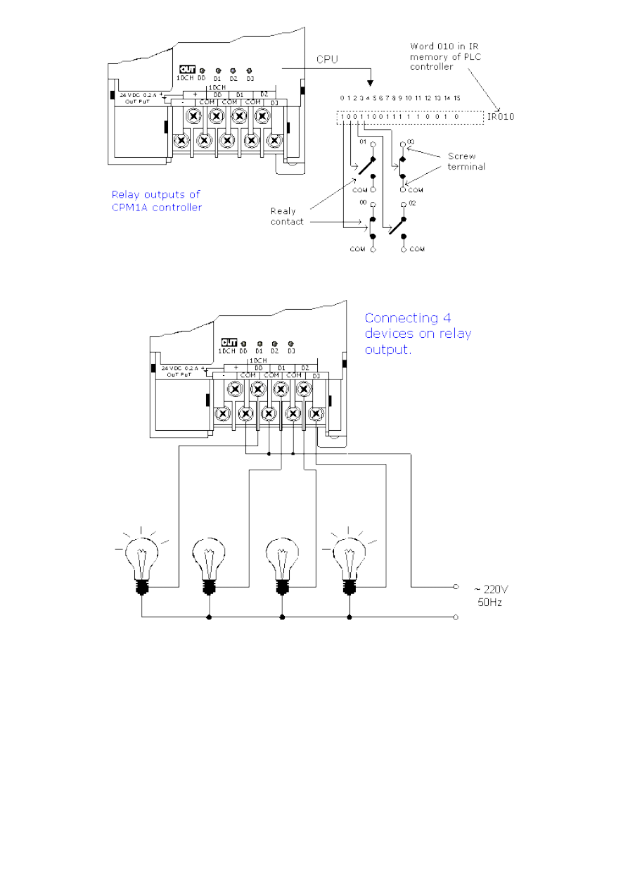
4.3 PLC controller output lines
Aside from transistor outputs in PNP and NPN connections, PLC can also have relays as outputs. Existence of relays
as outputs makes it easier to connect with external devices. Model CPM1A contains exactly these relays as outputs.
There a 4 relays whose functional contacts are taken out on a PLC controller housing in the form of screw
terminals. In reality this looks as in picture below.
With activation of phototransistor, relay comes under voltage and activates a contact between points A and B.
Contacts A and B can in our case be either in connection or interrupted. What state these contacts are in is
determined by a CPU through appropriate bits in memory location IR010. One example of relay status is shown in
a picture below. A true state of devices attached to these relays is displayed.
http://www.mikroelektronika.co.yu/english/product/books/PLCbook/chapter4/chapter4.htm (3 sur 9)05/11/2004 02:39:57
Chapter4
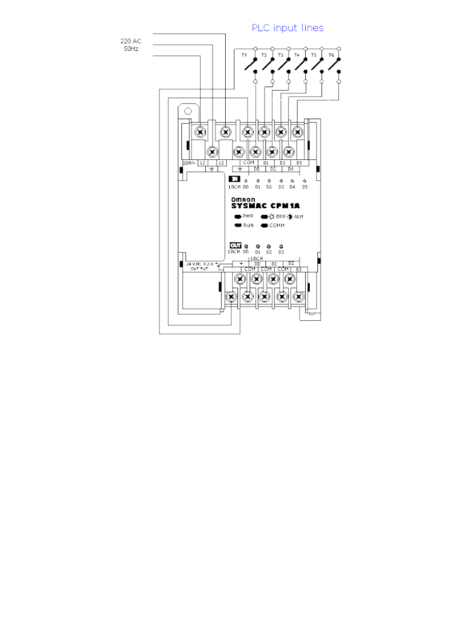
4.4 PLC controller input lines
Different sensors, keys, switches and other elements that can change status of a joined bit at PLC input can be
hooked up to the PLC controller inputs. In order to realize a change, we need a voltage source to incite an input.
The simplest possible input would be a common key. As CPM1A PLC has a source of direct voltage of 24V, the
same source can be used to incite input (problem with this source is its maximum current which it can give
continually and which in our case amounts to 0.2A). Since inputs to a PLC are not big consumers (unlike some
sensor where a stronger external supply must be used) it is possible to take advantage of the existing source of
direct supply to incite all six keys.
http://www.mikroelektronika.co.yu/english/product/books/PLCbook/chapter4/chapter4.htm (4 sur 9)05/11/2004 02:39:57
Chapter4
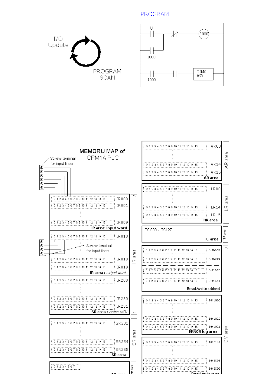
4.5 How PLC controller works
Basis of a PLC function is continual scanning of a program. Under scanning we mean running through all conditions
within a guaranteed period. Scanning process has three basic steps:
Step 1.
Testing input status. First, a PLC checks each of the inputs with intention to see which one of them has status ON
or OFF. In other words, it checks whether a sensor, or a switch etc. connected with an input is activated or not.
Information that processor thus obtains through this step is stored in memory in order to be used in the following
step.
Step 2.
Program execution. Here a PLC executes a program, instruction by instruction. Based on a program and based on
the status of that input as obtained in the preceding step, an appropriate action is taken. This reaction can be
defined as activation of a certain output, or results can be put off and stored in memory to be retrieved later in the
following step.
Step 3.
Checkup and correction of output status. Finally, a PLC checks up output status and adjusts it as needed. Change is
performed based on the input status that had been read during the first step, and based on the results of program
execution in step two. Following the execution of step 3 PLC returns to the beginning of this cycle and continually
repeats these steps. Scanning time is defined by the time needed to perform these three steps, and sometimes it
is an important program feature.
http://www.mikroelektronika.co.yu/english/product/books/PLCbook/chapter4/chapter4.htm (5 sur 9)05/11/2004 02:39:57
Chapter4
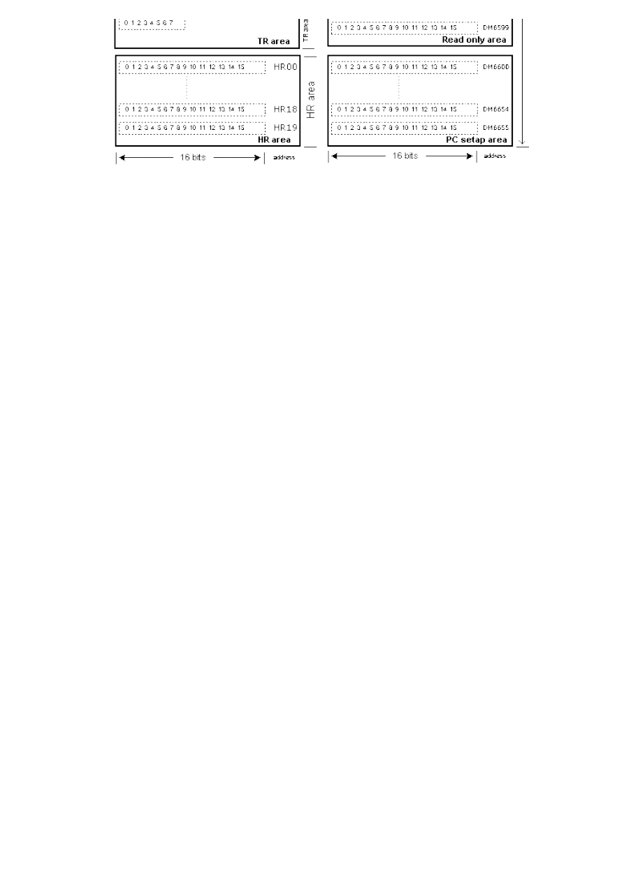
4.6 CPM1A PLC controller memory map
By memory map we mean memory structure for a PLC controller. Simply said, certain parts of memory have
specific roles. If you look at the picture below, you can see that memory for CPM1A is structured into 16-bit words.
A cluster of several such words makes up a region. All the regions make up the memory for a PLC controller.
http://www.mikroelektronika.co.yu/english/product/books/PLCbook/chapter4/chapter4.htm (6 sur 9)05/11/2004 02:39:57
Chapter4
Unlike microcontroller systems where only some memory locations have had their purpose clearly defined (ex.
register that contains counter value), a memory of PLC controller is completely defined, and more importantly
almost entire memory is addressable in bits. Addressability in bits means that it is enough to write the address of
the memory location and a number of bits after it in order to manipulate with it. In short, that would mean that
something like this could be written: "201.7=1" which would clearly indicate a word 201 and its bit 7 which is set
to one.
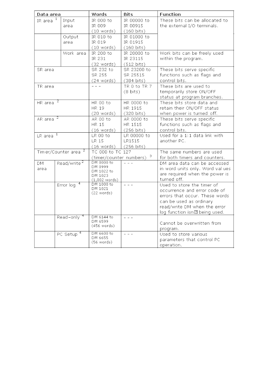
IR region
Memory locations intended for PLC input and output. Some bits are directly connected to PLC controller inputs and
outputs (screw terminal). In our case, we have 6 input lines at address IR000. One bit corresponds to each line, so
the first line has the address IR000.0, and the sixth IR000.5. When you obtain a signal at the input, this
immediately affects the status of a corresponding bit. There are also words with work bits in this region, and these
work bits are used in a program as flags or certain conditional bits.
SR region
Special memory region for control bits and flags. It is intended first and foremost for counters and interrupts. For
example, SR250 is memory location which contains an adjustable value, adjusted by potentiometer no.0 (in other
words, value of this location can be adjusted manually by turning a potentiometer no.0.
TR region
When you move to a subprogram during program execution, all relevant data is stored in this region up to the
return from a subprogram.
HR region
It is of great importance to keep certain information even when supply stops. This part of the memory is battery
supported, so even when supply has stopped it will keep all data found therein before supply stopped.
AR region
This is one more region with control bits and flags. This region contains information on PLC status, errors, system
time, and the like. Like HR region, this one is also battery supported.
LR region
In case of connection with another PLC, this region is used for exchange of data.
Timer and counter region
This region contains timer and counter values. There are 128 values. Since we will consider examples with timers
and counters, we will discus this region more later on.
DM region
Contains data related to setting up communication with a PC computer, and data on errors.
Each region can be broken down to single words and meanings of its bits. In order to keep the clarity of the book,
this part is dealt with in Attachments and we will deal with those regions here whose bits are mostly used for
writing.
http://www.mikroelektronika.co.yu/english/product/books/PLCbook/chapter4/chapter4.htm (7 sur 9)05/11/2004 02:39:57
Chapter4
Note:
1. IR and LR bits that are not used for their allocated functions can be used as work bits.
2. The contents of the HR area, LR area, Counter area, and read/write DM area are backed up by a capacitor. At 25 oC, the capacitor will
back up memory for 20 days.
3. When accessing a PV, TC numbers are used as word data; when accessing Completing Flags, they are used as bit data.
4. Data in DM6144 to DM6655 cannot be overwritten from the program, but they can be changed from a Peripheral Device
4.7 Timers and counters
Timers and counters are indispensable in PLC programming. Industry has to number its products, determine a
needed action in time, etc. Timing functions is very important, and cycle periods are critical in many processes.
There are two types of timers delay-off and delay-on. First is late with turn off and the other runs late in turning on
in relation to a signal that activated timers. Example of a delay-off timer would be staircase lighting. Following its
activation, it simply turns off after few minutes.
Each timer has a time basis, or more precisely has several timer basis. Typical values are: 1 second, 0.1 second,
and 0,01 second. If programmer has entered .1 as time basis and 50 as a number for delay increase, timer will
have a delay of 5 seconds (50 x 0.1 second = 5 seconds).
http://www.mikroelektronika.co.yu/english/product/books/PLCbook/chapter4/chapter4.htm (8 sur 9)05/11/2004 02:39:57

Chapter4
Timers also have to have value SV set in advance. Value set in advance or ahead of time is a number of
increments that timer has to calculate before it changes the output status. Values set in advance can be constants
or variables. If a variable is used, timer will use a real time value of the variable to determine a delay. This enables
delays to vary depending on the conditions during function. Example is a system that has produced two different
products, each requiring different timing during process itself. Product A requires a period of 10 seconds, so
number 10 would be assigned to the variable. When product B appears, a variable can change value to what is
required by product B.
Typically, timers have two inputs. First is timer enable, or conditional input (when this input is activated, timer will
start counting). Second input is a reset input. This input has to be in OFF status in order for a timer to be active, or
the whole function would be repeated over again. Some PLC models require this input to be low for a timer to be
active, other makers require high status (all of them function in the same way basically). However, if reset line
changes status, timer erases accumulated value.
With a PLC controller by Omron there are two types of timers: TIM and TIMH. TIM timer measures in increments of
0.1 seconds. It can measure from 0 to 999.9 seconds with precision of 0.1 seconds more or less.
Quick timer (TIMH) measures in increments of 0.01 seconds. Both timers are "delay-on" timers of a lessening-
style. They require assignment of a timer number and a set value (SV). When SV runs out, timer output turns on.
Numbers of a timing counter refer to specific address in memory and must not be duplicated (same number can
not be used for a timer and a counter).
© Copyright 2003 mikroElektronika. A l l R i g h t s R e s e r v e d . F o r a n y c o m m e n t s c o n t a c t
.
http://www.mikroelektronika.co.yu/english/product/books/PLCbook/chapter4/chapter4.htm (9 sur 9)05/11/2004 02:39:57
Chapter5
Introduction to PLC controllers
on-line
FREE
!
Index
Development systems
Contact us
CHAPTER 5
Ladder diagram
Introduction
5.1 Ladder diagram
5.2 Normally open and normally closed contacts
5.3 Brief example
Introduction
Programmable controllers are generally programmed in ladder diagram (or "relay diagram") which is nothing but a
symbolic representation of electric circuits. Symbols were selected that actually looked similar to schematic
symbols of electric devices, and this has made it much easier for electricians to switch to programming PLC
controllers. Electrician who has never seen a PLC can understand a ladder diagram.
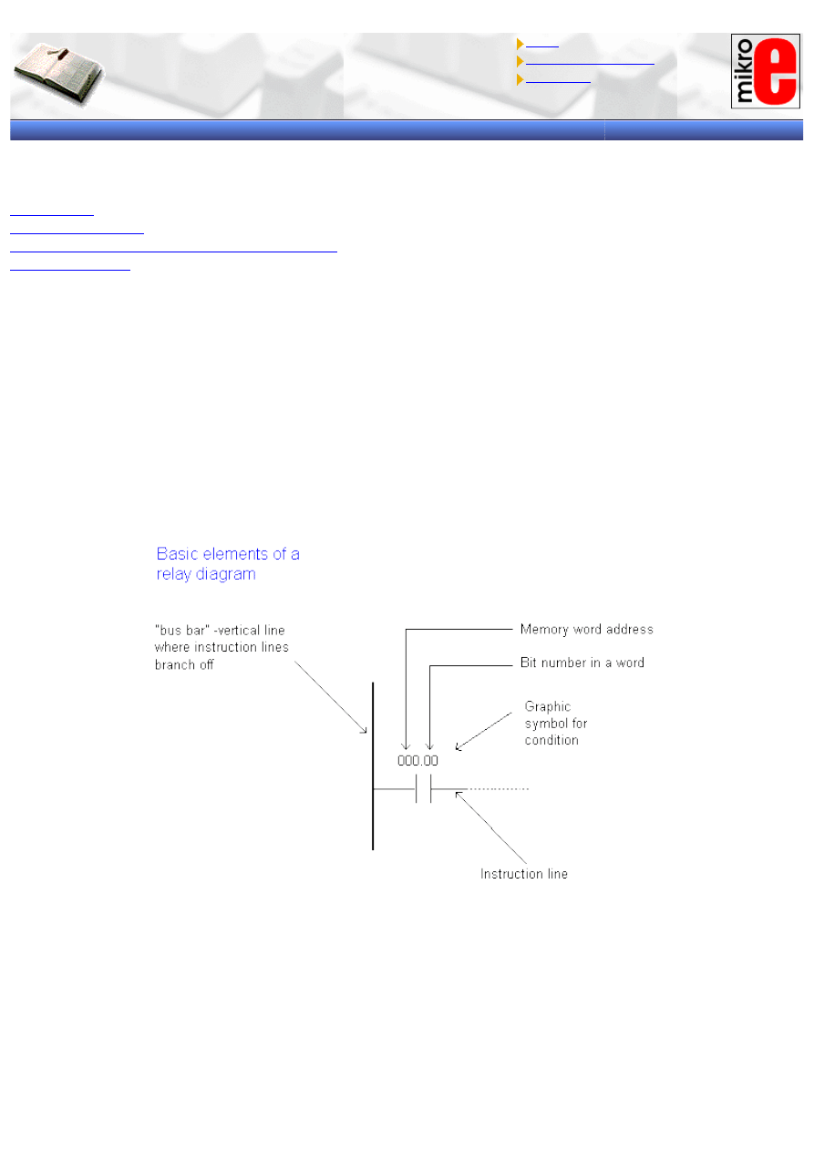
5.1 Ladder diagram
There are several languages designed for user communication with a PLC, among which ladder diagram is the most
popular. Ladder diagram consists of one vertical line found on the left hand side, and lines which branch off to the
right. Line on the left is called a "bus bar", and lines that branch off to the right are instruction lines. Conditions
which lead to instructions positioned at the right edge of a diagram are stored along instruction lines. Logical
combination of these conditions determines when and in what way instruction on the right will execute. Basic
elements of a relay diagram can be seen in the following picture.
Most instructions require at least one operand, and often more than one. Operand can be some memory location,
one memory location bit, or some numeric value -number. In the example above, operand is bit 0 of memory
location IR000. In a case when we wish to proclaim a constant as an operand, designation # is used beneath the
numeric writing (for a compiler to know it is a constant and not an address.)
Based on the picture above, one should note that a ladder diagram consists of two basic parts: left section also
called conditional, and a right section which has instructions. When a condition is fulfilled, instruction is executed,
and that's all!
http://www.mikroelektronika.co.yu/english/product/books/PLCbook/chapter5/chapter5.htm (1 sur 5)05/11/2004 02:40:24
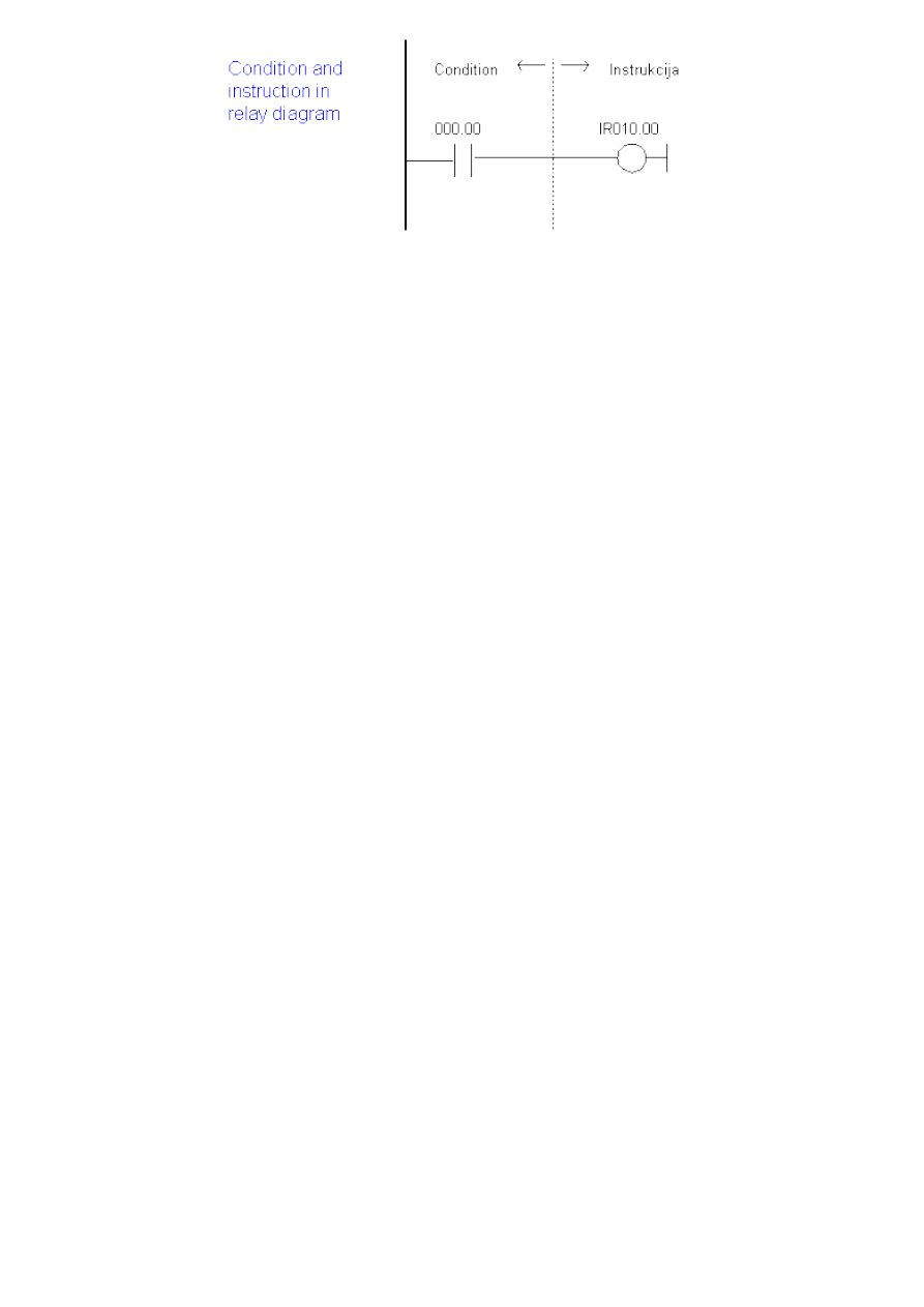
Chapter5
Picture above represents a example of a ladder diagram where relay is activated in PLC controller when signal
appears at input line 00. Vertical line pairs are called conditions. Each condition in a ladder diagram has a value ON
or OFF, depending on a bit status assigned to it. In this case, this bit is also physically present as an input line
(screw terminal) to a PLC controller. If a key is attached to a corresponding screw terminal, you can change bit
status from a logic one status to a logic zero status, and vice versa. Status of logic one is usually designated as
"ON", and status of logic zero as "OFF".
Right section of a ladder diagram is an instruction which is executed if left condition is fulfilled. There are several
types of instructions that could easily be divided into simple and complex. Example of a simple instruction is
activation of some bit in memory location. In the example above, this bit has physical connotation because it is
connected with a relay inside a PLC controller. When a CPU activates one of the leading four bits in a word IR010,
relay contacts move and connect lines attached to it. In this case, these are the lines connected to a screw
terminal marked as 00 and to one of COM screw terminals.
5.2 Normally open and normally closed contacts
Since we frequently meet with concepts "normally open" and "normally closed" in industrial environment, it's
important to know them. Both terms apply to words such as contacts, input, output, etc. (all combinations have
the same meaning whether we are talking about input, output, contact or something else).
Principle is quite simple, normally open switch won't conduct electricity until it is pressed down, and normally
closed switch will conduct electricity until it is pressed. Good examples for both situations are the doorbell and a
house alarm.
If a normally closed switch is selected, bell will work continually until someone pushes the switch. By pushing a
switch, contacts are opened and the flow of electricity towards the bell is interrupted. Of course, system so
designed would not in any case suit the owner of the house. A better choice would certainly be a normally open
switch. This way bell wouldn't work until someone pushed the switch button and thus informed of his or her
presence at the entrance.
Home alarm system is an example of an application of a normally closed switch. Let's suppose that alarm system is
intended for surveillance of the front door to the house. One of the ways to "wire" the house would be to install a
normally open switch from each door to the alarm itself (precisely as with a bell switch). Then, if the door was
opened, this would close the switch, and an alarm would be activated. This system could work, but there would be
some problems with this, too. Let's suppose that switch is not working, that a wire is somehow disconnected, or a
switch is broken, etc. (there are many ways in which this system could become dysfunctional). The real trouble is
that a homeowner would not know that a system was out of order. A burglar could open the door, a switch would
not work, and the alarm would not be activated. Obviously, this isn't a good way to set up this system. System
should be set up in such a way so the alarm is activated by a burglar, but also by its own dysfunction, or if any of
the components stopped working. (A homeowner would certainly want to know if a system was dysfunctional).
Having these things in mind, it is far better to use a switch with normally closed contacts which will detect an
unauthorized entrance (opened door interrupts the flow of electricity, and this signal is used to activate a sound
signal), or a failure on the system such as a disconnected wire. These considerations are even more important in
industrial environment where a failure could cause injury at work. One such example where outputs with normally
closed contacts are used is a safety wall with trimming machines. If the wall doors open, switch affects the output
with normally closed contacts and interrupts a supply circuit. This stops the machine and prevents an injury.
Concepts normally open and normally closed can apply to sensors as well. Sensors are used to sense the presence
of physical objects, measure some dimension or some amount. For instance, one type of sensors can be used to
detect presence of a box on an industry transfer belt. Other types can be used to measure physical dimensions
such as heat, etc. Still, most sensors are of a switch type. Their output is in status ON or OFF depending on what
the sensor "feels". Let's take for instance a sensor made to feel metal when a metal object passes by the sensor.
For this purpose, a sensor with a normally open or a normally closed contact at the output could be used. If it were
http://www.mikroelektronika.co.yu/english/product/books/PLCbook/chapter5/chapter5.htm (2 sur 5)05/11/2004 02:40:24
Chapter5
necessary to inform a PLC each time an object passed by the sensor, a sensor with a normally open output should
be selected. Sensor output would set off only if a metal object were placed right before the sensor. A sensor would
turn off after the object has passed. PLC could then calculate how many times a normally open contact was set off
at the sensor output, and would thus know how many metal objects passed by the sensor.
Concepts normally open and normally closed contact ought to be clarified and explained in detail in the example of
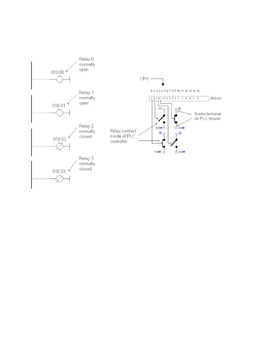
a PLC controller input and output. The easiest way to explain them is in the example of a relay.
Normally open contacts would represent relay contacts that would perform a connection upon receipt of a signal.
Unlike open contacts, with normally closed contacts signal will interrupt a contact, or turn a relay off. Previous
picture shows what this looks like in practice. First two relays are defined as normally open , and the other two as
normally closed. All relays react to a signal! First relay (00) has a signal and closes its contacts. Second relay (01)
does not have a signal and remains opened. Third relay (02) has a signal and opens its contacts considering it is
defined as a closed contact. Fourth relay (03) does not have a signal and remains closed because it is so defined.
Concepts "normally open" and "normally closed" can also refer to inputs of a PLC controller. Let's use a key as an
example of an input to a PLC controller. Input where a key is connected can be defined as an input with open or
closed contacts. If it is defined as an input with normally open contact, pushing a key will set off an instruction
found after the condition. In this case it will be an activation of a relay 00.
If input is defined as an input with normally closed contact, pushing the key will interrupt instruction found after
the condition. In this case, this will cause deactivation of relay 00 (relay is active until the key is pressed). You can
see in picture below how keys are connected, and view the relay diagrams in both cases.
http://www.mikroelektronika.co.yu/english/product/books/PLCbook/chapter5/chapter5.htm (3 sur 5)05/11/2004 02:40:24
Chapter5
Normally open/closed conditions differ in a ladder diagram by a diagonal line across a symbol. What determines an
execution condition for instruction is a bit status marked beneath each condition on instruction line. Normally open
condition is ON if its operand bit has ON status, or its status is OFF if that is the status of its operand bit. Normally
closed condition is ON when its operand bit is OFF, or it has OFF status when the status of its operand bit is ON.
When programming with a ladder diagram, logical combination of ON and OFF conditions set before the instruction
determines the eventual condition under which the instruction will be, or will not be executed. This condition, which
can have only ON or OFF values is called instruction execution condition. Operand assigned to any instruction in a
relay diagram can be any bit from IR, SR, HR, AR, LR or TC sector. This means that conditions in a relay diagram
can be determined by a status of I/O bits, or of flags, operational bits, timers/counters, etc.
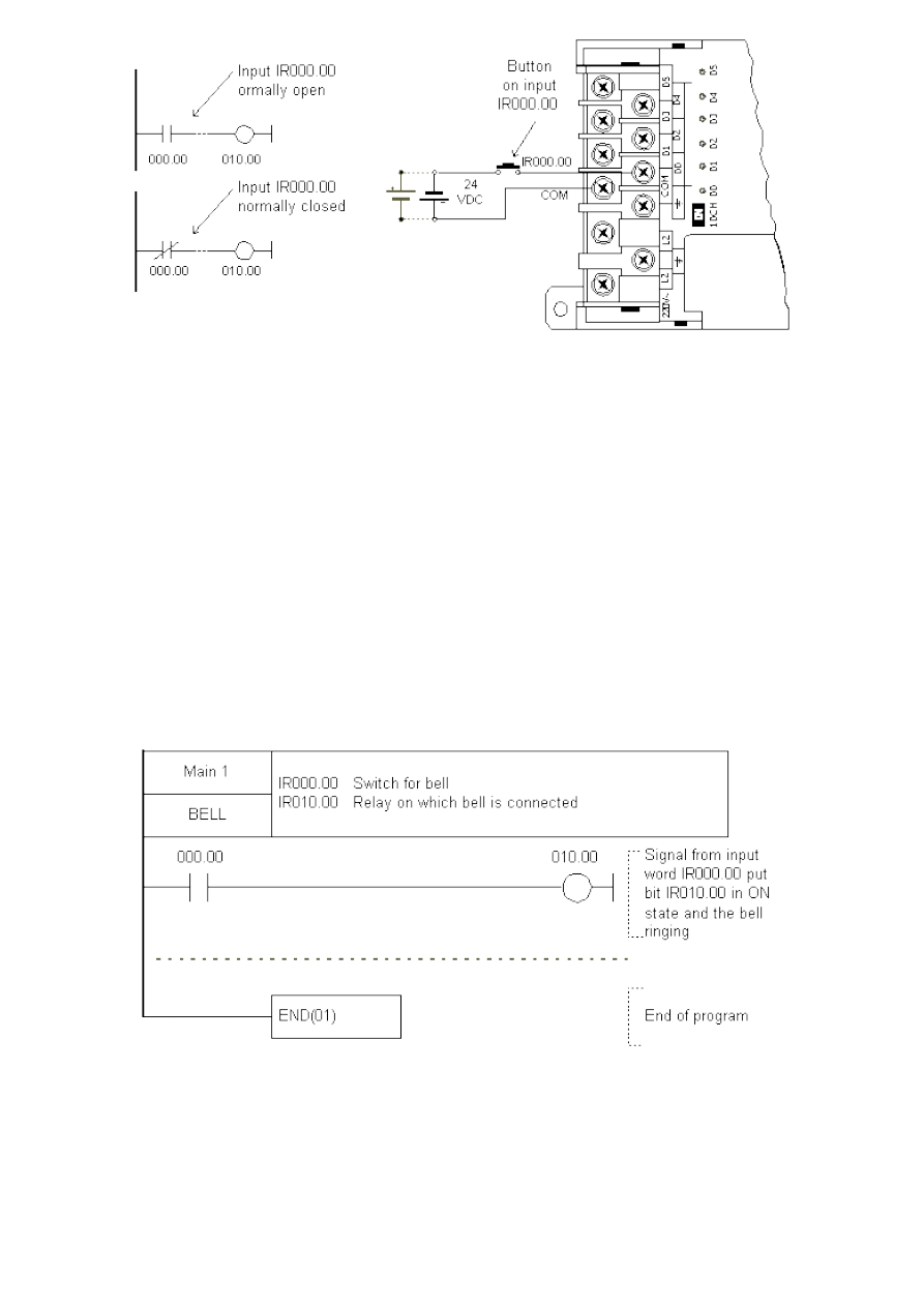
5.3 Brief example
Example below represents a basic program. Example consists of one input device and one output device linked to
the PLC controller output. Key is an input device, and a bell is an output supplied through a relay 00 contact at the
PLC controller output. Input 000.00 represents a condition in executing an instruction over 010.00 bit. Pushing the
key sets off a 000.00 bit and satisfies a condition for activation of a 010.00 bit which in turn activates the bell. For
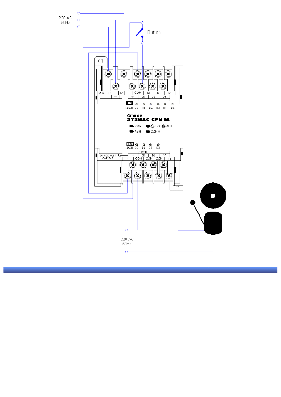
correct program function another line of program is needed with END instruction, and this ends the program.
The following picture depicts the connection scheme for this example.
http://www.mikroelektronika.co.yu/english/product/books/PLCbook/chapter5/chapter5.htm (4 sur 5)05/11/2004 02:40:24
Chapter5
© Copyright 2003 mikroElektronika. A l l R i g h t s R e s e r v e d . F o r a n y c o m m e n t s c o n t a c t
.
http://www.mikroelektronika.co.yu/english/product/books/PLCbook/chapter5/chapter5.htm (5 sur 5)05/11/2004 02:40:24
Chapter6
Introduction to PLC controllers
on-line
FREE
!
Index
Development systems
Contact us
CHAPTER 6
SYSWIN program for programming a PLC controller
Introduction
6.1 Connecting a PLC controller with a PC computer
6.2 SYSWIN program installation
6.3 Writing your first program
6.4 Saving a project
6.5 Program transfer to PLC controller
6.6 Testing program function
6.7 Interpretation of "Tools" icons
6.8 PLC controller working modes
6.9 Run mode
6.10 Monitor mode
6.11 Program-Stop mode
6.12 Program execution and monitoring
6.13 Impact on the program during monitoring
6.14 Graphic representation of dimension changes in a program
Introduction
SYSWIN is a software designed for OMRON programmable controllers class C and CV. It is designed for creating
and maintaining a program, as well as for testing PLC controller function, in off-line and controller's operational
regime.
Necessary conditions for starting SYSWIN are Microsoft Windows environment on a standard IBM or 386/486
compatible or Pentium computer, with 8MB RAM at least, and 10MB free disc space.
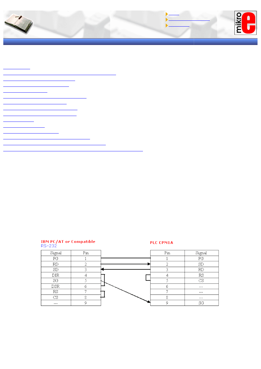
6.1 Connecting a PLC controller with a PC computer
PLC controller is linked with a PC computer through an RS-232 cable. One end of the cable is connected to a serial
PC port (9-pin or 25-pin connector), while the other end is connected to an RS-232C connector on RS232 module
of a CPM1A controller. In order to establish a connection with a PC, DIP switch on the connector must be set in
"Host" position.
6.2 SYSWIN program installation
Instruction package for CPM1A is covered by three SYSWIN installation diskettes. It can be installed in Windows
3.1, 3.11, 95, 98 or NT 4.0. In order to start the installation you need to select RUN option from a START menu.
http://www.mikroelektronika.co.yu/english/product/books/PLCbook/chapter6/chapter6.htm (1 sur 11)05/11/2004 02:41:04
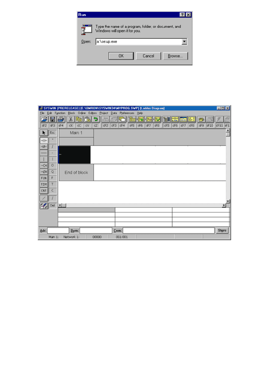
Chapter6
A window will come up like the one below where you need to write in the file command "setup.exe". Mentioned file
can be found in the installation directory of Syswin program. Following a brief installation procedure you will get a
program group Syswin 3.4.
Double-click on Syswin icon starts a Syswin program which opens as in the following picture.
6.3 Writing your first program
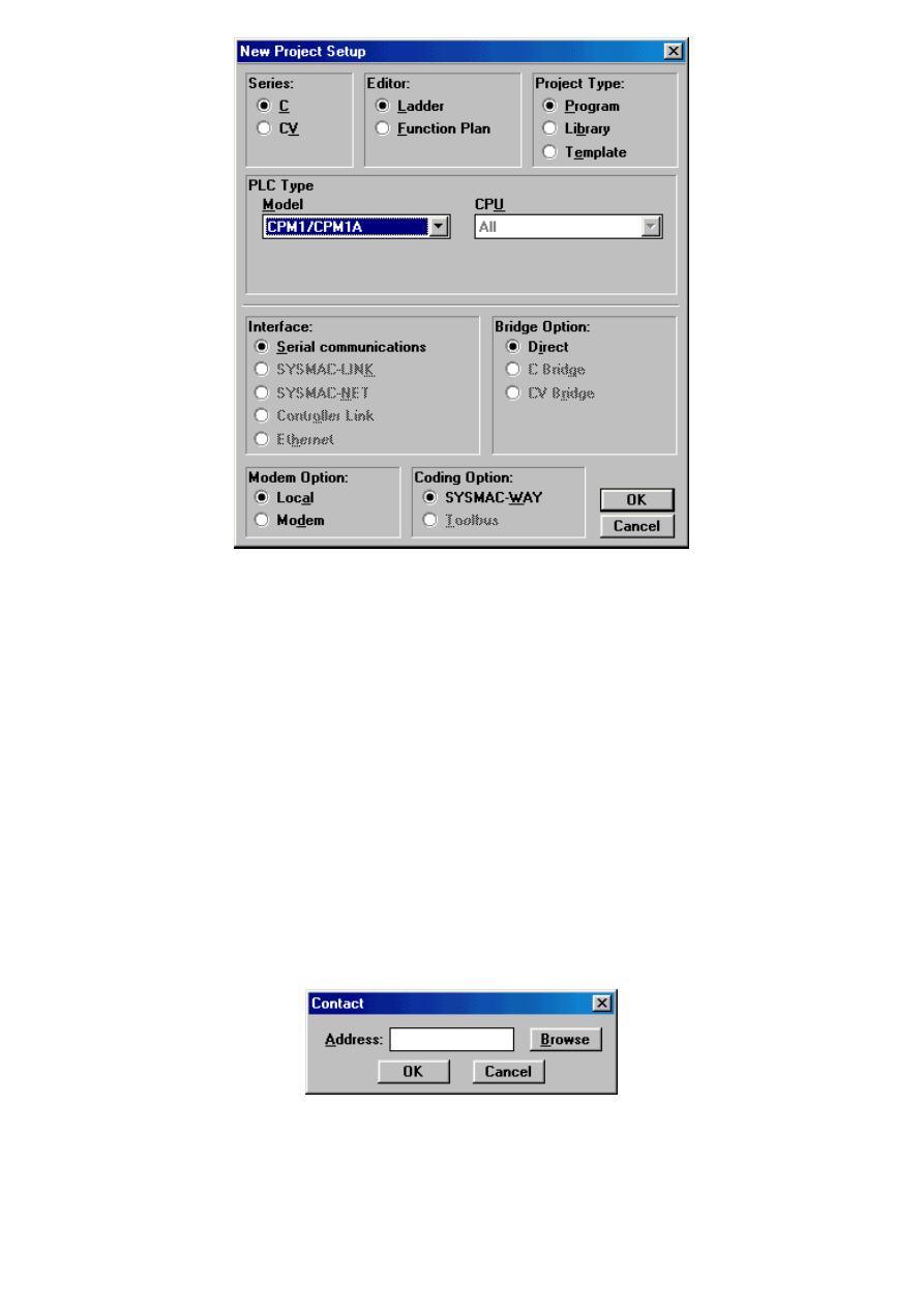
Writing a program begins with New Project option from a File menu. In a message window that appears you need
to select options as in picture below.
http://www.mikroelektronika.co.yu/english/product/books/PLCbook/chapter6/chapter6.htm (2 sur 11)05/11/2004 02:41:04
Chapter6
Select a PLC controller by clicking on OK, and a program is ready to be used. It is recommended when you begin
working that you write in a header a title of a program, author's name and inputs/outputs used. This may seem as
a waste of time, but really isn't because this habit of writing comments will pay off in the future.
Program written here is just a basic program made for learning Syswin. Program can detect when a key has been
pressed and can activate a relay at the PLC controller output. As long as the key is pressed down, a relay is active.
Operation of a relay and a key can be followed via LED diodes on PLC controller housing. Writing a program begins
with a click on the first icon to the left, recognized by two vertical lines. Icon beneath this one is similar to the first
but for a slash. These two icons correspond with concepts normally open and normally closed contact which all
instruction lines start with. You can select an option with an open contact by clicking on the first icon. When you
click on the black rectangle to the right, a small window will appear where you need to write in the address of a bit
a contact relates to.
It is very important to use addresses in a regular way when programming with SYSWIN. Addresses can have two
parts, first refers to the word address, and the second to bit address in that word (both numbers must be
separated by a period). For example, if address 200 is used, SYSWIN will interpret this as 2.00, and a zero bit
whose word address is 2 will be called for. If you wish to access word 200 or its zero bit, you must use a call
20000, or better even 200.00. In this example address 000.00 is assigned for input address (key). This address
represents a zero bit for word 000 from memory region IR. Simply said, it is an input screw terminal designated as
00 input. By connecting a key to it, and to one of the COMM terminal screws, a needed connection between PLC
controller and keys is established.
Address dialogue box for a bit that contact refers to
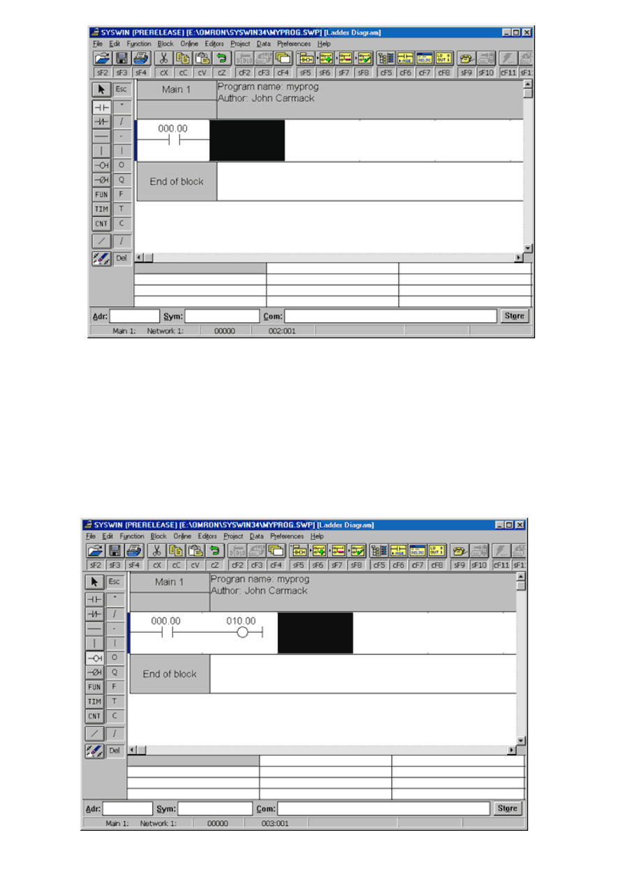
When you have written in 000.00, select OK, and first segment of the program will come up. Bit address will
appear above the symbol with two vertical lines which refers to this bit, and a black rectangle will move one space
to the right.
http://www.mikroelektronika.co.yu/english/product/books/PLCbook/chapter6/chapter6.htm (3 sur 11)05/11/2004 02:41:04
Chapter6
First element of a program myprog.swp
First instructions up to the bus bar are called conditions because their execution activates instructions found to the
right of the condition instructions. When a condition is entered, you also need to enter a corresponding instruction
that is set off by an execution of the condition. In this example it is a relay controlled by a 00 bit in a word 010 of
memory region IR. Output instructions are represented by a circle, or a circle and a line if we are dealing with a
normally closed contact. By clicking on the icon with a circle, you select an output option with normally open
contacts. Click on a black rectangle, and a contact window will come up where you need to write in the address for
the output bit 010.00. Output of the IR region is found at address IR010, and first four bits of this word represent a
relay within a PLC controller (if we are talking about a model CPM1A with relay outputs). Program done so far looks
as in picture below.
http://www.mikroelektronika.co.yu/english/product/books/PLCbook/chapter6/chapter6.htm (4 sur 11)05/11/2004 02:41:04
Chapter6
Second element of myprog.swp program
The basic functional entirety of some program is Network. Program consists of several networks found one below
the other. Operations with these are found in Block option of the menu. Of all options, two basic ones, Insert
network and Delete network are used the most. Other makers for PLC controllers use different concepts such as
Rung instead of the term Network. Simply said, we are talking about a PLC program sequence which has one or
more executing instructions, and along with END instruction can make up one correct PLC program. As the first
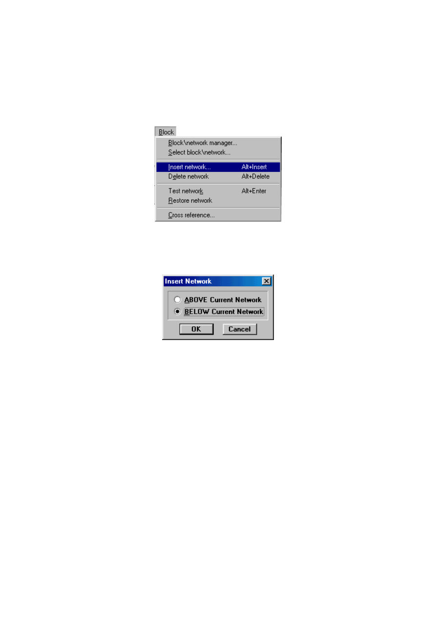
network in a program is already in use, the next one has to be added. Adding a Network is done with Insert
network command from a Block menu.
When selecting this option, a small window appears where you need to select whether a new network will appear
above or below the existing one.
In our case you should choose the second option and click on OK. Following this, a new network appears as in
picture below.
http://www.mikroelektronika.co.yu/english/product/books/PLCbook/chapter6/chapter6.htm (5 sur 11)05/11/2004 02:41:04
Chapter6
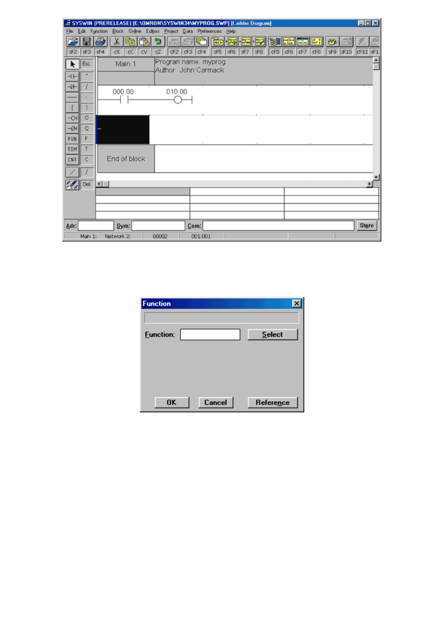
Last network in every program must contain END instruction. Since this is a simple example, second network is
also the last. End instruction is found among the functions. In order to come to it, you need to click on FUN icon
following which a window as in picture below will come up.
Selecting a function by clicking on FUN icon.
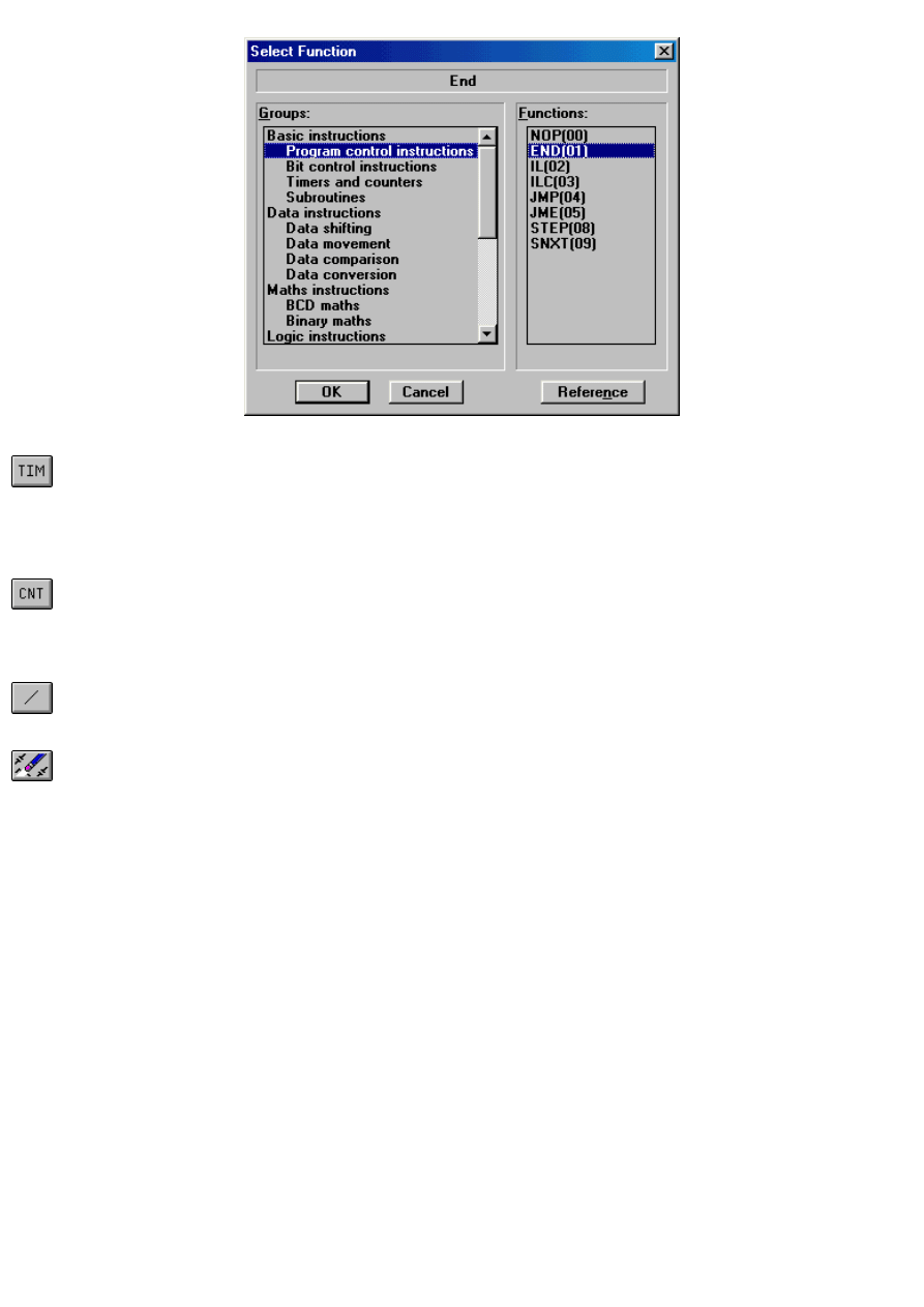
END instruction can be obtained either by writing in "END" in newly obtained window or by clicking on Select which
gives all PLC controller instructions sorted by the regions as in the following picture.
http://www.mikroelektronika.co.yu/english/product/books/PLCbook/chapter6/chapter6.htm (6 sur 11)05/11/2004 02:41:04

Chapter6
Selecting END instruction from a set of instructions sorted in regions.
By entering the END instruction your writing of a program is finished. Finished program looks as in the following
picture.
Finished myprog.swp program
6.4 Saving a project
Since you've finished writing a program, you need to save a project. Select Save Project option from a File menu,
and write in the file name in a message window (myprog.swp in this case). After you click on OK, project will be
saved. You can access SYSWIN file contents only from SYSWIN; file type is identified by extension:
Project.swp - SYSWIN program
Project.swl- SYSWIN library
http://www.mikroelektronika.co.yu/english/product/books/PLCbook/chapter6/chapter6.htm (7 sur 11)05/11/2004 02:41:04
Chapter6
Project.swt - SYSWIN pattern
Project.swb - SYSWIN back-up file
Project.prg - PMD program
6.5 Program transfer to PLC controller
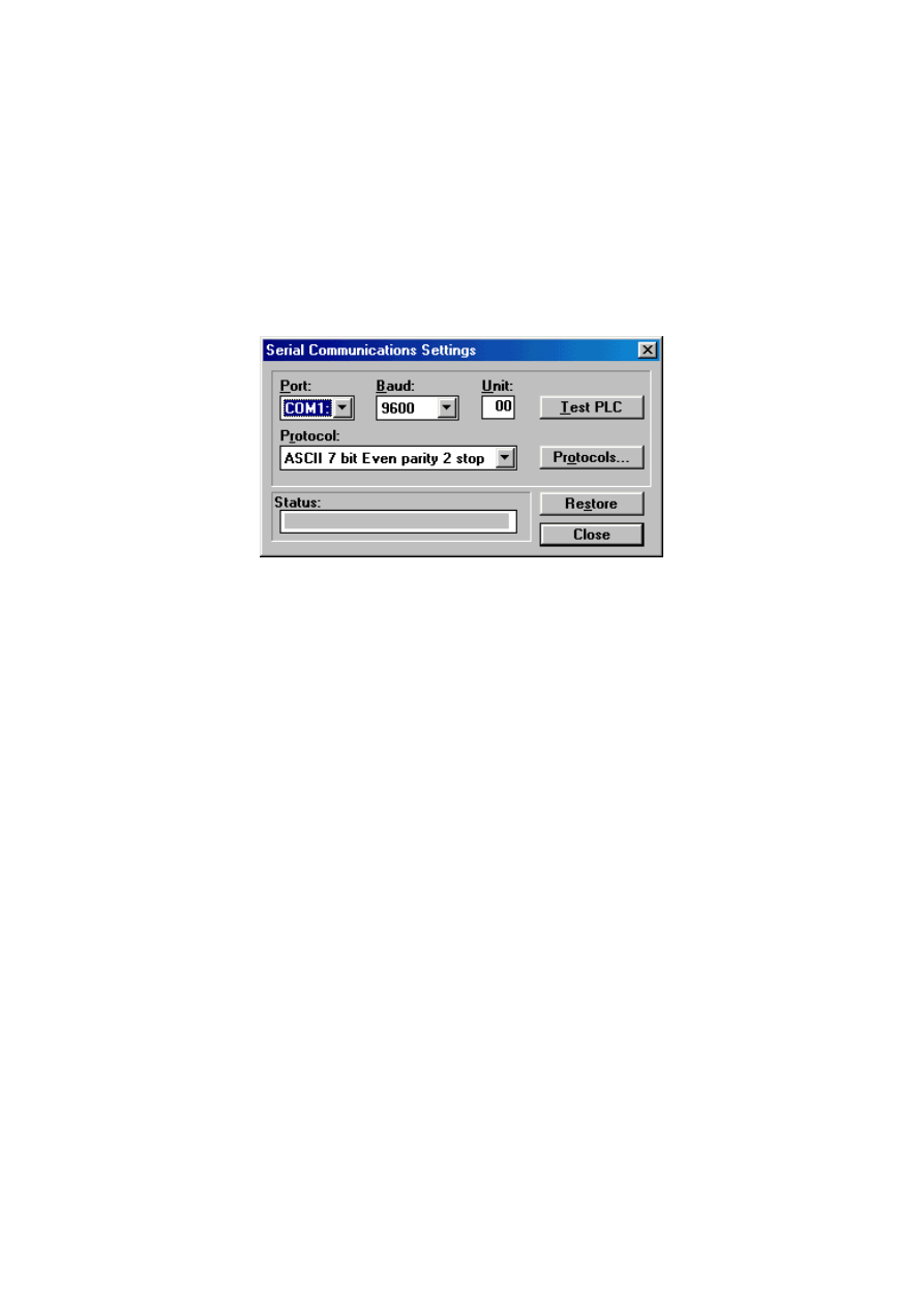
First you need to check whether PLC is connected with a PC correctly, and you'll do this by checking physical
connection through a serial cable. Following this you need to select a Communication option from Project menu in
order to set parameters for serial communication. Of all the parameters, the most important one to be selected is a
serial port of a computer that PLC is connected to. Default settings for CPM1A are: COM1, 9600 Baud, Unit 00,
protocol ASCII 7 bit Even Parity 2 stop and they need to be left so. To check how communication functions, you
can click on Test PLC to test link with a PLC controller.
When a connection has been established, program transfer begins with a click on download from Online menu.
Select expansion function or memory allocation. Before you program a PLC, it's good to erase program's memory
contents. Finally, after a successful program transfer to a PLC, a message window will come up to inform us of this.
6.6 Testing program function
Program check option from a Project menu allows testing of program function. Message that appears following a
command has several options that can be selected before you run a test. Once these options have been selected,
click on Execute, and a report on testing and errors will be displayed. You can further check for errors, and there is
also a 'Go to Network' command which transfers you to a segment where the error was found.
SYSWIN has classic editorial capabilities, such as Edit/Find or Edit/Replace commands. Searching through a
program for assigned values or symbols is quick and offers a large number of optional filters. We can search
through an entire program or its segments, and this is defined with option call. Also, there are possibilities for
defining a search path, as well as for different actions when looking for a desired element.
Beside this, SYSWIN provides various advantages in situations where we need permanent archiving of user
program. It is especially important to periodically print projects that are made quick and easy by SYSWIN. Projects
can be printed in many different formats, and printing can include specific sections of a project.
6.7 Meaning of "Tools" icons
SYSWIN has several types of editors among whom a relay diagram also known as relay editor, or first editor that
awaits us upon starting a SYSWIN program is the most frequently used editor.
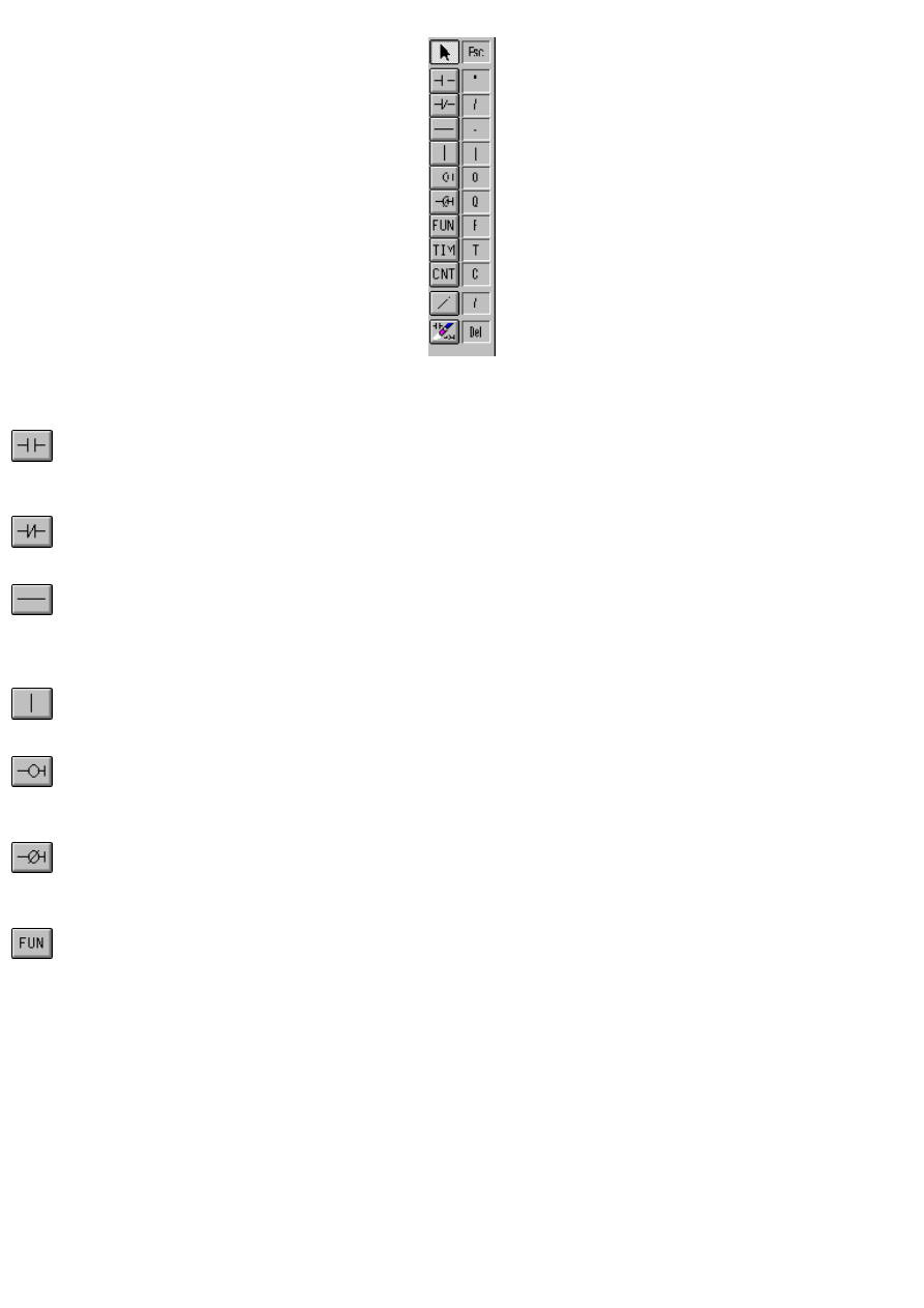
First we need to explain tools palette (Drawing Tools) and the meaning of each icon. Aside through the usual
mouse click, you can access the specific elements of this palette from a keyboard. You'll find a corresponding key
of the keyboard by each icon, and you can accomplish the same action with it as you would using a mouse.
http://www.mikroelektronika.co.yu/english/product/books/PLCbook/chapter6/chapter6.htm (8 sur 11)05/11/2004 02:41:04
Chapter6
By clicking on the icon, we have selected a desired tool, and with a click on network section this symbol will be
stored in a program. Explanation for each of the icons is given as follows:
Open contact icon. By clicking on this icon (or using a key '"') we enter an open contact into Network. We need to
position the element we have entered at a specified place (black space). Following this, a message window where
data can be entered (open contact address-number of words, bit position) is activated automatically.
Closed contact icon. By clicking on this icon (or '/' on keyboard) we enter a closed contact or inverted condition
into network.
Horizontal line. By clicking on this icon (or using '-' on a keyboard), horizontal line is lengthened out from left to
right. SYSWIN, however, retains a right to make drawn lines optimal in terms of length, or to point out possible
errors. This option is used when you need to add another condition before an instruction contingent upon this
condition, or when something simply can not fit.
Vertical line. With a click on this icon, or use of '?', we draw vertical lines from top to bottom. This option is
necessary to realize parallel connections between contacts.
Output instruction. This represents an instruction that is executed if condition instruction preceding it is executed.
With the help of this instruction we advance a result of logical expression with output variables (bits). We can
arrive to this instruction with the help of keyboard ('O' key).
Inverted output instruction (shortcut-key 'Q'). Similarly to the previous case, with this executing instruction we
advance a result of logical expression to an output bit, and the only difference is that this bit is turned on if a
condition is not executed and vice versa.
PLC functions (shortcut-key 'F'). Click on this icon accomplishes possibility of installment of complex PLC
instructions into a program. Window that appears following a click on the icon contains all instructions sorted by
sections. Some of these instructions are given separately as icons, and some can be accessed only through this
option. One such instruction is END instruction which is used in each program. Window that comes up is displayed
in the following picture.
http://www.mikroelektronika.co.yu/english/product/books/PLCbook/chapter6/chapter6.htm (9 sur 11)05/11/2004 02:41:04
Chapter6
When this window pops up, select an instruction and click on OK.
Click on this icon (or using 'T' key) will give you an option to enter a timer into the program. Using a mouse, click
on the bright area of the monitor, and a message window comes up where you can enter needed information
relating to a timer (timer designation and duration in milliseconds). This way, we get a classic timer or timer with a
delay when turned on. If some other version of a timer is needed, preceding FUN icon should be used, and option
Timers and counters (see picture above) selected.
Counter icon. Click on this icon (or 'C' key), and this will install a classic counter into a PLC program. Prior to this
we enter needed information in message window: designation of the counter (CNT001 for instance) and counter
value. Change of counter status (decrementing by 1) is done when an input signal (CP) changes from OFF to ON
status.
With this icon we can invert previously entered contact, output or input. Inversion is done so that we first click on
this icon, and then on a variable whose inversion we wish to perform.
Erase icon. Click on this icon and a shaded area of network erases the shaded part of the program.
Mouse plays an important part in the SYSWIN program. Each double-click on any PLC instruction results in a
corresponding editor where necessary changes can be entered. This principle is accordingly installed into SYSWIN,
so double-click on block or network heading (BLOCK HEADER BAR or NETWORK HEADER BAR) gives the same
results.
6.8 PLC controller working modes
There are several ways to find out the present working mode, for example from an Online Mode menu or its display
in a Toolbar. This option is accessible if communication was successfully established with a PLC controller.
If we choose a mode that differs from a present one, change of mode will be momentary. In order to avoid an
accidental change of PLC controller mode, there is an option that obliges a computer to ask a question before each
mode change, whether that is the option a user really wants (this option is included as default). PLC controller has
three modes in class C, MONITOR, RUN and PROGRAM/STOP mode.
6.9 RUN MODE
This PLC mode enables program to be executed as basic operation. It is used in final testing, after a program has
been tested in detail, and errors have been eliminated. SYSWIN can not change memory contents of PLC controller
in this mode, neither is the change of a program being executed possible. Of course, when program is finished and
tested, PLC begins its new life in command closet, being first set to RUN mode.
6.10 Monitor mode
In this mode, program execution is possible, as well as editing and monitoring during operation. This is the most
http://www.mikroelektronika.co.yu/english/product/books/PLCbook/chapter6/chapter6.htm (10 sur 11)05/11/2004 02:41:04

Chapter6
frequently used mode in program development. When this mode has been selected, controller has an obligation to
supply a PC with information which relates to program itself, or more precisely to status of variables in the
program. If we additionally confirm Monitoring option from an Online menu, we can follow current values of
variables on the monitor itself, in real time.
All changes in inputs and outputs can be viewed on the monitor, and status of variables and program locations
used in the program are registered and memorized.
6.11 Program-Stop mode
Choosing this mode simply stops a PLC controller if PLC was in RUN or MONITOR mode. It is used for data and
program transfer to PLC controller.
6.12 Program execution and monitoring
Program transferred from a PC to a PLC starts executing at the moment when you move from a Stop/Program
mode to a Monitor or Run mode. When Monitoring function starts executing, some sections of the monitor will be
shaded (see picture above), and this way you can follow program execution. Monitoring is active during editing of
some program segment, and is stopped at the moment when a changed section of the program is transferred into
a PLC controller.
6.13 Impact on the program during monitoring
During monitoring, you can use the right button on the mouse to call up a menu of some elements of ladder
diagram. Menu that appears when we click on location where address of some bit is positioned, contains the
following elements:
Force Set - used for permanent forced set up of bit status to ON
Force Reset - used for permanent forced set up of bit status to OFF
Cancel - cancels out the forced status
Set (1) - used for a brief change of bit status from OFF to ON status
Reset (0) - used for a brief change of bit status from ON to OFF status
Cancel All - cancels out forced status of all bits
With the help of these options, status of bits can be changed, word contents in controller memory can also be
changed, and all or some of the earlier forced settings can be cancelled out. The concept of forcing entails forced
set up of some input/output to ON or OFF status for program reevaluation. At the moment when PLC leaves
monitoring regime, data on forced bits and words is lost. Simultaneous forcing and evaluation of contents of a
greater number of dimensions, and Data Set Bar is used for this, usually found at the bottom of the monitor (see
previous picture). Editing as well as defining an area in Data Set Bar is accomplished with a double click following
which a corresponding message window appears, and we write here address for the bit whose status we are
following.
6.14 Graphic representation of dimension changes in a program
SYSWIN allows graphic representation of dimensions with time as abscissa. When a monitoring mode is in use,
monitor display changes through time, showing changes in values of monitored dimensions. Monitor refreshment is
done after a reception of each sample where sample intervals are 0,1-65.5 seconds. Graphics saved in this way
can be stored for later analysis as a file, or read in an already saved file.
Procedure for starting graphic monitoring is following:
- from Editors menu select Time chart monitoring option
- from a new tools palette select Trace Configure (pictured as a key).
- Fill out message box Configure Time Chart Monitor (see next picture)
- From Online menu choose Tracing.
With Trace/Configure command adjust parameters for monitoring. Necessary parameters are Trigger or an event
where saving will begin, sampling period and bits and/or words whose values we are monitoring. Mapping of a time
diagram for dimensions previously specified begins after the last command.
Quitting is done with a click on a black square icon, and restarting is performed by clicking on an a red circle icon.
Return to the editor with a ladder diagram by clicking on Editors menu and Program editor submenu.
© Copyright 2003 mikroElektronika. A l l R i g h t s R e s e r v e d . F o r a n y c o m m e n t s c o n t a c t
.
http://www.mikroelektronika.co.yu/english/product/books/PLCbook/chapter6/chapter6.htm (11 sur 11)05/11/2004 02:41:04
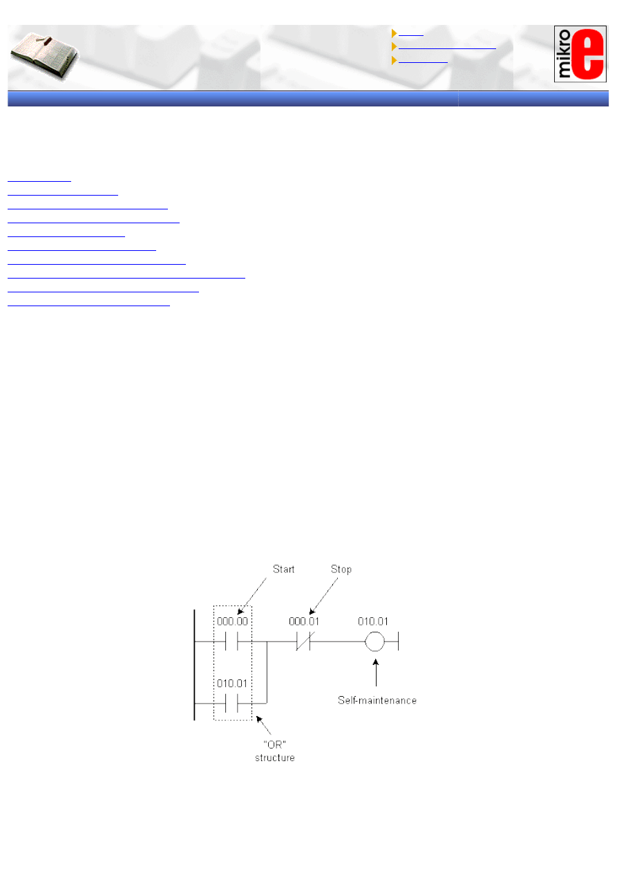
Chapter7
Introduction to PLC controllers
on-line
FREE
!
Index
Development systems
Contact us
CHAPTER 7
EXAMPLES
Introduction
7.1 Self-maintenance
7.2 Making large time intervals
7.3 Delays of ON and OFF status
7.4 Counter over 9999
7.5 Alternate ON-OFF output
7.6 Automation of parking garage
7.7 Operating a charge and discharge process
7.8 Automation of product packaging
7.9 Automation of storage door
Introduction
Programming only related examples make up the first group of examples. They are given as separate small
programs that can later be incorporated into larger ones. Second group consists of examples which can be applied
to some real problems.
7.1 Self-maintenance
Program allows input to remain at ON status even when the condition that brought it to that status stops. Example
in picture below illustrates how use of a key connected to the input IR000.00 changes IR010.01 output status to
ON. By letting the key go, output IR010.01 is not reset. This is because IR010.01 output keeps itself at status ON
through OR circuit (having IR000.00), and it stays in this status until key at input IR000.01 is pressed. Input
IR000.01 is in I connection with the output pin IR010.01 which cancels out a condition, and resets an IR010.01 bit.
Example of self-maintenance is quite frequent in specific applications. If a user was connected to IR010.01 output,
START and STOP functions could be realized from two keys (without the use of switches). Specifically, input
IR000.00 would be a START key, and IR000.01 would be a STOP key.
7.2 Making large time intervals
If it's necessary to make a bigger time interval of 999.9 seconds (9999x0.1s) two linked timers, or a timer and a
http://www.mikroelektronika.co.yu/english/product/books/PLCbook/chapter7/chapter7.htm (1 sur 5)05/11/2004 02:41:30
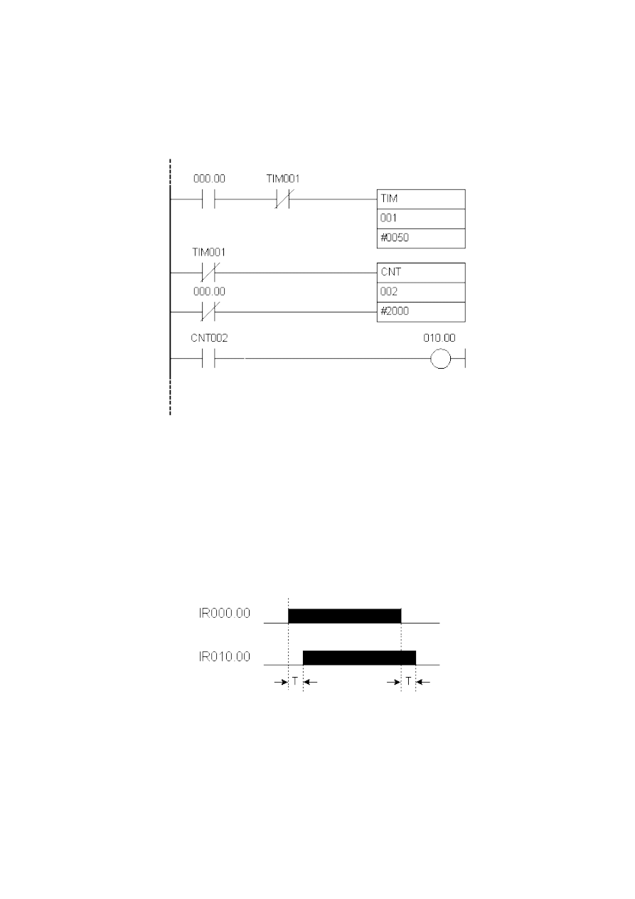
Chapter7
counter can be used as in this example. Counter is set to count to 2000, and timer is set to 5 seconds which gives
a time interval of 10.000 seconds or 2.77 hours. By executing a condition at IR000.00 input, timer begins to count.
When it reaches the limit, it sets a flag TIM001 which interrupts the link and simultaneously resets a timer. Once 5
seconds have run out, flag TIM001 changes its status to ON and executes a condition at the counter input CNT002.
When a counter numbers 2000 such changes in timer flag status, TIM001 sets its flag CNT002 which in turn
executes a condition for IR010.00 to change status to ON. Time that has elapsed from the change of IR000.00
input status to ON and a change of IR010.00 input status to ON comes to 10.000 seconds.
Ladder Diagram:
7.3 Delays of ON and OFF status
Example shows how to make output (IR010.00) delay as opposed to ?(in relation to ?? unclear meaning) input
(IR000.00). By executing a condition at IR000.00 input, timer TIM000 begins counting a set value 10 in steps of
0.1 seconds each. After one second has elapsed, it set its flag TIM000 which is a condition in changing output
status IR010.00 to ON. Thus we accomplish a delay of one second between ON status of IR000.00 input and ON
status IR010.00 input. By changing IR010.00 output status to ON, half of the condition for activation of the second
timer is executed. Second half of the timer is executed when IR000.00 input changes status to OFF (normally
closed contact). Timer TIM001 sets its flag TIM001 after one second, and interrupts a condition for keeping an
output in ON status.
Ladder Diagram:
http://www.mikroelektronika.co.yu/english/product/books/PLCbook/chapter7/chapter7.htm (2 sur 5)05/11/2004 02:41:30
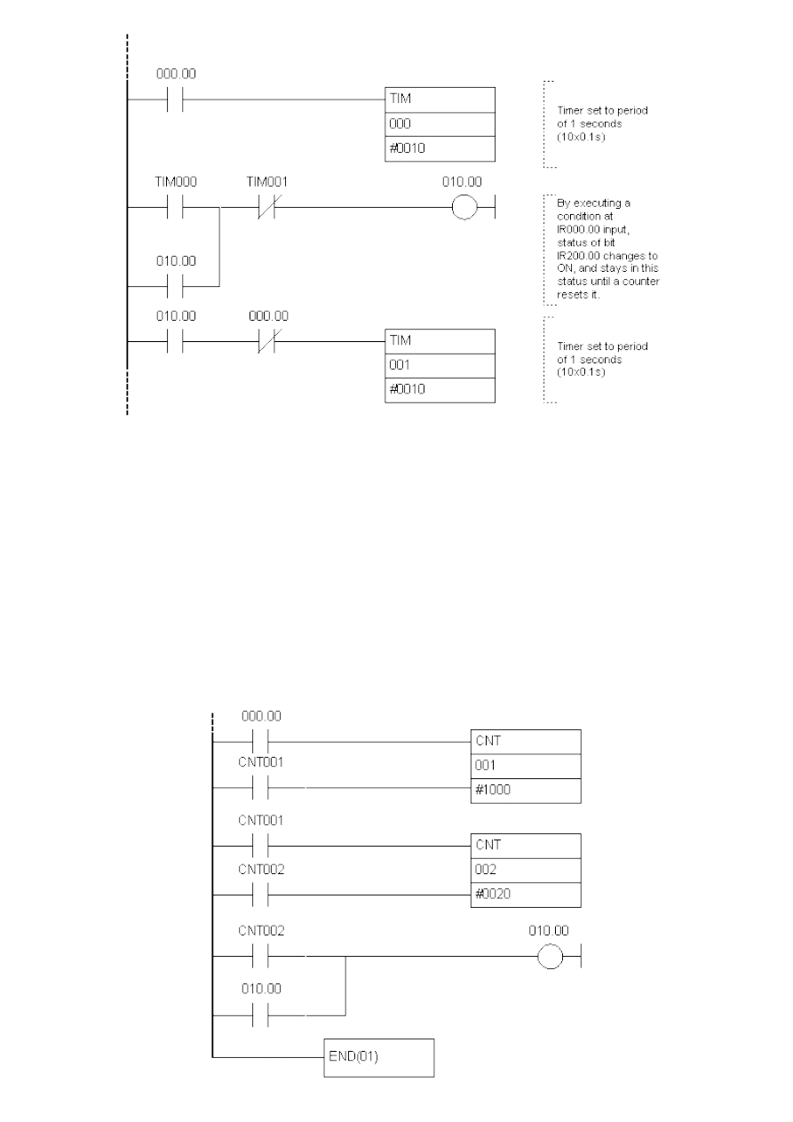
Chapter7
7.4 Counter over 9999
If you need to count over 9999 (maximum value for a counter), you can use two connected timers. First counter
counts up to certain value, and the other one counts flag status changes of the first counter. Thus you get the
possibility of counting up to a value which is a result of set values of the first and second counter. In an example at
the bottom, first counter counts up to 1000, and second up to 20 which allows you to count to 20000. By executing
a condition at IR000.00 input (line whose changes are followed is brought to it), first counter decreases its value
by one. This is repeated until counter arrives at zero when it sets its flag CNT001 and simultaneously resets itself
(is made ready for a new cycle of counting from 1000 to 0). Each setting of CNT001 influences the other counter
which sets its flag after twenty settings of the first counter's flag. By setting CNT002 flag of the second counter, a
condition is executed for an IR010.00 output to be activated and to stay in that status through self-maintenance.
Ladder Diagram:
http://www.mikroelektronika.co.yu/english/product/books/PLCbook/chapter7/chapter7.htm (3 sur 5)05/11/2004 02:41:30
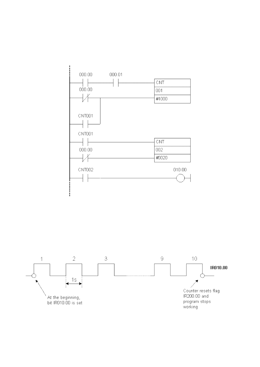
Chapter7
Same effect can be achieved with a modified program below. First change is that there is a "switch" for the whole
program, and this is IR000.00 input (program can accomplish its function only while this switch is active). Second
change is that the line whose status is followed is brought to IR000.01 input. The rest is the same as in the
previous version of the program. Counter CNT002 counts status changes of the CNT001 counter flag. When it
numbers them, it changes the status of its flag CNT002 which executes the condition for status change of IR010.00
output. This changes IR010.00 output status after 20000 changes of input IR000.01.
Ladder Diagram:
7.5 Alternate ON-OFF output
Example makes a certain number of impulses of desired duration at PLC controller IR010.00 output. Number of
impulses is given in instruction of the counter (here it is a constant #0010 or ten impulses) impulse duration in two
timer instructions. First timer defines duration of ON status, and second one duration of OFF status of IR010.00
output bit. In the example these two durations are the same, but through assigning them different parameters
they can differ so that duration of ON status can be different from duration of OFF status.
Program starts executing a condition at IR000.00 bit. Since a normally closed contact which refers to counter flag
(that isn't set ) is linked with this IR000.00 bit in "I" circuit, this status of IR200.00 bit will change to ON. Bit
IR200.00 keeps its status through self-maintenance until counter flag is not set and a condition interrupted.
http://www.mikroelektronika.co.yu/english/product/books/PLCbook/chapter7/chapter7.htm (4 sur 5)05/11/2004 02:41:30
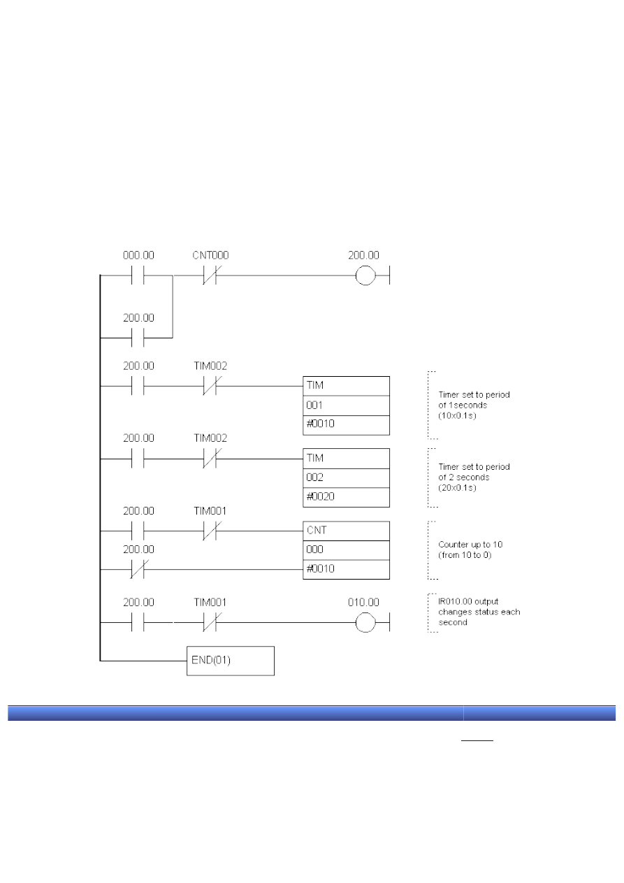
Chapter7
When an IR200.00 bit is set, timers TIM001 and TIM002 start counting a set interval number at 0.1 s ( in the
example, this number is 10 for the first timer, or 20 for the second timer, and this sets the period of one or two
seconds). With both timers, a normally closed contact which refers to TIM002 timer flag is connected with
IR200.00 bit. When this flag is set which happens every two seconds, both timers are reset. Timer TIM002 resets
timer TIM001 and itself, and this starts a new cycle.
At the start of a program, IR010.00 output bit changes status to ON and stays in this status until TIM001 flag
changes status to ON (after one second). By changing TIM001 flag status to ON, condition is broken (because it is
represented as normally closed contact) and IR010.00 bit changes status to OFF.
IR010.00 output status changes to ON again when time has run out on TIM002 timer. This resets TIM001 timer
and its flag which in turn executes a condition for status change of the IR010.00 output. Cycle is thus repeated
until a counter numbers 10 changes of TIM001 flag status. With the change of status of CNT000 counter flag, a
condition for an assisting bit IR200.00 is broken, and program stops working.
Ladder Diagram:
© Copyright 2003 mikroElektronika. A l l R i g h t s R e s e r v e d . F o r a n y c o m m e n t s c o n t a c t
.
http://www.mikroelektronika.co.yu/english/product/books/PLCbook/chapter7/chapter7.htm (5 sur 5)05/11/2004 02:41:30
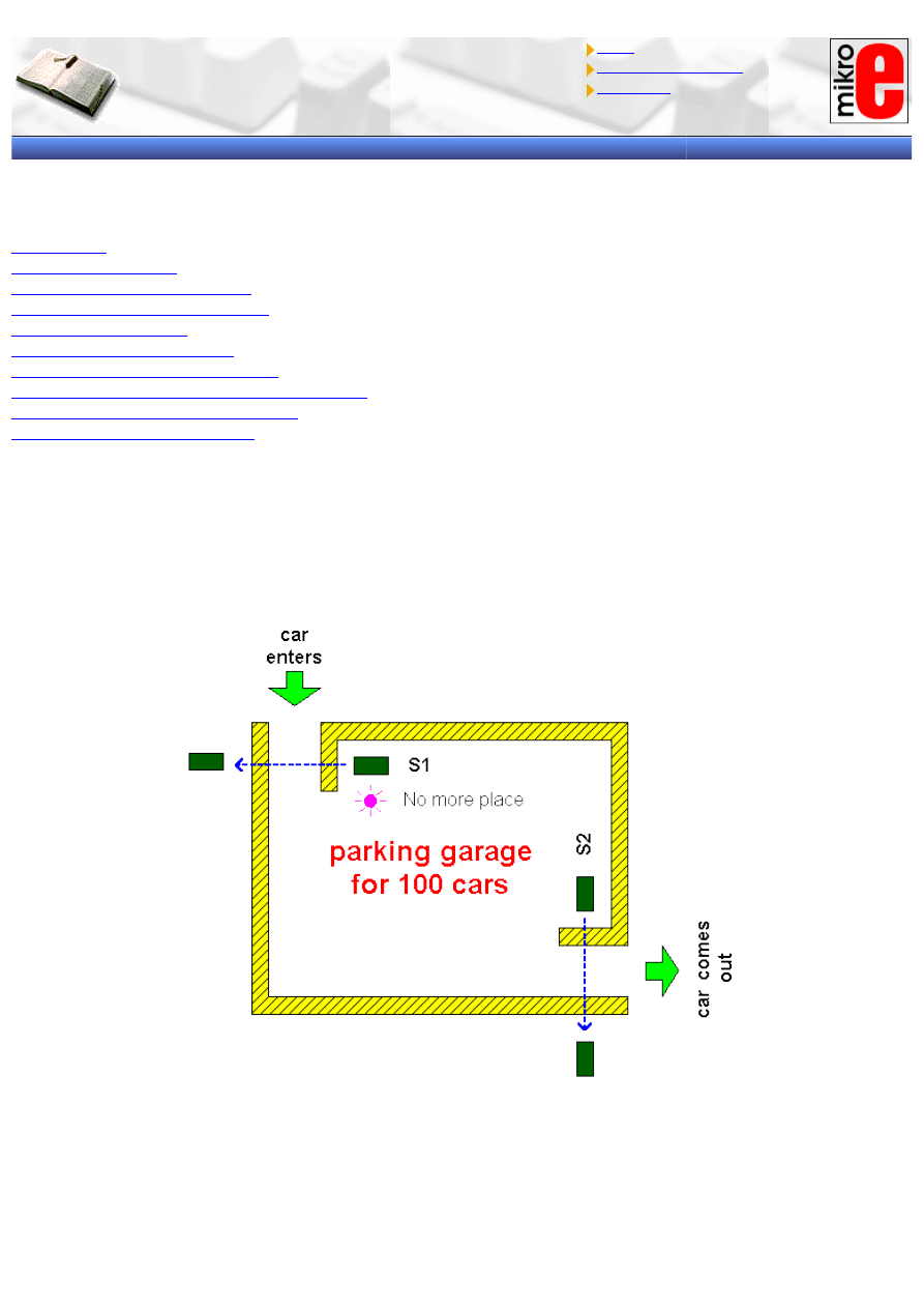
Chapter7
Introduction to PLC controllers
on-line
FREE
!
Index
Development systems
Contact us
CHAPTER 7
EXAMPLES
Introduction
7.1 Self-maintenance
7.2 Making large time intervals
7.3 Delays of ON and OFF status
7.4 Counter over 9999
7.5 Alternate ON-OFF output
7.6 Automation of parking garage
7.7 Operating a charge and discharge process
7.8 Automation of product packaging
7.9 Automation of storage door
7.6 Automation of parking garage
We are dealing with a simple system that can control 100 car at the maximum. Each time a car enters, PLC
automatically adds it to a total sum of other cars found in the garage. Each car that comes out will automatically
be taken off. When 100 cars park, a signal will turn on signalizing that a garage is full and notifying other drivers
not to enter because there is no space available.
Signal from a sensor at the garage entrance sets bit IR200.00. This bit is a condition for execution of the following
two instructions in a program. First instruction resets carry bit CY (it is always done before some other calculation
that would influence it), and the other instruction adds one to a number of cars in word HR00, and a sum total is
again stored in HR00. HR memory space is selected for storing a total number of cars because this keeps the
status even after supply stops.
Symbol "#" in addition and subtraction instructions defines decimal constant that is being added or subtracted
from a number of cars already in the garage. Condition for executing comparison instruction CPM is always
http://www.mikroelektronika.co.yu/english/product/books/PLCbook/chapter7/chapter7a.htm (1 sur 9)05/11/2004 02:42:00
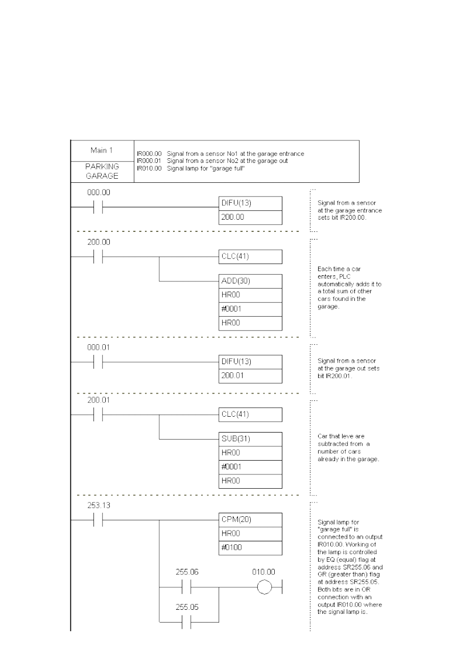
Chapter7
executed because bit SR253.13 is always set; this practically means that comparison will be done in each cycle
regardless whether car has entered or left the garage.
Signal lamp for "garage full" is connected to an output IR010.00. Working of the lamp is controlled by EQ (equal)
flag at address SR255.06 and GR (greater than) flag at address SR255.05. Both bits are in OR connection with an
output IR010.00 where the signal lamp is. This way lamp will emit light when a number of cars is greater than or
equal to 100. Number of cars in a real setting can really be greater than 100 because some untrusting driver may
decide to check whether there is any space left, and so a current number of cars can increase from a 100 to 101.
When he leaves the garage, a number of cars goes down to 100 which is how many parking spots there are in fact.
Ladder diagram:
http://www.mikroelektronika.co.yu/english/product/books/PLCbook/chapter7/chapter7a.htm (2 sur 9)05/11/2004 02:42:00
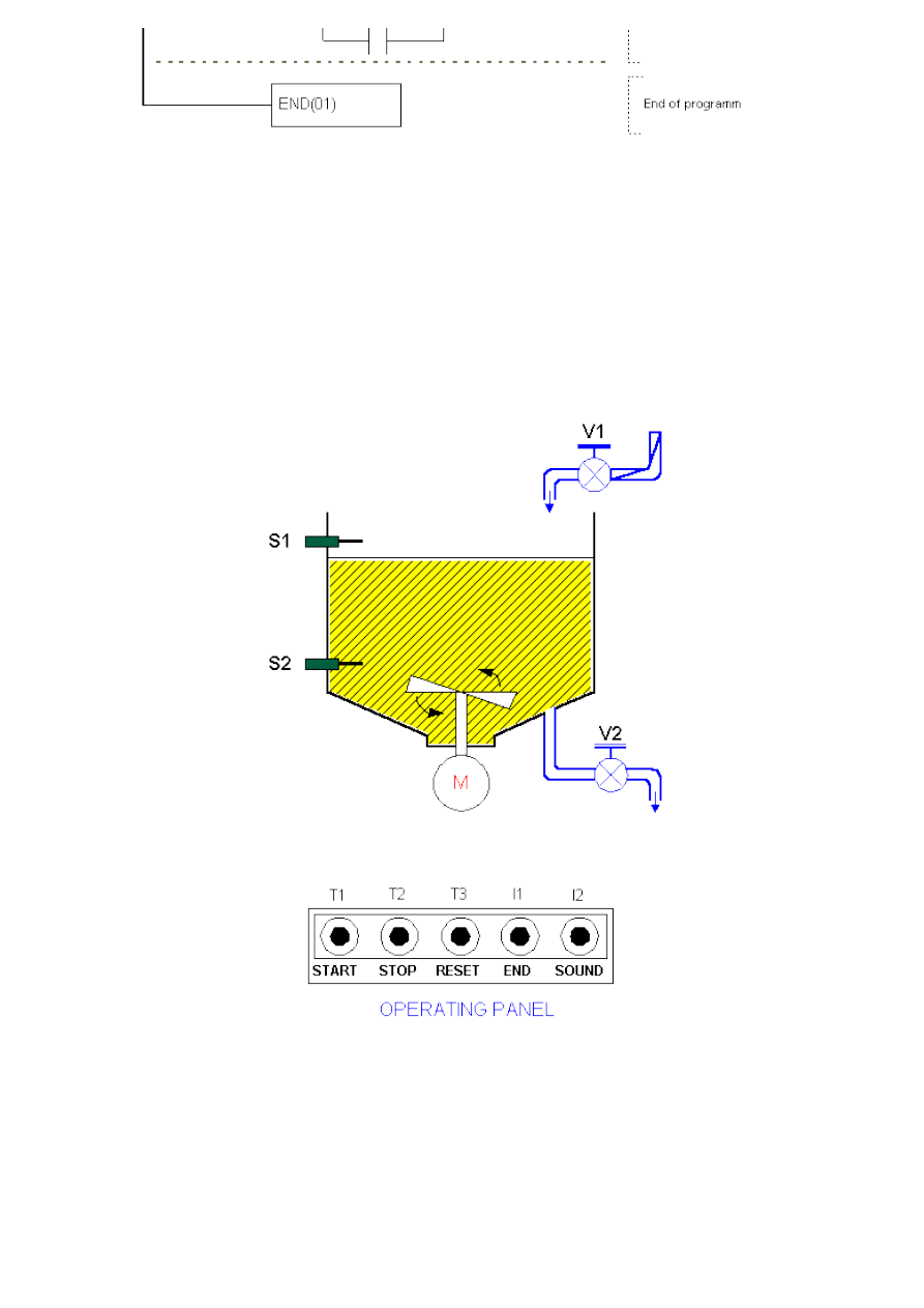
Chapter7
7.7 Operating a charge and discharge process
Charge and discharge of a reservoir is a common process in industry as well as a need for mixing two or more
substances. By using automated valves this process can be completely automated. Let's say that fluid used in the
example is water, and that a reservoir has to be filled up and emptied four times.
When you push T1 on the operating panel, valve V1 opens and a reservoir starts filling up with water. At the same
time, motor M of the mixer starts working. When the reservoir fills up, water level goes up and reaches the level
set by a sensor S1. V1 valve closes and motor of the mixer stops. Valve V2 opens then, and a reservoir starts
emptying. When water level falls below the level set by a sensor S2, valve V2 closes. By repeating the same cycle
four times, lamp that indicates end of a cycle is activated. Pressing T1 key will start a new cycle.
Both types of differentiators are used in this example. You can get an idea of what their role is from picture below.
Level S1 and S2 sensors provide information on whether fluid level goes beyond a specified value. This type of
information is not important when you wish to know whether fluid level goes up or down in a certain sequence.
Mainly, event of approaching the upper level, or a moment when fluid that fills up a reservoir goes beyond upper
level and activates sensor S1 is detected in segment 3 of a ladder diagram. Brief activation of IR200.02 output has
as a consequence a turn off of an output V1 (valve for water, prevents further flow of water but also motor
operation in the mixer). Moment prior to this (segment 5) valve V2 turns on which marks a beginning of fluid
outflow. Other two differentiators (in segments 6 and 7) have a task of registering events such as closing a valve
MV2 and drop in fluid level below allowed minimum.
http://www.mikroelektronika.co.yu/english/product/books/PLCbook/chapter7/chapter7a.htm (3 sur 9)05/11/2004 02:42:00
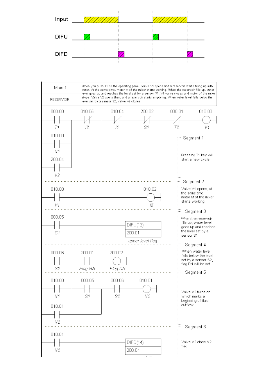
Chapter7
Ladder diagram:
http://www.mikroelektronika.co.yu/english/product/books/PLCbook/chapter7/chapter7a.htm (4 sur 9)05/11/2004 02:42:00
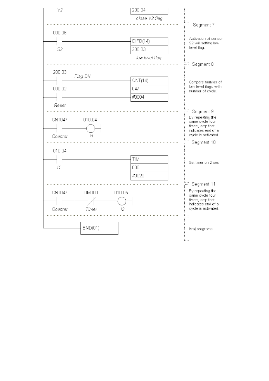
Chapter7
7.8 Automation of product packaging
Product packaging is one of the most frequent cases for automation in industry. It can be encountered with small
machines (ex. packaging grain like food products) and large systems such as machines for packaging medications.
Example we are showing here solves the classic packaging problem with few elements of automation. Small
number of needed inputs and outputs provides for the use of CPM1A PLC controller which represents simple and
economical solution.
http://www.mikroelektronika.co.yu/english/product/books/PLCbook/chapter7/chapter7a.htm (5 sur 9)05/11/2004 02:42:00
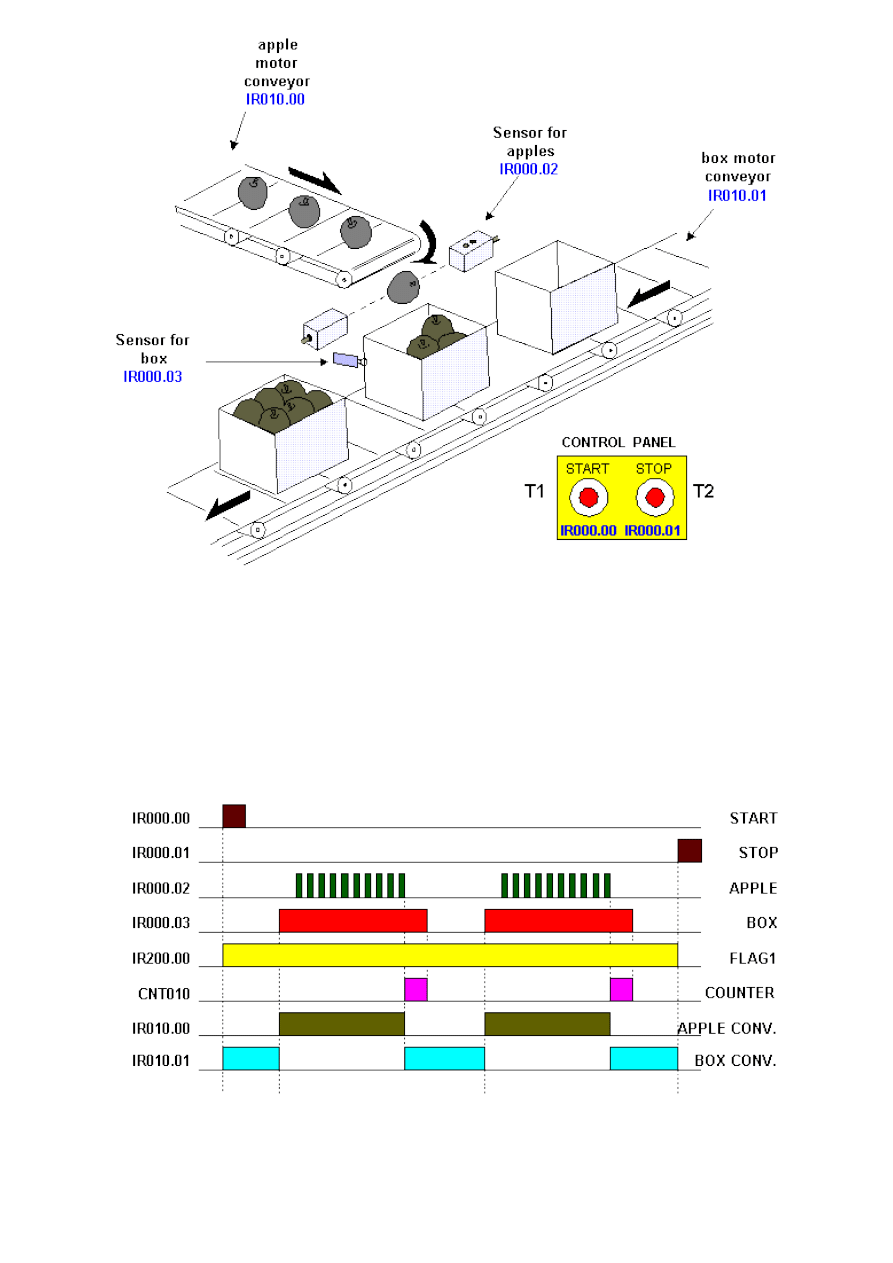
Chapter7
By pushing START key you activate Flag1 which represents an assisting flag (Segment 1) that comes up as a
condition in further program (resetting depends only on a STOP key). When started, motor of an conveyor for
boxes is activated. The conveyor takes a box up to the limit switch, and a motor stops then (Segment 4). Condition
for starting a conveyor with apples is actually a limit switch for a box. When a box is detected, a conveyor with
apples starts moving (Segment 2). Presence of the box allows counter to count 10 apples through a sensor used
for apples and to generate counter CNT010 flag which is a condition for new activation of a conveyor with boxes
(Segment 3). When the conveyor with boxes has been activated, limit switch resets counter which is again ready
to count 10 apples. Operations repeat until STOP key is pressed when condition for setting Flag1 is lost. Picture
below gives a time diagram for a packaging line signal.
Ladder diagram:
http://www.mikroelektronika.co.yu/english/product/books/PLCbook/chapter7/chapter7a.htm (6 sur 9)05/11/2004 02:42:00
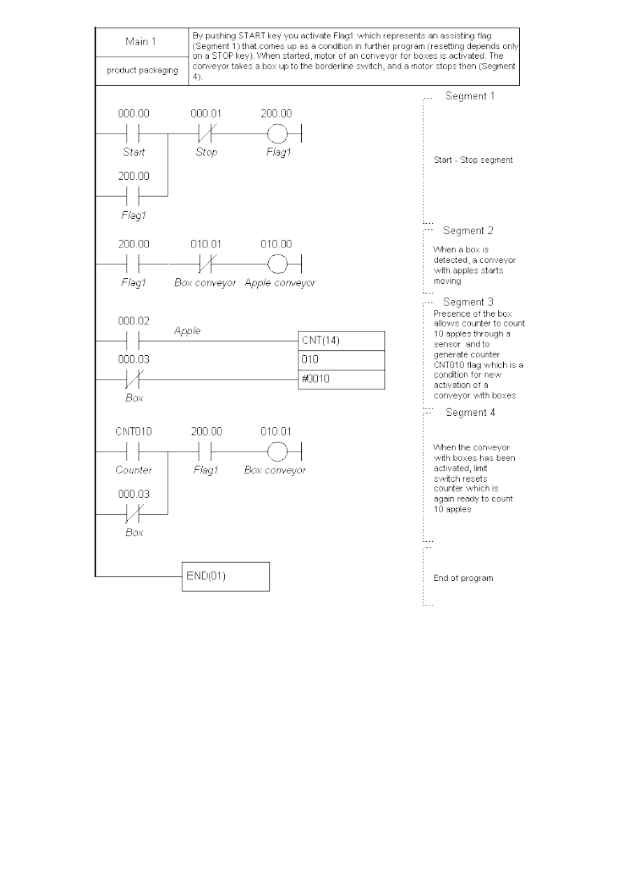
Chapter7
7.9 Automation of storage door
Storage door or any door for that matter can be automated, so that man does not have to be directly involved in
their being opened or closed. By applying one three-phased motor where you can change direction of its
movement, doors can be lifted up and lowered back down. Ultrasonic sensor is used in recognizing presence of a
vehicle by the doors, and photo-electric sensor is used to register a passing vehicle. When a vehicle approaches,
the doors move up, and when a vehicle passes through the door (a ray of light is interrupted on photo-electric
sensor) they lower down.
http://www.mikroelektronika.co.yu/english/product/books/PLCbook/chapter7/chapter7a.htm (7 sur 9)05/11/2004 02:42:00
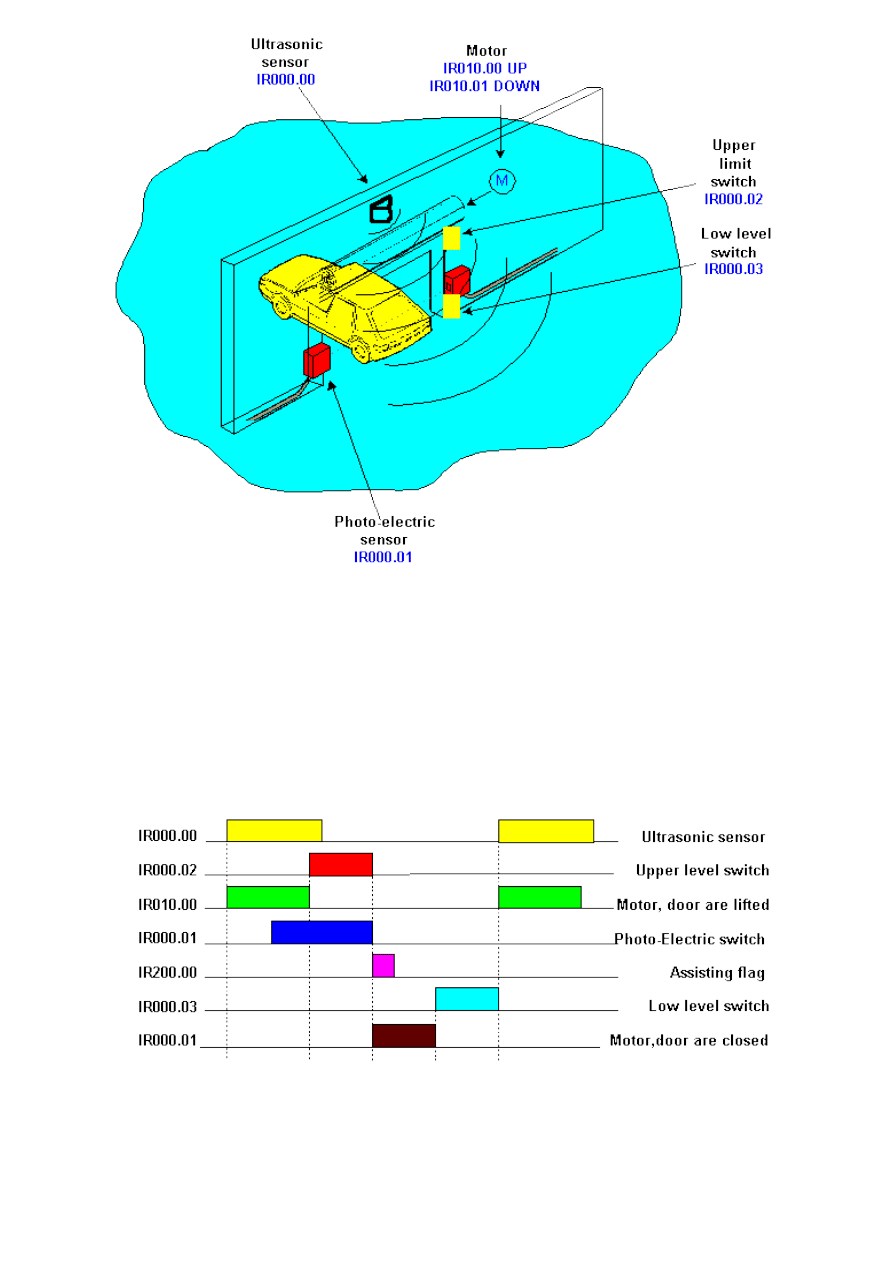
Chapter7
By setting a bit IR000.00 at the PLC controller input where ultrasonic sensor is connected, output IR010.00 (a
switch is attached to this output) is activated, so that a motor lifts the doors up. Aside from this condition, the
power source for lifting the doors must not be active (IR010.01) and the doors must not be in upper position
already (IR000.02). Condition for upper limit switch is given as normally closed, so change of its status from OFF
to ON (when doors are lifted) will end a condition for bit IR010.00 where power source for lifting the doors is
(Segment 1).
Photo-electric switch registers a vehicle that passes by, and sets flag IR200.00. DIFD instruction is used. This
instruction is activated when a condition that precedes it changes status from ON to OFF. When a vehicle passes
through a door, it interrupts a ray and bit IR000.01 status changes from ON to OFF (Segment 2).
By changing status of an assisting flag from OFF to ON a condition for lowering a door is executed (Segment 3).
Aside from this condition, it is necessary that a unit power source for lifting a door is turned off, and that door is
not in lower position already. Bit which operates this power source for lowering, IR010.01 is automatic, so doors
are lowered until they come to the bottom limit switch which is represented in a condition as normally closed. Its
status change from OFF to ON interrupts a condition of the power source for lowering doors. With oncoming new
vehicle, cycle is repeated.
http://www.mikroelektronika.co.yu/english/product/books/PLCbook/chapter7/chapter7a.htm (8 sur 9)05/11/2004 02:42:00
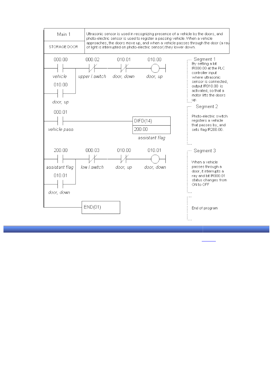
Chapter7
Ladder diagram:
© Copyright 2003 mikroElektronika. A l l R i g h t s R e s e r v e d . F o r a n y c o m m e n t s c o n t a c t
.
http://www.mikroelektronika.co.yu/english/product/books/PLCbook/chapter7/chapter7a.htm (9 sur 9)05/11/2004 02:42:00

APPENDIX A - Expanding the number of input/output lines
Introduction to PLC controllers
on-line
FREE
!
Index
Development systems
Contact us
APPENDIX A
Expanding the number of input/output lines
A.1 Differences and similarities
A.2 Marking the PLC controller
Introduction
This appendix is an answer to the question “What if more input or output lines are needed ?”. Model detailed in the
book carries the mark CPM1A-10CDR-A and is taken as an optimal for it’s price and features. Alternative models
with greater number of lines include CPM1A-20CDR-A, CPM1A-30CDR-A or CPM1A-40CDR-A. The last two can be
expanded with three additional modules with 20 extra I/O lines each, totaling 100 I/O lines as a maximum (if this
is still insufficient, maybe it is time for you to start using some of more powerful PLC controllers).
If not even the most powerful model of CPM1A family satisfies your needs, then extra modules with 20 I/O lines
are added. This form of connection reaches 100 input/outputs, which is a significant number in industrial
proportions.
A.1. Differences and similarities
Taking the other model of PLC controller from CPM1A class basically doesn’t change a thing! Everything said for
one model also applies to the other. Only thing that changes is the number of screw terminal and the number of
bits in IR area connected to that screw terminal. If model with 10 I/O lines (model described in the book) has 6
inputs on addresses IR0000 - IR0005, then the 20 I/O lines model will have 12 inputs on addresses IR0000 -
IR0011. Expanding itself should not be a problem. After taking off the cover on the right side, there is a connector
which is then connected to the expansion module via flat cable. Still, it requires skill when assigning inputs and
outputs because expansion increases the cost of the project. All the models and expansions of CPM1A class carry
additional marks defining them more precisely.
Description
Input points
Output points
Power Supply
Model Number
10 I/O points 6 points
4 point Relay
Output
100 to240 VAC,
50/60 Hz
CPM1A-10CDR-A
24 VDC
CPM1A-10CDR-D
Transistor NPN 24 VDC
CPM1A-l0CDT-D
Transistor PNP
24 VDC
CPM1A-10CDT1-D
20 I/O points
12 points
8 points
100 to 240 VAC,
50/60 Hz
CPMlA-20CDR-A
24 VDC
CPM1A-20CDR-D
Transistor NPN 24 VDC
CPM1A-20CDT-D
Transistor PNP
24 VDC
CPMlA-20CDT1-D
30 I/O points
18
points
12 points
100 to 240 VAC,
50/60 Hz
CPM1A-30CDR-A
24 VDC
CPM1A-30CDR-D
http://www.mikroelektronika.co.yu/english/product/books/PLCbook/app_a/app_a.htm (1 sur 2)05/11/2004 02:42:22
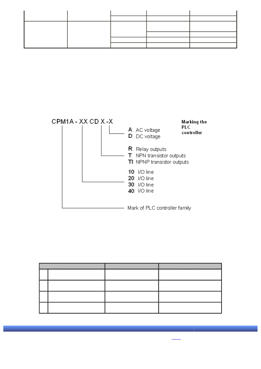
APPENDIX A - Expanding the number of input/output lines
Transistor NPN 24 VDC
CPM1A-30CDT-D
Transistor PNP
24 VDC
CPM1A-30CDT1-D
40 I/O points
24
points
16 points
100 to 240 VAC,
50/60 Hz
CPM1A-40CDR-A
24 VDC
CPM1A-40CDR-D
Transistor NPN 24 VDC
CPM1A-40CDT-D
Transistor PNP
24 VDC
CPM1A-40CDT1-D
Notice that PLC controllers with 10 and 20 I/O lines do not have an expansion port. Generally speaking, if there is
the slightest possibility for expansion in the project, PLC controller with 30 or 40 I/O lines should be used.
A.2. Marking the PLC controller
Marking the controller and the expansion module undergoes three criteria. The first is voltage, the second is the
type of input/output and the third is number of I/O lines. The picture below is self-explanatory.
A.3. Specific case
If two 20 I/O lines expansion modules and one analog module are added to 30 I/O lines model, assigned inputs/
outputs will have the addresses from the following table.
Unit
Assigned input bits
Assigned output bits
1 Central processing unit
(CPM2A-30CDX-X)
IR 00000-IR 00011
and IR 00100-IR 00105
IR 01000-IR 01007 and IR
01100-IR 01103
2 Unit for I/O expansion
(CPM1A-20EDxxx)
IR 00200-IR 02011
IR 01200-IR 01207
3 Analog I/O unit (CPM1A-
MAD01)
IR 00300-IR 03015
and IR 00400-IR 00415
IR 01300-IR 01315
4 Unit for I/O expansion
(CPM1A-EDxxx)
IR 00500-IR 00511
IR 01400-IR 01415
© C o p y r i g h t 2 0 0 3. m i k r o E l e k t r o n i k a. All Rights Reserved. For any comments contact
.
http://www.mikroelektronika.co.yu/english/product/books/PLCbook/app_a/app_a.htm (2 sur 2)05/11/2004 02:42:22
APPENDIX B - Detailed memory map of PLC controller
Introduction to PLC controllers
on-line
FREE
!
Index
Development systems
Contact us
APPENDIX B
Detailed memory map of PLC controller
B.1 General explanation of memory areas
Introduction
Purpose of this appendix is to explain certain memory areas in detail. As the following tables cover whole memory,
there are options left unused in this book. They should be skipped during the first reading, and used later
according to needs.
B.1 General explanation of memory areas
Memory of PLC controller consists of several areas, some of these having predefined functions.
Data area
Word(s)
Bit(s)
Function
IR area
input area
IR 000 - IR 009 (10 words)
IR 00000 - IR 00915 (160
bits)
These bits may be assigned
to an external I/O
connection. Some of these
have direct output on screw
terminal (for example,
IR000.00 - IR000.05 and
IR010.00 - IR010.03 with
CPM1A model)
output area
IR 010 - IR 019 (10 words)
IR 01000 - IR 01915 (160
bits)
working area
IR 200 - IR 231 (32 words)
IR 20000 - IR 23115 (512
bits)
Working bits that can be used
freely in the program. They
are commonly used as swap
bits
SR area
SR 232 - SR 255 (24 words)
SR23200 - SR25515 (384
bits)
Special functions, such as
flags and control bits
TR area
---
TR 0 - TR 7 (8 bits)
Temporary storage of ON/
OFF states when jump takes
place
HR area
HR 00 - HR 19 (20 words)
HR0000 - HR1915 (320 bits) Data storage; these keep
their states when power is off
AR area
AR 00 - AR 15 (16 words)
AR0000 - AR1515 (256 bits) Special functions, such as
flags and control bits
LR area
LR 00 - LR 15 (16 words)
LR0000 - LR1515 (256 bits) 1:1 connection with another
PC
Timer/counter area
TC 000 - TC 127 (timer/counter numbers)
Same numbers are used for
both timers and counters
http://www.mikroelektronika.co.yu/english/product/books/PLCbook/app_b/app_b.htm (1 sur 7)05/11/2004 02:42:56

APPENDIX B - Detailed memory map of PLC controller
DM area
Read/write
DM 0000 - DM 0999 and DM
1022 - DM 1023 (1002 words)
---
Data of DM area may be
accessed only in word form.
Words keep their contents
after the power is off
Error writing
DM 1000 - DM 1021 (22
words)
---
Part of the memory for
storing the time and code of
error that occurred. When
not used for this purpose,
they can be used as regular
DM words for reading and
writing. They cannot be
changed from within the
program
Read only
DM 6144 - DM 6599 (456
words)
---
PC setup
DM 6600 - DM 6655 (56
words)
---
Storing various parameters
for controlling the PC
Note:
1. IR and LR bits, when not used to their purpose, may be used as working bits.
2. Contents of HR area, LR area, counter and DM area for reading/writing is stored within backup condenser. On
25C, condenser keeps the memory contents for up to 20 days.
3. When accessing the current value of PV, TC numbers used for data have the form of word. When accessing the
Completing flags, they are used as data bits. 4. Data from DM6144 to DM6655 must not be changed from within
the program, but can be changed by peripheral device.
B.2. SR memory area
IR area doesn’t have predefined memory locations, but is meant for general use in the program. Of all the locations
this memory area consists of, only those directly connected to PLC controller input/output lines are of interest for
this appendix.
IR area can be divided into 3 parts:
1. Input area is located from word IR000 to IR009, totaling 160 bits. Most important of these are in the word
IR000 because they are directly connected to screw terminal of PLC controller. Input IR000.01 is directly connected
to screw terminal marked with 01 on the casing of the PLC controller.
2. Output area is located from word IR010 to IR019, totaling 160 bits. Most important of these are in the word
IR010 because they are directly connected to screw terminal of PLC controller. Output IR000.00 is directly
connected to screw terminal marked with 00 on the casing of the PLC controller.
3. Working area is located from word IR200 to IR231 totaling 512 bits for general use.
As IR memory area does not have predefined memory locations, more detailed explanations are not necessary.
B.3. IR memory area
Unlike IR area, SR area does have predefined memory locations. These bits are usually tied to the PLC controller
work or contain current and set values of different functions. Purpose of specific memory locations of SR area is
explained in the following table:
Words
Bits
Function
SR 232 - SR 235
00 - 15
Input area for macro functions. Contains input operands for MCRO(99)
(may be used for working bits, when MCRO(99) is not used)
SR 236 - SR 239
00 - 15
Output area for macro functions. Contains output operands for MCRO(99)
(may be used for working bits, when MCRO(99) is not used)
SR 240
00 - 15
Contains set value SV, when input interrupt 0 is used in counter mode (4
hexadecimal digits) (may be used for working bits, when input interrupt
0 is not used in counter mode)
SR 241
00 - 15
Contains set value SV, when input interrupt 1 is used in counter mode (4
hexadecimal digits) (may be used for working bits, when input interrupt
1 is not used in counter mode)
http://www.mikroelektronika.co.yu/english/product/books/PLCbook/app_b/app_b.htm (2 sur 7)05/11/2004 02:42:56

APPENDIX B - Detailed memory map of PLC controller
SR 242
00 - 15
Contains set value SV, when input interrupt 2 is used in counter mode (4
hexadecimal digits) (may be used for working bits, when input interrupt
2 is not used in counter mode)
SR 243
00 - 15
Contains set value SV, when input interrupt 3 is used in counter mode (4
hexadecimal digits) (may be used for working bits, when input interrupt
3 is not used in counter mode)
SR 244
00 - 15
Contains current value (PV-1), when input interrupt 0 is used in counter
mode (4 hexadecimal digits)
SR 245
00 - 15
Contains current value (PV-1), when input interrupt 1 is used in counter
mode (4 hexadecimal digits)
SR 246
00 - 15
Contains current value (PV-1), when input interrupt 2 is used in counter
mode (4 hexadecimal digits)
SR 247
00 - 15
Contains current value (PV-1), when input interrupt 3 is used in counter
mode (4 hexadecimal digits)
SR 248, SR 249
00 - 15
Contains current value PV of the high-speed counter (may be used for
working bits, when high-speed counter is not used)
SR 250
00 - 15
Analog setting of value 0. Keeps 4 digit BCD value (0000 - 0200) set via
analog potentiometer on the PLC controller casing.
SR 251
00 - 15
Analog setting of value 1. Keeps 4 digit BCD value (0000 - 0200) set via
analog potentiometer on the PLC controller casing.
SR 252
00
Reset of the high-speed counter
01 - 07
Not used
08
Peripheral port. Switches on for the reset of the peripheral port (this
doesn't apply to a case when peripheral device is connected). Bit
automatically changes state to OFF after the reset
09
Not used
10
PLC Setup Reset Bit. When on, it initializes PC setup (DM6600-DM6655).
It automatically goes to OFF after the reset. This applies only if the PC is
in PROGRAM mode
11
Forced Status Hold Bit. OFF: bits used in the operation of forced set/reset
are cleared when changing from PROGRAM to MONITOR mode. ON: bits
used in the operation of forced set/reset keep their states when changing
from PROGRAM to MONITOR mode.
12
I/O Hold bit. OFF: IR and LR bits are reset when starting or ending an
operation. ON: IR and LR bits keep their states when starting or ending
an operation.
13
Not used
14
Error Log Reset Bit. Bit state OFF clears the record of error taking place.
Bit automatically goes off after the operation
15
Not used
SR 253
00 - 07
FAL error code. Location contains error code (2 digit number). FAL
number is stored at this location upon executing FAL(06) or FAL(07)
instructions. Location contents are reset upon executing FAL 00
instruction or by clearing an error from peripheral device
08
Not used
09
Cycle Time Overrun Flag. Bit goes to ON when program length doesn't
allow cycle of input/output scanning to be executed in a specified time
period
10 - 12
Not used
13
Flag always on
14
Flag always off
15
First Cycle Flag. Goes ON during the first cycle at the beginning of the
operation
SR 254
00
1 min clock impulse (30s on, 30s off)
01
0.02s clock impulse (0.01s on, 0.01s off)
02
Negative (N) flag
03 - 05
Not used
06
Differential Monitor Flag
07
STEP(8) execution flag
08 - 15
Not used
SR 255
00
0.1s clock impulse (0.05s on, 0.05s off)
01
0.2s clock impulse (0.1s on, 0.1s off)
02
1.0s clock impulse (0.5s on, 0.5s off)
http://www.mikroelektronika.co.yu/english/product/books/PLCbook/app_b/app_b.htm (3 sur 7)05/11/2004 02:42:56

APPENDIX B - Detailed memory map of PLC controller
03
Instruction Execution Error (ER) Flag. Changes state to ON if error occurs
during instruction execution
04
Carry (CY) flag
05
"Greater than" (GR) flag
06
"Equals" (EQ) flag
07
"Less than" (LE) flag
08 - 15
Not used
B.4. AR memory area
Purpose of this memory area is to provide information on PLC controller state, malfunctions and some system data.
Memory locations of this area keep their states after the power has been shut down.
Word(s)
Bit(s)
Function
AR00 and AR01
00 - 15
Not used
AR02
00
Status flag of the first I/O unit for expanding I/O lines (I/O units status
flag)
01
Status flag of the second I/O unit for expanding I/O lines (I/O units
status flag)
02
Status flag of the third I/O unit for expanding I/O lines (I/O units status
flag)
03 - 07
Not used
12 - 15
Number of connected I/O units
AR03 - AR07
00 - 15
Not used
AR08
00 - 07
Not used
08 - 11
Peripheral device error code
12
Flag of peripheral device error
13
Peripheral Device Transmission Enabled Flag
14 - 15
Not used
AR09
00 - 15
Not used
AR10
00 - 15
Power-off counter. Contains 4-digit BCD value
AR11
00 - 07
High-speed Counter Range Comparison Flags
08 - 14
Not used
15
Pulse Output Status. ON: stopped; OFF: Impulse at output
AR12
00 - 15
Not used
AR13
00
Power-up PC Setup Error Flag. Goes ON when error occurs in area DM
6600 - DM 6614
01
Start-up PC Setup Error Flag. Goes ON when error occurs in area DM
6615 - DM 6644
02
RUN PC Setup Error Flag. Goes ON when error occurs in area DM 6645 -
DM 6655
03 - 04
Not used
05
Long Cycle Time Flag. Goes ON if real cycle length exceeds length set in
DM 6619
06 - 07
Not used
08
Memory Area Specification Error Flag. Goes ON when non-existing
address is specified in the program
09
Flash Memory Error Flag
10
Read-only DM Error Flag. Goes ON when checksum error occurs in DM
6144 - DM 6599 range
11
PC Setup Error Flag. Goes ON when checksum error occurs in PC Setup
area
12
Program Error Flag. Goes ON when checksum error occurs in program
memory (UM) or inappropriate instruction is executed
13
Expansion Instruction Error Flag
http://www.mikroelektronika.co.yu/english/product/books/PLCbook/app_b/app_b.htm (4 sur 7)05/11/2004 02:42:56

APPENDIX B - Detailed memory map of PLC controller
14 - 15
Not used
AR14
00 - 15
Maximum Cycle Time. 4 BCD digits. Cleared at the beginning of the
operation
AR15
00 - 15
Current Cycle Time. 4 BCD digits. Not cleared when the operation ends
Note:
1. IR and LR bits when not used for their function may be used as working bits.
2. Contents of HR area, LR area, counter, and DM area for reading/writing are kept by battery of central processing
unit. In case that the battery is removed or malfunction occurs, this data will be lost.
3. When accessing the current value of PV, TC numbers used for data have form of word. When accessing
Completing flags, they are used as data bits.
4. Data stored from DM6144 to DM6655 cannot be changed from within the program, but can be changed by
peripheral device.
5. Program and data from DM 6144 to DM 6655 are stored in the flash memory.
B.5. PC memory area
PLC setup area can be roughly divided into 4 categories:
1. Settings related to basic operations of PLC controller and I/O processes
2. Settings related to cycle duration
3. Settings related to interrupts
4. Settings related to communication.
Word(s)
Bit(s)
Function
Settings are active only upon resetting the PLC and sending data from PC to PLC
DM 6600
00 - 07
Startup Mode. Active only if bits 08 - 15 are set to 02. 00: PROGRAM;
01: MONITOR; 02: RUN
08 - 15
Startup mode designation. 00: programming console switch; 01:
proceeds in the mode last used before turning off the power; 02: settings
in 00 - 07
DM 6601
00 - 07
Not used (set to 0)
08 - 11
IOM Hold Bit (SR 25212). 0: Reset; 1: Keeps the state
12 - 15
Forced Status Hold Bit (SR 25211). 0: Reset; 1: Keeps the state
DM 6602
00 - 03
Writing to program memory protection. 00: OFF; 01: ON (except for DM
6602)
04 - 07
Programming console display language. 00: English; 01: Japanese
08 - 11
Not used
DM 6603
00 - 15
Not used
DM 6604
00 - 07
00: in case of battery malfunction, error will not be generated; 01: in
case of battery malfunction, error will be generated
08 - 15
Not used
DM 6605 - DM 6614
00 - 15
Not used
Cycle Time Settings (DM 6615 - DM 6619) take effect after the transfer to PC area, next time you start working
DM 6615 - DM 6616
00 - 15
Not used
DM 6617
00 - 07
Servicing time for peripheral port. Active when bits 08 - 15 are set to 01.
It is expressed in percentage of cycle time duration (00 to 99 (BCD))
08 - 15
Peripheral port servicing setting enable. 00: 5% of cycle duration; 01:
time defined in first half of the word
DM 6618
00 - 07
Cycle monitor time. Settings are identical to those of the second half of
the previous word
08 - 15
Cycle monitor enable (Setting in 00 to 07 x unit; 99 5 max). 00:120ms
(settings in bits 00-07 are disabled) ; 01: setting unit 10ms; 02: setting
unit 100ms; 03: setting unit 1s
DM 6619
00 - 15
Cycle time. 0000: variable (no minimum); 0001: up to 9999 (BCD).
Minimal time is expressed in ms
Interrupt Processing (DM 6620 - DM 6639) take effect after the transfer to PC area, next time you start working
DM 6620
00 - 03
Input constant for IR 00000 - IR 00002. 0: 0.8ms; 1: 1ms; 2: 2ms; 3:
4ms; 4: 8ms; 5: 16ms; 6: 32ms; 7: 64ms; 8: 128ms
http://www.mikroelektronika.co.yu/english/product/books/PLCbook/app_b/app_b.htm (5 sur 7)05/11/2004 02:42:56

APPENDIX B - Detailed memory map of PLC controller
04 - 07
Input constant for IR 00003 and IR 00004. Settings are same as with
bits 00-03
08 - 11
Input constant for IR 00005 and IR 00006. Settings are same as with
bits 00-03
12 - 15
Input constant for IR 00007 and IR 00011. Settings are same as with
bits 00-03
DM 6621
00 - 07
Input constant for IR 001. 0: 0.8ms; 1: 1ms; 2: 2ms; 3: 4ms; 4: 8ms;
5: 16ms; 6: 32ms; 7: 64ms; 8: 128ms
08 - 15
Input constant for IR 002. Settings are same as with IR 001
DM 6622
00 - 07
Input constant for IR 003. Settings are same as with IR 001
08 - 15
Input constant for IR 004. Settings are same as with IR 001
DM 6623
00 - 07
Input constant for IR 005. Settings are same as with IR 001
08 - 15
Input constant for IR 006. Settings are same as with IR 001
DM 6624
00 - 07
Input constant for IR 007. Settings are same as with IR 001
DM 6625
00 - 07
Input constant for IR 008. Settings are same as with IR 001
08 - 15
Input constant for IR 009. Settings are same as with IR 001
DM 6626 - DM 6627
00 - 15
Not used
DM 6628
00 - 03
Interrupt enabled on IR 00000. (0: regular input; 1: interrupt input; 2:
fast-reaction input)
04 - 07
Interrupt enabled on IR 00001. (0: regular input; 1: interrupt input; 2:
fast-reaction input)
08 - 11
Interrupt enabled on IR 00002. (0: regular input; 1: interrupt input; 2:
fast-reaction input)
12 - 15
Interrupt enabled on IR 00003. (0: regular input; 1: interrupt input; 2:
fast-reaction input)
High-speed counter settings (DM 6640-DM 6644) take effect after the transfer to PC area, next time you start working
DM 6640 - DM 6641
00 - 15
Not used
DM 6642
00 - 03
High-speed counter mode. 0: counting up/down; 4: incremental mode
04 - 07
High-speed counter reset mode. 0: Z phase and software reset; 1:
software reset only
08 - 15
High-speed counter enable. 0: high-speed counter not used; 1: high-
speed counter used with settings 00-07
DM 6643 - DM 6644
00 - 15
Not used
Peripheral port settings take effect after the transfer to PC area
DM 6645 - DM 6649
00 - 15
Not used
DM 6650
00 - 07
Port settings. 00: standard (1 start bit, even parity, 2 stop bits,
9600bps); 01: Settings in DM 6651 (settings other than this cause error
and turn on AR 1302)
08 - 11
Area for 1:1 connection with a PC via peripheral port. 0: LR00-LR15
12 - 15
Modes of communication. 0: Host link; 2: one-to-one PC link (slave); 3:
one-to-one PC link (master); 4: NT link (settings other than this cause
error and turn on AR 1302)
DM 6651
00 - 07
Baud rate. 00: 1200 bps; 01: 2400 bps; 02: 4800 bps; 03: 9600 bps;
04: 19200 bps
08 - 15
Frame format (Start bits/Data bits/Stop bits/Parity). 00:1/7/1/even;
01:1/7/1/odd; 02:1/7/1/none; 03:1/7/2/even; 04:1/7/2/odd; 05:1/7/2/
none; 06:1/7/1/even; 07:1/7/1/odd; 08:1/7/1/none; 09:1/7/2/even;
10:1/7/2/odd; 11:1/7/2/none (settings other than this cause error
and turn on AR 1302)
DM 6652
00 - 15
Host Link Transmission Delay (0000 - 9999ms) (settings
other than this cause error and turn on AR 1302)
DM 6653
00 - 07
Host Link (00 - 31 BCD) (settings
other than this cause error and turn on AR 1302)
08 - 15
Not used
DM 6654
00 - 15
Not used
Error log settings (DM 6655) take effect after the transfer to PLC controller
DM 6655
00 - 03
Style. 0: move after 7 records; 1: keep only first 7 (no moving); 2-F:
no records
04 - 07
Not used
08 - 11
Cycle Time monitor Enable. 0: detect long cycles as non-fatal errors; 1:
do not detect long cycles
12 - 15
Not used
http://www.mikroelektronika.co.yu/english/product/books/PLCbook/app_b/app_b.htm (6 sur 7)05/11/2004 02:42:56

APPENDIX B - Detailed memory map of PLC controller
© C o p y r i g h t 2 0 0 3. m i k r o E l e k t r o n i k a. All Rights Reserved. For any comments contact
.
http://www.mikroelektronika.co.yu/english/product/books/PLCbook/app_b/app_b.htm (7 sur 7)05/11/2004 02:42:56

APPENDIX C - PLC diagnostics
Introduction to PLC controllers
on-line
FREE
!
Index
Development systems
Contact us
APPENDIX C
PLC diagnostics
C.1 Diagnostic functions of PLC
C.6 Severe Failure alarm - FALS(07)
C.9 Algorithm for finding errors in the program
Introduction
The whole work of PLC controller can be represented with a diagram shown on the following page. After turning on
the power, PLC is first initialized (clearing IR, SR i AR areas, presetting system timers and checking I/O lines), and
if no errors were detected, monitoring process, program execution, calling the I/O lines and serving the peripheral
devices starts to occur in cycles.
http://www.mikroelektronika.co.yu/english/product/books/PLCbook/app_c/app_c.htm (1 sur 5)05/11/2004 02:43:28
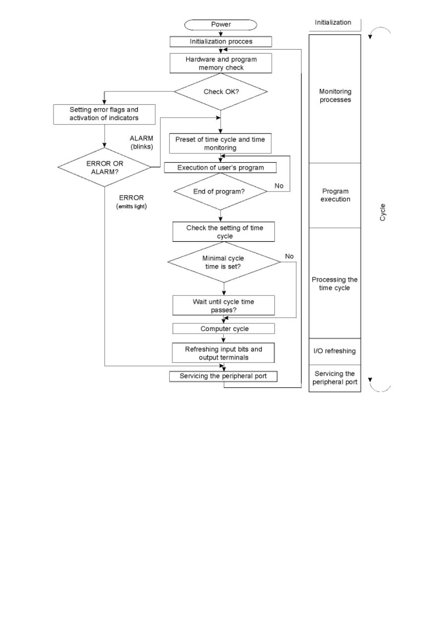
APPENDIX C - PLC diagnostics
C.1 Diagnostic functions of PLC
PLC controller features additional functions that make locating errors easier. Errors can be divided into two
categories according to severity :
1. Fatal errors are severe and they prevent PLC controller from operating until their cause is located and solved.
2. Non-fatal errors are those that do not prevent PLC controller from operating. After detecting one or more non-
fatal errors, program execution will continue. Nevertheless, it is necessary to correct these errors as soon as
possible.
C.2 Non-fatal errors
When one of these errors takes place, indicators POWER and RUN will be on, and the indicator ERR/ALM will blink.
Upon locating non-fatal error, manual for the given PLC controller should be consulted and the flags checked in
order to understand the cause of a problem and correct the error.
C.3 Fatal erros
When any of the fatal errors take place, PLC controller stops operating and all outputs are shut down. PLC
controller cannot be put back to work until the controller is turned off and then turned back on, or until it is
http://www.mikroelektronika.co.yu/english/product/books/PLCbook/app_c/app_c.htm (2 sur 5)05/11/2004 02:43:28

APPENDIX C - PLC diagnostics
switched to PROGRAM mode via peripheral device and the fatal error corrected. With these errors, indicators ERR/
ALM are on, while the RUN indicator remains off. It is necessary to check the error flag in the manual of the given
PLC in order to locate the cause of the problem and to correct the error.
C.4 User defined errors
There are three instructions for user to define his own errors or messages. FAL(06) causes non-fatal error, FAL(07)
causes fatal error, while MSG(46) sends a message to program console or to the host computer connected to the
PLC controller.
C.5 Failure alarm - FAL(06)
Instruction FAL(06) generates the code of non-fatal error that took place to provide the information on the possible
cause of the problem for the programmer. Upon execution of the instruction FAL(06) following events take place:
1. Indicator ERR/ALM will blink, while PLC continues to work.
2. Two-digits BCD number of instruction FAL (01 do 99) is written from SR253000 to SR25307.
Same number must not be assigned to both FAL and FALS instructions. To delete the code of an error, error should
be corrected and FAL 00 instruction executed.
C.6 Severe failure alarm - FALS(07)
Instruction FALS(07) generates the code of fatal error that took place. In this case the following happens:
1. Program stops and all outputs are shut down.
2. Indicator ERR/ALM is turned on.
3. Two-digit BCD number (01 do 99) of instruction FALS is written from SR 253000 to SR25307.
4. If memory card with RTC is used, part of the memory where the presence of error is recorded will also contain
numbers of FALS instruction and exact time when error took place.
Numbers of FALS instruction can be assigned to certain states. Same number must not be assigned to both FAL
and FALS instructions. To delete FALS error, PLC controller must be in PROGRAM mode, cause of error solved and
then error code deleted.
C.7 Message - MSG (46)
MSG(46) is used for printing messages on program console display. Message cannot exceed 16 characters, and it
appears when specified condition is fulfilled.
C.8 Syntax errors
During the program check with operation Program Check, syntax errors are detected. There are three levels of
program check at user’s disposal. By selecting the level, types of errors to be checked for are selected. The
following table shows types of errors, corresponding messages that appear on display and explains all of syntax
errors. Zero level check searches for errors of A, B and C type. First level check searches for errors of A and B
type, while the second searches only for errors of type A.
Type
Message
Meaning and the appropriate action
A
?????
Program is damaged by creating non-existing function in the code. Re-
enter your program.
CIRCUIT ERR
Number of logical blocks doesn't match the instructions of logical blocks.
Check the program.
OPERAND ERR
Entered constant is not in allowed range. Change the constant so that it
fits in the proper range.
NO END INSTR
Program is missing the instruction END(01). Add END(01) to the last
address of the program.
LOCN ERR
Instruction is in the wrong place of the program. Check what the
instruction demands and correct the mistake.
http://www.mikroelektronika.co.yu/english/product/books/PLCbook/app_c/app_c.htm (3 sur 5)05/11/2004 02:43:28
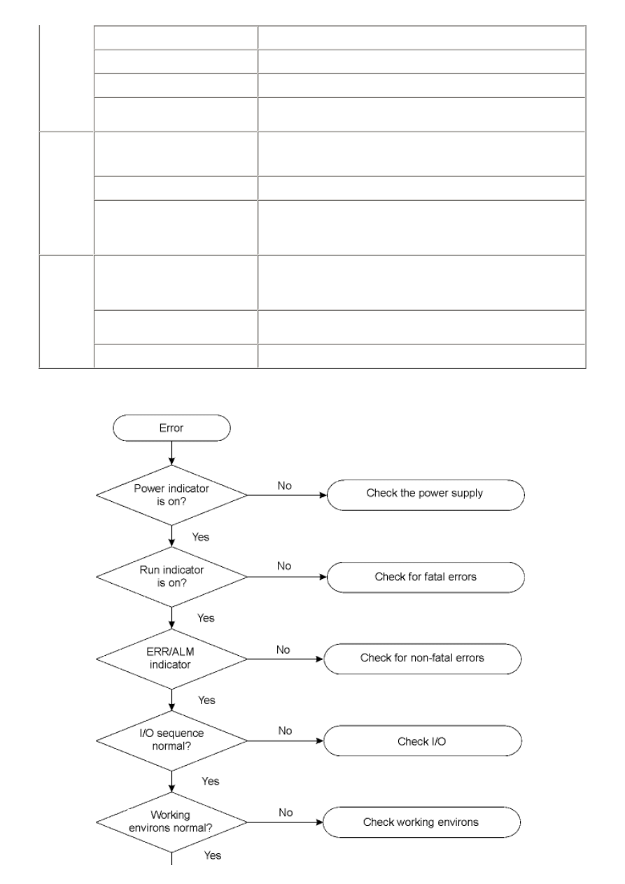
APPENDIX C - PLC diagnostics
JME UNDEFD
Instruction JME(04) is missing the instruction JMP(05). Correct the
number of jump and add the correct JME(04) instruction.
DUPL
Same number of jump or subroutine is used twice in the program.
Correct the program so that each number is used only once.
SBN UNDEFD
Instruction SBS(091) is programmed for non-existing subroutine. Correct
the number of subroutine or create the missing one.
STEP ERR
STEP(08) with the number of section and STEP(08) without the number
of section are used illegally. Check the demands of instruction STEP(08)
and correct the mistake.
B
IL-ILC-ERR
IL(02) and ILC(03) are not used in pair. Check if every instruction IL(02)
has its corresponding ILC(03). This message will also appear in case that
multiple IL(02) instructions were used with single ILC(03) instruction.
Check if that's exactly what you wanted...
JMP=JME ERR
JMP(04) and JME(05) are not used in pair. Before proceeding, check if
the program is written exactly the way you wanted.
SEN-RET ERR
If the address of instruction SBN(92) is displayed, there are two different
subroutines with the same number. Change one of the numbers or delete
one of the subroutines in question. If the address of instruction RET(93)
is displayed, RET(93) wasn't used appropriately. Check the demands of
this instruction and correct the mistake.
C
COIL DUPL
Same bit is controlled by more than one instruction (for example, OUT,
OUT NOT, DIFU(13), KEEP(11), SFT(10)...). Although certain instructions
allow this, you should check the demands of specific instructions, make
sure that the program is correct or rearrange the program so that each
bit is controlled by single instruction.
JMP UNDEFD
JME(05) is used without JMP(04) with the same number of jump. Add the
instruction JMP(04) with the same number or delete JME(05) that is not
used.
SBS UNDEFD
There is a subroutine that is not called by SBS(91). Add subroutine call
to an appropriate place in the program or delete the subroutine.
C.9 Algorithm for finding errors in the program
http://www.mikroelektronika.co.yu/english/product/books/PLCbook/app_c/app_c.htm (4 sur 5)05/11/2004 02:43:28

APPENDIX C - PLC diagnostics
© C o p y r i g h t 2 0 0 3. m i k r o E l e k t r o n i k a. All Rights Reserved. For any comments contact
.
http://www.mikroelektronika.co.yu/english/product/books/PLCbook/app_c/app_c.htm (5 sur 5)05/11/2004 02:43:28
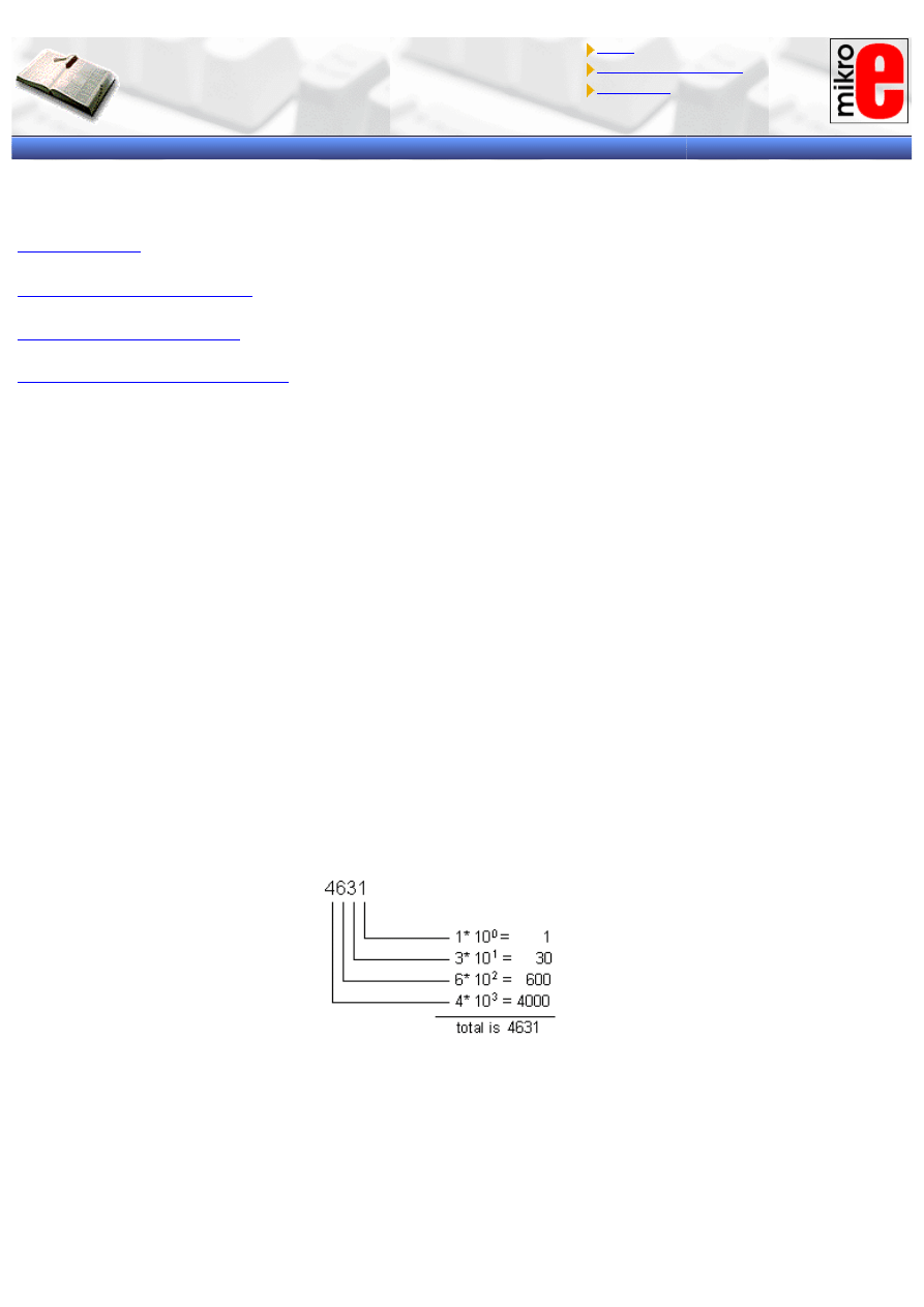
APPENDIX D - Numerical systems
Introduction to PLC controllers
on-line
FREE
!
Index
Development systems
Contact us
APPENDIX D
Numerical systems
D.3 Hexadecimal numerical system
Introduction
People were always difficult to except the fact that something is different from themselves or their way of thinking.
It is probably one of the reasons why numerical systems other than decimal are hard to understand. Still, whether
we like it or not, reality is quite different. Decimal system used in everyday life is by far less used than binary
code, which is the working basis for millions of computers across the world.
Each numerical system rests upon its basis. With decimal numerical system, this basis is 10, with binary it is 2,
while with hexadecimal it equals 16. Value of each digit depends on it’s position in the number, represented in
certain numerical system. Sum of values of each digit is the value of the number. Binary and hexadecimal systems
are especially interesting for this course. Besides these two, decimal system will be detailed, too, for the sake of
comparison. Although there is nothing new to tell about decimal system, we will give it a look for its relations with
other numerical systems.
D.1 Decimal numerical system
Decimal numerical system is defined with its basis 10 and decimal positioning from right to left, and it consists of
digits 0,1,2,3,4,5,6,7,8,9. This means that the rightmost digit is multiplied by 1 in total sum, next digit to it is
multiplied by 10, next one by 100, etc.
Example:
Operations of addition, subtraction, division and multiplication in decimal numerical system are well known, so we
will not detail these.
D.2 Binary numerical system
Binary numerical system is quite different from the decimal that we got used to in common life. Its basis is 2 and
each digit can have one of two values, “1” or “0”. Binary numerical system is used for computers and
microcontrollers, because it is much easier for processing than decimal. Usually, binary number consists of 8, 16 or
32 binary digits. Origins of this division are irrelevant for this course, so we will just take it for granted.
http://www.mikroelektronika.co.yu/english/product/books/PLCbook/app_d/app_d.htm (1 sur 4)05/11/2004 02:43:51
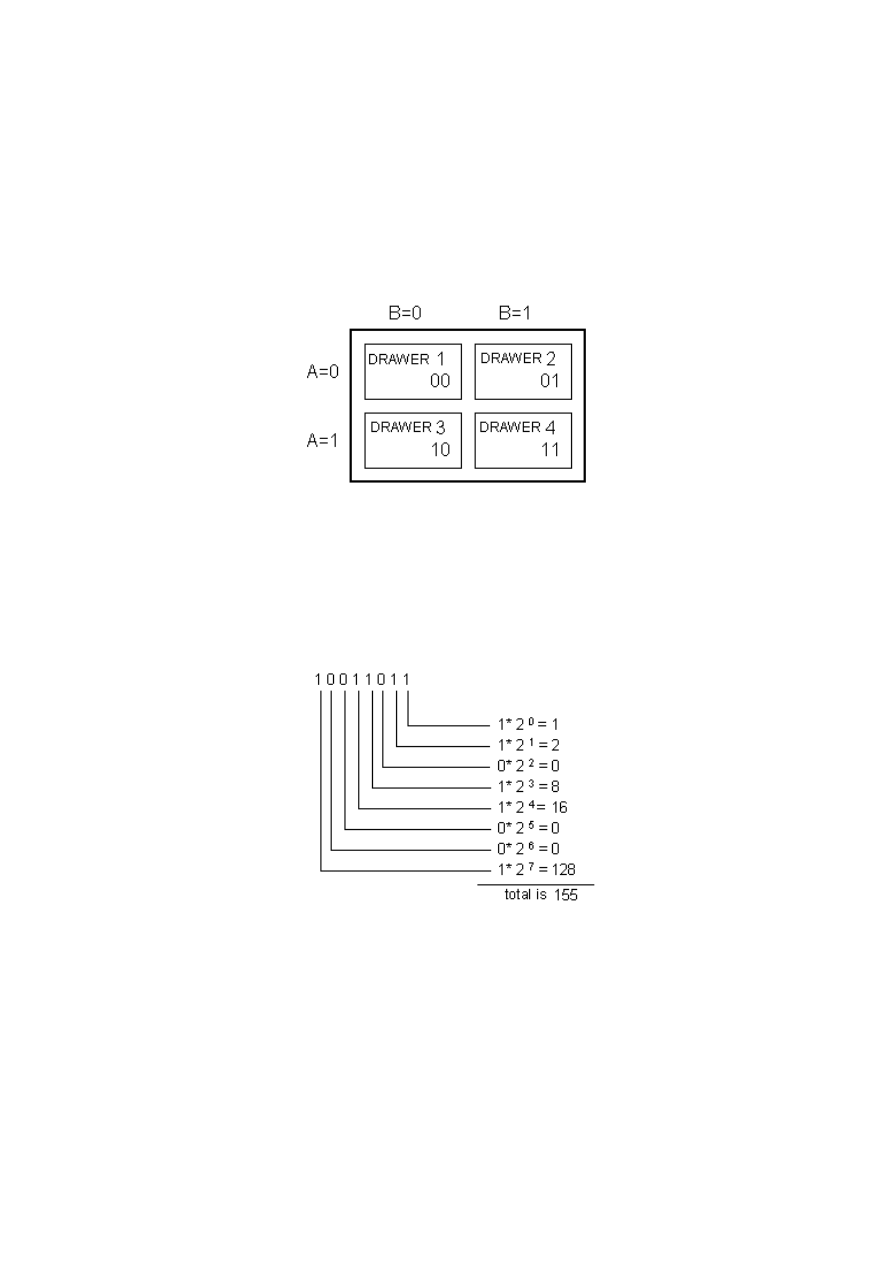
APPENDIX D - Numerical systems
Example:
10011011 - binary number with 8 digits
To understand the logic of binary numbers, let us have an example. Let’s assume that we have a cabinet with four
drawers and that we should tell someone to bring us something from one of these. Nothing simpler, we could say
“in the lower row on the left” and it would be quite sufficient. However, if it must be done without this kind of
orientation, left, right, up, down and the likes, then we have a problem. There is a plenty of solutions for the
situation, but we should look for the best and the most efficient! Let us mark the columns with A and rows with B.
If A=1, we assume the upper row of drawers, and if A=0 we assume the lower. Similar with columns, B=1 is the
left column and B=0 is the right column (following picture). Now, it is easier to explain which drawer we think of,
just use one of the four combinations 00, 01, 10 or 11. This “naming” of each drawer is nothing more than binary
nomenclature of numbers, that is, converting decimal numbers into binary system. In short, labels “first, second,
third and fourth” are substituted with “00, 01, 10 and 11”.
We still need to understand the logic of binary numerical system, i.e. how to get the decimal value of a number out
of the sequence consisting of ones and zeros. This procedure is called conversion of binary number to decimal
value.
As it can be seen, conversion of binary number to decimal value is done by totaling the sum on the right.
Depending on the position in the binary number, digits carry different “weight” multiplied by themselves, and
totaling them all gives us an understandable decimal number.
Let’s further assume that there are marbles in each of the drawers, 2 in the first, 4 in the second, 7 in the third
and 3 in the fourth. Let the person opening the drawers also use the binary system. Under these conditions,
question would be “How many marbles are there in 01?”, and the answer would be “There are 100 marbles in 01!”
Notice that both question and answer are clear, although we did not use common terminology. Further, notice that
two digits are sufficient for decimal numbers from 0 to 3, and that all values greater than 3 require additional
binary digits. Thus, for 0 ~ 7 range, three digits are sufficient, four digits cover the range 0 ~ 15, etc. Simply put,
the greatest decimal number that can be represented with n binary digits is 2 raised to power n, decreased by one.
Example:
2
4
-1 = 16 - 1 = 15
So, 4 binary digits cover decimal values from 0 to 15, including the values “0” and “15”, which is 16 different
values.
Arithmetical operations that exist in decimal numerical system also apply in binary system. In this chapter, we will
http://www.mikroelektronika.co.yu/english/product/books/PLCbook/app_d/app_d.htm (2 sur 4)05/11/2004 02:43:51
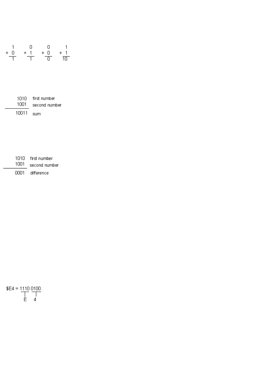
APPENDIX D - Numerical systems
cover only addition and subtraction, for simplicity sake.
Basic rules that apply to binary addition are:
Addition works similar to decimal numerical system - we add the digits of the same weight. If both digits added are
zero, the result remains zero, while “0” and “1” total “1”. Two ones give zero, but one is carried to the left position.
We can do the check by converting these numbers to decimal system and adding them. Value of the first number is
10, value of the second is 9 and 19 as result, which means that operation was done correctly. Problem occurs
when the result is greater than can be represented with given number of binary digits. There are various solutions,
one of them being expanding the number of binary digits like in the example below.
Subtraction works on the same principles as addition does. Two zeros give zero in result, as do two ones, while
subtraction of one from zero requires borrowing one from the higher position in binary number. Example:
Conversion of numbers to decimal system gives as values 10 and 9, with the result of subtraction of 1, which is
correct.
D.3 Hexadecimal numerical system
Hexadecimal numerical system has number 16 for basis. Therefore, there are 16 different digits used in this
system. These are “0, 1, 2, 3, 4, 5, 6, 7, 8, 9, A, B, C, D, E, F”. Letters A, B, C, D, E and F represent values 10, 11,
12, 13, 14, 15 and are used for the sake of easier notation. As with binary numerical system, we can apply the
same formula here for determining the greatest decimal number that can be represented with a given number of
hexadecimal digits.
Example:
16
2
- 1 = 256 - 1 = 255
Usually, hexadecimal numbers have prefix “$” or “0x” to emphasize the fact that hexadecimal system is used.
Thus, number A37E should be represented with $A37E or 0xA37E. No calculations are needed for converting the
hexadecimal number to binary system - it is simple substituting of hexadecimal digits with binary ones. Since
maximum value of hexadecimal digit is 15, 4 binary digits are required per one hexadecimal.
Example:
Check, i.e. converting both numbers to decimal system, gives us value 228 which is correct.
In order to calculate decimal equivalent of hexadecimal number, each digit of number should be multiplied by 16
raised to power equal to the position in the number and then added altogether.
http://www.mikroelektronika.co.yu/english/product/books/PLCbook/app_d/app_d.htm (3 sur 4)05/11/2004 02:43:51
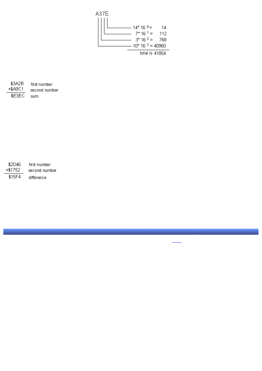
APPENDIX D - Numerical systems
Addition works similar to two previous numerical systems.
Example:
It is required to add the appropriate digits of a number, and if their sum equals 16, that position takes value “0”.
Values exceeding 16 should be added to the sum of digits on higher position. First number converted equals
14891, while other is 43457. Their sum is 58348, that is $E3EC converted to decimal numerical system.
Subtraction works identically to previously mentioned systems.
Example:
Conversion gives us numbers 11590 and 5970, and the result of subtractions is 5620, that is $15F4 converted to
decimal numerical system.
Conclusion
Binary numerical system remains the most commonly used, decimal system the most intelligible, while
hexadecimal is somewhere in between. It’s simple conversion to binary system makes it, besides binary and
decimal, the most important numerical system to us.
© C o p y r i g h t 2 0 0 3. m i k r o E l e k t r o n i k a. All Rights Reserved. For any comments contact
.
http://www.mikroelektronika.co.yu/english/product/books/PLCbook/app_d/app_d.htm (4 sur 4)05/11/2004 02:43:51
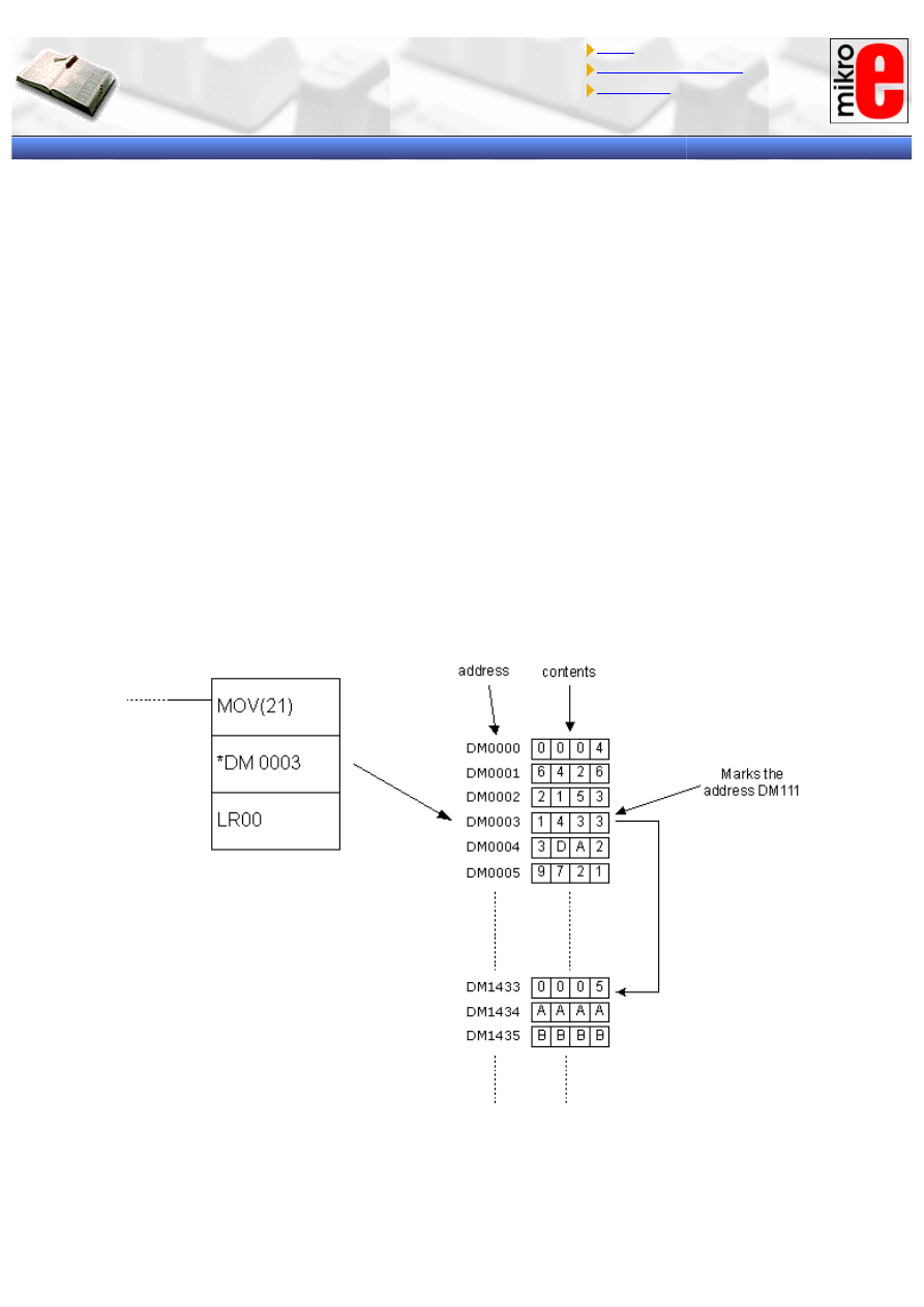
APPENDIX E - Ladder diagram instructions
Introduction to PLC controllers
on-line
FREE
!
Index
Development systems
Contact us
APPENDIX E
Ladder diagram instructions (1/3)
Introduction
"Ladder" is the most frequent method of programming PLC controllers at present. We could divide instructions on
the input ones for stating the conditions and the output ones that are executed when the conditions are fulfilled. By
combining the two, logical blocks are created according to the logic of the system being automated. The purpose of
this appendix is to introduce these instructions and to give details on flags and limitations of each of these.
INDIRECT ADDRESSING
Placing the character “*” ahead of operand from DM memory area allows us to use the indirect addressing. Simply
put, value in the word *DM will be the address of the word that is the true operand. The picture below shows the
MOV instruction with one operand given indirectly. The contents of location DM0003 equal “1433” which is actually
a pointer marking the address DM1433 with contents “0005”. The result of this instruction will be moving the value
“0005” from word DM1433 to word LR00.
In order to use the indirect addressing, contents of the word that is the indirect operand have to be in BCD format.
Besides that, value of the contents of indirect operand must not be greater than the number of addresses in DM
area.
INSTRUCTION FORMAT
Operand is the address of a word or a bit in PLC controller memory (most of the instructions has one or more
operands). The common term for a word is just “operand” and in the case of bit we call it “operand bit”. Also,
operand can be a direct numerical value marked by character “#” placed ahead of the value (i.e.. #12, #345 etc).
http://www.mikroelektronika.co.yu/english/product/books/PLCbook/app_e/app_e.htm (1 sur 19)05/11/2004 02:45:03
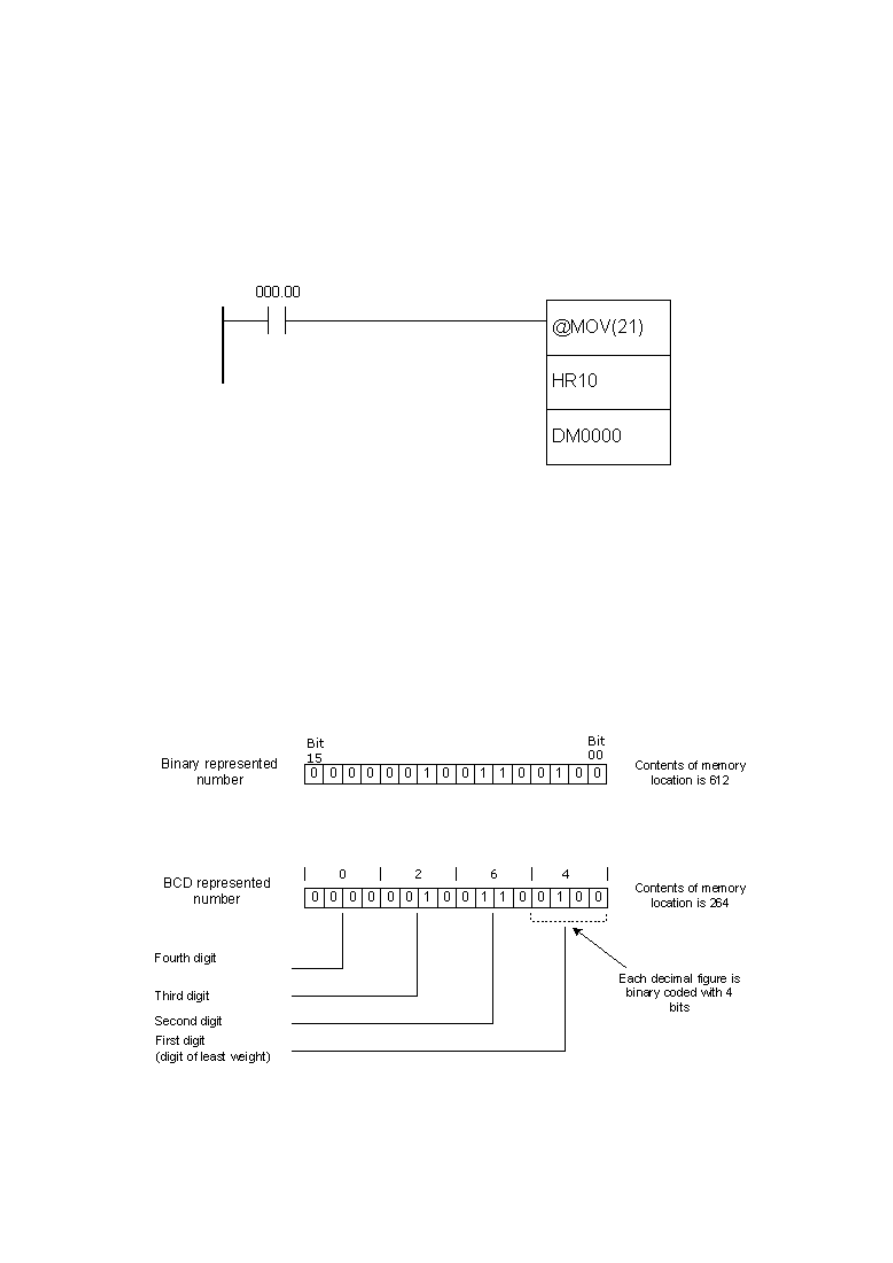
APPENDIX E - Ladder diagram instructions
The state of operand bit can be ON or OFF. ON means that its logic state equals “1”, while OFF stands for “0”.
Besides these, terms “set” and “reset” are also used.
Symbols SV and PV commonly appear in instruction syntax. These abbreviations stand for “Set Value” and
“Present Value” and are most frequently encountered with instructions concerning counters and timers.
DIFFERENTIAL INSTRUCTION FORM
Differential form is supported by almost all of the instructions. What differs this form from the classical one is the
character “@” placed ahead of the name of the instruction. This form ensures that the instruction with condition
fulfilled will not be executed in every cycle, but only when its condition changes state from OFF to ON. Differential
from is commonly used because it has a lot of applications in real-life problems.
DIFFERENCE BETWEEN BINARY AND BCD REPRESENTATIONS OF WORD CONTENTS
Generally, there are two dominant ways for comprehending values of memory locations. The first is binary and is
related to the contents of the word which is treated as a union of 16 bits. Value is calculated as a sum of each bit
(0 or 1) multiplied by 2 on power n, where n represents the position of bit in the word. Bit of the least value has
position zero, while bit of greatest value has position 15.
BCD is an abbreviation for “Binary Coded Decimal number”. It is nothing more than representing each decimal
figure with 4 bits, similar to binary coding hence the name comes from. The picture below shows the difference
between binary and BCD representations of the number. Same contents can be interpreted as either 612 or 264.
For that reason, proper attention should be given to the format of the value within the word that will be sent to the
instruction as an operand.
LADDER DIAGRAM INSTRUCTIONS
Instructions may be divided into several basic groups according to their purpose :
http://www.mikroelektronika.co.yu/english/product/books/PLCbook/app_e/app_e.htm (2 sur 19)05/11/2004 02:45:03
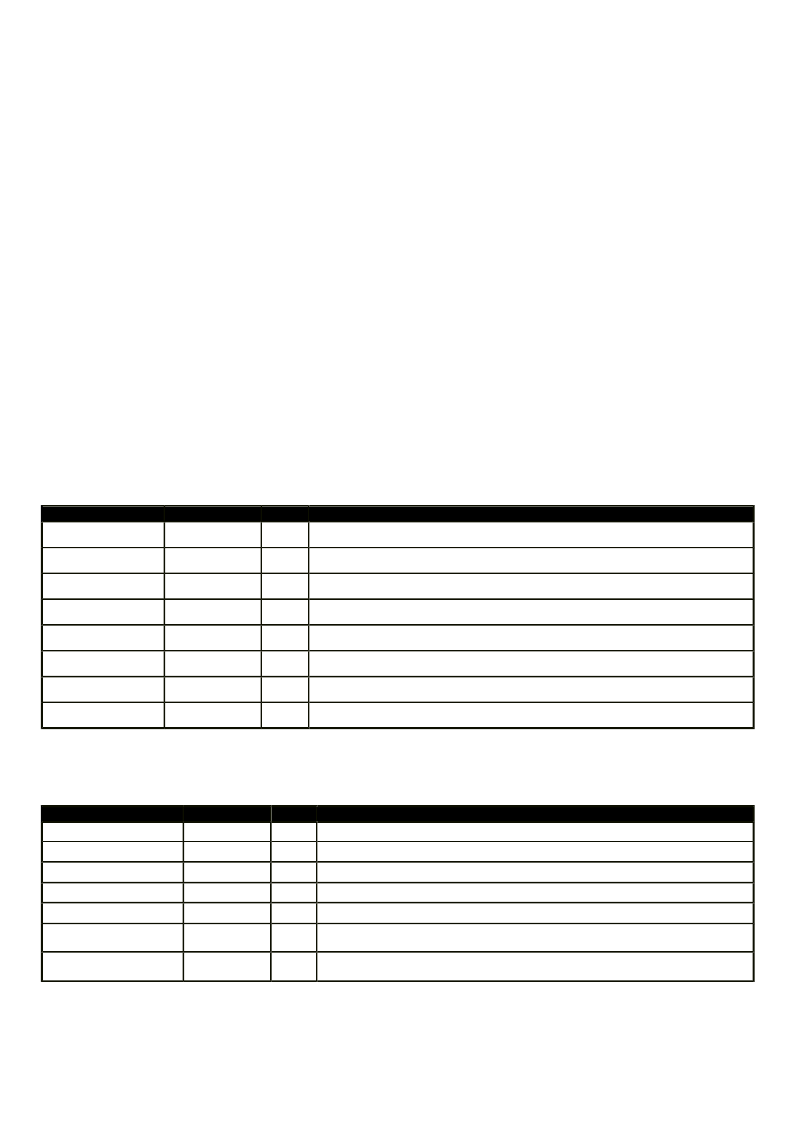
APPENDIX E - Ladder diagram instructions
- Input instructions
- Output instructions
- Control instructions
- Timer/counter instructions
- Data comparison instructions
- Data movement instructions
- Increment/decrement instructions
- BCD/binary calculation instructions
- Data conversion instructions
- Logic instructions
- Special calculation instructions
- Subroutine instructions
- Interrupt control instructions
- I/O units instructions
- Display instructions
- High-speed counter control instructions
- Damage diagnosis instructions
- Special system instructions
Each of these instruction groups is introduced with a brief description in the following tables and with more detailed
examples and descriptions afterwards.
Sequence Input Instructions
Instruction
Mnemonic
Code
Function
LOAD
LD
0
Connects an NO condition to the left bus bar.
LOAD NOT
LD NOT
0
Connects an NC condition to the left bus bar.
AND
AND
0
Connects an NO condition in series with the previous condition
AND NOT
AND NOT
0
Connects an NC condition in series with the previous condition
OR
OR
0
Connects an NO condition in parallel with the previous condition.
OR NOT
OR NOT
0
Connects an NC condition in parallel with the previous condition.
AND LOAD
AND LD
0
Connects two instruction blocks in series.
OR LOAD
OR LD
0
Connects two instruction blocks in parallel.
Sequence Output Instructions
Instruction
Mnemonic
Code
Function
OUTPUT
OUT
0
Outputs the result of logic to a bit.
OUT NOT
OUT NOT
0
Reverses and outputs the result of logic to a bit.
SET
SET
0
Force sets (ON) a bit.
RESET
RESET
0
Force resets (OFF) a bit.
KEEP
KEEP
11
Maintains the status of the designated bit.
DIFFERENTIATE UP
DIFU
13
Turns ON a bit for one cycle when the execution condition goes
from OFF to ON.
DIFFERENTIATE
DOWN
DIFD
14
Turns ON a bit for one cycle when the execution condition goes
from ON to OFF.
Sequence Control Instructions
http://www.mikroelektronika.co.yu/english/product/books/PLCbook/app_e/app_e.htm (3 sur 19)05/11/2004 02:45:03
APPENDIX E - Ladder diagram instructions
Instruction
Mnemonic Code
Function
NO OPERATION
NOP
00
---
END
END
01
Required at the end of the program.
INTERLOCK
IL
02
It the execution condition for IL(02) is OFF, all outputs are turned
OFF and all timer PVs reset between IL(02) and the next ILC(03).
INTERLOCK CLEAR ILC
03
ILC(03) indicates the end of an interlock (beginning at IL(02)).
JUMP
JMP
04
If the execution condition for JMP(04) is ON, all instructions
between JMP(04) and JME(05) are treated as NOP(OO).
JUMP END
JME
05
JME(05) indicates the end of a jump (beginning at JMP(04)).
Timer/Counter Instructions
Instruction
Mnemonic
Code
Function
TIMER
TIM
0
An ON-delay (decrementing) timer.
COUNTER
CNT
0
A decrementing counter.
REVERSIBLE COUNTER
CNTR
12
Increases or decreases PV by one.
HIGH-SPEED TIMER
TIMH
15
A high-speed, ON-delay (decrementing) timer.
Data Comparison Instructions
Instruction
Mnemonic
Code
Function
COMPARE
CMP
20
Compares two four-digit hexadecimal values.
DOUBLE COMPARE
CMPL
60
Compares two eight-digit hexadecimal values.
BLOCK COMPARE
(@)BCMP
68
Judges whether the value of a word is within 16 ranges
(defined by lower and upper limits).
TABLE COMPARE
(@)TCMP
85
Compares the value of a word to 16 consecutive words.
Data Movement Instructions
Instruction
Mnemonic
Code
Function
MOVE
(@)MOV
21
Copies a constant or the content of a word to a word.
MOVE NOT
(@)MVN
22
Copies the complement of a constant or the content of a word to a
word.
BLOCK TRANSFER (@)XFER
70
Copies the content of a block of up to 1,000 consecutive words to
a block of consecutive words.
BLOCK SET
(@)BSET
71
Copies the content of a word to a block of consecutive words.
DATA EXCHAGE
(@)XCHG
73
Exchanges the content of two words.
SINGLE WORD
DISTRIBUTE
(@)DIST
80
Copies the content of a word to a word (whose address is
determined by adding an offset to a word address).
DATA COLLECT
(@)COLL
81
Copies the content of a word (whose address is determined by
adding an offset to a word address) to a word.
http://www.mikroelektronika.co.yu/english/product/books/PLCbook/app_e/app_e.htm (4 sur 19)05/11/2004 02:45:03
APPENDIX E - Ladder diagram instructions
MOVE BIT
(@)MOVB
82
Copies the specified bit from one word to the specified bit of a
word.
MOVE DIGIT
(@)MOVD
83
Copies the specified digits (4-bit units) from a word to the
specified digits of a word.
Shift Instructions
Instruction
Mnemonic
Code
Function
SHIFT REGISTER
SFT
0/10 Copies the specified bit (0 or 1) into the rightmost bit of a shift
register and shifts the other bits one bit to the left.
WORD SHIFT
(@)WSFT
16
Creates a multiple-word shift register that shifts data to the left
in one-word units.
ASYNCHRONOUS
SHIFT REGISTER
(@)ASFT
17
Creates a shift register that exchanges the contents of adjacent
words when one is zero and the other is not.
ARITHMETIC SHIFT
LEFT
(@)ASL
25
Shifts a 0 into bit 00 of the specified word and shifts the other
bits one bit to the left.
ARITHMETIC SHIFT
RIGHT
(@)ASR
26
Shifts a 0 into bit 15 of the specified word and shifts the other
bits one bit to the right.
ROTATE LEFT
(@)ROL
27
Moves the content of CY into bit 00 of the specified word, shifts
the other bits one bit to the left, and moves bit 15 to CY.
ROTATE RIGHT
(@)ROR
28
Moves the content of CY into bit 15 of the specified word, shifts
the other bits one bit to the left, and moves bit 00 to CY.
ONE DIGIT SHIFT
LEFT
(@)SLD
74
Shifts a 0 into the rightmost digit (4-bit unit) of the shift register
and shifts the other digits one digit to the left.
ONE DIGIT SHIFT
RIGHT
(@)SRD
75
Shifts a 0 into the rightmost digit (4-bit unit) of the shift register
and shifts the other digits one digit to the right.
REVERSIBLE SHIFT
REGISTER
(@)SFTR
84
Creates a single or multiple-word shift register that can shift
data to the left or right.
Increment/Decrement Instructions
Instruction
Mnemonic
Code
Function
INCREMENT
(@)INC
38
Increments the BCD content of the specified word by 1.
DECREMENT
(@)DEC
39
Decrements the BCD content of the specified word by 1.
BCD/Binary Calculation Instructions
http://www.mikroelektronika.co.yu/english/product/books/PLCbook/app_e/app_e.htm (5 sur 19)05/11/2004 02:45:03
APPENDIX E - Ladder diagram instructions
Instruction
Mnemonic
Code
Function
BCD ADD
(@)ADD
30
Adds the content of a word (or a constant).
BCD SUBTRACT
(@)SUB
31
Subtracts the contents of a word (or constant) and CY from the
content of a word (or constant).
BDC MULTIPLY
(@)MUL
32
Multiplies the content of two words (or contents).
BCD DIVIDE
(@)DIV
33
Divides the contents of a word (or constant) by the content of a
word (or constant).
BINARY ADD
(@)ADB
50
Adds the contents of two words (or constants) and CY.
BINARY SUBTRACT (@)SBB
51
Subtracts the content of a word (or constant) an CY from the
content of the word (or constant).
BINARY MULTIPLY (©)MLB
52
Multiplies the contents of two words (or constants).
BINARY DIVIDE
(@)DVB
53
Divides the content of a word (or constant) by the content of a
word and obtains the result and remainder.
DOUBLE BCD ADD (@)ADDL
54
Add the 8-digit BCD contents of two pairs of words (or constants)
and CY.
DOUBLE BCD
SUBTRACT
(@)SUBL
55
Subtracts the 8-digit BCD contents of a pair of words (or
constants) and CY from the 80digit BCD contents of a pair
of words (or constants)
DOUBLE BCD
MULITPLY
(@)MULL
56
Multiplies the 8-digit BCD contents of two pairs of words (or
constants).
DOUBLE BCD
DIVIDE
(@)DIVL
57
Divides the 8-digit BCD contents of a pair of words (or
constants) by the 8–digits BCD contents of a pair of words
(or constants)
Data Conversion Instructions
Instruction
Mnemonic
Code
Function
BCD TO BINARY
(@)BIN
23
Converts 4-digit BCD data to 4-digit binary data.
BINARY TO BCD
(@)BCD
24
Converts 4-digit binary data to 4 digit BCD data.
4 to 16 DECODER
(@)MLPX
76
Takes the hexadecimal value of the specified digit(s) in a word
and turn ON the corresponding bit in a word(s).
16 to 4 DECODER
(@)DPMX
77
Identifies the highest ON bit in the specified word(s) and moves
the hexadecimal value(s) corresponding to its location to the
specified digit(s) in a word.
ASCII CODE
CONVERT
(@)ASC
86
Converts the designated digit(s) of a word into the equivalent 8-
bit ASCII code.
Logic Instructions
Instruction
Mnemonic
Code
Function
COMPLEMENT
(@)COM
29
Turns OFF all ON bits and turns ON all OFF bits in the specified
word
LOGICAL AND
(@)ANDW
34
Logically ANDs the corresponding bits of two word (or constants)
LOGICAL OR
(@)ORW
35
Logically ORs the corresponding bits of two word (or constants)
EXCLUSIVE OR
(@)XORW
36
Exclusively ORs the corresponding bits of two words (or constants)
EXCLUSIVE NOR
(@)XNRW
37
Exclusively NORs the corresponding bits of two words (or
constants).
http://www.mikroelektronika.co.yu/english/product/books/PLCbook/app_e/app_e.htm (6 sur 19)05/11/2004 02:45:03
APPENDIX E - Ladder diagram instructions
Special Calculation Instructions
Instruction
Mnemonic
Code
Function
BIT COUNTER
(@)BCNT
67
Counts the total number of bits that are ON in the specified block
Subroutine Instructions
Instruction
Mnemonic
Code
Function
SUBROUTINE
ENTER
(@)SBS
91
Executes a subroutine in the main program.
SUBROUTINE
ENTRY
SBN
92
Marks the beginning of a subroutine program.
SUBROUTINE
RETURN
RET
93
Marks the end of a subroutine program.
MACRO
MACRO
99
Calls and executes the specified subroutine, substituting the
specified input and output words for the input and output words in
the subroutine.
Interrupt Control Instructions
Instruction
Mnemonic
Code
Function
INTERVAL TIMER
(@)STIM
69
Controls interval timers used to perform scheduled interrupts.
INTERRUPT
CONTROL
(@)INT
89
Performs interrupts control, such as masking and unmasking the
interrupt bits for I/O interrupts.
Step Instructions
Instruction
Mnemonic
Code
Function
STEP DEFINE
STEP
08
Defines the start of a new step and resets the previous step
when used with a control bit. Defines the end of step
execution when used without a control bit.
STEP START
SNXT
09
Starts the execution of the step when used with a control
bit.
Peripheral Device Control Instructions
Instruction
Mnemonic
Code
Function
BCD TO BINARY
(@)BIN
23
Converts 4-digit BCD data to 4-digit binary data.
BINARY TO BCD
(@)BCD
24
Converts 4-digit binary data to 4-digit BCD data.
4 to 16 DECODER
(@)MLPX
76
Takes the hexadecimal value of the specified digit(s) in a word
and turn ON the corresponding bit in a word(s).
16 to 4 DECODER
(@)DPMX
77
Identifies the highest ON bit in the specified word(s) and moves
the hexadecimal value(s) corresponding to its location to the
specified digit(s) in a word.
ASCII CODE
CONVERT
(@)ASC
86
Converts the designated digit(s) of a word into the equivalent 8-
bit ASCII code.
http://www.mikroelektronika.co.yu/english/product/books/PLCbook/app_e/app_e.htm (7 sur 19)05/11/2004 02:45:03
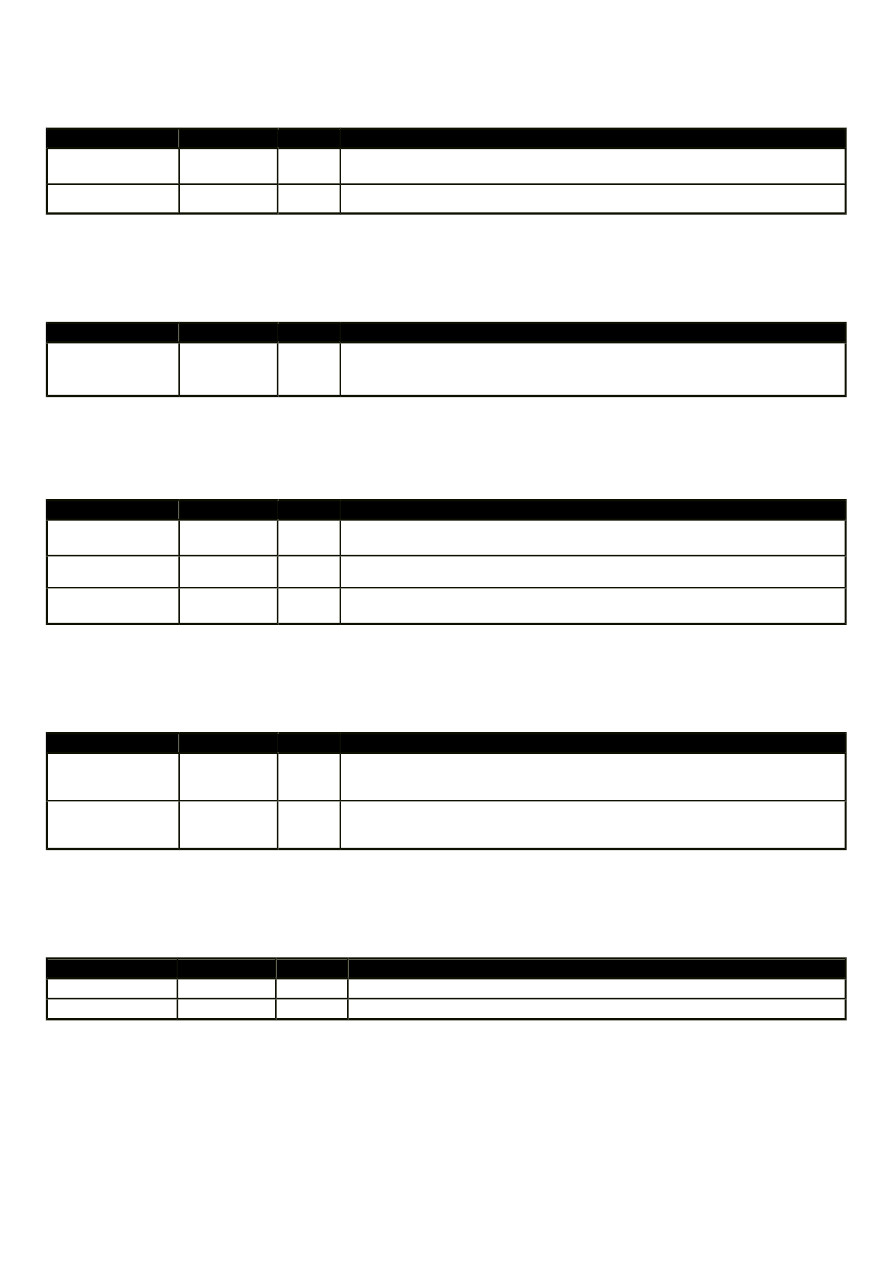
APPENDIX E - Ladder diagram instructions
I/O Units Instructions
Instruction
Mnemonic
Code
Function
7-SEGMENT
DECODER
(@)SDEC
78
Converts the designated digit(s)of a word into an 8-bit, 7-segment
display code.
I/O REFRESH
(@)IORF
97
Refreshes the specified I/O word.
Display Instructions
Instruction
Mnemonic
Code
Function
MEASSAGE
(@)MSG
46
Reads up to 8 words of ASCII code (16 characters) from memory and
displays the message on the Programming Console or other
Peripheral Device.
High Speed Counter Control Instructions
Instruction
Mnemonic
Code
Function
MODE CONTROL (@)INI
61
Starts and stops counter operation, compares and changes counter
PVs, and stops pulse output.
PV READ
(@)PRV
62
Reads counter PVs and status data.
COMPARE TABLE
LOAD
(@)CTBL
63
Compares counter PVs and generates a direct table or starts
operation.
Damage Diagnosis Instructions
Instruction
Mnemonic
Code
Function
FAILURE ALARM (@)FAL
06
Generates a non-fatal error when executed. The Error/Alarm indicator
flashes and the CPU continues operating.
SEVERE FAILURE
ALARM
FAL
07
Generates a fatal error when executed. The Error/Alarm indicator
lights and the CPU stops operating.
Special System Instructions
Instruction
Mnemonic
Code
Function
SET CARRY
(@)STC
40
Sets Carry Flag 25504 to 1.
CLEAR CARRY
(@)CLC
41
Sets Carry Flag 25504 to 0.
E.1 LOAD
- Normally open output
http://www.mikroelektronika.co.yu/english/product/books/PLCbook/app_e/app_e.htm (8 sur 19)05/11/2004 02:45:06
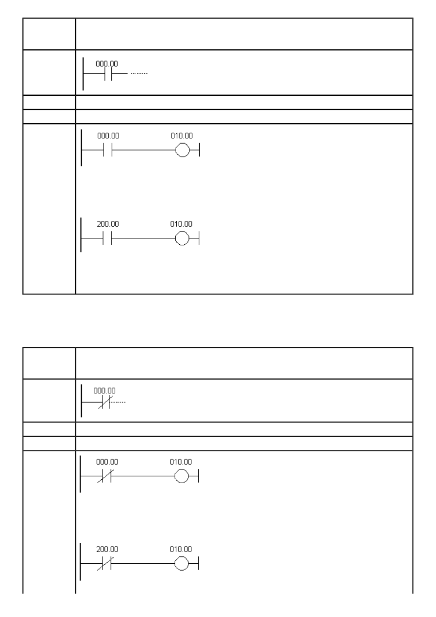
APPENDIX E - Ladder diagram instructions
Description
First condition, that any logical block in the ladder diagram starts with, corresponds to
LOAD or LOAD NOT instructions. Both of these instructions require one line in mnemonic
code. On the right of these instructions any executive instruction may be used.
Ladder
symbol
Limitations
There are no limitations, except that it is used as the first instruction from left to right.
Flag
It has no effect on any particular flag.
Example
Pressing the button on the input “00” in the word IR000 activates the relay “00” on the
output of PLC controller. Conditional instruction doesn’t have be from input memory area;
it can be any bit from other memory areas, i.e. SR area as in the following example.
When one of the instructions activates the bit “00” in the word SR200, bit “00” is
activated in the output word IR010. In a word, every ON state of the bit at input causes
the ON state at output.
E.2 LOAD NOT
- Normally closed input
Description
First condition, that any logical block in the ladder diagram starts with, corresponds to
LOAD or LOAD NOT instructions. Both of these instructions require one line in mnemonic
code. On the right of these instructions any executive instruction may be used.
Ladder
symbol
Limitations
There are no limitations, except that it is used as the first instruction from left to right.
Flag
It has no effect on any particular flag.
Example
Pressing the button on the input “00” in the word IR000 activates the relay “00” on the
output of PLC controller. Conditional instruction doesn’t have be from input memory area;
it can be any bit from other memory areas, i.e. SR area as in the following example.
http://www.mikroelektronika.co.yu/english/product/books/PLCbook/app_e/app_e.htm (9 sur 19)05/11/2004 02:45:06
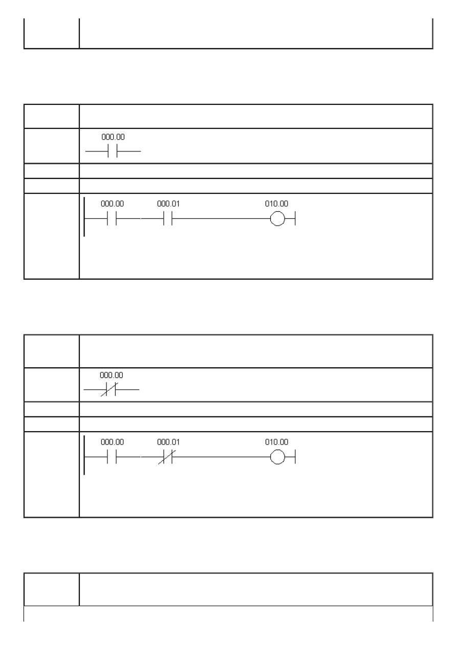
APPENDIX E - Ladder diagram instructions
When one of the instructions activates the bit “00” in the word SR200, bit “00” is
activated in the output word IR010. In a word, every ON state of the bit at input causes
the OFF state at output.
E.3 AND
- Logical "AND" with normally open contacts
Description
When two are linked serially in one instruction line, first of them corresponds to
instructions LOAD or LOAD NOT, while the other represents instructions AND or AND NOT.
Ladder
symbol
Limitations
There are no limitations.
Flag
It has no effect on any particular flag.
Example
After the LOAD instruction on ‘00’ input, AND instruction is linked to input ‘01’. Instruction
on the right will be executed only when both of the conditions from the line are fulfilled, i.
e. when both inputs ‘00’ and ‘01’ are in the ON state.
E.4 AND NOT
- Logical "AND" with normally closed contacts
Description
When two or more conditions are linked serially in one instruction line, first of them
corresponds to instruction LOAD or LOAD NOT, while the other represents instruction AND
or AND NOT.
Ladder
symbol
Limitations
There are no limitations.
Flag
It has no effect on any particular flag.
Example
After the LOAD instruction on ‘00’ input, AND NOT instruction is linked to input ‘01’.
Instruction on the right will be executed only when both of the conditions from the line
are fulfilled, i.e. when input ‘00’ is in ON state and input ‘01’ is in OFF state.
E.5 OR
- Logical "OR" with normally open contacts
Description
When two or more conditions coexist on separate, paralel lines that connect at a given
point, the first condition corresponds to LOAD or LOAD NOT instructions, while others
correspond to OR or OR NOT instructions.
http://www.mikroelektronika.co.yu/english/product/books/PLCbook/app_e/app_e.htm (10 sur 19)05/11/2004 02:45:06
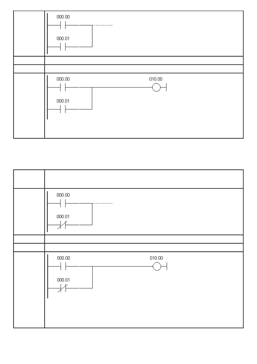
APPENDIX E - Ladder diagram instructions
Ladder
symbol
Limitations
There are no limitations.
Flag
It has no effect on any particular flag.
Example
Inputs ‘00’ and ‘01’ are in OR relation with the output ‘00’. One of the inputs with ON
state is sufficient to activate the output ‘00’.
E.6 OR NOT
- Logical "OR" with normally closed contacts
Description
When two or more conditions coexist on separate, paralel lines that connect at a given
point, the first condition corresponds to LOAD or LOAD NOT instructions, while others
correspond to OR or OR NOT instructions.
Ladder
symbol
Limitations
There are no limitations.
Flag
It has no effect on any particular flag.
Example
Inputs ‘000.00’ and ‘000.01’ are in OR NOT relation with the output ‘010.00’. Bit ‘010.00’
will retain ON state until bit “01” changes to ON state (thus breaking the connection,
because it is normally closed). One of the inputs with ON state is sufficient to activate the
output ‘00’.
http://www.mikroelektronika.co.yu/english/product/books/PLCbook/app_e/app_e.htm (11 sur 19)05/11/2004 02:45:06
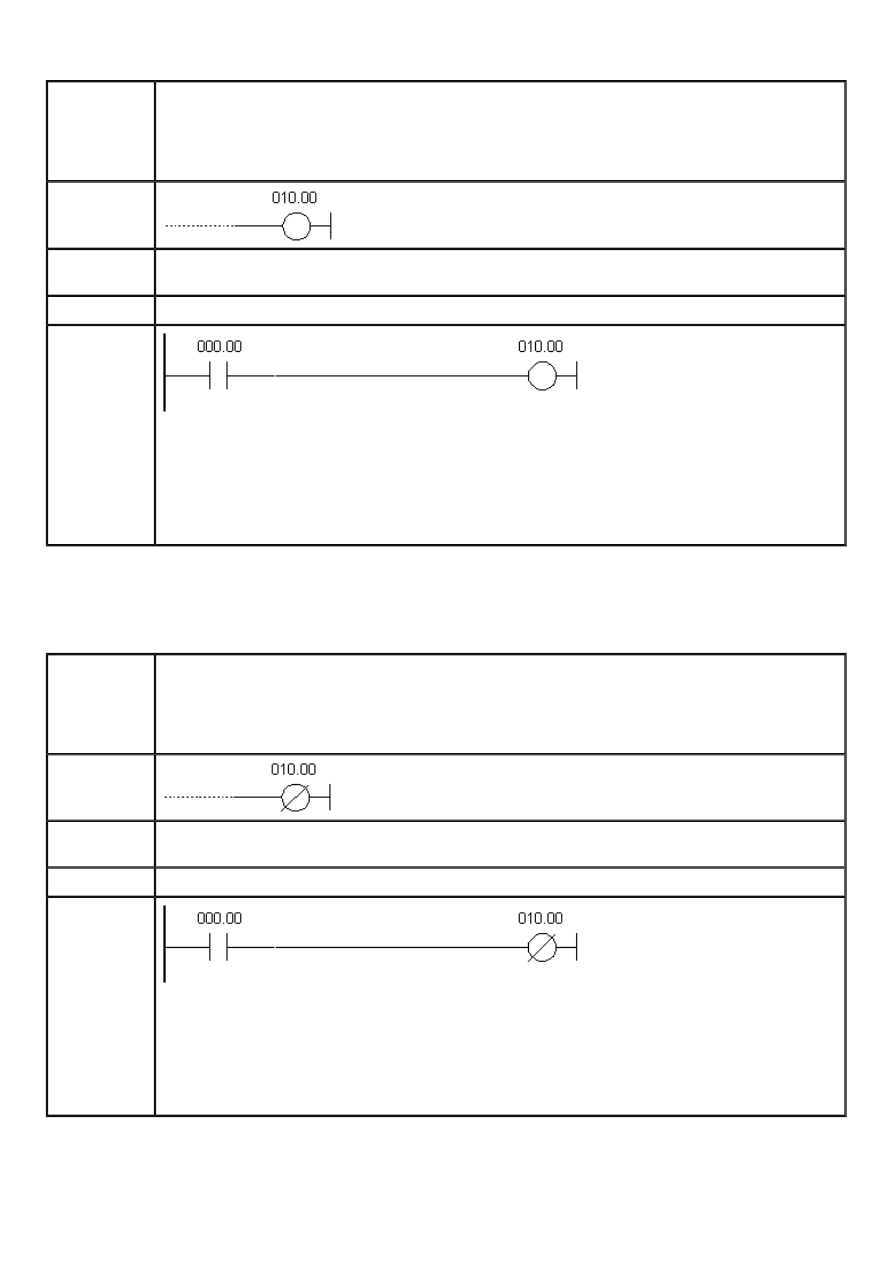
APPENDIX E - Ladder diagram instructions
E.7 OUTPUT
- Normally open output
Description
The easiest way for getting results that fulfill input conditions is their direct connection to
the instructions OUTPUT and OUTPUT NOT. These instructions are used for controlling the
status bit, which is defined as the instruction carrier. When OUTPUT instruction is used,
bit assigned to it will be ON if the execution condition is ON, and it will be OFF if the
execution condition is OFF.
Ladder
symbol
Limitations
Attention should be paid not to “overlap” the instructions concerning the bit being
controlled.
Flag
It has no effect on any particular flag.
Example
Bit IR010.00 will remain ON as long as bit IR000.00 is ON. When bit IR000.00 changes to
OFF, bit IR010.00 also changes to OFF.
This instruction cannot be used for assigning ON or OFF states to more than one bit. In
case that there is a need for assigning values to all of the bits in word, it can be done
only one bit at a time.
E.8 OUTPUT NOT
- Normally closed output
Description
The easiest way for getting results that fulfill input conditions is their direct connection to
the instructions OUTPUT and OUTPUT NOT. These instructions are used for controlling the
status bit, which is defined as the instruction carrier. When OUTPUT instruction is used,
bit assigned to it will be ON if the execution condition is OFF, and it will be OFF if the
execution condition is ON.
Ladder
symbol
Limitations
Attention should be paid not to “overlap” the instructions concerning the bit being
controlled.
Flag
It has no effect on any particular flag.
Example
Bit IR010.00 will remain ON as long as bit IR000.00 is OFF, while prelaskom changing bit
IR000.00 to ON changes bit IR010.00 to OFF.
This instruction cannot be used for assigning ON or OFF states to more than one bit. In
case that there is a need for assigning values to all of the bits in word, it can be done
only one bit at a time.
E.9 SET
- Changes bit state to
ON
http://www.mikroelektronika.co.yu/english/product/books/PLCbook/app_e/app_e.htm (12 sur 19)05/11/2004 02:45:06
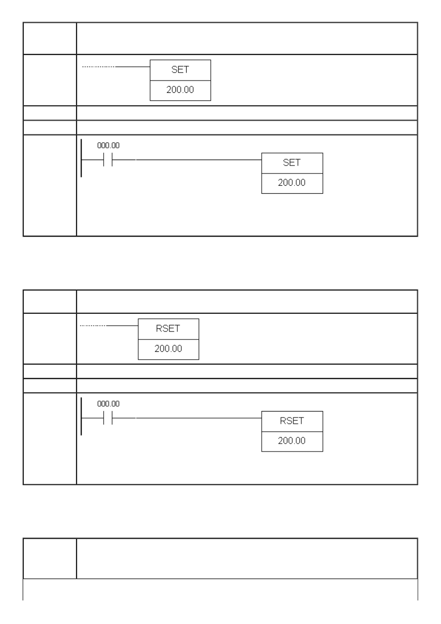
APPENDIX E - Ladder diagram instructions
Description
Instruction changes the state of the specified bit to ON when the execution condition is
ON. In case that the condition is OFF, bit state remains unchanged (unlike the instruction
OUT which changes bit state to OFF even when the condition is OFF).
Ladder
symbol
Limitations
There are no limitations.
Flag
It has no effect on any particular flag.
Example
If condition state on bit IR000.00 changes to ON, state of bit IR200.00 also changes to
ON. When condition state of bit IR000.00 changes from ON to OFF, bit IR200.00 remains
ON.
E.10 RESET
- Changes bit state to
OFF
Description
Instruction changes the state of the specified bit to OFF when the execution condition is
ON. In case that the condition is OFF, bit state remains unchanged.
Ladder
symbol
Limitations
There are no limitations.
Flag
It has no effect on any particular flag.
Example
If condition state on bit IR000.00 changes to ON, state of bit IR200.00 changes to OFF.
When condition state of bit IR000.00 changes from ON to OFF, bit IR200.00 remains OFF.
E.11 KEEP
- Changes bit state according to 2 inputs
Description
Instruction is used for maintaining the status of corresponding bit according to 2 inputs.
The first input changes bit state to ON whenever the condition of the first line is fulfilled,
while the second changes bit state to OFF whenever the condition of the second line is
fulfilled. Bit state remains unchanged as long as inputs remain unchanged.
http://www.mikroelektronika.co.yu/english/product/books/PLCbook/app_e/app_e.htm (13 sur 19)05/11/2004 02:45:06
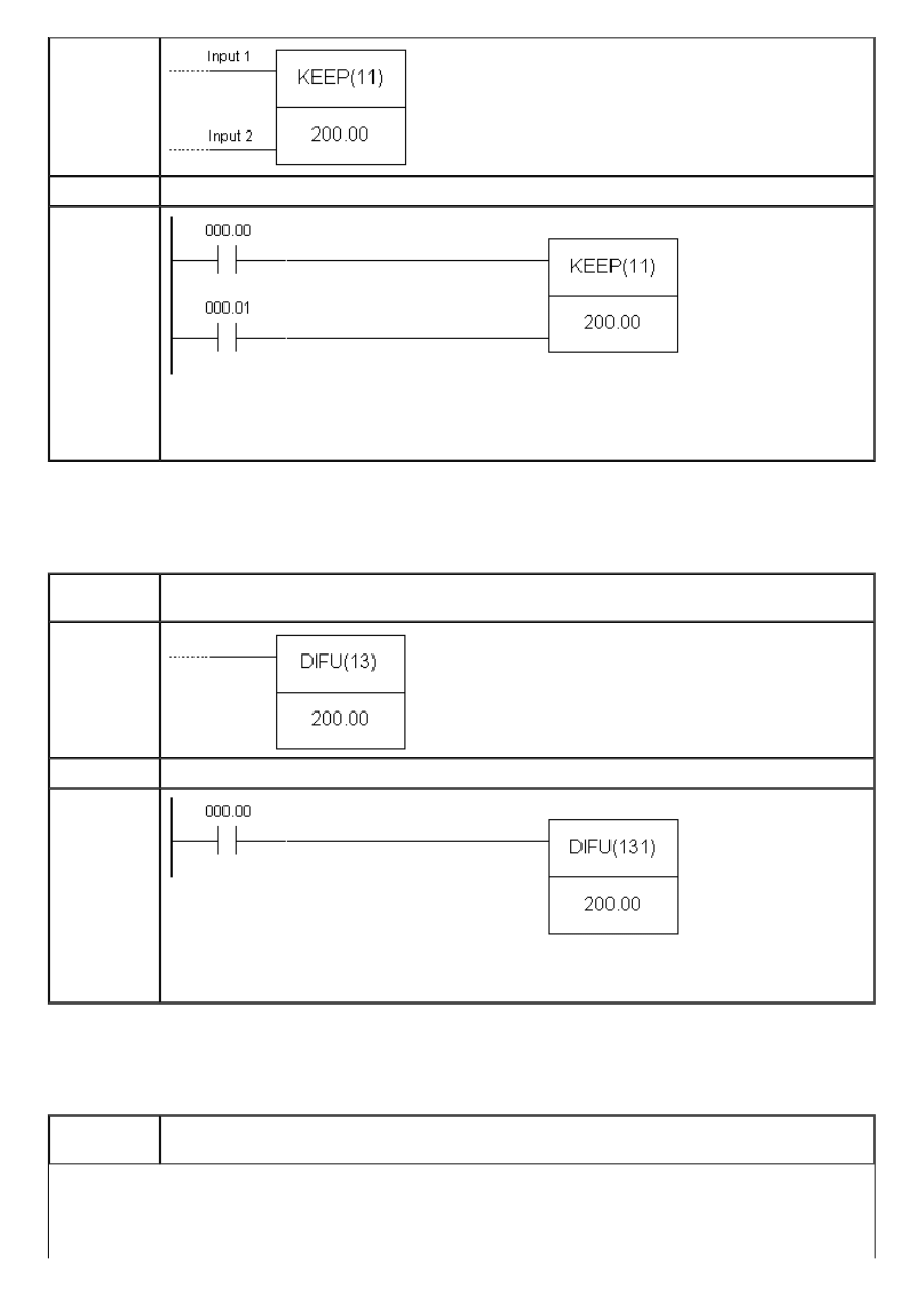
APPENDIX E - Ladder diagram instructions
Ladder
symbol
Flag
It has no effect on any particular flag.
Example
When the state of bit IR000.00 changes to ON bit IR200.00 also changes to ON. If bit
IR000.01 changes to ON, bit IR200.00 changes to OFF and remains OFF until state of bit
IR000.00 is ON again.
E.12 DIFFERENTIATE UP
- Changes bit state to
ON
for duration of one cycle
Description
Instruction changes bit state to ON during one cycle when the preceding condition is
fulfilled.
Ladder
symbol
Flag
It has no effect on any particular flag.
Example
Instruction changes state of bit IR200.00 to ON for duration of one cycle. If bit IR000.00
is ON, bit IR200.00 changes to ON for duration of one scan cycle.
E.13 DIFFERENTIATE DOWN
- Changes bit state to
OFF
for duration of one cycle
Description
Instruction changes bit state to OFF during one cycle when the preceding condition is
fulfilled.
http://www.mikroelektronika.co.yu/english/product/books/PLCbook/app_e/app_e.htm (14 sur 19)05/11/2004 02:45:06
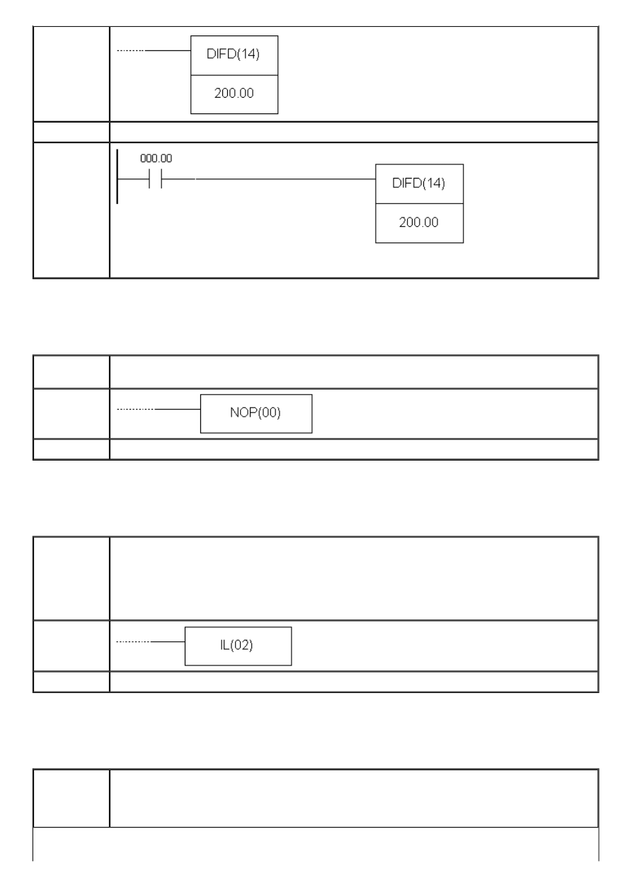
APPENDIX E - Ladder diagram instructions
Ladder
symbol
Flag
It has no effect on any particular flag.
Example
If bit IR000.00 is ON, state of bit IR200.00 changes to OFF for duration of one scan cycle.
E.14 NO OPERATION
- No operation
Description
Generally, usage of this instruction in programs is not recommended. When PLC gets to
this instruction nothing happens and the following instruction is executed.
Ladder
symbol
Flag
It has no effect on any particular flag.
E.15 INTERLOCK
- Interlock
Description
Instruction IL is always used in pair with the instruction ILC. Their purpose is to reset all
the outputs, flags, control bits, timers and counters that are within instructions between
IL and ILC. Timers and counters stop working and retain values they had at the moment
of executing IL instruction. It is possible to have multiple IL instructions and to reset one
or more parts of the program, accordingly. Instruction is executed when condition state
changes from ON to OFF!
Ladder
symbol
Flag
It has no effect on any particular flag.
E.16 INTERLOCK CLEAR
- End of the program part encompassed by interlock
Description
Instruction ILC is always used in pair with instruction IL. When the condition of instruction
IL is fulfilled all the outputs, flags, control bits, timers and counters that are within
instructions between IL and ILC are reset. Timers and counters stop working and retain
values they had at the moment of executing IL instruction.
http://www.mikroelektronika.co.yu/english/product/books/PLCbook/app_e/app_e.htm (15 sur 19)05/11/2004 02:45:06
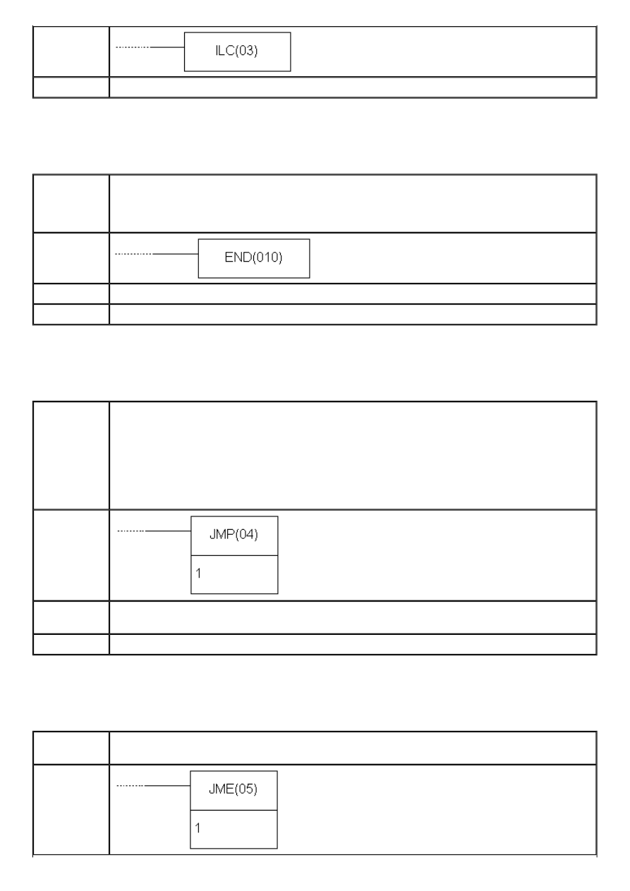
APPENDIX E - Ladder diagram instructions
Ladder
symbol
Flag
It has no effect on any particular flag.
E.17 END
- End of program
Description
This is mandatory instruction at the end of every program. Any instruction following this
one will not be executed. It can be used for debugging purposes in program, so as to
designate the point where the monitoring of program execution stops. If the program
uses subroutines, it is necesssary to have instruction END following the last subroutine.
Ladder
symbol
Limitations
There are no limitations.
Flag
Changes states of flags ER, CY, GR, EQ and LE to OFF.
E.18 JUMP
- Jump to another location in the program
Description
Certain part of the program may be skipped depending on the state of defined condition
for jump execution. Jumps can be created using JUMP (JMP(04)) or JUMP END (JME(05))
instructions. If condition state is ON, program executes normally, as if the instruction was
never used. If status of execution condition is OFF, program execution continues from the
JUMP END instruction corresponding to JUMP instruction. Which JUMP END corresponds to
which JUMP instruction is defined with a number that follows the instruction. Value 0 can
be used unlimited number of times in the course of program for this purpose, while each
of other 99 available numbers may be used only once.
Ladder
symbol
Limitations
Total number of JUMP and JUMP END pairs cannot exceed 99. Each value from 1-99 range
can be used only once.
Flag
It has no effect on any particular flag.
E.19 JUMP END
- Location where the program execution continues after
JUMP
Description
Instruction JME is used in pair with JMP instruction as integral part of it. If there is no JME
assigned to JMP instruction, program will report an error.
Ladder
symbol
http://www.mikroelektronika.co.yu/english/product/books/PLCbook/app_e/app_e.htm (16 sur 19)05/11/2004 02:45:06
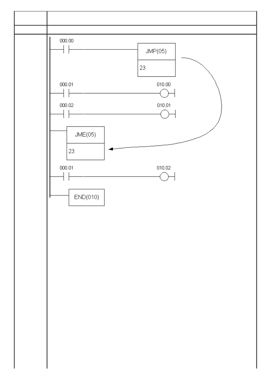
APPENDIX E - Ladder diagram instructions
Limitations
Total number of JUMP and JUMP END pairs cannot exceed 99. Each value from 1-99 range
can be used only once.
Flag
It has no effect on any particular flag.
Example
When the state of bit IR000.00 changes to OFF, jump instruction skips all the instruction
lines between itself and the corresponding JME instruction.
Another way for using jump instruction is assigning value “0” to JMP instruction.
Unlimited number of jumps can be programmed in this way and the destination for each
of these is a unique location defined with instruction JUMP END with index 0. Instruction
JUMP END with parameter 0 may be used multiple times in the program. In that case,
program execution after the jump defined with JUMP (index 0) continues from the first
following JUMP END instruction with this index. Time of execution with this form of jump
function is somewhat longer, as the program must first locate the closest appropriate
JUMP END instruction. The following example demonstrates programming greater number
of jump functions ending at the same destination:
Changing the state of bits IR000.00 or IR000.03 to OFF executes the jump to the line
containing instruction JME.
http://www.mikroelektronika.co.yu/english/product/books/PLCbook/app_e/app_e.htm (17 sur 19)05/11/2004 02:45:06
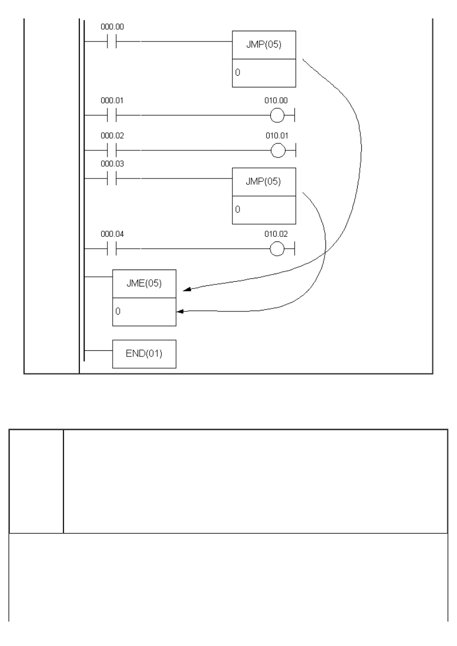
APPENDIX E - Ladder diagram instructions
E.20 TIMER
- Timer with 0.1s resolution
Description
Timers are complex instructions with the purpose of separating two programming actions.
Changing the state of condition to ON starts the timing with 0.1s increments starting from zero.
Value of parameter SV (abbreviation for Set Value) is multiplied by 0.1 s, the result being total
time in seconds. Value given in the middle part of the block is called TC number. Each TC number
can be used for defining one couner or timer. It can take values from 000 - 127 range. Lower
part of the block is reserved for displaying the starting value of timer. Word with this role can
belong to sectors IR, AR, DM, HR, LR or can be given as a constant, with values from 000.0 -
999.9 range. The most common and the simplest way to apply a timer is to have a constant here,
whether given directly or programmed on some memory location (if parameter SV is given as a
constant, it is necessary to put character “#” ahead of value).
http://www.mikroelektronika.co.yu/english/product/books/PLCbook/app_e/app_e.htm (18 sur 19)05/11/2004 02:45:06
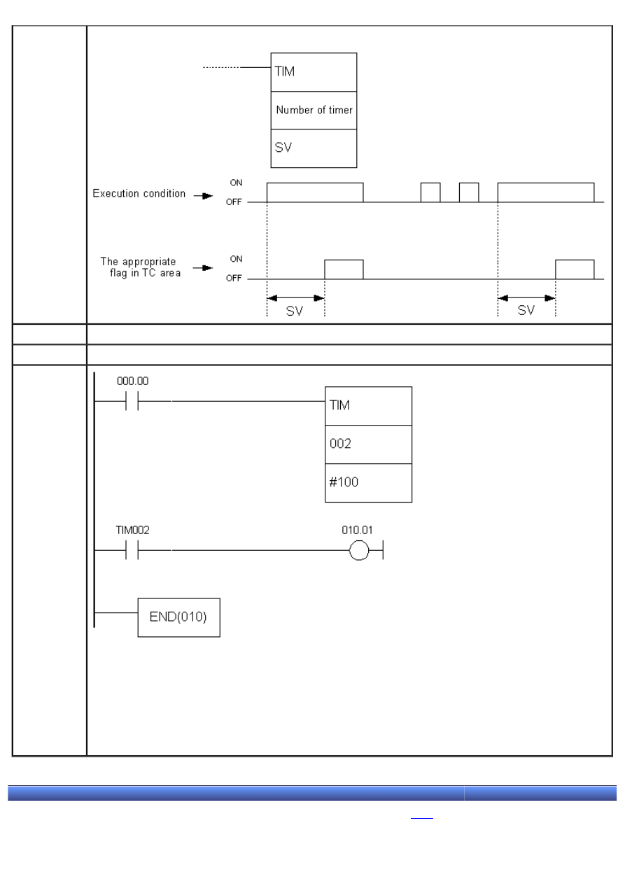
APPENDIX E - Ladder diagram instructions
Ladder
symbol
Limitations
The number of timer cannot be used for counter or another timer.
Flag
Affects the appropriate flag in TC area.
Example
Changing the state of bit IR000.00 to ON starts the timing (in this case, time is 100*0.1s=10
seconds). After the passing of given period of time, the appropriate bit IM002 changes state to
ON, thus fulfilling the condition for executing the instructions on the right (in this case bit
IR010.01 changes state to ON).
Condition bit must be constantly ON for a given time period for bit TIM002 to be set. If condition
state changes to OFF during the given time period, timer resets and goes back to the beginning of
period.
© C o p y r i g h t 2 0 0 3. m i k r o E l e k t r o n i k a. All Rights Reserved. For any comments contact
.
http://www.mikroelektronika.co.yu/english/product/books/PLCbook/app_e/app_e.htm (19 sur 19)05/11/2004 02:45:06
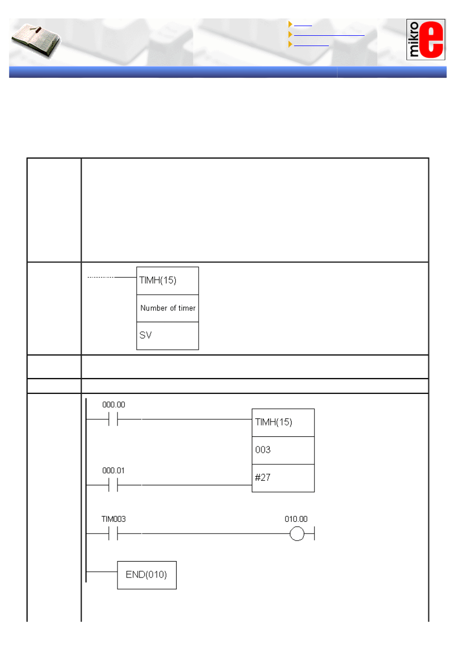
APPENDIX E - Ladder diagram instructions
Introduction to PLC controllers
on-line
FREE
!
Index
Development systems
Contact us
APPENDIX E
Ladder diagram instructions
(2/3)
E.21 HIGH-SPEED TIMER
- Timer with 0.01s resolution
Description
This instruction is identical to the previous TIM instruction, except for the resolution of
decrementing. In case of TIM instruction this interval equals 0.1s, while with TIMH
instruction it equals 0.01s. Changing the condition to ON starts the countdown with 0.01s
decrements from the predefined value down to zero. If the state of condition changes to
OFF timer will be reset. Value of parameter SV (abbreviation for Set Value) is multiplied
by 0.01 s resulting in total time in seconds. Value given in the middle part of the block is
called TC number. Each TC number can be used for defining one couner or timer. It can
take values from 000 - 127 range. Lower part of the block is reserved for displaying the
starting value of timer. Word with this role can belong to sectors IR, AR, DM, HR, LR or
can be given as a constant, with values from 00.00 - 99.9.9 range. If parameter SV is
given as a constant, it is necessary to put character “#” ahead of value.
Ladder
symbol
Limitations
The number of timer cannot be used for a counter or another timer. Value of SV must be
in 00.00 - 99.99 range. Recommended range for a number of timer is 000 - 003.
Flag
Affects the appropriate flag in TC area.
Example
Changing the state of condition bit IR000.00 to ON starts the countdown (in this case for
27*0.01s=0.27 seconds). After the passing of given period of time, the appropriate bit
http://www.mikroelektronika.co.yu/english/product/books/PLCbook/app_e/app_e1.htm (1 sur 32)05/11/2004 02:46:29
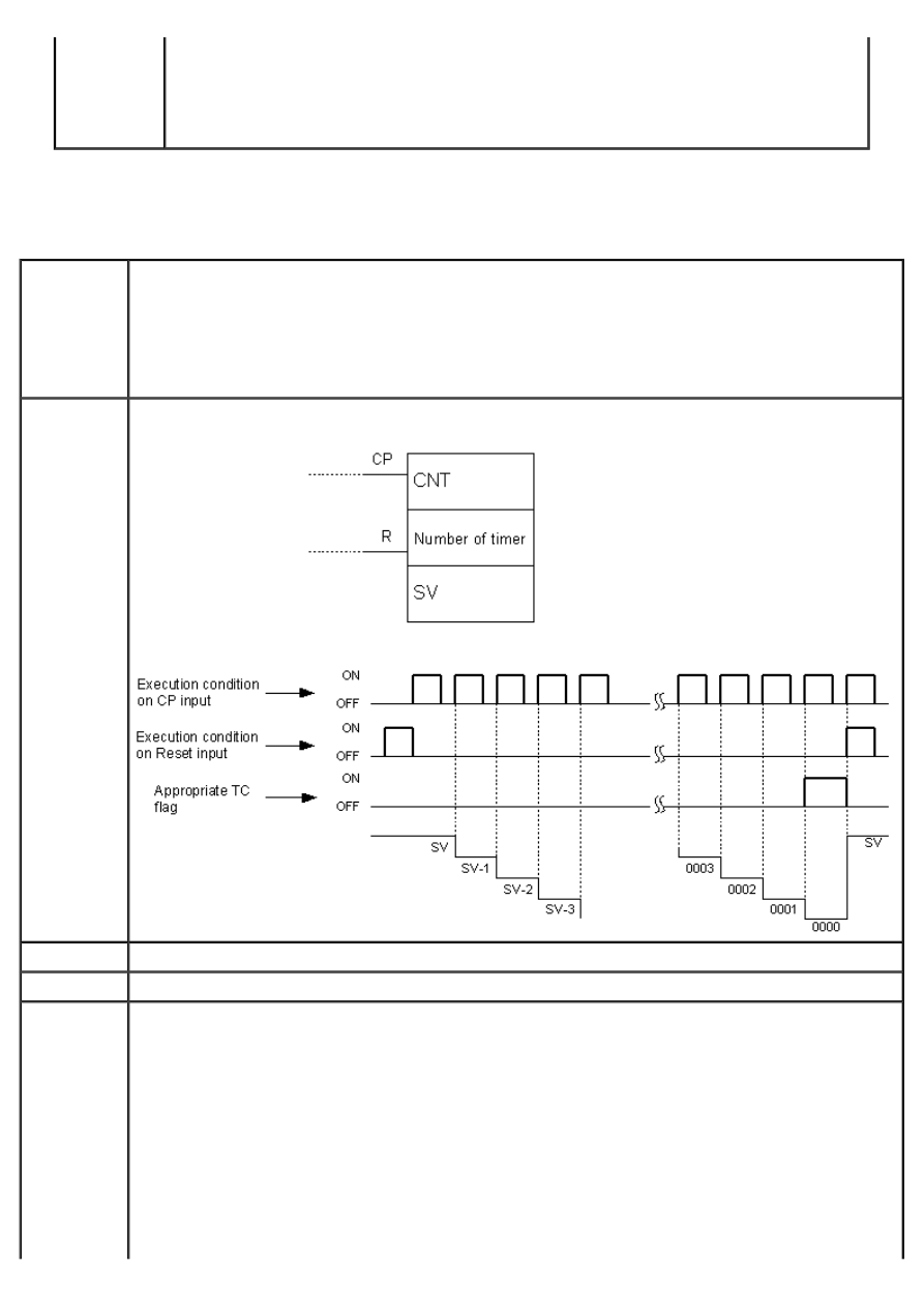
APPENDIX E - Ladder diagram instructions
IM003 changes state to ON, thus fulfilling the condition for executing the instructions on
the right (in this case bit IR010.01 changes state to ON).
Condition bit must be constantly ON for a given time period for bit TIM002 to be set. If
condition state changes to OFF during the given time period, timer resets and goes back
to the beginning.
E.22 COUNTER
- Counter
Description
Counter decrements the value given with SV for every ON state of the condition on CP line
(abbreviation for Count Pulse). Each time the state on CP line changes from OFF to ON value of SV
is decremented by one. Fulfilling the condition on R (reset) line sets the counter to a starting state
with a given SV value. When the zero is reached, instruction changes the state of appropriate bit
from TC area corresponding to the number of a counter (bit can be returned to OFF state by
fulfilling the condition on reset line). If parameter SV is given as a constant, it is necessary to place
a character “#” ahead of value.
Ladder
symbol
Limitations
The number of timer cannot be used for a counter or another timer.
Flag
Affects the appropriate flag in TC area.
Example
http://www.mikroelektronika.co.yu/english/product/books/PLCbook/app_e/app_e1.htm (2 sur 32)05/11/2004 02:46:29
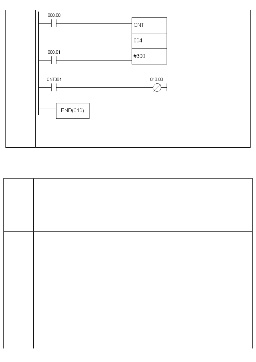
APPENDIX E - Ladder diagram instructions
When the state of bit IR000.00 changes from OFF to ON, counter value decreases to 299, next
change of bit IR000.00 lowers it to 298 and so on. When counter value reaches zero, state of bit
CNT004 changes to ON, fulfilling the condition for executing instructions on the right (in this case,
it is a normally closed contact that will open).
E.23 REVERSIBLE COUNTER
- Incrementing / decrementing counter
Description
This instruction is an extension of the previous one, having the added input for increasing counter
value by one. Counter CNTR has two counting inputs: incrementing and decrementing. Decrementing
input is identical to one from CNT instruction. For every ON state of condition on II line (Increment
Input) counter value increases by one. If this value reached SV, counter value remains unchanged.
Every time state on DI line (Decrement Input) changes from OFF to ON, value of SV decreases by
one. If counter value reached zero it remains unchanged. Fulfilling the condition on R (reset) line
sets the counter to a starting state given with value of SV. With reaching the zero, instruction
changes the state of bit in TC area appropriate to the number of the counter. This bit can be
returned to OFF state by fulfilling the condition on na reset line or increment II line. If the parameter
SV is given as a constant it is necessary to place the character “#” ahead of value.
Ladder
symbol
http://www.mikroelektronika.co.yu/english/product/books/PLCbook/app_e/app_e1.htm (3 sur 32)05/11/2004 02:46:29
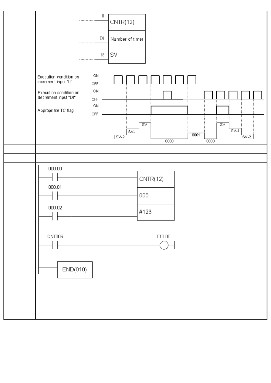
APPENDIX E - Ladder diagram instructions
Limitations
Number of a counter cannot be used for a timer or another counter.
Flag
Affects the appropriate bit in TC area.
Example
When the state of bit IR000.00 changes from OFF to ON, counter value decreases to 122, next
change of bit IR000.00 lowers it to 121 and so on. When the state of bit IR000.01 changes counter
value increases by one. When counter value reaches zero, state of bit CNT006 changes to ON
fulfilling the condition for executing instructions on the right (in this case, it is normally closed
contact that will open). ON state of bit IR00.02 will return the counter to a given value, while a bit
CNT006 returns it to OFF state.
E.24 COMPARE
- Compares two memory locations
http://www.mikroelektronika.co.yu/english/product/books/PLCbook/app_e/app_e1.htm (4 sur 32)05/11/2004 02:46:29
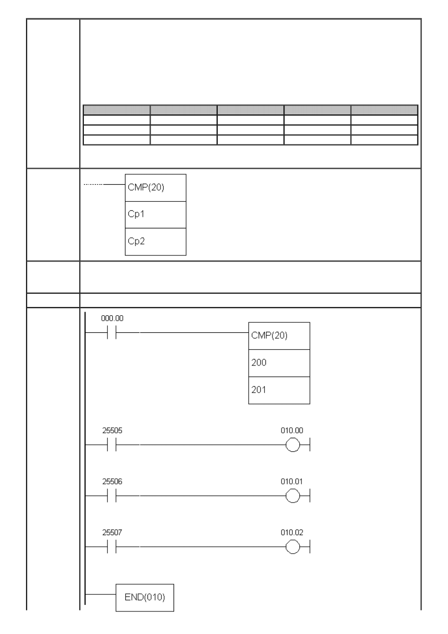
APPENDIX E - Ladder diagram instructions
Description
Instruction CMP(20) compares two words upon fulfilling the preceding condition.
Depending on the relation of the two words, output can be:
1. Equal - state of bit EQ in SR memory area changes to ON.
2. Cp1 is lower than Cp2 - state of bit LE in SR memory area changes to ON.
3. Cp1 is greater than Cp2 - state of bit GR in SR memory area changes to ON.
Flag
Address
Cp1<Cp2
Cp1=Cp2
Cp1>Cp2
GR
25505
OFF
OFF
ON
EQ
25506
OFF
ON
OFF
LE
25507
ON
OFF
OFF
Ladder
symbol
Limitations
Comparations that include the current values of timer or a counter require values in BCD
format. Checking the flags GR, LE and EQ should take place immediately after the CMP
(20) instruction, because another instruction may affect their states.
Flag
Affects the flags GR, LE and EQ in SR memory area.
Example
http://www.mikroelektronika.co.yu/english/product/books/PLCbook/app_e/app_e1.htm (5 sur 32)05/11/2004 02:46:29
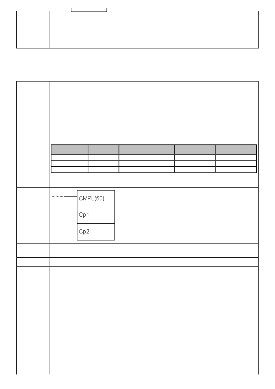
APPENDIX E - Ladder diagram instructions
When the state of bit IR000.00 changes to ON, condition for comparing the values of
memory locations IR200 and IR201 is fulfilled. If value of IR200 is greater than IR201,
state of bit IR010.00 changes to ON. If value of IR200 is lesser than IR201, state of bit
IR010.02 changes to ON. In case of equal values of locations IR200 and IR201, state of
bit IR010.01 changes to ON.
E.25 DOUBLE COMPARE
- Compares two consecutive words
Description
Instruction CMPL(60) compares the two consecutive words with other two consecutive
words. Depending on the relation, output can be:
1. Equal - state of bit EQ in SR memory area changes to ON.
2. Cp1+1, Cp1 is lower than Cp2+1, Cp2 - state of bit LE in SR memory area changes
to ON.
3. Cp1+1, Cp1 is greater than Cp2+1, Cp2 - state of bit GR in SR memory area changes
to ON.
Flag
Address
Cp1+1,Cp1 <Cp2+1,Cp2
Cp1+1,Cp1=Cp2
+1,Cp2
Cp1+1,Cp1>Cp2
+1,Cp2
GR
25505
OFF
OFF
ON
EQ
25506
OFF
ON
OFF
LE
25507
ON
OFF
OFF
Ladder
symbol
Limitations
Checking the flags GR, LE and EQ should take place immediately after the CMP(20)
instruction, because another instruction may affect their states.
Flag
Affects the flags GR, LE and EQ in SR memory area.
Example
http://www.mikroelektronika.co.yu/english/product/books/PLCbook/app_e/app_e1.htm (6 sur 32)05/11/2004 02:46:29
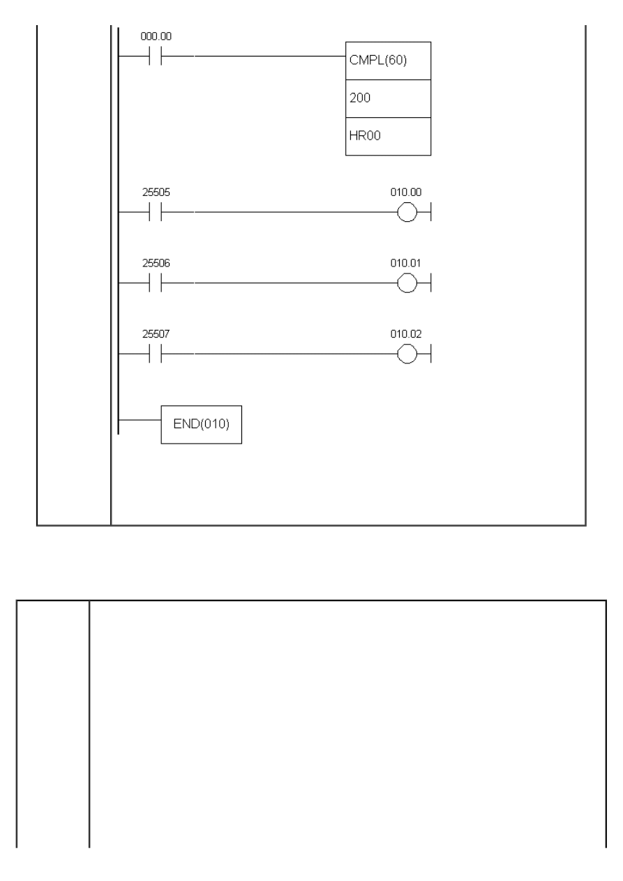
APPENDIX E - Ladder diagram instructions
When the state of bit IR000.00 changes to ON, condition for comparing the values of
memory locations IR200+IR2001 and HR00+HR01 is fulfilled. If value of the first operand
is greater, state of bit IR010.00 changes to ON. If value of the first operand is lesser,
state of bit IR010.02 changes to ON. In case of equal values, state of bit IR010.01
changes to ON.
E.26 BLOCK COMPARE
- Block compare
Description
Instruction BCMP compares the value of memory location CD with values of memory locations CB
- CB+31. The method consists of finding the pair of CB locations where the value of CD location
fits in between. Upon locating that area, the appropriate bit is set in the result word R. Based on
this information, the programmer knows the general area of value of location CD.
http://www.mikroelektronika.co.yu/english/product/books/PLCbook/app_e/app_e1.htm (7 sur 32)05/11/2004 02:46:29
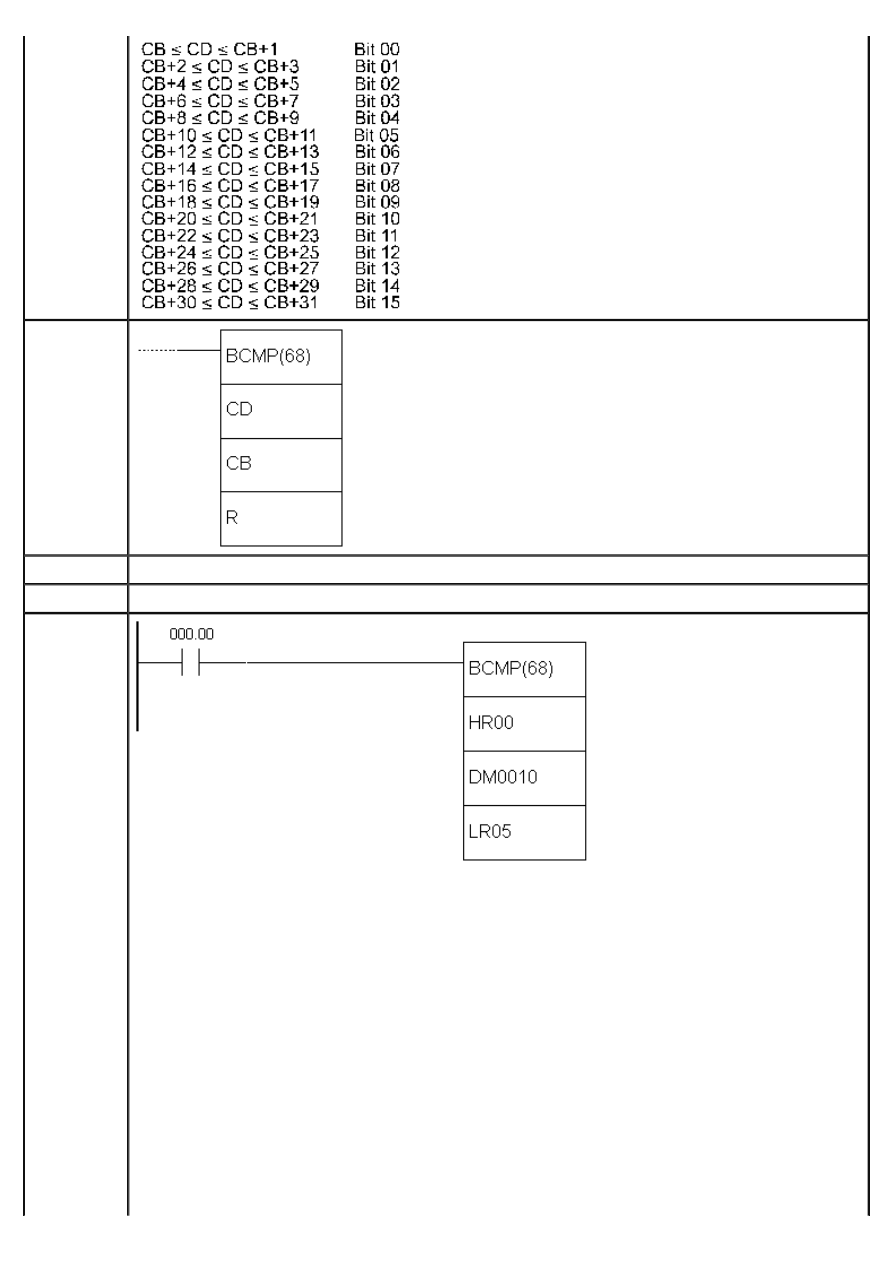
APPENDIX E - Ladder diagram instructions
Ladder
symbol
Limitations
Values of CB block must be in order, so that the value of location CB is lesser than value of CB+1.
Flag
It has no effect on any particular flag.
Example
Comparation will be executed for as long as the state of condition is ON. If value of location HR00
equals “0210”, then it will be set between DM0014 and DM0015 correspoding to the second bit of
the result word LR05.
http://www.mikroelektronika.co.yu/english/product/books/PLCbook/app_e/app_e1.htm (8 sur 32)05/11/2004 02:46:29
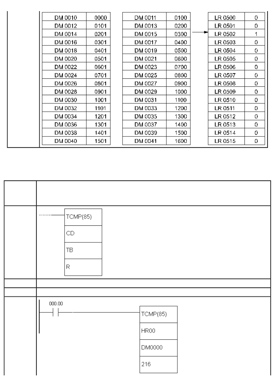
APPENDIX E - Ladder diagram instructions
E.27 TABLE COMPARE
- Table compare
Description
Instruction TCMP compares value of memory location CD with values of memory locations TB, TB+1,
TB+2, TB+3 ... TB+15. If value of location CB is equal to one of TB values, the appropriate bit of the
result word R is set. Based on this information, the programer knows which TB value matches the
value of location CD.
Ladder
symbol
Limitations
Locations DM 6144 - DM6655 cannot be used for the result word.
Flag
It has no effect on any particular flag.
Example
http://www.mikroelektronika.co.yu/english/product/books/PLCbook/app_e/app_e1.htm (9 sur 32)05/11/2004 02:46:29
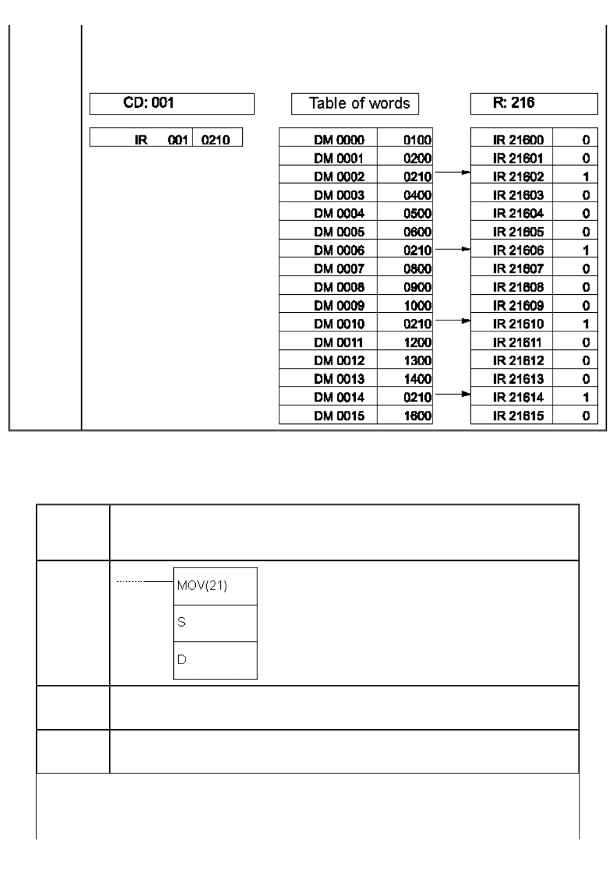
APPENDIX E - Ladder diagram instructions
Comparation will be executed as long as the state of bit IR000.00 is ON. If value of location HR00 is
“0210”, then it equals the values of locations DM0002, DM0006, DM0010 and DM0014. Accordingly,
the appropriate bits of the word IR216 change states to ON (they are set).
E.28 MOVE
- Moves the contents of one memory location to another
Description
Instruction MOVE is used for moving the contents of one memory location to another. The
operand S represents the word whose contents should be moved to a word that is
operand D. Operand S can be a constant, if the character “#” is placed ahead of four-digit
value.
Ladder
symbol
Limitations
Words DM6144 - DM6655 cannot be used as operand D. The current state of timer or
counter also cannot be used as operand D. Instruction BSET(17) should be used for that
purpose.
Flag
Flag EQ from TC area changes state to ON when all zeros are written into operand D.
Therefore, flag EQ provides us with information if the moved value equals zero. In case of
error, state of flag ER changes to ON.
http://www.mikroelektronika.co.yu/english/product/books/PLCbook/app_e/app_e1.htm (10 sur 32)05/11/2004 02:46:29
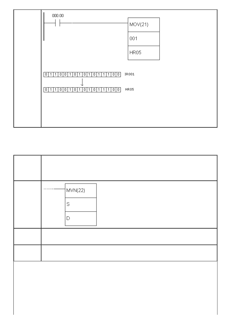
APPENDIX E - Ladder diagram instructions
Example
Upon fulfilling the condition on bit IR00.00, instruction moves the contents of memory
location IR001 to memory location HR05. Every bit of word IR001 is copied to the
appropriate bit of word HR05. Instruction MOV can be very helpful when reading the
signals controller sends or receives from peripheral devices. Input states are moved to a
working area, where they are processed and then they are sent to the output points of
PLC controller.
E.29 MOVE NOT
- Moves the complement
Description
Instruction MOVE NOT is used for moving the complemented (inverted bits, bit “0”
becomes “1”and vice versa) contents of one memory location to another. The operand S
represents the word whose complemented contents should be moved to a word that is
operand D. Operand S can be a constant, if the character “#” is placed ahead of four-digit
value.
Ladder
symbol
Limitations
Words DM6144 - DM6655 cannot be used as operand D. The current state of timer or
counter also cannot be used as operand D. Instruction BSET(17) should be used for that
purpose.
Flag
Flag EQ from TC area changes state to ON when all zeros are written into operand D.
Therefore, flag EQ provides us with information if the moved value equals zero. In case of
error, state of flag ER changes to ON.
http://www.mikroelektronika.co.yu/english/product/books/PLCbook/app_e/app_e1.htm (11 sur 32)05/11/2004 02:46:29
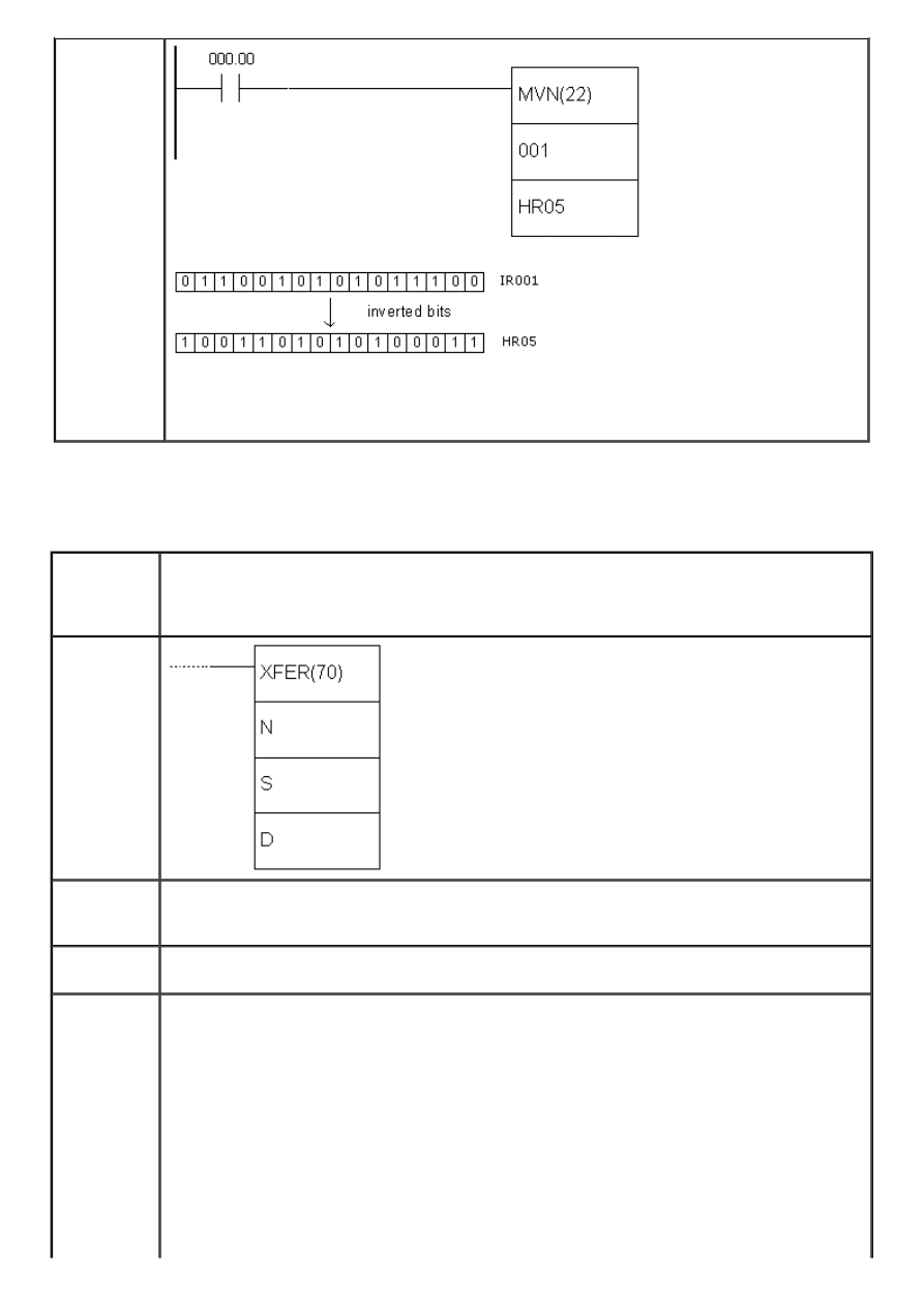
APPENDIX E - Ladder diagram instructions
Example
Upon fulfilling the condition on bit IR00.00, instruction moves the complemented contents
of memory location IR001 to memory location HR05. Every bit of word IR001 is
complemented and copied to the appropriate bit of word HR05.
E.30 BLOCK TRANSFER
- Copies one block of
words to another
Description
Instruction BLOCK TRANSFER copies the contents of one memory block of words to
another. Parametar “N” represents the number of memory locations copied, “S” is the
address of starting source memory location, while “D” represents the address of the
starting destination memory location.
Ladder
symbol
Limitations
Words DM6144 - DM6655 cannot be used as operand D. S and S+N have to be from the
same memory area. D and D+N also have to be from the same memory area. N has to be
a BCD number.
Flag
State of ER flag changes to ON if N is not a BCD number or in case that S and S+N, D and
D+N are not from the same memory area.
Example
http://www.mikroelektronika.co.yu/english/product/books/PLCbook/app_e/app_e1.htm (12 sur 32)05/11/2004 02:46:29
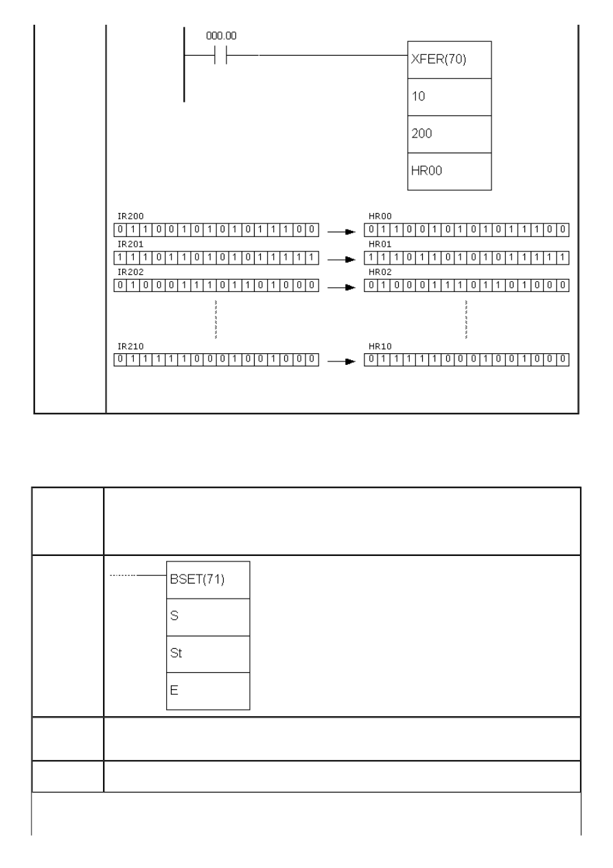
APPENDIX E - Ladder diagram instructions
Upon fulfilling the condition on bit IR00.00, instruction moves the contents of ten memory
locations IR200 - IR210 to memory locations HR00 - HR10.
E.31 BLOCK SET
- Copies the contents of one memory location to multiple locations
Description
Instruction copies the contents of one memory location S to a block of memory locations
from St to E. Parameter St contains the starting address of the block and parameter E
contains the ending address of the block. It is possible to change the contents of the
current timer/counter values with this instruction, unlike with instructions MOV and MVN.
Operand S can be a constant, if the character “#” is placed ahead of four-digit value.
Ladder
symbol
Limitations
Words DM6144 - DM6655 cannot be used as operands St and E. Address in the operand St
has to be lesser than the addreess in operand E. Both the operands St and E have to be
from the same memory block.
Flag
State of ER flag changes to ON if St and E do not belong to the same memory block or in
the case that the second parameter is greater than first.
http://www.mikroelektronika.co.yu/english/product/books/PLCbook/app_e/app_e1.htm (13 sur 32)05/11/2004 02:46:29
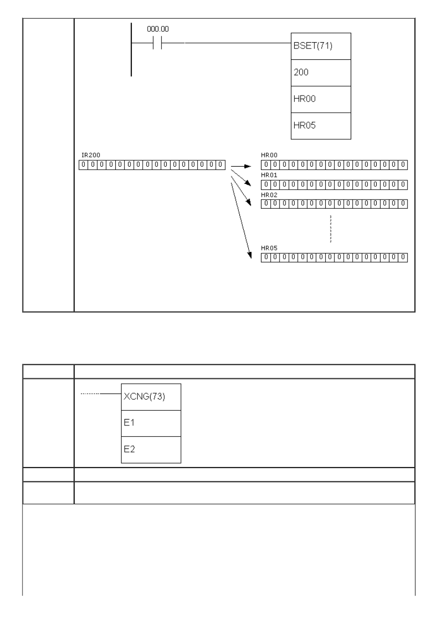
APPENDIX E - Ladder diagram instructions
Example
Upon fulfilling the condition on bit IR00.00, instruction moves the contents of memory
location IR000 (zero) to locations HR00 - HR05. In this way, it is possible to clear the
memory block or to set it to a certain value. Same effect could be achieved if constant
“#0000” was used instead of memory location IR200 containing all zeros.
E.32 DATA EXCHANGE
- Exchanges values of two memory locations
Description
Instruction exchanges the values of memory locations E and E1.
Ladder
symbol
Limitations
Words DM6144 - DM6655 cannot be used as operands E1 and E2.
Flag
State of ER flag changes to ON if non-existing indirect address of location from DM area is
used as an operand.
http://www.mikroelektronika.co.yu/english/product/books/PLCbook/app_e/app_e1.htm (14 sur 32)05/11/2004 02:46:29
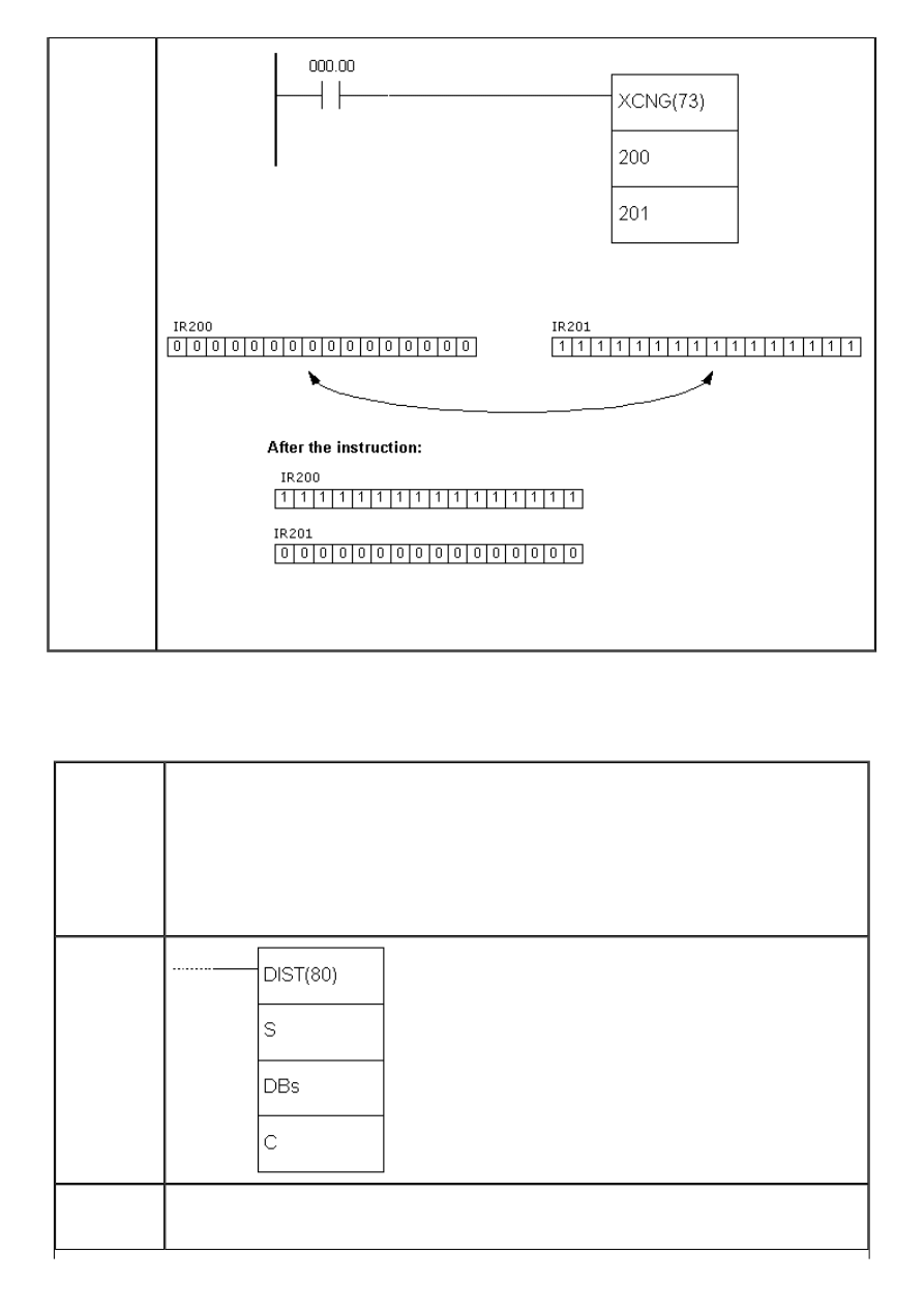
APPENDIX E - Ladder diagram instructions
Example
Upon fulfilling the condition on bit IR00.00 instruction exchanges the contents of memory
locations IR000 (all zeros) and IR201 (all ones). As a result, memory location IR201
contains all ones and memory location IR200 contains all zeros.
E.33 SINGLE WORD DISTRIBUTE
- Creates a stack
Description
Instruction can be used in two ways depending on the states of bits 12, 13, 14 and 15 of
memory location in parameter C. If these 4 bits have value between 0 and 8, then the
instruction copies the word from parameter S (or a constant if it is given with character
“#” ahead) to an address calculated by adding the base address from parameter DBs and
the shift defined in the rest of the word of parameter C.
When bits 12-15 in memory location of parameter C form the number 9, then the
instruction is used for stack operations. The rest of the value of word of parameter C now
defines number of the words in stack (from 000 to 999) and the contents of DBs
represent the stack pointer.
Ladder
symbol
Limitations
Words DM6144 - DM6655 cannot be used as operand DBs. Address of the operand DBs
has to be in the same memory block with BDs + shift. The argument C has to be BCD
number.
http://www.mikroelektronika.co.yu/english/product/books/PLCbook/app_e/app_e1.htm (15 sur 32)05/11/2004 02:46:29
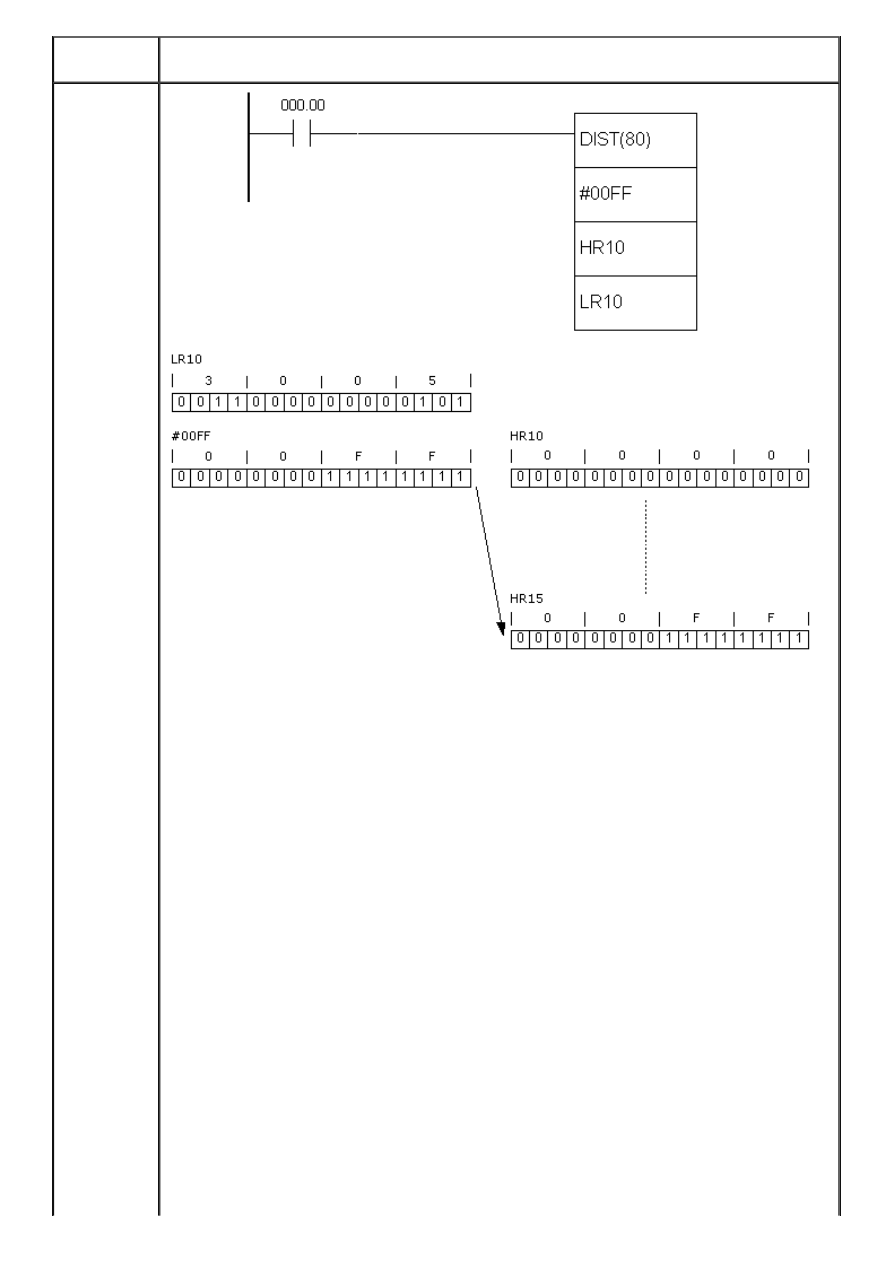
APPENDIX E - Ladder diagram instructions
Flag
EQ flag changes state to ON when the contents of memory location in parameter S equal
zero. State of ER flag changes to ON in case of error.
Examples
Bits 12-15 in the word LR10 from parameter C formthe number “0011”, which is in 0 - 8
range. Therefore, the instruction is used in the first form. Upon fulfilling the condition on
bit IR00.00, instruction copies the constant #00FF to an address calculated by adding the
base address (in this case HR10) and three lower numbers from the word LR10.
http://www.mikroelektronika.co.yu/english/product/books/PLCbook/app_e/app_e1.htm (16 sur 32)05/11/2004 02:46:29
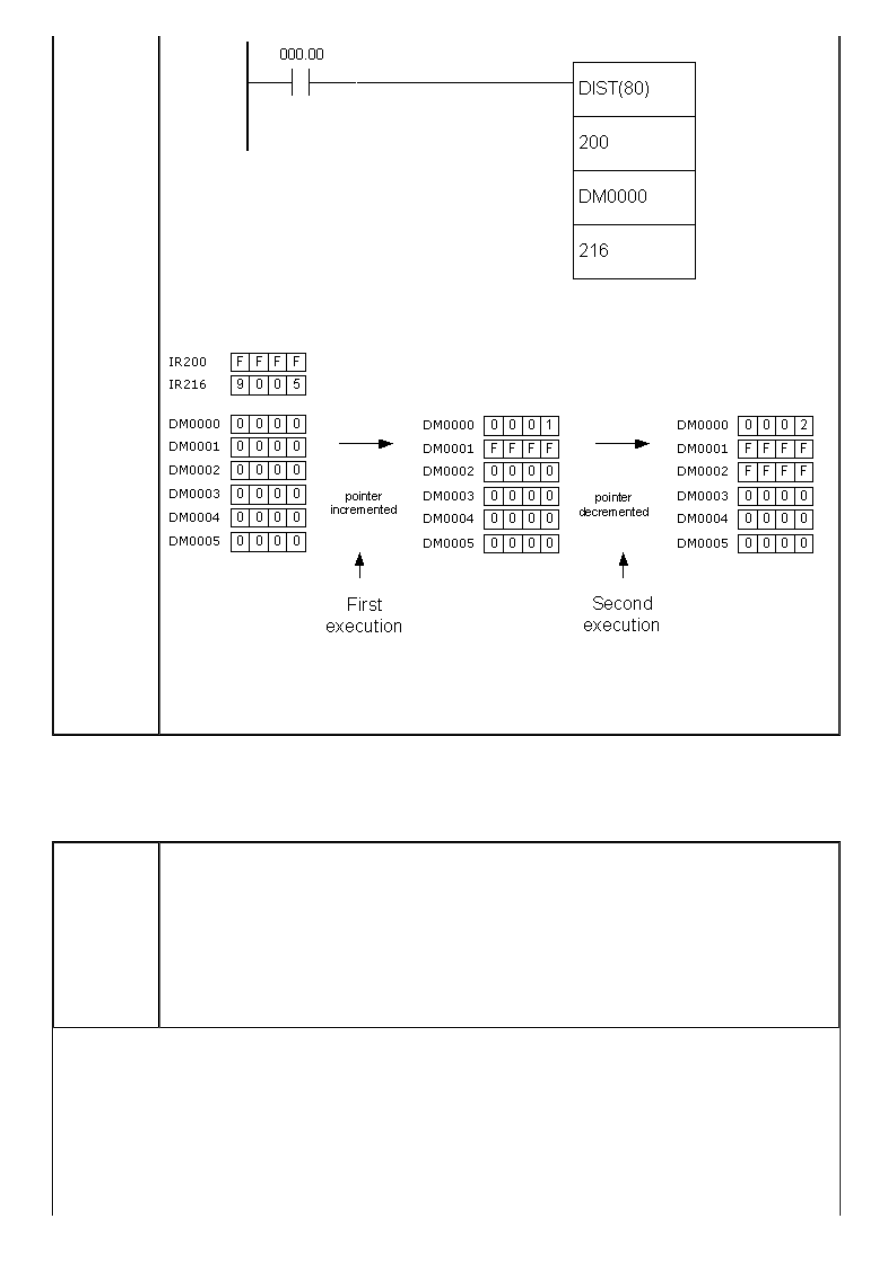
APPENDIX E - Ladder diagram instructions
Bits 12-15 in the word IR216 from parameter C form the number “0101”, which exceeds
8. Therefore, the instruction is used in the second form. The example above shows how
to create a stack between memory locations DM0001 and DM0005. Location DM0000 is
used as a pointer marking the top of the stack.
E.34 DATA COLLECT
- FIFO, LIFO stack
Description
Instruction can be used in three different ways depending on the states of bits 12-15 in
the word of parameter C:
1. If four bits have value between 0 and 7, the instruction copies the word D to an
address calculated by adding the address of the word SBs with the rest of the word C.
2. If value of four bits of word C equals 9, instruction creates the FIFO stack (First In First
Out). The rest of the bits of the word C determines the number of the words in stack (000
to 999), while SBs represents the pointer marking the top of the stack.
3. If value of four bits of word C equals 8, instruction creates the LIFO stack (Last In First
Out). The rest of the bits of the word C determine the number of the words in stack (000
to 999), while SBs represents the pointer marking the top of the stack.
http://www.mikroelektronika.co.yu/english/product/books/PLCbook/app_e/app_e1.htm (17 sur 32)05/11/2004 02:46:29
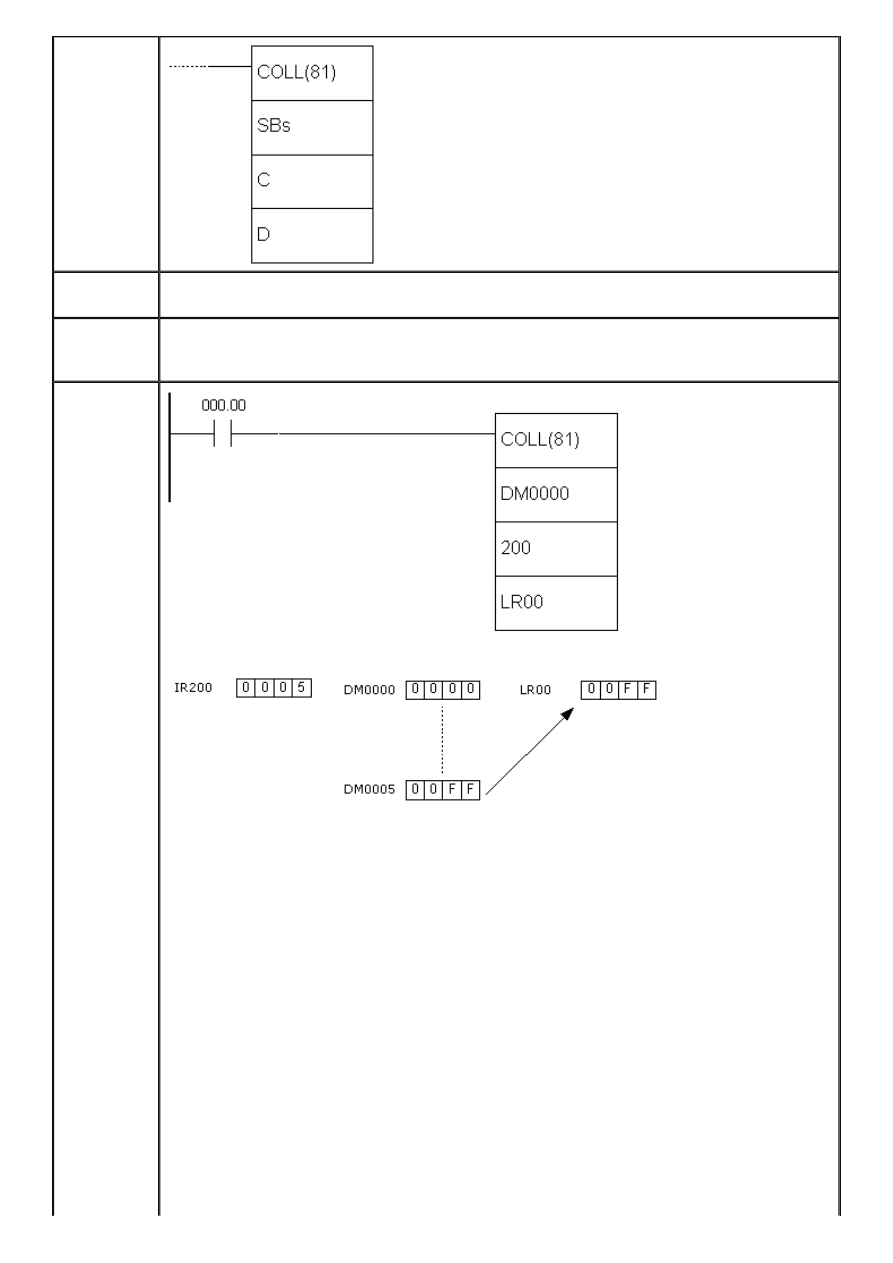
APPENDIX E - Ladder diagram instructions
Ladder
symbol
Limitations
Words DM6144 - DM6655 cannot be used as operand DBs. Parameter C has to be a BCD
number. SBs and SBs + shift have to be from the same memory block.
Flag
EQ flag changes state to ON when the contents of memory location in parameter S equal
zero. State of ER flag changes to ON in case of error, such as overflow or assigning non-
BCD contents to parameters S or D.
Examples
Bits 12 - 15 in the word IR200 form “0”, while the rest of the word forms value 005,
defining stack size to be 5 locations. Upon fulfilling the condition on bit IR000.00,
instruction copies the contents of word LR00 to an address calculated by adding the
address DM0000 with the shift defined in the word IR200 (lower three digits) : DM0000 +
005 = DM0005.
http://www.mikroelektronika.co.yu/english/product/books/PLCbook/app_e/app_e1.htm (18 sur 32)05/11/2004 02:46:29
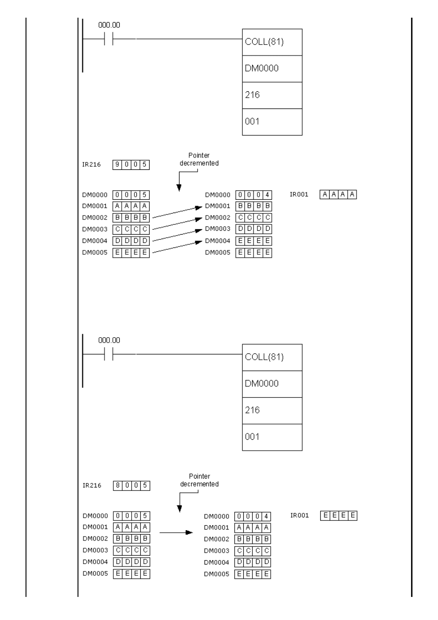
APPENDIX E - Ladder diagram instructions
Bits 12 - 15 in word IR216 form a number “9”, while the rest of the word forms value
005, defining the stack size to be 5 locations. Number “9” as the first digit of word IR216
determines that the instruction works with FIFO stack. Upon fulfilling the condition on bit
IR000.00, instruction moves the contents of the stack by one address, so that the
element that first came into the stack (“AAAA”) is copied to the word IR001, while the
stack pointer decreases by one.
http://www.mikroelektronika.co.yu/english/product/books/PLCbook/app_e/app_e1.htm (19 sur 32)05/11/2004 02:46:29
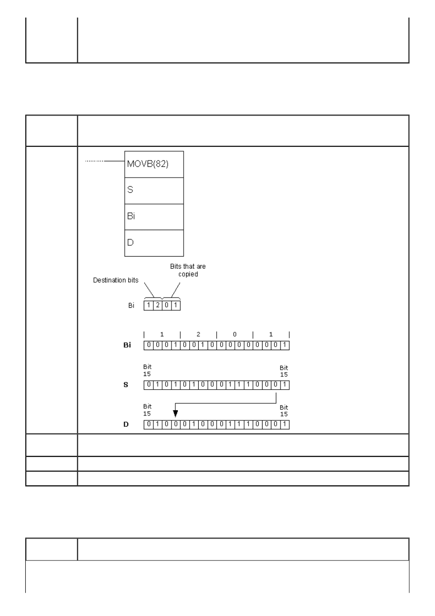
APPENDIX E - Ladder diagram instructions
Bits 12 - 15 of the word IR216 form a number “8”, while the rest of the word forms value
005, defining the stack size to be 5 locations. Number “8” as the first digit of the word
IR216 means that the instructions works with LIFO stack. Upon fulfilling the condition on
bit IR000.00, instruction copies the value of the last word that came into stack to the
location IR001, while the stack pointer decreases by one.
E.35 MOVE BIT
- Copies a bit from one word to another
Description
Instruction copies a specified bit from the word S to a specified bit of word D. The word Bi
determines the positions of bits in question. The upper 2 digits determine the destination
bit, while lower 2 determine the source bit.
Ladder
symbol
Limitations
Values of destination and source bits has to be between 0 and 15. Words DM6144 -
DM6655 cannot be used as operands Bi or D.
Flag
Example
E.36 MOVE DIGIT
- Moves a digit from one word to another
Description
Instruction copies a specified digit from the word S to a specified digit of the word D. The
word Di determines the positions of digits in question.
http://www.mikroelektronika.co.yu/english/product/books/PLCbook/app_e/app_e1.htm (20 sur 32)05/11/2004 02:46:29
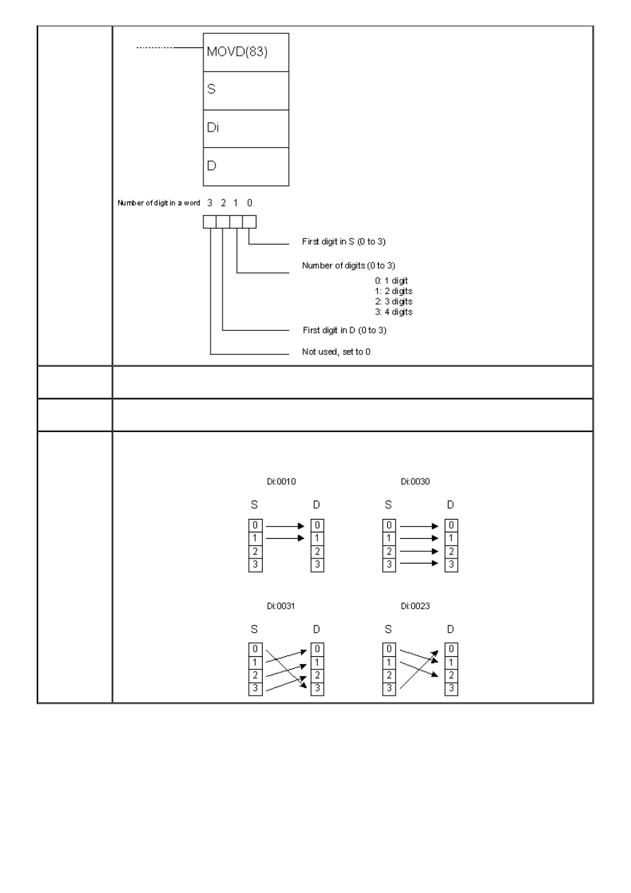
APPENDIX E - Ladder diagram instructions
Ladder
symbol
Limitations
Value of destination and source bit has to be between 0 and 15. Words DM6144 -
DM6655 cannot be used as operands Bi or D.
Flag
ER flag changes state to ON if at least one of three digits in the word Di isn’t in the
specified range (between 0 and 3).
Example
The examples below show copying digits from one word to another depending on the
value of word Di.
E.37 SHIFT REGISTER
- Shifts the contents of a word for 1 bit to the left
http://www.mikroelektronika.co.yu/english/product/books/PLCbook/app_e/app_e1.htm (21 sur 32)05/11/2004 02:46:29
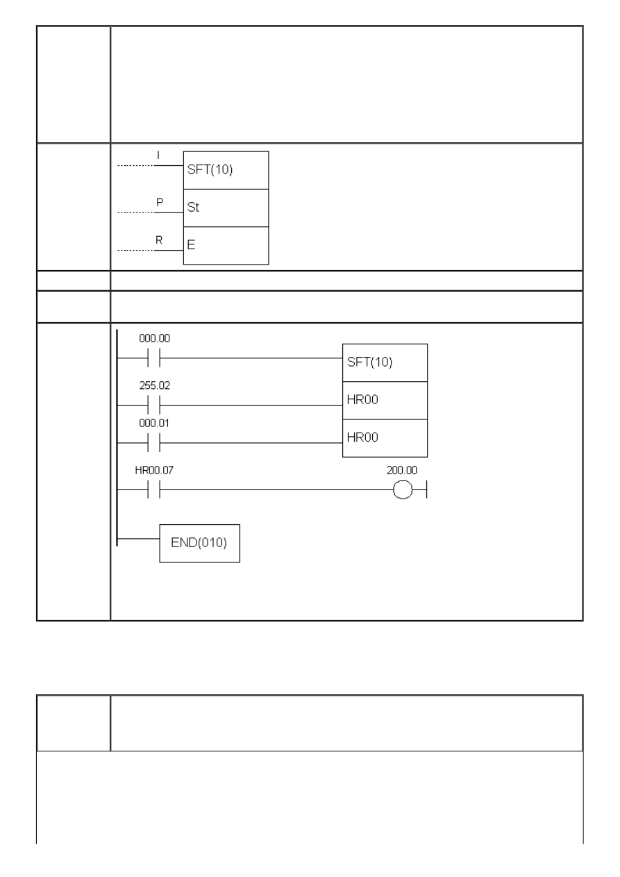
APPENDIX E - Ladder diagram instructions
Description
Instruction shifts the contents of word St for 1 bit to the left. The highest bit of the word
St moves to the place of the lowest bit in the word St+1, the highest bit of the word St+1
moves to the position of the lowest bit in the word St+2 and so forth, up to the word E.
The highest bit of the word E is irreversibly lost with every shifting. Input I defines
whether “0” or “1” fills the lowest bit position. If the state of I line is ON, value is one,
while OFF defines zero. Input P is used as clock for the instruction and switching it from
OFF to ON changes the bit shift. State on R line can be OFF when the instruction can be
executed and ON when all the bits within word range from St to E are set to “0”. As long
as the state of R line isn’t set to OFF state, instruction cannot be executed.
Ladder
symbol
Limitations
E has to be greater or equal to the address in parameter St.
Flag
ER flag changes state to ON if St is lower address than E or if they are not in the same
memory area.
Example
Upon fulfilling the condition on bit IR000.00, instruction uses one-second clock on bit
255.02 in order to move the contents of the word HR00. Bit IR200.00 will be ON every
time the bit HR00.07 equals one.
E.38 WORD SHIFT
- Shifts whole words
Description
Instruction shifts the whole contents of the word St to an address greater by one than the
current. Value of the word from the parameter St is moved to St+1 up to the the word
defined with parameter E. Word that equals zero fills the place on the right for every
shifting. Value of the word on the address from parameter E is irreversibly lost.
http://www.mikroelektronika.co.yu/english/product/books/PLCbook/app_e/app_e1.htm (22 sur 32)05/11/2004 02:46:29
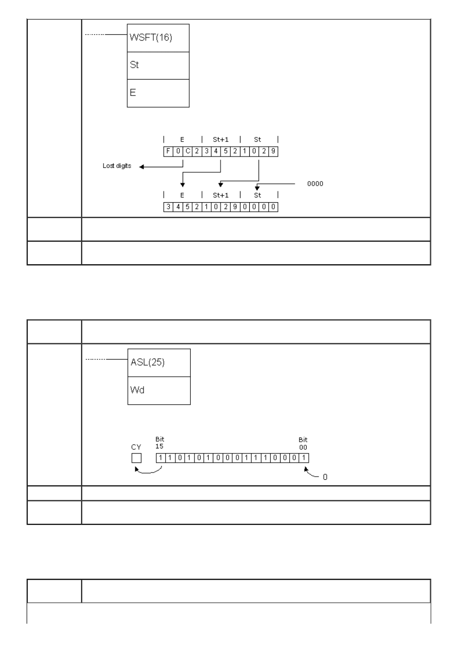
APPENDIX E - Ladder diagram instructions
Ladder
symbol
Limitations
E has to be greater or equal address to the one from parameter St. Words DM6144 -
DM6655 cannot be used as operands St and E.
Flag
ER flag changes state to ON if St is lower address than E or if they are not from the same
memory area.
E.39 ARITHMETIC SHIFT LEFT
- Arithmetic shift left
Description
Instruction shifts the contents of the word Wd for one bit to the left. The lowest bit
becomes “0”, while the highest bit is moved to carry bit.
Ladder
symbol
Limitations
Words DM6144 - DM6655 se ne mogu koristiti za operand Wd.
Flag
EQ flag changes state to ON if the contents of the word Wd equal zero. CY flag takes the
value of the highest bit of theword Wd and changes state accordingly.
E.40 ARITHMETIC SHIFT RIGHT
- Arithmetic shift right
Description
Instruction shifts the contents of the word Wd for 1 bit to the right. The highest bit takes
value “0”, while the lowest bit moves to carry bit (CY).
http://www.mikroelektronika.co.yu/english/product/books/PLCbook/app_e/app_e1.htm (23 sur 32)05/11/2004 02:46:29
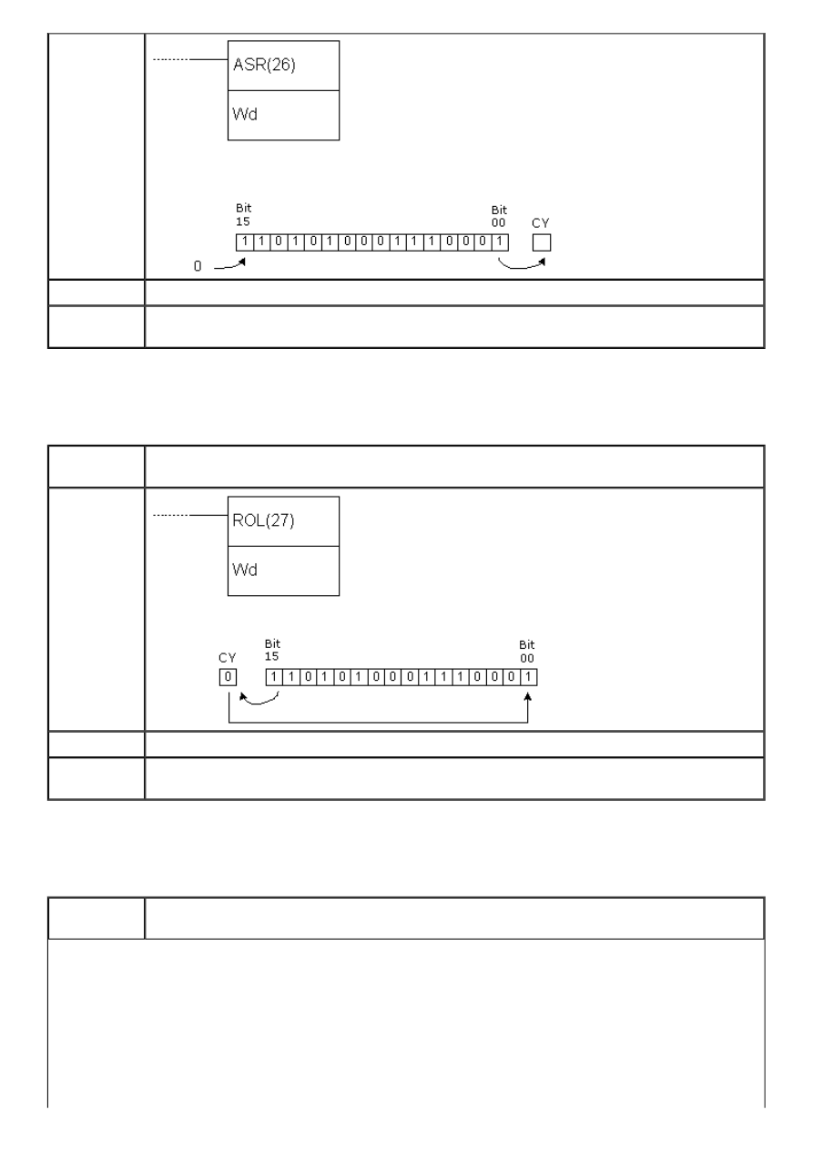
APPENDIX E - Ladder diagram instructions
Ladder
symbol
Limitations
Words DM 6144 - DM6655 cannot be used as operand Wd.
Flag
EQ flag changes state to ON if the contents of the word Wd equal zero. CY flag takes the
value of the lowest bit of the word Wd and changes state accordingly.
E.41 ROTATE LEFT
- Rotates the contents of a word for 1 bit to the left
Description
Instruction shifts the contents of the word Wd for one bit to left, using the carry bit CY.
Bit from CY is then moved to the lowest bit to close the circle.
Ladder
symbol
Limitations
Word DM6144 - DM6655 cannot be used as operand Wd.
Flag
EQ flag changes state to ON if the contents of the word Wd equal zero. CY flag takes
value of the highest bit of the word Wd and changes state accordingly.
E.42 ROTATE RIGHT
- Rotates the contents of a word for 1 bit to the right
Description
Instruction shifts the contents of the word Wd for one bit to the right, using the carry bit
CY. Bit from CY is then moved to the highest bit to close the circle.
http://www.mikroelektronika.co.yu/english/product/books/PLCbook/app_e/app_e1.htm (24 sur 32)05/11/2004 02:46:29
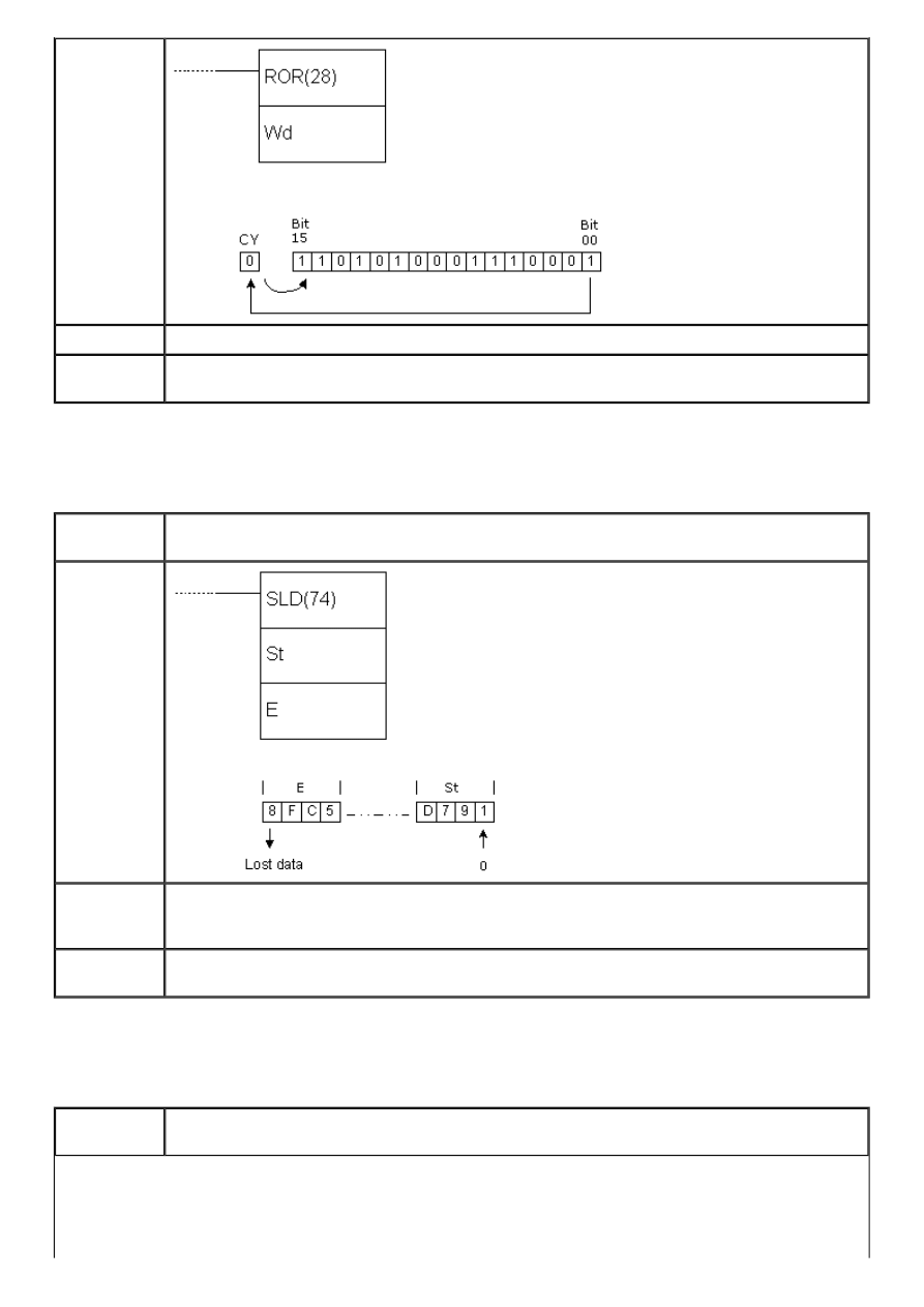
APPENDIX E - Ladder diagram instructions
Ladder
symbol
Limitations
Word DM6144 - DM6655 cannot be used as operand Wd.
Flag
EQ flag changes state to ON if the contents of the word Wd equal zero. CY flag takes
value of the lowest bit of the word Wd and changes state accordingly.
E.43 ONE DIGIT SHIFT LEFT
- Shifts word for one digit to the left
Description
Instruction shifts the contents of the word St for one digit to the left. The highest digit of
the word E is irreversably lost and the lowest digit of the word St takes zero value.
Ladder
symbol
Limitations
Words DM 6144 - DM6655 cannot be used as operands St and E. Operands St and E have
to be in the same memory area, while the address of operand E has to be greater or
equal to the address of operand St.
Flag
ER flag changes state to ON if St and E are not from the same memory area or in case
that the address of parameter E is lower than the address of parameter St.
E.44 ONE DIGIT SHIFT RIGHT
- Shifts word for one digit to the right
Description
Instruction shifts the contents of the word St for one digit to the right. The lowest digit of
the word E is irreversably lost and the lowest digit of the word St takes zero value.
http://www.mikroelektronika.co.yu/english/product/books/PLCbook/app_e/app_e1.htm (25 sur 32)05/11/2004 02:46:29
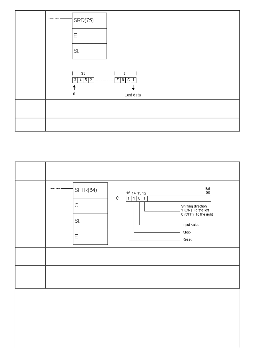
APPENDIX E - Ladder diagram instructions
Ladder
symbol
Limitations
Words DM 6144 - DM6655 cannot be used as operands St and E. Operands St and E have
to be in the same memory area and the address of the operand E has to be lower or
equal to the address of the operand St.
Flag
ER flag changes state to ON if St and E are not from the same memory area or in case
that the address of parameter E is higher than the address of parameter St.
E.45 REVERSIBLE SHIFT REGISTER
- Shifts words to the left or to the right
Description
Instruction is used for shifting one or several words in both directions, according to the
states of the highest 4 bits in the control word C. The control word determines shifting
direction, input value, clock and reset input.
Ladder
symbol
Limitations
Words DM 6144 - DM6655 cannot be used as operands C, St and E. Operands St i E have
to be from the same memory area and the address of the operand St has to be lower or
equal to the address of the operand E.
Flag
ER flag changes state to ON if St and E are not from the same memory area or the
address of parameter St is higher than the address of parameter E. CY changes according
to the state of the lowest bit of the word St or the highest bit of the word E, depending on
the shifting direction set in the control word C.
http://www.mikroelektronika.co.yu/english/product/books/PLCbook/app_e/app_e1.htm (26 sur 32)05/11/2004 02:46:29
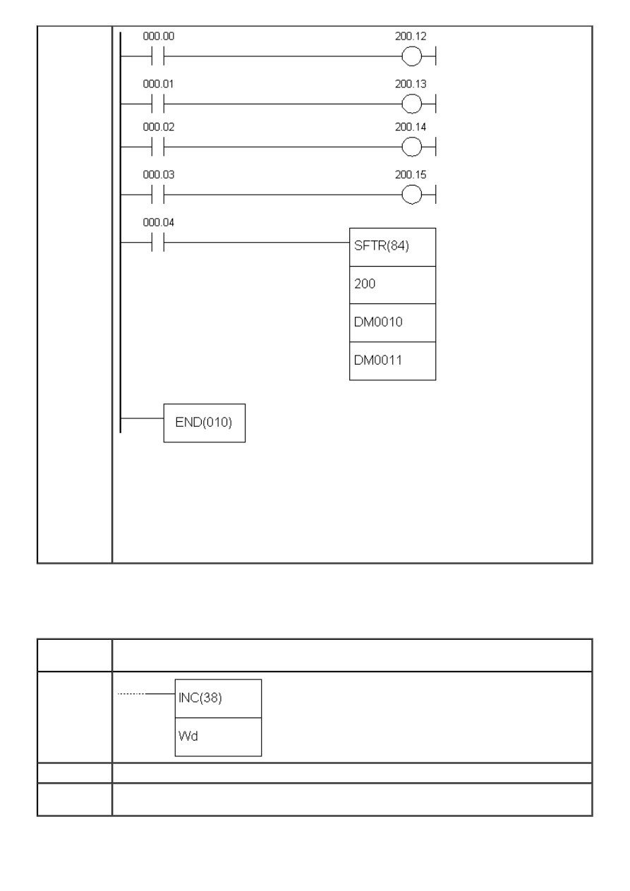
APPENDIX E - Ladder diagram instructions
Example
First instruction line determines the shifting direction, second determines input, third
determines the clock and fourth determines reset. The shifting direction depends on the
bit 12 of the control word. Depending on it, data bit moves to CY carry bit, while the
opposite end becomes “0” or “1” depending on bit 13 of the control word. Condition for
executing this instruction is located in the bit IR000.04, but besides this it is necessary to
have the clock (bit 14 of the control word) ON. If the instruction is being executed with
reset bit (bit 15 of the control word) OFF, all data bits as well as carry bit CY are set to
“0”.
E.46 BCD INCREMENT
- Increases the contents of a word by 1
Description
Instruction increases the contents of the word Wd by one when the condition is fulfilled.
Incrementation does not affect the carry bit.
Ladder
symbol
Limitations
Words DM 6144 - DM6655 cannot be used as operand Wd.
Flag
ER flag changes state to ON if the contents of the word Wd are not BCD.
EQ flag changes state to ON when the result of incrementation equals “0”.
http://www.mikroelektronika.co.yu/english/product/books/PLCbook/app_e/app_e1.htm (27 sur 32)05/11/2004 02:46:29
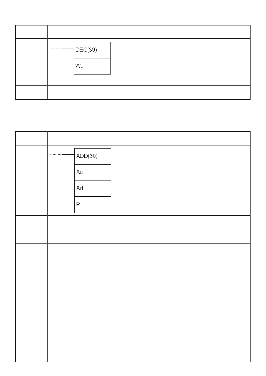
APPENDIX E - Ladder diagram instructions
E.47 BCD DECREMENT
- Decreases the contents of a word by 1
Description
Instruction decreases the contents of the word Wd by one when the condition is fulfilled.
Decrementation does not affect the carry bit.
Ladder
symbol
Limitations
Words DM6144 - DM6655 cannot be used as operand Wd.
Flag
ER flag changes state to ON if the contents of the word Wd are not BCD.
EQ flag changes state to ON when the result of decrementation equals “0”.
E.48 BCD ADD
- Adds two values
Description
Instruction adds the contents of words Au and Ad (Au + Ad + CY) and stores the result in
location R. If the result is greater than 9999 carry bit CY is set.
Ladder
symbol
Limitations
Words DM6144 - DM6655 cannot be used as operand R.
Flag
ER flag changes state to ON if the contents of words Au and Ad are not BCD.
EQ flag changes state to ON if the result equals “0”.
CY flag changes state to ON if the result is greater than 9999.
Example
Upon fulfilling the condition on bit IR000.02, carry bit is cleared and the value of memory
location IR200 is added to the constant 6103. The result is stored in the memory location
DM0100. The example further shows how to save the carry bit if the result was greater
than 9999. If the result exceeded 9999, memory location DM0101 will take value “1” and
if not it will take value “0”. In this way, locations DM0100 and DM0101 form one 32-bit
word, which may prove to be useful.
http://www.mikroelektronika.co.yu/english/product/books/PLCbook/app_e/app_e1.htm (28 sur 32)05/11/2004 02:46:29
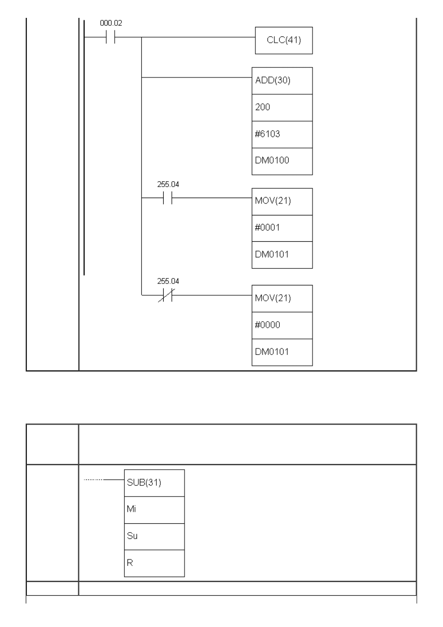
APPENDIX E - Ladder diagram instructions
E.49 SUBTRACT
- Subtracts two values
Description
Instruction subtracts the contents of the word Su and a value of carry bit CY from the
contents of the word Mi. The result is stored in the memory location R If the result is
negative, carry bit CY is set and a 10’complement of the result is stored into R. To get the
real result, just subtract the value in R from zero.
Ladder
symbol
Limitations
Words DM 6144 - DM6655 cannot be used as operand R.
http://www.mikroelektronika.co.yu/english/product/books/PLCbook/app_e/app_e1.htm (29 sur 32)05/11/2004 02:46:29
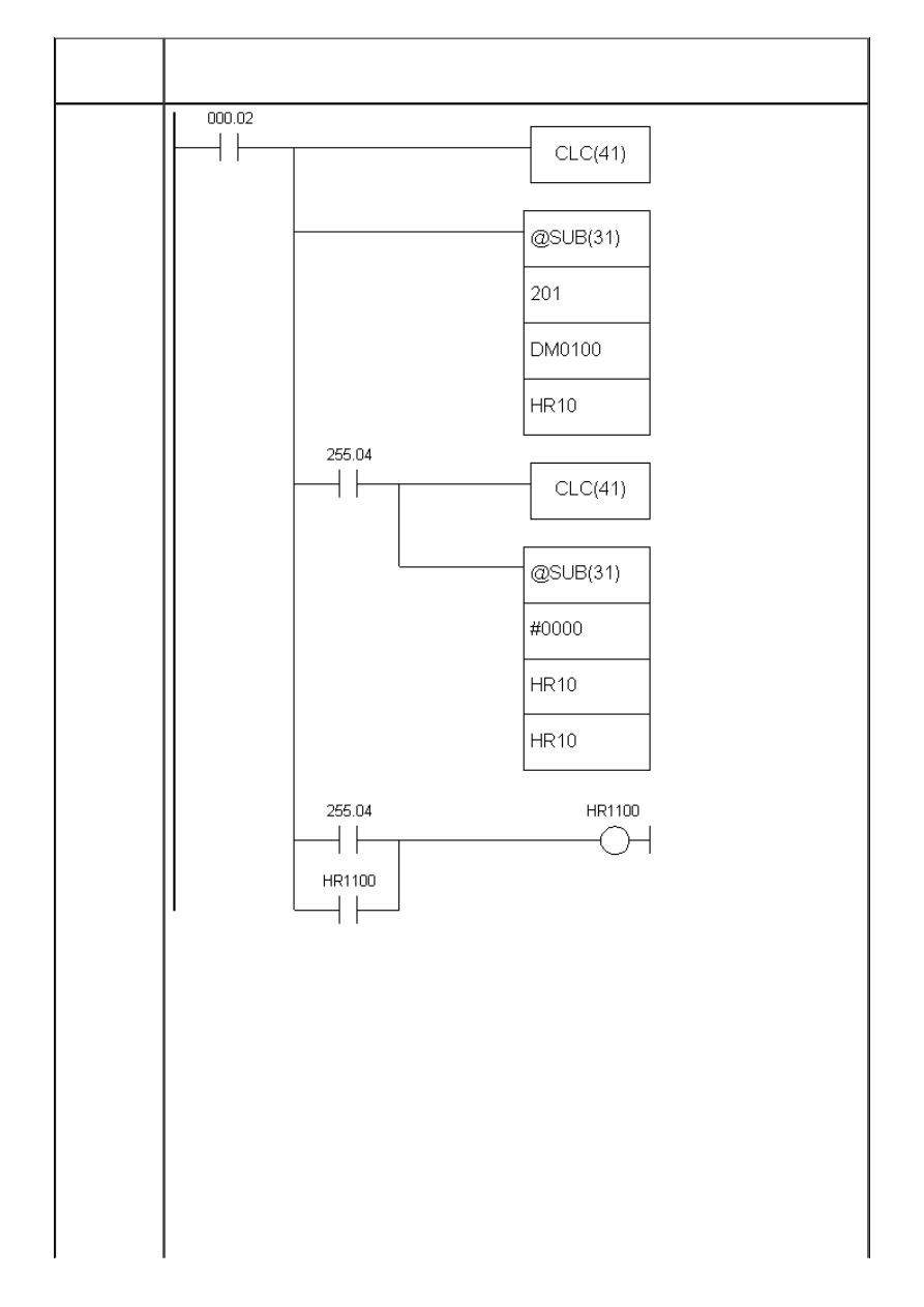
APPENDIX E - Ladder diagram instructions
Flag
ER flag changes state to ON if the contents of words Mi and Su are not BCD.
EQ flag changes state to ON if the result equals “0”.
CY flag changes state to ON if the result is negative.
Example
Carry bit status should be checked before the subtraction. It is best to clear it with CLC
instruction. The check is more necessary after the subtraction, because there is chance of
misinterpretation. If the carry bit is set (value is “1”) the result of subtraction is negative
and the result word contains 10’ complement of the real result.
When the condition is fulfilled on bit IR000.02, carry bit is cleared and the value of
memory location DM0100 is subtracted from value of location IR201. The result is stored
in the location HR10. Upon subtraction, carry bit CY is checked. If it is set, condition on
SR255.04 (the very carry bit) will be fulfilled, clearing it anew and commencing the new
subtraction in order to get the real result of the first subtraction. The second subtraction
instruction subtracts the value of the result word HR10 from zero, storing the result into
HR10 again.
It is useful to set a certain bit for a programmer to have information on negative result.
In the following example this bit is HR1100. Changing the state of carry bit to OFF doesn’t
change the state of bit HR1100.
http://www.mikroelektronika.co.yu/english/product/books/PLCbook/app_e/app_e1.htm (30 sur 32)05/11/2004 02:46:29
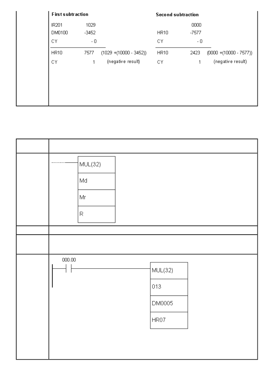
APPENDIX E - Ladder diagram instructions
Character “@” ahead of SUB(31) represents the differencial form of the instruction, or
simply put, this instruction will not execute non-stop while the condition is fulfilled. Only
changing the condition from OFF to ON executes the instruction. This means that the
second subtraction instruction won’t take place immediately after the first one. Before
executing the second instruction, it is necessary that bit IR000.02 changed state from
OFF to ON at least once.
E.50 BCD MULTIPLY
- Multiplies two values
Description
Instruction multiplies values of locations Md and Mr and stores the result into memory
locations R and R+1.
Ladder
symbol
Limitations
Words DM6144 - DM6655 cannot be used as operand R.
Flag
ER flag changes state to ON if the contents of words Mr and Md are not BCD.
EQ flag changes state to ON if the result equals “0”.
CY flag changes state to ON if the there is a carry in the result.
Example
Upon fulfilling the condition on bit IR000.00, instruction multiplies the values of memory
locations IR013 and DM0005. The result is stored into two sequential memory locations
HR07 and HR08. The result is stored so that HR08 contains higher bits and that HR07
contains lower bits.
http://www.mikroelektronika.co.yu/english/product/books/PLCbook/app_e/app_e1.htm (31 sur 32)05/11/2004 02:46:29

APPENDIX E - Ladder diagram instructions
© C o p y r i g h t 2 0 0 3. m i k r o E l e k t r o n i k a. All Rights Reserved. For any comments contact
.
http://www.mikroelektronika.co.yu/english/product/books/PLCbook/app_e/app_e1.htm (32 sur 32)05/11/2004 02:46:29
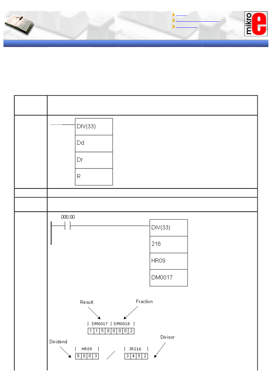
APPENDIX E - Ladder diagram instructions
Introduction to PLC controllers
on-line
FREE
!
Index
Development systems
Contact us
APPENDIX E
Ladder diagram instructions
(3/3)
E.51 BCD DIVIDE
- Divides two values
Description
Instruction divides the contents of location Dd with contents of location Dr. The result of
division is stored in locations R and R+1. The first contains the rounded off result of
division, while R+1 contains the fraction.
Ladder
symbol
Limitations
Words DM6144 - DM6655 cannot be used as operand R.
Flag
ER flag changes state to ON if the contents of words Dd and Dr are not BCD.
EQ flag changes state to ON if the result equals “0”.
Example
http://www.mikroelektronika.co.yu/english/product/books/PLCbook/app_e/app_e2.htm (1 sur 35)05/11/2004 02:48:36
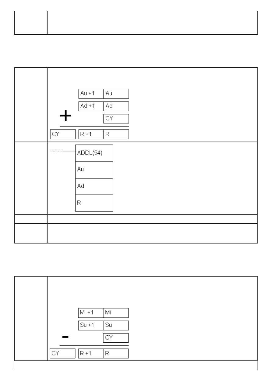
APPENDIX E - Ladder diagram instructions
Upon fulfilling the condition on bit IR000.00, instruction divides the value of memory
location IR216 by the value of memory location HR09. The result is stored into two
sequential memory locations DM0017 and DDM0018. The result is stored so that DM0017
contains round number and DM0018 contains the fraction.
E.52 DOUBLE BCD ADD
- Adds two 32-bit words
Description
Instruction adds values from addresses Au and Au+1 to values from addresses Ad, Ad+1
and carry bit CY. If the result exceeds 99999999 carry bit CY is set.
Ladder
symbol
Limitations
Word DM6144 - DM6655 cannot be used as operand R.
Flag
ER flag changes state to ON if the contents of words Au and Ad are not BCD.
EQ flag changes state to ON if the result equals “0”.
CY flag changes state to ON if there is a carry in the result.
E.53 DOUBLE BCD SUBTRACT
- Subtracts two 32-bit words
Description
Instruction subtracts the contents of two words Su+1 and Su with carry bit CY added
from the contents of words Mi+1 and Mi. The result is stored into memory locations R+1
and R. If the result is negative, carry bit CY is set and 10’complement of the result is
stored into R. To get the real result, contents of R should be subtracted from zero.
http://www.mikroelektronika.co.yu/english/product/books/PLCbook/app_e/app_e2.htm (2 sur 35)05/11/2004 02:48:36
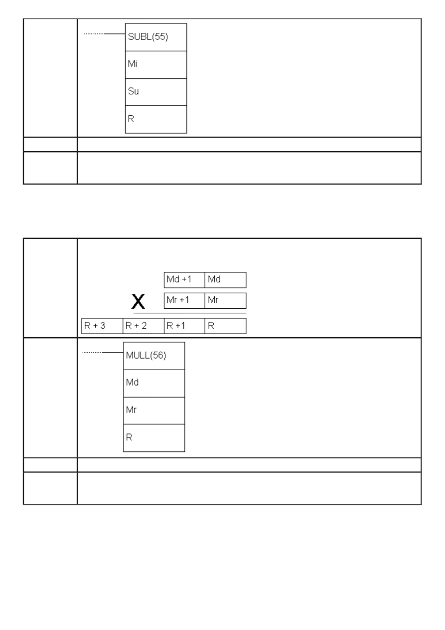
APPENDIX E - Ladder diagram instructions
Ladder
symbol
Limitations
Words DM6144 - DM6655 cannot be used as operand R.
Flag
ER flag changes state to ON if the contents of words Mi, Mi+1, Su, Su+1 are not BCD.
EQ flag changes state to ON if the result equals “0”.
CY flag changes state to ON if the result is negative.
E.54 DOUBLE BCD MULTIPLY
- Multiplies two pairs of words
Description
Instruction multiplies values of locations Md, Md+1 with the values of locations Mr, Mr+1.
The result is stored into 4 locations: R, R+1, R+2 i R+3.
Ladder
symbol
Limitations
Words DM6144 - DM6655 cannot be used as operand R.
Flag
ER flag changes state to ON if the contents of words Mr, Mr+1, Md and Md+1 are not BCD.
EQ flag changes state to ON if the result equals “0”.
CY flag changes state to ON if there is a carry in the result.
E.55 DOUBLE BCD DIVIDE
- Divides two pairs of words
http://www.mikroelektronika.co.yu/english/product/books/PLCbook/app_e/app_e2.htm (3 sur 35)05/11/2004 02:48:36
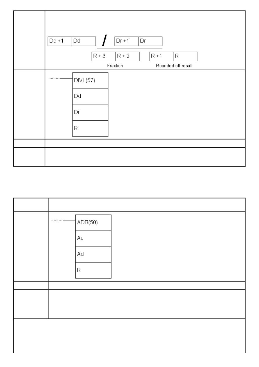
APPENDIX E - Ladder diagram instructions
Description
Instruction divides the contents of locations Dd, Dd+1 by the contents of locations Dr i Dr
+1. The result is stored into locations R and R+1 while locations R+2 and R+3 contain
the fraction.
Ladder
symbol
Limitations
Words DM6144 - DM6655 cannot be used as operand R.
Flag
ER flag changes state to ON in two cases, if the contents of words Dd, Dd+1, Dr and Dr
+1 are not BCD or if the contents of locations Dr and Dr+1 equal zero.
EQ flag changes state to ON if the result equals “0”.
E.56 BINARY ADD
- Binary addition
Description
Instruction executes binary addition of words Au and Ad with carry bit and stores the
result into memory location R. If the result is greater than FFFF the carry bit CY is set.
Ladder
symbol
Limitations
Words DM 6144 - DM6655 cannot be used as operand R.
Flag
ER flag changes state to ON in case of error.
EQ flag changes state to ON if the result equals “0”.
CY flag changes state to ON if the result is greater FFFF.
OF flag changes state if the result is greater than +32.767 (7FFF).
UF flag changes state if the result is lower than od +32.768 (7FFF).
http://www.mikroelektronika.co.yu/english/product/books/PLCbook/app_e/app_e2.htm (4 sur 35)05/11/2004 02:48:36
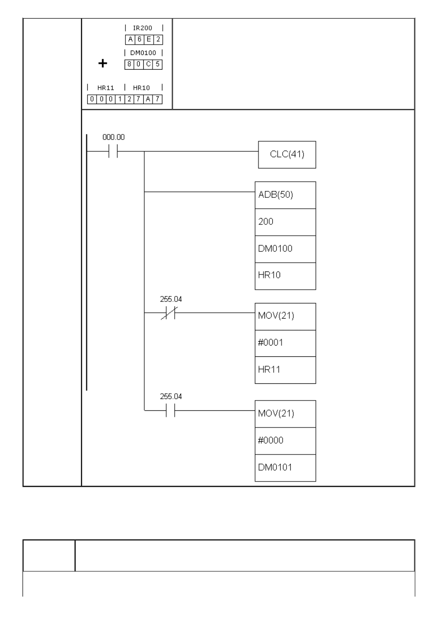
APPENDIX E - Ladder diagram instructions
Example
The example demonstrates how the binary addition works. As
A6E2+80C5 equals 127A7, carry bit CY is set and the value of
location R+1 (which is, in this case, on HR11) changes to “1” to
enable easier handling of the result on addresses R and R+1
later in the program. If overflow occurs, carry bit CY will be set,
fulfilling the condition on bit SR255.04. This condition controls
the lower MOV instruction, which sets “1” to location HR11.
E.57 BINARY SUBTRACT
- Binary subtraction
Description
Instruction subtracts values Su+CY from the value Mi and stores the result into location
R. If the result is negative, carry bit CY is set and the 2’complement of the real result is
stored into location R.
http://www.mikroelektronika.co.yu/english/product/books/PLCbook/app_e/app_e2.htm (5 sur 35)05/11/2004 02:48:36
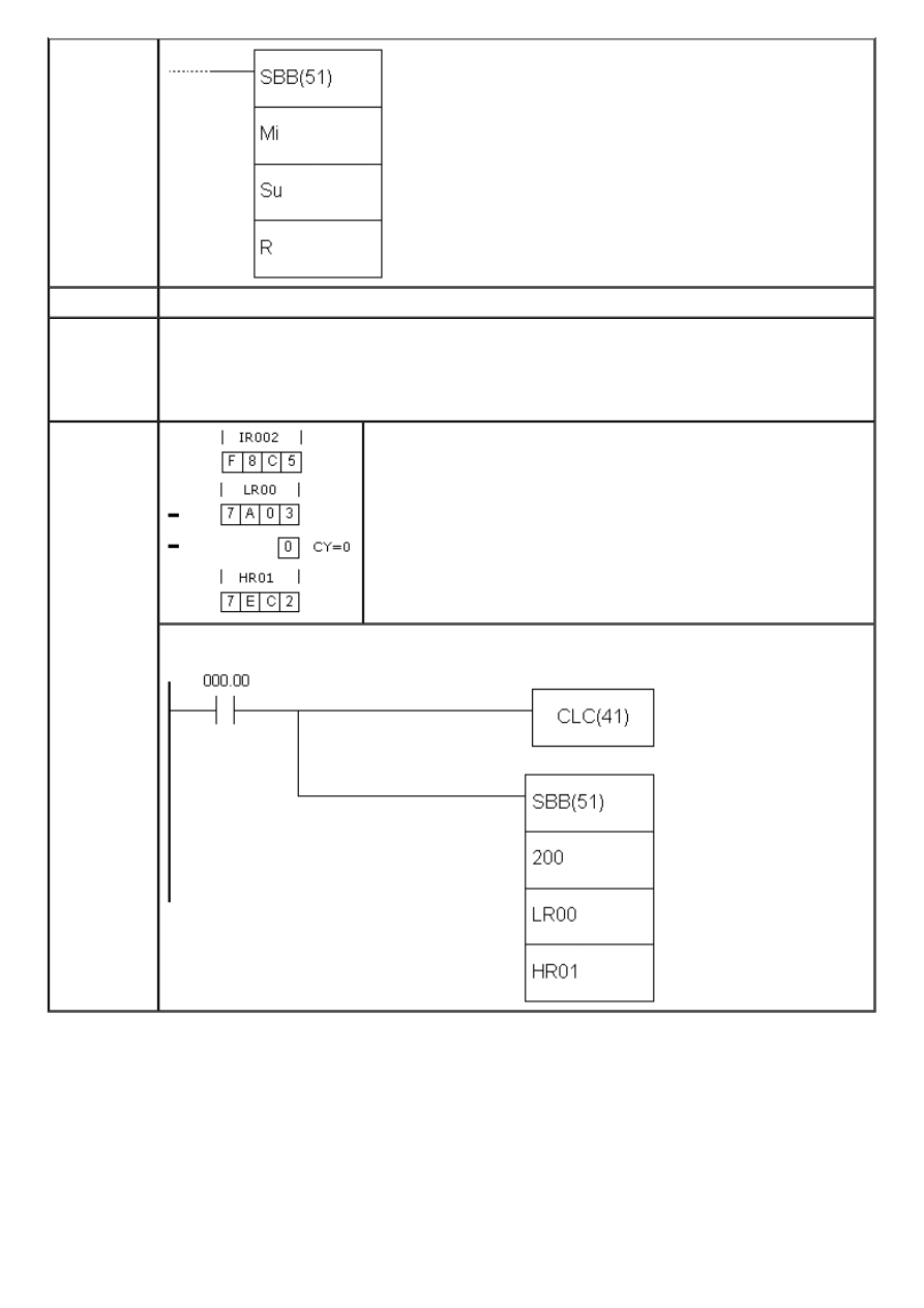
APPENDIX E - Ladder diagram instructions
Ladder
symbol
Limitations
Words DM6144 - DM6655 cannot be used as operand R.
Flag
ER flag changes state to ON in case of error.
EQ flag changes state to ON if the result equals “0”.
CY flag changes state to ON if the result is negative.
OF flag changes state if the result is greater than +32.767 (7FFF)
UF flag changes state if the result is lower than +32.768 (7FFF).
Example
The example subtracts the value of location LR00 increased by
the state of carry bit CY from the value of location IR200. As
the result is positive, carry bit CY will not be set. In case of
negative result, location HR01 would contain 2’complement of
the result, so that a conversion would be necessary for getting
the real result.
E.58 BINARY MULTIPLY
- Binary multiplication
http://www.mikroelektronika.co.yu/english/product/books/PLCbook/app_e/app_e2.htm (6 sur 35)05/11/2004 02:48:36
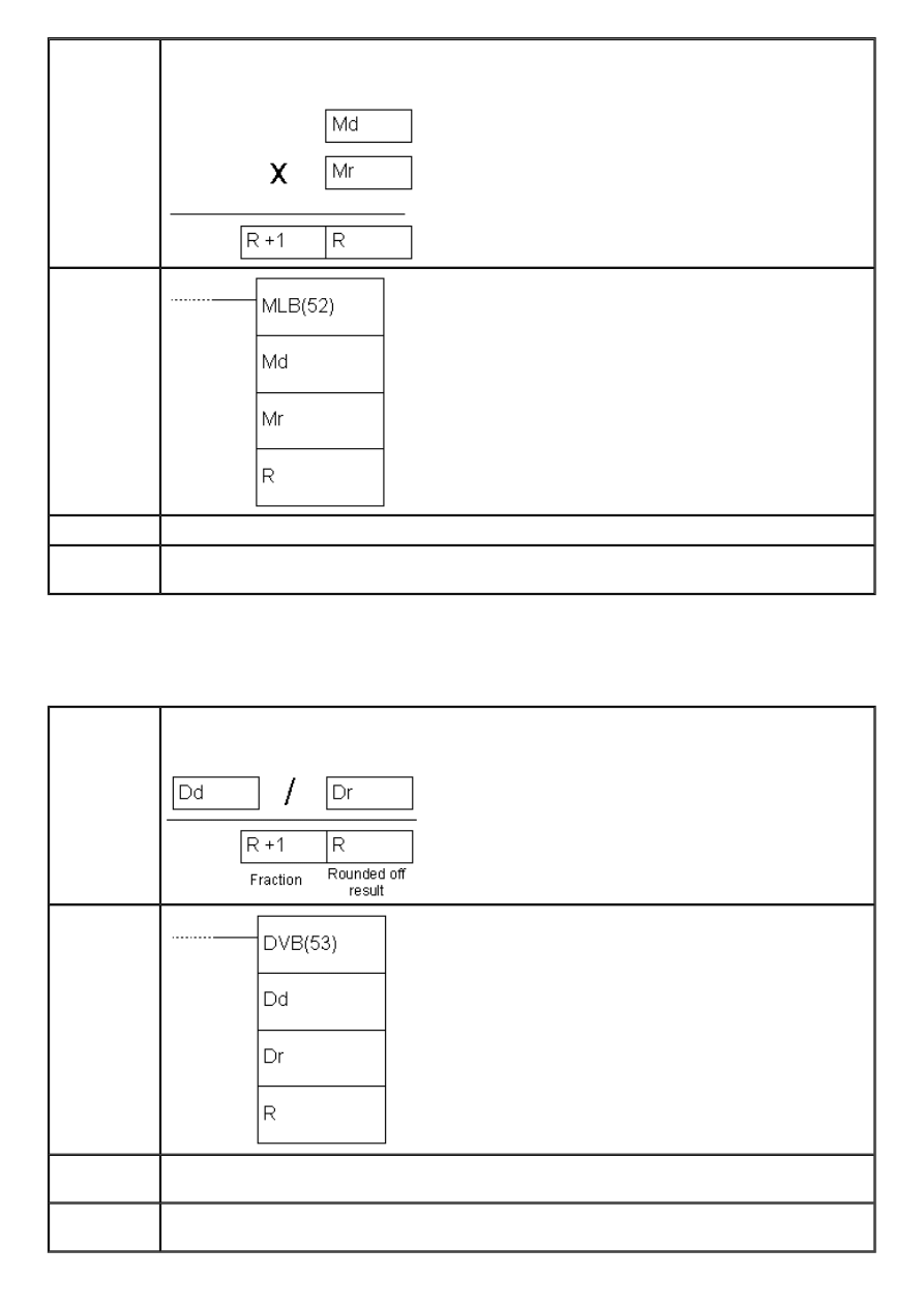
APPENDIX E - Ladder diagram instructions
Description
Instruction multiplies values of location Md by the value of location Mr. The result is
stored in two memory locations R and R+1.
Ladder
symbol
Limitations
Words DM6144 - DM6655 cannot be used as operand R.
Flag
ER flag changes state u ON in case of error.
EQ flag changes state u ON if the result equals “0”.
E.59 BINARY DIVIDE
- Binary division
Description
Instruction divides the value of location Dd with the value of location Dr. The result is
stored into location R, while the fraction is stored in R+1.
Ladder
symbol
Limitations
Words DM6144 - DM6655 cannot be used as operand R and the instruction cannot be
used for dividing signed numbers.
Flag
ER flag changes state to ON in case that Dr contains value “0”.
EQ flag changes state to ON if the result equals “0”.
http://www.mikroelektronika.co.yu/english/product/books/PLCbook/app_e/app_e2.htm (7 sur 35)05/11/2004 02:48:36
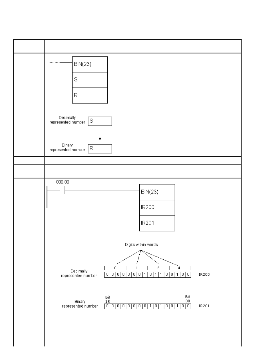
APPENDIX E - Ladder diagram instructions
E.60 BCD TO BINARY
- Converts decimal number to a binary number
Description
Instruction converts binary representation of decimal number from the word S to binary
number in the word R. Contents of the word S remains unchanged.
Ladder
symbol
Limitations
Words DM6144 - DM6655 cannot be used as operand R.
Flag
ER flag changes state to ON if the contents of the word S are not BCD.
EQ flag changes state to ON if the result equals “0”.
Example
Upon fulfilling the condition on bit IR000.00, instruction changes the contents of memory
location IR200 so that its numerical value remains unchanged; in other words, only the
representation of the location’s contents changes. If the contents of the location IR200 is
“164” decimal, this instruction would convert it to “0000000010100100”. One of the
purposes of this instruction is preparing the contents of memory location for one of the
binary operations.
http://www.mikroelektronika.co.yu/english/product/books/PLCbook/app_e/app_e2.htm (8 sur 35)05/11/2004 02:48:36
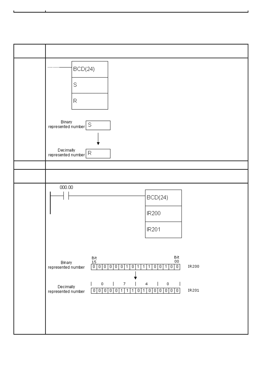
APPENDIX E - Ladder diagram instructions
E.61 BINARY TO BCD
- Converts binary number to a decimal number
Description
Instruction converts binary represented number from the word S to a decimal number in
the word R. Contents of the word S remains unchanged.
Ladder
symbol
Limitations
Word DM6144 - DM6655 cannot be used as operand R.
Flag
ER flag changes state to ON in case of error.
EQ flag changes state to ON if the result equals “0”.
Example
Upon fulfilling the condition on bit IR000.00, instruction changes the contents of memory
location IR200 so that its numerical value remains unchanged; in other words, only the
representation of the location’s contents changes. If the contents of location IR200 is
“000000101100100” binarny, this instruction would convert it to “740” decimaly. One of
the purposes of this instruction is preparing the contents of memory location for one of
BCD operations.
http://www.mikroelektronika.co.yu/english/product/books/PLCbook/app_e/app_e2.htm (9 sur 35)05/11/2004 02:48:36
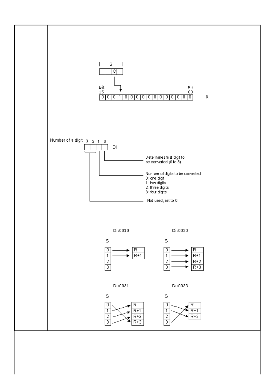
APPENDIX E - Ladder diagram instructions
E.62 4 TO 16 DECODER
- 4 to 16 decoder
Description
Instruction converts up to four 4-bit hexadecimal digits of values from 0 to 15. The result
of the instruction is stored into memory locations from address R to R+3, depending on
how many digits was converted. Converted digit in the result is represented with a set bit
on a position corresponding to the value of a digit. If the value of a digit is “C” (12
decimaly) the twelfth bit of the result word will be set.
The first digit to be converted, as well as the number of digits to be converted, is
determined in the control word Di. If the number of digits for conversion is greater than
the number of digits remaining in the word S, then the missing digits are taken from the
starting digit anew. The structure of the control word Di is shown on the picture below.
Some of the combinations of control word values along with their meaning are given
below:
http://www.mikroelektronika.co.yu/english/product/books/PLCbook/app_e/app_e2.htm (10 sur 35)05/11/2004 02:48:36
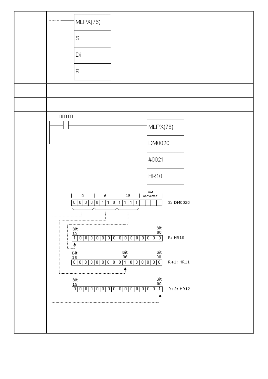
APPENDIX E - Ladder diagram instructions
Ladder
symbol
Limitations
Two rightmost digits of the word Di have to be between 0 and 3. Words DM6144 -
DM6655 cannot be used as operand R.
Flag
ER flag changes state to ON in case that (R + number of digits) exceeds the range of a
given memory block.
Example
Upon fulfilling the condition on bit IR000.00, instruction converts three digits from the
digit no.1 in the word DM0020. As there are three digits to be converted, the result will
take three memory locations starting from HR10. Digit 0 in the word DM0020 is not
converted.
E.63 16 TO 4 ENCODER
- 16 to 4 encoder
http://www.mikroelektronika.co.yu/english/product/books/PLCbook/app_e/app_e2.htm (11 sur 35)05/11/2004 02:48:36
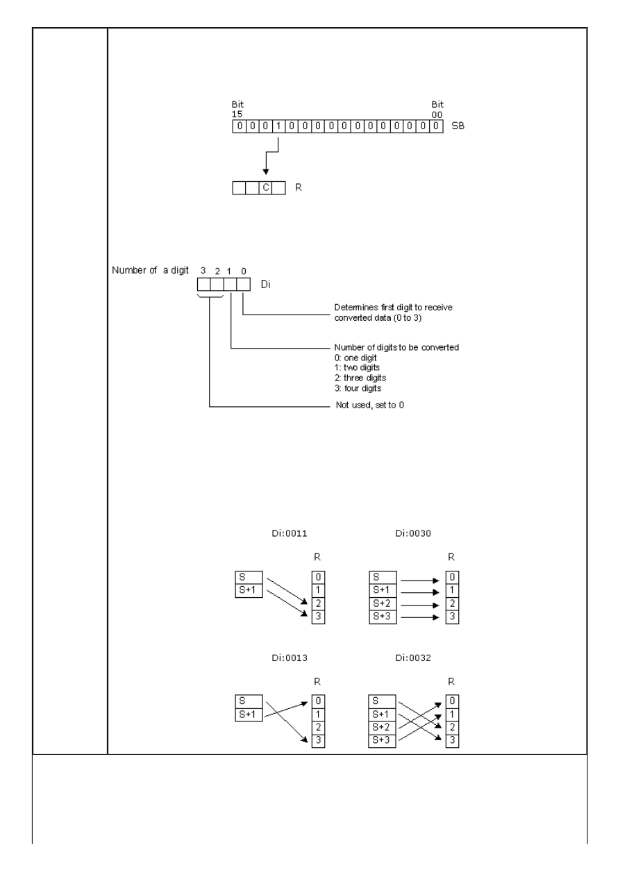
APPENDIX E - Ladder diagram instructions
Description
Instruction determines the highest set bit in SB and according to it, stores the 4-bit
hexadecimal value to a certain place in the result word R.
In the example below, bit 12 of the location on address SB is set, which would be “C” in a
hexadecimal representation.
Precise place for storing the converted value in the word R is determined by a control
word Di. The same word also determines the number of words to be converted, starting
from the address of the word SB. For this example, the control word would be “0001”.
The first digit to be converted, as well as the number of digits to be converted, is
determined in the control word Di. If the number of digits for conversion is greater than
the number of digits remaining in the word S, then the missing digits are taken from the
starting digit anew. The structure of the control word Di is shown on the picture above.
Some of the combinations of control word values along with their meaning are given
below:
http://www.mikroelektronika.co.yu/english/product/books/PLCbook/app_e/app_e2.htm (12 sur 35)05/11/2004 02:48:36
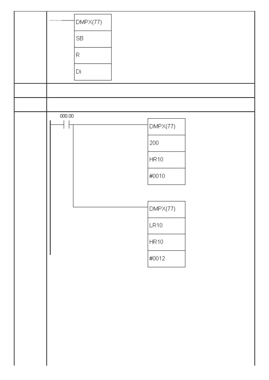
APPENDIX E - Ladder diagram instructions
Ladder
symbol
Limitations
Two rightmost digits of the word Di have to be between 0 and 3. Words DM6144 -
DM6655 cannot be used as operands R, SB and Di.
Flag
ER flag changes state to ON if (SB + number of digits) exceeds the range of a given
memory block or if the word to be converted equals zero.
Example
Upon fulfilling the condition on bit IR000.00, first DMPX instruction converts two words,
IR200 and IR201. The control word is “0010”, meaning that two words are converted
(digit 1) and stored starting from the zero digit in the result (rightmost digit 0). After the
first DMPX instruction, the second one is executed, converting two words from addresses
LR10 and LR11 and storing them in the result word HR10, starting from the digit no.2.
Therefore, the word HR10 contains four converted words in the following order: IR200,
IR201, LR10, LR11. More detailed explanation of how the instruction works is given on
the following picture.
http://www.mikroelektronika.co.yu/english/product/books/PLCbook/app_e/app_e2.htm (13 sur 35)05/11/2004 02:48:36
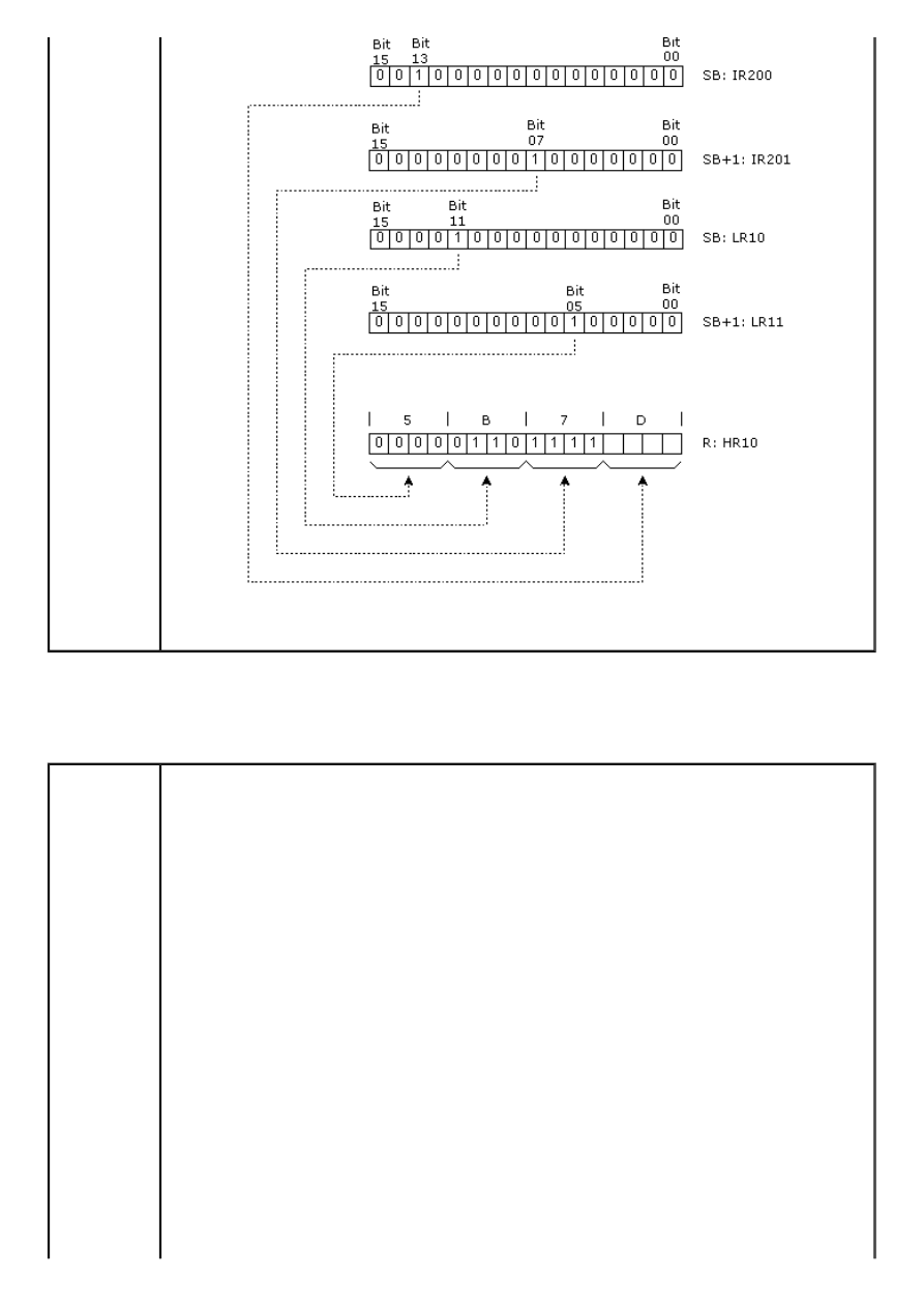
APPENDIX E - Ladder diagram instructions
Presuming that binary value is the one from locations IR200, IR201, LR10 and LR11, as in
example, the result of conversion in the result word HR10 would be “5B7D”.
E.64 ASCII CONVERT
- Converts to ASCII code
Description
Instruction converts digits from the word S to their ASCII equivalent and stores the result
in the words starting from the address D. The control word Di determines the first
converted digit, the number of digits to be converted and which half of the word D
contains the first 8-bit ASCII converted code. IIf the number of digits for conversion is
greater than the number of digits remaining in the word S, then the missing digits are
taken from the starting digit anew from the word S. Digit with the highest position of the
word Di has a role of parity bit and it can take values between 0 and 2 - not having
parity, parity and non-parity. Parity bit is actually a highest bit of the 8-bit ASCII code.
When the third digit of the word Di equals zero, this bit is always zero. If the third digit of
the word Di equals one, then this bit represents parity, or simply put, this bit is set when
the number of ones in the other 7 bits of ASCII is odd making the number of ones even.
If the ASCII value equals “31” (binary “0011 0001”), even parity would change the
highest bit to one, changing the ASCII number to “1011 0001” or “B1”. The status of
parity bit does not affect the interpretation of ASCII code. Odd parity bit behaves in
similar fashion, but with the opposite function. It’s purpose is to ensure that the number
of ones in ASCII code is always odd. The following picture represents interpreting the
value of word Di and the picture after that gives several versions of values of the word Di
and how they affect the instruction.
http://www.mikroelektronika.co.yu/english/product/books/PLCbook/app_e/app_e2.htm (14 sur 35)05/11/2004 02:48:36
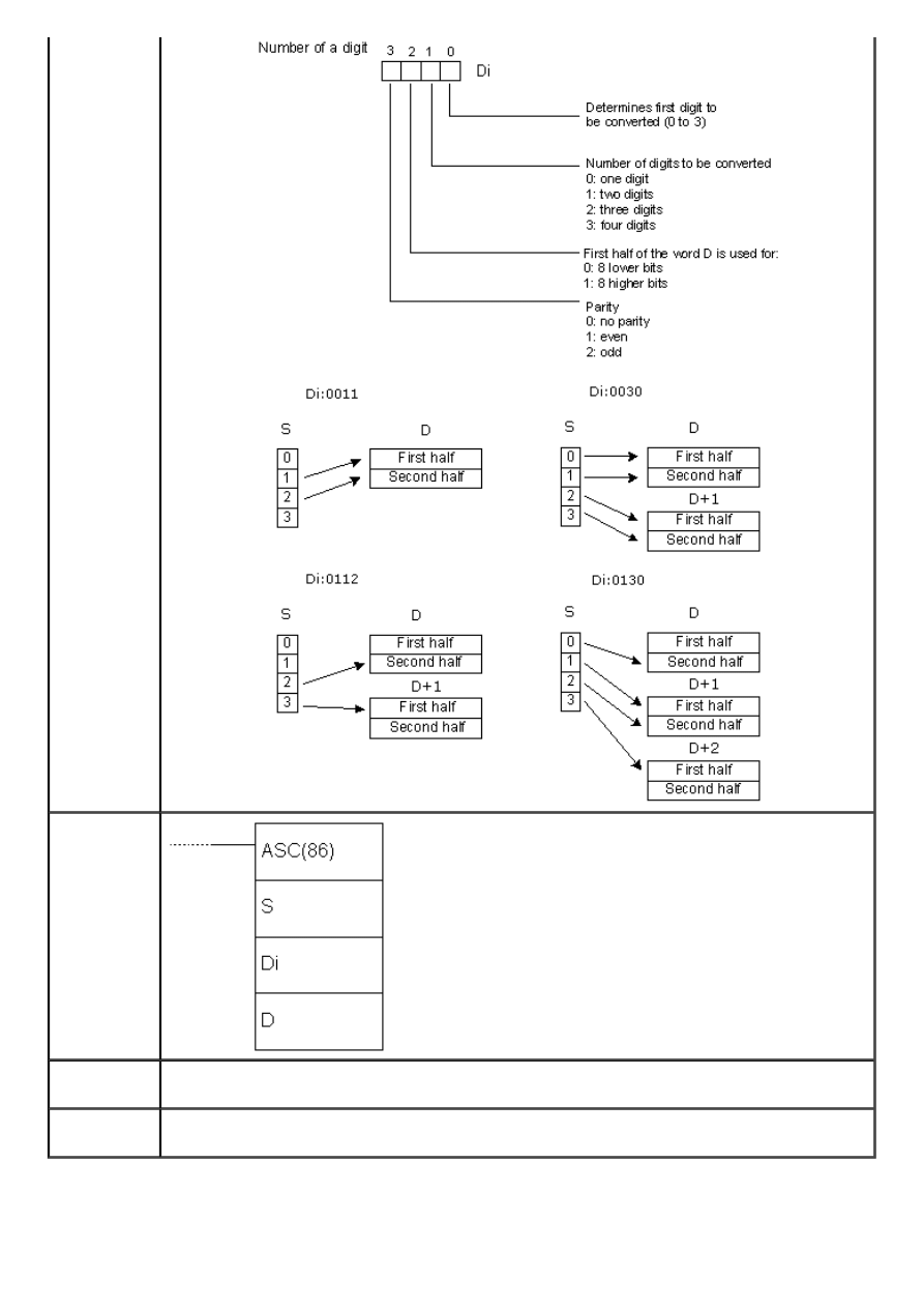
APPENDIX E - Ladder diagram instructions
Ladder
symbol
Limitations
Two lower digits of the words Di must have values betweenmoraju imati 0 and 3. Words
DM6144 - DM6655 cannot be used as operand D.
Flag
ER flag changes state to ON if two rightmost digits of the word Di do not fall within the
specified range (0-3) or the result word exceeds the boundaries of memory area.
E.65 COMPLEMENT
- Complements a word
http://www.mikroelektronika.co.yu/english/product/books/PLCbook/app_e/app_e2.htm (15 sur 35)05/11/2004 02:48:36
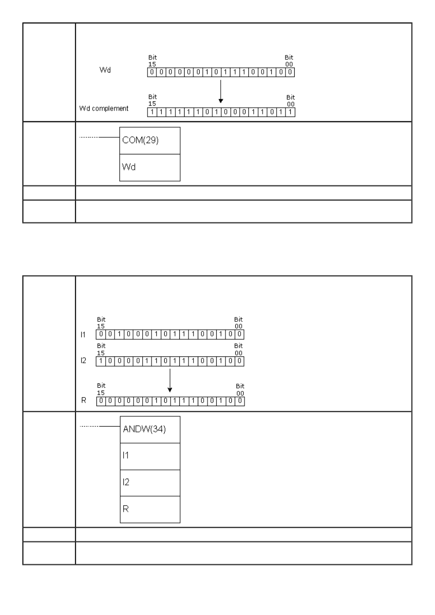
APPENDIX E - Ladder diagram instructions
Description
Instruction executes the second complement of the word Wd and stores it into word Wd
again. The second complement means that ones become zeros and vice versa.
Ladder
symbol
Limitations
Words DM6144 - DM6655 cannot be used as operand Wd.
Flag
ER flag changes state to ON in case of error.
EQ flag changes state to ON if the result equals zero.
E.66 LOGICAL AND
- Operation logical "AND" on the contents of a word
Description
Instruction executes the operation logical “AND” on words I1 and I2. The result of the
operation is stored into word R. Operation logical “AND” puts one in the result only if the
same position of words I1 and I2 also contain one.
Ladder
symbol
Limitations
Words DM 6144 - DM6655 cannot be used as operand R.
Flag
ER flag changes state to ON in case of error.
EQ flag changes state to ON if the result equals zero.
http://www.mikroelektronika.co.yu/english/product/books/PLCbook/app_e/app_e2.htm (16 sur 35)05/11/2004 02:48:36
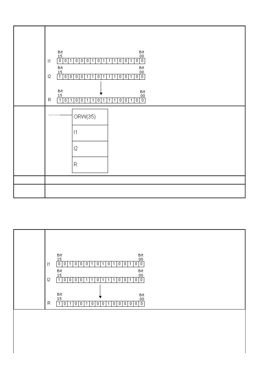
APPENDIX E - Ladder diagram instructions
E.67 LOGICAL OR
- Operation logical "OR" on the contents of a word
Description
Instruction executes the operation logical “OR” on words I1 and I2. The result of the
operation is stored into the word R. Operation logical “OR” puts the one in the result if at
least one of the words I1 and I2 contains one on that position.
Ladder
symbol
Limitations
Words DM6144 - DM6655 cannot be used as operand R.
Flag
ER flag changes state to ON in case of error.
EQ flag changes state to ON if the result equals zero.
E.68 EXCLUSIVE OR
- Operation "EXCLUSIVE OR" on the contents of a word
Description
Instruction executes operation “EXCLUSIVE OR” on the words I1 and I2. The result of the
operation is stored into the word R. Operation exlusive “OR” puts one in the result only if
the same position of the words I1 and I2 contains different values.
http://www.mikroelektronika.co.yu/english/product/books/PLCbook/app_e/app_e2.htm (17 sur 35)05/11/2004 02:48:36
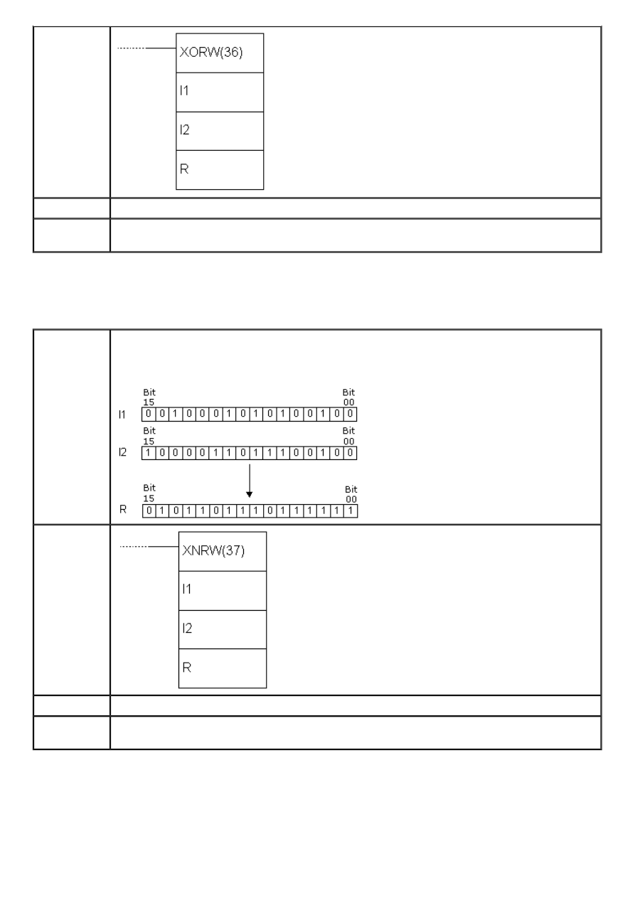
APPENDIX E - Ladder diagram instructions
Ladder
symbol
Limitations
Words DM6144 - DM6655 cannot be used as operand R.
Flag
ER flag changes state to ON in case of error.
EQ flag changes state to ON if the result equals zero.
E.69 EXCLUSIVE NOR
- Operation "EXCLUSIVE NOR" on the contents of a word
Description
Instruction executes operation “EXCLUSIVE OR” on the words I1 and I2. The result of the
operation is stored into the word R. Operation exclusive “NOR” puts one in the result only
if the same position of words I1 and I2 contains the same value, whether it is “0” or”1”.
Ladder
symbol
Limitations
Words DM6144 - DM6655 cannot be used as operand R.
Flag
ER flag changes state to ON in case of error.
EQ flag changes state to ON if the result equals zero.
E.70 BIT COUNTER
- Counts the number of ones in a given word
http://www.mikroelektronika.co.yu/english/product/books/PLCbook/app_e/app_e2.htm (18 sur 35)05/11/2004 02:48:36
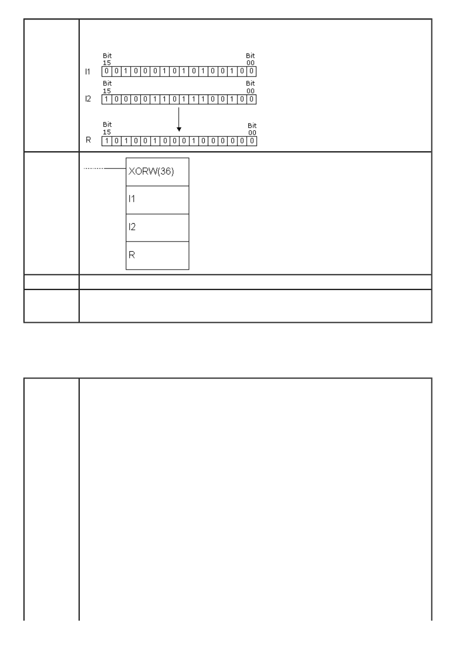
APPENDIX E - Ladder diagram instructions
Description
Instruction counts the number of bits with the state “1” in words from address SB to SB
+(N-1) and puts the result on the address of the word R.
Ladder
symbol
Limitations
Words DM6144 - DM6655 cannot be used as operand R. Word N cannot have zero value.
Flag
ER flag changes state to ON in case that N isn’t BCD number or in case that SB and SB
+(N-1) don’t belong to the same memory area.
EQ flag changes state to ON if the result equals zero.
E.71 SUBROUTINE ENTRY
- Enters the subroutine
Description
Instruction changes the course of the main program towards subroutine, at the
instruction line of the main program which contains the instruction SBS. Number of
instructions N has to be in 000 - 049 range. When the instruction condition is fulfilled, all
the instructions between SBN(92) and the first RET(92) instruction are executed. Upon
processing the RET instruction, program returns to the line immediately following the
instruction SBS which called the subroutine in the first place. The same subroutine may
be called from several places in the program.
http://www.mikroelektronika.co.yu/english/product/books/PLCbook/app_e/app_e2.htm (19 sur 35)05/11/2004 02:48:36
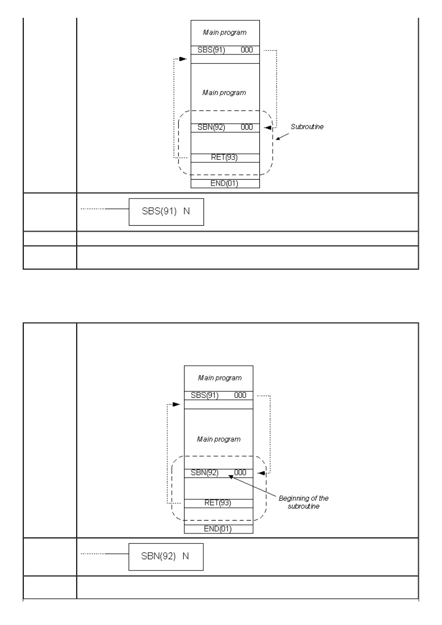
APPENDIX E - Ladder diagram instructions
Ladder
symbol
Limitations
Number of subroutine has to be in 000 - 049 range.
Flag
ER flag changes state to ON when non-existing subroutine is called, when the subroutine
calls itself or when the subroutine being executed at the moment is called.
E.72 SUBROUTINE DEFINE
- Beginning of a subroutine
Description
Instruction marks the beginning of a subroutine. Each subroutine is defined with its
number N. All subroutines have to be placed after the main program and instruction END
has to follow the last RET instruction of the last subroutine SBN.
Ladder
symbol
Limitations
Number of the subroutine has to be in 000 - 049 range. Each number may be used only
once.
http://www.mikroelektronika.co.yu/english/product/books/PLCbook/app_e/app_e2.htm (20 sur 35)05/11/2004 02:48:36
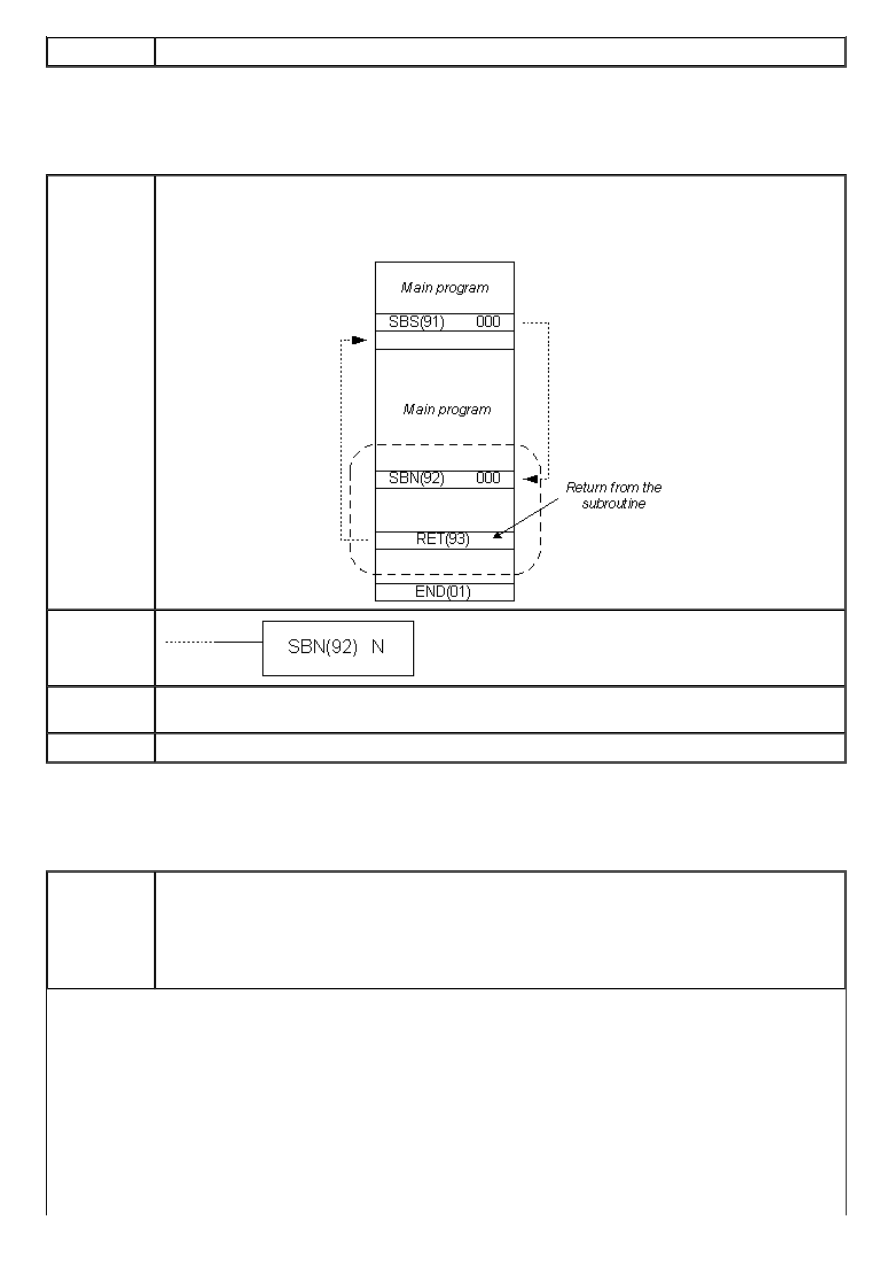
APPENDIX E - Ladder diagram instructions
Flag
It has no effect on any particular flag.
E.73 SUBROUTINE RETURN
- Return from a subroutine
Description
Instruction executes the return from the subroutine to the main program. Each
subroutine must contain the RET instruction. This instruction jas on number of its own,
naturally assuming that it belongs to the previous SBN instruction.
Ladder
symbol
Limitations
Number of the subroutine has to be in 000 - 049 range. Each number may be used only
once.
Flag
It has no effect on any particular flag.
E.74 MACRO
- Macro
Description
Instruction MCRO enables one subroutine to substitiute several subroutines having the
same structure, but different operands. Instruction has 4 input words SR232 to SR235
and 4 output words SR236 to SR239 used for sending or receiving the subroutine
parameters. Upon fulfilling the condition, the instruction copies the contents of locations
I1 - I3 to words SR232 - SR235. Upon execution of subroutine N, values of the words
SR236 - SR239 are copied to words O1 - O3.
http://www.mikroelektronika.co.yu/english/product/books/PLCbook/app_e/app_e2.htm (21 sur 35)05/11/2004 02:48:36
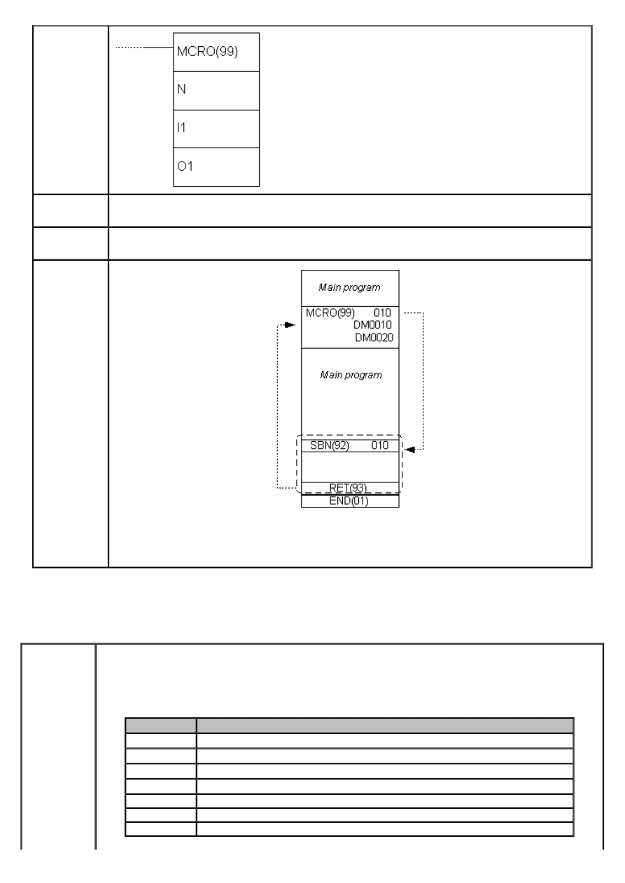
APPENDIX E - Ladder diagram instructions
Ladder
symbol
Limitations
Number of the subroutine has to be in 000 - 049 range. Each number may be used only
once.
Flag
ER flag changes state to ON when non-existing subroutine is called, when the subroutine
calls itself or when the subroutine, being executed at the moment, is called.
Example
Instruction MCRO calls the subroutine with the number 010. Contents of words DM0010 -
DM0013 is copied to SR232 - SR235 and upon execution of the instruction, contents of
words SR236 - SR239 is copied to the words DM0020 - DM0023.
E.75 INTERRUPT CONTROL
- Interrupt control
Description
Instruction controls the interrupts and executes one of the seven functions presented in the
table below, according to the value of the word C1.
C1
Function
000
Mask/unmask interrupts
001
Clear the interrupt input
002
Read the current mask for interrupt inputs
003
Reset decrement counter and unmask interrupts
004
Reset increment counter and unmask interrupts
100
Mask all interrupts
200
Unmask all interrupts
http://www.mikroelektronika.co.yu/english/product/books/PLCbook/app_e/app_e2.htm (22 sur 35)05/11/2004 02:48:36
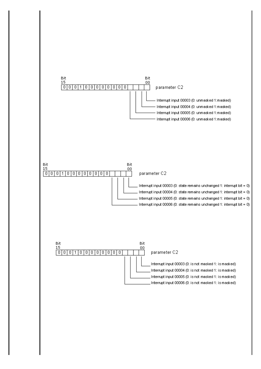
APPENDIX E - Ladder diagram instructions
NOTE: Value of the word C1 004 refers to models CPM2A/CPM2C of PLC controller, so it will not be detailed here.
C1=000
Function is used for masking and unmasking the interrupt inputs 00003 - 00006. Masked
interrupts are registered, but the part of the program assigned to them will not be executed
until the mask is off. Upon unmasking interrupt input, interrupt routine will immediately take
place (unless, in the meantime the bit corresponding to that interrupt input is reset with the
instruction INT, parameter C1=001). The input being masked or unmasked is determined by
parameter C2 according to the following scheme (bear in mind that we work with bits and not
with digits of the word C2). Bits 4, 5, 6...15 should be set to zero. All interrupt inputs are
masked upon starting the PLC controller.
C1=001
Function resets the registered interrupts, so that interrupt routine cannot take place upon
unmasking the interrupt input. Bits 4, 5, 6...15 of the word C2 should be set to zero.
C1=002
Function reads the status of the mask for interrupt inputs 00003 - 00006 and stores the read
state into the word C2. Interrupt input is masked if the state of the corresponding bit equals
“1”. Bits 00 - 03 correspond to interrupt inputs 00003 - 00006.
C1=003
Function restarts the interrupt inputs in the counter mode. The current counter value (SR240 -
SR243) is set to the starting state and the interrupt is unmasked. If C1=003, decremental
counter is restarted, while in the case of C1=004 incremental counter is restarted. As CPM1A
model of PLC does not feature incremental counter, this option should not be used. When
using the options C1=003 or C1=004 differencial form of the instruction shoud be used @INT
or else the current counter state (PV) will be reset to the starting state (SV) and the interrupt
will never be generated. Writing the value “0000” to the starting counter state and executing
the INT instruction with parameter C1=003 stops the counter and disables interrupts.
To start the counter again, non-zero value should be written to a starting value SV and the
instruction INT executed. Interrupts in the counter mode can be masked by executing the
http://www.mikroelektronika.co.yu/english/product/books/PLCbook/app_e/app_e2.htm (23 sur 35)05/11/2004 02:48:36
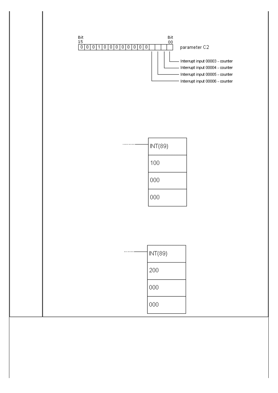
APPENDIX E - Ladder diagram instructions
instruction INT with parameter C1=000 and set corresponding bit in C2. If same is done, but
with “0” for the appropriate position in the word C2 interrupt input will behave as a regular
interrupt ulaz and not as counter interrupt input.
C1=100
Function masks all the interrupts including the interval timer interrupts and the high-speed
counter interrupts. Masked interrupts are registered, but are not executed. This function is
also called a global interrupt mask and it does not affect the masks of specific interrupts. This
option should be used for temporary disabling all the interrupts. It is cmmonly used in pair,
one function masks all the interrupts and the other one unmasks them. Function cannot be
used within the interrupt routine.
C1=200
Function unmasks all the interrupts including the interval timer interrupts and the high-speed
counter interrupts. If the specific interrupt is masked, global unmasking does not affect the
state of the specific interrupt input state. Function cannot be used within the interrupt routine.
http://www.mikroelektronika.co.yu/english/product/books/PLCbook/app_e/app_e2.htm (24 sur 35)05/11/2004 02:48:36
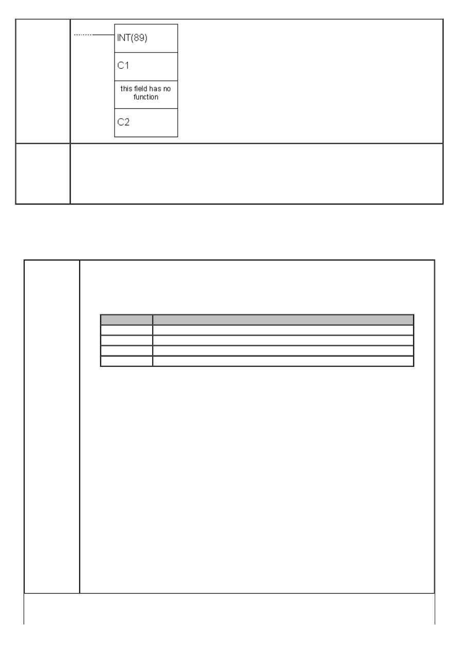
APPENDIX E - Ladder diagram instructions
Ladder
symbol
Flag
ER flag changes state to ON if:
C1 is not 000, 001, 002, 003, 004, 100 or 200.
C2 is not in 0000 - 000F range.
INT instruction is executed with C1=100 or 200 within the interrupt routine.
INT instruction is executed with C1=100 when all inputs are already masked.
INT instruction is executed with C1=200 when all inputs are already unmasked.
E.76 INTERVAL TIMER
- Interval timer
Description
Instruction is used for controling the timer interrupt. Instruction mode is determined
according to the value of the word C1.
C1
Function
000
Start the interrupt timer with only one timer
003
Start the timer with periodical interrupts
006
Read the current timer value
010
Stop the timer
C1=001 or 003
C2 can be either a constant or an address of a word in PLC controller memory.
C2=constant
If C2 is a constant, then it represents the starting value of decremental counter in BCD
format (form 0000 to 9999 which is equivalent to 0 - 9.999 ms) and C3 represents the
number of the interrupt routine (from 000 to 049).
C2=address of a word in memory
If C2 is a word in PLC controller memory, then its contents is a starting value of
decremental counter in BCD format. Cotents of the word C2+1 represents the
measurement unit (BCD, 0005 - 0320) in 0.1s decrements. Interval is, in that case, 0.5 -
32ms. Starting value of the timer is calculated as C2 * (C2+1) * 0.1s. C3 represents the
number of the interrupt routine.
C1=006
Function reads the current timer state. Parameter C2 represents the memory address
where the read timer state is stored, while C2+1 stores the measurement unit. Parameter
C3 reresents the memory address where the data concerning the time passed since the
last decrementation of timer in BCD format is stored in 0.1s units.
C1=010
Function stops the timer. Parameters C2 and C3 are without function and should be set to
“0000”.
http://www.mikroelektronika.co.yu/english/product/books/PLCbook/app_e/app_e2.htm (25 sur 35)05/11/2004 02:48:36
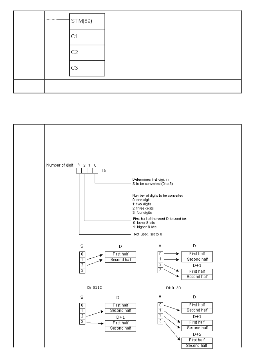
APPENDIX E - Ladder diagram instructions
Ladder
symbol
Flag
ER flag changes state to ON if C1 is not 000, 003, 006 or 010 or in case that the number
of interrupt routine is not within 0000 - 0049 range.
E.77 7-SEGMENT DECODER
- Seven-segment decoder
Description
Instruction translates the digits of the word S to 8-bit 7-segment code and stores it into
destination word D. The control word Di determines the first digit of S to be translated,
number of digits to be translated and which half of the word D will contain the result of
the first translation. The following picture interprets the values of digits of the word Di
and the picture after that displays a few versions of the word Di and how they affect the
instruction.
http://www.mikroelektronika.co.yu/english/product/books/PLCbook/app_e/app_e2.htm (26 sur 35)05/11/2004 02:48:36
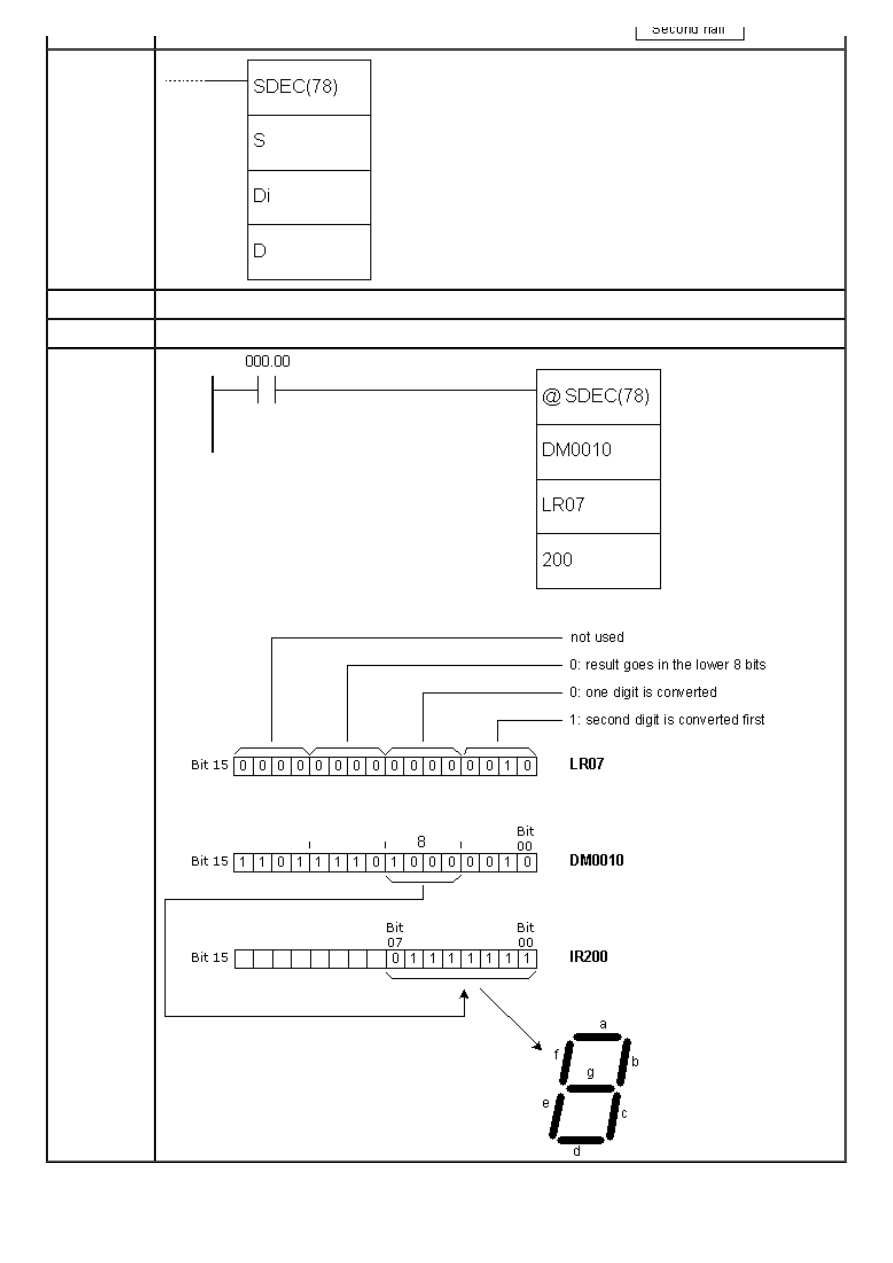
APPENDIX E - Ladder diagram instructions
Ladder
symbol
Limitations
Words DM6144 - DM6655 cannot be used as operand D.
Flag
ER flag changes state to ON in case of error.
Example
http://www.mikroelektronika.co.yu/english/product/books/PLCbook/app_e/app_e2.htm (27 sur 35)05/11/2004 02:48:36
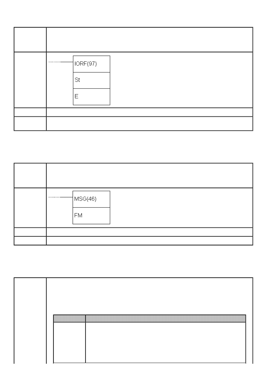
APPENDIX E - Ladder diagram instructions
E.78 I/O REFRESH
- Premature writing to I/O table
Description
Instruction checks the states of words from the address St to the address E and refreshes
them according to the current state of the program. Instruction is used when we want to
know the state of certain bit without waiting it to be refreshed in the course of regular
cycle of refreshing the inputs and outputs of PLC controller (IR000 - IR019).
Ladder
symbol
Limitations
Address of the word St has to be lower or equal to the address of the word E.
Flag
ER flag changes state to ON if words St and E do not belong to IR000 - IR019 range or in
case that the address of the word St is greater than the address of the word E.
E.79 MESSAGE
- Displays message in the programming console
Description
Instruction reads the contents of eight words from the address FM and displays them in
the program console. Contents of the word has to be in ASCII format, with every word
containing 2 ASCII characters. If not all the words are to be displayed in the console,
displaying can be stopped if the string “OD” is put into following word.
Ladder
symbol
Limitations
Words DM6144 - DM6655 cannot be used as operand FM.
Flag
ER flag changes state to ON in case of error.
E.80 MODE CONTROL
- Controls the high-speed counter or the pulse output
Description
Instruction controls the high-speed counter. There are several functions depending on
parameters P, C and P1. Parameter P defines if either high-speed counter or pulse output
will be controlled with this instruction.
P
Function
000
Designates the input of PLC controller that will be used as high-speed
counter (000.00, 000.01 and 000.02). Determines mono-phase signal
of logical zero with no acceleration/deceleration (outputs 010.00 and
010.01)
Determines mono-phase signal of logical zero with trapezoid
acceleration/deceleration (output 010.00)
http://www.mikroelektronika.co.yu/english/product/books/PLCbook/app_e/app_e2.htm (28 sur 35)05/11/2004 02:48:36
APPENDIX E - Ladder diagram instructions
010
*
Determines mono-phase signal "1" with no acceleration/deceleration
(output 010.01)
100
*
Designates interrupt input 0 in counter mode (input 000.03)
101
*
Designates interrupt input 1 in counter mode (input 000.04)
102
*
Designates interrupt input 2 in counter mode (input 000.05)
103
*
Designates interrupt input 3 in counter mode (input 000.06)
NOTE: * refers to CPM2A/CPM2C PLC controller models.
C
P1
Function
000
000
Starts comparing the current value with the
values from comparison table (CTBL)
001
000
Stops comparing the current value with the
values from comparison table (CTBL)
002
New value of the
current state (PV)
Changes the current value PV of high-speed
counter or interrupt input in counter mode
003
000
Stops the pulse output
005
*
New value of the
current state (PV)
Changes the current state of pulse output
006
*
000
Stops the synchronized pulse output
NOTE: * refers to CPM2A/CPM2C PLC controller models.
C=000 or C=001
Function starts or stops comparing the current value of high-speed counter PV with the
values from the comparison table created with instruction CTBL. If the comparison table
wasn’t created ahead of executing the INI instruction, the error occurs. Generally, when
INI instruction with C=000 is used, differential form @INI is recommended, because one
set of starting comparisons is sufficient.
C=002
Function changes value of the current state of the high-speed counter or the interrupt in
the counter mode.
Fast counter PV ( P=0 )
Function changes the contents of PV to 8-digit BCD number contained in the words P1
and P1+1. If differential-phase mode or ”up/down “ input mode is used, PV can have
value between F838 8608 and 0838 8607, where “F” as the first digit is treated as a
minus sign. PV can have value between 000 0000 and 1677 7215 in incremental mode.
Interrupt counter input PV ( P=100, P=101, P=102, P=103)
Function changes the contents of PV to 4-digit hexadecimal number from the word P1
(from 0000 to FFFF).
C=003
Function stops the pulse output.
C=004
Function changes the value of the current PV pulse output state to an 8-digit BCD value in
the words P1 and P1+1. Change cannot be done while the pulse output is in function.
New value can be from -16.777.215 to +16.777.215. Bit no.15 of the word P1+1 behaves
like a sign: “0” stands for positive, “1” stands for negative number.
C=003
Function stops the synchronized pulse output.
http://www.mikroelektronika.co.yu/english/product/books/PLCbook/app_e/app_e2.htm (29 sur 35)05/11/2004 02:48:36
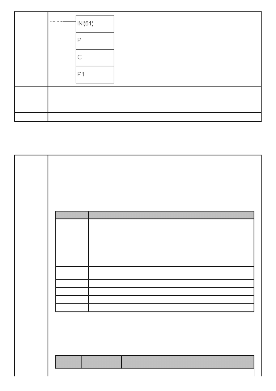
APPENDIX E - Ladder diagram instructions
Ladder
symbol
Limitations
If CPM1 or CPM1A PLC controller is used, parameter P has to be 000 and parameter C has
to be 000, 001, 002 or 003. P1 has to be 000 if C is not 002 or 004. If an address from
DM memory area is used as parameter P1, reading and writing to that location has to be
enabled.
Flag
ER flag changes state to ON if comparison table exceeds one memory area.
E.81 HIGH-SPEED COUNTER PV READ
- Reads the current value of high-speed counter
Description
Instruction controls the current state of high-speed counter, pulse output, interrupt input
in counter mode or input frequency for synchronized input. There are several functions
depending on parameters P, C and D.
Parameter P defines if either high-speed counter or pulse output will be controlled with
this instruction.
P
Function
000
Designates the input of PLC controller that will be used as high-speed
counter (inputs 000.00, 000.01 and 000.02). Designates input
frequency for synchronized pulse input (inputs 000.00, 000.01 and
000.02). Determines mono-phase signal of logical zero with no
acceleration/deceleration (outputs 010.00 and 010.01)
Determines mono-phase signal of logical zero with trapezoid
acceleration/deceleration (output 010.00)
010
*
Determines mono-phase signal "1" with no acceleration/deceleration
(output 010.01)
100
*
Designates interrupt input 0 in counter mode (input 000.03)
101
*
Designates interrupt input 1 in counter mode (input 000.04)
102
*
Designates interrupt input 2 in counter mode (input 000.05)
103
*
Designates interrupt input 3 in counter mode (input 000.06)
NOTE: * refers to CPM2A/CPM2C PLC controller models.
Control word determines the type of data to be accessed.
C
Destination
word
Function
http://www.mikroelektronika.co.yu/english/product/books/PLCbook/app_e/app_e2.htm (30 sur 35)05/11/2004 02:48:36
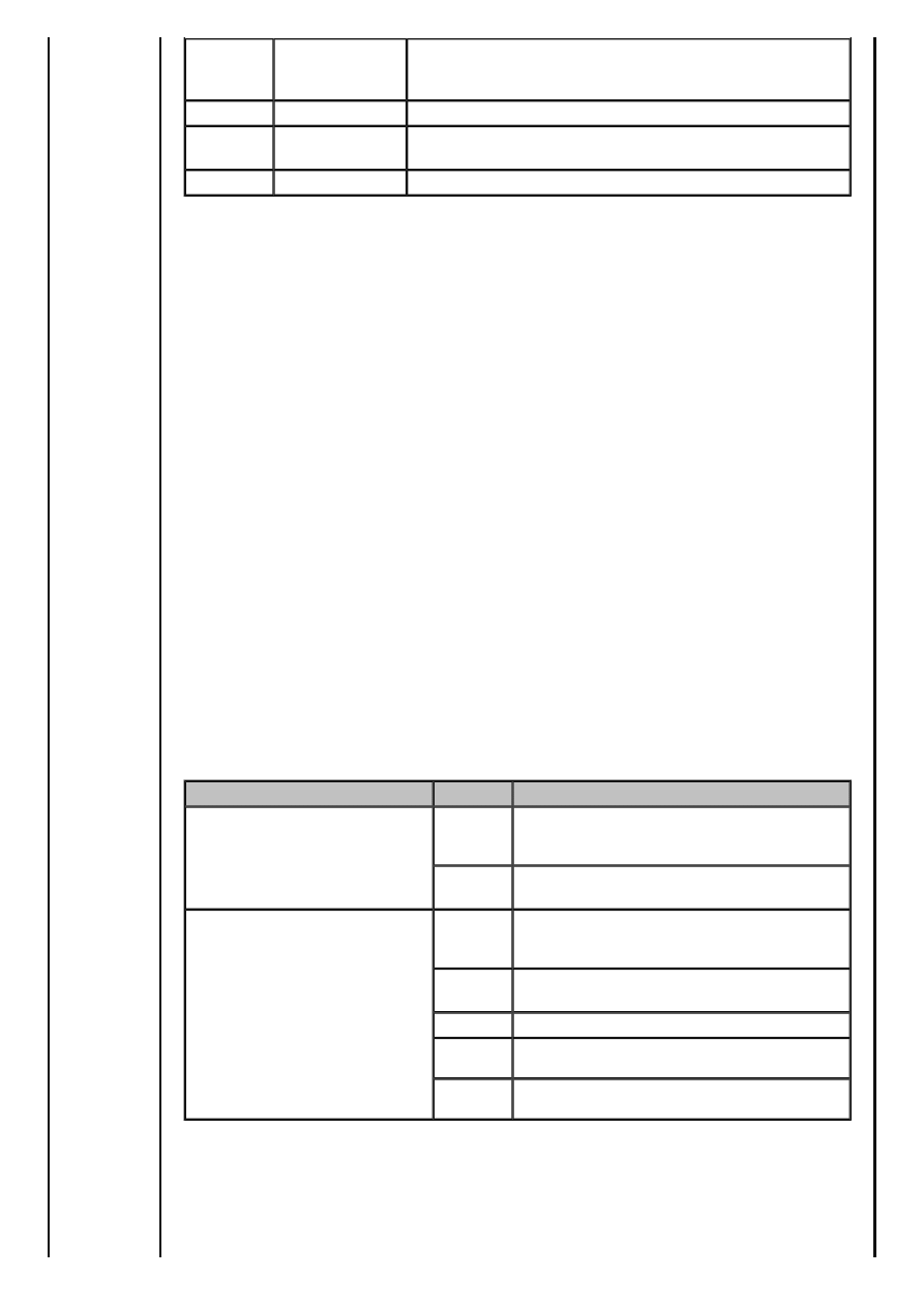
APPENDIX E - Ladder diagram instructions
000
D and D+1
Reads the current state of high-speed counter, of
interrupt input in counter mode or input frequency of
synchronized pulse control
001
D
Reads the status of high-speed counter or pulse output
002
D
Reads the results of comparing with values from
comparison table
003
D and D+1
Reads the current value of pulse output
NOTE: * refers to CPM2A/CPM2C PLC controller models.
C=000
Function reads the current value of PV of the specified high-speed counter or the interrupt
input in counter mode.
Fast counter PV or input frequency (P=000)
When the output is used as the high-speed counter, instruction reads the current value of
the specified fast counter and writes an 8-digit BCD value to D and D+1.
If differential-phase mode or ”up/down “ input mode is used, PV can have value between
F838 8608 and 0838 8607, where “F” as the first digit is treated as a minus sign. PV can
have value between 000 0000 and 1677 7215 in incremental mode. When the input is
used as synchronic pulse input, the instruction reads the input frequency and writes an 8-
digit BCD value to D and D+1. Range of the input frequency is 0000 0000 - 0002 0000.
Interrupt counter input PV ( P=100, P=101, P=102, P=103)
Function changes the contents of PV to 4-digit hexadecimal number from the word D
(from 0000 to FFFF).
C=001
Function reads the status of the high-speed counter or the pulse input and stores the
data into D.
Status of the high-speed counter or the pulse input 0 (P=000)
The table below shows the function of bits in the word D when P=000. Bits not mentioned
are not used and are always zero.
For...
Bit
Function
High-speed counter
00
Status of comparing high-speed counter
with values from comparison table
(0: not
compared, 1:compared)
01
High-speed counter below/above the
specified value
(0: in range, 1:out of range)
Pulse output
05
Total number of pulses defined for pulse
output 0
(0: number of pulses not defined, 1:
number of pulses defined)
06
Defined number of pulses on output 0
executed
(0: not executed, 1:executed)
07
Pulse output 0 state
(0: stopped, 1:executing)
08
Current state PV of pulse output
(0: in
range, 1:out of range)
09
Rate on pulse output 0
(0: constant, 1:
accelerates/decelerates)
Status of the pulse output 1 (P=010)
The table below shows the function of bits in the word D when P=010. Bits not mentioned
are not used and are always zero.
http://www.mikroelektronika.co.yu/english/product/books/PLCbook/app_e/app_e2.htm (31 sur 35)05/11/2004 02:48:36
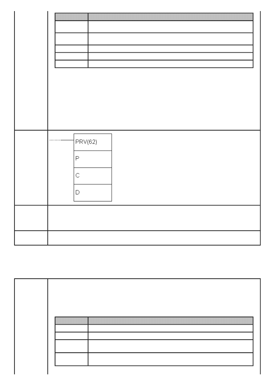
APPENDIX E - Ladder diagram instructions
Bit
Function
05
Total number of pulses defined for pulse output 1
(0: number of pulses
not defined, 1:number of pulses defined)
06
Defined number of pulses on output 1 executed (
0: not executed, 1:
executed)
07
Pulse output 1 state
(0: stopped, 1:executing)
08
Current state PV of pulse output
(0: in range, 1:out of range)
09
Rate on pulse output 1
(0: constant, 1:accelerates/decelerates)
C=002
Function reads the result of comparing the current value PV with 8 areas defined by
instruction CTBL and stores data into D. Bits 0 to 7 contain the results of comparing with
8 ranges from the comparison table (0: not in range, 1: in range).
C=003
Function reads the value of current state of PV pulse output and stores it to 8-digit BCD
value in words D and D+1. PV can have value from -16.777.215 to +16.777.215. Bit
no.15 of the word D+1 behaves like a sign: “0” stands for positive, “1” stands for
negative number.
Ladder
symbol
Limitations
If CPM1 or CPM1A PLC controller is used, parameter D has to be 000 and parameter C
has to be 000, 001 or 002. If an address from DM memory area is used as parameter D,
reading and writing to that location has to be enabled.
D and D+1 have to belong to the same memory area.
Flag
ER flag changes state to ON if an error concerning the value of instruction operand
occurred.
E.82 COMPARISON TABLE LOAD
- Defines a comparison table
Description
Instruction forms the comparison table for working with high-speed counter. Depending
on parameter C, comparison can be immediate or it can be called upon with instruction
INI.
C
Function
000
Registers comparison table containing values and starts comparing
001
Registers comparison table containing ranges and starts comparing
002
Registers comparison table containing values. Comparing starts with
INI instruction
003
Registers comparison table containing ranges. Comparing starts with
INI instruction
http://www.mikroelektronika.co.yu/english/product/books/PLCbook/app_e/app_e2.htm (32 sur 35)05/11/2004 02:48:36
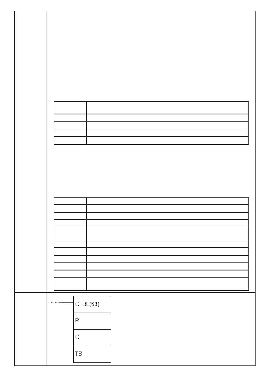
APPENDIX E - Ladder diagram instructions
When the current value of PV matches some of the specified table values or it belongs to
one of the specified ranges, the appropriate subroutine is called. If the high-speed
counter is not enabled in PC area (DM6642) instruction CTBL cannot be executed.
Comparing with values
Comparison table can have up to 16 values. Each of these values is assigned a number of
subroutine that is called when the current value matches the table value. With CPM1 and
CPM1A models, comparison is done one at a time in each cycle, while with models CPM2A
and CPM2C comparison is done for all table values simultaneously. After comparing with
the last table value, comparison starts from the first value again. The table below shows
the structure of the comparison table containing values.
Each value is assigned three words in the table. If the value “FFFF” is used as the number
of subroutine, no subroutine will be executed in case of a match.
TB
Number of values that current value is compared with (0001 to 0016,
BCD)
TB+1
Value no.1 (lower four digits in BCD format)
TB+2
Value no.1 (higher four digits in BCD format)
TB+3
Number of subroutine for matching the first value
...
Comparing with a range of values
Comparison table with ranges contains 8 ranges, which the current value PV is compared
with. Ranges can overlap, allowing that the current value PV falls into several of these; in
this case, the subroutine of the first matching area is called. If the value “FFFF” is used as
the number of subroutine, no subroutine will be executed in case of a match.
TB
Lower value no.1 (lower four digits in BCD format)
TB+1
Lower value no.1 (higher four digits in BCD format)
TB+2
Higher value no.1 (lower four digits in BCD format)
TB+3
Higher value no.1 (higher four digits in BCD format)
TB+4
Number of subroutine in case that the current value PV is within
range no.1
...
TB+35
Lower value no.8 (lower four digits in BCD format)
TB+36
Lower value no.8 (higher four digits in BCD format)
TB+37
Higher value no.8 (lower four digits in BCD format)
TB+38
Higher value no.8 (higher four digits in BCD format)
TB+39
Number of subroutine in case that the current value PV is within
range no.8
Ladder
symbol
http://www.mikroelektronika.co.yu/english/product/books/PLCbook/app_e/app_e2.htm (33 sur 35)05/11/2004 02:48:36
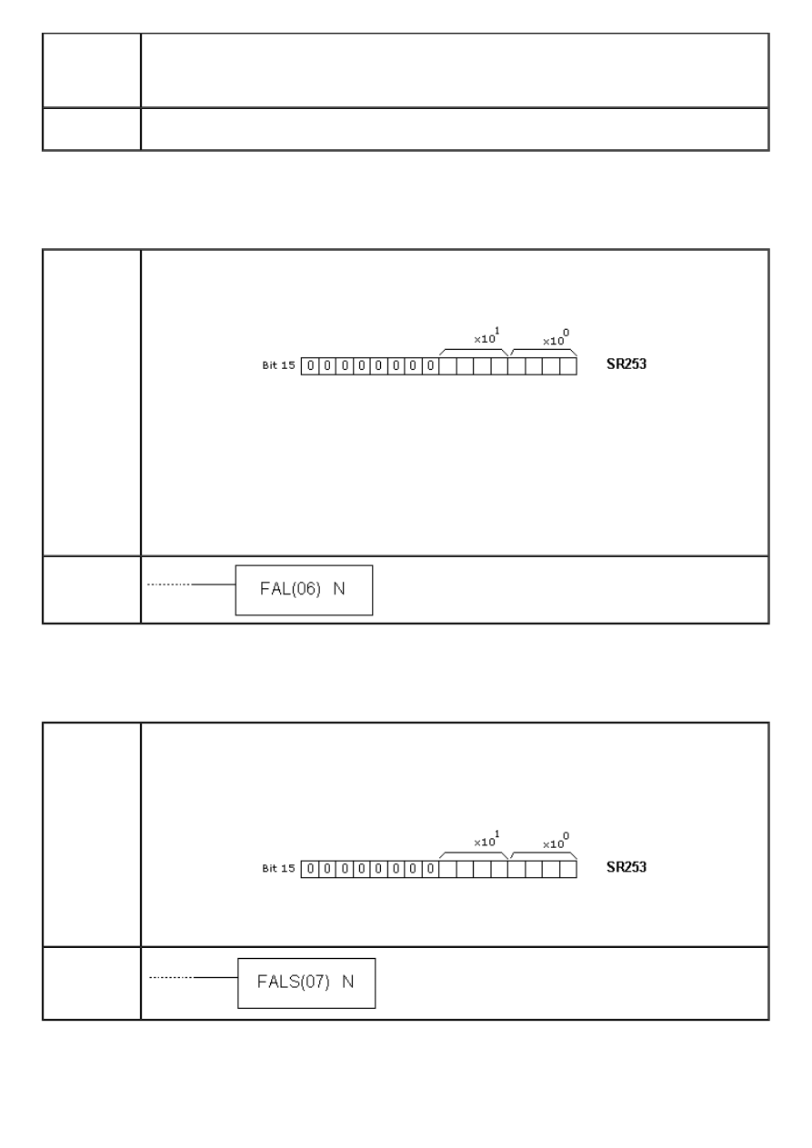
APPENDIX E - Ladder diagram instructions
Limitations
In each area lower border has to be lower than the upper border. Number of subroutine
can be used for several ranges.
Table has to belong to a single memory area. Parameter D has to be 000 and the
parameter C has to be 000, 001, 002 or 003.
Flag
ER flag changes state to ON if an error concerning the value of instruction operand
occurred.
E.83 FAILURE ALARM AND RESET
- Generates error code
Description
Instruction generates the code of an error that took place, so that the programmer can
use that information for debugging or program maintenance. Error code is stored in the
first 8 bits of the word SR253 and has value between 01 and 99.
In case of multiple errors, only one code will be displayed. To display the other codes, it
is necessary to reset bits 00-07 of the word SR253 via instruction FAL with parameter
N=00. Upon each reset, new error code will be displayed (if there is more than one
error). Error code remains in PLC controller memory after the power is off. When error
occurs, besides the code, programmer will be notified with blinking diode on the casing of
PLC controller.
Instruction FAL with parameter N=0 may be used for resetting the message created with
the instruction MSG.
Ladder
symbol
E.84 SEVERE FAILURE ALARM
- Generates fatal error code
Description
Instruction generates the code of an error that took place, so that the programmer can
use that information for debugging or program maintenance. Error code is stored in the
first 8 bits of the word SR253 and has value between 01 and 99. Upon occurence of fatal
error, diode ALARM/ERROR turns on on the casing of PLC controller and the PLC stops
operating.
PLC controller continues the program execution only when cause of error is removed.
Error code remains written and may be read.
Ladder
symbol
E.85 SET CARRY
- Sets carry bit
http://www.mikroelektronika.co.yu/english/product/books/PLCbook/app_e/app_e2.htm (34 sur 35)05/11/2004 02:48:36
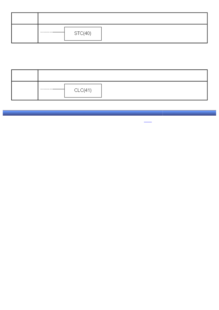
APPENDIX E - Ladder diagram instructions
Description
Instruction changes the state of carry bit CY to ON. Carry bit is an integral part of the
word SR255, and its address is SR255.04.
Ladder
symbol
E.86 CLEAR CARRY
- Resets carry bit
Description
Instruction changes state of carry bit CY to OFF. Carry bit is an integral part of the word
SR255, and its address is SR255.04.
Ladder
symbol
© C o p y r i g h t 2 0 0 3. m i k r o E l e k t r o n i k a. All Rights Reserved. For any comments contact
.
http://www.mikroelektronika.co.yu/english/product/books/PLCbook/app_e/app_e2.htm (35 sur 35)05/11/2004 02:48:36
Document Outline
- www.mikroelektronika.co.yu
- Acr15B.tmp
- www.mikroelektronika.co.yu
- Acr15F.tmp
- www.mikroelektronika.co.yu
- Acr163.tmp
- www.mikroelektronika.co.yu
- Acr167.tmp
- www.mikroelektronika.co.yu
- Acr16B.tmp
- www.mikroelektronika.co.yu
- Acr16F.tmp
- www.mikroelektronika.co.yu
- Acr173.tmp
- www.mikroelektronika.co.yu
- Acr177.tmp
- www.mikroelektronika.co.yu
- Acr17B.tmp
- www.mikroelektronika.co.yu
- Acr17F.tmp
- www.mikroelektronika.co.yu
- Acr183.tmp
- www.mikroelektronika.co.yu
- Acr187.tmp
- www.mikroelektronika.co.yu
- Acr18B.tmp
- www.mikroelektronika.co.yu
- Acr18F.tmp
- www.mikroelektronika.co.yu
- Acr193.tmp
- www.mikroelektronika.co.yu
Wyszukiwarka
Podobne podstrony:
IntroductoryWords 2 Objects English
lecture3 complexity introduction
Introduction to VHDL
ZMPST 01 Introduction
Lecture1 Introduction Femininity Monstrosity Supernatural
Introduction Gencontroller C620 Nieznany
268257 Introduction to Computer Systems Worksheet 1 Answer sheet Unit 2
Lab 03 C introduction
Introduction To Scholastic Ontology
asp net introduction MM6QQFHOGEVK7FULUA
kok introduction pl
Evans L C Introduction To Stochastic Differential Equations
Zizek, Slavoj Looking Awry An Introduction to Jacques Lacan through Popular Culture
Chapter 1 Introduction
Introduction to Lagrangian and Hamiltonian Mechanics BRIZARD, A J
First Year Polish Course introduction
launch cresetter oil lamp reset tool introduction
więcej podobnych podstron