SERVICE MANUAL
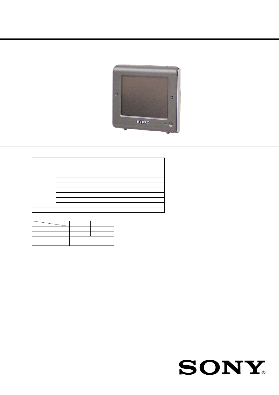
PERSONAL NAVIGATION SYSTEM
Photo: NV-U71T
9-887-431-01
2006K05-1
© 2006.11
Sony Corporation
eVehicle Division
Published by Sony Techno Create Corporation
– Continued on next page –
NV-U51/U71T
NV-U51A/U51B/U51D/U51F/U51G/U51I/U51N/U51S
SPECIFICATIONS
US Model
Canadian Model
NV-U71T
AEP Model
NV-U51A/U51B/U51D/U51F/
U51I/U51N/U51S/U71T
UK Model
NV-U51G/U71T
Model Name
Product Name
Distination
(Printed on Model Number Label)
NV-U51A
Central European
NV-U51B
Benelux
NV-U51D
German, Austrian, Swiss
NV-U51
NV-U51F
French
NV-U51G
UK
NV-U51I
Italian, Greek
NV-U51N
Nordic
NV-U51S
Iberia
NV-U71T
NV-U71T
US, Canadian, AEP, UK
NV-U51
NV-U71T
Main unit
*
NV-U71T
Cradle
NVA-CU4
NVA-CU4T
Car battery adapter
XA-DC2
AC power adapter
XA-AC13
COMPONENT MODEL NAME
*
Note:
Refer to the above table for the model name being written in
MODEL NUMBER LABEL of the main unit.
Main unit
Operating temperature: 5 – 45 ºC (41 – 113 ºF)
Power requirements: DC 5 V
(from supplied AC power adapter)
Connection terminals:
Cradle connector
DC IN 5V jack
USB jack
External GPS antenna (aerial) jack
Speaker: 20
× 40 mm (0.8 × 1.6 in) oval speaker
Consumption current: Approx. 0.5 A
Dimensions: Approx. 103.8
× 87.6 × 32.8 mm
(4.1
× 3.5 × 1.3 in)
(w
× h × d, protruding parts excluded)
Mass: Approx. 280 g (9.9 oz)
Monitor
System: Transmissive liquid crystal display
Drive system: a-Si TFT active matrix system
Dimensions: 3.5 in (4:3)
Approx. 70.1
× 52.6, 87.6 mm
(2.8
× 2.1, 3.5 in) (h × v, d)
Segment: 230,400 (960
× 240) dots
Cradle
Operating temperature: 5 – 45 ºC (41 – 113 ºF)
Power requirements: DC 5.2 V
(from supplied 12 V car battery adapter (negative
earth))
Connection terminals:
Unit connector
DC IN 5.2V jack
TMC aerial jack (NV-U71T only)
Reception frequency: 87.5 – 108.0 MHz
(NV-U71T only)
DISTINATION TABLE

2
NV-U51/71T
SAFETY-RELATED COMPONENT WARNING!!
COMPONENTS IDENTIFIED BY MARK
0
OR DOTTED LINE
WITH MARK
0
ON THE SCHEMATIC DIAGRAMS AND IN
THE PARTS LIST ARE CRITICAL TO SAFE OPERATION.
REPLACE THESE COMPONENTS WITH SONY PARTS WHOSE
PART NUMBERS APPEAR AS SHOWN IN THIS MANUAL OR
IN SUPPLEMENTS PUBLISHED BY SONY.
Built-in battery charging time/usage
time
Charging time
With the supplied car battery adapter/AC power
adapter: Approx. 4.5 hours (with unit turned on),
or 2.5 hours (in standby mode)
Usage time
Up to 6.5 hours (depending on usage)
ATTENTION AU COMPOSANT AYANT RAPPORT
À LA SÉCURITÉ!
LES COMPOSANTS IDENTIFIÉS PAR UNE MARQUE
0
SUR
LES DIAGRAMMES SCHÉMATIQUES ET LA LISTE DES
PIÈCES SONT CRITIQUES POUR LA SÉCURITÉ DE
FONCTIONNEMENT. NE REMPLACER CES COM- POSANTS
QUE PAR DES PIÈCES SONY DONT LES NUMÉROS SONT
DONNÉS DANS CE MANUEL OU DANS LES SUPPLÉMENTS
PUBLIÉS PAR SONY.
Supplied accessories
Design and specifications are subject to change
without notice.
• Cord (with Cigar Lighter Plug)
• AC Adaptor
• Power Cord
• Connection Cord (USB5P)
• Connection Cord (Antenna) (NV-U71T only)
• Cushion (CR)
• Protection Sheet (Dash Board)
• Application Disc
• Quick Start Guide
• Read This First
• Warranty Card
• User Registration Card (NV-U51/U71T: AEP, UK only)
• END-USER LICENSE AGREEMENT
3
NV-U51/U71T
SECTION 1
GENERAL
VOICE/
POSITION
CHG
1
2
5
4
3
PO
WE
R
OF
F
ON
DC
IN
5V
6
8
7
0
qa
9
qd
qs
1
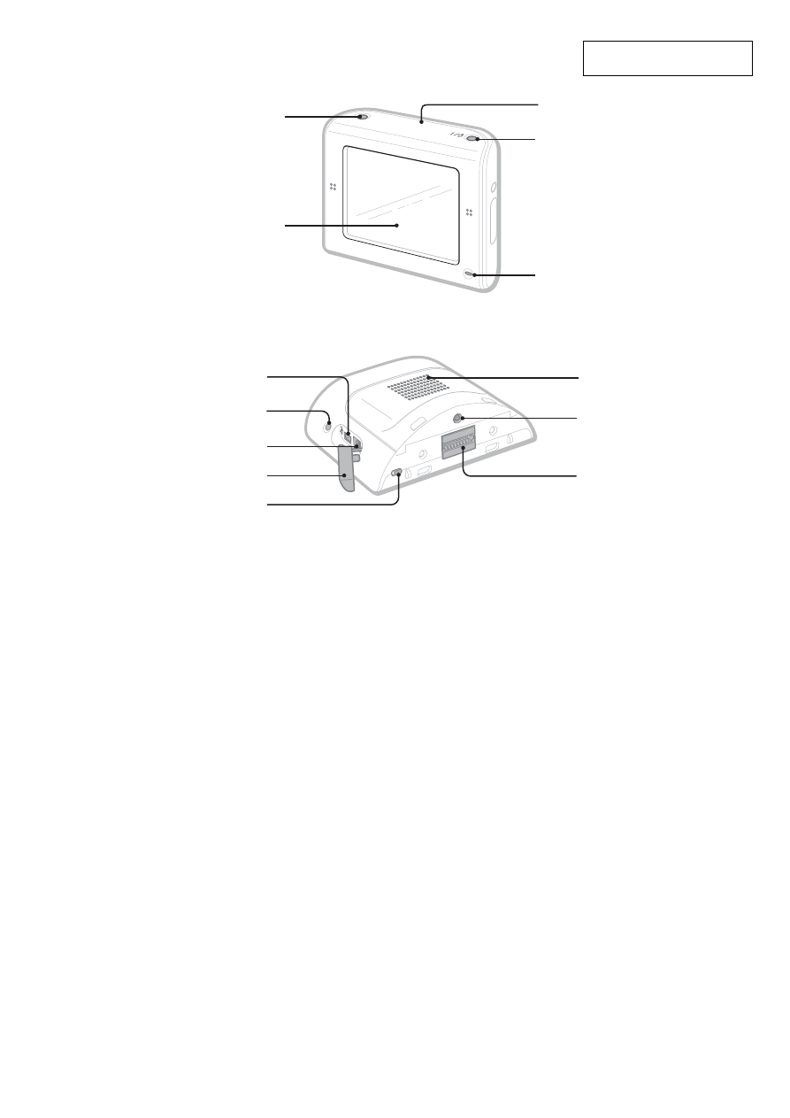
VOICE/POSITION button
During route guidance:
To hear the next voice guidance.
In the menu display:
To show the map.
In the map display:
To show your current car position.
2
Display window/touch screen
3
Built-in GPS antenna (aerial)
4 ?
/
1
(on/standby) button
To turn the unit on/off.
5
CHG (battery charge) indicator
Lights up in red while charging.
6
USB jack
To connect to a computer with the USB
cable.
7
Auto dimmer sensor
Detects ambient light and automatically
adjusts the display brightness.
8
DC IN 5V jack
To connect to the AC power adapter.
9
Jack cover
Note
If you pull off the jack cover by accident, use a
pointed object to push it back in.
q;
POWER switch
To turn the main power on/off; reset the unit.
qa
Speaker
Outputs guidance and warnings.
qs
External GPS antenna (aerial) jack
To connect the external GPS antenna (aerial) to the
cradle.
qd
Cradle connector
This section is extracted from
instruction manual.
4
NV-U51/U71T
1
DC IN
5.2V
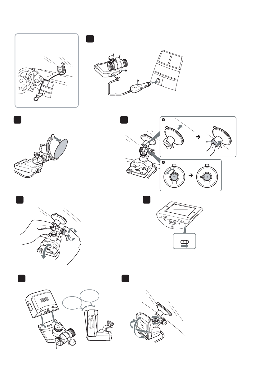
Windscreen installation
Installation an der Windschutzscheibe
Installation sur le pare-brise
Installatie op de voorruit
Note
Before attaching the suction cup, clean the attachment
surface.
Tip
Retain the removed protection sheet and attach it to the
suction cup when you detach the cradle from the windscreen
to keep the suction cup clean.
Hinweis
Reinigen Sie die Befestigungsstelle, bevor Sie den Saugnapf
anbringen.
Tipp
Nehmen Sie die Schutzfolie ab und heben Sie sie auf. Bringen
Sie die Schutzfolie wieder am Saugnapf an, wenn Sie die
Anschlussstation von der Windschutzscheibe abnehmen, um
den Saugnapf vor Verunreinigungen zu schützen.
Remarque
Avant de fi xer la ventouse, nettoyez la surface de fi xation.
Conseil
Conservez la feuille de protection que vous avez enlevée et
fixez-la à la ventouse lorsque vous détachez le support du
pare-brise, afi n de garder la ventouse propre.
Opmerking
Voordat u de zuignap bevestigt, moet u het
bevestigingsoppervlak reinigen.
Tip
Bewaar het verwijderde bevestigingsvel en bevestig dit op
de zuignap wanneer u de houder van de voorruit verwijdert
zodat de zuignap schoon blijft.
2
3
*
Press the button
completely.
*
Drücken Sie die Taste
ganz nach unten.
*
Appuyez à fond sur le
bouton.
*
Druk de toets volledig in.
CHG
POWER
OFF
ON
OFF
POWER
ON
Note
If you are concerned about car vibration and want to stabilize
the unit, cut the supplied pad
1
to the appropriate size and
attach it to the cradle bottom, to sit between the cradle and
dashboard.
Hinweis
Wenn Sie das Gerät stabilisieren und Erschütterungen
vom Fahrzeug abschwächen wollen, schneiden Sie die
mitgelieferte Unterlage auf die richtige Größe zu und
bringen Sie sie an der Unterseite der Anschlussstation an, so
dass sie zwischen Anschlussstation und Armaturenbrett sitzt.
Remarque
Si vous craignez des vibrations du véhicule et que vous
souhaitez stabiliser l’appareil, découpez le tampon fourni
1
à la taille appropriée et fi xez-le sur la partie inférieure du
support afi n qu’il se trouve entre le support et le tableau de
bord.
Opmerking
Als u zich zorgen maakt over de vibraties in de auto en het
apparaat wilt stabiliseren, knipt u het bijgeleverde kussentje
1
op het juiste formaat en bevestigt u dit aan de onderkant
van de houder, zodat het kussentje tussen de houder en het
dashboard bevindt.
4
5
See also “Turning the unit on” in the supplied Quick Start Guide.
Siehe auch „Einschalten des Geräts“ in der mitgelieferten Anleitung zur
schnellen Inbetriebnahme.
Consultez également la section « Mise en service de l’appareil » du
Guide de démarrage rapide fourni.
Raadpleeg ook "Het apparaat inschakelen" in de bijgeleverde Beknopte
handleiding.
1st click
2nd click
6
7
After the initial installation, park your car in
a safe, open place (no high buildings, etc.) for
up to 20 minutes to allow for GPS signals to be
received before using the navigation system.
Stellen Sie das Fahrzeug nach der
Anfangsinstallation bis zu 20 Minuten an
einer sicheren, offenen Stelle (keine hohen
Gebäude usw.) ab, damit die GPS-Signale
empfangen werden können, bevor Sie das
Navigationssystem in Betrieb nehmen.
Après l’installation initiale, garez votre voiture
dans un endroit sûr et dégagé (sans bâtiments
élevés, etc.) pendant 20 minutes environ
pour que les signaux GPS soient captés, avant
d’utiliser le système de navigation.
Na de installatie parkeert u de auto maximaal 20
minuten op een veilige, open plek (zonder hoge
gebouwen, enzovoort) zodat de GPS-signalen
kunnen worden ontvangen voordat u het
navigatiesysteem gebruikt.
5
NV-U51/U71T
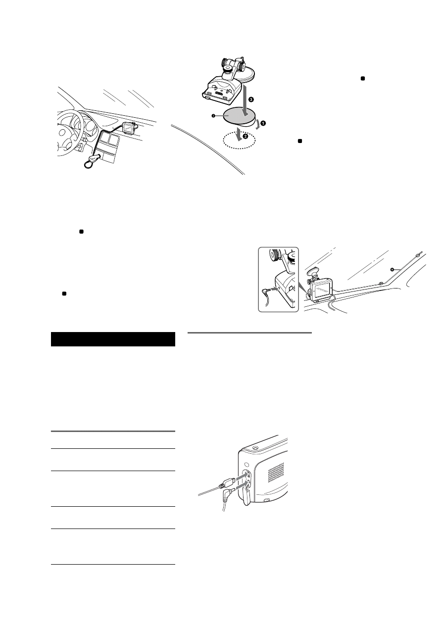
TMC aerial installation (NV-U71T only)
Install the supplied TMC aerial
H
to obtain traffic
information from RDS-TMC (Traffic Message
Channel).
Installation der TMC-Antenne (nur NV-U71T)
Installieren Sie die mitgelieferte TMC-Antenne
H
.
So können Sie Verkehrsinformationen über RDS-
TMC (Traffic Message Channel) empfangen.
Installation de l’antenne TMC
(modèle NV-U71T uniquement)
Installez l’antenne TMC
H
fournie afi n d’obtenir
des informations de radioguidage de RDS-TMC
(Traffic Message Channel, canal des messages de
radioguidage).
Installatie van de TMC-antenne
(alleen NV-U71T)
Installeer de bijgeleverde TMC-antenne
H
voor
verkeersinformatie van RDS-TMC (Traffic Message
Channel).
Dashboard installation
Installation am Armaturenbrett
Installation sur le tableau de bord
Installatie op het dashboard
Choose an attachment surface that is fl at, smooth
and as horizontal as possible, otherwise the cradle
may not attach properly.
Before attaching the supplied sheet
J
, clean the
attachment surface. Then, proceed from step
1
above.
Note
If you are concerned about car vibration and want to stabilize
the unit, cut the supplied pad
J
to the appropriate size and
attach it to the cradle bottom, to sit between the cradle and
dashboard.
Wählen Sie eine ebene, glatte und möglichst
waagrechte Befestigungsstelle. Andernfalls lässt
sich die Anschlussstation nicht richtig befestigen.
Reinigen Sie die Befestigungsstelle, bevor Sie die
mitgelieferte Folie
J
anbringen. Fahren Sie dann
mit Schritt
1
oben fort.
Hinweis
Wenn Sie das Gerät stabilisieren und Erschütterungen
vom Fahrzeug abschwächen wollen, schneiden Sie die
mitgelieferte Unterlage
J
auf die richtige Größe zu und
bringen Sie sie an der Unterseite der Anschlussstation an, so
dass sie zwischen Anschlussstation und Armaturenbrett sitzt.
Choisissez une surface de fi xation plate, lisse et
la plus horizontale possible, sans quoi le support
risque ne pas rester fi xé correctement.
Avant de fi xer la feuille
H
fournie, nettoyez la
surface de fi xation. Suivez ensuite la procédure à
partir de l’étape
1
ci-dessus.
Remarque
Si vous craignez des vibrations du véhicule et que vous
souhaitez stabiliser l’appareil, découpez le tampon fourni
H
à la taille appropriée et fi xez-le sur la par
support afi n qu’il se trouve entre le support et le tableau de
bord.
Kies een bevestigingsoppervlak dat vlak, egaal en
zo horizontaal mogelijk is, anders kan de houder
wellicht niet goed worden bevestigd.
Voordat u het bijgeleverde vel
H
u het bevestigingsoppervlak. Ga daarna verder
vanaf
1
hierboven.
Opmerking
Als u zich zorgen maakt over de vibraties in de auto en het
apparaat wilt stabiliseren, knipt u het bijgeleverde kussentje
H
op het juiste formaat en bevestigt u dit aan de onderkant
van de houder, zodat het kussentje tussen de houder en het
dashboard bevindt.
Using the Supplied Software
The major functions of the software on the
supplied CD-ROM are introduced below.
If you insert the CD-ROM into your computer,
the screen appears automatically. Follow the on-
screen instructions.
System requirements
• OS: Windows 2000/XP
• CD-ROM/DVD-ROM drive
• USB port
• 150 MHz CPU speed minimum
Contents
Connecting to your computer
Before connecting to your computer, install the
PC connection software (ActiveSync) to your
computer.
1
Connect the unit to an outlet using the
AC power adapter and the AC power
cable.
2
Connect the unit to your computer
with the USB cable.
Connect the small connector of the USB
cable to the USB jack on the unit, then the
large connector to a USB port on your
computer.
Notes when transferring data
During transfer, do not
– disconnect the USB cable or the AC power adapter.
– turn off the main power of the unit, enter unit standby
mode, or reset the unit.
– shut down the computer, enter computer standby
mode, or restart the computer.
If you want to cancel transferring mid-way, click the
cancel button on the computer screen.
Install PC Connection Software
PC connection software (ActiveSync) can be
installed.
Language Manager
Language data for on-screen display and voice
guidance can be added to the unit, and
unnecessary language data can be deleted from
the unit.
Read the Manual
You can read the PDF manual which contains
further information on operations available.
Support Link
Easy access to the Sony navigation support site is
available.
Visit this site for technical support, such as
software updates, FAQs, etc.
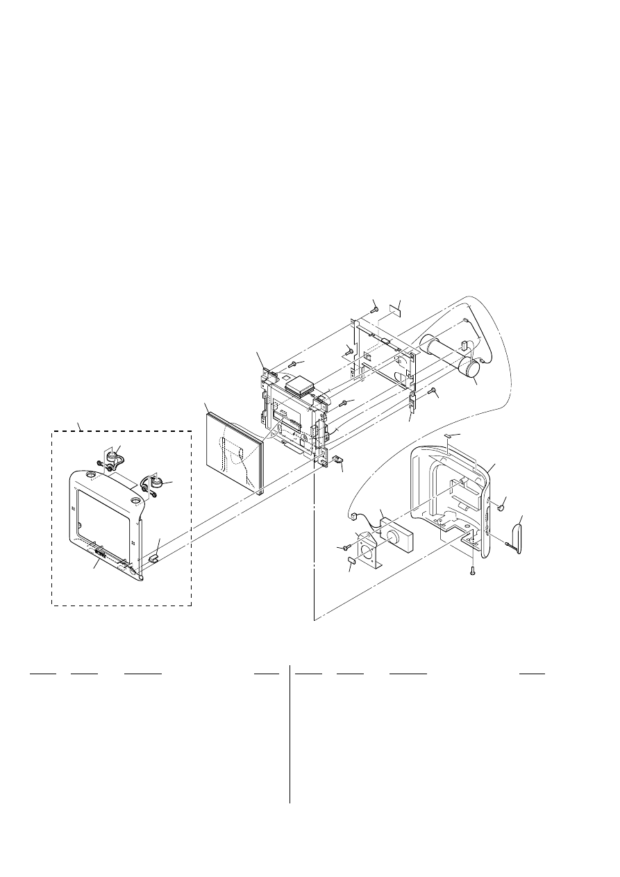
NV-U51/U71T
6
Note:
Follow the disassembly procedure in the numerical order given.
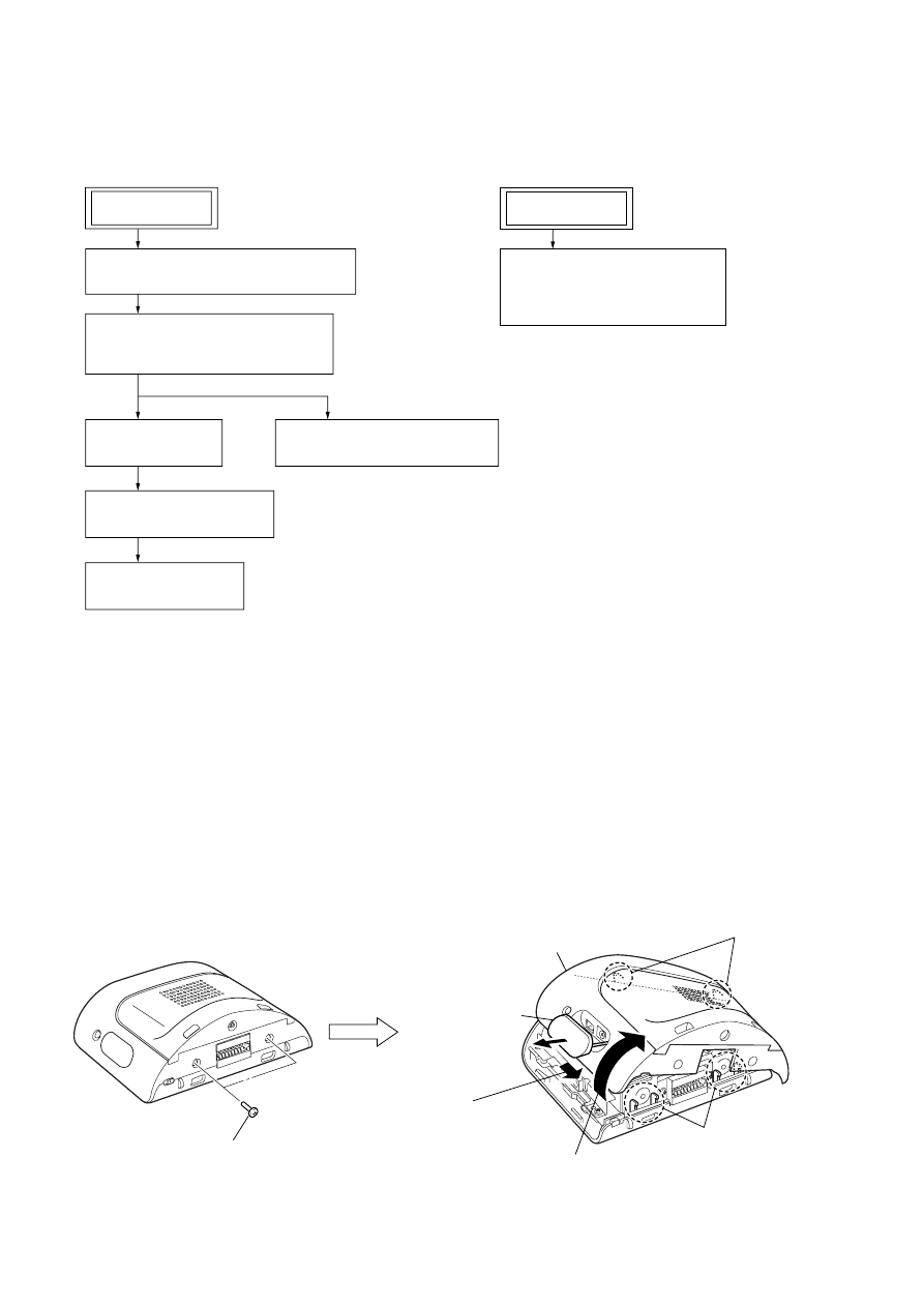
2-2. METHOD OF OPEN THE REAR PANEL
•
This set can be disassembled in the order shown below.
2-1. DISASSEMBLY FLOW
SECTION 2
DISASSEMBLY
2-2. METHOD OF OPEN THE REAR PANEL
(Page 6)
2-3. REAR PANEL BLOCK ASSY,
BATTERY BLOCK ASSY (BAT5001)
(Page 7)
2-4. SHIELD PLATE
(Page 7)
2-7. SPEAKER (2
×
4 cm) (SP3001)
(Page 9)
2-5. CHASSIS BLOCK ASSY
(Page 8)
2-6. LCD BLOCK ASSY
(Page 8)
2-8. CASE (UPPER) BLOCK ASSY,
CASE (LOWER) BLOCK ASSY
(NVA-CU4/CU4T)
(Page 9)
SET (CRADLE)
SET (MAIN UNIT)
1
two screws
(PTT2.6
×
4)
2
Open the
connector cover.
3
Slide the
rear panel (six claws).
four claws
two claws
4
Lift to open the rear panel.
rear panel
NV-U51/U71T
7
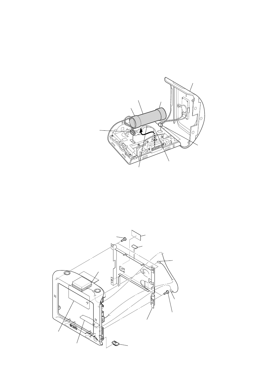
2-3. REAR PANEL BLOCK ASSY, BATTERY BLOCK ASSY (BAT5001)
2-4. SHIELD PLATE
1
connector
(CN3002)
cushion (E)
coaxial connector lead wire
3
connector
(CN5002)
2
rear panel block assy
4
battery block assy
(BAT5001)
Note: When the Battery Block Assy (BAT5001) is installed,
route coaxial connector lead wire from the SUB Board and
lead wire from the GPS Antenna (ANT8001) so that they do not ride on the Cushion (E).
cushion (E)
GPS antenna (ANT8001) lead wire
4
two screws
(B2.6
×
6)
5
two screws (T)
8
shield plate
6
gasket (SP)
3
GPS antenna (ANT8001) lead wire
(CN8001)
2
coaxial connector lead wire
(GPS unit (CP8001))
1
switch (PW)
7
license label
GPS unit
(CP8001)
GPS antenna
(ANT8001)
SUB board
NV-U51/U71T
8
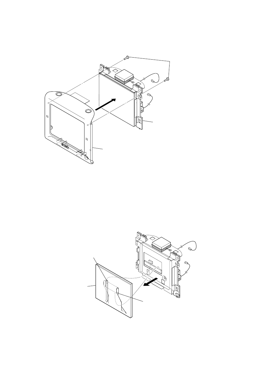
2-5. CHASSIS BLOCK ASSY
2-6. LCD BLOCK ASSY
1
two screws
(B2.6
×
6)
2
chassis block assy
3
front panel block assy
2
1
touch panel switch flexible board
(CN6001)
3
liquid crystal display panel flexible board
(CN6002)
4
LCD block assy
Note: Please work noting that the
LCD block assy is damaged.
NV-U51/U71T
9
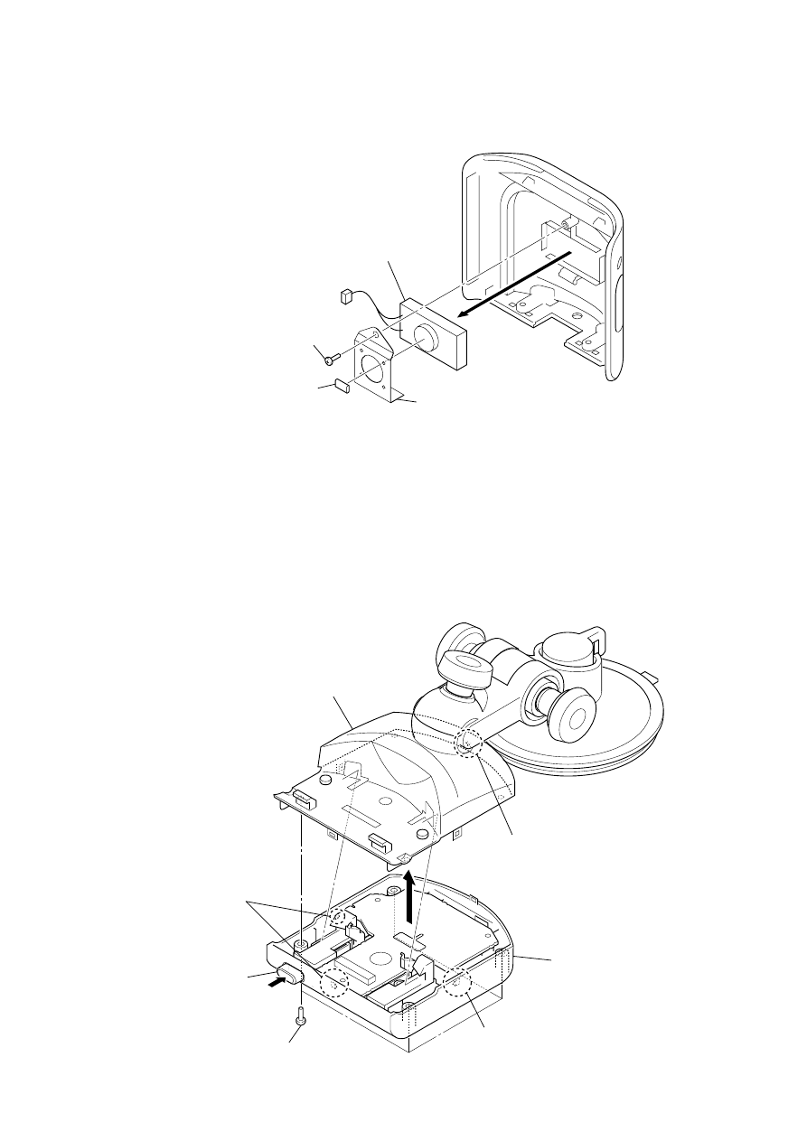
2-7. SPEAKER (2
×
4 cm) (SP3001)
2
two screws
(B2.6
×
6)
4
speaker (2
×
4 cm)
(SP3001)
3
speaker holder
1
gasket (SP)
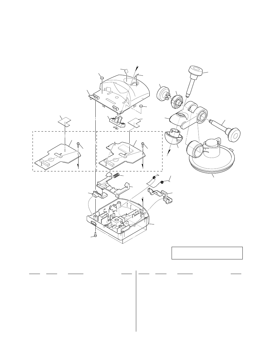
2-8. CASE (UPPER) BLOCK ASSY, CASE (LOWER) BLOCK ASSY
(NVA-CU4/CU4T)
1
four screws
(B2
×
5)
button (release)
2
claw
4
While pushing the button (release),
remove the case (upper) block assy.
5
case (lower) block assy
3
claw
2
two claws
10
NV-U51/U71T
SECTION 3
EXPLODED VIEWS
Ref. No.
Part No.
Description
Remark
Ref. No.
Part No.
Description
Remark
1
A-1205-632-A PANEL BLOCK ASSY, FRONT
(U51: A, B, D, F, G, N, S/U71T: US, CND)
1
A-1217-198-A PANEL BLOCK ASSY, FRONT (U51: I)
1
A-1217-201-A PANEL BLOCK ASSY, FRONT (U71T: AEP, UK)
2
2-693-111-01 INDICATOR
3
2-693-109-01 BUTTON PW (L)
4
2-693-110-01 BUTTON PW (R)
5
A-1217-520-A LCD BLOCK ASSY
6
2-650-655-02 SWITCH (PW)
7
2-055-460-01 SPECIAL SCREW (2.6X6, B)
8
3-042-244-01 SCREW (T)
9
2-693-108-01 PANEL, REAR (U51: A, B, D, F, G, N, S/U71T:
US, CND)
9
2-693-108-11 PANEL, REAR (U71T: AEP, UK)
9
2-693-108-21 PANEL, REAR (U51: I)
10
2-650-662-02 WINDOW
11
2-650-661-02 COVER, CONNECTOR
BAT5001 A-1205-775-A BATTERY BLOCK ASSY (U51/U71T: AEP, UK)
BAT5001 A-1205-776-A BATTERY BLOCK ASSY (U71T: US, CND)
SP3001 1-826-490-21 SPEAKER (2X4 cm)
#1
7-685-790-01 SCREW +PTT 2.6X4 (S)
•
Items marked “*” are not stocked since they
are seldom required for routine service. Some
delay should be anticipated when ordering
these items.
•
The mechanical parts with no reference
number in the exploded views are not supplied.
NOTE:
•
-XX and -X mean standardized parts, so they
may have some difference from the original
one.
•
Color Indication of Appearance Parts
Example:
KNOB, BALANCE (WHITE) . . . (RED)
↑
↑
Parts Color
Cabinet's Color
not supplied
1
#1
not supplied
not supplied
not supplied
not
supplied
not supplied
BAT5001
SP3001
not supplied
2
3
4
5
6
7
7
7
7
7
8
9
10
11
•
Abbreviation
A
: NV-U51A
B
: NV-U51B
CND : Canadian model
D
: NV-U51D
F
: NV-U51F
G
: NV-U51G
I
: NV-U51I
N
: NV-U51N
S
: NV-U51S
3-1.
MAIN UNIT SECTION
11
NV-U51/U71T
3-2.
CRADLE SECTION
(NVA-CU4
: for NV-U51)
(NVA-CU4T : for NV-U71T)
Ref. No.
Part No.
Description
Remark
Ref. No.
Part No.
Description
Remark
101
X-2103-070-3 CASE (CR ) (LOWER) ASSY (U51)
101
X-2103-082-3 CASE (CR) (LOWER) M ASSY (U71T)
102
2-650-774-03 BUTTON (RELEASE)
103
2-650-773-02 LEVER (LOCK)
104
2-650-775-11 SPRING (RELEASE), COMPRESSION
105
A-1177-653-A CRADLE BOARD, COMPLETE (U51)
105
A-1177-924-A CRADLE BOARD, COMPLETE (U71T)
106
3-719-601-61 SCREW (B2X5), TAPPING
107
2-650-771-03 CASE (CR) (UPPER)
108
3-266-982-11 SPACER (MC)
109
2-662-294-01 SHEET (BALL ARM)
110
2-650-777-11 SPRING (EJECT), TORSION COIL
111
2-650-776-02 LEVER (EJECT)
112
2-650-780-03 ARM (LOWER), BALL
113
2-650-779-03 ARM (UPPER), BALL
114
2-650-788-02 CLUTCH (DIAL)
115
2-650-787-02 DIAL (SUCTION CUP)
116
2-650-785-01 DIAL (BALL JOINT)
117
A-1205-634-A SUCKER BLOCK ASSY
118
2-650-782-01 NUT, BALL
119
2-650-778-11 SHEET (CR), INSULATING
#2
7-624-106-04 STOP RING 3.0, TYPE-E
101
#2
(U51)
(U71T)
102
103
104
106
106
106
105
105
107
108
108
109
109
110
111
112
113
114
115
116
116
118
119
119
B
B
B
A
A
117
Note: When CRADLE board is defective,
exchange the entire mounted board.
Ref. No.
Part No.
Description
Remark
Ref. No.
Part No.
Description
Remark
12
NV-U51/U71T
ACCESSORIES
************
2-886-305-12 MANUAL, INSTRUCTION (Quick Start Guide)
(ENGLISH, FRENCH, SPANISH) (U71T: US, CND)
2-886-305-22 MANUAL, INSTRUCTION (Quick Start Guide)
(ENGLISH, GERMAN, FRENCH, DUTCH,
ITALIAN, SPANISH, SWEDISH, PORTUGUESE)
(U51/U71T: AEP, UK)
2-886-306-12 MANUAL (READ THIS FIRST) (ENGLISH,
FRENCH, SPANISH) (U71T: US, CND)
2-886-306-22 MANUAL (READ THIS FIRST)
(ENGLISH, FRENCH, GERMAN, DUTCH)
(U51/U71T: AEP, UK)
2-886-306-32 MANUAL (READ THIS FIRST)
(SPANISH, PORTUGUESE, ITALIAN, SWEDISH)
(U51: A, I, N, S/U71T: AEP, UK)
*************************************************************
SECTION 4
ACCESSORIES
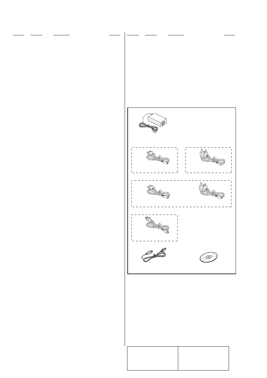
PARTS FOR INSTALLATION AND CONNECTIONS
(for MAIN UNIT)
**************************************
0 501
1-479-621-31 ADAPTOR, AC (AC power adaptor) (XA-AC13)
0 502
1-827-481-21 POWER-SUPPLY CORD (for AC power adaptor)
(U51: A, B, D, F, I, N, S/U71T: AEP, UK)
0 503
1-827-946-31 CORD, POWER (for AC power adaptor)
(U51: G/U71T: AEP, UK)
0 504
1-829-809-11 CORD, POWER (for AC power adaptor)
(U71T: US, CND)
505
1-827-038-11 CORD, CONNECTION (USB 5P) (USB cable)
506
2-892-426-01 DISC, APPLICATION
(Application disc (CD-ROM))
•
Abbreviation
A
: NV-U51A
B
: NV-U51B
CND : Canadian model
D
: NV-U51D
F
: NV-U51F
G
: NV-U51G
I
: NV-U51I
N
: NV-U51N
S
: NV-U51S
The components identified by
mark 0 or dotted line with mark
0 are critical for safety.
Replace only with part number
specified.
Les composants identifiés par
une marque 0 sont critiquens
pour la sécurité.
Ne les remplacer que par une
pièce portant le numéro spécifié.
501
AC POWER ADAPTOR (XA-AC13)
×
1
502
503
AC POWER CABLE
×
1
AC POWER CABLE
×
1
502
504
503
AC POWER CABLE
×
1
AC POWER CABLE
×
1
(U71T: AEP, UK)
(U71T: US, CND)
(U51: G)
505
AC POWER CABLE
×
1
USB CABLE
×
1
506
(U51: A, B, D, F, I, N, S)
APPLICATION DISC (CD-ROM)
×
1
Ref. No.
Part No.
Description
Remark
Ref. No.
Part No.
Description
Remark
13
NV-U51/U71T
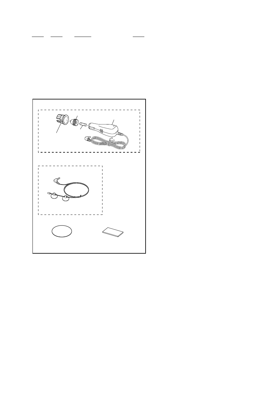
PARTS FOR INSTALLATION AND CONNECTIONS (for CRADLE)
**************************************
511
1-831-550-31 CORD (WITH CIGAR LIGHTER PLUG)
(Car battery adaptor) (XA-DC2)
512
9-885-110-39 SPACER, PLUG
513
1-833-592-11 CORD, CONNECTION (ANTENNA)
(TMC antenna (aerial)/suction cups) (U71T)
514
2-891-214-01 SHEET (DASH BOARD), PROTECTION
515
2-655-124-11 CUSHION (CR) (Pad)
F1001
9-885-100-13 FUSE (CIS2.5A/125V)
not supplied
not supplied
F1001
511
512
513
514
515
CAR BATTERY ADAPTOR (XA-DC2)
×
1
PAD
×
1
PROTECTION SHEET
(DASH BOARD)
×
1
PLUG SPACER
×
1
TMC ANTENNA (AERIAL)
×
1/
SUCTION CUPS
×
2
(U71T)

2
NV-U51/U71T
REVISION HISTORY
Clicking the version allows you to jump to the revised page.
Also, clicking the version at the upper right on the revised page allows you to jump to the next revised
page.
Ver.
Date
Description of Revision
1.0
2006.11
New
Wyszukiwarka
Podobne podstrony:
NV U51 U71 montaz i?montaz
Instrukcja do ćw 18 Montaż i demontaż magazynu składowania MPS
5 Montaż i demontaż rączki pokrywy silnika
2 Montaż i demontaż trójkątnych elementów środkowy tunel
Montaż i demontaż elementów i podzespołów urządzeń i systemów mechatronicznychu
Montaż, demontaż stojaków oraz wymiana podzespołów sekcji
Montaż demontaż regeneracja
Montaż, demontaż stojaków oraz wymiana podzespołów sekcji 2
10 Montaż i demontaż uchwytów w podsufitówce ze standardu na GTI
Montaż i Demontaż, Sprawozdania
08 Wykonywanie montażu i demontażu silnika dwusuwowego
12 Wykonywanie montażu i demontażu kół samochodowych
montaz i demontaż łożysk
Montaż demontaż głośników tył LI HB
Instrukcja do ćw 19 Montaż i demontaż modułu „ stół obrotowy” MPS
09 Wykonywanie montażu i demontażu silnika czterosuwowego
12 Montaż i demontaż popielniczki środkowy tunel
więcej podobnych podstron