253
In This Chapter
12
Creating Parts
This tutorial continues with techniques you learned in
previous lessons. You use sketches to create features.
You position standard features, such as holes, and then
combine them to create a part. You analyze your design
and build a model so that you can easily incorporate
changes. This is a problem-solving process that you
can apply to any parts you create using Autodesk
®
Mechanical Desktop
®
.
In this tutorial, you create a saddle bracket in two
phases. First, you create all the features of the part in
rough form. Then, you refine those features to complete
the part.
■
Analyzing design ideas to simplify
sketching
■
Selecting the base feature
■
Planning the order in which to
add features
■
Stabilizing features with
constraints and dimensions
■
Creating features that remain
fixed relative to work planes and
work axes
■
Refining features
■
Adjusting features according to
design changes

254
|
Chapter 12
Creating Parts
Key Terms
Term
Definition
base feature
The first feature you create. As the basic element of your part, it represents its
simplest shape. All geometry you create for a part depends on the base feature.
consumed sketch
A sketch used in a feature, for example, an extruded profile sketch. The sketch is
consumed when the feature is created.
Desktop Browser
A graphical representation of the features that make up your model. You can work
in the Browser to create and restructure parts and assemblies, define scenes,
create drawing views, and control overall preferences.
placed feature
A mechanical shape that does not require sketches, such as a hole, chamfer, or
fillet. Placed features are constrained to the feature on which they are placed and
are geometrically dependent.
sketch plane
A temporary drawing surface that corresponds to a real plane on a feature. It is an
infinite plane with both X and Y axes, where you sketch or place a feature.
sketched feature
A three-dimensional solid whose shape is defined by constrained sketches and
located parametrically on a part. Sketched features are extrudes, lofts, revolves,
sweeps or face splits.
work axis
A parametric construction line created along the centerline of a cylindrical feature,
or sketched on the current sketch plane. A work axis can be used as the axis of
revolution for a revolved or swept feature, an array of features, to place a work
plane, and to locate new sketch geometry. It can be included in dimensions.
work feature
A work axis, work point, or work plane used to construct and position a feature
where there is no face on which to sketch or place the feature. You constrain or
dimension work features to maintain symmetry throughout updates.
work plane
An infinite plane attached to a part. Can be designated as a sketch plane and can
be included in a constraint or dimension scheme. Work planes can be either
parametric, or non-parametric.
work point
A parametric work feature used to position a hole, the center of an array, or any
other point for which there is no other geometric reference.
Basic Concepts of Creating Parts
|
255
Basic Concepts of Creating Parts
You construct a model bit by bit, fashioning shapes to add to it and using
tools to cut away the portions of the shapes you do not need. In Mechanical
Desktop
®
, these shapes are the features of the part you are creating.
Analyzing Rough Sketches
You may be accustomed to jotting down design ideas on paper, starting with
a rough outline for a part and adding details as you go. Working with
Mechanical Desktop is similar: you put some thought into your idea, plan-
ning the best way to implement your concept.
In general, you follow this process to develop a part design:
■
Look at the whole part and decide how to break it down into simple shapes.
■
Identify the simplest element to use as your base feature.
■
Decide the order for creating additional features.
■
Determine the methods for creating the features.
■
As you build individual features, review and adjust your ideas about how
the features work together.
■
As you adjust your design strategy, you can revise the features you created
earlier.
With early planning, you can express your design in modular, simple terms.
When changes occur, as they often do in design work, you can easily accom-
modate them because of the parametric capabilities in Mechanical Desktop.
Any changes you make to your design are quickly recalculated.
As you study the part to determine the features you need and the order in
which to create them, also notice the relationships and patterns of the
shapes. Some features may be symmetrical, but others may be built most eas-
ily from simple shapes combined to form compound shapes.
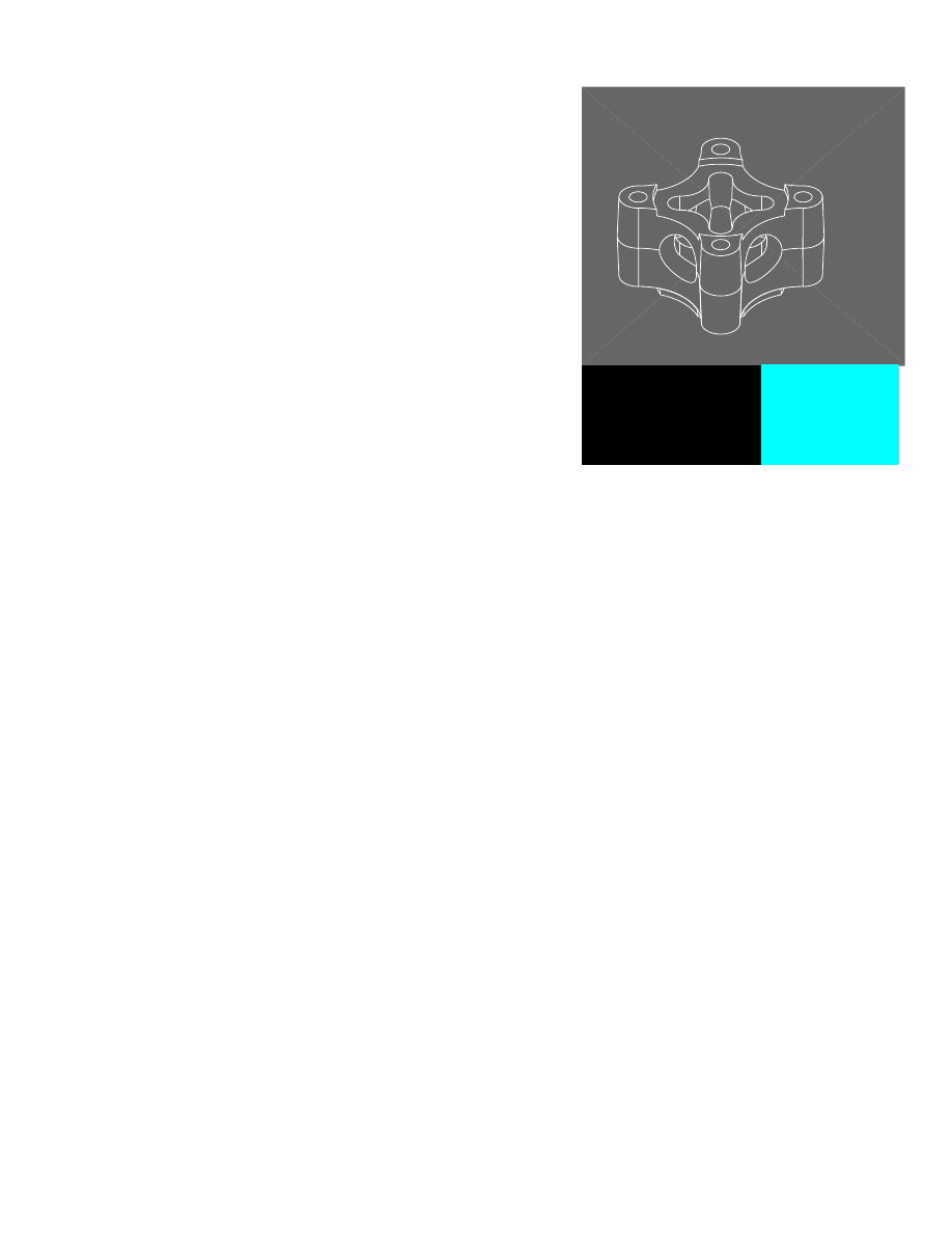
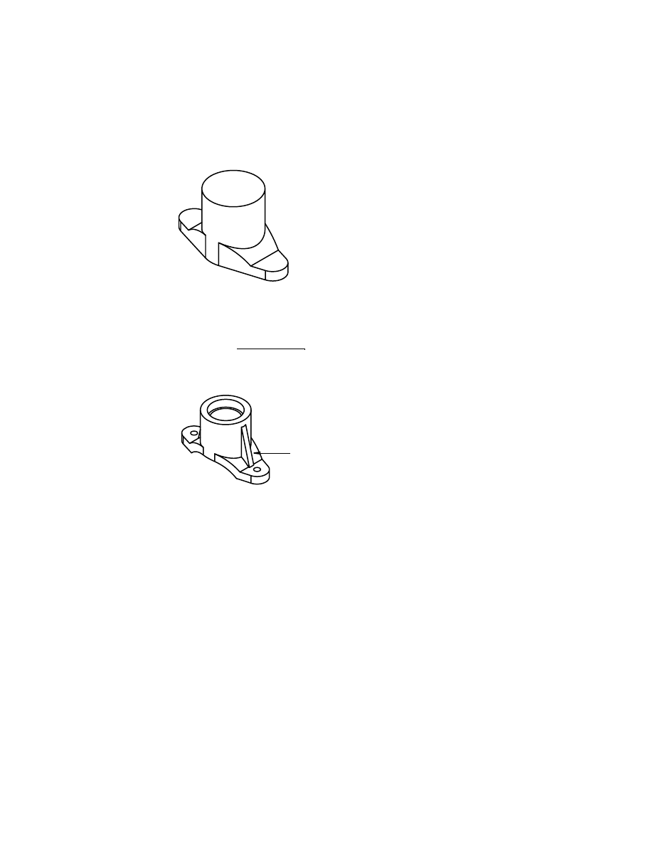
The saddle bracket in this rough sketch has four distinct features: the saddle,
the mounting lugs, a boss, and strengthening ribs.
lug
boss
saddle
rib
256
|
Chapter 12
Creating Parts
The part is symmetrical. Visualize two perpendicular centerlines—one along
the axis of the boss and another intersecting both lugs. As you create this
part, consider this symmetry as you constrain features.
As you build the saddle bracket, you learn to create features according to
the relationships among them. In this case, the base feature of the part is
the saddle and lugs. Because the remaining features attach to the saddle and
lugs, you create the main shape first. The next feature you create is the boss
because it rests directly on the saddle. Finally, you create the ribs because
they attach to both the saddle and the boss.
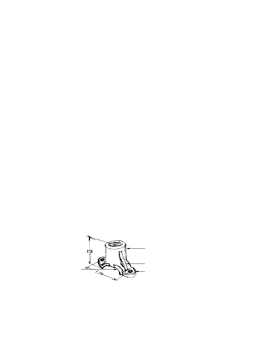
Creating Rough Parts
In the saddle bracket, features are present but lack details such as the arch of
the saddle, the mounting holes for the lugs, and the pipe hole for the boss.
Despite the missing details, the shape of the part and the placement of fea-
tures are symmetrical. Working from this basic part, you will add those
details.
Dimensioning and Constraining Parts
You apply dimensions and constraints to control the size and shape of a part,
and the position of part features. Dimensions can be expressed as numbers,
parameters, or equations.
You can use the Design Variables dialog box to create equations and control
the relationships between the dimensions on your model. Then you apply
the variables to your model and the model is updated to reflect the changes.
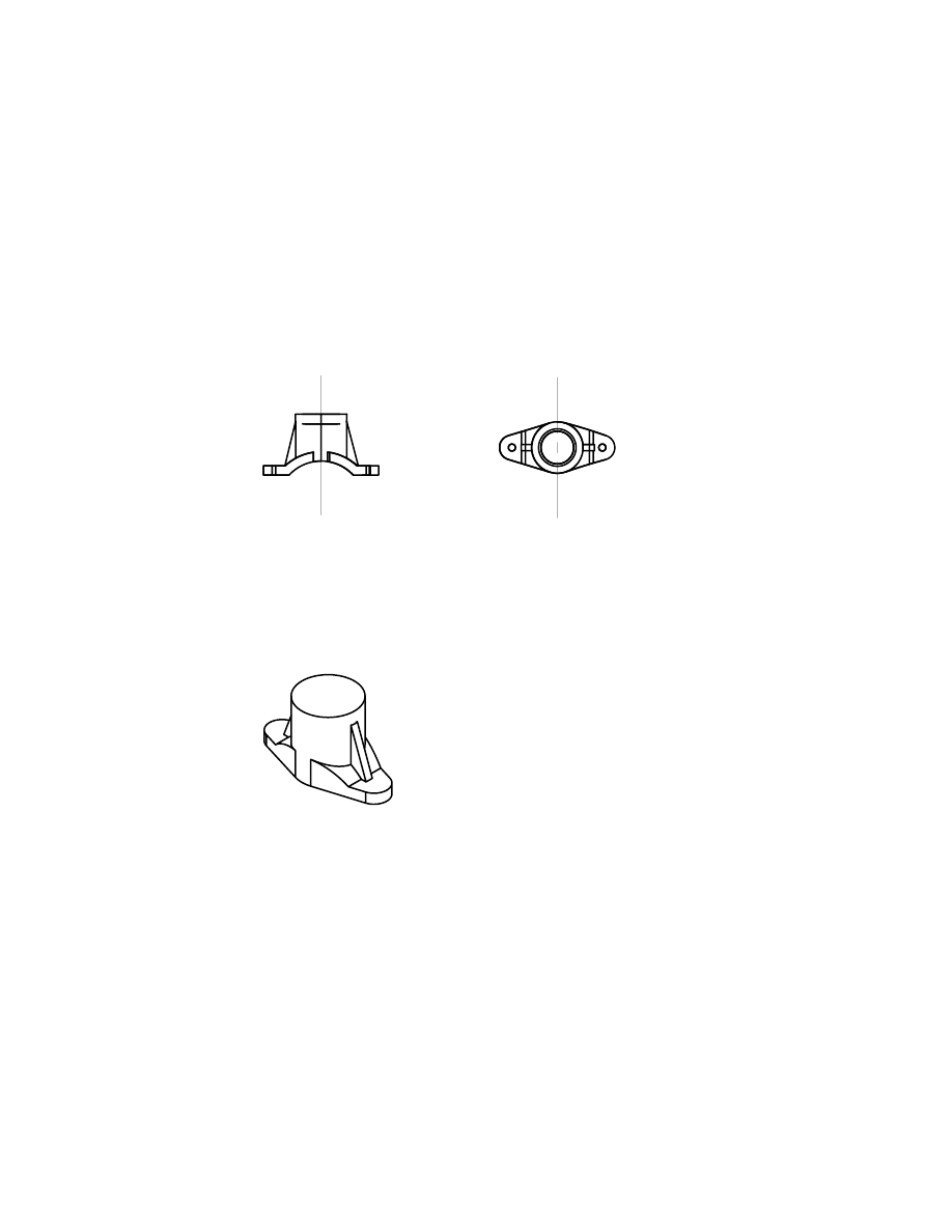
front view
top view
Creating Base Features
|
257
If you want to assign design variables as you are defining part sketches and
creating features, use the Equation Assistant. You can activate the Equation
Assistant in two ways:
■
When you are prompted for a dimension value, right-click the graphics
area.
■
While you are creating sketched and placed features, in the feature dialog
box, right-click a value field.
For more information about working with design variables, see “Using
Design Variables” on page 239.
To begin this lesson, open the file saddle.dwg in the desktop\tutorial folder.
The drawing is blank but contains the settings you need for this tutorial.
NOTE
Back up the tutorial drawing files so you still have the original files if you
make a mistake. See “Backing up Tutorial Drawing Files” on page 40.
Creating Base Features
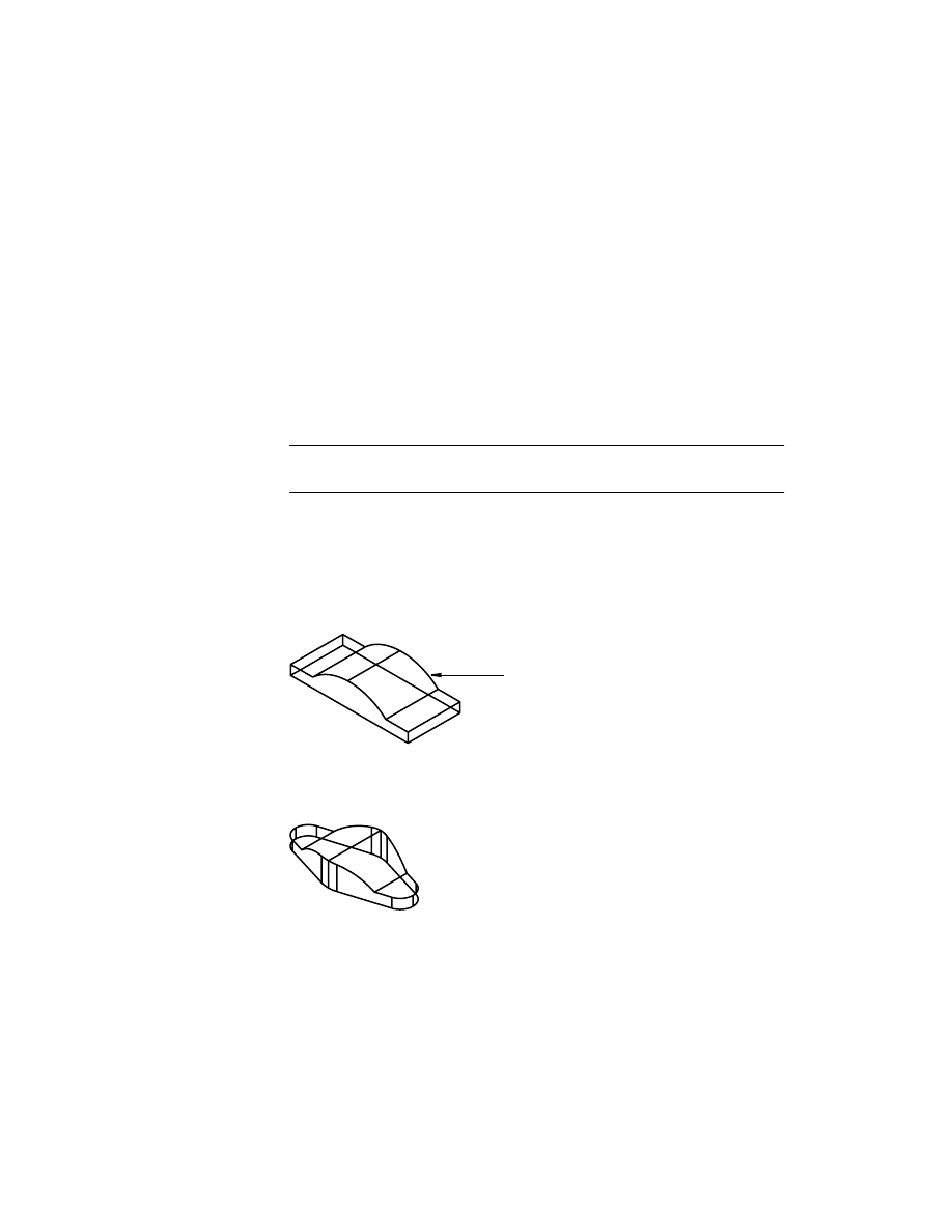
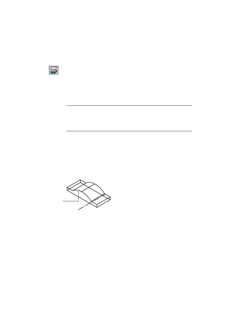
The overall shape of the saddle bracket is simple. First, you sketch a shape to
represent the saddle and lugs.
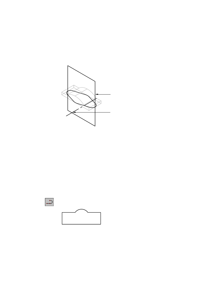
Next, you convert the sketch to a base feature and modify its shape by inter-
secting it with a second feature. Intersecting the base feature is like cutting
away material you don’t need.
saddle arch
258
|
Chapter 12
Creating Parts
When you create these features, you position them symmetrically using a
work axis and a work plane. Like other features, you include work features in
your constraint scheme to maintain symmetry throughout future updates to
the part.
Sketching Base Features
After you have a strategy, you are ready to sketch, constrain, and extrude the
base feature of the part. Begin by creating a sketch of the block and then con-
verting it to a profile sketch.
To make it easier to sketch the shape, turn off Polar, Osnap, and Otrack at the
bottom of your screen.
To create a profile sketch
1
Use
PLINE
to sketch this shape. Draw the shape starting at the lower left of
the sketch.
You can use the cursor crosshairs to align the top horizontal lines (that is,
make them collinear). Use the Direction option of
PLINE
to control the direc-
tion of the arc.
Context Menu
In the graphics area, right-click and choose 2D Sketching
➤ Polyline.
work plane
work axis
Creating Base Features
|
259
2
Use
AMPROFILE
to profile your sketch.
Context Menu
In the graphics area, right-click and choose Sketch Solving
➤ Single Profile.
Mechanical Desktop analyzes the sketch and displays a message on the com-
mand line:
Solved underconstrained sketch requiring 5 dimensions or constraints.
NOTE
Throughout this tutorial, the number of constraints your sketch needs
may differ from the example, depending on how precisely you draw the sketch.
You learn how to modify constraints so that your sketch solves correctly.
Look at the assumed constraints and determine which constraints you need.
3
Use
AMSHOWCON
to display all of the existing constraints.
Context Menu
In the graphics area, right-click and choose 2D
Constraints ➤ Show Constraints.
Respond to the prompt to show all constraints.
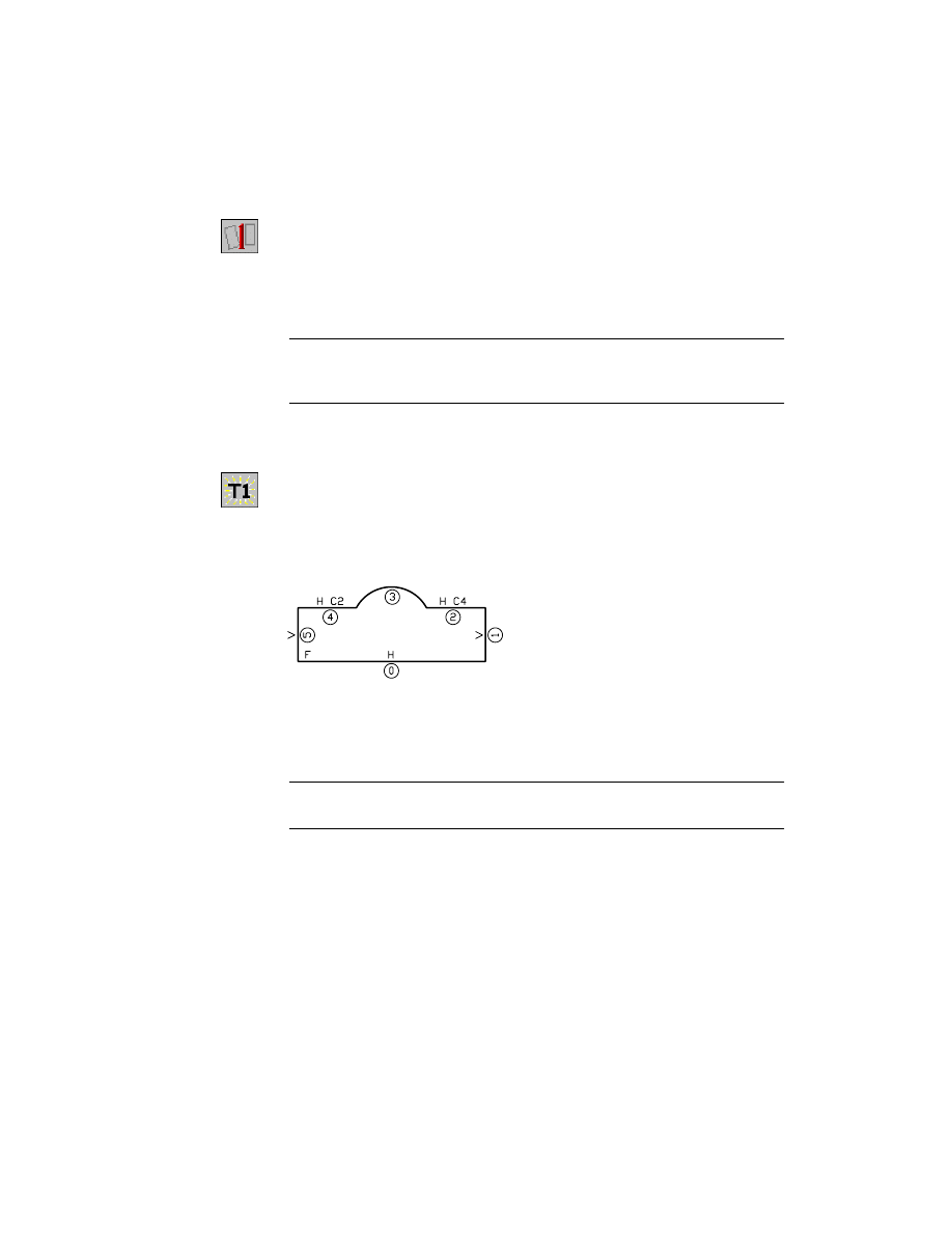
Your sketch should look like this. However, the constraint numbering may
differ, depending on the order in which you drew the geometry.
In the example, all sketch elements have constraints except the arc. The lines
show vertical (V) or horizontal (H) constraints and the top two horizontal
lines show a collinear (C) constraint. A fix constraint is located at the start
point of line 0.
NOTE
If the fix constraint in your sketch does not appear in the same location
as the illustration above, redraw the sketch starting at the lower left.
Now that the basic sketch shape is defined, you need to add dimensions to
stabilize its size. Start with its longest lengths to minimize the risk of distort-
ing the shape as it is resized.
260
|
Chapter 12
Creating Parts
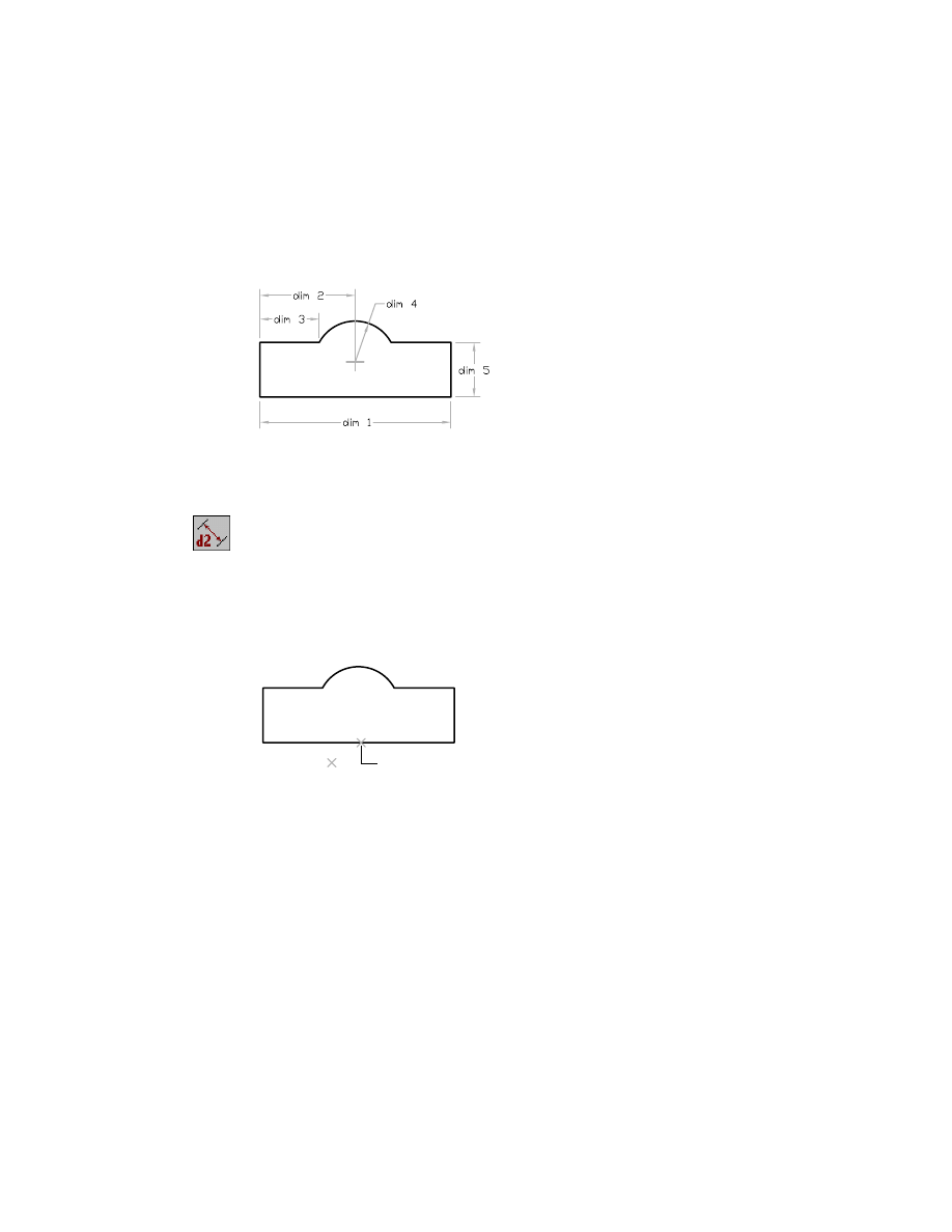
For this exercise, add dimensions in the order shown, starting with the
dimension for the bottom line.
Depending on your sketch, your default dimension values may differ from
those in this exercise.
To constrain a sketch
1
Use
AMPARDIM
to add parametric dimensions to fully constrain the sketch,
following the prompts.
Context Menu
In the graphics area, right-click and choose Dimensioning
➤ New Dimension.
Select first object:
Specify the line (1)
Select second object or place dimension:
Place the dimension (2)
Enter dimension value or [Undo/Hor/Ver/Align/Par/aNgle/Ord/Diameter/pLace]
<1.2297>:
Enter 1.48
Solved underconstrained sketch requiring 4 dimensions or constraints.
2
To center the arc, create a horizontal dimension from the center of the arc to
the left edge of the sketch.
Select first object:
Specify the left edge (1)
Select second object or place dimension:
Specify the arc (2)
Specify dimension placement:
Place the dimension (3)
Enter dimension value or [Undo/Hor/Ver/Align/Par/aNgle/Ord/Diameter/pLace]
<0.5944>:
Enter .74
Solved underconstrained sketch requiring 3 dimensions or constraints.
1
2
Creating Base Features
|
261
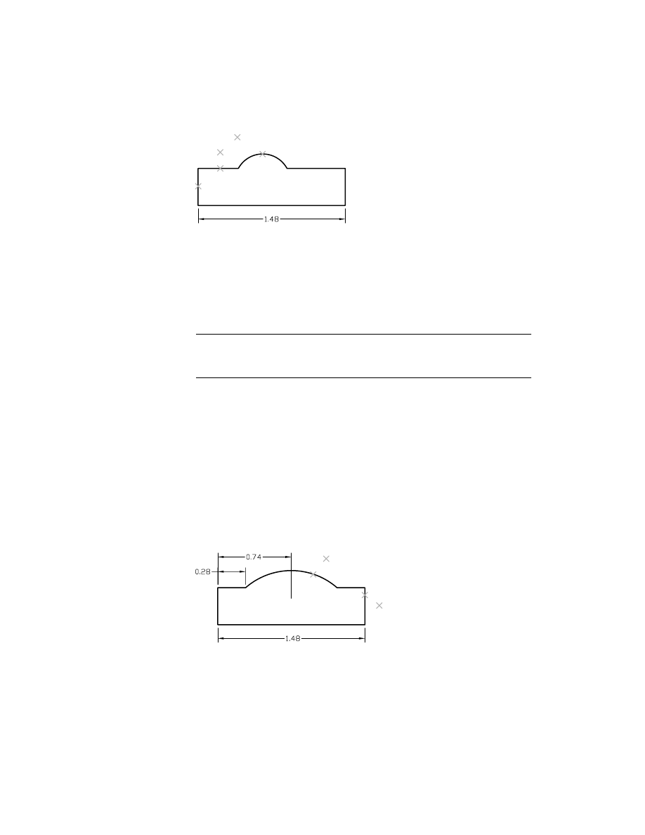
3
Create the dimension for the top left horizontal line. Continue to follow the
selection points.
Select first object:
Specify the left horizontal line (4)
Select second object or place dimension:
Place the dimension (5)
Enter dimension value or [Undo/Hor/Ver/Align/Par/aNgle/Ord/Diameter/pLace]
<0.3951>:
Enter .28
Solved underconstrained sketch requiring 2 dimensions or constraints.
NOTE
You may get a message stating that adding a dimension will overcon-
strain the sketch. This can occur if your sketch does not closely resemble this
exercise. Try adding the dimensions in a different order, or re-create your sketch.
4
Finish dimensioning the sketch.
Select first object:
Specify the arc (1)
Select second object or place dimension:
Place the dimension (2)
Enter dimension value or [Undo/Diameter/Ordinate/Placement point]
<0.4600>:
Enter .68
Solved underconstrained sketch requiring 1 dimensions or constraints.
Select first object:
Specify the line on the right (3)
Select second object or place dimension:
Place the dimension (4)
Enter dimension value or [Undo/Hor/Ver/Align/Par/aNgle/Ord/Diameter/pLace]
<0.2176>:
Enter .20
Solved fully constrained sketch.
Select first object:
Press
ENTER
Now that your profile sketch is fully constrained, create a solid feature.
2
4
3
5
1
3
4
1
2
262
|
Chapter 12
Creating Parts
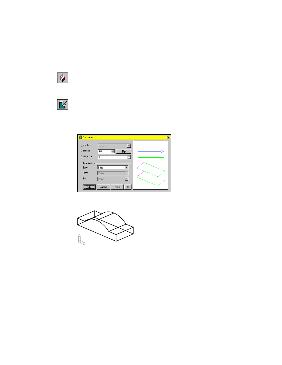
To extrude a feature
1
Change to an isometric view of your part.
Desktop Menu
View ➤ 3D Views ➤ Front Right Isometric
You need to specify the type of extrusion operation, how to terminate the
extrusion, and its size.
2
Use
AMEXTRUDE
to extrude the profile.
Context Menu
In the graphics area, right-click and choose Sketched &
Work Features ➤ Extrude.
3
In the Extrusion dialog box, specify:
Distance:
.66
Termination:
Blind
Choose OK to create the feature.
The base feature should look like this.
4
Refer to the Desktop Browser, which shows that you have added an extrusion
feature to the base feature and that the extrusion was blind (a specific depth).
Click the plus sign beside the extrusion feature to display a profile icon. This
display tells you that the extrusion feature originated with the profiled
sketch. If you complete a feature and then need to change its size or shape,
you can edit it and update the part to reflect the change.
Creating Base Features
|
263
To edit a consumed sketch in the Browser, double-click the profile icon to dis-
play the original sketch, or right-click to show the menu, and choose Edit
Sketch. Make any changes and choose Part ➤ Update to resize the part with
the changed values.
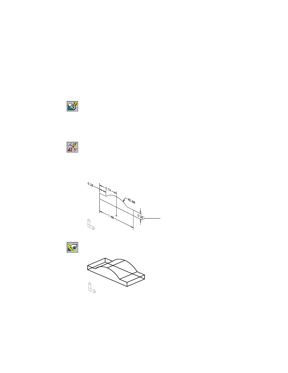
To edit a base feature
1
Select the sketch to edit, responding to the prompts.
Context Menu
In the graphics area, right-click and choose Edit Features
➤ Edit.
Enter an option [Independent array instance/Sketch/surfCut/Toolbody/select
Feature] <select Feature>:
Enter s
Select sketched feature:
Specify the extrusion
2
Modify the height of the sketch, responding to the prompts.
Context Menu
In the graphics area, right-click and choose Dimensioning
➤ Edit Dimension.
Select dimension to change:
Select the 0.20 dimension (1)
New value for dimension <.20>:
Enter .12
Solved fully constrained sketch.
Select dimension to change:
Press
ENTER
3
Use
AMUPDATE
to update the model, responding to the prompt.
Context Menu
In the graphics area, right-click and choose Update Part.
Your part is updated according to the changed dimension and looks like this.
Save your file.
1
264
|
Chapter 12
Creating Parts
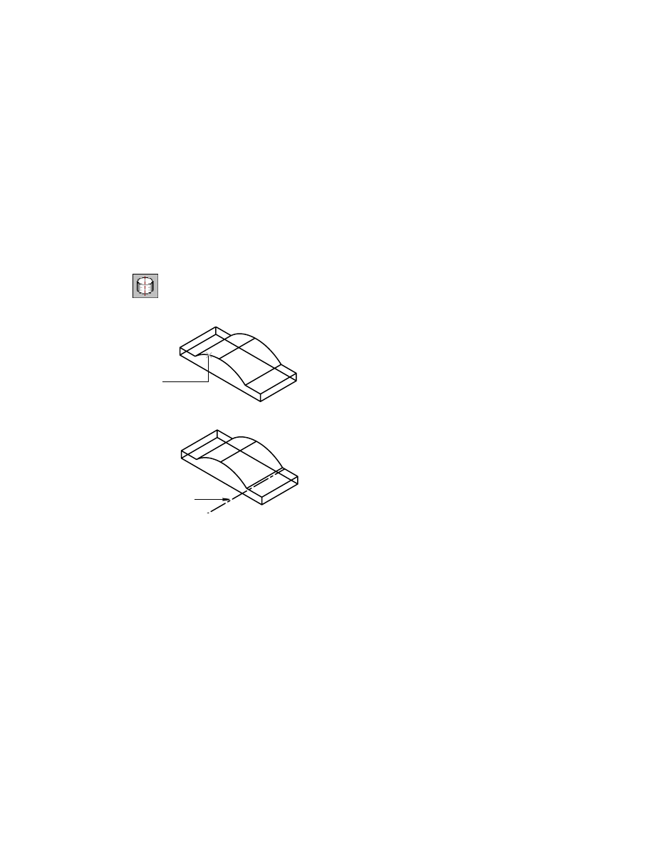
Creating Work Features
Now that you have created the base feature, add the feature that defines the
rough shape of the bracket. First, create work features to maintain symmetry.
Then, use them to draw, constrain, and extrude the sketch.
The first work feature is a work axis along the centerline of the arc on the base
feature. This work axis anchors your next sketch to the base feature.
To create a work axis
1
Use
AMWORKAXIS
to create the work axis, responding to the prompt.
Context Menu
In the graphics area, right-click and choose Sketched &
Work Features ➤ Work Axis.
Select cylinder, cone or torus [Sketch]:
Specify the cylindrical face (1)
The work axis is displayed as a line along the center of the arc.
If the work axis is not visible, the work axis display is probably turned off.
2
To turn on the display, in the Browser right-click Work Axis1. Choose Visible.
The next work feature, the work plane, forms the second axis of symmetry.
This plane is parallel to the front face and intersects both lugs. You specify
the work plane position as parallel to the selected face and offset one-half the
depth of the part.
1
work axis
Creating Base Features
|
265
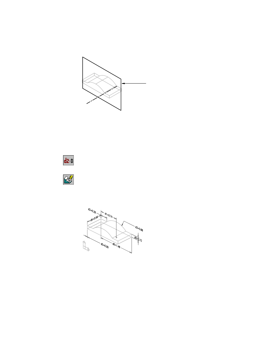
To locate the work plane parametrically, specify the offset depth as an equa-
tion. By using an equation, the work plane tracks changes in the bracket
width and always remains centered. To use an equation, you must determine
the dimension parameter before you define the work plane.
To create a work plane
1
Use
AMDIMDSP
to set dimensions as equations.
Context Menu
In the graphics area, right-click and choose Dimensioning
➤ Dimensions as Equations.
2
Redisplay the sketch dimensions, following the prompt.
Context Menu
In the graphics area, right-click and choose Edit Features
➤ Edit.
Enter an option [Sketch/surfCut/Toolbody/select Feature] <select Feature>:
Specify any point on the part
3
Choose OK to exit the Extrusion dialog box.
Parameter d6 is the dimension that specifies the width of the feature. Because
the dimension parameters for your sketch may differ, make note of the
parameter for your part.
work plane
266
|
Chapter 12
Creating Parts
4
Press
ENTER
to exit the command.
5
Create a parametric work plane in the center of the part, parallel to the front
surface, and offset one-half the width of the part.
Context Menu
In the graphics area, right-click and choose Sketched &
Work Features ➤ Work Plane.
6
In the Work Plane Feature dialog box, specify:
1st Modifier:
Planar Parallel
2nd Modifier:
Offset
Offset:
d6/2 (substitute your parameter value for d6)
Create Sketch Plane:
Clear the check box
NOTE
By default, the Create Sketch Plane option in the Work Plane Feature
dialog box is selected. This setting automatically places the sketch plane (the
location on which the next feature will be sketched or placed) on the work plane.
For this exercise, you specify a sketch plane on a surface of the feature, not on
the work plane.
Choose OK.
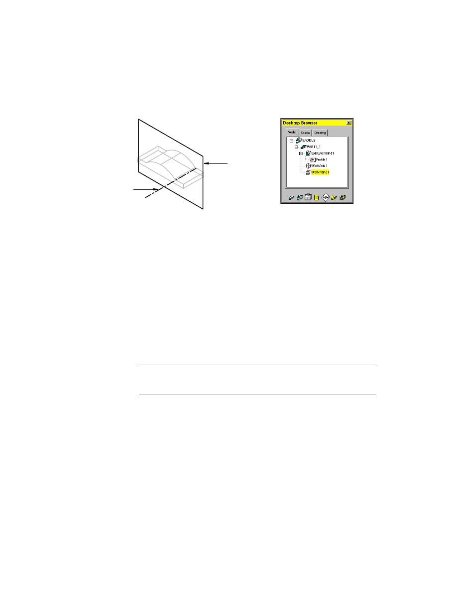
7
Identify the part face to which the work plane is parallel, responding to the
prompts.
Select work plane, planar face or [worldXy/worldYz/worldZx/Ucs]:
Select the curved edge on the front face (1)
Enter an option [Next/Accept] <Accept>:
Press
ENTER
Enter an option [Flip/Accept] <Accept>:
Enter f to flip the direction into the part
Enter an option [Flip/Accept] <Accept>:
Press
ENTER
1
Creating Base Features
|
267
The work plane is displayed as a planar rectangle. The Desktop Browser dis-
plays both a work axis and a work plane icon.
Save your file.
Defining Sketch Planes
Before you can sketch the next feature, you must define a new sketch plane,
an infinite XY plane that locates a 2D sketching surface in 3D space.
When you create sketched features, you determine the placement and orien-
tation of the sketch plane on a 2D plane. A 2D plane is
■
A flat part surface
■
The XY, YZ, or ZX axes of the World Coordinate System (WCS)
■
A previously defined work plane
■
The XY plane of the current user coordinate system (UCS)
Unlike a work feature, a sketch plane is a temporary object. Only one sketch
plane can exist at the same time.
NOTE
Except for base features, you must specify a sketch plane before you can
draw a sketch. With base features, the sketch plane is automatically placed on
the current UCS.
work plane
work axis
268
|
Chapter 12
Creating Parts
As you move your mouse over a part, Mechanical Desktop highlights the
faces that can be used to define a new sketch plane. Faces that cannot be used
are not highlighted. When you select a face, a temporary sketch plane
appears on that face.
You can choose the Z direction and orientation of the XY axes for the new
sketch plane.
After you have selected the options, the temporary sketch plane disappears
from the screen. You are ready to create the sketch geometry.
In the next exercise, the bottom face of the base feature is the sketch plane.
On this face, you sketch a profile to extrude through the part. Once placed,
the sketch and subsequent features remain attached to the base feature,
regardless of changes you make later.
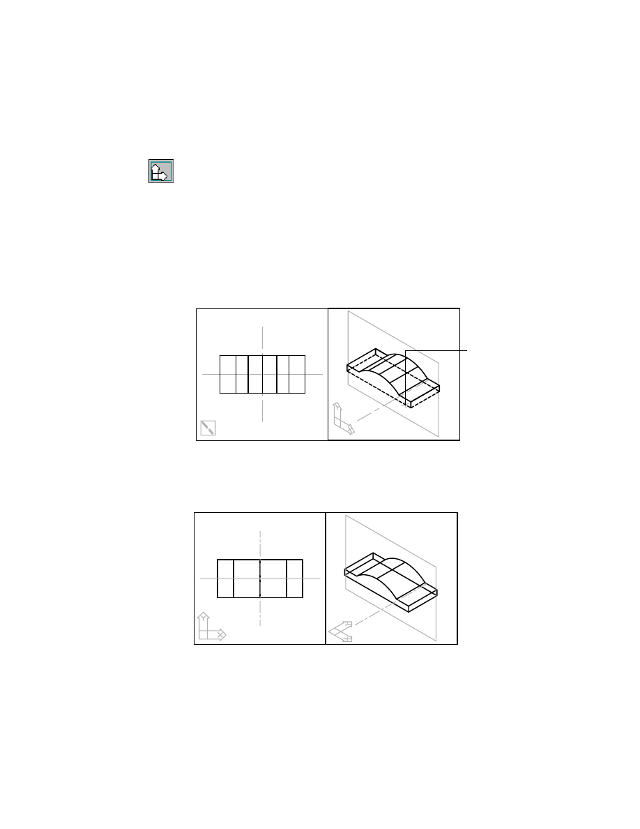
To create a sketch plane
1
Use
MCAD2
to change your display to two viewports.
Desktop Menu
View ➤ Viewports ➤ 2Viewports
The left viewport is a top view of the part; the right viewport is an isometric
view.
Before you create the sketch plane, check the system variable that controls
the UCS settings for your viewports. By default, each viewport has its own
UCS.
2
If necessary, change the UCS setting so that each viewport uses the same
UCS, responding to the prompt.
Command
UCSVP
Enter new value for UCSVP <1>:
Enter 0
temporary sketch plane
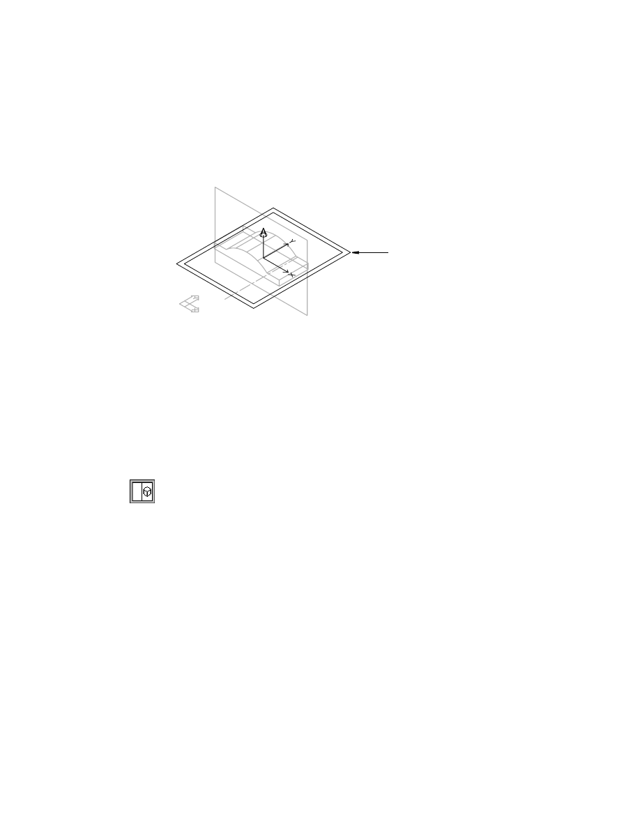
Creating Base Features
|
269
3
Use
AMSKPLN
to create a new sketch plane for the profile to be extruded,
responding to the prompts.
Context Menu
In the graphics area, right-click and choose New Sketch
Plane.
Select work plane, planar face or [worldXy/worldYz/worldZx/Ucs]:
Select the bottom face when it is highlighted (1)
Enter an option [Accept/Next] <Accept>:
Choose n to cycle to the bottom face, or press
ENTER
Select edge to align X axis or [Z-flip/Rotate]:
Enter z to flip the Z axis up through the part
Plane = Parametric
Select edge to align X axis or [Z-flip/Rotate] <accept>:
Verify that the X axis is pointing to the right, and press
ENTER
You can pick the Z axis arrow to flip the Z axis orientation. You can also pick
part and work feature edges to orient the XY plane.
The UCS icon in the viewports is updated to reflect changes in the sketch plane
orientation. The sketch plane is always coincident with the UCS XY plane.
1
270
|
Chapter 12
Creating Parts
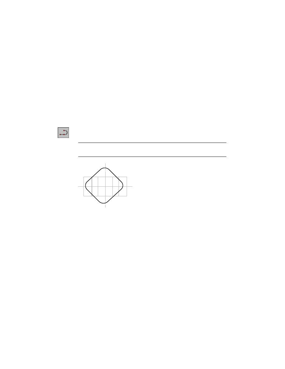
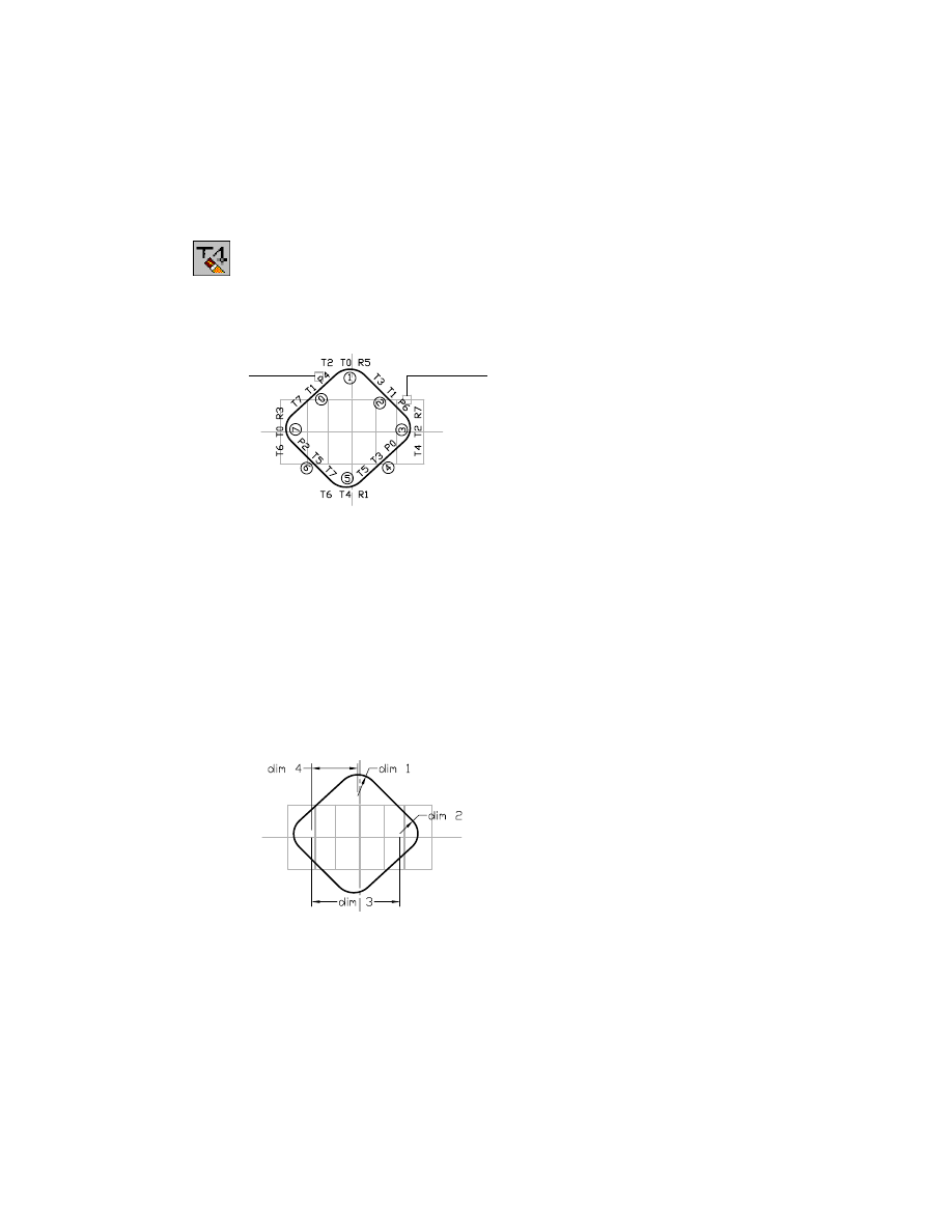
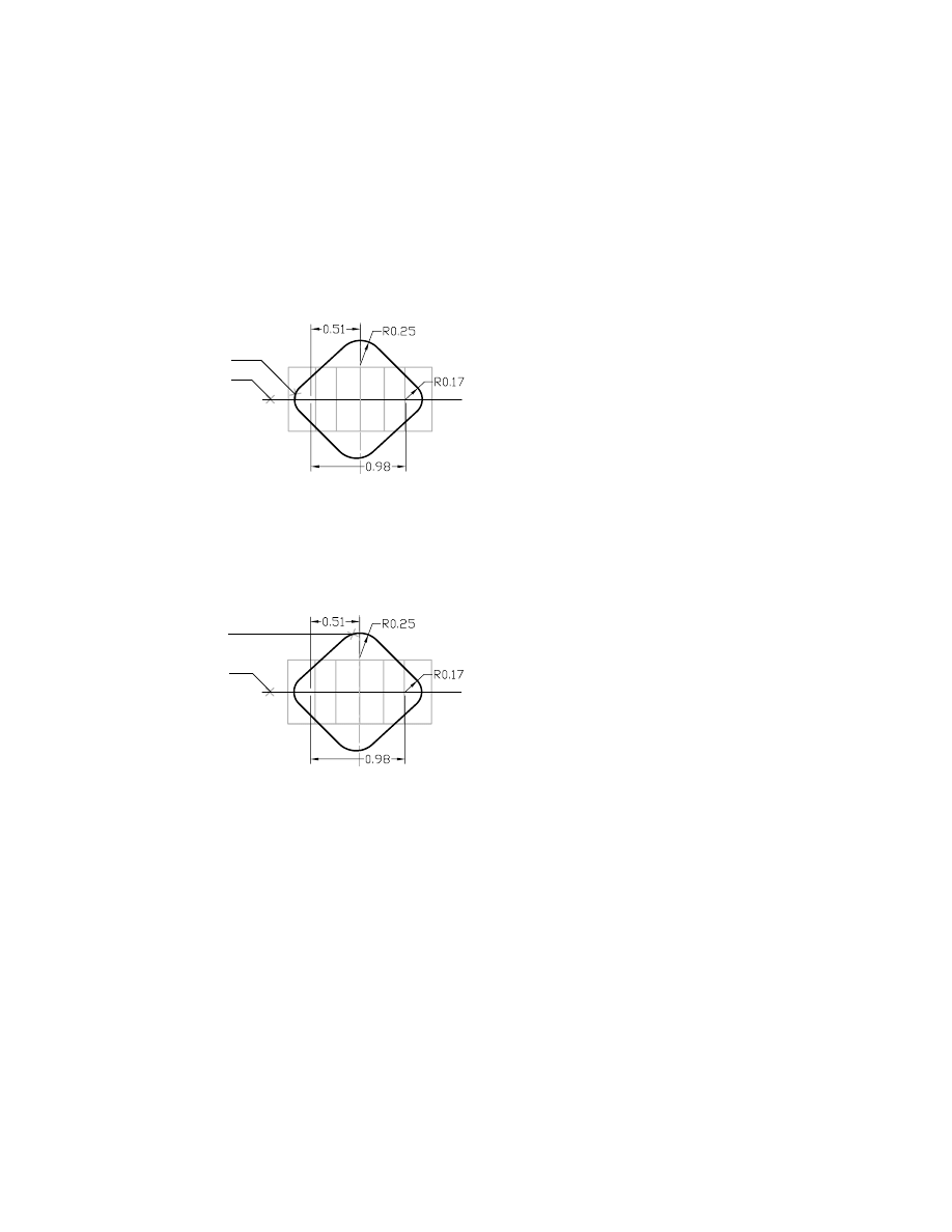
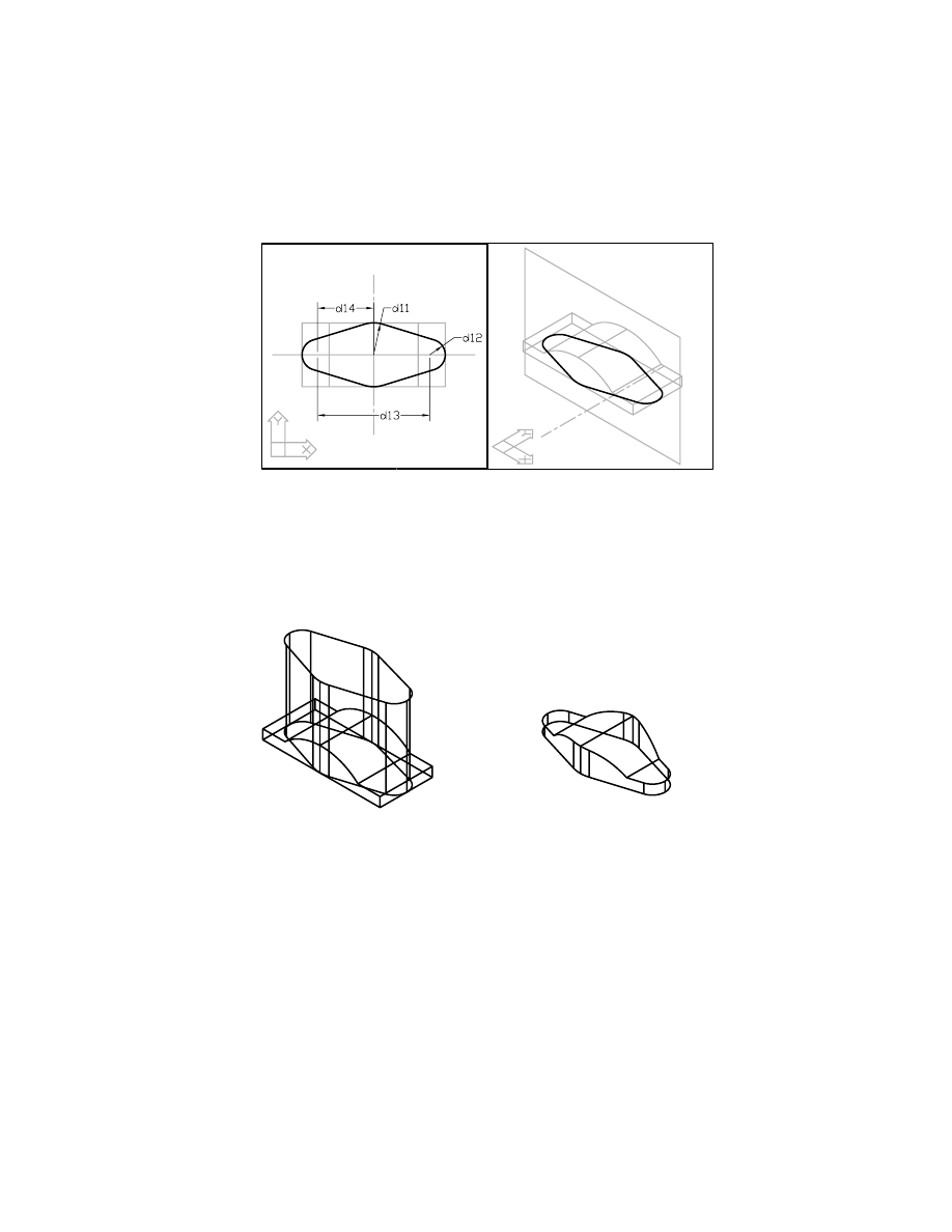
Creating Extruded Features
To define the rough shape of the saddle bracket, you sketch a diamond shape
with filleted corners and add constraints to stabilize its shape. When the fea-
ture is stabilized with geometric constraints, you add dimensions to fully
define its size. Finally, you extrude the sketch, creating a solid feature from
the combined volume of the original base feature and the extruded feature.
To create a profile sketch
1
Use
PLINE
to sketch this shape in the left viewport. With
PLINE,
you may need
to use the Direction option to control the direction of arcs.
Context Menu
In the graphics area, right-click and choose 2D Sketching
➤ Polyline.
NOTE
To make it easier to sketch the shape, make sure
POLAR
,
OSNAP
, and
OTRACK
are turned off at the bottom of your screen.
Creating Extruded Features
|
271
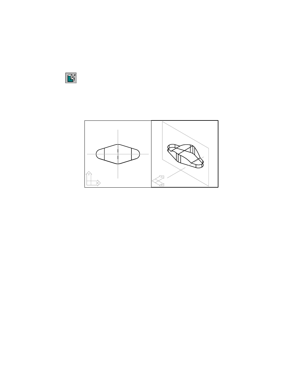
2
Use
AMPROFILE
to create a profile from the sketch.
Context Menu
In the graphics area, right-click and choose Sketch Solving
➤ Single Profile.
Mechanical Desktop analyzes the sketch, redraws it, and displays this
message:
Solved underconstrained sketch requiring 10 dimensions or constraints.
NOTE
If your sketch needs more than 10 dimensions or constraints to solve
the sketch, you probably need some tangency and constraints. Look for sharp
discontinuities between the fillets and the lines they join. You make these correc-
tions when you constrain the sketch to the base feature.
3
Look at the Desktop Browser. The profile you just created is represented as
Profile2.
Because you have not extruded the profile, it is not consumed by a feature.
Therefore, the Browser shows that Profile2 is aligned at the same level in the
hierarchy as ExtrusionBlind1.
Because you added this feature to the base feature, you need to constrain
its
shape and size and then constrain it to the existing part.
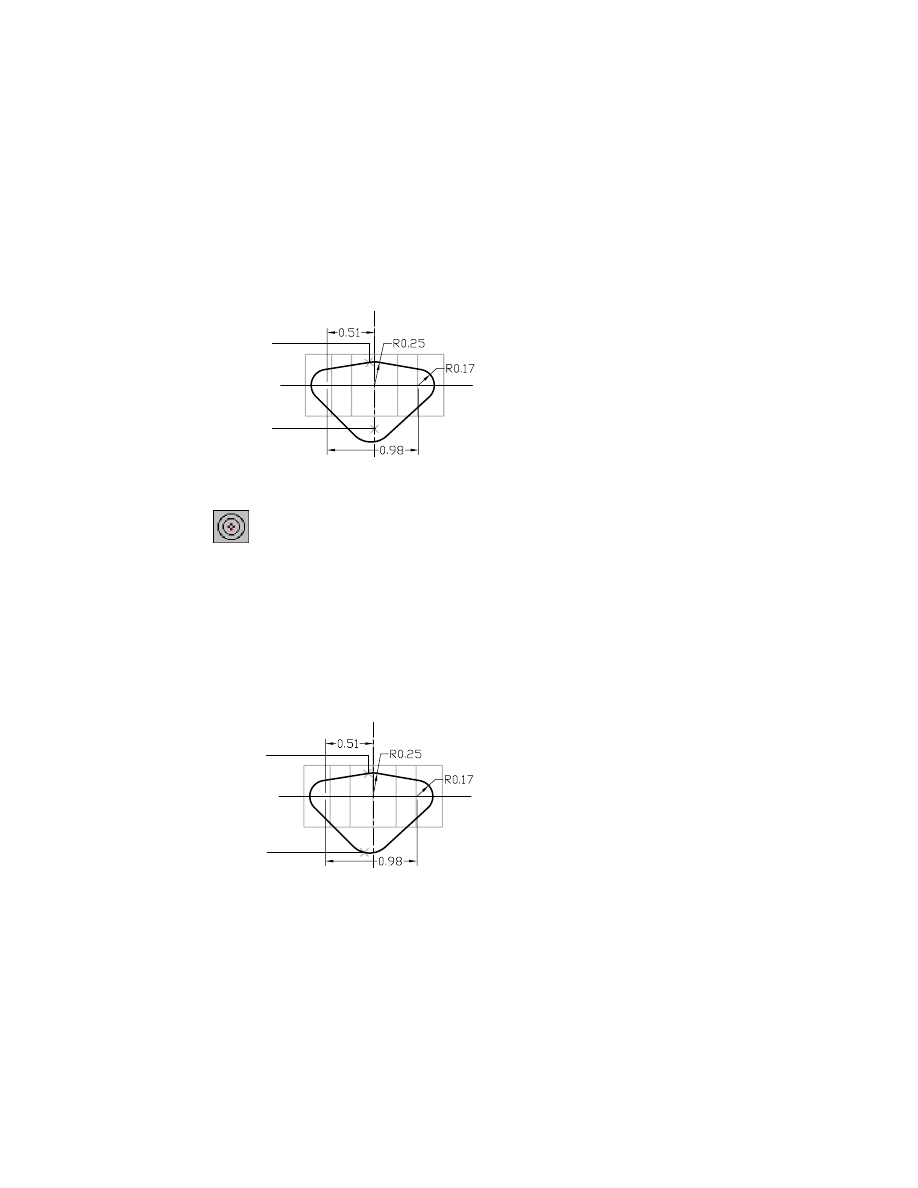
Constraining Sketches
To constrain a sketch, first you add and change geometric constraints to
create the shape of the bracket and to define its symmetry about the two
centerlines formed by the work plane and the work axis. Then you dimen-
sion the sketch to maintain the proper length and width.
NOTE
Don’t be concerned if your sketch appears to be misshapen compared
to the illustrations. Constraining the sketch to the base feature will correct its
shape.
272
|
Chapter 12
Creating Parts
To geometrically constrain a sketch
1
Use
AMADDCON
to add tangent constraints to the arcs and lines, following
the prompts.
Context Menu
In the graphics area, right-click and choose 2D
Constraints ➤ Tangent.
Valid selection(s): line, circle, arc, ellipse or spline segment
Select object to be reoriented:
Specify an arc segment
Valid selection(s): line, circle, arc, ellipse or spline segment
Select object to be made tangent to:
Specify an adjoining line segment
Solved underconstrained sketch requiring n dimensions or constraints.
Valid selection(s): line, circle, arc, ellipse or spline segment
Select object to be reoriented:
Continue adding constraints, or press
ENTER
twice to end the command
NOTE
If the constraint display is too small, choose Part ➤ Part Options and
adjust the constraint size in the Desktop Options dialog box. Redisplay the
constraints.
You need to add radial constraints so that opposing arcs have equal radii.
Radial constraints make the arcs the same size and maintain the symmetry
needed between the sides of the bracket.
Fewer dimensions are needed because one parametric dimension solves 2
degrees of freedom by specifying the size of 2 arcs.
Creating Extruded Features
|
273
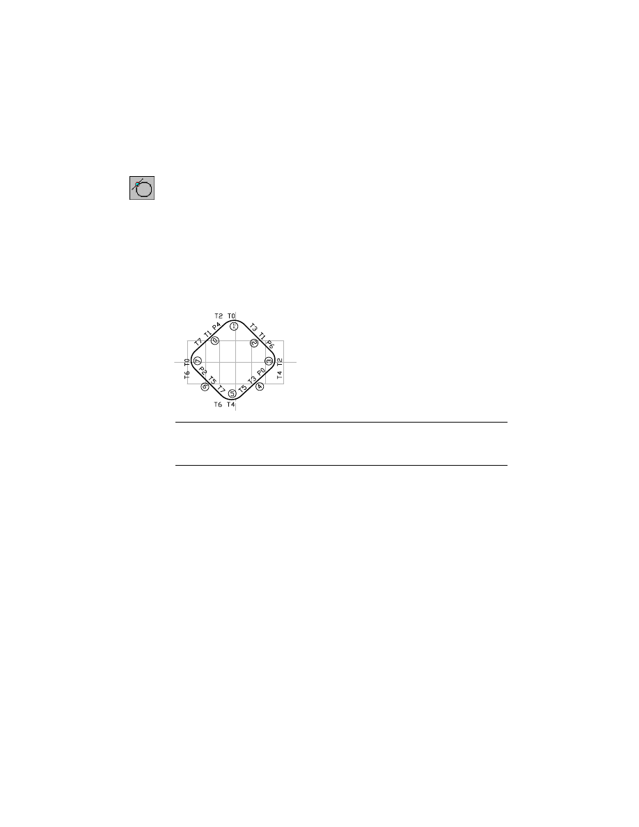
2
Select the arcs to constrain, following the prompts.
Context Menu
In the graphics area, right-click and choose 2D
Constraints ➤ Radius.
Valid selection(s): arc or circle
Select object to be resized:
Select the arc at the top of the sketch (1)
Valid selection(s): arc or circle
Select object radius is based on:
Select the arc at the bottom of the sketch (2)
Solved underconstrained sketch requiring 9 dimensions or constraints.
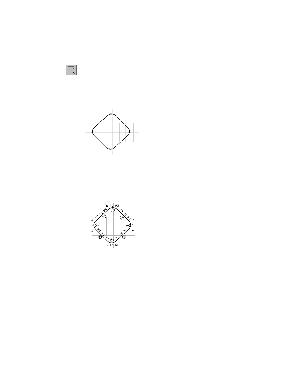
3
Add radial constraints to the left and right arcs to make them equal in size.
Valid selection(s): arc or circle
Select object to be resized:
Select the arc at the right of the sketch (3)
Valid selection(s): arc or circle
Select object radius is based on:
Select the arc at the left of the sketch (4)
Solved underconstrained sketch requiring 8 dimensions or constraints.
Your left viewport should look like this.
If you sketched in a different order, your arcs and lines may be numbered
differently.
Valid selection(s): arc or circle
Select object to be resized:
Press
ENTER
Enter an option
[Hor/Ver/PErp/PAr/Tan/CL/CN/PRoj/Join/XValue/YValue/Radius/Length/Mir/Fix/
eXit] <eXit>:
Press
ENTER
1
3
4
2
274
|
Chapter 12
Creating Parts
4
Delete any parallel constraints, responding to the prompts
If your sketch doesn’t contain parallel constraints, skip this procedure.
Context Menu
In the graphics area, right-click and choose 2D
Constraints ➤ Delete Constraints.
Select or [Size/All]:
Specify the constraint with the P symbol (1)
Select or [Size/All]:
Specify the constraint with the P symbol (2)
Select or [Size/All]:
Press
ENTER
These parallel constraints, although valid, conflict with adding dimensions
between arc centers. You need to remove the parallel constraints to prevent
overconstraining the sketch.
Save your file.
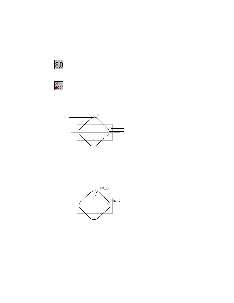
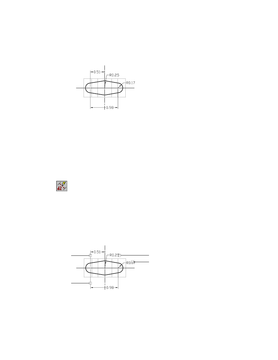
Dimensioning Sketches
Now that the feature is stabilized with geometric constraints, you can dimen-
sion the distance between the arc centers and specify the arc radius. You need
four dimensions: a radius dimension for each arc, a dimension between the
left and right arc centers, and a dimension between the center of the sketch
and the center of either the left or right arc.
1
2
Creating Extruded Features
|
275
To dimension a sketch
1
Use
AMDIMDSP
to change the dimension display back to numbers.
Context Menu
In the graphics area, right-click and choose Dimensioning
➤ Dimensions as Numbers.
2
Use
AMPARDIM
to dimension the radius for the top and right arcs, responding
to the prompts.
Context Menu
In the graphics area, right-click and choose Dimensioning
➤ New Dimension.
Select first object:
Specify the arc (1)
Select second object or place dimension:
Place the dimension (2)
Enter dimension value or [Undo/Diameter/Ordinate/Placement point]
<0.1986>:
Enter .25
3
Continue on the command line.
Select first object:
Specify the arc (3)
Select second object or place dimension:
Place the dimension (4)
Enter dimension value or [Undo/Diameter/Ordinate/Placement point]
<0.1676>:
Enter .17
Your sketch should look like this.
1
2
4
3
276
|
Chapter 12
Creating Parts
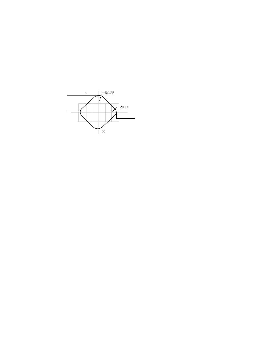
4
Create a horizontal dimension between the centers of the left and right arcs.
Select first object:
Specify the left arc center (1)
Select second object or place dimension:
Specify the right arc center (2)
Specify dimension placement:
Place the dimension (3)
Enter dimension value or [Undo/Hor/Ver/Align/Par/aNgle/Ord/Diameter/pLace]
<0.9797>:
Press
ENTER
5
Dimension the distance between the centers of the top and left arcs.
Select first object:
Specify the left arc center (1)
Select second object or place dimension:
Specify the top arc center (4)
Specify dimension placement:
Create a horizontal dimension (5)
Enter dimension value or [Undo/Hor/Ver/Align/Par/aNgle/Ord/Diameter/pLace]
<0.5135>:
Press
ENTER
6
Press
ENTER
to exit the command.
In this case, you do not change the values while you create the dimensions.
While a sketch is underconstrained, dimension changes can cause it to dis-
tort, and you may not be able to recover its correct shape.
Creating Constraints Between Features
The sketch geometry is now completely defined. However, to position the
sketch symmetrically on the base feature, you need to constrain the sketch to
the work plane and the work axis because they serve as centerlines for the part.
You use the project (PR) constraint to project points onto objects (similar to the
NEA object snap) and the concentric (C) constraint to force two arc or circle
centers to be coincident.
As you determined when you first analyzed the part,
■
The left and right arcs of the sketch form the lugs for the saddle bracket.
The arc centers must lie on the work plane.
■
The top and bottom arcs of the sketch form the base for the boss, in the
exact center of the part. The centers of both top and bottom arcs are coin-
cident with the intersection of the work plane and the work axis.
2
3
1
4
5
Creating Extruded Features
|
277
To constrain a sketch to a base feature
1
Use
AMADDCON
to make the center of the right arc lie on the work plane,
responding to the prompts.
Context Menu
In the graphics area, right-click and choose 2D
Constraints ➤ Project.
Valid selection(s): line, circle, arc, ellipse or spline segment
Specify a point to project:
Enter cen
of:
Specify the arc (1)
Valid selection(s): line, circle, arc, ellipse, work point or spline segment
Select object to be projected to:
Specify the work plane (2)
To make selecting lines and arcs easier, use transparent
ZOOM
. You can zoom
in or out while using an active command. At the Command prompt, enter
‘z, and select the area of the sketch you want to magnify. Then continue with
the active command.
NOTE
If you do not use the cen object snap to specify the arc centers, you will
not be able to create the project constraints.
rough shape
rough shape as a part
1
2
278
|
Chapter 12
Creating Parts
2
Make the center of the left arc lie on the work plane.
Valid selection(s): line, circle, arc, ellipse or spline segment
Specify a point to project:
Enter cen
of:
Specify the arc (1)
Valid selection(s): line, circle, arc, ellipse, work point or spline segment
Select object to be projected to:
Specify the work plane (2)
3
Position the center of the top arc on the work plane.
Valid selection(s): line, circle, arc, ellipse or spline segment
Specify a point to project:
Enter cen
of:
Specify the arc (1)
Valid selection(s): line, circle, arc, ellipse, work point or spline segment
Select object to be projected to:
Specify the work plane (2)
2
1
1
2
Creating Extruded Features
|
279
4
Position the center of the top arc on the work axis.
Valid selection(s): line, circle, arc, ellipse or spline segment
Specify a point to project:
Enter cen
of:
Specify the arc (1)
Valid selection(s): line, circle, arc, ellipse, work point or spline segment
Select object to be projected to:
Specify the work axis (2)
5
Use AMADDCON to make the center of the bottom arc concentric with the
center of the top arc, responding to the prompts.
Context Menu
In the graphics area, right-click and choose 2D
Constraints ➤ Concentric.
Valid selection(s): arc, circle, or ellipse
Select object to be reoriented:
Specify the bottom arc (1)
Valid selection(s): arc, circle, ellipse, or work point
Select object to be made concentric to:
Specify the top arc (2)
Valid selection(s): arc, circle, or ellipse
Select object to be reoriented:
Press
ENTER
Enter an option
[Hor/Ver/PErp/PAr/Tan/CL/CN/PRoj/Join/XValue/YValue/Radius/Length/Mir/Fix/
eXit] <eXit>:
Press
ENTER
1
2
1
2
280
|
Chapter 12
Creating Parts
Your sketch should be fully solved and look like this.
Save your file.
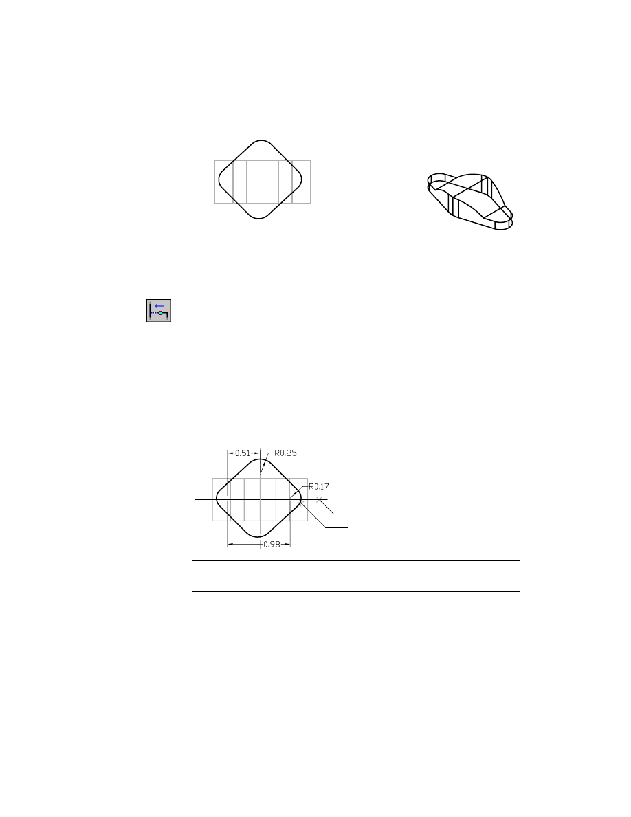
Editing Sketches
Now that the sketch is fully constrained, you can change the sketch dimen-
sions to position the sketch on your part. Modify the distances between the
center of the left arc and the center of the sketch and between the centers of
the left and right arcs.
To change a sketch dimension
1
Use
AMMODDIM
to modify the values of the dimensions, following the
prompts.
Context Menu
In the graphics area, right-click and choose Dimensioning
➤ Edit Dimension.
Select dimension to change:
Specify the dimension (1)
New value for dimension: <0.25>:
Enter .33
Select dimension to change:
Specify the dimension (2)
New value for dimension: <0.17>:
Enter .16
Select dimension to change:
Specify the dimension (3)
New value for dimension: <0.98>:
Enter 1.16
Select dimension to change:
Specify the dimension (4)
New value for dimension: <0.51>:
Enter .56
Select dimension to change:
Press
ENTER
2
1
4
3
Creating Extruded Features
|
281
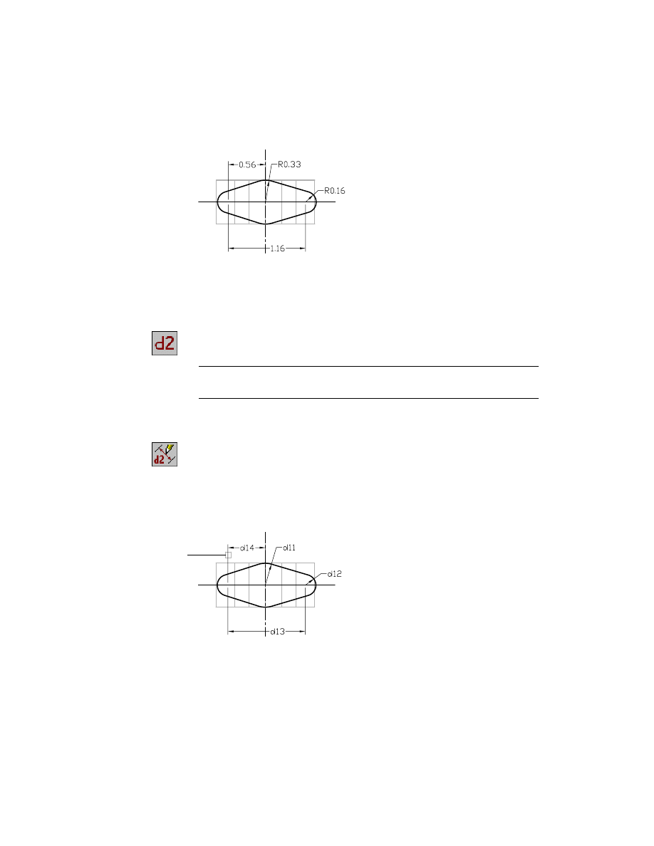
Your part should look like this.
Now, you need to create an equation between the overall dimension and the
dimension that centers the feature on the part and maintains symmetry
relative to the work axis. Display the dimensions as parameters, and then use
them as variables in the parametric equation.
2
Use
AMDIMDSP
to display the dimensions as parameters.
Context Menu
In the graphics area, right-click and choose Dimensioning
➤ Dimensions As Parameters.
NOTE
Your dimension parameter numbers may differ from those shown in the
illustration.
3
Make the dimension between the top and left arcs one-half the horizontal
distance between the left and right arcs, following the prompts.
Context Menu
In the graphics area, right-click and choose Dimensioning
➤ Edit Dimension.
Select dimension to change:
Specify the dimension (1)
Enter new value for dimension <.56>:
Enter =dx/2, where x is the dimension that corresponds to d13 in the illustration
Select dimension to change:
Press
ENTER
1
282
|
Chapter 12
Creating Parts
Now that the profile sketch is completely constrained and dimensioned, you
can use it to change the shape of the base feature.
Extruding Profiles
You create a solid feature by extruding the profile through to the boundary
of the base feature, retaining the common volume. To create the rough shape
of the saddle bracket, you extrude the profile sketch up and completely
through the base feature. Because the sketch you extrude changes the shape
of the base feature, the intersection shares the volume of both.
base features
resulting intersection
Creating Extruded Features
|
283
To extrude a profile through a base feature
1
Use
AMEXTRUDE
to create the extrusion.
Context Menu
In the graphics area, right-click and choose Sketched &
Work Features ➤ Extrude.
In the Extrusion dialog box, accept the default size and specify:
Operation:
Intersect
Flip:
Verify that the direction arrow is pointed up through the part
Termination:
Through
Choose OK to exit the dialog box and create the extrusion.
Save your file.
284
|
Chapter 12
Creating Parts
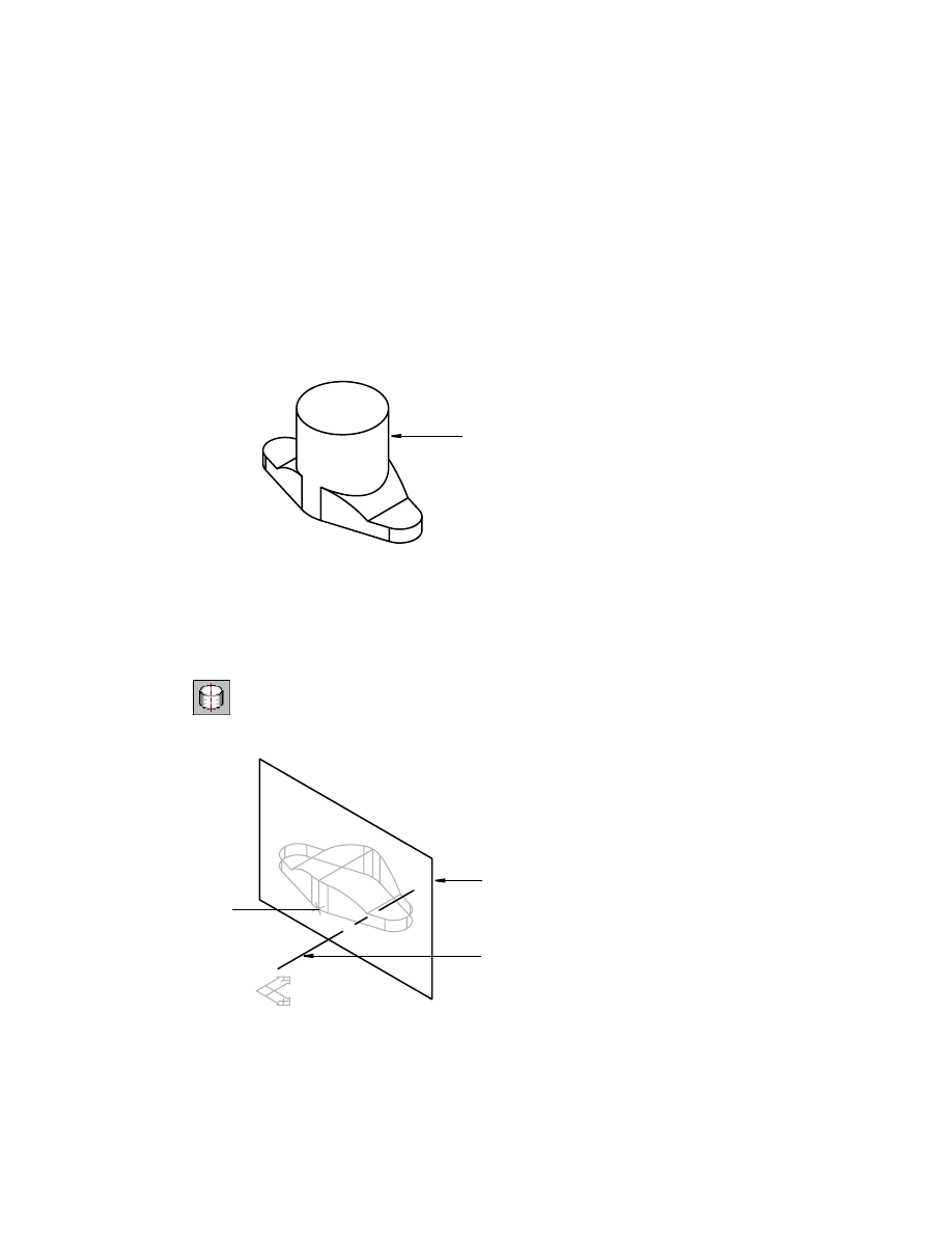
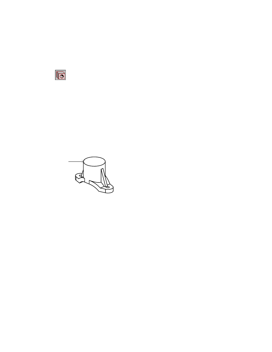
Creating Revolved Features
With the rough shape of the saddle bracket defined, you can create the next
dependent feature, the boss, which is a cylinder. The fastest and most effi-
cient method to model the cylindrical boss is to extrude a circle. Alterna-
tively, you can revolve a rectangle about a central axis. This method is used
here to teach you the revolving method.
When you finish the exercise, your model will look like this.
Before you can sketch the profile for the revolved feature, you need to create
a work axis to serve as the centerline for the revolved feature. Work in the
right viewport, the isometric view.
To sketch a profile for a revolved feature
1
Use AMWORKAXIS to create a work axis, responding to the prompt.
Context Menu
In the graphics area, right-click and choose Sketched &
Work Features ➤ Work Axis.
Select cylinder, cone or torus [Sketch]:
Specify the face (1)
boss
1
work plane
work axis
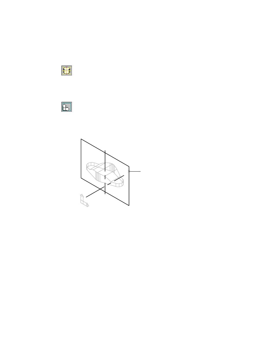
Creating Revolved Features
|
285
2
A work axis passes vertically through the part. If the work axis is not dis-
played, use
AMVISIBLE
to display it.
Desktop Menu
Part ➤ Part Visibility
In the Desktop Visibility dialog box, choose the Part tab and check Work
Axes. Select Unhide and choose OK.
Next, you need to create a new sketch plane. Because the cylinder is vertical,
you place the sketch plane on the previously defined work plane.
3
Create a new sketch plane, responding to the prompts.
Context Menu
In the graphics area, right-click and choose New Sketch
Plane.
Select work plane, planar face or [worldXy/worldYz/worldZx/Ucs]:
Specify the work plane (1)
Plane = Parametric
Select edge to align X axis or [Flip/Rotate/Origin] <Accept>:
Press
ENTER
The sketch plane assumes the Z direction and XY orientation of the work
plane.
4
Hide the work plane. This time use the Browser method.
Browser
Right-click WorkPlane1 and choose Visible
The work plane is no longer visible.
1
286
|
Chapter 12
Creating Parts
5
Make the left viewport active and change the view
so that you see a front
view of the part as you look at the sketch plane.
Desktop Menu
View ➤ 3D Views ➤ Front
6
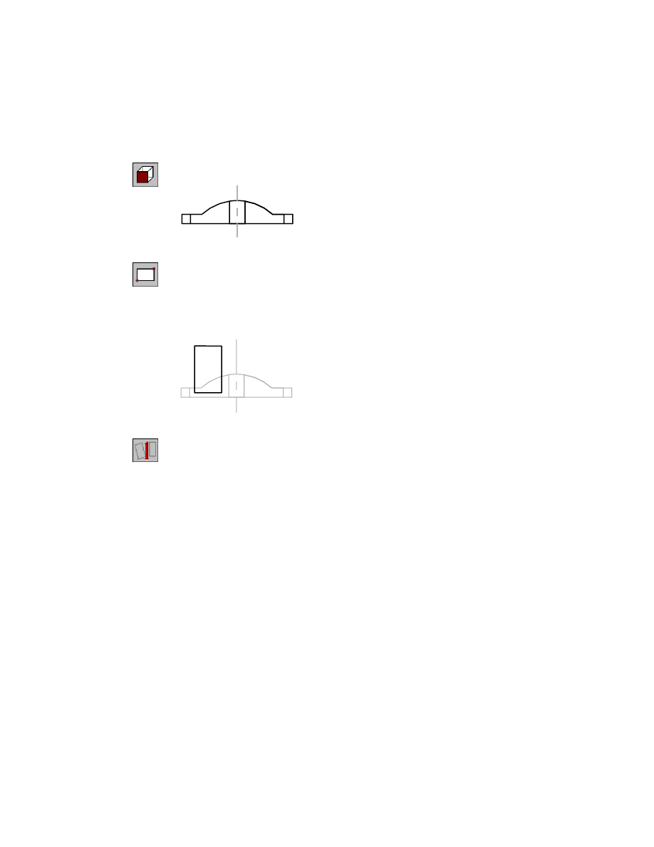
Sketch a rectangular outline of the cylinder, following the prompts.
Context Menu
In the graphics area, right-click and choose 2D Sketching
➤ Rectangle.
Specify first corner point or [Chamfer/Elevation/Fillet/Thickness/Width]:
Specify a point
Specify other corner point:
Specify a second point
7
Use AMPROFILE to convert the sketch to a profile for the feature.
Context Menu
In the graphics area, right-click and choose Sketch Solving
➤ Single Profile.
Mechanical Desktop selects the sketch you just drew, and converts it to a pro-
file. The sketch still needs four dimensions or constraints.
Creating Revolved Features
|
287
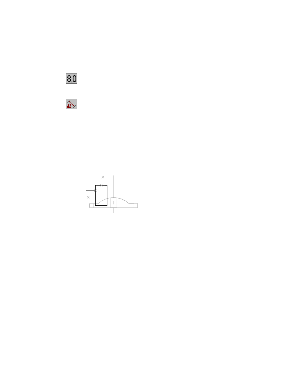
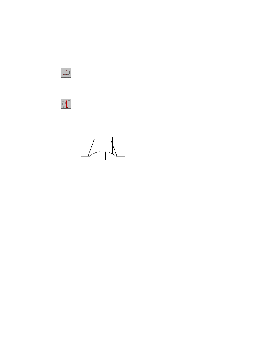
To constrain a profile sketch to revolve
1
Use
AMDIMDSP
to change the dimension display to numbers.
Context Menu
In the graphics area, right-click and choose Dimensioning
➤ Dimensions as Numbers.
2
Use
AMPARDIM
to dimension the length and width of the sketch, following
the prompts.
Context Menu
In the graphics area, right-click and choose Dimensioning
➤ New Dimension.
Select first object:
Specify the line (1)
Select second object or place dimension:
Place the dimension (2)
Enter dimension value or [Undo/Hor/Ver/Align/Par/aNgle/Ord/Diameter/pLace]
<0.3629>:
Enter .33
Solved underconstrained sketch requiring 3 dimensions or constraints.
Select first object:
Specify the line (3)
Select second object or place dimension:
Place the dimension (4)
Enter dimension value or [Undo/Hor/Ver/Align/Par/aNgle/Ord/Diameter/pLace]
<0.6687>:
Enter .78
Solved underconstrained sketch requiring 2 dimensions or constraints.
Select first object:
Press
ENTER
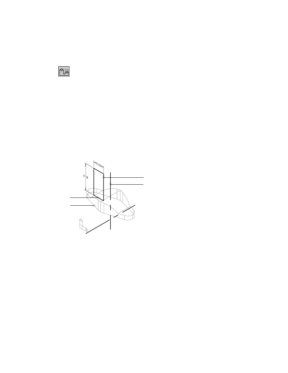
In the right viewport, constrain the sketch to the part as follows:
■
Make the bottom line of the sketch collinear with the bottom of the part.
■
Make the right side of the rectangle collinear with the vertical work axis
so that it serves as the axis of revolution of the feature.
1
3
2
4
288
|
Chapter 12
Creating Parts
3
Use
AMADDCON
to add collinear constraints, following the prompts.
Context Menu
In the graphics area, right-click and choose 2D
Constraints ➤ Collinear.
Valid selections: line or spline segment
Select object to be reoriented:
Specify the line (1)
Valid selections: line or spline segment
Select object to be made collinear to:
Specify the vertical work axis (2)
Solved underconstrained sketch requiring 1 dimensions or constraints.
Valid selections: line or spline segment
Select object to be reoriented:
Specify the line (3)
Valid selections: line or spline segment
Select object to be made clinger to:
Specify the part edge (4)
Solved fully constrained sketch.
Valid selections: line or spline segment
Select object to be reoriented:
Press
ENTER
Enter an option [Hor/Ver/PErp/PAr/Tan/CL/CN/PRoj/Join/XValue/YValue/Radius/
Length/Mir/Fix/eXit] <eXit>:
Press
ENTER
In the next procedure, you create the cylinder by revolving the sketch about
the work axis. You can also revolve a sketch about a part edge or about a line
in the profile sketch.
3
4
1
2
Creating Revolved Features
|
289
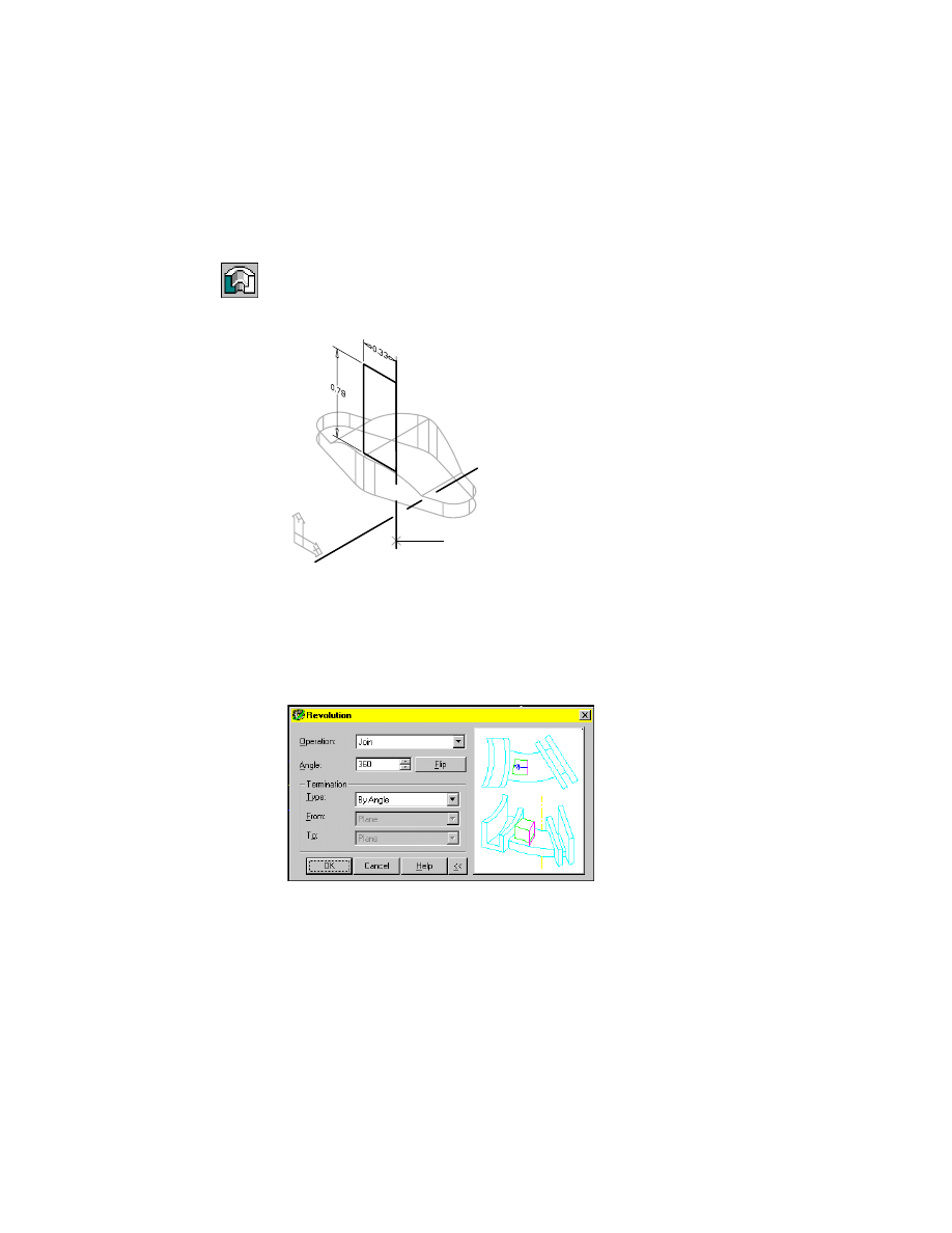
To revolve a feature about a work axis
1
Use
AMREVOLVE
to revolve the sketch about the work axis, responding to the
prompt.
Context Menu
In the graphics area, right-click and choose Sketched &
Work Features ➤ Revolve.
Select revolution axis:
Specify the axis (1)
2
In the Revolution dialog box, specify the operation, termination, and angle
of revolution. Because the cylinder attaches to the part, define the revolution
to be a full (360 degrees) termination that joins to the part.
Operation:
Join
Angle:
Enter 360
Termination:
By Angle
Choose OK.
1
290
|
Chapter 12
Creating Parts
After specifying the type of revolution and the axis of rotation, the cylinder
is created on your model.
Save your file.
Creating Symmetrical Features
The final features are the strengthening ribs, located on each side of the saddle
just above the lugs.
The ribs can be created simultaneously from a single open profile sketch. You
sketch an outline of the ribs, and add dimensions and constraints to make
the ribs symmetrical. Then you extrude the ribs automatically with the Rib
feature.
The sketch you create lies on the same plane as the revolution feature, so it
is not necessary to create a new sketch plane.
Before you begin, change to the front view, and one viewport.
strengthening rib
Creating Symmetrical Features
|
291
To sketch a feature on a part
1
Use
PLINE
to sketch the ribs.
Context Menu
In the graphics area, right-click and choose 2D Sketching
➤ Polyline.
Sketch a three-segment polyline in the approximate outline of the ribs. The
lines don’t have to touch the saddle.
2
Use
AMPROFILE
to create an open profile from the sketch.
Context Menu
In the graphics area, right-click and choose Sketch Solving
➤ Single Profile.
Respond to the prompt.
Select part edge to close the profile <open profile>:
Press
ENTER
Next, constrain the sketch.
Constraining Sketches
When you solved the sketch, a parallel constraint was applied between the
top horizontal line of the part and the horizontal segment of the sketch. Six
additional dimension or constraints are needed to fully constrain the sketch.
Use dimensions to adjust the size of the ribs and to center them on the part.
292
|
Chapter 12
Creating Parts
To constrain a sketch
1
Use
AMPARDIM
to dimension the distance between the top of the sketch and
the top of the part.
Context Menu
In the graphics area, right-click and choose Dimensioning
➤ New Dimension.
Respond to the prompts as follows:
Select first object:
Specify the line (1)
Select second object or place dimension:
Specify the line (2)
Specify dimension placement:
Place the vertical dimension (3)
Enter dimension value or [Undo/Hor/Ver/Align/Par/aNgle/Ord/Diameter/pLace]
<0.1683>:
Enter .08
Solved under constrained sketch requiring 6 dimensions or constraints.
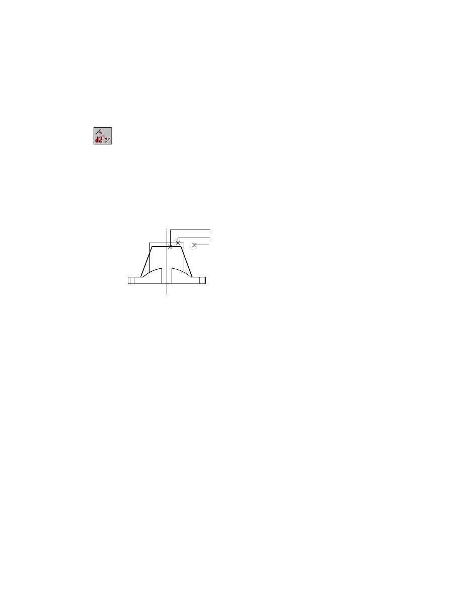
2
Add dimensions for the angle between the two ribs, and the angle between
the work axis and one rib.
Select first object:
Specify the line (1)
Select second object or place dimension:
Specify the line (2)
Enter dimension value or [Undo/Hor/Ver/Align/Par/aNgle/Ord/Diameter/pLace]
<0.1683>:
Enter n
Specify dimension placement:
Place the dimension (3)
Enter dimension value or [Undo/Placement point] <47>:
Enter 40
Select first object:
Specify the vertical work axis (4)
Select second object or place dimension:
Specify the line (1)
Specify dimension placement:
Place the angular dimension (5)
Enter dimension value or [Undo/Placement point] <20>:
Press
ENTER
2
1
3
Creating Symmetrical Features
|
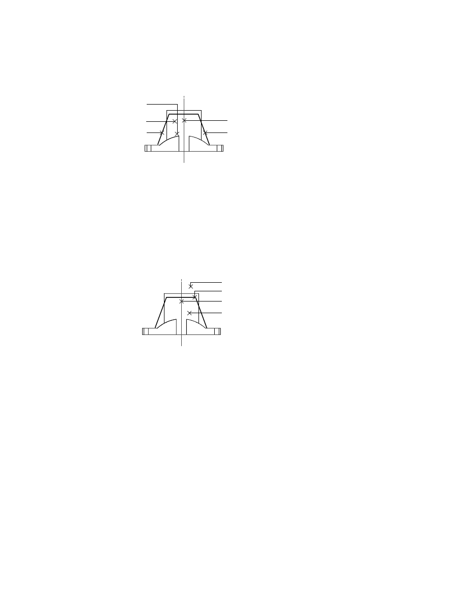
293
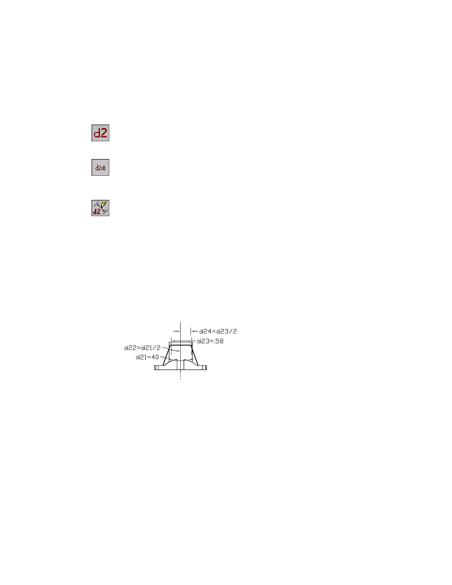
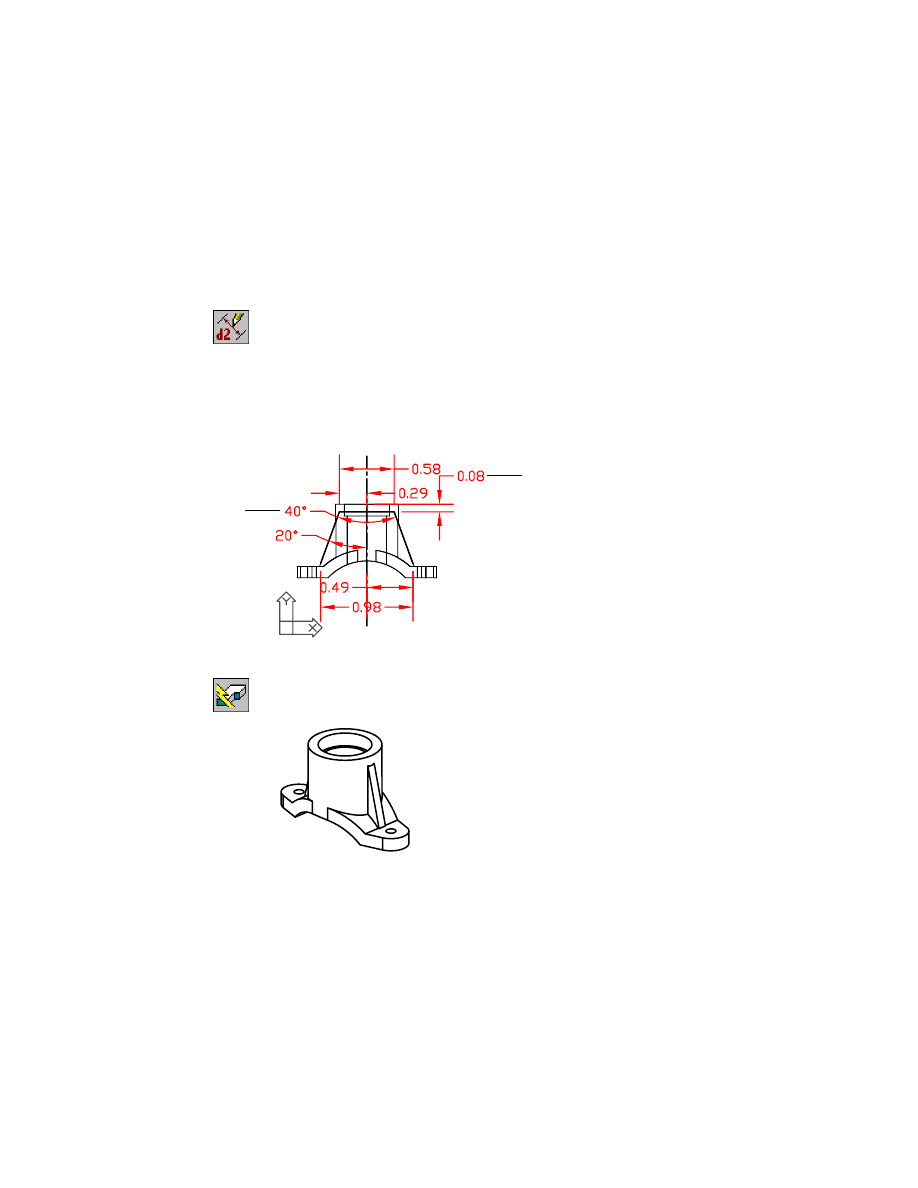
3
Add horizontal dimensions for the top line of the sketch, and from the work
axis to the outer edge of the top line.
Select first object:
Specify the line (1)
Select second object or place dimension:
Place the horizontal dimension (2)
Enter dimension value or [Undo/Hor/Ver/Align/Par/aNgle/Ord/Diameter/pLace]
<0.9806>:
Enter .58
Select first object:
Specify the outer end of line (1)
Select second object or place dimension:
Specify the work axis(3)
Specify dimension placement:
Place the horizontal dimension (4)
Enter dimension value or [Undo/Hor/Ver/Align/Par/aNgle/Ord/Diameter/pLace]
<0.9806>:
Enter .29
4
Repeat step three to add a horizontal dimension of .98 between the two lower
endpoints of the sketch, and .49 between the work axis and one lower end-
point of the sketch.
Solved fully constrained sketch.
To verify that the ribs are symmetrical, express the dimensions as equations.
Set the distance and the angle between the axis and the rib to one-half the
distance and angle between both ribs.
4
2
3
5
1
2
1
3
4
294
|
Chapter 12
Creating Parts
To display the dimensions as parameters
1
Use
AMDIMDSP
to change the display of the dimensions from numeric to
parametric.
Context Menu
In the graphics area, right-click and choose Dimensioning
➤ Dimensions As Parameters.
Display the dimensions as equations.
Context Menu
In the graphics area, right-click and choose Dimensioning
➤ Dimensions As Equations.
2
Use AMMODDIM to edit the dimensions. Use the work axis as the centerline
of the part.
Context Menu
In the graphics area, right-click and choose Dimensioning
➤ Edit Dimension.
Select dimension to change:
Specify the horizontal dimension from the work axis
to either endpoint of the top line of the sketch
New value for dimension <current>:
Enter dx/2, where x is the horizontal dimension for the top line of the sketch
Solved fully constrained sketch.
Select dimension to change:
Specify the dimension for the angle between the work axis and a side of the sketch
New value for dimension <current>:
Enter dy/2, where y is the dimension for the angle between the sides of the sketch
Solved fully constrained sketch.
Select dimension to change:
Press
ENTER
Creating Symmetrical Features
|
295
3
Use
AMUPDATE
to apply any changes to the rib sketch.
Context Menu
Right-click the graphics area and choose Update Part.
You are ready to extrude the sketch to form symmetrical ribs.
4
Use 3DOrbit to adjust the view so you can see the rib feature preview before
you create the ribs.
Desktop Menu
Choose View ➤ 3D Orbit. Rotate the view slightly to the
left, and tilt it slightly downward.
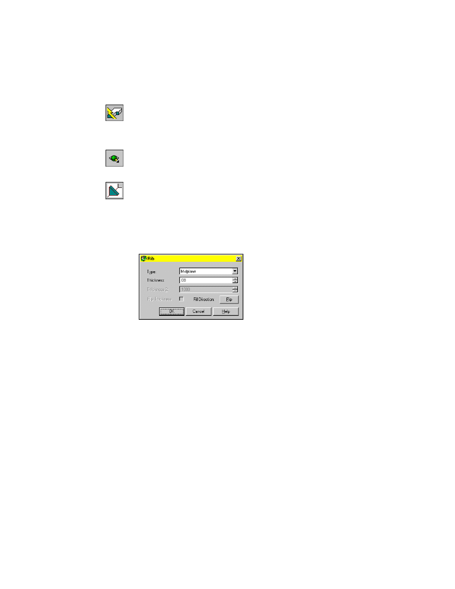
5
Use AMRIB to extrude the ribs.
Browser
In the Browser, right-click the open profile icon, and
choose Rib.
In the Rib dialog box, specify:
Type:
Midplane
Thickness:
Enter .08
Verify the direction arrow points into the part, and choose OK.
The two symmetrical ribs are extruded to the face of the cylinder.
Next, suppress the hidden lines so that you can see your model more clearly.
296
|
Chapter 12
Creating Parts
To suppress silhouette edges from Mechanical Desktop parts
1
Set the
DISPSILH
system variable to 1, responding to the prompts.
Command
DISPSILH
Enter new value for DISPSILH <0>:
Enter 1
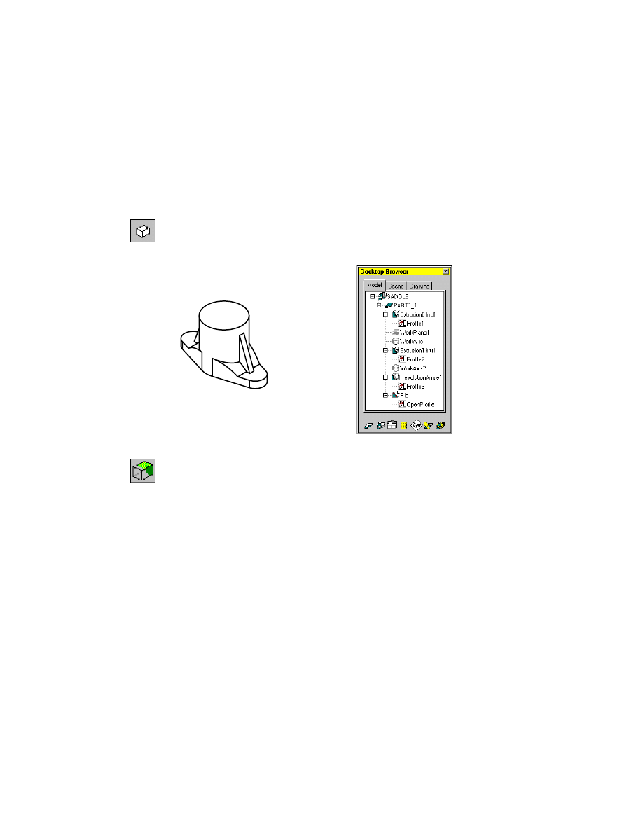
2
Use HIDE to remove the hidden lines from your display.
Desktop Menu
View ➤ Hide
Your part should now look like this. The Desktop Browser shows the hierar-
chy of the part features.
3
Return to wireframe display.
Desktop Menu
View ➤ Shade ➤ 3D Wireframe
Save your file.
Refining Parts
|
297
Refining Parts
Now, you complete the part by modifying its features in the same order as
you created them: the saddle and lugs, the boss, and the ribs.
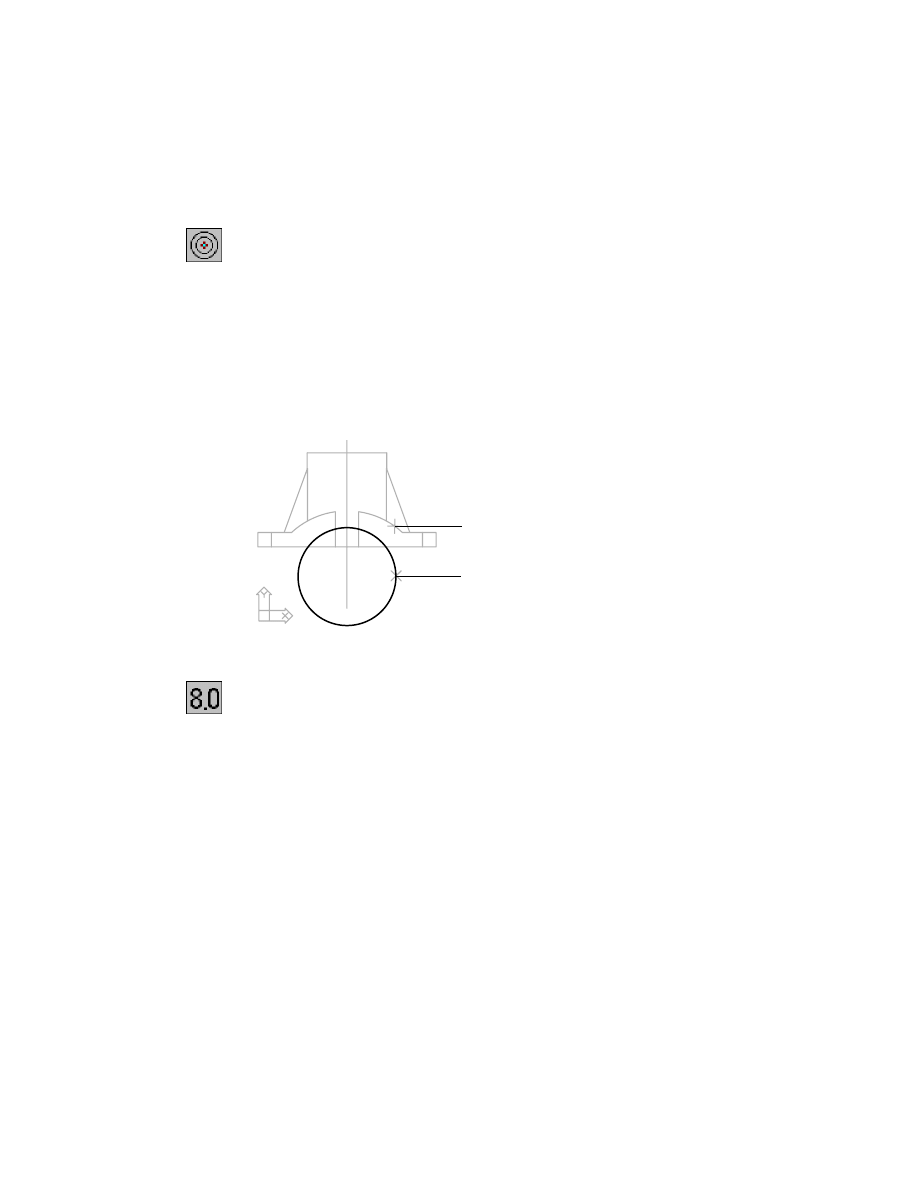
To finish the body of the saddle bracket, you need to cut the pipe saddle,
adjust the length of the lugs, and create mounting holes. To create the saddle,
you cut an arc through the front of the saddle body. To cut the arc, you create
a circle and extrude it through the part, along the horizontal work axis. For
this feature, you use the previously defined sketch plane.
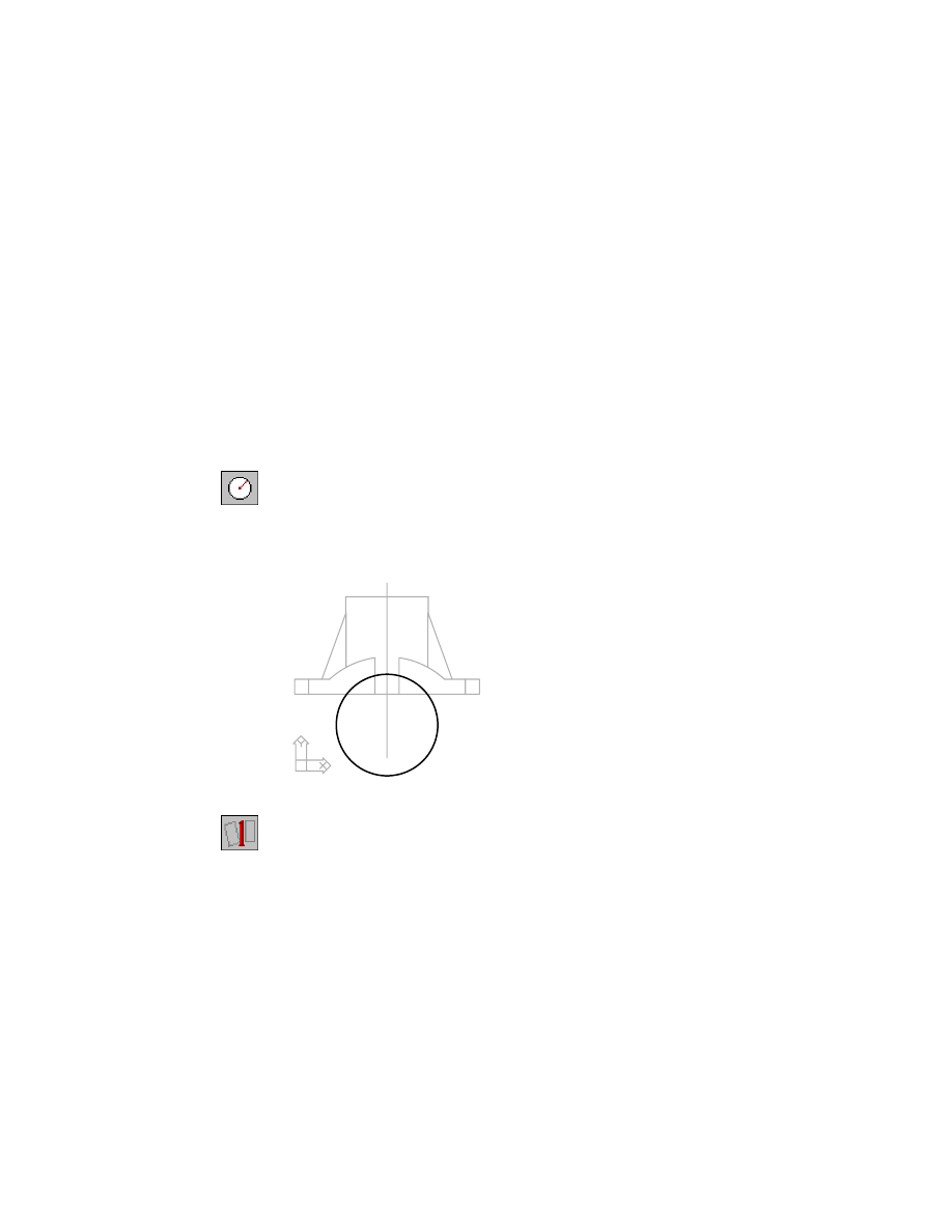
To sketch and constrain the circle to be extruded
1
Use
CIRCLE
to draw the circle to extrude, following the prompts. Work in the
left viewport.
Context Menu
In the graphics area, right-click and choose 2D Sketching
➤ Circle.
Specify center point for circle or [3P/2P/Ttr (tan tan radius)]:
Specify a center point
Specify radius of circle or [Diameter]:
Specify a point to define the radius
2
Use
AMPROFILE
to solve the sketch to convert it to a profile sketch.
Context Menu
In the graphics area, right-click and choose Sketch Solving
➤ Single Profile.
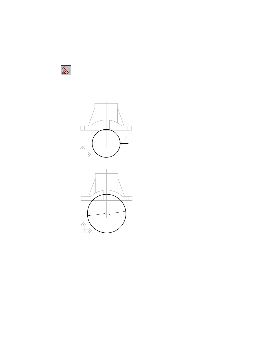
You need to constrain the circle to the part. The sketch also needs two more
dimensions: the location of the center and the diameter of the circle.
The work axis is the center of the saddle arcs on the front and back of the
bracket. By making the circle concentric with the arcs, you satisfy two con-
straints, the location of the center and the relationship of the circle to the part.
298
|
Chapter 12
Creating Parts
3
Use
AMADDCON
to constrain the circle to be concentric with the saddle arcs,
responding to the prompts.
Context Menu
In the graphics area, right-click and choose 2D
Constraints ➤ Concentric.
Valid selection(s): arc, circle, or ellipse
Select object to be reoriented:
Specify the circle (1)
Valid selection(s): arc, circle, ellipse, or work point
Select object to be made concentric to:
Specify the arc (2)
Valid selection(s): arc, circle, or ellipse
Select object to be reoriented:
Press
ENTER
Enter an option
[Hor/Ver/PErp/PAr/Tan/CL/CN/PRoj/Join/XValue/YValue/Radius/Length/Mir/Fix/
eXit] <eXit>:
Press
ENTER
4
Use
AMDIMDSP
to return the dimension display to numeric, responding to
the prompt.
Context Menu
In the graphics area, right-click and choose Dimensioning
➤ Dimensions As Numbers.
1
2
Refining Parts
|
299
5
Use
AMPARDIM
to dimension the diameter of the circle, following the
prompts.
Context Menu
In the graphics area, right-click and choose Dimensioning
➤ New Dimension.
Select first object:
Specify the circle (1)
Select second object or place dimension:
Place the dimension (2)
Enter dimension value or [Undo/Placement point] <1.0976>:
Enter 1.12
Select first object:
Press
ENTER
The sketch is now fully constrained and looks like this.
1
2
300
|
Chapter 12
Creating Parts
To extrude a feature
1
Extrude the feature, specifying a cut operation with a midplane termination.
Context Menu
In the graphics area, right-click and choose Sketched &
Work Features ➤ Extrude.
2
In the Extrusion dialog box, specify:
Operation:
Cut
Distance:
Enter .66
Termination: Type:
Mid Plane
Choose OK. The arc shape cuts through the saddle bracket.
To complete the body of the bracket, you need a placed feature on each of
the lugs for mounting holes.
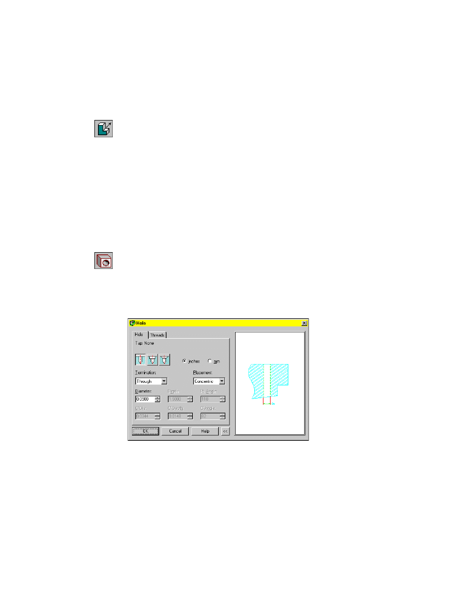
To create a drilled hole
1
Use
AMHOLE
to place the mounting holes. Work in the isometric view.
Context Menu
In the graphics area, right-click and choose Placed
Features ➤ Hole.
2
In the Hole dialog box, select the Drilled hole type icon and specify:
Termination:
Through
Placement:
Concentric
Diameter:
Enter .09
Choose OK.
Refining Parts
|
301
3
Respond to the prompts as follows:
Select work plane, planar face or [worldXy/worldYz/worldZx/Ucs]:
Specify face (1)
Enter an option [Next/Accept]<Accept>:
Press
ENTER
Select the concentric edge:
Specify edges (1) for the first hole
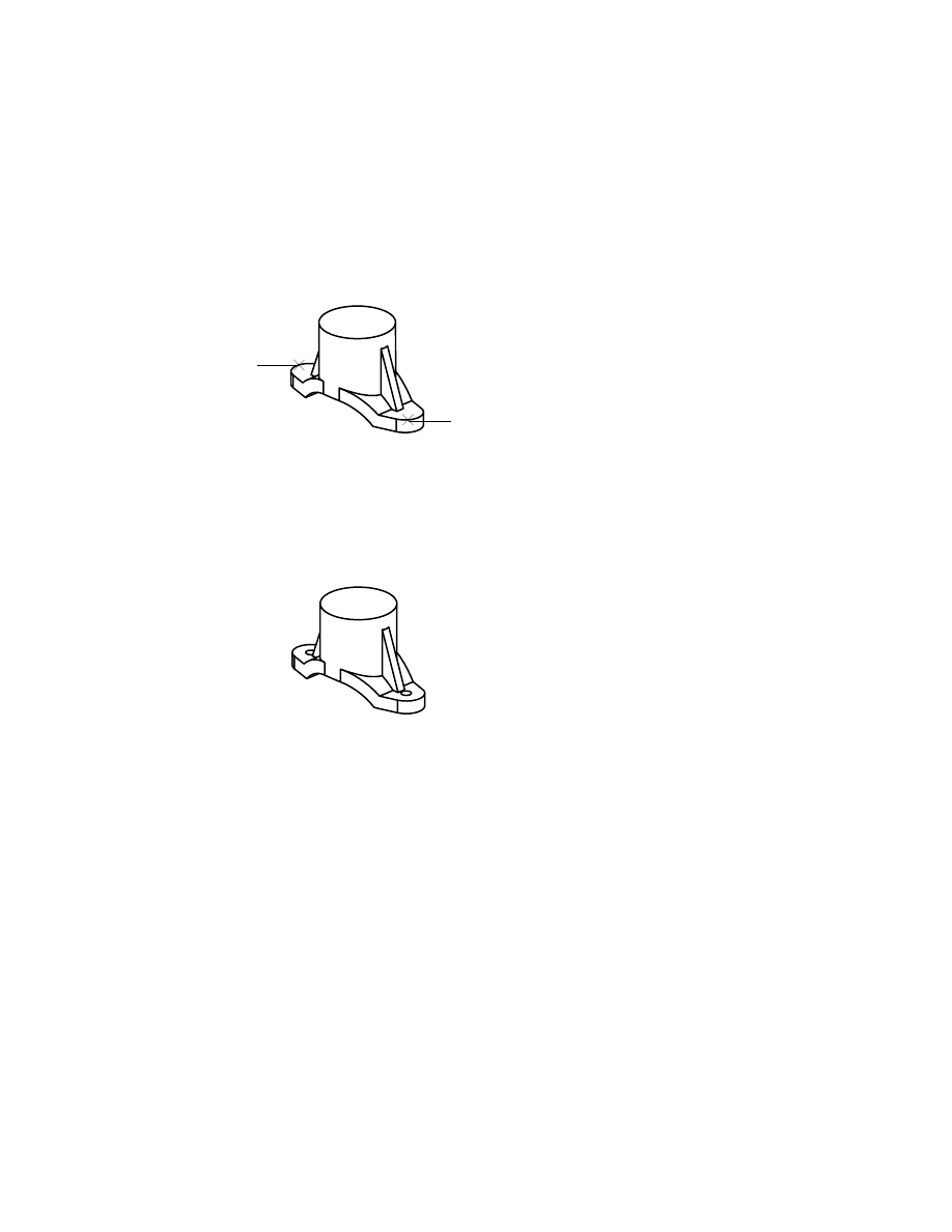
4
Continue on the command line to place the second hole.
Select work plane, planar face or [worldXy/worldYz/worldZx/Ucs]:
Specify face (2)
Select the concentric edge:
Specify edges (2) for the second hole
Select work plane, planar face or [worldXy/worldYz/worldZx/Ucs]:
Press
ENTER
Your part should look like this.
To complete the boss, you create a counterbored hole through the cylinder.
You create the hole as a placed feature on the same vertical work axis as the
cylinder.
Keep the right viewport active, and specify a counterbored hole drilled
through the part, concentric with the cylinder.
1
2
302
|
Chapter 12
Creating Parts
To create a counterbored hole
1
Use
AMHOLE
to place the counterbored hole.
Context Menu
In the graphics area, right-click and choose Placed
Features ➤ Hole.
In the Hole dialog box, select the Counterbore hole type icon and specify:
Termination:
Through
Placement: Concentric
Hole Parameters: Size:
Enter .42
C’Bore/Sunk Size: C’ Dia:
Enter .48
C’Bore/Sunk Size: C’ Depth:
Enter .125
Choose OK.
2
Respond to the prompts as follows:
Select work plane, planar face or [worldXy/worldYz/worldZx/Ucs]:
Specify face (1)
Select the concentric edge:
Specify edge (1)
Select work plane, planar face or [worldXy/worldYz/worldZx/Ucs]:
Press
ENTER
The ribs currently extend too far onto the lug area, leaving little room for the
mounting holes. To adjust the design, you need to reduce the width and
angle of the ribs.
Work in the left viewport. Modify the ribs by changing a few sketch
dimensions. The previously-defined equations keep the ribs symmetrical.
Use the Browser to select the rib feature and redisplay its sketch dimensions.
After you change the dimension values, use the Update icon in the Browser
to incorporate the changes.
1
Refining Parts
|
303
To edit a feature
1
Use
AMEDITFEAT
to edit the rib sketch.
Browser
Right-click OpenProfile1 and choose Edit Sketch.
The rib sketch and its dimensions become visible on the screen.
2
Change two of the dimensions in the sketch, following the prompts.
Context Menu
In the graphics area, right-click and choose Dimensioning
➤ Edit Dimension.
Select object:
Specify the dimension (1)
Enter new value for dimension <40>:
Enter 28
Select object:
Specify the dimension (2)
Enter new value for dimension <.o8>:
Enter .06
Select object:
Press
ENTER
3
Update the part to reflect the new dimension values in the sketch.
Context Menu
In the graphics area, right-click and choose Update Part.
The ribs are updated to reflect your dimensional changes.
In the Browser, each feature is placed in the order it was created.
2
1
304
|
Chapter 12
Creating Parts
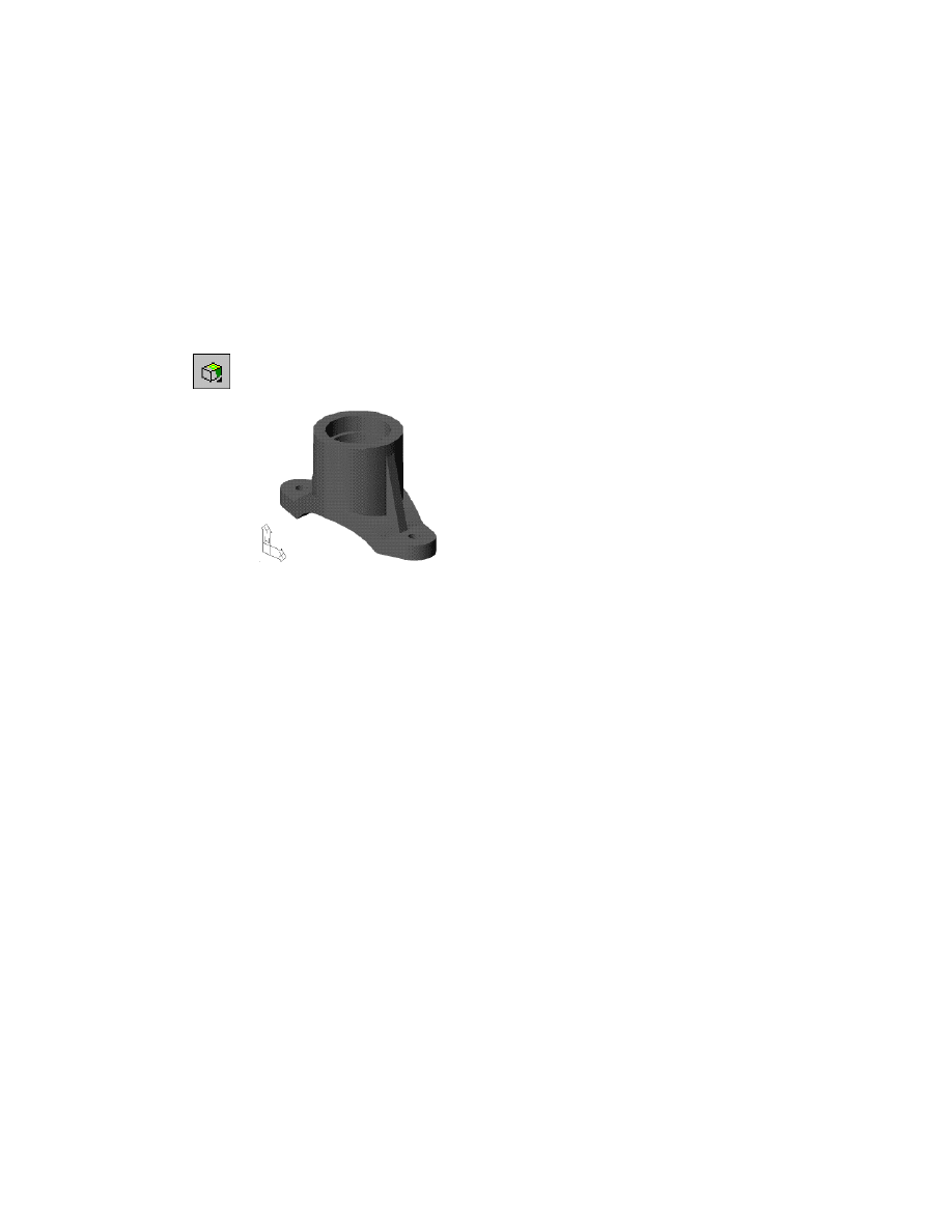
Shading and Lighting Models
To see your model better, use the shade button on the Desktop View toolbar
to toggle shading on. Then adjust the lighting of your shaded model.
To toggle shading of a part
1
Use
SHADE
to shade your part.
Desktop Menu
View ➤ Shade ➤ Gouraud Shaded
Your part should now look like this.
The Desktop View toolbar also contains commands to dynamically rotate
your design and control views.
Now adjust the ambient and direct lighting of your shaded part.
Ambient light provides constant illumination in the drawing environment.
It has no particular source or direction. You can adjust the intensity of ambi-
ent light. Keep ambient light low to prevent washing out your image.
Direct light illuminates your image from a specified direction. You can adjust
the intensity and direction of direct light.
Shading and Lighting Models
|
305
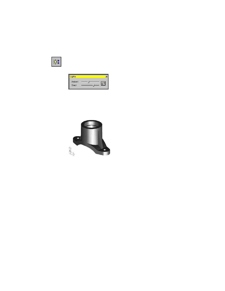
To control the lighting of a shaded part
1
Use
AMLIGHT
to adjust the intensity of ambient and direct light.
Toolbutton
Lighting Control
In the Lights dialog box, use the slider bars to adjust the intensity of the
ambient light and the direct light as follows.
2
Use
AMLIGHTDIR
to specify a direction for direct light.
In the Lights dialog box, click the Light Direction button. Respond to the
prompt as follows:
Select a point that will be used with the current target point for light direction:
Specify a point in the upper left of the graphics area
The light adjustments are reflected in your drawing. Experiment with other
light settings.
Save your file.

306
Wyszukiwarka
Podobne podstrony:
Ch12 Shafts with Standard Parts
Ch12 Shafts with Standard Parts
Okidata Okipage 14e Parts Manual
Kyocera FS 1010 Parts Manual
Brother PT 2450 Parts Manual
A10VO Series 31 Size 28 Service Parts list
Fly Model 030 B17G interiors some custom parts
PARTS MANUAL TL120 BT3Z001 1(21200008~)
Body Parts 3
Dynapower Model 66 & 99 Modular Controls Parts
Body Parts 2
Kyocera Paper Feeder PF 60 Parts Manual
Ch12 E1
więcej podobnych podstron