
BODY (INTERIOR
AND EXTERIOR)
Return To Main Table of Contents
GENERAL . . . . . . . . . . . . . . . . . . . . . . . . . . . . . . . . . . . . . . . . . . . . . .
BODY PANELING . . . . . . . . . . . . . . . . . . . . . . . . . . . . . . . . . . . . . .
BODY DIMENSIONS . . . . . . . . . . . . . . . . . . . . . . . . . . . . . . . . . .
GRILLE AND MOULDINGS . . . . . . . . . . . . . . . . . . . . . . . . . . . .
BUMPER . . . . . . . . . . . . . . . . . . . . . . . . . . . . . . . . . . . . . . . . . . . . . .
WINDSHIELD . . . . . . . . . . . . . . . . . . . . . . . . . . . . . . . . . . . . . . . . . .
REAR WINDOW GLASS . . . . . . . . . . . . . . . . . . . . . . . . . . . . . . .
QUARTER FIXED GLASS . . . . . . . . . . . . . . . . . . . . . . . . . . . . .
QUARTER SWIVELING GLASS . . . . . . . . . . . . . . . . . . . . . . .
FRONT DOOR . . . . . . . . . . . . . . . . . . . . . . . . . . . . . . . . . . . . . . . .
REAR DOOR . . . . . . . . . . . . . . . . . . . . . . . . . . . . . . . . . . . . . . . . . .
TRUNK LID . . . . . . . . . . . . . . . . . . . . . . . . . . . . . . . . . . . . . . . . . . .
TAILGATE.. . . . . . . . . . . . . . . . . . . . . . . . . . . . . . . . . . . . . . . . . . . .
INTERIOR TRIM . . . . . . . . . . . . . . . . . . . . . . . . . . . . . . . . . . . . . . .
CONSOLE . . . . . . . . . . . . . . . . . . . . . . . . . . . . . . . . . . . . . . . . . . . . .
CRASH PAD . . . . . . . . . . . . . . . . . . . . . . . . . . . . . . . . . . . . . . . . . .
FRONT SEAT . . . . . . . . . . . . . . . . . . . . . . . . . . . . . . . . . . . . . . . . .
REAR SEAT . . . . . . . . . . . . . . . . . . . . . . . . . . . . . . . . . . . . . . . . . . .
SEAT BELT. . . . . . . . . . . . . . . . . . . . . . . . . . . . . . . . . . . . . . . . . . . . 73
SUNROOF . . . . . . . . . . . . . . . . . . . . . . . . . . . . . . . . . . . . . . . . . . . . . 75
PASSIVE SEAT BELT . . . . . . . . . . . . . . . . . . . . . . . . . . . . . . . . . .

GENERAL
G E N E R A L
SPECIFICATIONS
Flood
Type
Front door
Construction
Regulator system
Locking system
Rear door
Construction
Regulator system
Locking system
Trunk lid
Type
Tailgate
Type
Quarter swiveling window
Type
Glass thickness
Windshield glass
Quarter fixed glass
Rear window glass
Tailgate window glass
Quarter swiveling glass,
Distance between door upper hinge
and lower hinge
Seat
Front seat travel
Seat belt
Front
Rear
Rear hinged, Front opening type
Front hinged, full door construction
Wire drum type
Pin-fork system
Front hinged, full door construction
Wire drum type
Pin-fork system
Torsion bar type
Inner hinged, gas lift type
Front hinged, rear opening type
Zone tempered clear, tinted
Laminated clear, tinted
Front door 347 mm (13.7 in.)
Rear door 322 mm (12.7 in.)
220 mm (8.7 in.) by 15 mm (0.6 in.) steps
3 point type with W.L.R
3 point type with E.L.R with 2 point static
5 (0.20)
5 (0.20)
3.2 (0.13)
3.2 (0.13)
3.2 (0.13)
3.2 (0.13)
E.L.R : Emergency Locking Retractor
W.L.R : Webbing Clamp Emergency Locking Retractor
6 0 - 2

TIGHTENING TORQUE
Nm
kg.cm
lb.ft
Front and rear doors
Door hinge to body
Door hinge to door
Trunk lid
Trunk lid hinge to body
Trunk lid hinge to trunk lid
Tailgate
Tailgate hinge to body
Tailgate hinge to tailgate
Hood
Hood hinge to body
Hood hinge to hood
Hood latch to body
Seat
Front seat to floor Nut
Bolt
Seat belt
Front seat belt retractor to center pillar
Rear seat belt anchorage
Passive set belt & lap belt retractor
3 6 - 4 2
3 6 0 - 4 2 0
2 6 - 3 0
1 3 - 2 6
1 3 0 - 2 6 0
9 - 1 9
7 - 9
7 0 - 9 0
5 - 6 . 5
7 - 9
7 0 - 9 0
5 - 6 . 5
2 8 - 3 5
2 8 0 - 3 5 0
2 0 . 2 - 2 5 . 3
2 8 - 3 5
2 8 0 - 3 5 0
2 0 . 2 - 2 5 . 3
9 - 1 4
9 0 - 1 4 0
6 . 5 - 1 0
2 2 - 2 7
2 2 0 - 2 7 0
1 6 - 1 9 . 5
7 - 9
7 0 - 9 0
5 - 6 . 5
2 4 - 3 6
2 4 0 - 3 6 0
17.4-26
3 5 - 5 5
3 5 0 - 5 5 0
2 5 . 3 - 4 0
4 0 - 4 5
4 0 - 4 5
4 0 - 4 5
4 0 0 - 4 5 0
4 0 0 - 4 5 0
4 0 0 - 4 5 0
2 9 - 3 3
2 9 - 3 3
2 9 - 3 3
6 0 - 3
GENERAL
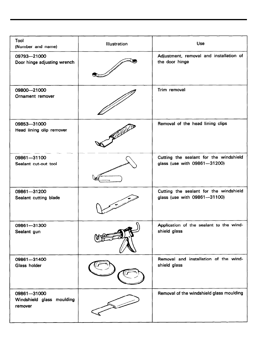
SPECIAL TOOLS
6 0 - 4

GENERAL
TROUBLESHOOTING
Symptom
Sunroof
Water leaks
Probable cause
Remedy
Dust accumulated in drainage of housing
Clean dust from inside of drain
assembly
pipe
Clogged drain pipe
Blow air into drain pipe to remove
dust
Broken or dislocated drain pipe, defective or
Check pipe installation and flange
cracked clip
contact
Deteriorated roof lid weatherstrip
Replace
Excessive roof lid-to body clearance and Adjust
improperly fitted weatherstrip
Wind noise
Loose or deformed deflector
Retighten or replace
Roof lid makes noise
Foreign matter lodged in guide rail
Check drive cable and guide rails
when moved
for foreign matter
Loose guide rails and lid
Retighten
Motor runs but lid does
Foreign matter lodged in guide rail
Check drive cable and guide rails
not move or moves only
for foreign matter
halfway
Incorrect engagement of motor pinion with
Check for loose motor installation
drive cable
and damaged pinion
Decrease in clutch slipping force of motor
Adjust
Increased lid sliding resistance or interfer-
Adjust or replace
ence of lid with drive cables, weatherstrip,
etc. due to maladjustment of lid
Noise in motor (Clutch
Incorrect engagement of motor pinion with
Check pinion installation and
slipping noise made in
drive cable
retighten motor
motor when lid is fully
Worn or damaged motor pinion bearing
Replace motor assembly
opened or closed is not
Worn or deformed drive cable
Replace
unusual noise.)
Door glass fails to
operate up and down
Door does not open
or close completely
Hood does not open
or close completely
Water leak through
windshield and rear
window
Incorrect window glass installation
Adjust position
Damaged or faulty regulator arm or regulator
Correct or replace
Incorrect door installation
Adjust position
Defective door check
Correct or replace
Door hinge requires grease
Apply grease
Striker and latch not properly aligned
Adjust
Incorrectly installed hood
Adjust
Incorrect hood bumper height
Adjust
Defective seal
Fill will sealant
Defective body flange
Correct
6 0 - 5

GENERAL
Symptom
Wind noise around door
Probable cause
Weatherstrip not holding firmly
Improperly installed weatherstrip or setting of
weatherstrip
Improperly closed door
Improperly fit door
Improper clearance between door glass and
division channel
Deformed door
Remedy
Adjust fit of door
Repair or replace
Adjust
Adjust
Adjust
Repair or replace
6 0 - 6
BODY PANELING
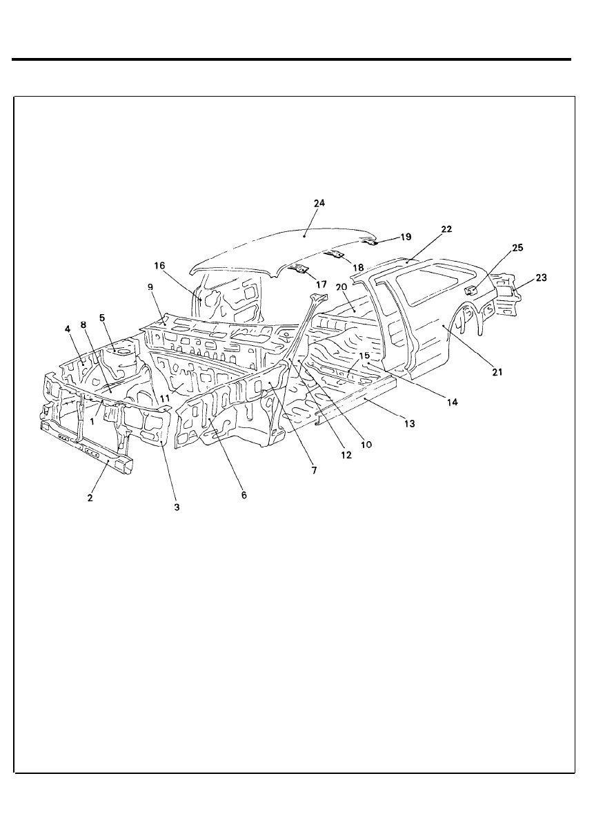
BODY PANELING
COMPONENTS
3-Door model
1. Member assy, radiator support upper
2. Member assy, radiator support lower
3. Panel assy, radiator support
4. Panel assy, fender apron inner front
5. Panel assy, shock absorber housing
6. Panel assy, fender apron upper outer
7. Panel assy, cowl side inner upper
8. Member assy, front side
9. Panel assy, cowl top outer
10. Panel assy, cowl inner lower
11. Panel assy, dash
12. Panel assy, front pillar
13. Panel assy, side sill
14. Panel assy, front floor
15. Member assy, front seat cross
16. Panel assy, door
17. Rail assy, roof front
18. Rail assy, roof center
19. Rail assy, roof rear
20. Panel assy, rear floor
21. Panel assy, quarter outer
22. Panel assy, quarter inner
23. Panel assy, back
24. Panel, roof
25. Door, fuel filler
6 0 - 7
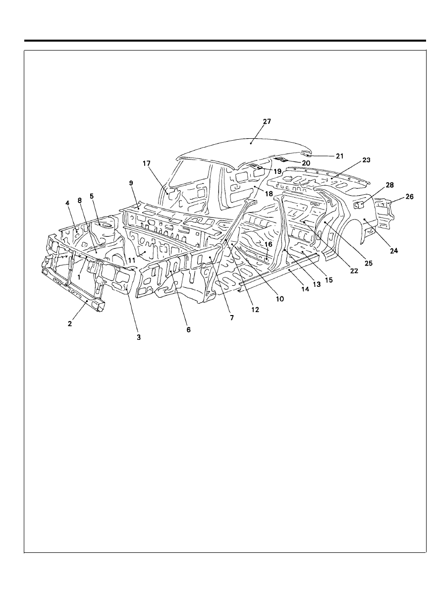
BODY PANELING
COMPONENTS
4-Door model
1. Member assy, radiator support upper
2. Member assy, radiator support lower
3. Panel assy, radiator support
4. Panel assy, fender apron inner front
5. Panel assy, shock absorber housing
6. Panel assy, fender apron upper outer
7. Panel assy, cowl side inner upper
8. Member assy, front side
9. Panel, assy, cowl top outer
10. Panel assy, cowl inner lower
11. Panel assy, dash
12. Panel assy, front pillar
13. Panel assy, center pillar
14. Panel assy, side sill
15. Panel assy, front floor
16. Member assy, front seat cross
17. Panel assy, door
18. Rail assy, rear door
19. Rail assy, roof front
20. Rail assy, roof center
21. Rail assy, roof rear
22. Panel assy, rear floor
23. Panel assy, rear package tray
24. Panel assy, quarter outer
25. Panel assy, quarter inner
26. Panel assy, back
27. Panel, roof
28. Door, fuel filler
6 0 - 8
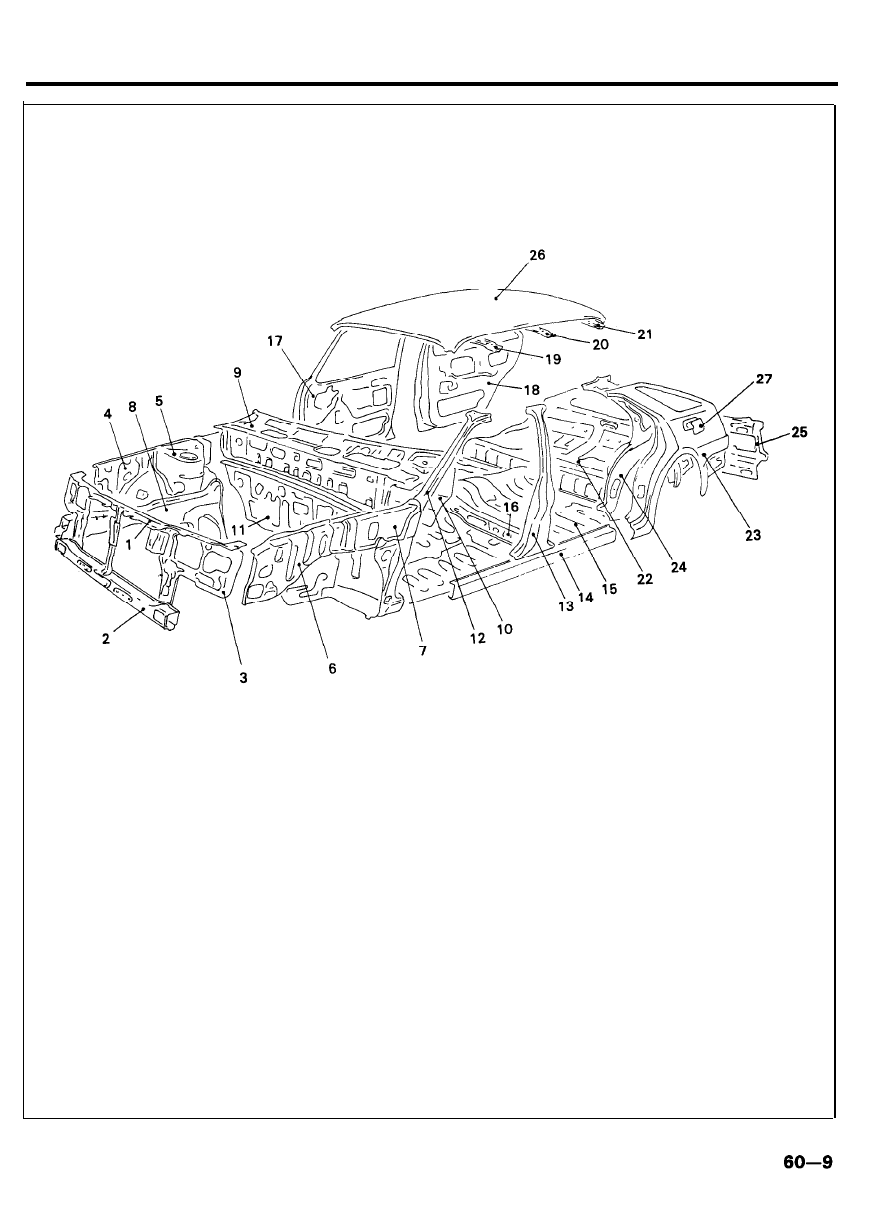
BODY PANELING
COMPONENTS
5-Door model
1. Member assy, radiator support upper
2. Member assy, radiator support lower
3. Panel assy, radiator support
4. Panel assy, fender apron inner front
5. Panel assy, shock absorber housing
6. Panel assy, fender apron upper outer
7. Panel assy, cowl side inner upper
8. Member assy, front side
9. Panel assy, cowl top outer
10. Panel assy, cowl inner lower
11. Panel assy, dash
12. Panel assy, front pillar
13. Panel assy, center pillar
14. Panel assy, side sill
15. Panel assy, front floor
16. Member assy, front seat cross
17. Panel assy, door
18. Rail assy, rear door
19. Rail assy, roof front
20. Rail assy, roof center
21. Rail assy, roof rear
22. Panel assy, rear floor
23. Panel assy, quarter outer
24. Panel assy, quarter inner
25. Panel assy, back
26. Panel, roof
27. Door, fuel filler
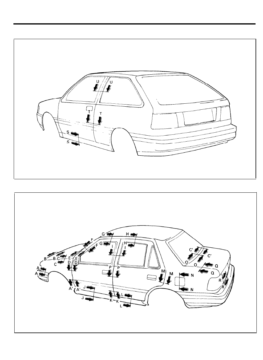
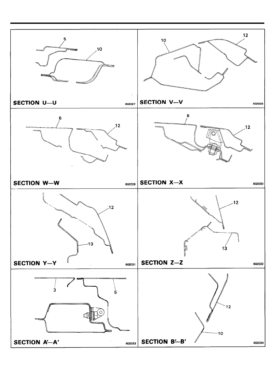
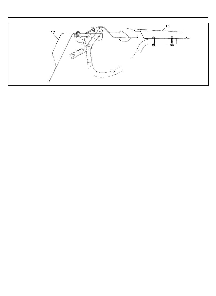
BODY PANELING
CROSS-SECTIONAL VIEWS
3-Door model
4-Door model
6 0 - 1 0
BODY PANELING
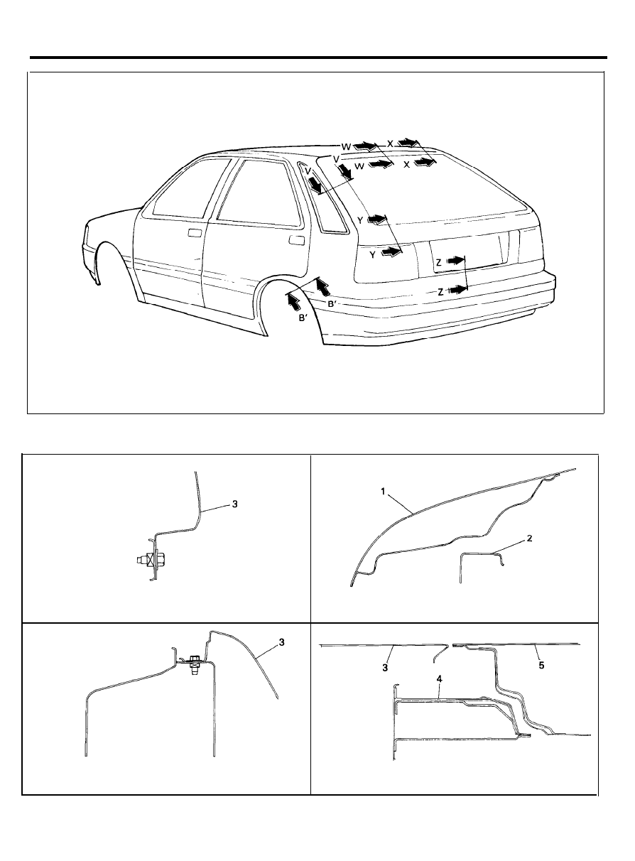
5-Door model
S E C T I O N A - A
SECTION B-B
SECTION C-C
SECTION D-D
6 0 - 1 1
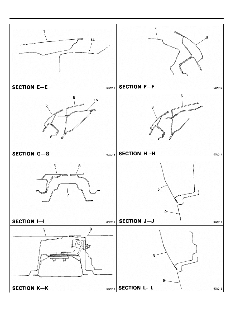
BODY PANELING
6 0 - 1 2
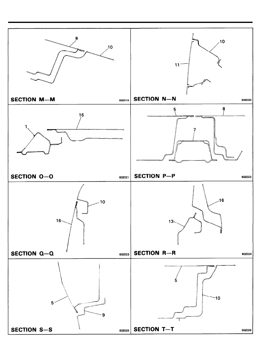
BODY PANELING
6 0 - 1 3
BODY PANELING
6 0 - 1 4
BODY PANELING
S E C T I O N C ’ - C ’
1. Panel assy, hood
2. Panel assy, radiator support
3. Panel assy, fender
4. Pillar assy, front
5. Panel assy, front door
6. Panel assy, roof
7. Pillar assy, center
8. Panel assy, rear door
9. Panel assy, side sill
10. Panel assy, quarter
11. Panel assy, fuel filler door
12. Panel assy, tailgate
13. Panel assy, back
14. Panel assy, cowl top
15. Rail assy, roof side
16. Panel assy, trunk lid
17. Panel assy, rear package tray
6 0 - 1 5
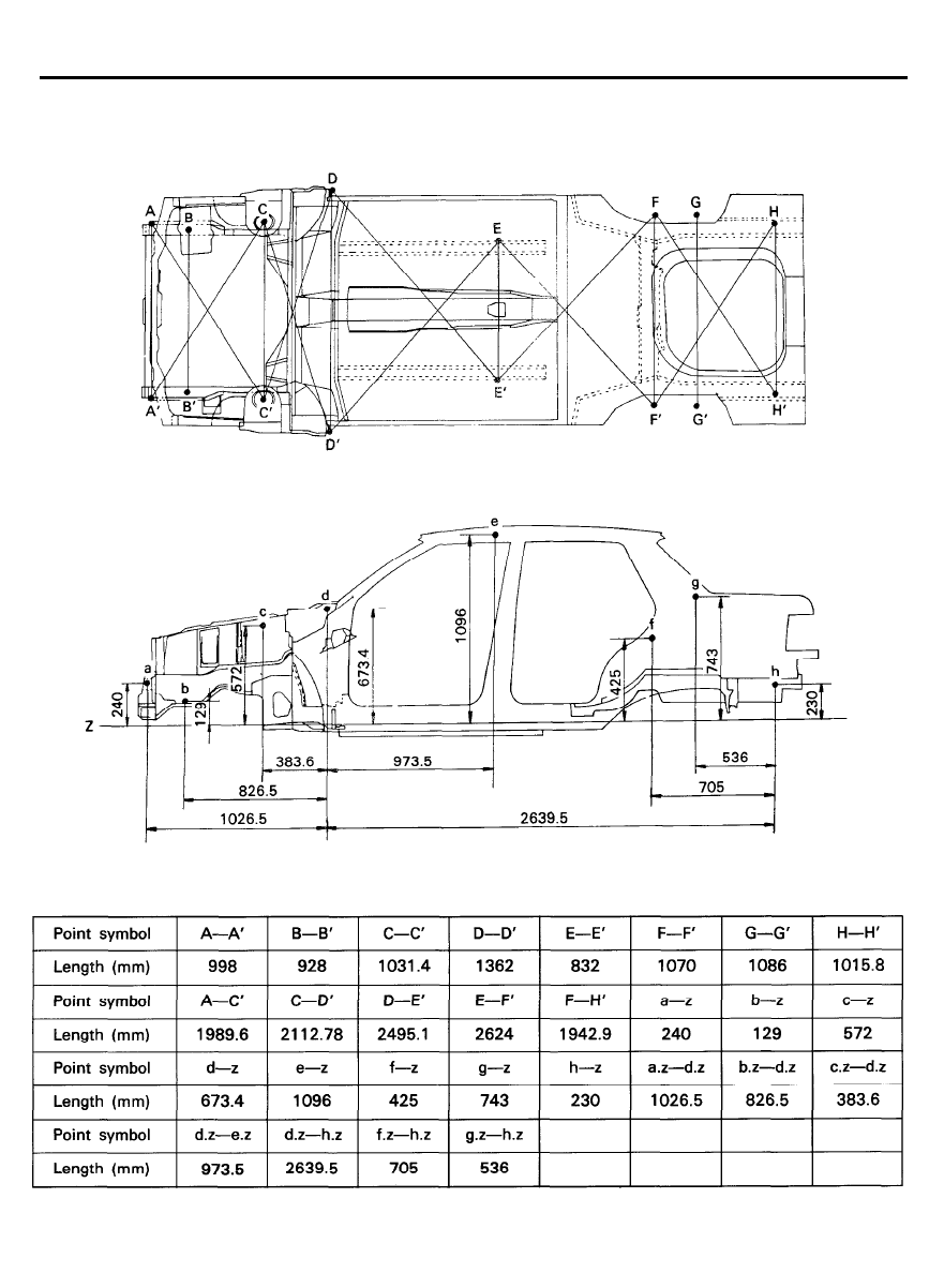
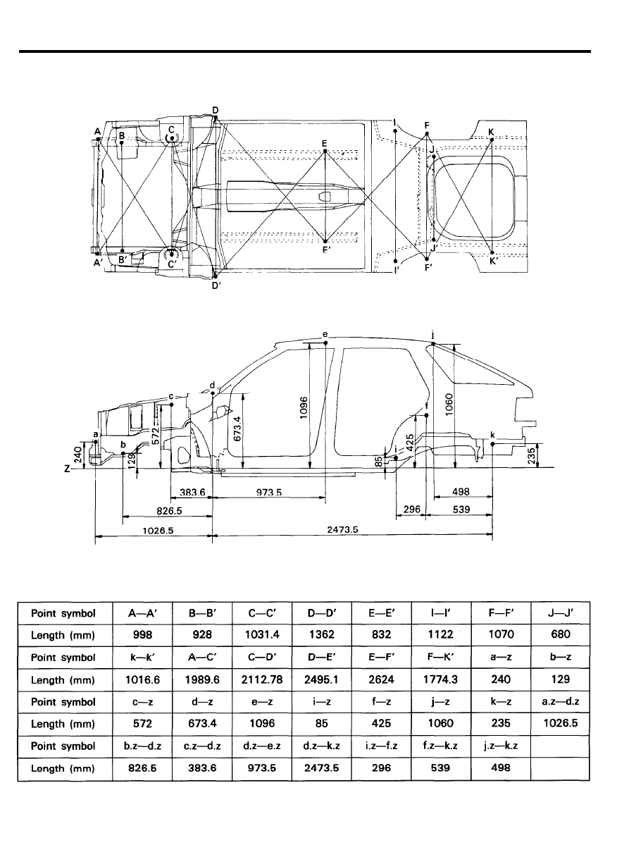
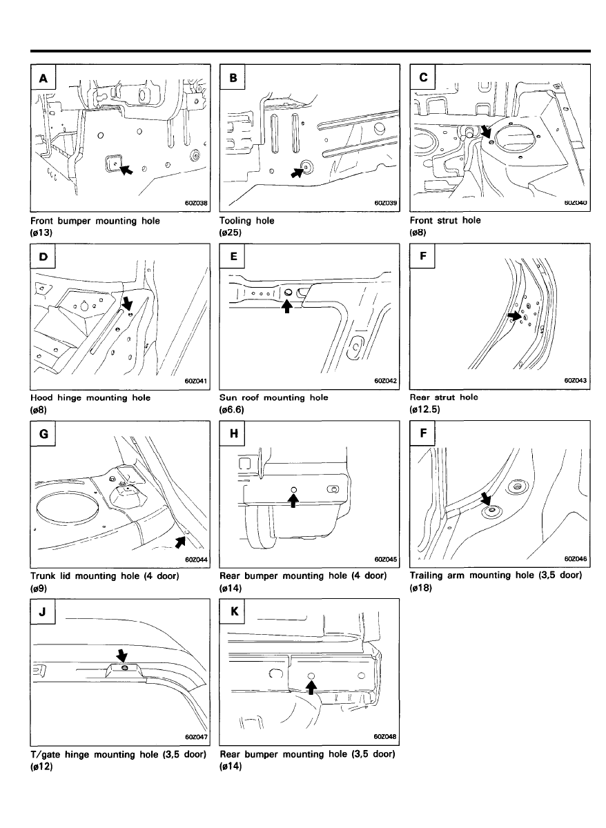
BODY DIMENSIONS
UNDER BODY
4 DOOR
6 0 - 1 6
BODY DIMENSIONS
3 / 5 D O O R
6 0 - 1 7
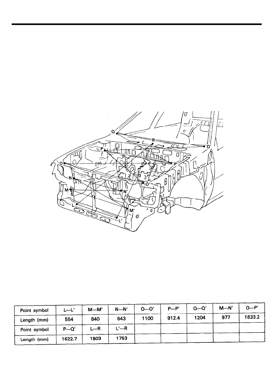
BODY DIMENSIONS
6 0 - 1 8
BODY DIMENSIONS
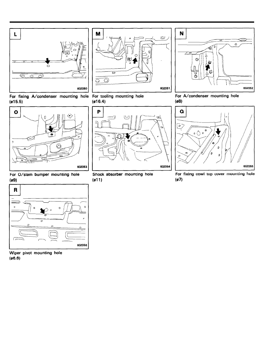
E N G I N E C O M P A R T M E N T
6 0 - 1 9
BODY DIMENSIONS
6 0 - 2 0
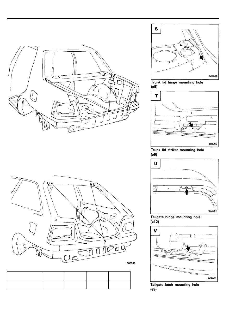
BODY DIMENSIONS
4 DOOR
3 / 5
D O O R
Point symbol
S - T
S ' - T
U - V
U ' - V
Length (mm)
1624
1582
1656
1566
6 0 - 2 1
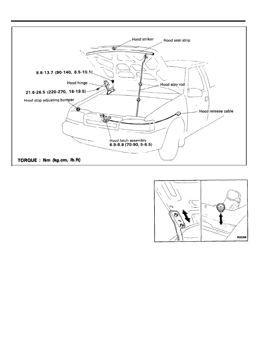
HOOD
COMPONENTS
ADJUSTMENT
Hood Hinge
1. Loosen the hood hinge mounting bolt.
2. Adjust the longitudinal and lateral positions of the hood by
utilizing the oblong holes in the hinge.
3. Adjust front edge of hood in vertical direction by adjusting
the hood stop adjusting bolts.
Hood Latch
1. Loosen the hood lock mounting bolts.
2. Adjust the alignment of the hood latch by adjusting the
longitudinal and lateral position of the lock, and by adjusting
the height of the hood.
6 0 - 2 2
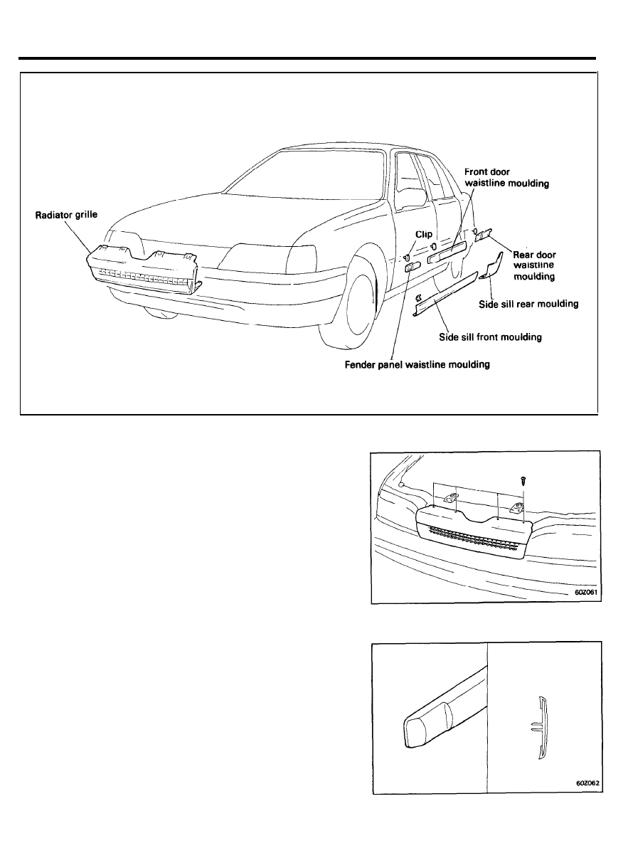
GRILL AND MOULDING
COMPONENTS
REMOVAL
Radiator Grille
1. Remove the radiator grille after unscrewing the tapping
screws.
Waistline Moulding
1. Beginning from either end, remove the waistline moulding
from the fender panels and the front and rear doors.
6 0 - 2 3
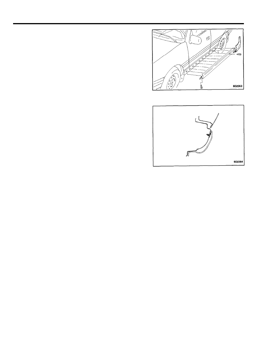
GRILL AND MOULDING
Side Sill Moulding
1.
After removal of the rear side sill moulding, remove the front
side sill moulding.
INSTALLATION
1. Clean the surfaces of the body to which adhesive will be
applied by using a wax and grease remover.
6 0 - 2 4
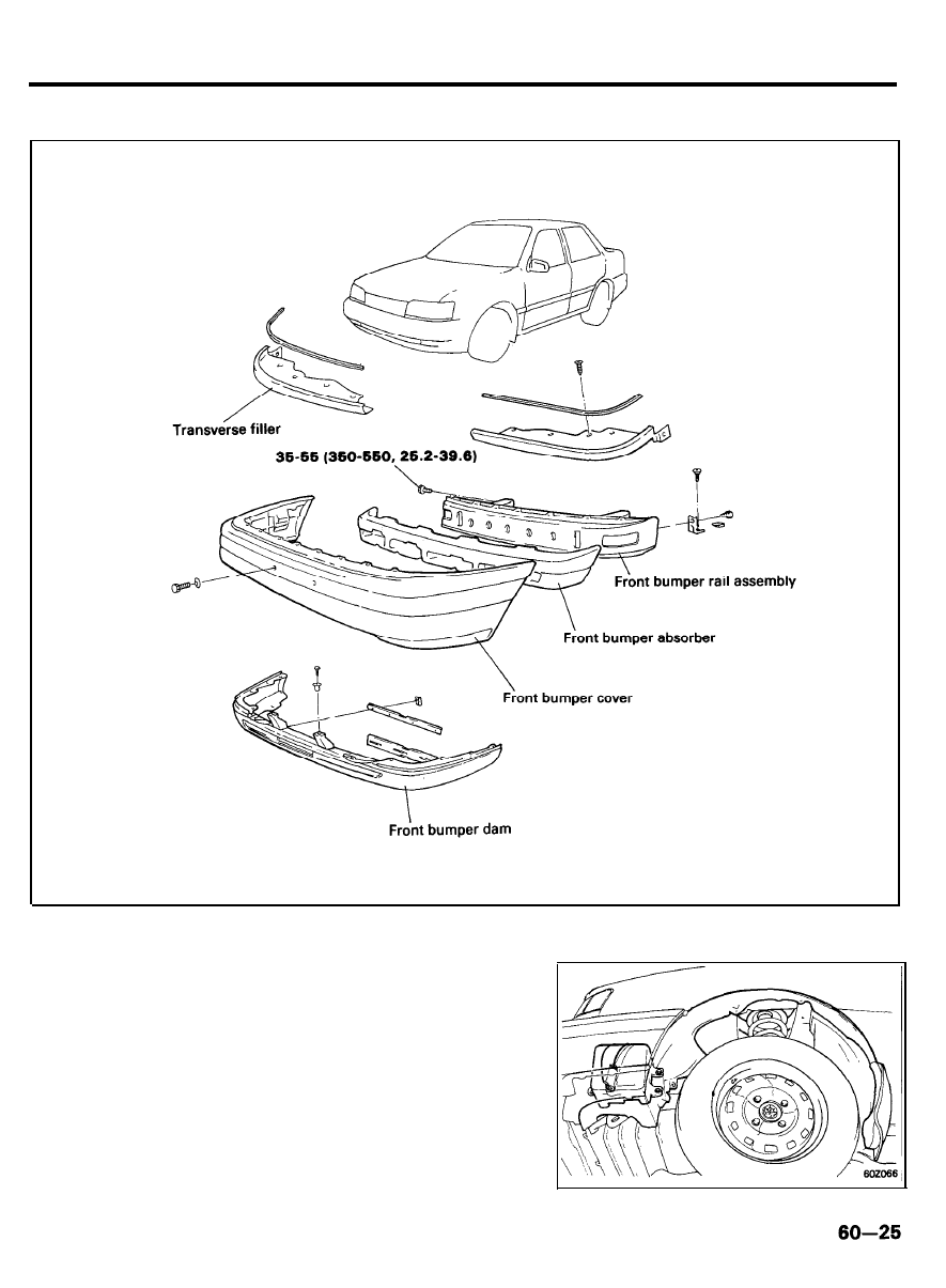
BUMPER
FRONT BUMPER
COMPONENTS
TORQUE : Nm (kg.cm, lb.ft)
REMOVAL
1. Remove the front wheel guard and reservoir tank.
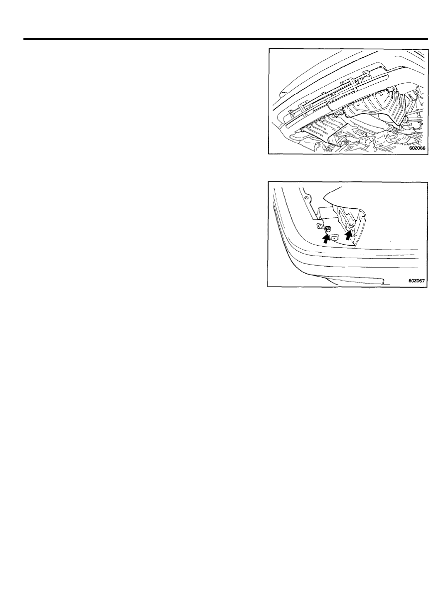
BUMPER
2.
Remove the mounting bolts from the lower side of the front
bumper dam.
3.
Remove the bumper stay-to body bolts and remove the front
bumper.
INSTALLATION
1. Installation is the reverse of the removal procedure.
6 0 - 2 6
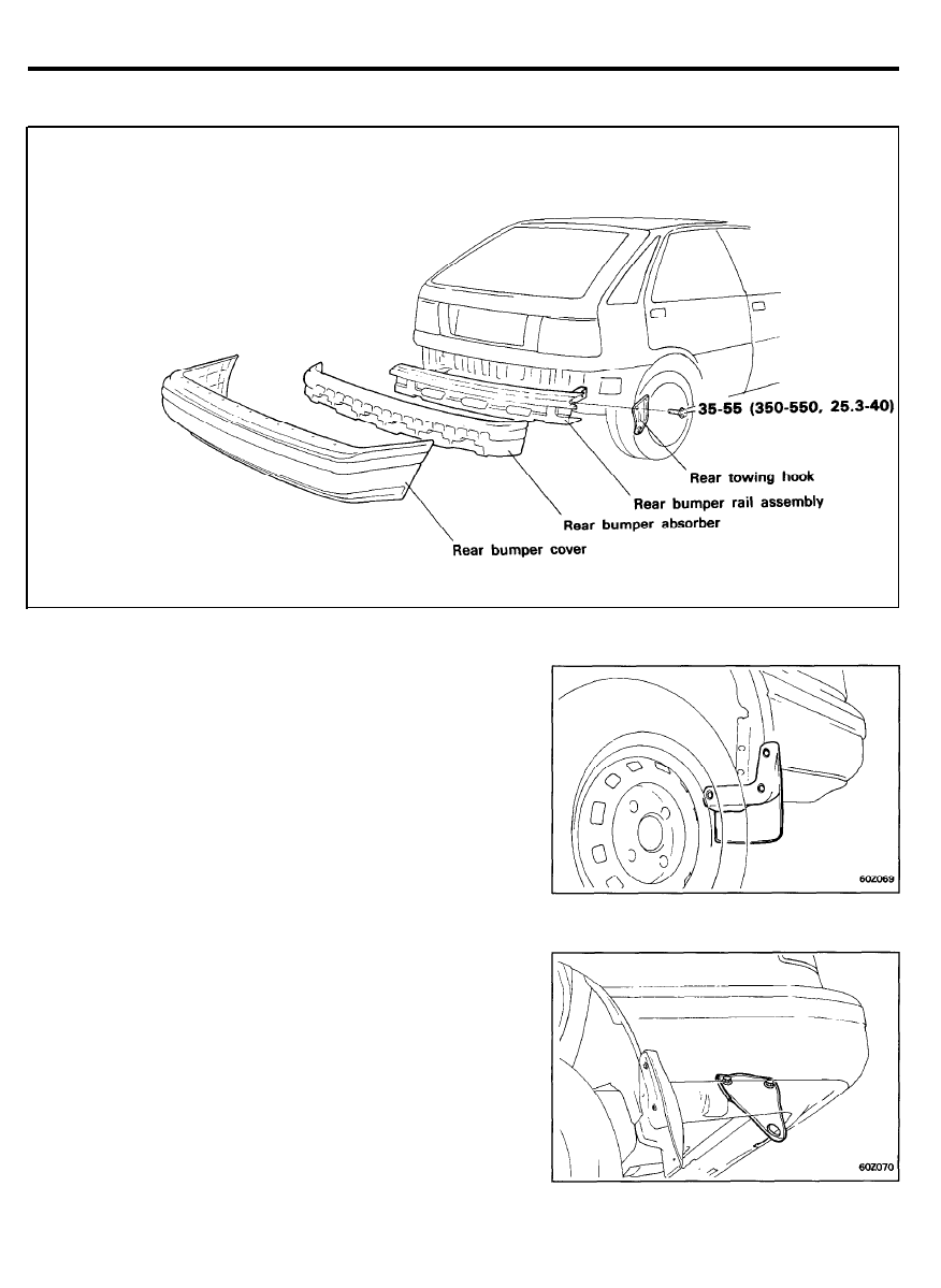
BUMPER
REAR BUMPER
COMPONENTS
TORQUE : Nm (kg.cm, lb.ft)
REMOVAL
1. Remove the mud guard and the wheel guard.
2. Remove the bumper stay-to-body bolts.
6 0 - 2 7
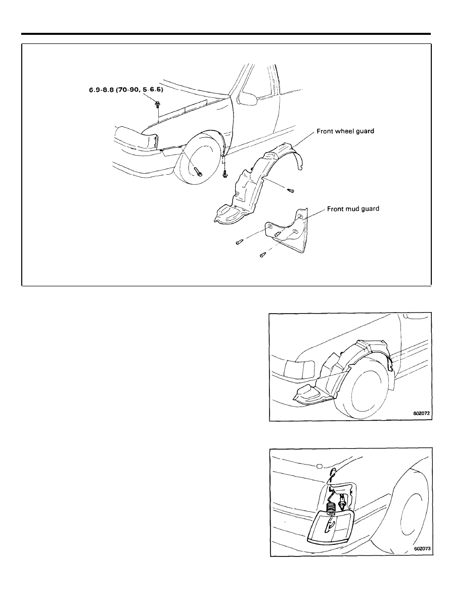
FENDER
COMPONENTS
TORQUE : Nm (kg.cm, Ib.ft)
REMOVAL
1. Remove the mud guard and wheel guard by loosening the
screws.
2. Disconnect the side marker lamp connector.
3. Remove the side marker lamp.
6 0 - 2 8
FENDER
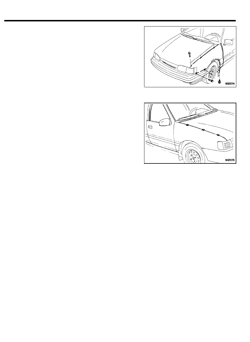
4. Remove the fender mounting bolts.
CAUTION
Use care to avoid damaging the paint.
INSTALLATION
1. Installation is the reverse of the removal procedure.
NOTE
In order to prevent the fender mounting bolts area from
forming rust, apply tape sealer between the fender and the
body panel.
6 0 - 2 9
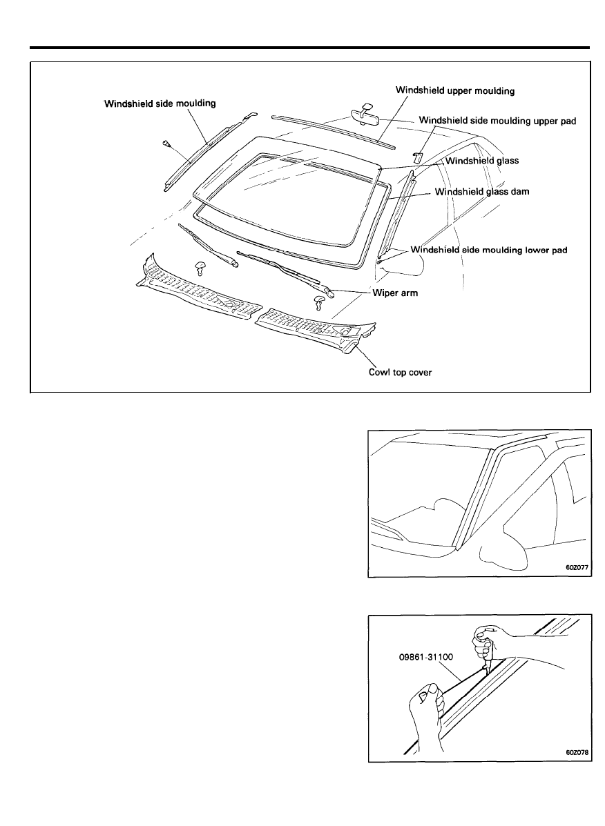
WINDSHIELD
COMPONENTS
REMOVAL
1.
To remove the windshield, first remove the following parts;
1) Front pillar trims
2) Wiper arms
3)
Cowl top cover
4) Side mouldings
2.
Use the special tool to cut through the windshield sealant.
6 0 - 3 0
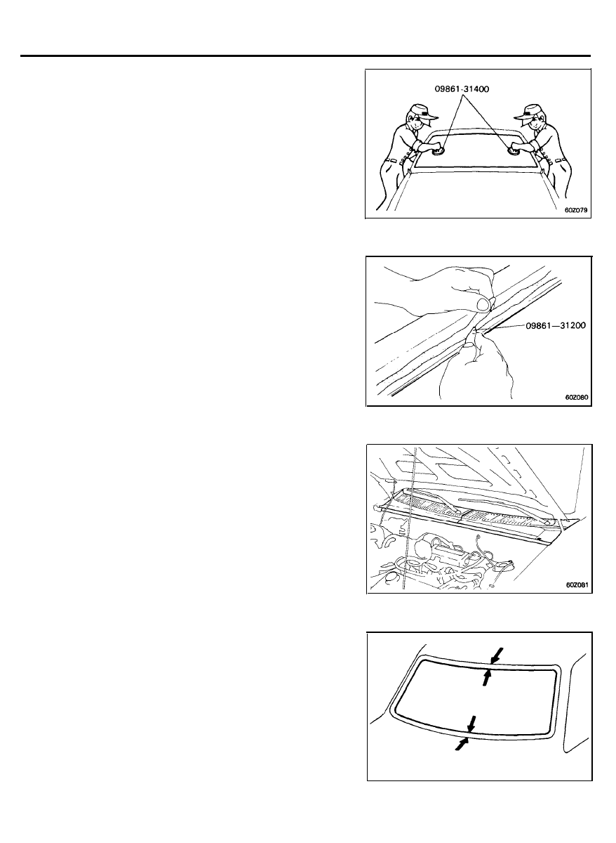
WINDSHIELD
3.
Make mating marks on the glass and body if the glass is to
be reinstalled.
NOTE
Use chalk or equivalent to make mating marks on the glass
and body.
4.
Take out the windshield glass with special tool, Glass Holder.
INSTALLATION
1.
Using a cutter knife or the special tool, scrape the old sealant
to a thickness or about 2 mm on the bonding surface around
the entire windshield flange.
CAUTION
Be careful not to remove more adhesive than necessary,
and also not to damage the paintwork on the body surface
with the knife. If the paintwork is damaged, repair the
damaged area with touch-up paint.
2.
Clean the body bonding surface with a sponge dampened in
alcohol or wax and grease remover.
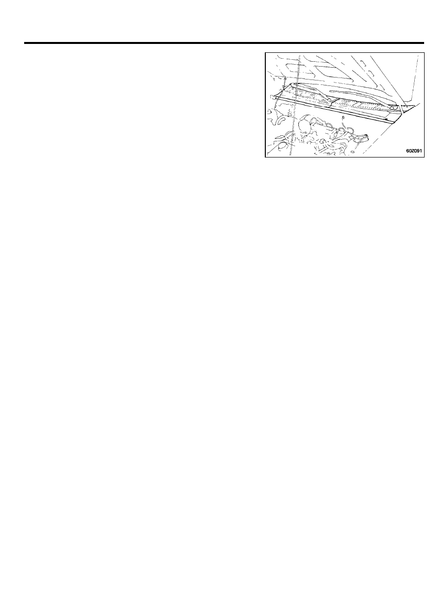
3.
Install the cowl top cover mounting retainers at the locations
as shown in illustration.
4. Center a new windshield in the opening.
mark the location by scribing lines across the glass and body
with a grease pencil at four points as shown.
6 0 - 3 1
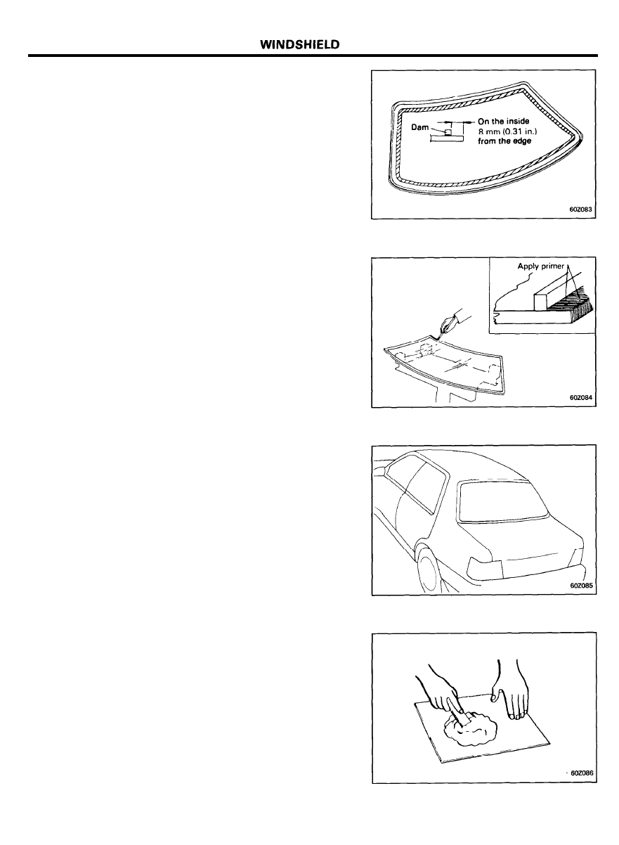
5.
Glue the rubber dam to the inside surface of the windshield
around the entire edge as shown, to contain the sealant
during installation.
6.
Apply a light coat of glass primer to the outside of the dam.
NOTE
1) Do not apply body primer to the glass.
2) Never touch the primed surfaces with your hand.
If you do, the adhesive may not bond to the glass
properly, causing a leak after the windshield is
installed.
3) Keep water, dust, and abrasive materials away from
the primed surface.
7. Apply a light coat of body primer to the original sealant
remaining around the window opening flange. The glass
should be installed 10 minutes after you apply the primer.
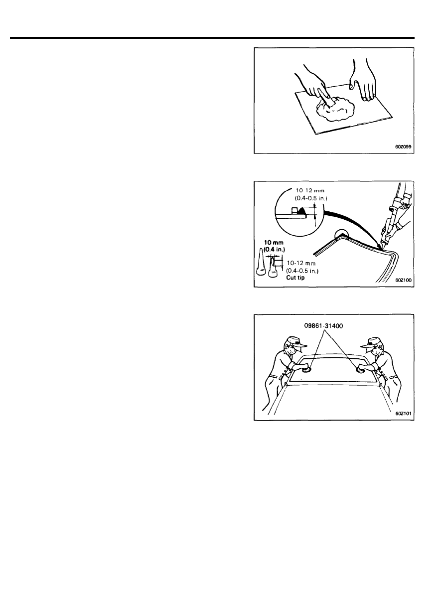
8. Thoroughly mix all the sealant and hardener together on a
glass or metal plate with a putty knife.
NOTE
1) Clean the plate with a sponge and alcohol before
mixing.
2) Follow the instructions that come with the sealant.
6 0 - 3 2
WINDSHIELD
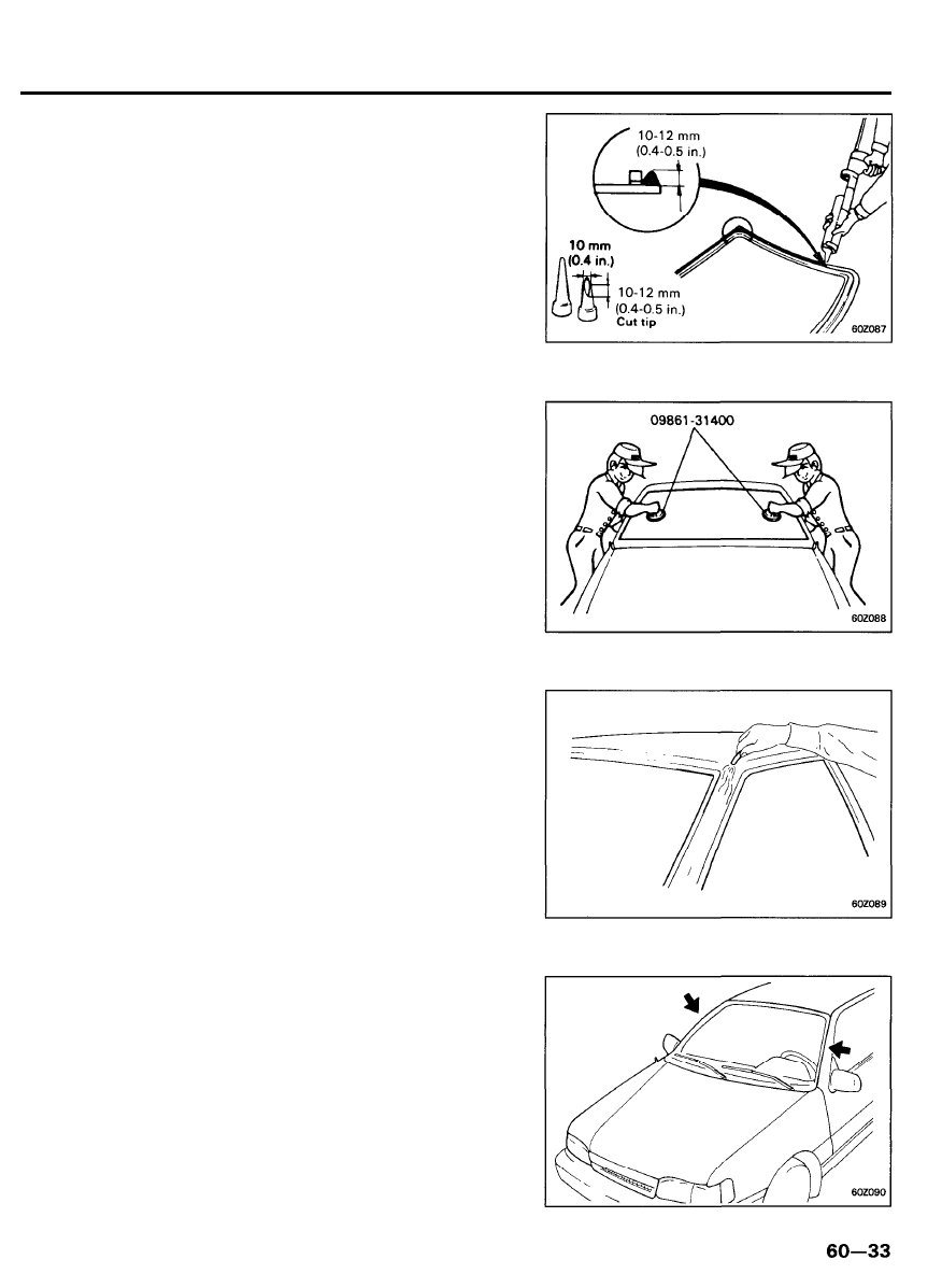
9. Pack adhesive into the cartridge avoiding air pockets, to
ensure continuous delivery. Put the cartridge in a caulking
gun or Sealant Gun, and run a bead of adhesive around the
edge of the glass as shown.
NOTE
Apply the adhesive within 5 minutes after applying the
glass primer.
10. Use suction cups or special tool, lower the glass over the
opening, align it with the marks made in step 5 and set it
down on the sealant. Insert two lower spacers to prevent the
windshield from moving downward.
11. Scrape or wipe excess adhesive off with putty knife or gauze.
Fill all cavities around the windshield.
12. Perform the water-test for the windshield
Use a cold water spray, being careful not to direct a powerful
stream of water on the new adhesive material. allow water
to spill over the edges of the glass.
13. If there are leaks, apply sealant at the leak points.
14. Install the windshield side moulding.
WINDSHIELD
15. Install the cowl top cover.
Reinstall the front pillar trims and wiper arms.
CAUTION
Make sure the sealant has set sufficiently before putting
the vehicle back into operation.
6 0 - 3 4
REAR WINDOW GLASS
COMPONENTS
R E M O V A L
1. Remove the defogger wire connector.
6 0 - 3 5
REAR WINDOW GLASS
2.
To remove the rear window glass, first remove the following
parts;
1) Rear pillar garnish
2) Rear seat belt anchor bolt
3) High mounted stop lamp
4) Package tray trim
3. Remove the rear window glass assembly.
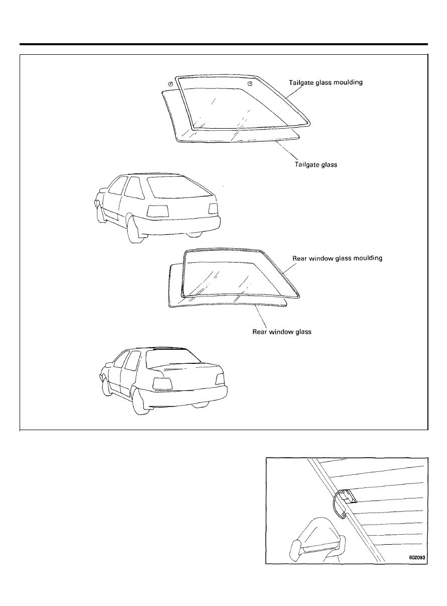
INSTALLATION
1.
Install the rear window glass moulding to the rear window
glass.
2.
Apply a light coat of glass primer to the outside of the dam.
NOTE:
1) Do not apply body primer to the glass.
2) Never touch the primed surfaces with your hand.
If you do, the adhesive may not bond to the glass
properly, causing a leak after the windshield is
installed.
3) Keep water, dust, and abrasive materials away from
the primed surface.
3. Apply a light coat of body primer to the original sealant
remaining around the window opening flange. The glass
should be installed 10 minutes after you apply the primer.
6 0 - 3 6
REAR WINDOW GLASS
4.
Thoroughly mix all the sealant and hardener together on a
glass or metal plate with a putty knife.
NOTE:
1) Clean the plate with a sponge and alcohol or wax or
grease remover before mixing.
2) Follow the instructions that come with the sealant.
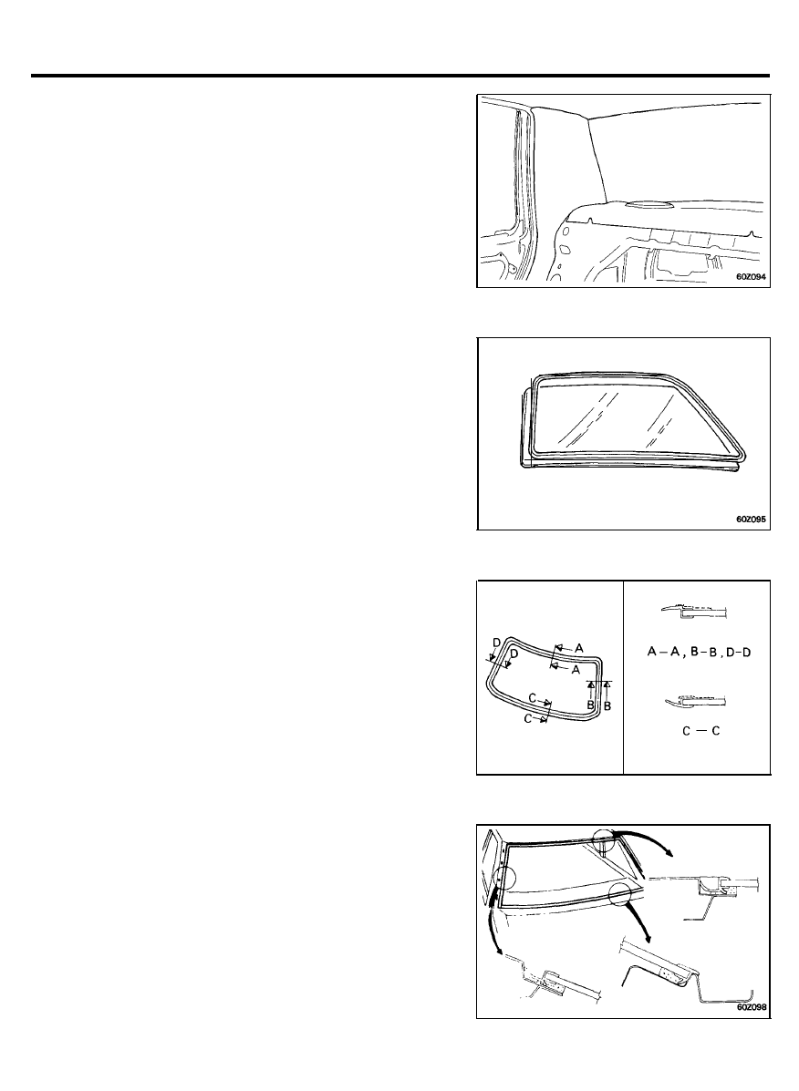
5.
Pack adhesive into the cartridge (avoid air pockets), to ensure
continuous delivery. Put the cartridge in a caulking gun or
Sealant Gun, and run a bead of adhesive around the edge
of the glass as shown.
NOTE:
Apply the adhesive within 5 minutes after applying the
glass primer.
6. Using the special tool, install the rear window glass.
6 0 - 3 7
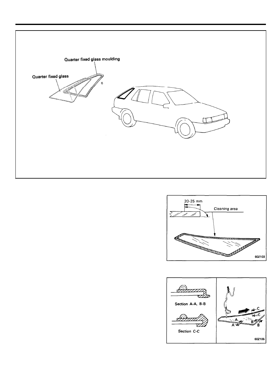
QUARTER FIXED GLASS
COMPONENTS
INSTALLATION
1. Clean the entire circumference of the glass with isopropyl
(rubbing) alcohol.
NOTE:
Do not proceed with the service procedure until they are
completely dry, and do not touch cleaned surface with
finger, dust, water, etc.
2. Apply the sealant to the entire circumference of the glass.
NOTE:
Install the glass to the body within five minutes.
6 0 - 3 8
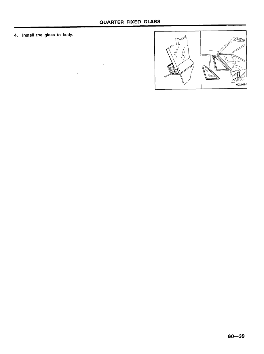
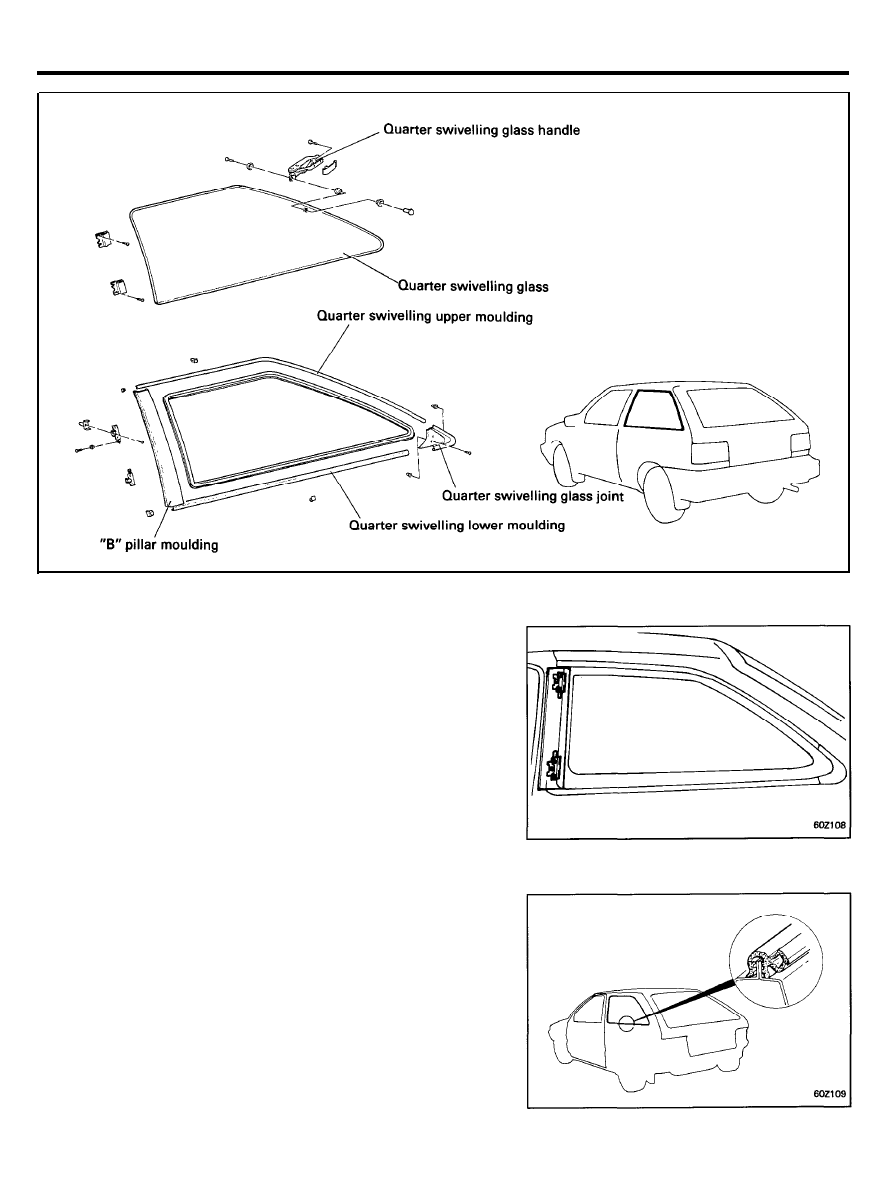
QUARTER SWIVELING GLASS
COMPONENTS
REMOVAL
1. Remove the “B” pillar moulding.
2. Remove the upper, lower and joint moulding.
6 0 - 4 0
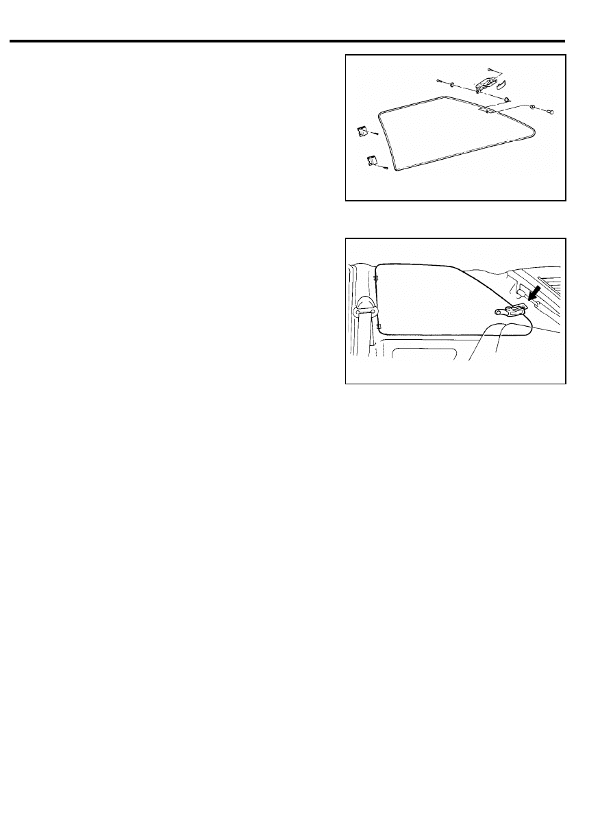
QUARTER SWIVELING GLASS
3. Remove the hinge mounting screws and the handle
mounting screws.
4. Remove the quarter swiveling glass.
INSTALLATION
1. Installation is the reverse of removal procedure.
6 0 - 4 1
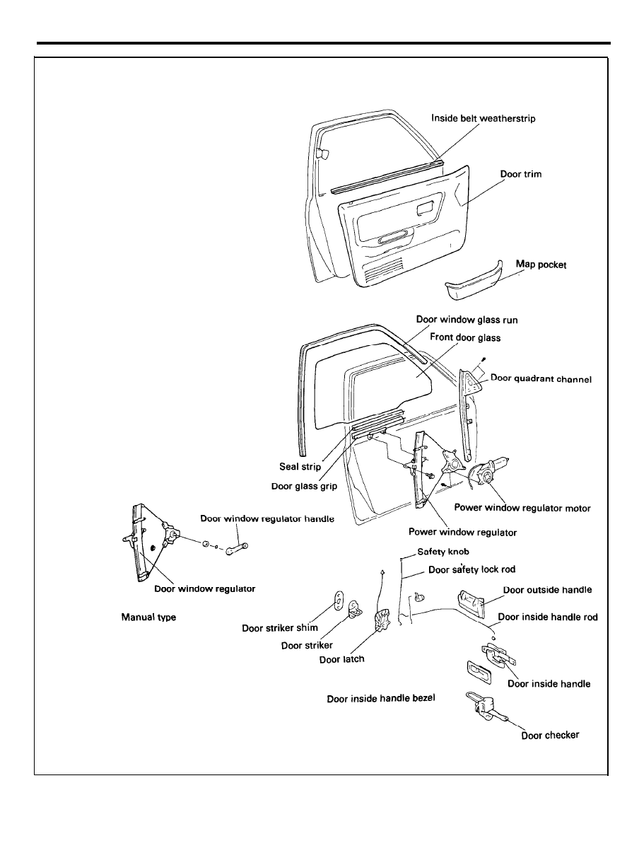
FRONT DOOR
COMPONENTS
6 0 - 4 2
FRONT DOOR
DOOR POSITION ADJUSTMENT
Check for flush fit with the body, then check for equal gap
between the front and rear, top and bottom door edges and the
body.
The door and body edges should also be parallel. Adjust at the
hinge with the Special Tool.
CAUTION
Attach protective tape to the fender edges near the place
where the hinge is installed.
DOOR STRIKER ADJUSTMENT
Make sure the door is not loose, and latches securely without
slamming. If it needs adjustment;
1. Draw a line around the striker plate for reference.
2.
Loosen the striker screws, and move the striker IN or OUT
to make the latch fit tighter or looser. Move the striker UP
or DOWN to align it with the latch opening. Then lightly
tighten the screws and recheck.
NOTE
Hold the outside handle out and push the door against the
body to be sure the striker allows a flush fit.
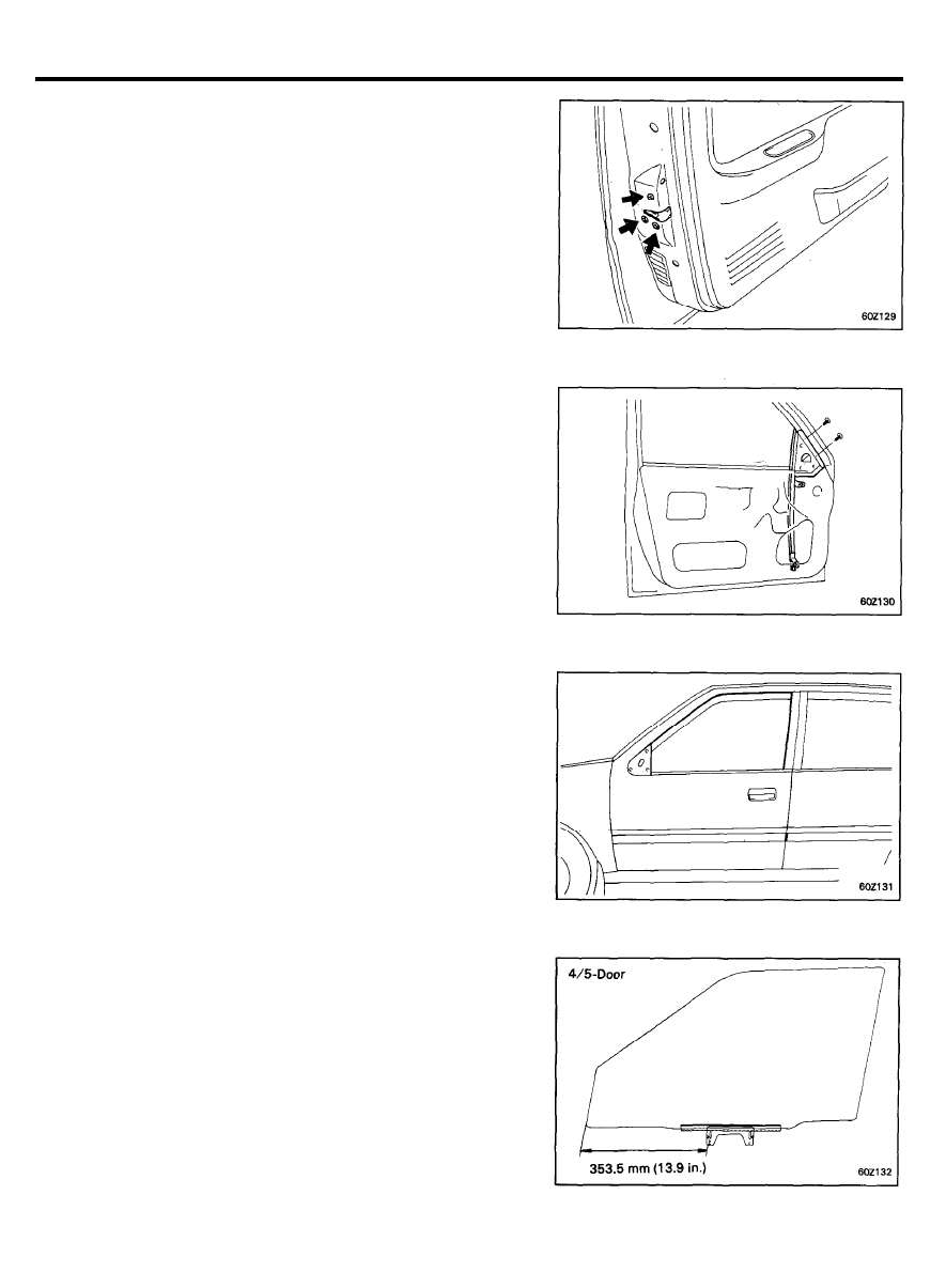
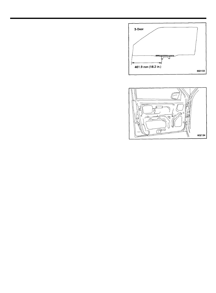
GLASS ADJUSTMENT
If the glass does not fit evenly when closed, adjust the slant of
the glass in the front-to-back direction.
INSIDE DOOR HANDLE ADJUSTMENT
Adjust the inside handle play by adjusting the mounting position
in the IN-to-OUT direction.
FULL STROKE [A]. . . . . . . . . . . . . . . . . . . . . . . . . . . . . . . . . . . . . . . 53°
6 0 - 4 3
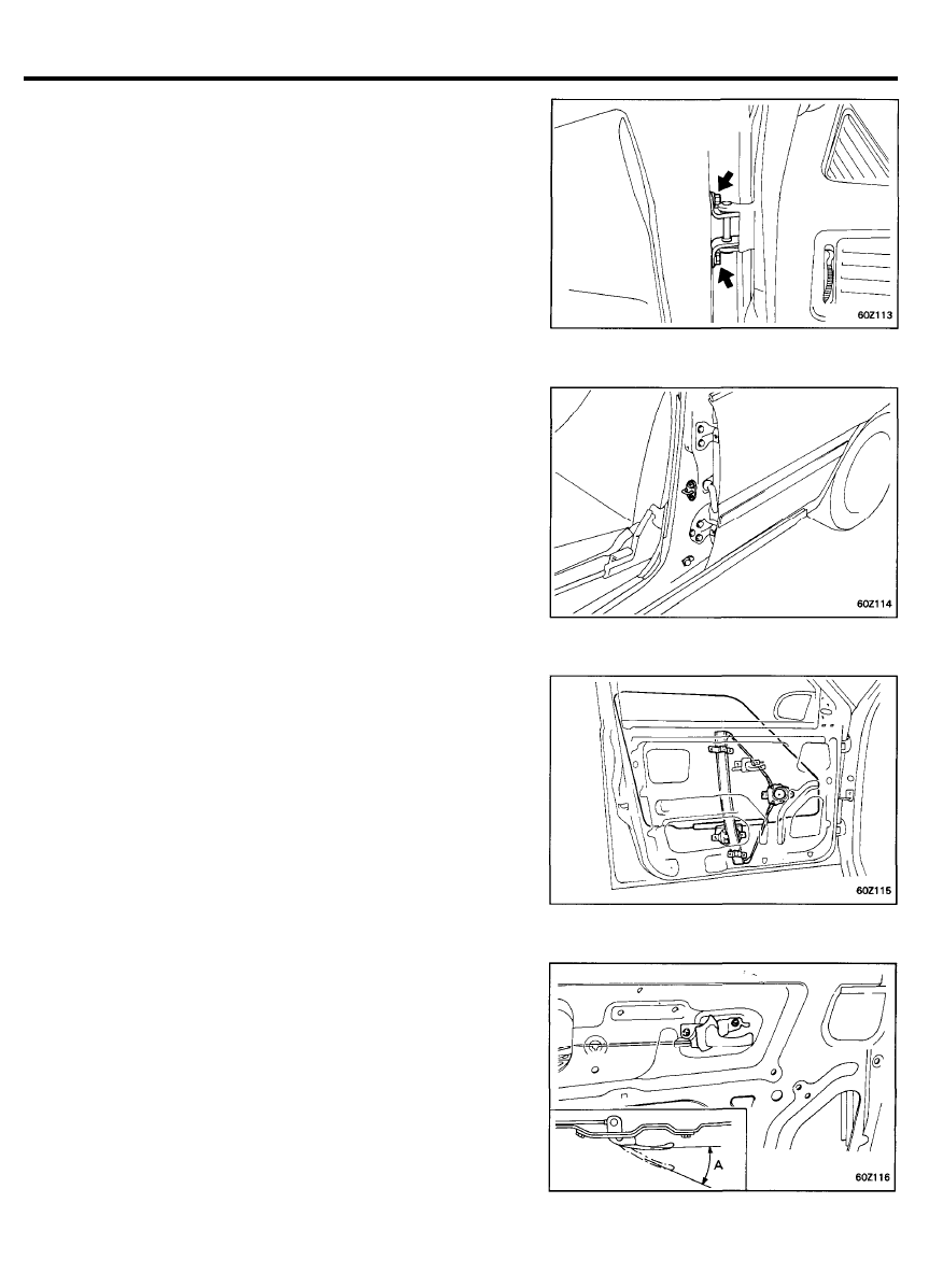
FRONT DOOR
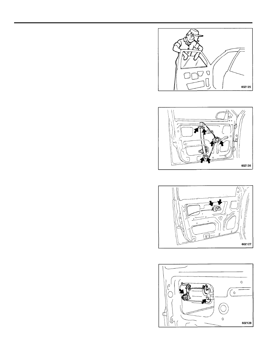
REMOVAL
1. Using a screwdriver,
remove the clip shown in the
illustration to remove the regulator handle. (Manual type
only)
2. Remove the quadrant inner cover.
3. Remove the rear view mirror mounting screws and then
remove the rear view mirror.
4. Remove the safety lock knob.
Remove the screws from the inside handle bezel and arm
rest.
5. Insert a screwdriver between the trim fasteners and door
panel to pry it loose.
Disconnect the connectors.
6 0 - 4 4
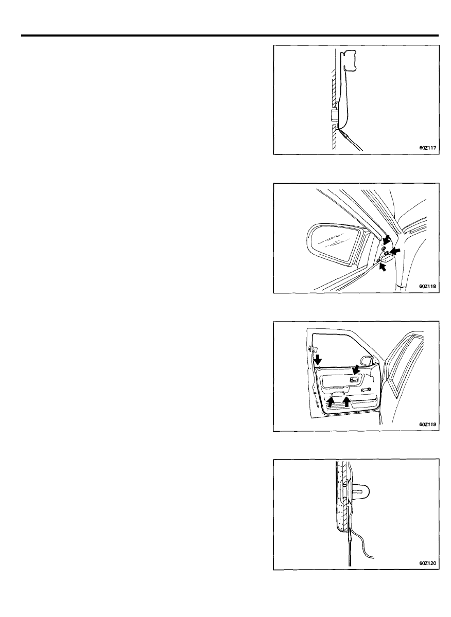
FRONT DOOR
6. Remove the door trim seal.
7.
Remove the front door frame rear moulding and the upper
moulding.
8. Remove the front door belt outside weatherstrip.
9. Remove the carrier plate bolts from the regulator channel.
6 0 - 4 5
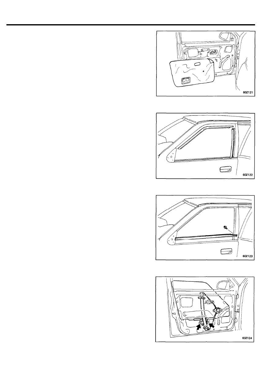
FRONT DOOR
10. Pull the door glass out through the window slot.
11. Remove the door regulator channel mounting bolts and then
remove the door regulator assembly.
12. Remove the inside handle mounting screws.
Turn the rod holding clip and then remove the rod from the
latch assembly.
13. Remove the outside door handle mounting bolts.
Disconnect the outside door handle rod from the outside door
handle at the position shown.
6 0 - 4 6
FRONT DOOR
14. Remove the door latch ‘and door lock actuator.
15. Remove the front door quadrant channel.
16. Remove the front door window glass run.
1. Installation is the reverse of removal procedure.
2.
If the door glass has been removed from the glass grip, be
sure to install it in the correct position.
INSTALLATION
6 0 - 4 7
FRONT DOOR
CAUTION
When installing the door trim seal, butyl tape should not be
placed over the door trim fastener mounting area.
6 0 - 4 8
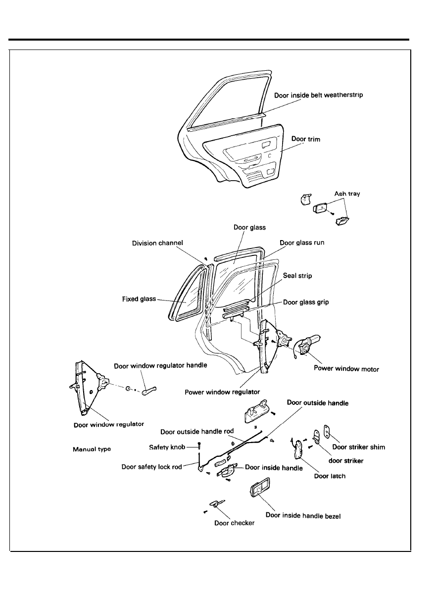
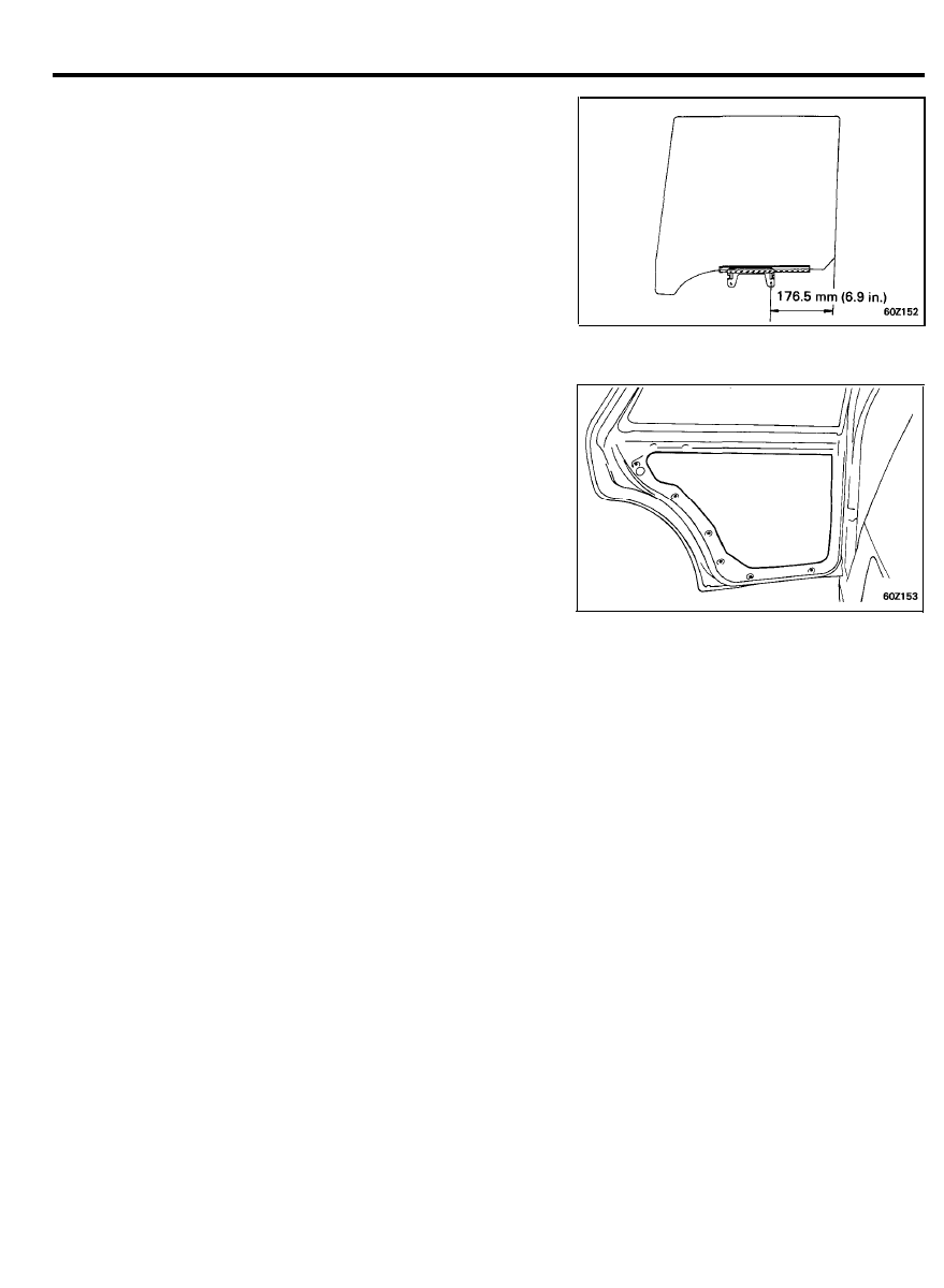
REAR DOOR
COMPONENTS
6 0 - 4 9
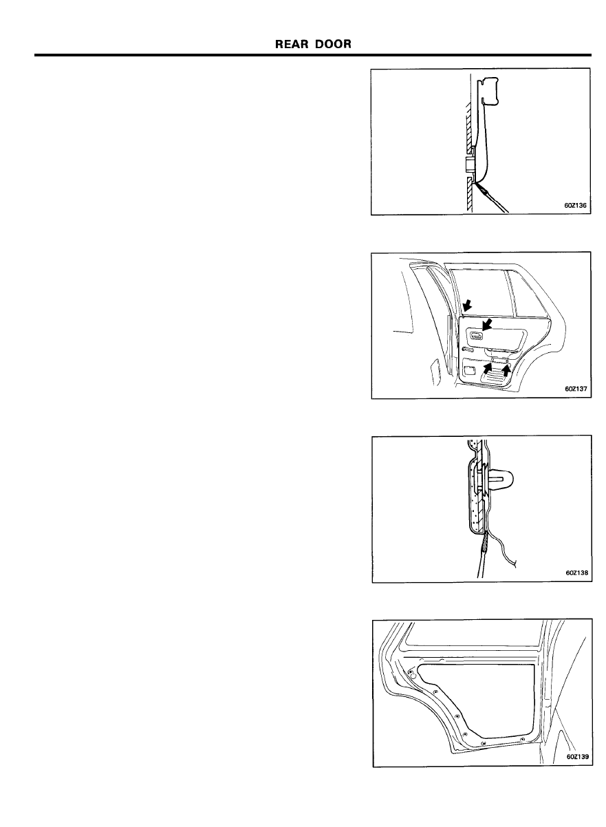
REMOVAL
1. Using a screwdriver,
remove the clip located in the
illustration to remove the regulator handle. Be careful to
avoid damaging the door trim panel. (Manual type only)
2. Remove the safety lock knob, inside handle bezel and arm
rest.
3.
Insert a screwdriver between the trim fasteners and the door
panel to pry it loose.
Disconnect the electrical connectors.
4. Remove the door trim seal.
6 0 - 5 0
REAR DOOR
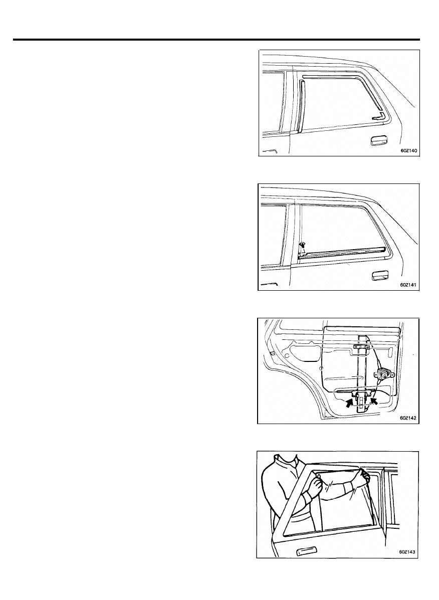
5.
Remove the rear door frame front moulding, upper moulding
and the rear door belt moulding joint.
6. Remove the rear door belt outside weatherstrip.
7.
Remove the carrier plate bolts from the regulator channel.
8. Remove the door glass.
6 0 - 5 1
REAR DOOR
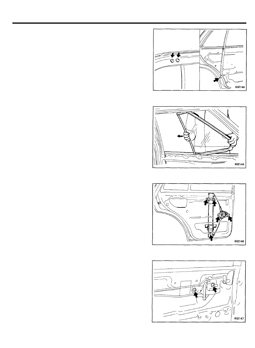
9. Remove the fixing screws and the bolts of the division
channel.
Remove the division channel.
10. Remove the fixed glass.
11. Remove the door regulator channel mounting bolts and then
remove the door regulator assembly.
12. Remove the inside handle mounting screws.
Turn the rod holding clip and then remove the rod from the
latch assembly.
6 0 - 5 2
REAR DOOR
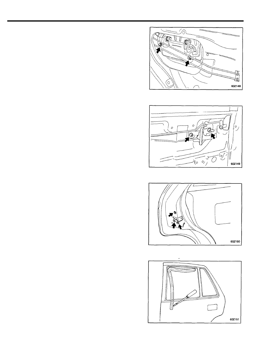
13. Remove the outside door handle mounting bolts.
Disconnect the outside door handle rod from the outside door
handle at the position shown.
14. Remove the safety lock rod mounting screw and then
remove the rod from the latch assembly.
15. Remove the door latch and door lock actuator.
16. Remove the rear window glass run.
6 0 - 5 3
REAR DOOR
INSTALLATION
1. Installation is the reverse of the removal procedure.
2.
If the door glass has been removed from the glass grip, be
sure to install it in the correct position.
CAUTION
When installing the door trim seal, butyl tape should not
be placed over the door trim fastener mounting area.
6 0 - 5 4
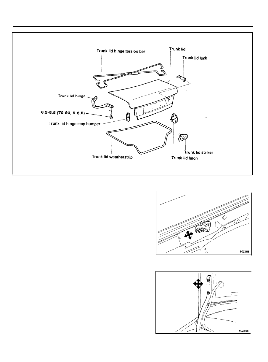
T R U N K L I D
COMPONENTS
TORQUE : Nm (kg.cm, Ib.ft)
ADJUSTMENT
1. Adjust the striker
up or down, and right or left until the trunk
lid is flush with the rear edge of the body.
2. Adjust the trunk hinges up or down and right or left as
necessary to equalizer the gap between the lid and body.
6 0 - 5 5
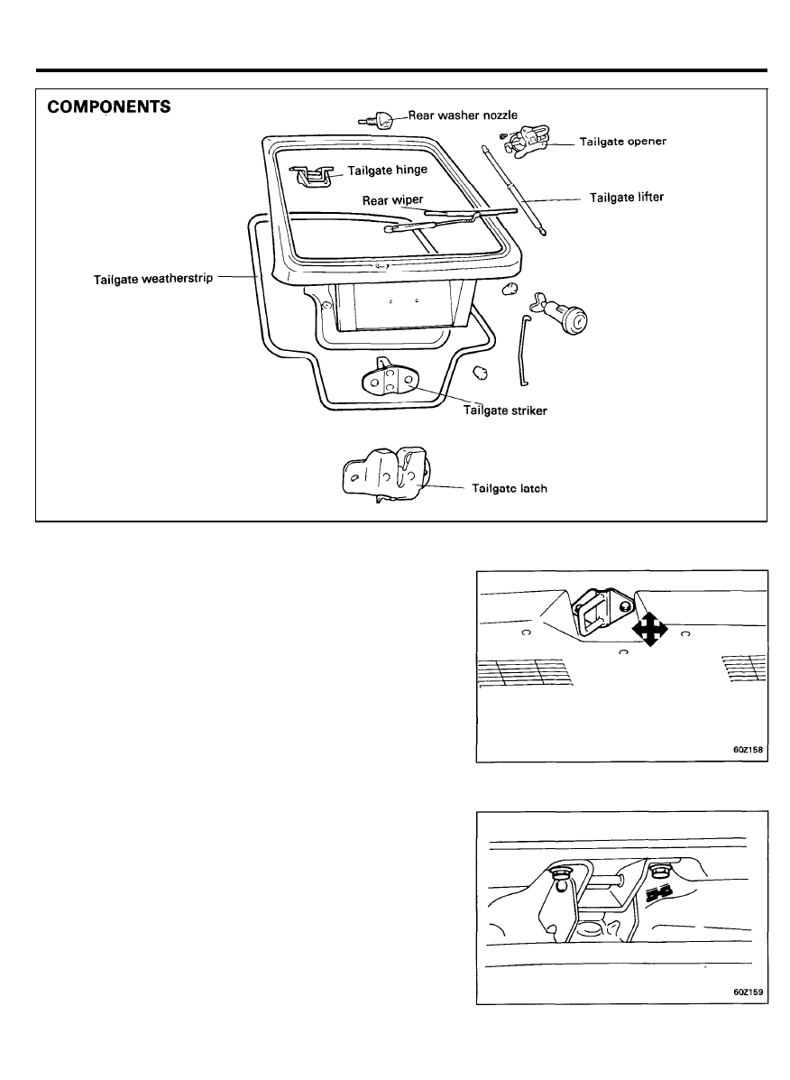
TAILGATE
ADJUSTMENT
1. Adjust the striker up or down, and right or left
tailgate is flush with the rear edge of the body.
until the
2. Adjust the tailgate hinges up or down and right or left as
necessary to equalizer the gap between the tailgate and
body.
6 0 - 5 6
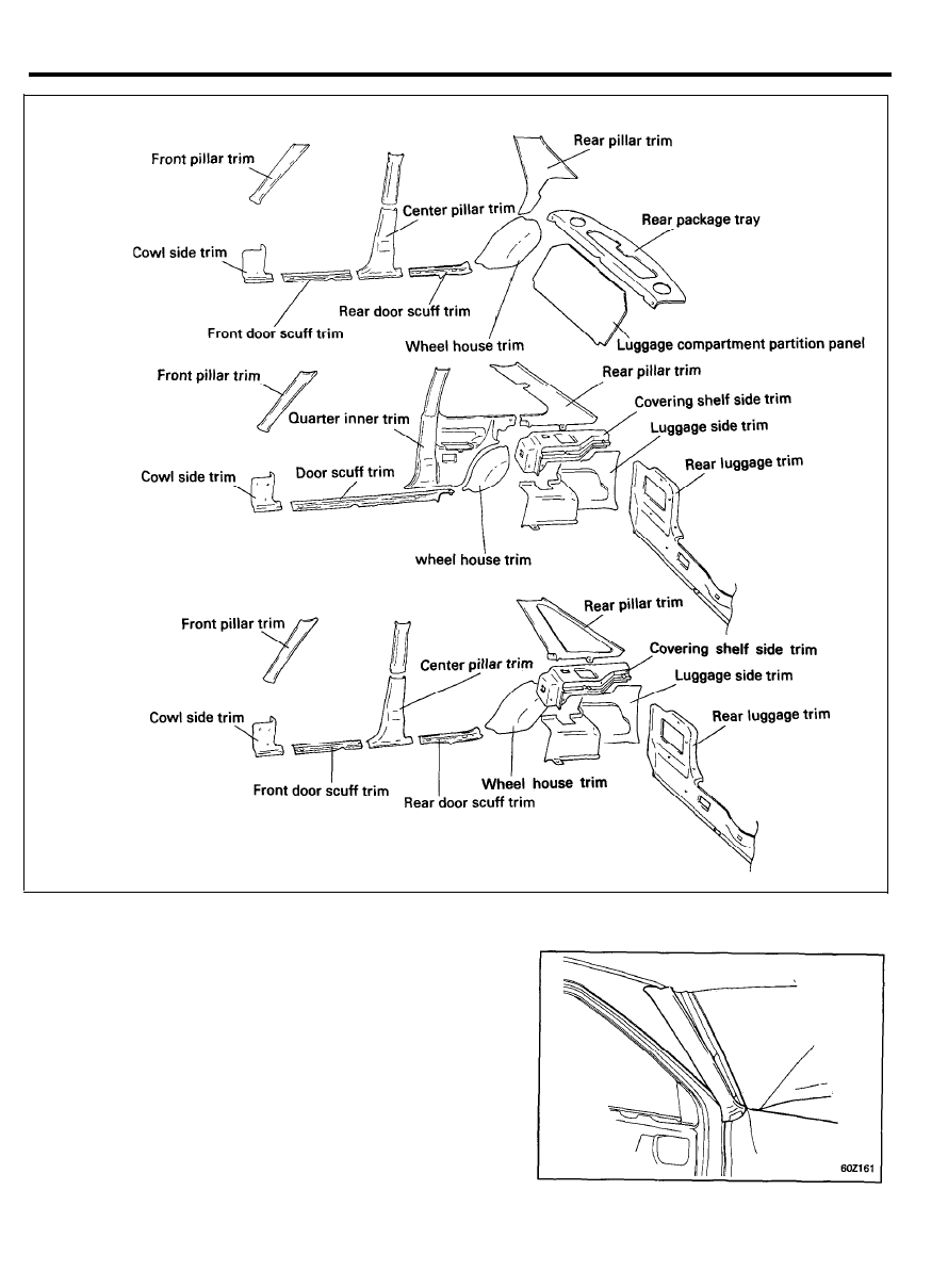
INTERIOR TRIM
COMPONENTS
REMOVAL
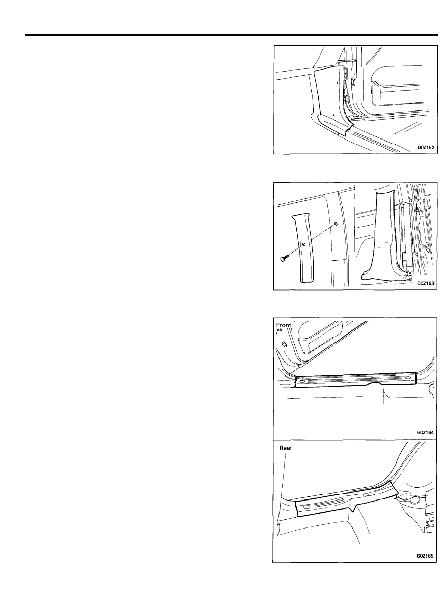
Front Pillar Trim
1. Remove the front pillar trim with a screwdriver.
6 0 - 5 7
INTERIOR TRIM
Cowl Side Trim
1. Remove the cowl side trim mounting screws, and then
remove the cowl side trim.
Center Pillar Trim
1. Remove the center pillar lower trim.
2. Remove the center pillar upper trim mounting screw, and
then remove the center pillar upper trim.
Door Scuff Trim (4-Door, 5-Door)
1. Remove the screws from the door scuff trim.
2. Remove the door scuff trim.
6 0 - 5 8
INTERIOR TRIM
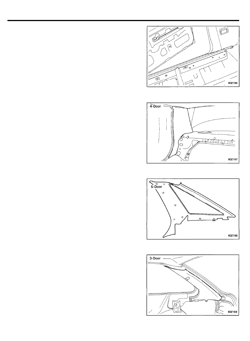
Door Scuff Trim (3-Door)
1. Remove the door scuff trim with a screwdriver.
Rear Pillar Trim
1. Remove the bolt from the rear seat belt lower anchor.
2. Using a screwdriver, remove the rear pillar trim.
6 0 - 5 9
INTERIOR TRIM
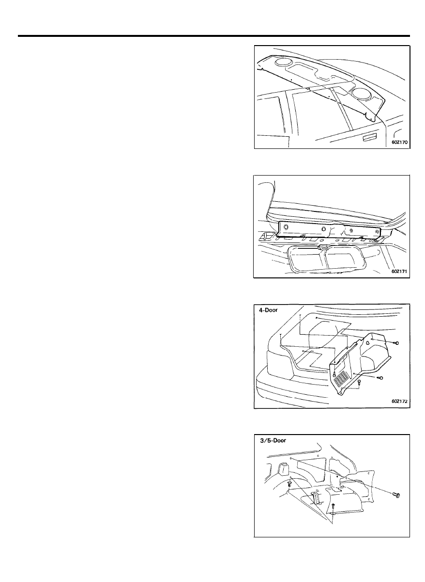
Rear Package Tray Trim
1.
Remove the rear package tray trim mounting plugs and the
rear package tray trim.
Rear Transverse Trim
1.
Remove the transverse trim mounting fasteners and the rear
transverse trim.
Luggage Side Trim
1. Remove the screws and plugs from the luggage side trim.
6 0 - 6 0
INTERIOR TRIM
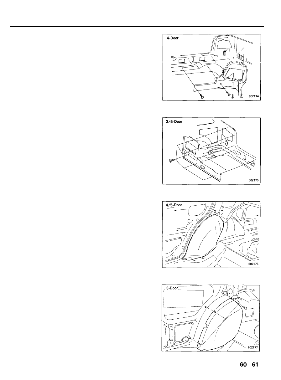
Luggage Rear Trim
1. Remove the luggage rear trim.
Wheel House Trim
1. Remove the rear seat cushion.
2. Remove the covering shelf side trim and the luggage side
trim.
3. Remove the wheel house trim with a screwdriver.

INTERIOR TRIM
Luggage Compartment Partition Panel (4-Door)
1. Remove the rear seat.
2. Remove the luggage compartment partition panel.
Quarter Inner Trim (3-Door)
1. Remove the door scuff trim.
2. Remove the cover shelf side trim.
3. Remove the quarter inner trim.
6 0 - 6 2
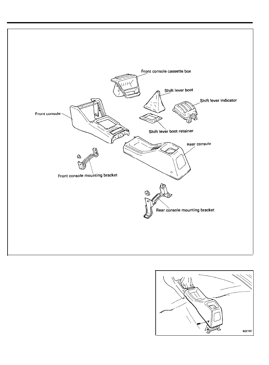
CONSOLE
COMPONENTS
REMOVAL
1.
Remove the rear console mounting screws and then pull out
the rear console.
6 0 - 6 3
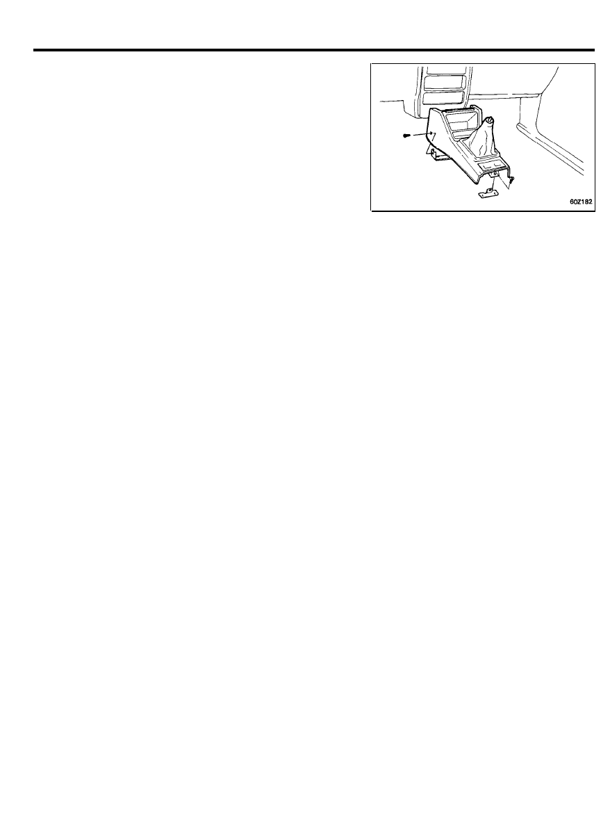
CONSOLE
2. Remove the transaxle control lever.
3.
Remove the front console assembly and then disconnect the
connectors.
6 0 - 6 4
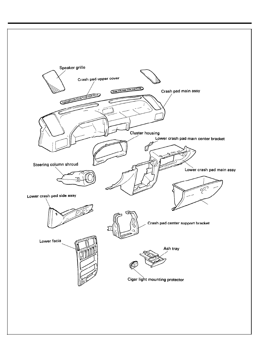
CRASH PAD
COMPONENTS
6 0 - 6 5
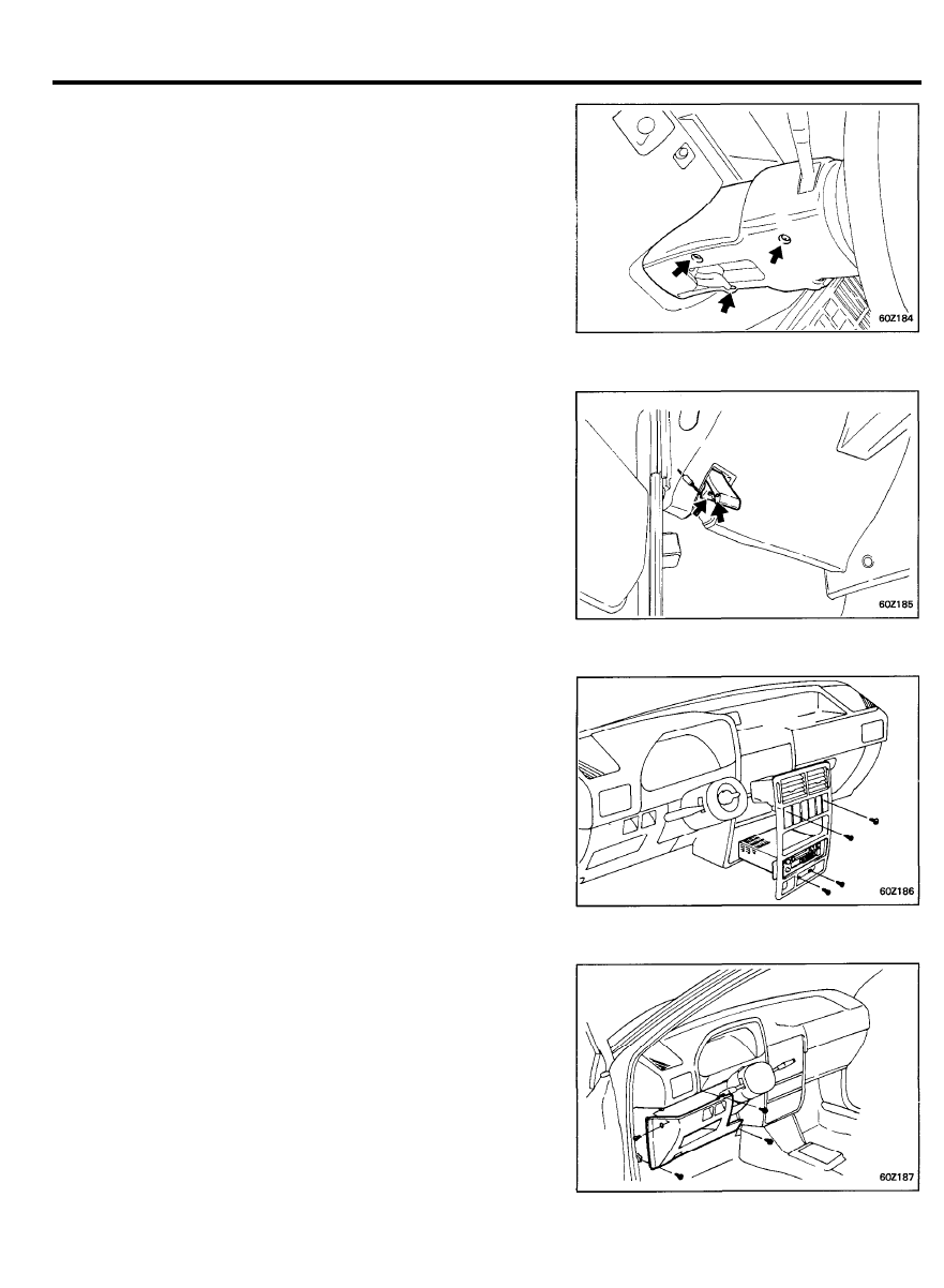
CRASH PAD
REMOVAL
1. Remove the steering wheel.
2. Remove the steering column lower and upper shroud.
3. Remove the hood release handle mounting screws.
4. Remove the lower facia panel.
5. Remove the side lower crash pad.
6 0 - 6 6
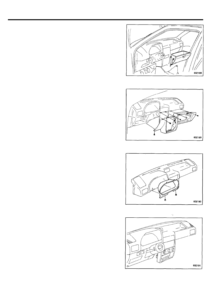
CRASH PAD
6. Remove the glove box.
7. Remove the main lower crash pad.
8.
Remove the cluster assembly and disconnect the connectors.
9. Remove the radio and disconnect the connectors.
6 0 - 6 7
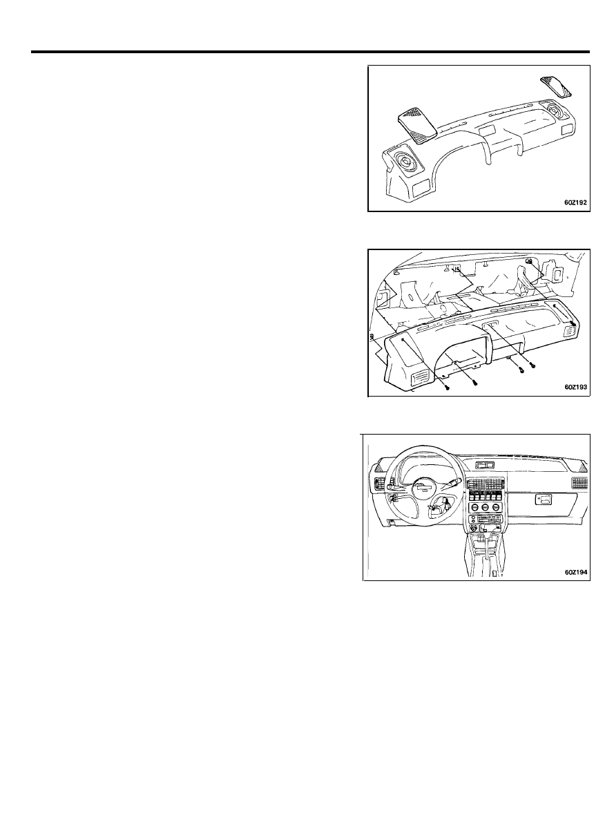
CRASH PAD
10. Detach the front speaker grille from the main crash pad.
11. Remove the front speaker.
12. Remove the main crash pad.
INSTALLATION
1. Installation is the reverse of the removal procedure.
2. Connect all of the connectors securely.
6 0 - 6 8
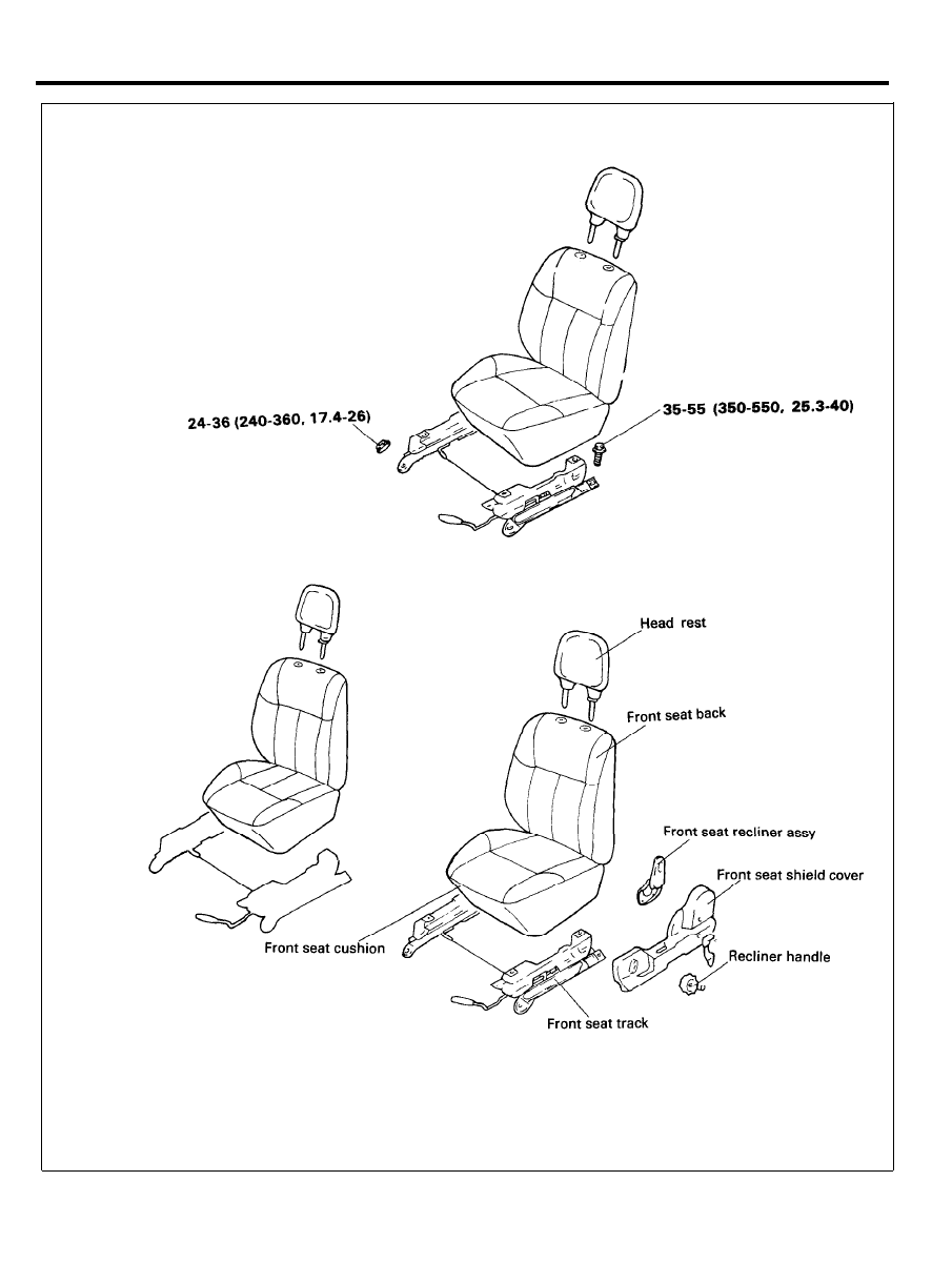
FRONT SEAT
COMPONENTS
TORQUE : Nm (kg.cm, Ib.ft)
6 0 - 6 9
FRONT SEAT
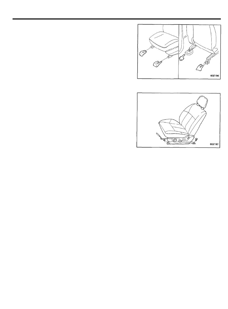
REMOVAL
1. Pull out the front seat mounting cover.
2. Remove the front seat assembly.
6 0 - 7 0
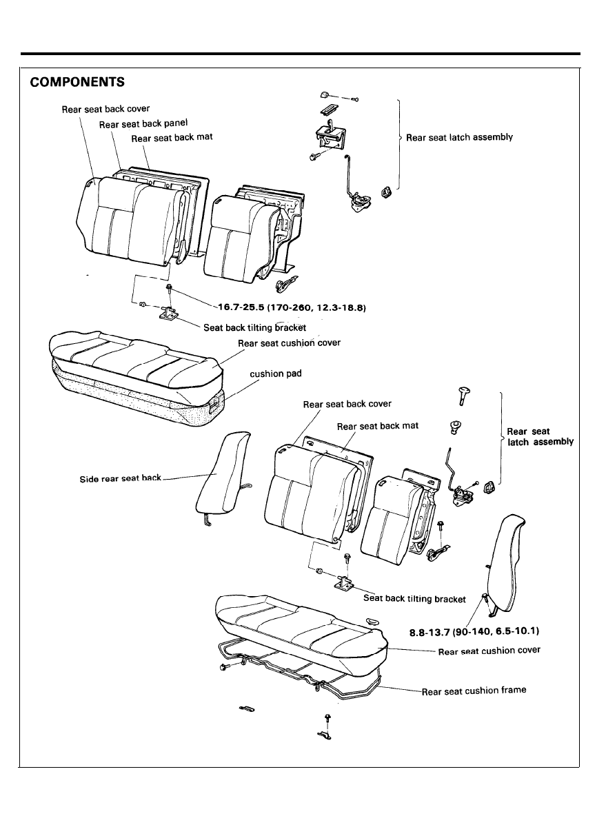
REAR SEAT
TORQUE : Nm (kg.cm, Ib.ft)
6 0 - 7 1
REAR SEAT
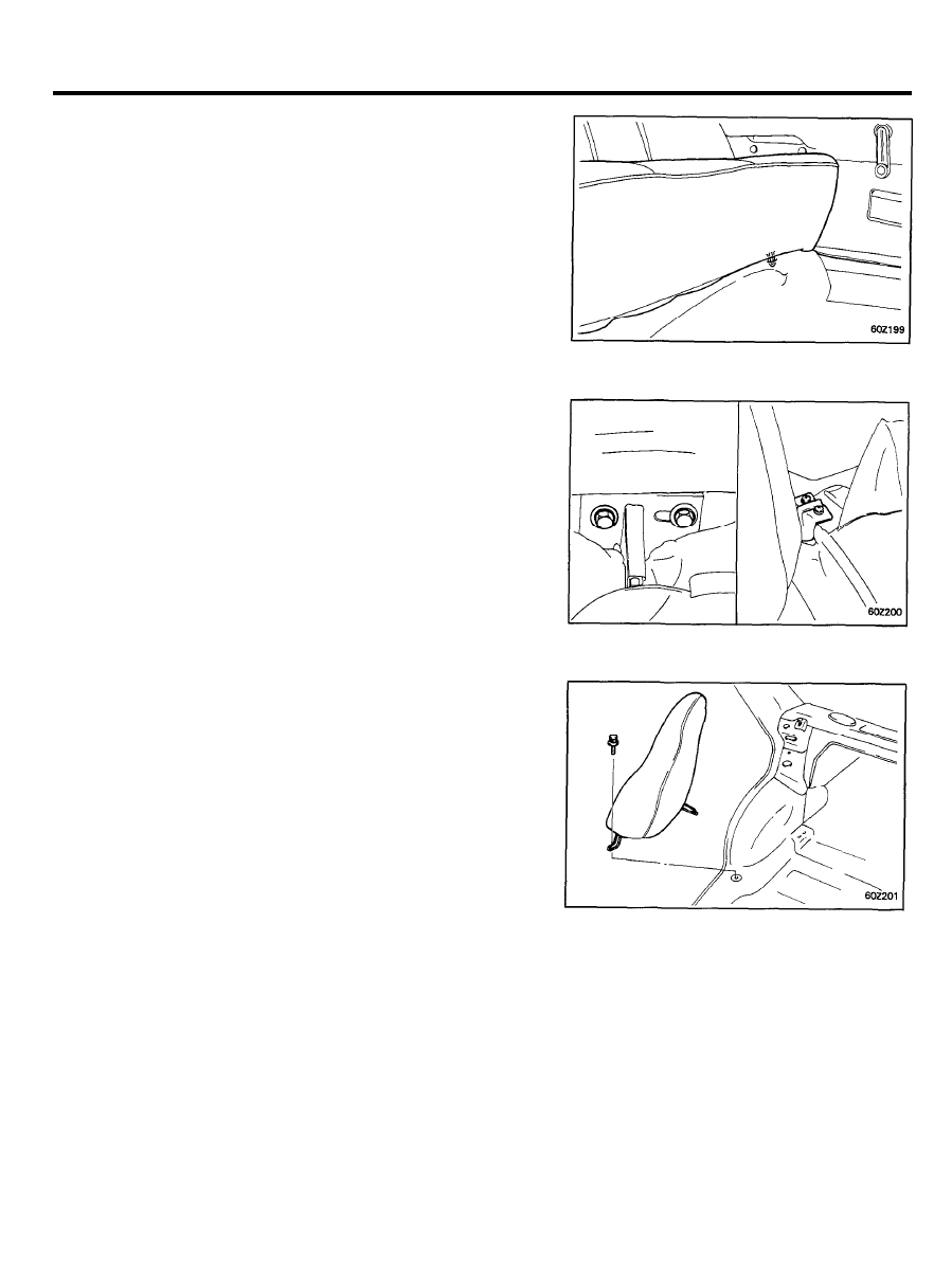
REMOVAL
1. Pull out the rear seat cushion holder.
2. Remove the rear seat cushion.
3.
Remove the rear seat back mounting bolts and remove the
rear seat back mat.
4. Remove the side rear seat back.
INSTALLATION
1. Installation is the reverse of removal procedure.
6 0 - 7 2
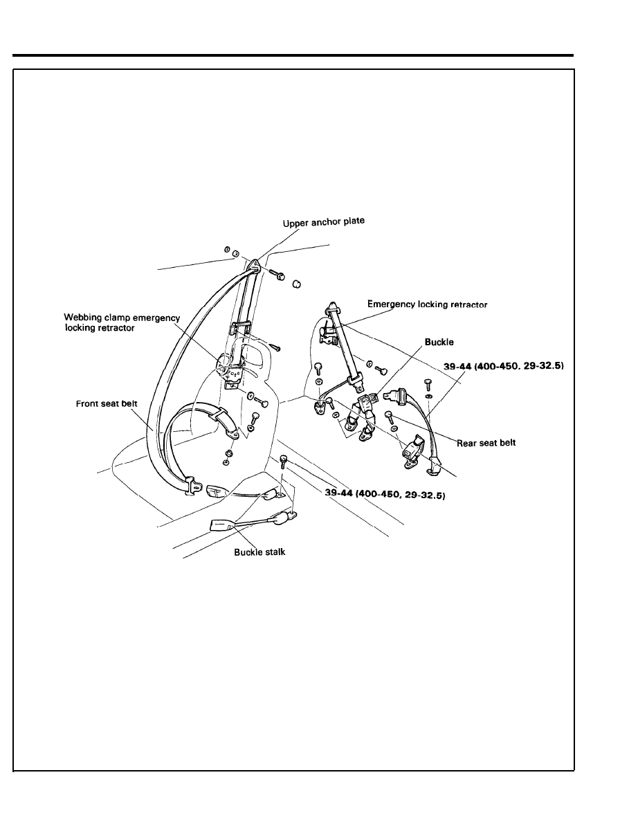
SEAT BELT
COMPONENTS
TORQUE : Nm (kg.cm, Ib.ft)
6 0 - 7 3
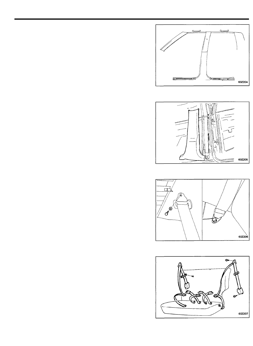
SEAT BELT
REMOVAL
Front Seat Belt
1. Remove the door scuff trim.
2. Remove the upper anchor plate and the lower plate.
3. Remove the center pillar trim.
4. Remove the front seat belt assembly.
Rear Seat Belt
1. Remove the rear seat assembly.
2. Remove the rear pillar trim.
3. Remove the rear seat belt assembly.
6 0 - 7 4
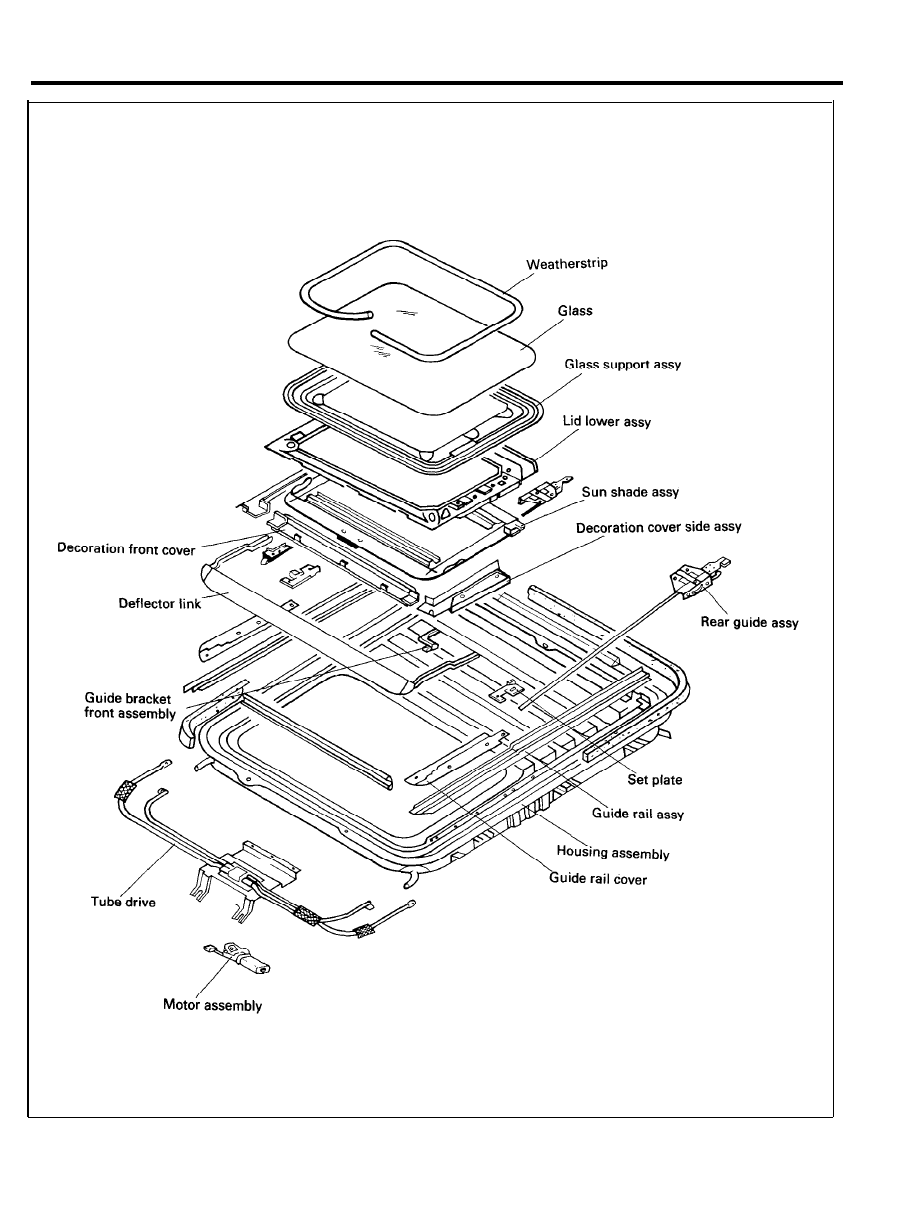
COMPONENTS
SUNROOF
6 0 - 7 5
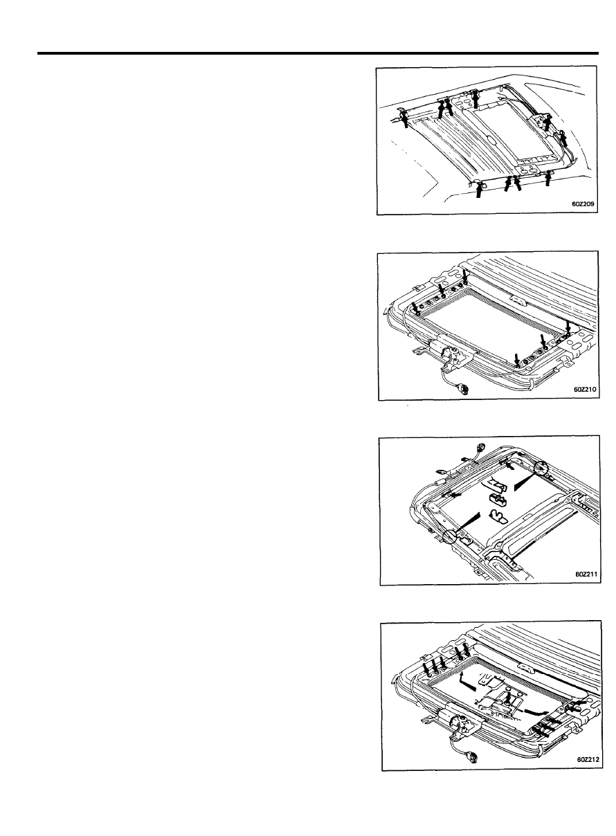
SUNROOF
REMOVAL
1. Remove the headlining.
2. Remove the sunroof assembly.
3. Remove the decoration cover and the glass panel.
4. Fully open the lid lower panel.
5. Remove the deflector assembly.
6. Completely close the lid lower panel and remove the lid
lower panel.
6 0 - 7 6
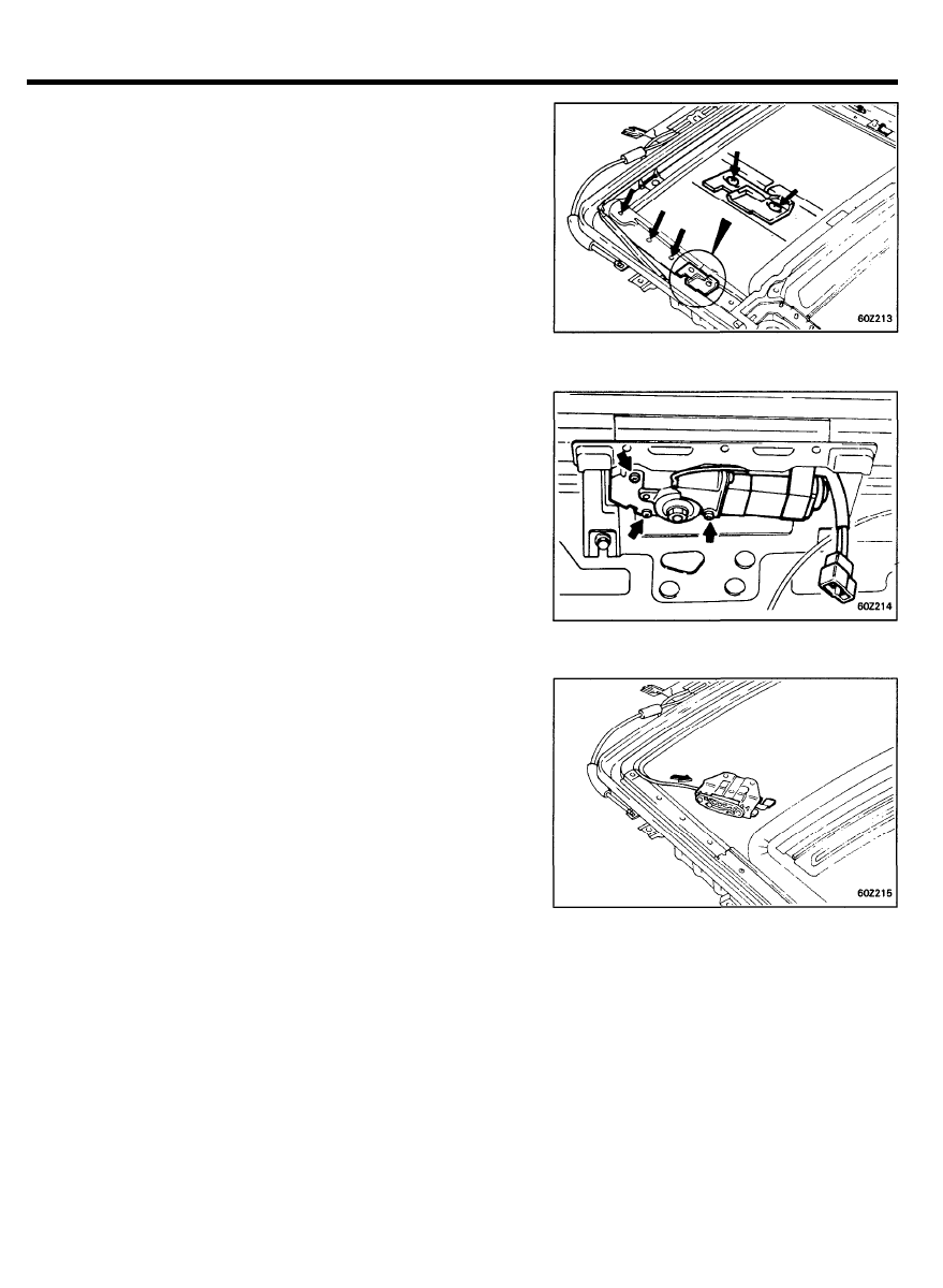
SUNROOF
7. Remove the guide rail cover and stopper.
8. Remove the motor assembly.
NOTE
There are two types of mounting screws, long and short.
Be sure to install them in the correct position.
9. Push out the driving cable.
INSTALLATION
1. Installation is the reverse of the removal procedure.
6 0 - 7 7
SUNROOF
Check Operating condition after installation.
1. If the panel movement is hard, check and adjust.
1) Make sure the battery voltage is normal.
2)
Make sure that the sunroof sliding unit is free of foreign
material.
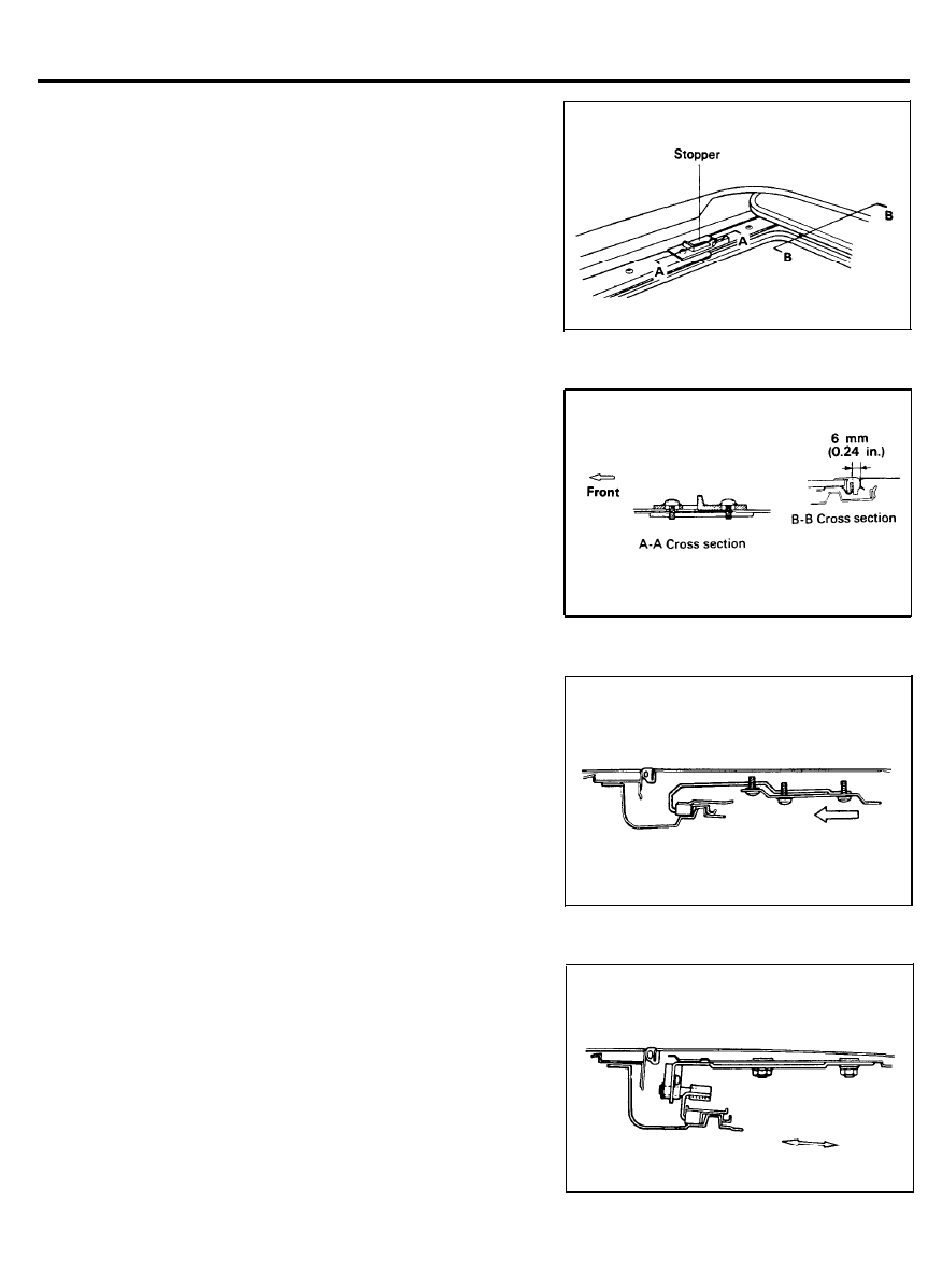
3) Make sure that, when the glass panel opens, the rear
position of the panel does not interfere with the roof
panel. If interference occurs, fully open the glass panel
and move the stopper forward.
NOTE
If the stopper is moved forward too far, it may cause
malfunction or leaks. Make sure the gap between the glass
panel and roof panel is not more then 5 mm (0.2 in.).
4)
Position adjustment of guide front brackets to guide rails.
Move both of them, left and right, about 1 mm (0.04 in.)
outward.
5)
Position adjustment of guide rear brackets to guide rails.
Move both of them, left and right, about 1 mm (0.04 in.)
outward or inward.
6 0 - 7 8
SUNROOF
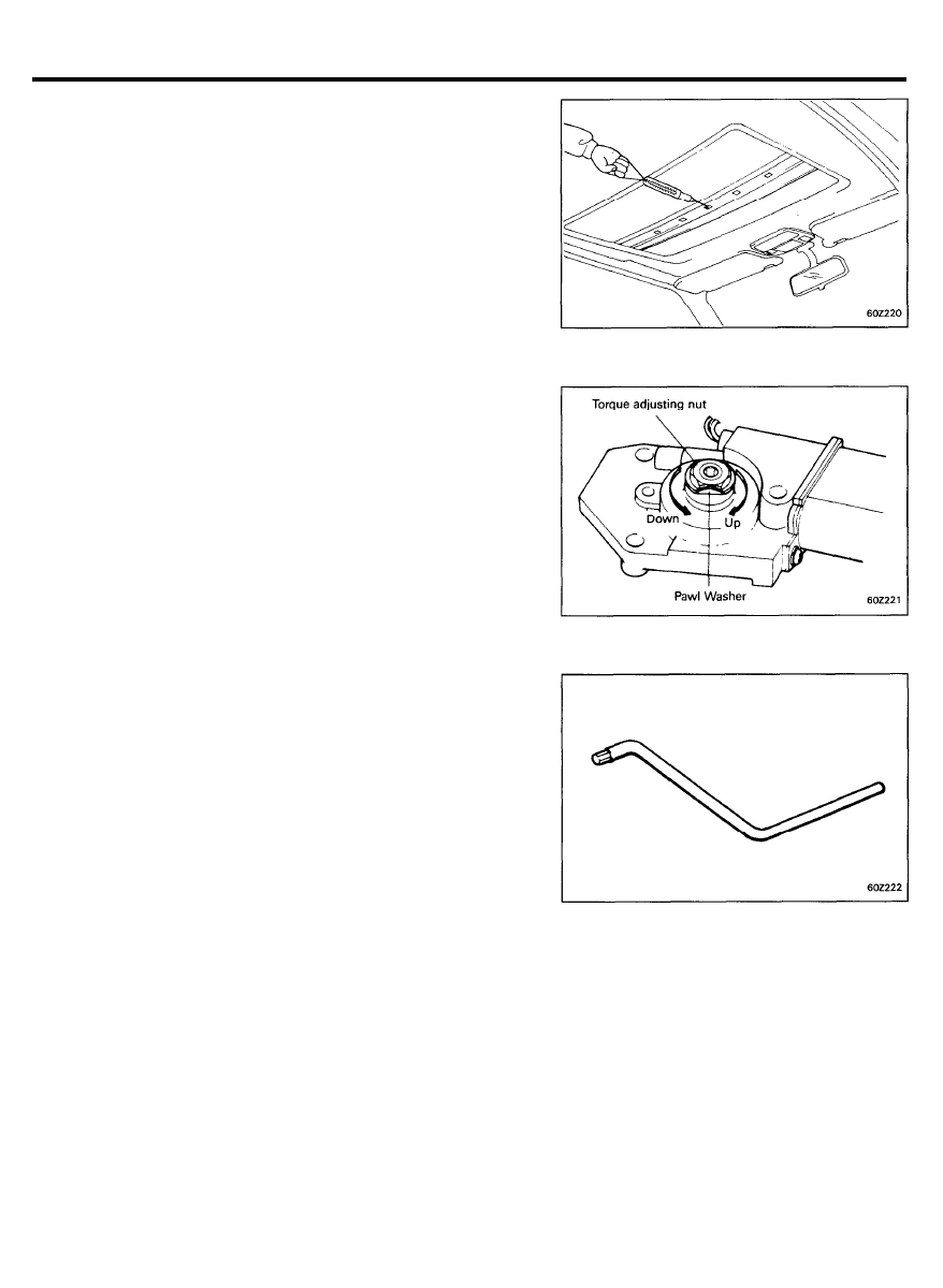
6)
Measure the driving force of the motor, and adjust it to
20-25 kg (44.1-55.7 lb) with the torque adjustment
nut on the motor.
7) To measure, use the deep hole in the center of the lid
lower panel.
8) After adjustment, be sure to lock the nut with the pawl
washer.
NOTE
If the sunroof could not be electrically operated.
1) Remove the plastic cover.
2) Insert the wrench into the Motor Socket.
3) Turn the wrench clockwise (open) and counter clock
wise. (close)
6 0 - 7 9
SUNROOF
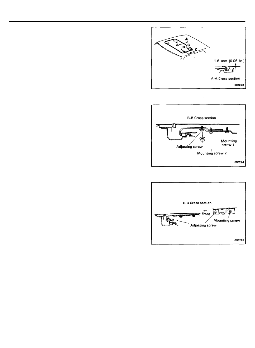
Adjustment
1. Adjust the height of the glass panel.
(A-A cross section)
Adjust the difference in height between the glass panel and
the roof panel to no more than 1.5 mm (0.06 in.)
(Procedures to adjust 8-8 cross section)
1) Loosen mounting screws 1 and 2.
When adjusting no more than 2 mm (0.08 in.), it may
be better not to move screw 1.
2) Adjust by turning the adjust screw,
Clockwise . . . . . . . . . . . . . . . . . . . . . . . . . . . . . . . . . . . . . . . . Up
Counterclockwise . . . . . . . . . . . . . . . . . . . . . . . . . . . . . . Down
3) Tighten mounting screws 1 and 2.
(Procedures to adjust C-C cross section)
1) Loosen the mounting and adjusting screws. For easy
adjustment, do not loosen the mounting screws to much.
2)
Adjust by moving the glass panel from inside or outside.
3)
Tighten the adjusting screw and the mounting screws in
that order.
6 0 - 8 0
PASSIVE SEAT BELT
COMPONENTS
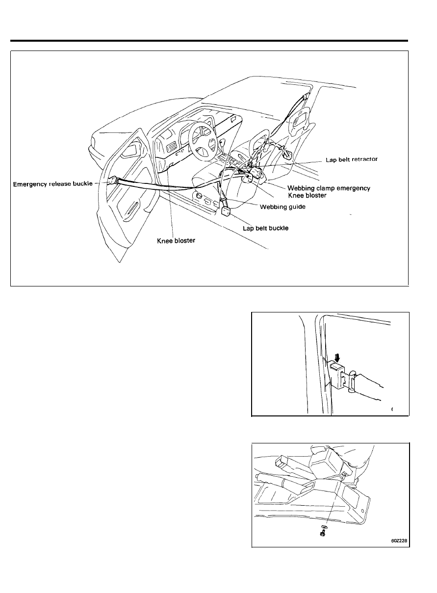
REMOVAL
Passive Seat Belt
1.
Remove the buckle side belt and switch assembly from the
front door trim.
2. Remove the passive seat belt retractor from the seat belt
mounting bracket.
6 0 - 8 1
PASSIVE SEAT BELT
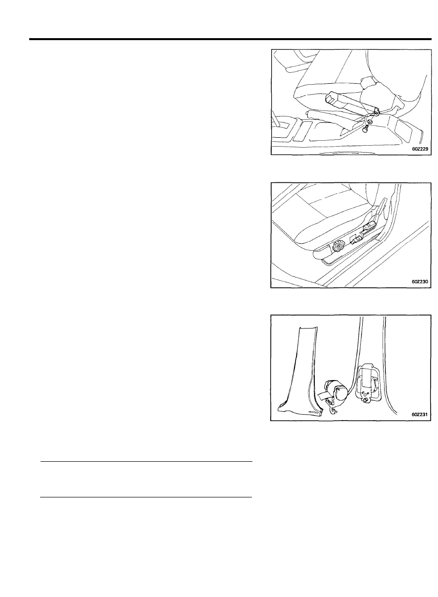
Lap Belt
1. Remove the buckle assembly as shown in Figure.
2. Remove the webbing guide from the seat shield cover.
3. Remove the retractor assembly from the mounting bracket
as follows.
1) Pull out the weather strip by hand.
2) Remove the center pillar trim.
3) Remove the bolt combining the retractor and the
mounting bracket.
4) Pull the located pin from the mounting bracket.
CAUTION
Installing the retractors, the mounting angle is 15°C in the
passive seat belt; vertical in the lap belt.
Installation
1. Install can be carried out in the reverse order of removal.
Torque (anchor bolt)
Nm (kg.cm, Ib.ft)
Passive seat belt . . . . . . . 3 9 - 4 4 ( 4 0 0 - 4 5 0 , 2 8 . 9 - 3 2 . 5 )
Lap belt . . . . . . . . . . . . . . . . 3 9 - 4 4 ( 4 0 0 - 4 5 0 , 2 8 . 9 - 3 2 . 5 )
6 0 - 8 2
Wyszukiwarka
Podobne podstrony:
FM 20 3 Camouflage, Concealment, and Decoys
Food processing technology 3rd edition (P J Fellows) 20 Dielectric, ohmic and infrared heating
The Lucidity Institute Out Of Body Experiences And Lucid Dreams
body piercings and tattoos
20 Fame pros and cons
EXTERIOR AND INTERIOR TRIM
76 Exterior and Interior Trim
76 Exterior and Interior Trim
EXTERIOR AND INTERIOR TRIM
21 ch 20(406 421) METABOLISM, NUTRITION, AND BODY TEMPERATURE
Kundalini Is it Metal in the Meridians and Body by TM Molian (2011)
CCI Job Interview Workbook 20 w PassItOn and Not For Group Use
body parts dobble head and shoulders
więcej podobnych podstron