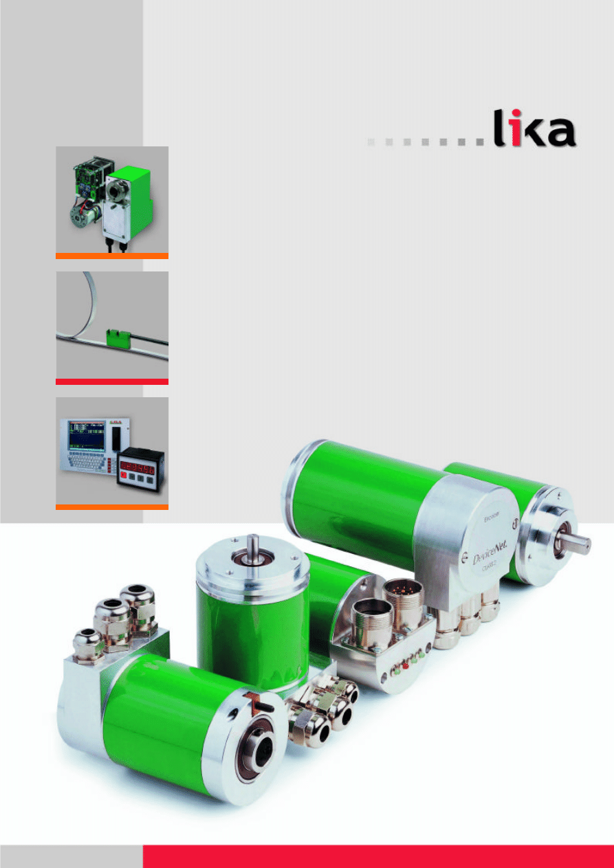
Absolute and Incremental Encoders
THE MOVEMENT OF AUTOMATION
Lika Electronic develops successfully innovative and
effective solutions to automation since 1982. In the
new and enlarged headquarter in Carrè (VI) works a
staff of about 50 people made up of technicians, engi-
neers and employees to design and manufacture
absolute and incremental encoders for the measure-
ment of linear and angular movement.
MOVEMENT IS THE MECHANISM
Lika Electronic is the Italian leader in the field of:
• production of rotative and linear position encoders
• production of axis controls and positioning
systems
• analogue and digital electronic design
• mechanical design of parts and systems
MOVEMENT IS EXECUTION RAPIDITY
Our target is to meet the customers’ requirements in the
shortest time. Our technical staff is able to carry out
rapidly all procedures, from the recognition of the
customers’ requirements to the final inspection.
MOVEMENT IS A PLAY OF CONTINUOUS MOVING
We have chosen to focus the attention on products pur-
posely studied for the customer, which place perfor-
mance and multi-functonality before serialization and
volume. Lika’s commitment is to accept but also to issue
the most exciting challenges to its customers, offering
the following array of services:
• systems analysis and feasibility studies
• systems design and plan development with the
supplying of technical, mechanical and software
documentation in accordance with a regular or an
arranged standard
• training courses for the use and maintenance of the
produced systems/equipment
• supplying of spare parts
•assistance for qualifications and type-approval of
equipment and components
MOVEMENT IS INNOVATION
Innovation and research are our pride. It’s our custom to
cooperate with the most prestigious Italian Universities,
like those of Padua, Pavia and Trieste and with the most
accredited Institutes for research, with which we work
out plans and establish permanent links.
MOVEMENT IS GOING FAR
After many applications in the military field, in the presen-
ce of vacuum and radiation, we are actively part of an
international project in the
space sector and we have
established a profitable col-
laboration with the CISAS
(Interdepartmental Centre
of Space Studies and
Activities) at the University
of Padua.
Lika is actually one of the
few companies in the world
able to produce ESA certi-
fied encoders for the space.
An incremental encoder will be employed in the mecha-
nism of the WAC and NAC telescopes forming the OSIRIS
payload in the
ROSETTA-ESA mis-
sion. Our encoders
are more accurate
and lighter, they
absorb less power
and are able to work
at wide ranges of
temperature. The
most interesting
applications in the
space sector are:
• the angle measure in laying systems (telescopes), com-
munication links among satellites
• the introduction of integrated measurement systems in
trim sensors (sun, horizon)
• the angle measurement of various mechanisms like fil-
ter cases, photographic shutters etc.
• the angle measurement within the action of robots
MOVEMENT IS A QUALITATIVE LEAP
Our whole production of Lika is certified by a SIT centre and
product samples are periodically tested by qualified centres.
We apply the following standard procedure on every com-
ponent:
• quality control of parts delivered by our suppliers
• conformity inspection and control during the production
process
• control of the automatic assembly line
• final inspection
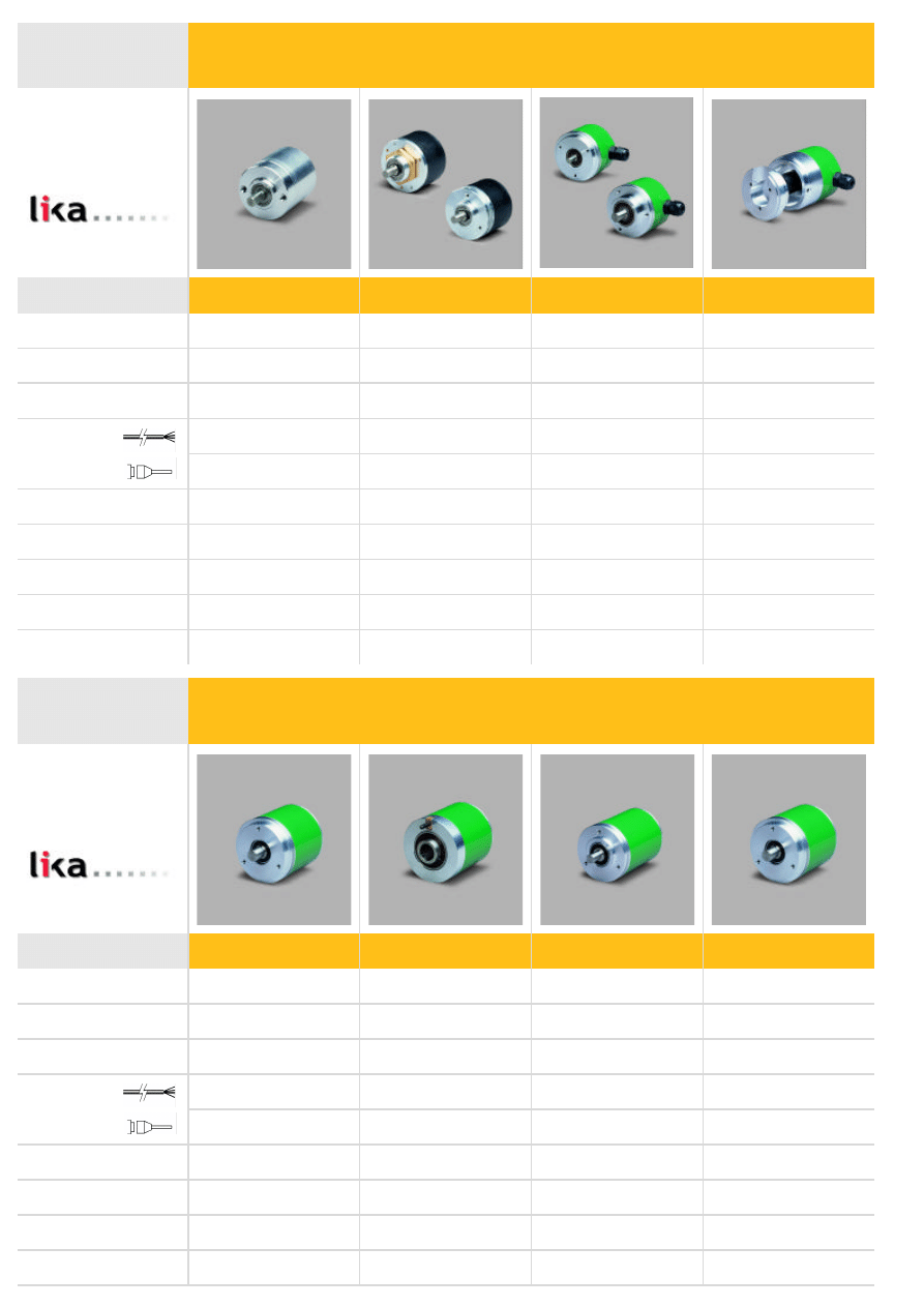
Series
I28
28
4, 5
•
1024 max.
100 max.
NPN, PNP, Push-Pull,
Line Driver
-20 °C +70 °C
IP54
I40, I41
40
standard size
4, 6, 6.35, 8
•
3600 max.
100 max.
Push-Pull, Line Driver
-20 °C +70 °C
IP54
I58, I58S
58
6, 8, 9.52, 10, 12
•
•
10000 max.
300 max.
Push-Pull, Line Driver, 1 Vpp
-40 °C +100 °C max.
IP65 max.
I58C
58
6, 8, 10, 12
•
•
10000 max.
300 max.
Push-Pull, Line Driver
-40 °C +100 °C max.
IP65 max.
AS58, AS58S,
AM58, AM58S
58
standard size
6, 8, 9.52, 10, 12
•
•
17 bit, 17x12 bit max.
Push-Pull, SSI, NPN, PNP
-40 °C +100 °C max.
IP65
ASC58, AMC58
58
14, 15
•
•
17 bit, 17x12 bit max.
Push-Pull, SSI, NPN, PNP
-40 °C +100 °C max.
IP65
AS5, AM5
50
6, 8, 9.52, 10, 12
•
11 bit, 11x8 bit max.
Push-Pull, SSI, NPN, PNP
-40 °C +100 °C max.
IP65
Features
Housing (mm)
Shaft ø (mm)
Connections
Resolution
Output freq. (kHz)
Output
Operating temperature
Protection
Series
Features
Housing (mm)
Shaft ø (mm)
Connections
Resolution
Output
Operating temperature
Protection
ROTAPULS incremental encoders
ROTACOD absolute encoders
ASR58
Programmable
cam encoder
58
6, 8, 9.52, 10, 12
•
3600/0,1°
16 x Push-Pull, 100 mA
-20°C + 70 °C
IP65
small size
Seies
I65, IT65
65
standard size
6, 8, 9.52, 10, 12
•
•
10000 max.
300 max.
NPN, PNP, Push-Pull,
Line Driver
-40°C +100°C max.
IP66 max.
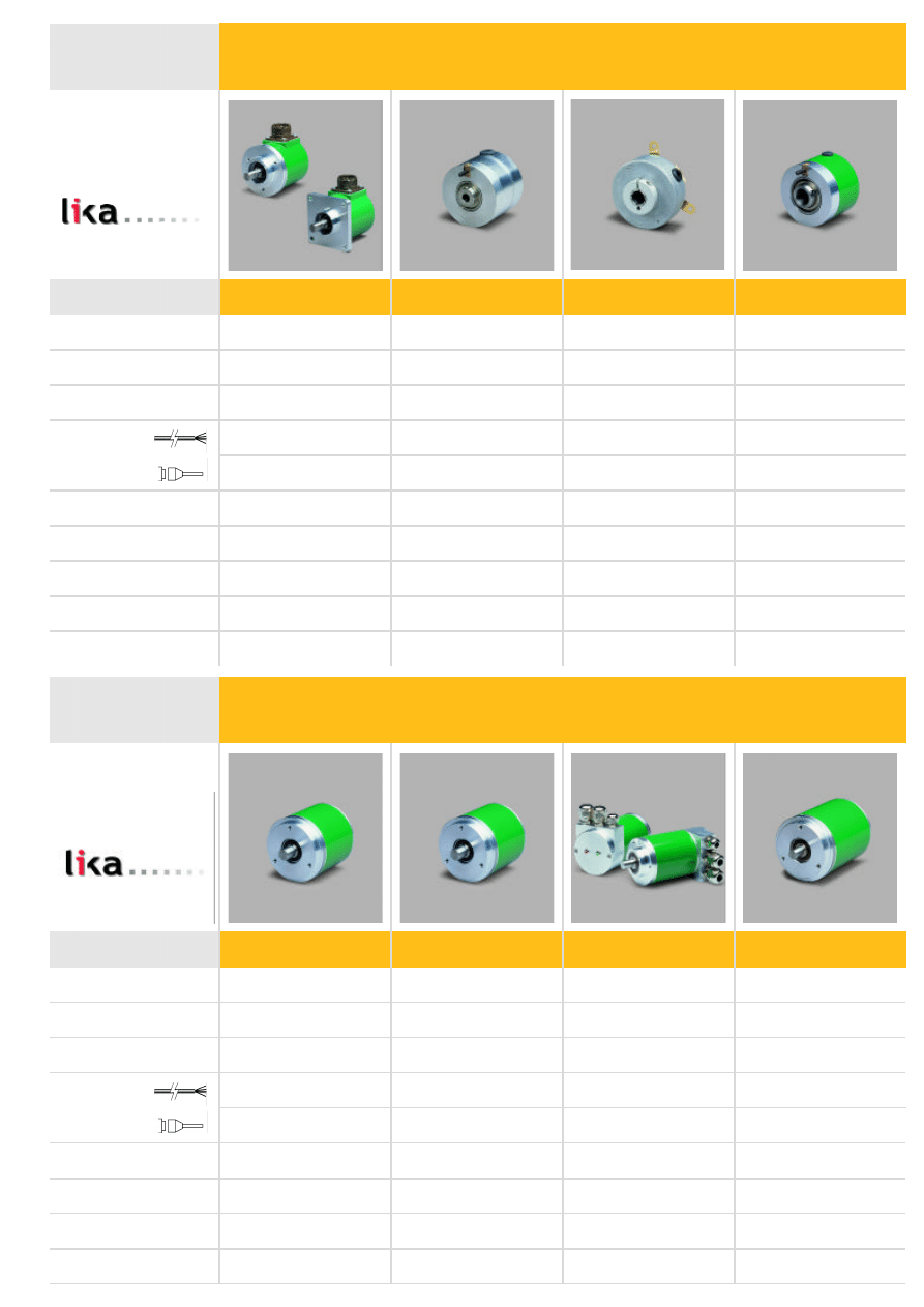
CK46
C50
C58, CK58
AS58 A
AS58, AM58 ISI
AM58 BUS
Features
Housing (mm)
Shaft ø (mm)
Connections
Resolution
Output freq. (kHz)
Output
Operating temperature
Protection
Series
Features
Housing (mm)
Shaft ø (mm)
Connections
Resolution
Output
Operating temperature
Protection
ROTAPULS incremental encoders
ROTACOD absolute encoders
AM58 P
46
6, 6.35
•
3600 max.
50 max.
Push-Pull, Line Driver
-40°C +100°C max.
IP54
50
6, 6.35, 8, 9.52, 10
•
2500 max.
100 max.
Push-Pull, Line Driver
-40°C +100°C max.
IP65 max.
•
•
58
14, 15
1000 max., 10000 max.
50 max., 300 max.
NPN, PNP, Push-Pull,
Line Driver
-40°C +100°C max.
IP65 max.
Fieldbus encoders
Programmable
58
6, 8, 9.52, 10, 12
•
•
13x12 bit max.
Push-Pull, SSI
-20°C +70°C
IP65
58
6, 8, 9.52, 10, 12
•
•
13x12 bit max.
ProfiBus, Interbus-S
DeviceNet, CAN Bus
-20°C +70°C
IP65
Analogue output
Incremental serial
interface
58
6, 8, 10, 12
•
•
12 bit
0-5V, 0-10V, 4-20 mA
-20°C +70°C
IP65
58
6, 8, 9.52, 10, 12
•
•
13 bit, 13x12 bit max.
ISI
-20°C +70°C
IP65
for motor applications
Series
C80, C81
CB50
EBOX
Features
Housing (mm)
Shaft ø (mm)
Connections
Resolution
Output freq. (kHz)
Output
Operating temperature
Protection
ROTAPULS incremental encoders
LINEPULS
•
80
6 ÷ 30, 20 ÷ 43.97
2500 max.
300 max.
Push-Pull, Line Driver
-40°C +100°C max.
IP65 max.
50
feedback encoder
for brushless motors
6, 6.35, 8, 9.52, 10
•
2500 max.
200
Push-Pull, Line Driver
-20°C +100°C max.
IP20
55 x 75 x 20
•
–
0,1 – 0,01 mm
Push-Pull, Line Driver
-10°C +70°C
IP40
Features
LD140
LCD 6 digit
1
96 x 72
Magnetic Sensor SM
< 10 m/s
Battery
RS232
–
LINEPULS
Series
Display
Nr. of axis
Dimensions (mm)
Sensor input
Speed
Supply
Interface
Outputs
LD120
PV1-V
MC150
LED 5 digit
1
72 x 36
Magnetic Sensor SM
< 10 m/s
+10 +30 Vdc
RS485
–
LCD 240x180 pixel
1 – 4
280 x 110
PP, LD
1,5 MHz max.
24 Vdc
RS232
12x 24 V @ 500 mA
± 10 V
LED 6 digit
1
96 x 72
PP, LD, SSI,
Magnetic Sensor SM
330 kHz max.
24 Vdc,
24, 115, 230 Vac
RS232
2x 24 V @ 500 mA
Digital Displays
for lift motors
Series
Nr. of axis
Interpolation
Auxiliary axis
Output
Analogue output
Programming
Display
from 4 to 12 axes simultaneously
6 axes linear/2 axes circ./helic.max.
independent, coupled, electrical, threading axes
192 IN optoins./192 OUT 4A optoins. max.
± 10 V (servo drive control)
EIA/ISO with macro, expressions, functions
TFT 10,4” colour
from 4 to 12 axes simultaneously
6 axes linear/2axes circ./helic. max.
independent, coupled, electrical, threading axes
192 IN optoins./192 OUT 4A optoins. max.
± 10 V (servo drive control)
EIA/ISO with macro, expressions, functions
NC’s & axis cards
Series
SME
SMS
SMK, SML, SMH
SMB
Features
Housing (mm)
Shaft ø (mm)
Connections
Resolution
Output freq. (kHz)
Output
Operating temperature
Protection
LINEPULS Magnetic Measurement System
25 x 40 x 10
sin / cos version
–
•
16 m/s max.
1 Vpp
-10°C +70°C
IP67
25 x 40 x 10
–
•
50 µm max.
5 m/s max.
Push-Pull, Line Driver
-10°C +70°C
IP67
–
•
5 µm max.
16 m/s max.
Push-Pull, Line Driver
-10°C +70°C
IP67
25 x 40 x 10
–
•
5 µm max.
16 m/s max.
Push-Pull, Line Driver
-10°C +70°C
IP67
-
LCN 4001
SA4
RD1
SAM3
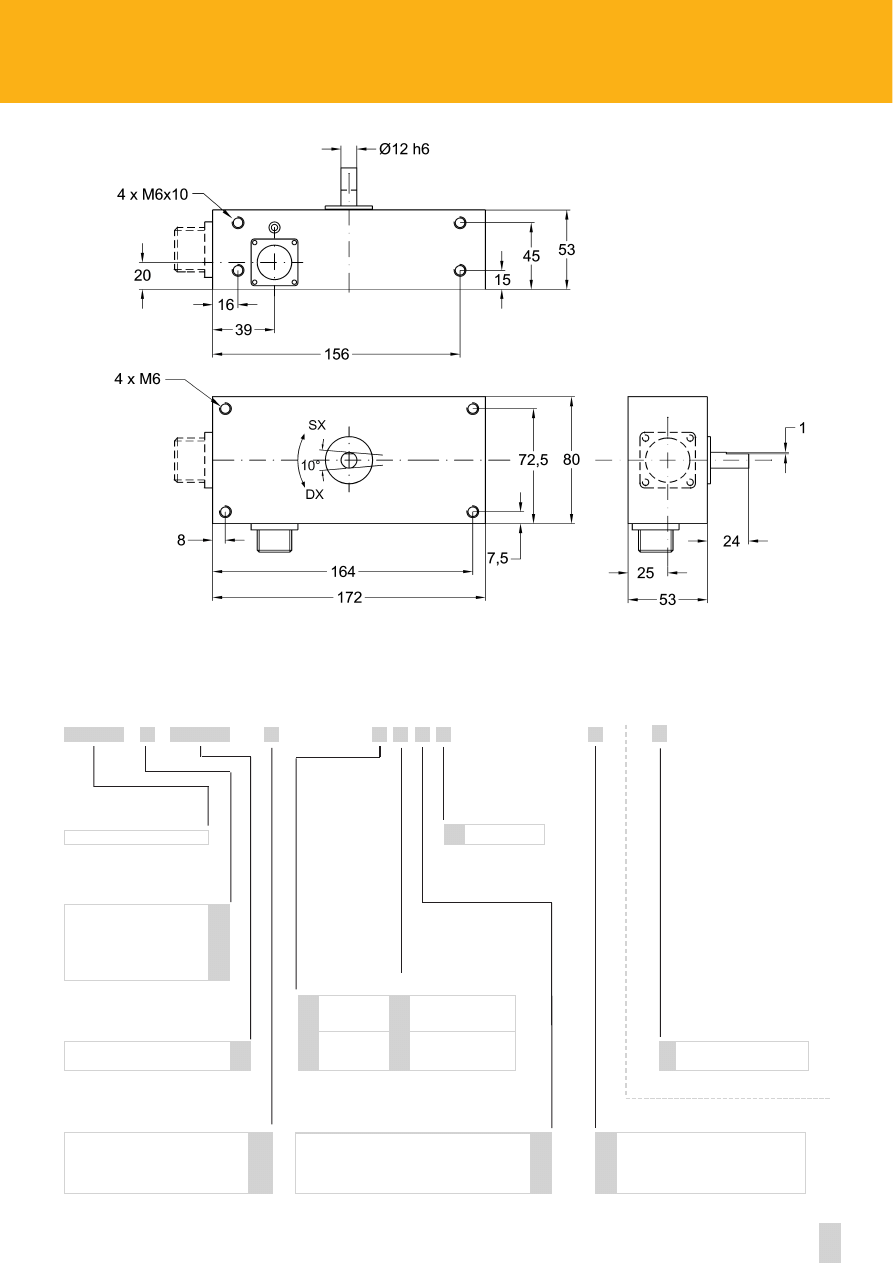
Positioning unit with integrated gear motor,
drive, positioner and encoder
1
70
5 max.
24 Vdc
RS485, CANopen, Profibus
incremental or absolute encoder integrated
integrated
58 x 125 x 105
Intelligent 3 axes drive with integrated positioner
3
380 max.
–
+24 +48 Vdc
RS232, CANopen, Profibus
3 x AB0, 3 x SSI
for DC motors
145 x 210 x 45
DRIVECOD
Series
Features
Nr. of axis
Output power (W)
Torque (Nm)
Supply
Interface
Feedback
Drive
Dimensions (mm)

INDEX
SHAFT ENCODERS
I28
1
I40, I41
3
I58, I58S
5
I58A, I58V (sin/cos)
7
I58C
9
I65, IT65
11
I105
13
ICS
15
HOLLOW SHAFT ENCODERS
CK46
17
C50
19
CB50 (feedback encoder for brushless motors)
21
C58, C59, C60
23
C58A, C58R
25
CK58, CK59, CK60
27
C80
29
C81
31
ABSOLUTE SINGLE TURN ENCODERS
AS5
33
AS58, AS58S, ASC58, ASC59, ASC60
35
AST6
37
SPECIAL ABSOLUTE ENCODERS
ASR58 (programmable cam encoder)
39
AS58 A (with analogue output)
41
Ax58 ISI (with incremental serial interface)
43
ABSOLUTE MULTITURN ENCODERS
AM5
45
AM58, AM58S, AMC58, AMC59, AMC60
47
AM58 P, AM58S P, AMC58 P (programmable encoder)
49
FIELDBUS ENCODERS
Ax58x Profibus-DP
51
Ax58x InterBus-S
53
Ax58x Devicenet
55
Ax58x CANopen
57
ELECTRICAL CONNECTIONS
Incremental encoders
59
Absolute encoders
61
AM58 P series
63
TECHNICAL INFORMATION
Mechanical dimensions with connector output
64
Fixing variations for hollow shaft encoders
65
Absolute encoders resolution schedules
66
Output circuits
67
- SSI output
68
- Shifted codes
70
- Latch, Tri-state, Complementary, Zero setting, Parity bit
71
Profibus-DP
72
InterBus-S
73
CAN and Devicenet
74
ACCESSORIES
Flexible couplings
75
Reducing sleeves
75
Fixing clamps
75
Metric wheels
75
Mounting bells
76
Adapting flanges
76
EEx housing
77
MOUNTING INSTRUCTIONS
Mounting instructions
78
Page
1
Specifications subject to changes without prior notice
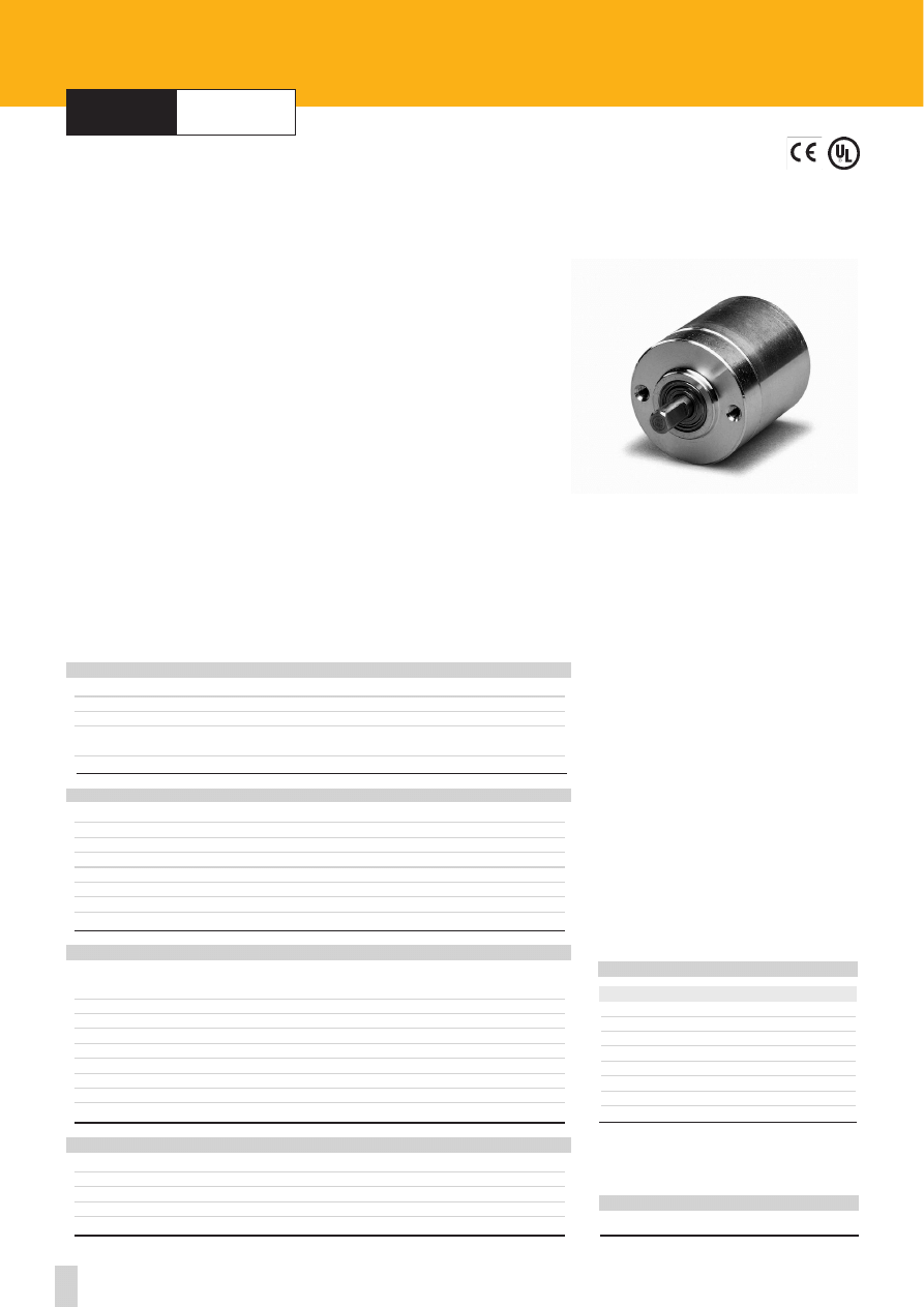
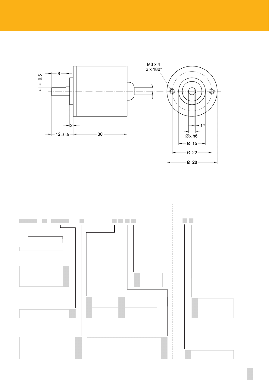
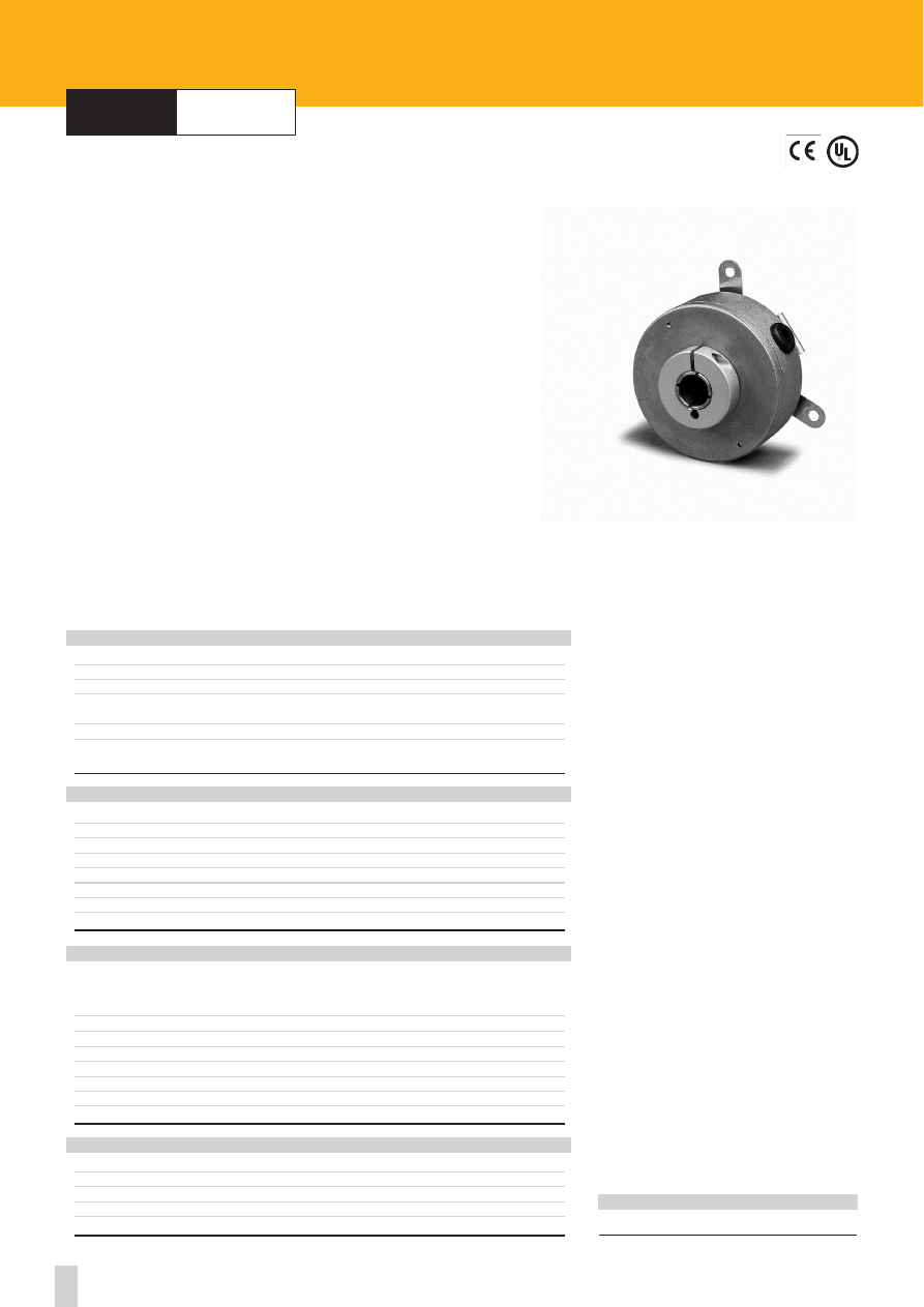
series
I28
I28
Shock:
100 g, 6 ms (acc. to MIL STD 202F)
Vibrations:
10 g, 5-2000 Hz (acc. to MIL STD 202F)
Operating temperature range:
-20°C +70°C (-4°F +158°F)
Storage temperature range:
-20°C +80°C (-4°F +176°F)
(98% R.H.without condensation)
Protection:
IP54
ENVIRONMENTAL SPECIFICATIONS
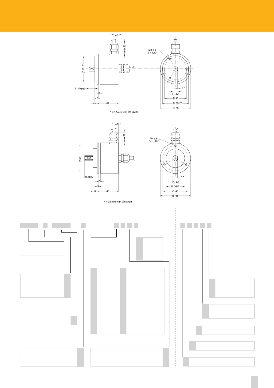
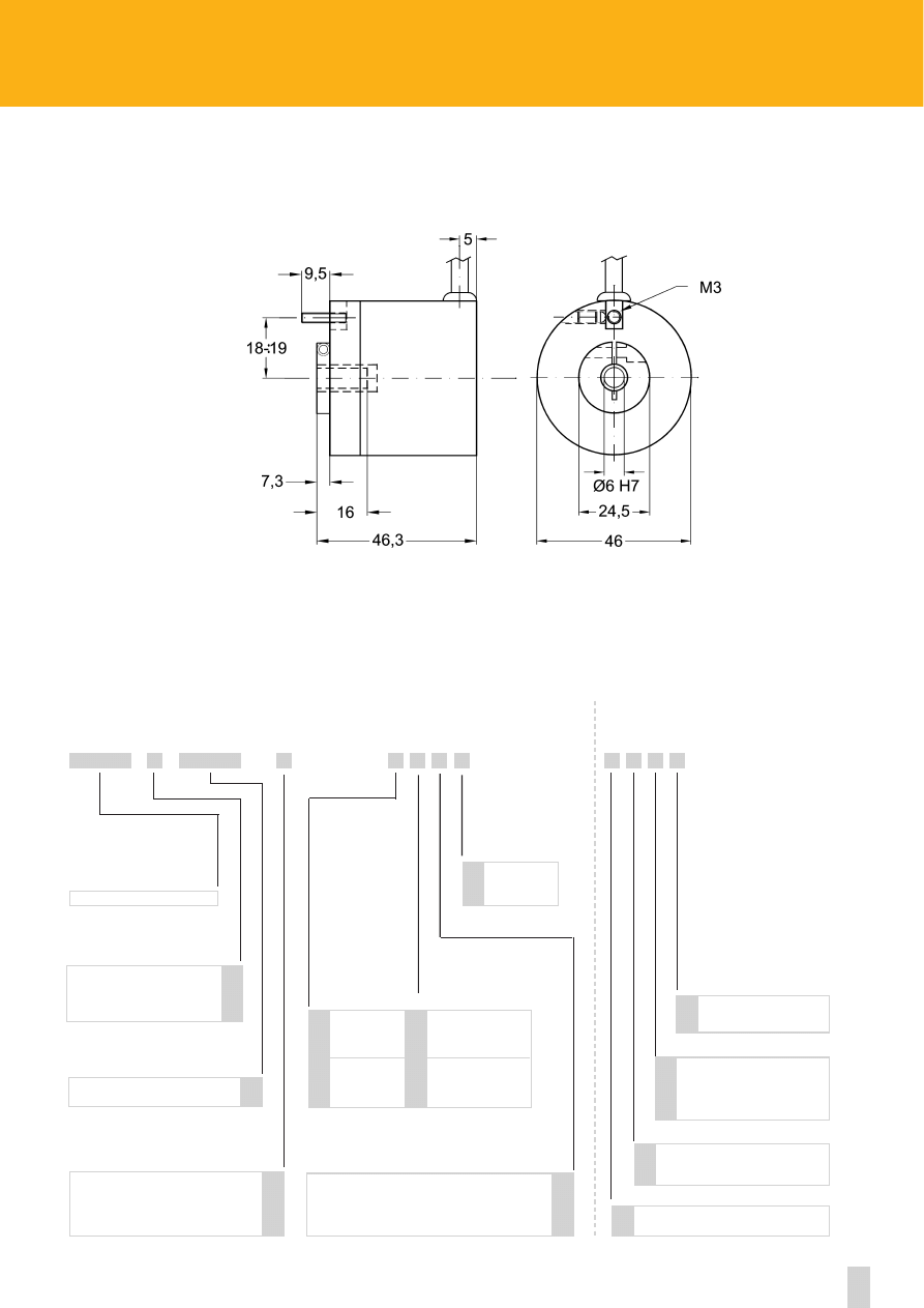
Dimensions:
see drawing
Shaft:
Ø 4, 5 mm
Shaft loading (axial and radial):
20 N max.
Shaft rotational speed:
3000 rpm max.
Starting torque at 20°C:
≤ 0,3 Ncm (typical)
Moment of inertia:
~10 gcm
2
Bearings life:
10
9
rev. min.
Weight:
~ 0,1 kg (3,5 oz)
MECHANICAL SPECIFICATIONS
Power supply:
+5V±5%, +10V +30V,+5V +30V
Output circuits:
Push-Pull, Line Driver, PP/LD
Output current (per channel):
40 mA max.
Output frequency:
30 kHz max.
Input current:
50 mA max.
Protection:
against inversion of polarity (except +5V version)
Optoelectronic life:
100.000 hrs min.
Option:
• Output frequency up to 100 kHz max.
STD pulse rate
(other PPR upon request):
ELECTRICAL SPECIFICATIONS
100-200-250-360-500-1024
Flange:
non corroding
Housing:
non corroding
Bearings:
ABEC 5
Shaft:
stainless steel, non-magnetic
Light source:
GaAl diodes
MATERIALS
ROTAPULS
Incremental encoders
8 wires cable
red-black
A
blue
/A
green
B
orange
/B
white
0
white-black
/0
red
+Vdc
black
0 Vdc
ELECTRICAL CONNECTIONS
ACCESSORIES
PAN/PGF:
flexible couplings
2
www.lika.biz
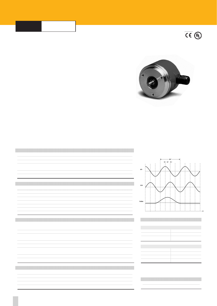
Bidirectional
Bidirectional with index pulse
See electrical specifications
Push-Pull
Line Driver AD26LS31 or eqv.
PP/LD universal circuit
I28
Cable length on request
Ex.: L4 = 4 meters (13.2 ft)
L7 = 7 meters (23.0 ft)
+5V±5% (L output circuit)
+10V÷ +30V (Y output circuit)
+5V÷+30V (PP/LD universal circuit)
Y
L
H
Lx
B
Z
1
2
4
4 mm
5 mm
4
5
SERIES
OUTPUT CIRCUITS
PULSE RATE (PPR)
OUTPUT SIGNALS CONFIGURATION
SHAFT DIAMETER
SUPPLY VOLTAGE VS OUTPUT CIRCUIT
XXXX
X
X
X X
X X X
X
ORDERING CODE
Output frequency up to 100 kHz
V
XXXX
-
-
ADDITIONAL CODE (indicate only if necessary)
5 wires cable, 1m (3.3 ft)
8 wires cable, 1m (3.3 ft)
Normal output
Complementary
outputs
N
C
F
U
ELECTRICAL CONNECTIONS
I28
3
Specifications subject to changes without prior notice
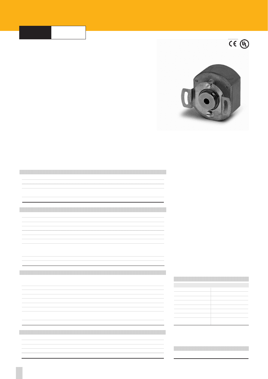
series
I40
•
I41
Shock:
100 g, 6 ms (acc. to MIL STD 202F)
Vibrations:
10 g, 5-2000 Hz (acc. to MIL STD 202F)
Operating temperature range:
-20°C +70°C (-4°F, +158°F)
Storage temperature range:
-20°C +80°C (-4°F +176°F)
(98% R.H.without condensation)
Protection:
IP54
Options:
• IP65 Protection (only I41)
• IP66 Protection shaft end (only I41)
ENVIRONMENTAL SPECIFICATIONS
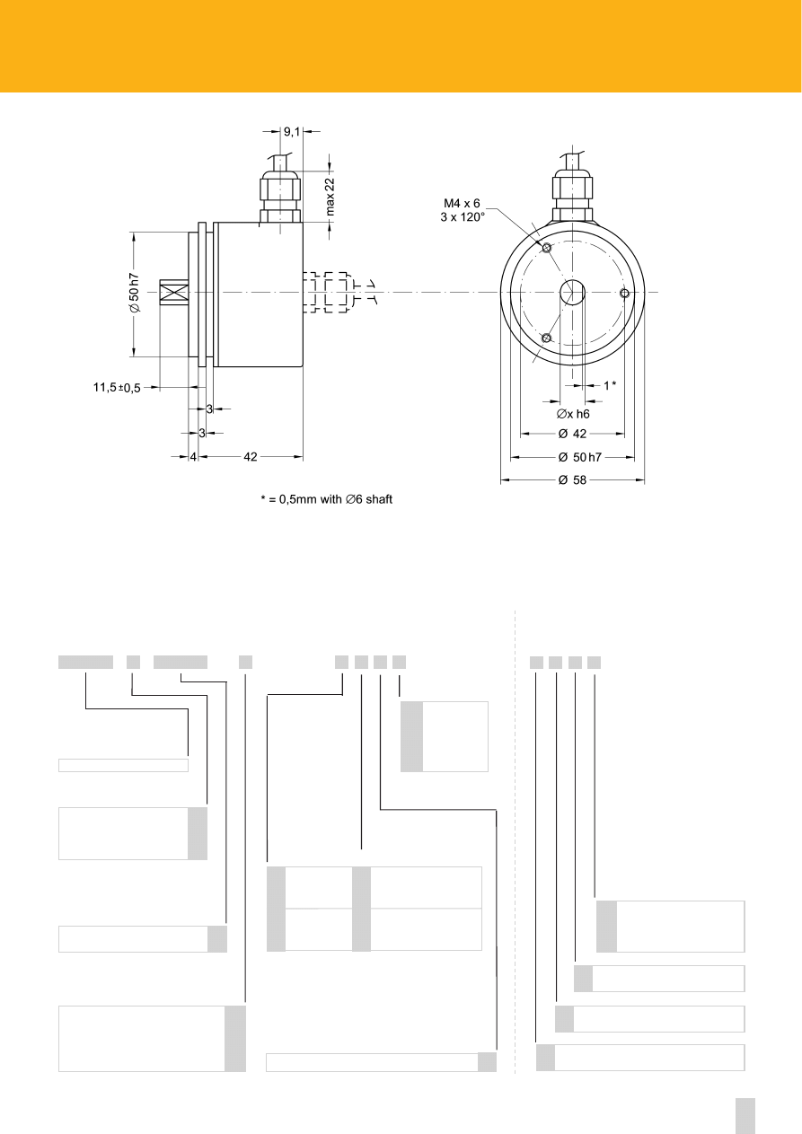
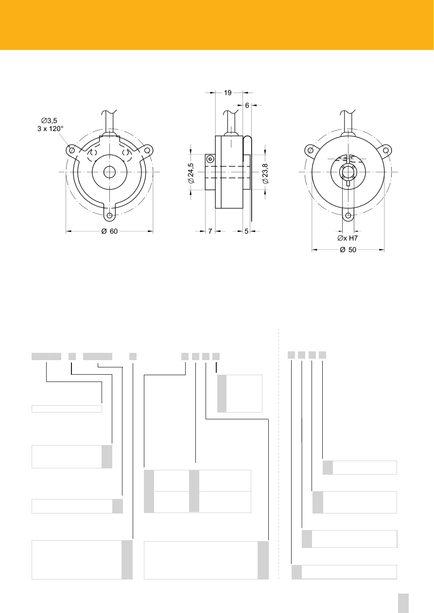
Dimensions:
see drawing
Shaft:
Ø 4, 6, 6.35, 8 mm
Shaft loading (axial and radial):
20 N max.
Shaft rotational speed:
6000 rpm max.
Starting torque at 20°C:
≤ 0,3 Ncm (typical)
Moment of inertia:
~20 gcm
2
Bearings life:
10
9
rev. min.
Weight:
~ 0,1 kg (3,5 oz)
MECHANICAL SPECIFICATIONS
Power supply:
+5V±5%, +10V +30V,+5V +30V
Output circuits:
NPN o.c., PNP o.c., Push-Pull, Line Driver, PP/LD
Output current (per channel):
40 mA max.
Output frequency:
50 kHz max.
Input current:
50 mA max.
Protection:
against inversion of polarity (except +5V version)
Optoelectronic life:
100.000 hrs min.
Option:
• Output frequency up to 100 kHz max.
STD pulse rate
(other PPR upon request):
ELECTRICAL SPECIFICATIONS
1-5-8-10-15-20-25-30-32-40-50-60-64-72-84
90-100-125-127-150-176-180-200-250-300-314
320-360-400-500-540-600-625-635-720-900
1000-1021-1024-1080-1200-1250-1500-1600
2000-2500-3000-3600
Flange:
non corroding
Housing:
fibre glass epoxy resin
Bearings:
ABEC 5
Shaft:
stainless steel, non-magnetic
Light source:
GaAl diodes
MATERIALS
I41
I40
ROTAPULS
Incremental encoders
ACCESSORIES
EDE9S:
9 pin DSub mating connector
PAN/PGF:
flexible couplings
LKM-386:
fixing clamps
4
www.lika.biz
Inline connector DSub 9 pin
C
I40
I41
Bidirectional
Bidirectional with index pulse
See electrical specifications
NPN o.c.
PNP o.c.
Push-Pull
Line Driver AD26LS31 or equiv.
PP/LD universal circuit
I40 - I41
IP65 Protection (only I41)
IP66 Protection shaft end (only I41)
Cable length on request
Ex.: L4 = 4 meters (13.2 ft)
L7 = 7 meters (23.0 ft)
+5V±5% (L output circuit)
+10V÷ +30V (N, P and Y output circuits)
+5V÷ +30V (PP/LD universal circuit)
N
P
Y
L
H
Side mount cable
R
Lx
P
Q
B
Z
1
2
4
4 mm
6 mm
6.35 mm / 1/4”
8 mm
4
6
6.35
8
SERIES
OUTPUT CIRCUITS
PULSE RATE (PPR)
OUTPUT SIGNALS CONFIGURATION
SHAFT DIAMETER
SUPPLY VOLTAGE VS OUTPUT CIRCUIT
XXXX
X
X
X X X X X
X X X
X
ORDERING CODE
Output frequency up to 100 kHz
V
XXXX
-
-
ADDITIONAL CODE (indicate only if necessary)
5 wires cable, 1m. (3.3 ft)
8 wires cable, 1m. (3.3 ft)
see on page 59-60
Normal output
Complementary
outputs
N
C
F
U
ELECTRICAL CONNECTIONS
5
Specifications subject to changes without prior notice
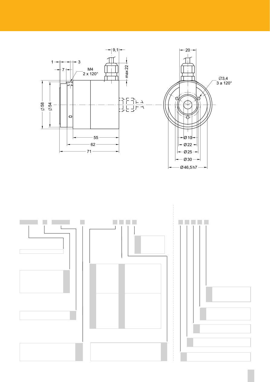
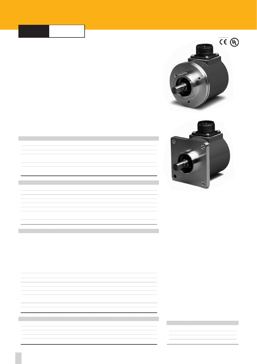
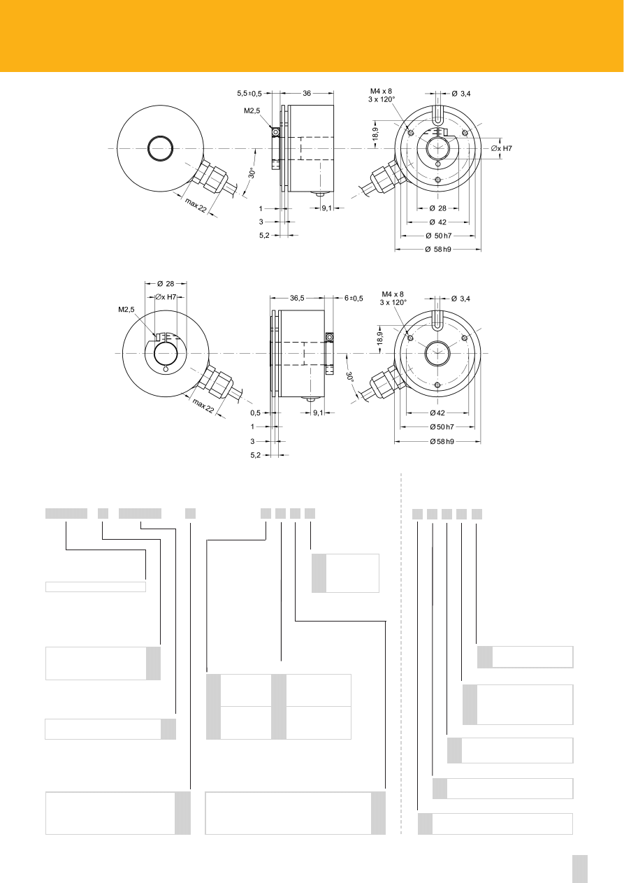
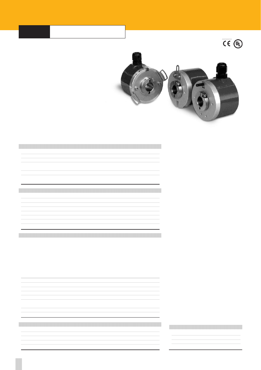
series
I58
•
I58S
I58
I58S
Shock:
100 g, 6 ms (acc. to MIL STD 202F)
Vibrations:
10 g, 5-2000 Hz (acc. to MIL STD 202F)
Operating temperature range:
-20°C +70°C (-4°F +158°F)
Storage temperature range:
-20°C +80°C (-4°F +176°F)
(98% R.H.without condensation)
Protection:
IP64
Options:
• Operating temperature range: -40°C +100°C (-40°F, +212°F)
• IP65 Protection
ENVIRONMENTAL SPECIFICATIONS
Dimensions:
see drawing
Shaft:
Ø 6, 8, 9.52, 10, 12 mm
Shaft loading (axial and radial):
20 N max I58
40 N max I58S
Shaft rotational speed:
6000 rpm max.
Starting torque at 20°C:
≤ 1 Ncm (typical)
Moment of inertia:
~15 gcm
2
Bearings life:
10
9
rev. min.
Weight:
~ 0,3 kg (10,6 oz)
MECHANICAL SPECIFICATIONS
Power supply:
+5V±5%, +10V +30V,+5V +30V
Output circuits:
NPN o.c., PNP o.c., Push-Pull, Line Driver, PP/LD
Output current (per channel):
40 mA max.
Output frequency:
100 kHz max.
Input current:
70 mA max.
Protection:
against inversion of polarity (except +5V version)
outputs are protected against short-circuit (except Line Driver version)
Optoelectronic life:
100.000 hrs min.
Option:
• Output frequency up to 300 kHz max.
STD pulse rate
(other PPR upon request):
ELECTRICAL SPECIFICATIONS
2-4-5-6-10-12-15-16-18-20-24-25-30-35-36-39
4 0 - 4 5 - 5 0 - 6 0 - 6 4 - 7 0 - 8 0 - 9 0 - 1 0 0 - 1 2 0 - 1 2 2
125 -1 27 -14 2 - 150 - 1 80- 2 0 0- 21 6 - 236 - 2 40
250 -2 54 -25 6 - 267 - 2 70- 3 0 0- 31 4 - 360 - 3 75
400 -4 10 -43 3 - 435 - 4 71- 5 0 0- 51 2 - 600 - 6 25
628 -6 35 -72 0 - 750 - 7 84- 8 0 0- 87 5 - 900 - 9 46
1000-1068-1099-1200-1250-1270-1440-1500
1800-2000-2250-2400-2500-3000-3600-4000
4096-5000-6000-9000-10000
Flange:
non corroding
Housing:
non corroding
Bearings:
ABEC 5
Shaft:
stainless steel, non-magnetic
Light source:
GaAl diodes
MATERIALS
ROTAPULS
Incremental encoders
ACCESSORIES
E7MLS:
7 pin MIL mating connector
E10MLS:
10 pin MIL mating connector
T3475001:
7 pin TUCHEL mating connector
T3635000:
12 pin TUCHEL mating connector
EPFL 121: 12 pin CONNEI mating connector
PAN/PGF:
flexible couplings
LKM-386:
fixing clamps
6
www.lika.biz
Bidirectional
Bidirectional with index pulse
See electrical specifications
NPN o.c.
PNP o.c.
Push-Pull
Line Driver AD26LS31 or equiv.
PP/LD universal circuit
I58 - I58S
IP65 Protection
Cable length on request
Ex.: L4 = 4 meters (13.2 ft)
L7 = 7 meters (23.0 ft)
Operating temperature range:
-40°C + 100°C (-40°F +212°F)
+5V±5% (L output circuit)
+10V ÷ +30V (N, P and Y output circuits)
+5V ÷ +30V (PP/LD universal circuit)
5 wires cable, 1m. (3.3 ft)
7 pin TUCHEL connector
7 pin IP65 MIL connector
8 wires cable, 1 meter (3.3 ft)
12 pin TUCHEL connector
10 pin IP65 MIL connector
12 pin CONNEI connector
N
P
Y
L
H
Side mount cable or connector
R
Lx
P
K
B
Z
1
2
4
Normal output
Complementary
outputs
N
C
F
C
D
U
V
P
Z
6 mm
8 mm
9.52 mm / 3/8”
10 mm
12 mm
6
8
9.52
10
12
SERIES
OUTPUT CIRCUITS
PULSE RATE (PPR)
OUTPUT SIGNALS CONFIGURATION
SHAFT DIAMETER
ELECTRICAL CONNECTIONS
SUPPLY VOLTAGE VS OUTPUT CIRCUIT
XXXX
X
X
X X X X X
X X X
X
ORDERING CODE
Output frequency up to 300 kHz
W
XXXX
-
-
ADDITIONAL CODE (indicate only if necessary)
(1) Mechanical dimensions with connector
output see page 64
I58
I58S
(1)
(1)
see on page 59-60
7
Specifications subject to changes without prior notice
series
I58A
•
I58V
Shock:
100 g, 6 ms (acc. to MIL STD 202F)
Vibrations:
10 g, 5-2000 Hz (acc. to MIL STD 202F)
Operating temperature range:
-20°C +70°C (-4°F +158°F)
Storage temperature range:
-20°C +80°C (-4°F +176°F)
(98% R.H.without condensation)
Protection:
IP64
Option:
• IP65 Protection
ENVIRONMENTAL SPECIFICATIONS
Dimensions:
see drawing
Shaft:
Ø 6, 8, 9.52, 10, 12 mm
Shaft loading (axial and radial):
20 N max I58
Shaft rotational speed:
6000 rpm max.
Starting torque at 20°C:
≤ 1 Ncm (typical)
Moment of inertia:
~15 gcm
2
Bearings life:
10
9
rev. min.
Weight:
~ 0,3 kg (10,6 oz)
MECHANICAL SPECIFICATIONS
Power supply:
5V ± 5%
Output signals I58A:
A,B: 11 µApp - Index: 5,5 µA (load 1 k
Ω)
I58V:
A,B: 1 Vpp - Index: 0,4 V (load 120 k
Ω)
Output frequency:
50 kHz max.
Input current (without load):
70 mA max.
Protection:
against inversion of polarity (except +5V version)
outputs are protected against short-circuit (except +5V version)
Optoelectronic life:
100.000 hrs min.
Option:
• Output frequency up to 100 kHz max.
STD pulse rate
(other PPR upon request):
ELECTRICAL SPECIFICATIONS
500-512-1000-1024-1250-2000-2048-2500
Flange:
non corroding
Housing:
non corroding
Bearings:
ABEC 5
Shaft:
stainless steel, non-magnetic
Light source:
GaAl diodes
MATERIALS
5 wires cable (1 m, 3,3ft)
black
0 Vdc blue
COS
red
+ Vdc white
Index
brown
SIN
ELECTRICAL CONNECTIONS
with normal outputs
with complementary outputs
8 wires cable (1 m, 3,3ft)
yellow
SIN+ white
Index+
blue
SIN- grey
Index-
green
COS+ red
+ Vdc
orange
COS- black
0 Vdc
I58A-I58V
ROTAPULS
Incremental Encoders with sinusoidal outputs
ACCESSORIES
PAN/PGF:
flexible couplings
LKM-386:
fixing clamps
8
www.lika.biz
Bidirectional
Bidirectional with index pulse
See electrical specifications
11 µApp (current)
1 Vpp (voltage)
I58
Cable length on request
Ex.: L4 = 4 m (13.2 ft)
L7 = 7 m (23.0 ft)
IP65 Protection
+5 Vdc ±5%
5 wires cable, 1m. (3.3 ft)
8 wires cable, 1 m. (3.3 ft)
A
V
Lx
Side mount cable
R
P
B
Z
1
Normal output
Complementary
outputs
N
C
F
U
SERIES
OUTPUT CIRCUITS
PULSE RATE (PPR)
OUTPUT SIGNALS CONFIGURATION
SHAFT DIAMETER
ELECTRICAL CONNECTIONS
SUPPLY VOLTAGE VS OUTPUT CIRCUIT
XXXX
X
X
X X X X
X X X
X
ORDERING CODE
Output frequency up to 100 kHz
V
XXXX
-
-
ADDITIONAL CODE (indicate only if necessary)
I58A-I58V
6 mm
8 mm
9.52 mm / 3/8”
10 mm
12 mm
6
8
9.52
10
12
see on page 59-60
9
Specifications subject to changes without prior notice
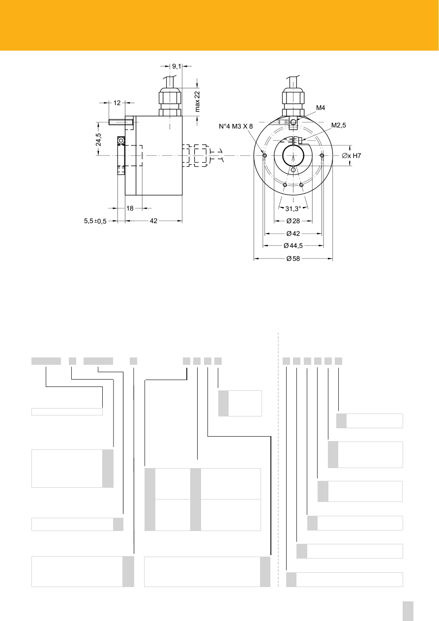
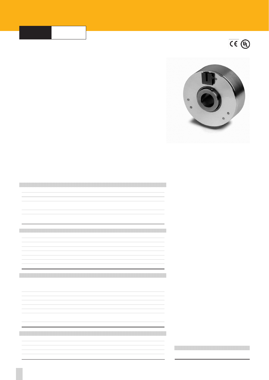
series
I58C
I58C
Shock:
100 g, 6 ms (acc. to MIL STD 202F)
Vibrations:
10 g, 5-2000 Hz (acc. to MIL STD 202F)
Operating temperature range:
-20°C +70°C (-4°F +158°F)
Storage temperature range:
-20°C +80°C (-4°F +176°F)
(98% R.H.without condensation)
Protection:
IP64
Options:
• Operating temperature range: -40°C +100°C (-40°F +212°F)
• IP65 Protection
ENVIRONMENTAL SPECIFICATIONS
Dimensions:
see drawing
Shaft hollow:
Ø 6, 8, 10, 12 mm
Shaft rotational speed:
6000 rpm max.
Starting torque at 20°C:
≤ 1 Ncm (typical)
Moment of inertia:
~15 gcm
2
Bearings life:
10
9
rev. min.
Weight:
~ 0,3 kg (10,6 oz)
MECHANICAL SPECIFICATIONS
Power supply:
+5V±5%, +10V +30V,+5V +30V
Output circuits:
NPN o.c., PNP o.c., Push-Pull, Line Driver, PP/LD
Output current (per channel):
40 mA max.
Output frequency:
100 kHz max.
Input current:
70 mA max.
Protection:
against inversion of polarity (except +5V version)
outputs are protected against short-circuit (except Line Driver version)
Optoelectronic life:
100.000 hrs min.
Option:
• Output frequency up to 300 kHz max.
STD pulse rate:
(other PPR upon request)
ELECTRICAL SPECIFICATIONS
2-4-5-6-10-12-15-16-18-20-24-25-30-35-36-39
4 0 - 4 5 - 5 0 - 6 0 - 6 4 - 7 0 - 8 0 - 9 0 - 1 0 0 - 1 2 0 - 1 2 2
125 -1 27 -14 2 - 150 - 1 80- 2 0 0- 21 6 - 236 - 2 40
250 -2 54 -25 6 - 267 - 2 70- 3 0 0- 31 4 - 360 - 3 75
400 -4 10 -43 3 - 435 - 4 71- 5 0 0- 51 2 - 600 - 6 25
628 -6 35 -72 0 - 750 - 7 84- 8 0 0- 87 5 - 900 - 9 46
1 0 0 0 - 1 0 2 4 - 1 0 6 8 - 1 0 9 9 - 1 2 0 0 - 1 2 5 0 - 1 2 7 0
1440-1500-1800-2000-2048-2250-2400-2500
3000-3600-4000-4096-5000-6000-9000-10000
Flange:
non corroding
Housing:
non corroding
Bearings:
ABEC 5
Shaft:
stainless steel, non-magnetic
Light source:
GaAl diodes
MATERIALS
www.lika.biz
- mounting instructions
ROTAPULS
Incremental encoders
ACCESSORIES
E7MLS:
7 pin MIL mating connector
E10MLS:
10 pin MIL mating connector
T3475001:
7 pin TUCHEL mating connector
T3635000:
12 pin TUCHEL mating connector
EPFL 121: 12 pin CONNEI mating connector
PAN/PGF:
flexible couplings
I58C
10
www.lika.biz
Bidirectional
Bidirectional with index pulse
See electrical specifications
NPN o.c.
PNP o.c.
Push-Pull
Line Driver AD26LS31 or eqv.
PP/LD universal circuit
IP65 Protection
Cable length on request
Ex.: L4 = 4 m (13.2 ft)
L7 = 7 m (23.0 ft)
Operating temperature range:
-40°C + 100°C (-40°F +212°F)
+5V±5% (L output circuit)
+10V÷ +30V (N, P and Y output circuits)
+5V÷+30V (PP/LD universal circuit)
5 wires cable, 1m. (3.3 ft)
7 pin connector TUCHEL
7 pin IP65 MIL connector
8 wires cable, 1 m. (3.3 ft)
12 pin TUCHEL connector
10 pin IP65 MIL connector
12 pin CONNEI connector
N
P
Y
L
H
Side mount cable or connector
R
Lx
P
K
B
Z
1
2
4
Normal output
Complementary
outputs
N
C
F
C
D
U
V
P
Z
6 mm
8 mm
10 mm
12 mm
6
8
10
12
SERIES
OUTPUT CIRCUITS
PULSE RATE (PPR)
OUTPUT SIGNALS CONFIGURATION
SHAFT DIAMETER
ELECTRICAL CONNECTIONS
SUPPLY VOLTAGE VS OUTPUT CIRCUIT
XXXX
X
X
X X X X X
X X X
X
ORDERING CODE
Output frequency up to 300 kHz
W
XXXX
-
-
ADDITIONAL CODE (indicate only if necessary)
I58C
(1) Mechanical dimensions with connector output see on page 64
(1)
see on page 59-60
11
Specifications subject to changes without prior notice
series
I65
•
IT65
I65
IT65
Shock:
100 g, 6 ms (acc. to MIL STD 202F)
Vibrations:
10 g, 5-2000 Hz (acc. to MIL STD 202F)
Operating temperature range: -20°C+70°C (-4°F +158°F)
Storage temperature range:
-20°C +80°C (-4°F +176°F)
(98% R.H.without condensation)
Protection:
IP65
Options:
• Operating temperature range: -40°C +100°C (-40°F +212°F)
• IP66 Protection shaft end (torque 2,5 Ncm and 3000 rpm max.)
ENVIROMENTAL SPECIFICATIONS
Dimensions:
see drawing
Shaft:
Ø 6, 8, 9.52, 10, 12 mm
Shaft loading (axial and radial):
100 N max.
Shaft rotational speed:
6000 rpm max.
Starting torque at 20°C:
≤ 1,5 Ncm (typical)
Moment of inertia:
~ 50 gcm
2
Bearings life:
400x10
6
rev. min.
(10
9
rev. min. with 20 N shaft loading max)
Weight:
~ 0,3 kg (10,6 oz)
MECHANICAL SPECIFICATIONS
Power supply:
+5V±5%, +10V +30V,+5V +30V
Output circuits:
NPN o.c., PNP o.c., Push-Pull, Line Driver, PP/LD
Output current (per channel):
40 mA max.
Output frequency:
100 kHz max.
Input current:
70 mA max.
Protection:
against inversion of polarity (except +5V version)
outputs are protected against short-circuit (except Line Driver version)
Optoelectronic life:
100.000 hrs min.
Option:
• Output frequency up to 300 kHz max.
STD pulse rate:
(other PPR upon request)
ELECTRICAL SPECIFICATIONS
2-4-5-6-10-12-15-16-18-20-24-25-30-35-36-39
4 0 - 4 5 - 5 0 - 6 0 - 6 4 - 7 0 - 8 0 - 9 0 - 1 0 0 - 1 2 0 - 1 2 2
125 -1 27 -14 2 - 150 - 1 80- 2 0 0- 21 6 - 236 - 2 40
250 -2 54 -25 6 - 267 - 2 70- 3 0 0- 31 4 - 360 - 3 75
400 -4 10 -43 3 - 435 - 4 71- 5 0 0- 51 2 - 600 - 6 25
628 -6 35 -72 0 - 750 - 7 84- 8 0 0- 87 5 - 900 - 9 46
1 0 0 0 - 1 0 2 4 - 1 0 6 8 - 1 0 9 9 - 1 2 0 0 - 1 2 5 0 - 1 2 7 0
1440-1500-1800-2000-2048-2250-2400-2500
3000-3600-4000-4096-5000-6000-9000-10000
Flange:
non corroding
Housing:
non corroding
Bearings:
ABEC 5
Shaft:
stainless steel, non-magnetic
Light source:
GaAl diodes
MATERIALS
ROTAPULS
Incremental encoders
ACCESSORIES
E7MLS:
7 pin MIL mating connector
E10MLS:
10 pin MIL mating connector
PAN/PGF: flexible
couplings
LKM-386:
fixing clamps
I65 - IT65
12
www.lika.biz
Bidirectional
Bidirectional with index pulse
See electrical specifications
NPN o.c.
PNP o.c.
Push-Pull
Line Driver AD26LS31 or eqv.
PP/LD universal circuit
IP66 Protection shaft side
Cable length on request
Ex.: L4 = 4 m (13.2 ft)
L7 = 7 m (23.0 ft)
Operating temperature range:
-40°C + 100°C (-40°F +212°F)
+5V±5% (L output circuit)
+10V÷ +30V (N, P and Y output circuits)
+5V÷+30V (PP/LD universal circuit)
N
P
Y
L
H
Side mount cable or connector
R
Lx
Q
K
B
Z
1
2
4
6 mm
8 mm
9.52 mm / 3/8”
10 mm
12 mm
B
C
D
E
F
SERIES
OUTPUT CIRCUITS
PULSE RATE (PPR)
OUTPUT SIGNALS CONFIGURATION
SHAFT DIAMETER
SUPPLY VOLTAGE VS OUTPUT CIRCUIT
XXXX
X
X
X X X X X
X X X
X
ORDERING CODE
Output frequency up to 300 kHz
W
XXXX
-
-
ADDITIONAL CODE (indicate only if necessary)
Normal output
5 wires cable, 1m. (3.3 ft)
7 pin IP65 MIL connector
8 wires cable, 1m. (3.3 ft)
10 pin IP65 MIL connector
Complementary
outputs
N
C
F
D
U
P
ELECTRICAL CONNECTIONS
I65
IT65
see on page 59-60
13
Specifications subject to changes without prior notice
series
I105
I105
Shock:
100 g, 6 ms (acc. to MIL STD 202F)
Vibrations:
10 g, 5-2000 Hz (acc. to MIL STD 202F)
Operating temperature range:
-20°C+70°C (-4°F +158°F)
Storage temperature range:
-20°C+80°C (-4°F +176°F)
(98% R.H.without condensation)
Protection:
IP64
Options:
• Operating temperature range: -40°C +100°C (-40°F +212°F)
• IP65 protection
ENVIRONMENTAL SPECIFICATIONS
Dimensions:
see drawing
Shaft:
Ø 10 mm
Shaft loading (axial and radial):
40 N max.
Shaft rotational speed:
6000 rpm max.
Starting torque at 20°C:
≤ 1 Ncm (typical
Moment of inertia:
~25 gcm
2
Bearings life:
10
9
rev. min.
Weight:
~ 0,9 kg (31,7 oz)
MECHANICAL SPECIFICATIONS
Power supply:
+5V±5%, +10V +30V,+5V +30V
Output circuits:
Push-Pull, Line Driver, PP/LD
Output current (per channel):
40 mA max.
Output frequency:
100 kHz max.
Input current:
100 mA max.
Protection:
against inversion of polarity (except +5V version)
outputs are protected against short-circuit (except Line Driver version)
Optoelectronic life:
100.000 hrs min.
Option:
• Output frequency up to 300 kHz max.
STD pulse rate:
(other PPR upon request)
ELECTRICAL SPECIFICATIONS
16384-18000
Flange:
non corroding
Housing:
non corroding
Bearings:
ABEC 5
Shaft:
stainless steel, non-magnetic
Light source:
GaAl diodes
MATERIALS
ROTAPULS
Incremental encoders
ACCESSORIES
EPFL 121:
12 pin CONNEI mating connector
PAN/PGF: flexible
couplings
LKM-386:
fixing clamps
14
www.lika.biz
8 wires cable, 1 m. (3.3 ft)
12 pin CONNEI connector
Complementary
outputs
C
U
Z
ELECTRICAL CONNECTIONS
I105
Bidirectional
Bidirectional with index pulse
See electrical specifications
Push-Pull
Line Driver AD26LS31 or eqv.
PP/LD universal circuit
I105
IP65 Protection
Cable length on request
Ex.: L4 = 4 m (13.2 ft)
L7 = 7 m (23.0 ft)
Operating temperature range:
-40°C + 100°C (-40°F +212°F)
+5V±5% (L output circuit)
+10V÷ +30V (Y output circuit)
+5V÷ +30V (PP/LD universal circuit)
Y
L
H
Lx
P
K
B
Z
1
2
4
10 mm
10
SERIES
OUTPUT CIRCUITS
PULSE RATE (PPR)
OUTPUT SIGNALS CONFIGURATION
SHAFT DIAMETER
SUPPLY VOLTAGE VS OUTPUT CIRCUIT
XXXXX
X
X
X X X X
X X X
X
ORDERING CODE
Output frequency up to 300 kHz
W
XXXX
-
-
ADDITIONAL CODE (indicate only if necessary)
see on page 59-60
15
Specifications subject to changes without prior notice
series
ICS
Shock:
100 g, 6 ms (acc. to MIL STD 202F)
Vibrations:
10 g, 5-2000 Hz (acc. to MIL STD 202F)
Operating temperature range:
-20°C +70°C (-4°F +158°F)
Storage temperature range:
-20°C +80°C (-4°F +176°F)
(98% R.H.without condensation)
Protection:
IP65
ENVIRONMENTAL SPECIFICATIONS
Dimensions:
see drawing
Shaft:
Ø 12 mm
Shaft loading (axial and radial):
100 N max.
Shaft rotational speed:
6000 rpm max.
Starting torque at 20°C:
≤ 3 Ncm (typical)
Moment of inertia:
~250 gcm
2
Bearings life:
400x10
6
rev. min.
(10
9
rev. min. with 20 N shaft loading max)
Weight:
~ 1,2 kg (42,3 oz)
MECHANICAL SPECIFICATIONS
Pulses/mm:
to be result of pinion and rack ratio
Power supply:
+5V±5%, +10V +30V,+5V +30V
Output circuits:
NPN o.c., PNP o.c., Push-Pull, Line Driver, PP/LD
Output current (per channel):
40 mA max.
Output frequency:
60 kHz max.
Input current:
70 mA max.
Protection:
against inversion of polarity (except +5V version)
outputs are protected against short-circuit (except Line Driver version)
Optoelectronic life:
100.000 hrs min.
STD pulse rate
(other PPR upon request):
ELECTRICAL SPECIFICATIONS
2-4-5-6-10-12-15-16-18-20-24-25-30-35-36-39
40-45-50-60-64-70-80-90-100-120-122-125-127
142-150-180-200-216-236-240-250-254-256
267-270-300-314-360-375-400-410-433-435
471-500-512-600-625-628-635-720-750-784
800-875-900-946-1000-1024-1068
Housing:
non corroding
Bearings:
ABEC 5
Shaft:
stainless steel, non-magnetic
Light source:
GaAl diodes
MATERIALS
www.lika.biz
- application info
- pinion + rack drawing
ROTAPULS
Incremental encoders
ACCESSORIES
E7MLS:
7 pin MIL mating connector
E10MLS:
10 pin MIL mating connector
LKM-1225:
Z40 pinion
LKM-1224:
M0,79 rack
ICS
16
www.lika.biz
ICS
Bidirectional
Bidirectional with index pulse
See electrical specifications
NPN o.c.
PNP o.c.
Push-Pull
Line Driver AD26LS31 or eqv.
PP/LD universal circuit
ICS
Side mount connector
+5V±5% (L output circuit)
+10V÷ +30V (N, P and Y output circuits)
+5V÷ +30V (PP/LD universal circuit)
N
P
Y
L
H
R
B
Z
1
2
4
12 mm
F
SERIES
OUTPUT CIRCUITS
PULSE RATE (PPR)
OUTPUT SIGNALS CONFIGURATION
SHAFT DIAMETER
SUPPLY VOLTAGE VS OUTPUT CIRCUIT
XXXX
X
X
X
X
X X X
X
ORDERING CODE
XXXX
-
-
ADDITIONAL CODE (indicate only if necessary)
7 pin IP65 MIL connector
10 pin IP65 MIL connector
(only radial)
Normal output
Complementary
outputs
ELECTRICAL CONNECTIONS
N
C
D
P
Right (see drawing)
Left (see drawing)
DX
SX
AT REST POSITION
see on page 59-60
17
Specifications subject to changes without prior notice
CK46
series
CK46
Shock:
100 g, 6 ms (acc. to MIL STD 202F)
Vibrations:
10 g, 5-2000 Hz (acc. to MIL STD 202F)
Operating temperature range:
-20°C +70°C (-4°F +158°F)
Storage temperature range:
-20°C +80°C (-4°F +176°F)
(98% R.H.without condensation)
Protection:
IP64
Options:
• Operating temperature range: -40°C +100°C (-40°F +212°F)
• IP65 Protection (3000 rpm max, torque 1 Ncm)
ENVIRONMENTAL SPECIFICATIONS
Dimensions:
see drawing
Shaft hollow:
Ø 6, 6.35 mm
Shaft loading (axial and radial):
20 N max.
Shaft rotational speed:
6000 rpm max.
Starting torque at 20°C:
≤ 0,5 Ncm (typical)
Moment of inertia:
~20 gcm
2
Bearings life:
10
9
rev. min.
Weight:
~ 0,2 kg (7,0 oz)
MECHANICAL SPECIFICATIONS
Power supply:
+5V±5%, +10V +30V,+5V +30V
Output circuits:
Push-Pull, Line Driver, PP/LD
Output current (per channel):
40 mA max.
Output frequency:
60 kHz max.
Input current:
50 mA max.
Protection:
against inversion of polarity (except +5V version)
outputs are protected against short-circuit (except Line Driver version)
Optoelectronic life:
100.000 hrs min.
STD pulse rate
(other PPR upon request):
ELECTRICAL SPECIFICATIONS
1-5-8-10-15-20-25-30-32-40-50-60-64-72-84-90
100-125-127-150-176-180-200-250-300-314-320
360-400-500-540-600-625-635-720-900-1000
1021-1024-1080-1200-1250-1440-1500-1600
2000-2500-3000-3600
Flange:
non corroding
Housing:
non corroding
Bearings:
ABEC 5
Shaft:
stainless steel, non-magnetic
Light source:
GaAl diodes
MATERIALS
ROTAPULS
Incremental encoders
ACCESSORIES
EDE9S:
9 pin DSub mating connector
18
www.lika.biz
5 wires cable, 1m. (3.3 ft)
8 wires cable, 1m. (3.3 ft)
Normal output
Complementary
outputs
ELECTRICAL CONNECTIONS
N
C
F
U
Bidirectional
Bidirectional with index pulse
See electrical specifications
Push-Pull
Line Driver AD26LS31 or eqv.
PP/LD universal circuit
CK46
IP65 Protection
Cable length on request
Ex.: L4 = 4 m (13.2 ft)
L7 = 7 m (23.0 ft)
Operating temperature range:
-40°C + 100°C (-40°F +212°F)
+5V±5% (L output circuit)
+10V÷ +30V (Y output circuit)
+5V÷ +30V (PP/LD universal circuit)
Y
L
H
Lx
Inline connector DSub 9 pin
C
P
K
B
Z
1
2
4
6 mm
6.35 mm / 1/4”
6
6.35
SERIES
OUTPUT CIRCUITS
PULSE RATE (PPR)
OUTPUT SIGNALS CONFIGURATION
SHAFT DIAMETER
SUPPLY VOLTAGE VS OUTPUT CIRCUIT
XXXX
X
X
X X X X
X X X
X
ORDERING CODE
XXXX
-
-
ADDITIONAL CODE (indicate only if necessary)
CK46
see on page 59-60
19
Specifications subject to changes without prior notice
series
C50
C50
Shock:
100 g, 6 ms (acc. to MIL STD 202F)
Vibrations:
10 g, 5-2000 Hz (acc. to MIL STD 202F)
Operating temperature range:
-20°C +70°C (-4°F +158°F)
Storage temperature range:
-20°C +80°C (-4°F +176°F)
(98% R.H.without condensation)
Protection:
IP54
Options:
• Operating temperature range: -40°C +100°C (-40°F +212°F)
• IP65 Protection
ENVIRONMENTAL SPECIFICATIONS
Dimensions:
see drawing
Shaft hollow:
Ø 6, 6.35, 8, 9.52, 10 mm
Shaft loading (axial and radial):
20 N max.
Shaft rotational speed:
6000 rpm max.
Starting torque at 20°C:
≤ 0,8 Ncm (typical)
Moment of inertia:
~ 20 gcm
2
Bearings life:
10
9
rev. min.
Weight:
~ 0,1 kg (3,5 oz)
MECHANICAL SPECIFICATIONS
Power supply:
+5V±5%, +10V +30V,+5V +30V
Output circuits:
Push-Pull, Line Driver, PP/LD
Output current (per channel):
40 mA max.
Output frequency:
100 kHz max.
Input current:
70 mA max.
Protection:
against inversion of polarity (except +5V version)
Optoelectronic life:
100.000 hrs min.
STD pulse rate:
(other PPR upon request)
ELECTRICAL SPECIFICATIONS
6-10-12-15-25-36-40-45-50-60-80-90-100-180
200-250-256-300-360-400-500-512-900-1000
1024-1500-2000-2048-2500
Flange:
non corroding
Housing:
non corroding
Bearings:
ABEC 5
Shaft:
stainless steel, non-magnetic
Light source:
GaAl diodes
MATERIALS
ROTAPULS
Incremental encoders
ACCESSORIES
EDE9S:
9 pin DSub mating connector
20
www.lika.biz
C50
Cable length on request
Ex.: L4 = 4 m (13.2 ft)
L7 = 7 m (23.0 ft)
Operating temperature range:
-40°C + 100°C (-40°F +212°F)
Lx
K
Inline connector DSub 9 pin
C
X X X X
Bidirectional
Bidirectional with index pulse
See electrical specifications
Push-Pull
Line Driver AD26LS31 or eqv.
PP/LD universal circuit
C50
+5V±5% (L output circuit)
+10V÷ +30V (Y output circuit)
+5V÷+30V (PP/LD universal circuit)
Y
L
H
B
Z
1
2
4
6 mm
6.35 mm / 1/4”
8 mm
9.52 mm / 3/8”
10 mm
6
6.35
8
9.52
10
SERIES
OUTPUT CIRCUITS
PULSE RATE (PPR)
OUTPUT SIGNALS CONFIGURATION
SHAFT DIAMETER
SUPPLY VOLTAGE VS OUTPUT CIRCUIT
XXXX
X
X
X X X
X
ORDERING CODE
XXXX
-
-
ADDITIONAL CODE (indicate only if necessary)
5 wires cable, 1m. (3.3 ft)
8 wires cable, 1m. (3.3 ft)
Normal output
Complementary
outputs
ELECTRICAL CONNECTIONS
N
C
F
U
IP65 Protection
P
see on page 59-60
21
Specifications subject to changes without prior notice
series
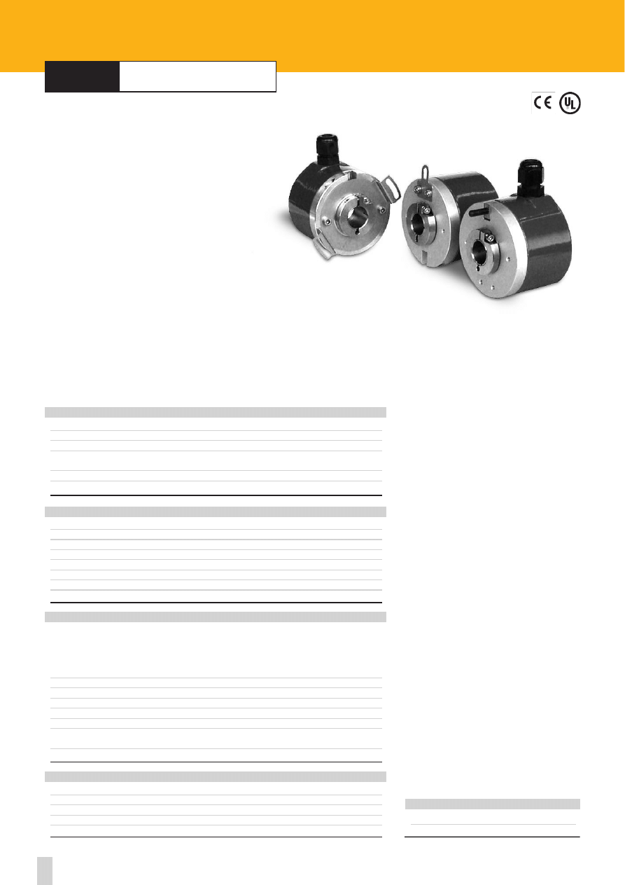
CB50
CB50
Shock:
100 g, 6 ms (acc. to MIL STD 202F)
Vibrations:
10 g, 5-2000 Hz (acc. to MIL STD 202F)
Operating temperature range:
-20°C +100°C (-4°F + 212°F)
Storage temperature range:
-25°C+100°C (-13°F + 212°F)
(98% R.H.without condensation)
Protection:
IP20
ENVIRONMENTAL SPECIFICATIONS
Flange:
non corroding
Housing:
plastic
Bearings:
ABEC 5
Shaft:
stainless steel, non-magnetic
Light source:
GaAl diodes
MATERIALS
Dimension:
see drawing
Shaft hollow:
Ø 6, 6.35, 8, 9.52, 10 mm
Shaft loading (axial and radial):
20 N max.
Shaft rotational speed:
6000 rpm
Weight:
0,1 Kg (3,5 oz)
Starting torque at 20°C
0,8 Ncm (typical)
Moment of inertia
~20 gcm
2
Misalignment
+- 0,3 mm axial
+- 0,06 mm radial
+- 0,2° mm angular
Bearings life:
2x10
9
rev/min.
Weight:
~ 0,1 Kg (3,5 oz)
MECHANICAL SPECIFICATIONS
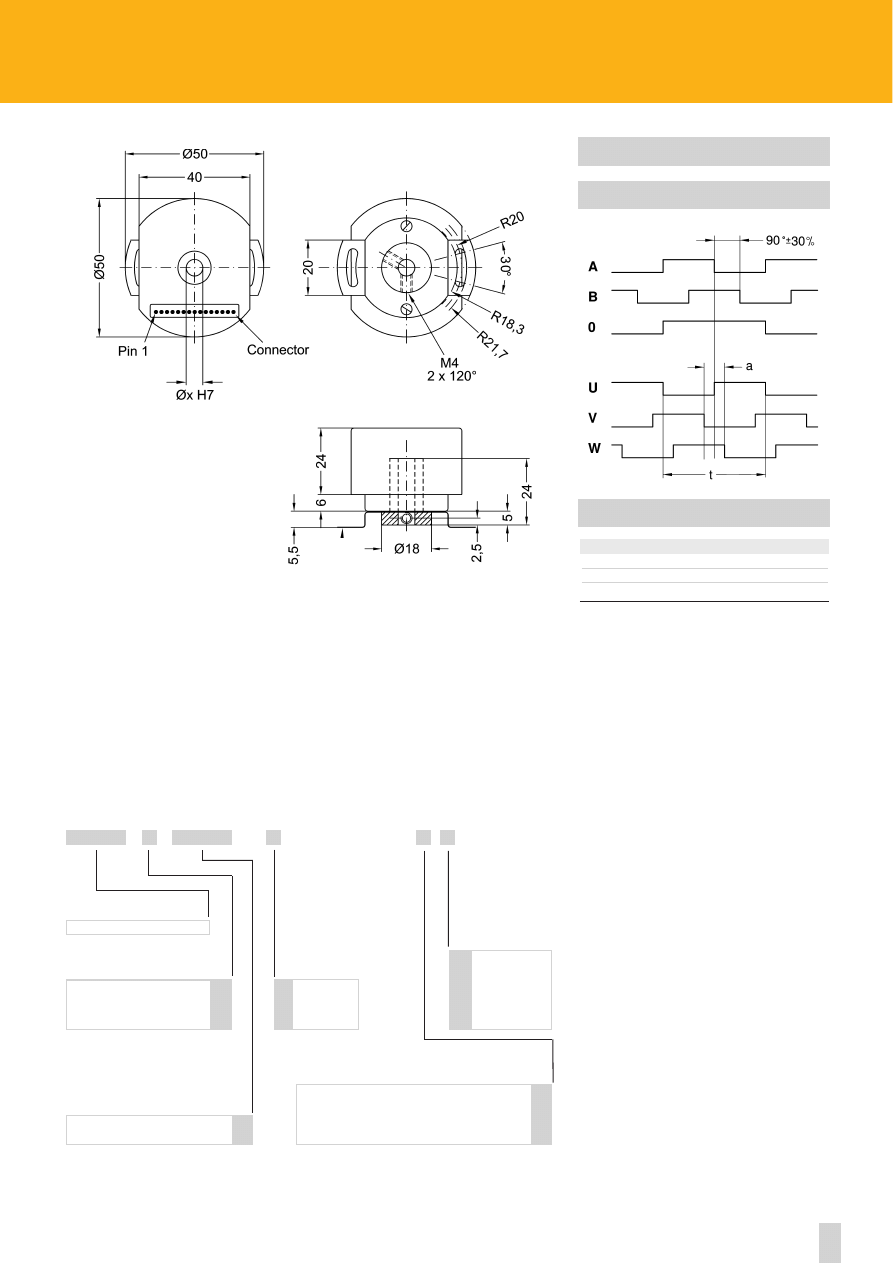
With U, V, W commutations signals
4 - 6 - 8 poles
Power supply:
+5V ±5%, +10V +30V,+5V +30V
Output circuits:
Push-Pull, Line Driver, PP/LD
Output current (per channel):
40 mA max.
Input current:
70 mA max.
Frequency response:
200 kHz max.
Protection:
against inversion of polarity (except +5Vdc version)
outputs are protected against short-circuit (except Line Driver version)
Optoelectronic life:
100.000 hrs min.
Pulse rate - Poles
(other PPR upon request):
ELECTRICAL SPECIFICATIONS
1024/8-2000/4-2000/6-2048/6-2048/8-2500/8
ELECTRICAL CONNECTIONS
15 pin PCB connector
1
0 Vdc 9
U
2
+ Vdc 10
V
3
A 11
W
4
B 12
/U
5
0 13
/V
6
/A 14
/W
7
/B 15
CASE
8
/0
ROTAPULS
Feedback encoders for brushless motors
ACCESSORIES
EC-CB50: mating connector with cable (30 cm/11.8 in.)
22
www.lika.biz
See electrical specifications
CB50
6 mm
6.35 mm / 1/4”
8 mm
9.52 mm / 3/8”
10 mm
6
6.35
8
9.52
10
SERIES
PULSE RATE (PPR)
SHAFT DIAMETER
ORDERING CODE
X
X
X
XXXX
X
XXXX
-
-
Push-Pull
Line Driver AD26LS31 or eqv.
PP/LD universal circuit
Y
L
H
OUTPUT CIRCUITS
/
4 poles
6 poles
8 poles
4
6
8
N° POLES
+5V±5% (L output circuit)
+10V÷ +30V (Y output circuit)
+5V÷ +30V (PP/LD universal circuit)
1
2
4
SUPPLY VOLTAGE VS OUTPUT CIRCUIT
OUTPUT PHASE SHIFT
MECHANICAL ANGLES
N° of poles
a
t
4
30° +- 1°
180°
6
20° +- 1°
120°
8
15° +- 1°
90°
CCW ROTATION (seen from shaft side)
CB50
23
Specifications subject to changes without prior notice
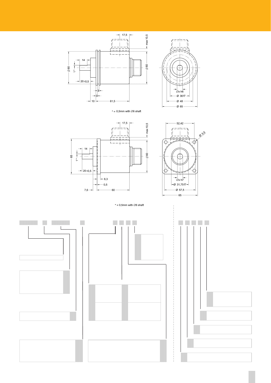
series
C58
•
C59
•
C60
Shock:
100 g, 6 ms (acc. to MIL STD 202F)
Vibrations:
10 g, 5-2000 Hz (acc. to MIL STD 202F)
Operating temperature range:
-20°C +70°C (-4°F +158°F)
Storage temperature range:
-20°C +80°C (-4°F +176°F)
(98% R.H.without condensation)
Protection:
IP64
Option:
• IP65 Protection (3000 rpm max, torque 1 Ncm)
ENVIRONMENTAL SPECIFICATIONS
Dimensions:
see drawing
Shaft hollow:
Ø 14, 15 mm
Shaft loading (axial and radial):
30 N max.
Shaft rotational speed:
6000 rpm max.
Starting torque at 20°C:
≤ 1,5 Ncm (typical)
Moment of inertia:
~30 gcm
2
Bearings life:
10
9
rev. min.
Weight:
~ 0,3 kg (10,6 oz)
MECHANICAL SPECIFICATIONS
Power supply:
+5V±5%, +10V +30V,+5V +30V
Output circuits:
Push-Pull, Line Driver, PP/LD
Output current (per channel):
40 mA max.
Output frequency:
60 kHz max.
Input current:
70 mA max.
Protection:
against inversion of polarity (except +5V version)
outputs are protected against short-circuit (except Line Driver version)
Optoelectronic life:
100.000 hrs min.
STD pulse rate:
(other PPR upon request)
ELECTRICAL SPECIFICATIONS
2-4-5-10-12-15-16-18-20-24-25-30-35-36-39-40
45-50-60-64-70-80-90-100-120-122-125-142
150-180-200-236-250-267-270-300-314-360-400
410-433-435-471-500-600-625-628 635-720-784
800-875 900-946-1000-1024
Flange:
non corroding
Housing:
non corroding
Bearings:
ABEC 5
Shaft:
stainless steel, non-magnetic
Light source:
GaAl diodes
MATERIALS
ROTAPULS
Incremental Encoders
ACCESSORIES
EDE9S:
9 pin DSub mating connector
BR1: Reducing
sleeves
C58-C59-C60
C58 - C59* - C60*
24
www.lika.biz
C58
IP65 Protection
Cable length on request
Ex.: L4 = 4 meters (13.2 ft)
L7 = 7 meters (23.0 ft)
Lx
P
Inline connector DSub 9 pin
C
X X X
Bidirectional
Bidirectional with index pulse
See electrical specifications
Push-Pull
Line Driver AD26LS31 or eqv.
PP/LD universal circuit
+5V±5% (L output circuit)
+10V÷ +30V (Y output circuits)
+5V÷ +30V (PP/LD universal circuit)
Y
L
H
B
Z
1
2
4
14 mm
15 mm
14
15
SERIES
OUTPUT CIRCUITS
PULSE RATE (PPR)
OUTPUT SIGNALS CONFIGURATION
SHAFT DIAMETER
SUPPLY VOLTAGE VS OUTPUT CIRCUIT
XXXX
X
X
X X X
X
ORDERING CODE
XXXX
-
-
ADDITIONAL CODE (indicate only if necessary)
5 wires cable, 1m. (3.3 ft)
8 wires cable, 1m. (3.3 ft)
Normal output
Complementary
outputs
ELECTRICAL CONNECTIONS
N
C
F
U
Reducing sleeves
see on page 75
* Dimensional drawing on page 65
25
Specifications subject to changes without prior notice
series
C58A
•
C58R
Shock:
100 g, 6 ms (acc. to MIL STD 202F)
Vibrations:
10 g, 5-2000 Hz (acc. to MIL STD 202F)
Operating temperature range:
-20°C+70°C (-4°F +158°F)
Storage temperature range:
-20°C +80°C (-4°F +176°F)
(98% R.H.without condensation)
Protection:
IP64
Options:
• IP65 Protection (3000 rpm max, torque 1 Ncm)
ENVIRONMENTAL SPECIFICATIONS
Dimensions:
see drawing
Shaft hollow:
Ø 14, 15 mm
Shaft loading (axial and radial):
30 N max
Shaft rotational speed:
6000 rpm max
Starting torque at 20°C:
≤ 1,5 Ncm (typical)
Moment of inertia:
~30 gcm
2
Bearings life:
10
9
rev. min.
Weight:
~ 0,4 kg (14,1 oz)
MECHANICAL SPECIFICATIONS
Power supply:
+5V±5%, +10V +30V,+5V +30V
Output circuits:
Push-Pull, Line Driver, PP/LD
Output current (per channel):
40 mA max.
Output frequency:
100 kHz max.
Input current:
70 mA max.
Protection:
against inversion of polarity (except +5V version)
outputs are protected against short-circuit (except Line Driver version)
Optoelectronic life:
100.000 hrs min.
Option:
output freq. up to 300 KHz
STD pulse rate
(other PPR upon request):
ELECTRICAL SPECIFICATIONS
6-10-12-15-25-36-40-45-50-60-80-90-100-180
200-250-256-300-360-400-500-512-900-1000
1024-1500-2000-2048-2500
Flange:
non corroding
Housing:
non corroding
Bearings:
ABEC 5
Shaft:
stainless steel, non-magnetic
Light source:
GaAl diodes
MATERIALS
ROTAPULS
Incrementals Encoders
ACCESSORIES
EDE9S:
9 pin DSub mating connector
BR1: Reducing
sleeves
C58A - C58R
26
www.lika.biz
IP65 Protection
Cable length on request
Ex.: L4 = 4 m (13.2 ft)
L7 = 7 m (23.0 ft)
Lx
P
Output frequency up to 300 KHz
W
Inline connector DSub 9 pin
C
X X X X X
Bidirectional
Bidirectional with index pulse
See electrical specifications
Push-Pull
Line Driver AD26LS31 or eqv.
PP/LD universal circuit
C58A - C58R
+5V±5% (L output circuit)
+10V÷ +30V (Y output circuits)
+5V÷+30V (PP/LD universal circuit)
Y
L
H
B
Z
1
2
4
14 mm
15 mm
14
15
SERIES
OUTPUT CIRCUITS
PULSE RATE (PPR)
OUTPUT SIGNALS CONFIGURATION
SHAFT DIAMETER
SUPPLY VOLTAGE VS OUTPUT CIRCUIT
XXXX
X
X
X X X
X
ORDERING CODE
XXXX
-
-
ADDITIONAL CODE (indicate only if necessary)
5 wires cable, 1m. (3.3 ft)
8 wires cable, 1m. (3.3 ft)
Normal output
Complementary
outputs
ELECTRICAL CONNECTIONS
N
C
F
U
Reducing sleeves
see on page 75
see on page 59-60
Operating temperature range:
-40°C + 100°C (-40°F +212°F)
K
C58R
C58A
27
Specifications subject to changes without prior notice
series
CK58
•
CK59
•
CK60
CK58-CK59-CK60
Shock:
100 g, 6 ms (acc. to MIL STD 202F)
Vibrations:
10 g, 5-2000 Hz (acc. to MIL STD 202F)
Operating temperature range:
-20°C+70°C (-4°F +158°F)
Storage temperature range:
-20°C+80°C (-4°F +176°F)
(98% R.H.without condensation)
Protection:
IP64
Options:
• Operating temperature range: -40°C +100°C (-40°F +212°F)
• IP65 Protection (3000 rpm max, torque 1 Ncm)
ENVIRONMENTAL SPECIFICATIONS
Dimensions:
see drawing
Shaft hollow:
Ø 14, 15 mm
Shaft loading (axial and radial):
30 N max.
Shaft rotational speed:
6000 rpm max.
Starting torque at 20°C:
≤ 1,5 Ncm (typical)
Moment of inertia:
~30 gcm
2
Bearings life:
10
9
rev. min.
Weight:
~ 0,4 kg (14,1 oz)
MECHANICAL SPECIFICATIONS
Power supply:
+5V±5%, +10V +30V,+5V +30V
Output circuits:
NPN o.c., PNP o.c., Push-Pull, Line Driver, PP/LD
Output current (per channel):
40 mA max.
Output frequency:
100 kHz max.
Input current:
70 mA max.
Protection:
against inversion of polarity (except +5V version)
outputs are protected against short-circuit (except Line Driver version)
Optoelectronic life:
100.000 hrs min.
Option:
• Output frequency up to 300 kHz max.
STD pulse rate
(other PPR upon request):
ELECTRICAL SPECIFICATIONS
2-4-5-6-10-12-15-16-18-20-24-25-30-35-36-39
4 0 - 4 5 - 5 0 - 6 0 - 6 4 - 7 0 - 8 0 - 9 0 - 1 0 0 - 1 2 0 - 1 2 2
125-127-142-150-180-200-216-236-240-250
254-256-267-270-300-314-360-375-400-410
433-435-471-500-512-600-625-628-635-720
750-784-800-875-900-946-1000-1024-1068
1099-1200-1250-1270-1440-1500-1800-2000
2048-2250-2400-2500-3000-3600-4000-4096
5000-6000-9000-10000
Flange:
non corroding
Housing:
non corroding
Bearings:
ABEC 5
Shaft:
stainless steel, non-magnetic
Light source:
GaAl diodes
MATERIALS
ROTAPULS
Incrementals Encoders
ACCESSORIES
E7MLS:
7 pin MIL mating connector
E10MLS:
10 pin MIL mating connector
EDE9S:
9 pin DSub mating connector
BR1: Reducing
sleeves
Side mount cable or connector
28
www.lika.biz
CK58
Bidirectional
Bidirectional with index pulse
See electrical specifications
NPN o.c.
PNP o.c.
Push-Pull
Line Driver AD26LS31 or eqv.
PP/LD universal circuit
CK58 - CK59* - CK60*
IP65 Protection
Cable length on request
Ex.: L4 = 4 meters (13.2 ft)
L7 = 7 meters (23.0 ft)
Operating temperature range:
-40°C + 100°C (-40°F +212°F)
+5V±5% (L output circuit)
+10V÷ +30V (N, P and Y output circuits)
+5V÷ +30V (PP/LD universal circuit)
N
P
Y
L
H
R
Lx
P
K
B
Z
1
2
4
SERIES
OUTPUT CIRCUITS
PULSE RATE (PPR)
OUTPUT SIGNALS CONFIGURATION
SUPPLY VOLTAGE VS OUTPUT CIRCUIT
XXXX
X
X
X X X X X X
X X X
X
ORDERING CODE
Output frequency up to 300 kHz
W
Inline connector DSub 9 pin
C
XXXX
-
-
ADDITIONAL CODE (indicate only if necessary)
5 wires cable, 1m. (3.3 ft)
7 pin IP65 MIL connector
8 wires cable, 1m. (3.3 ft)
10 pin IP65 MIL connector
Normal output
Complementary
outputs
ELECTRICAL CONNECTIONS
N
C
F
D
U
P
(1) Mechanical dimensions with connector output see on page 64
14 mm
15 mm
14
15
SHAFT DIAMETER
Reducing sleeves
see on page 75
see on page 59-60
* Dimensional drawing on page 75
(1)
29
Specifications subject to changes without prior notice
series
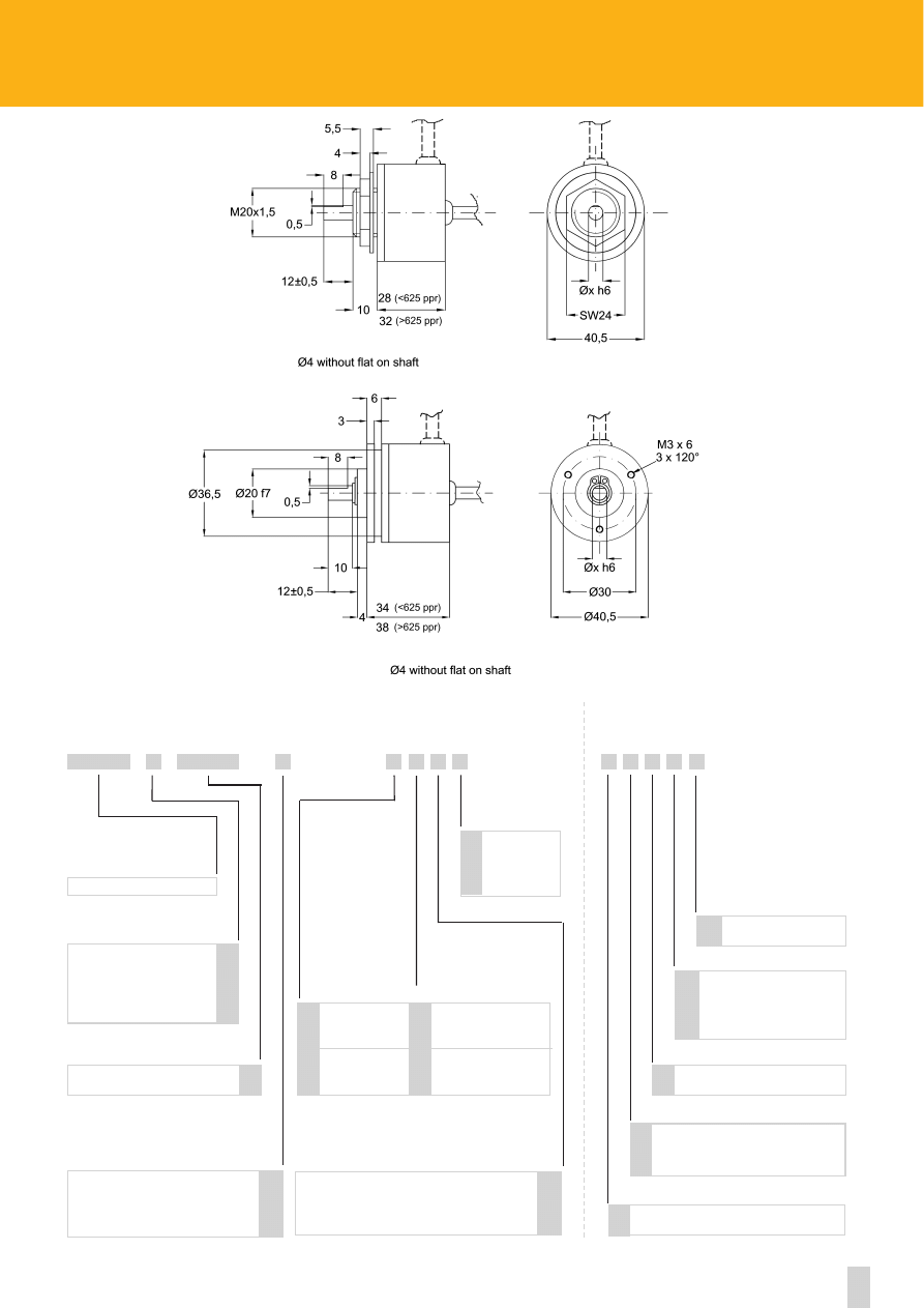
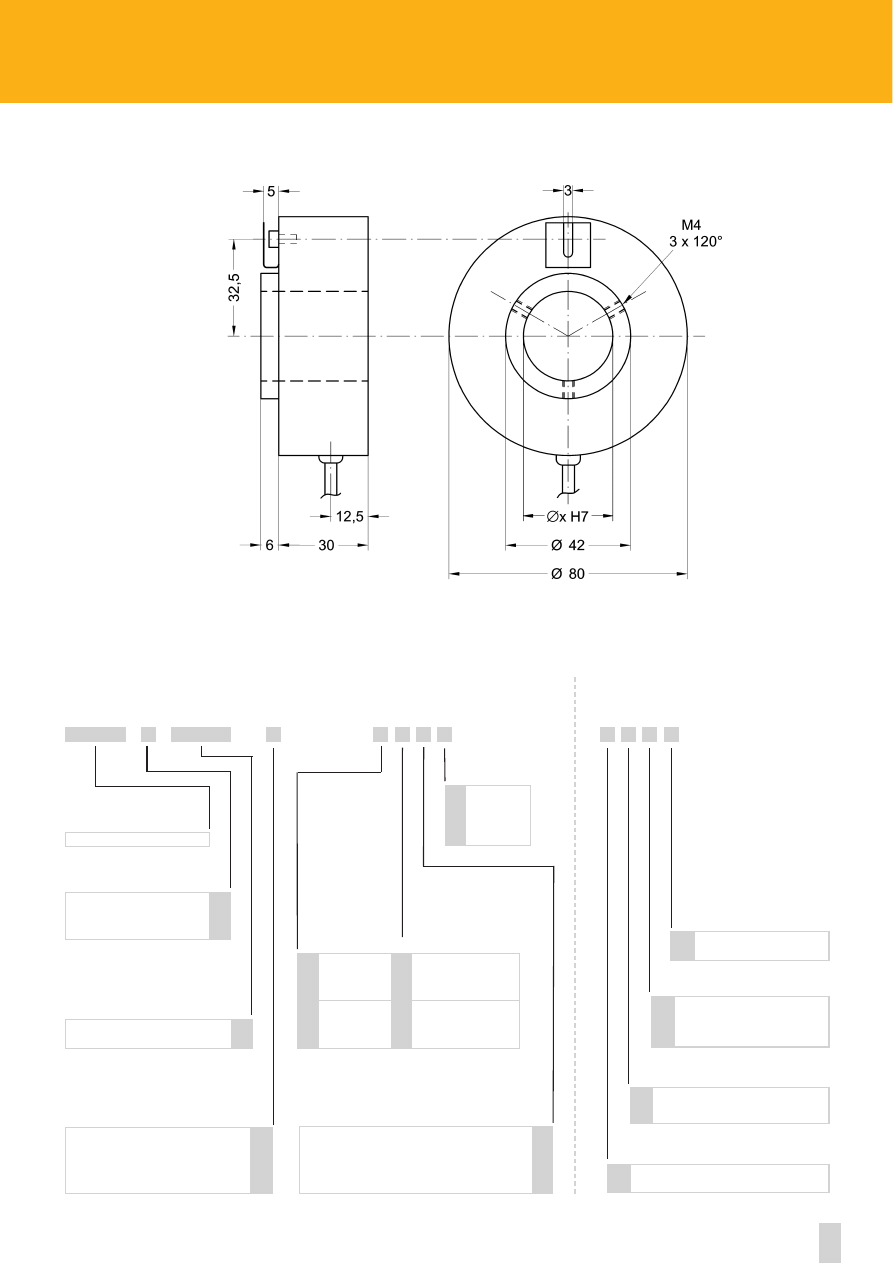
C80
C80
Shock:
100 g, 6 ms (acc. to MIL STD 202F)
Vibrations:
10 g, 5-2000 Hz (acc. to MIL STD 202F)
Operating temperature range:
-20°C +70°C (-4°F +158°F)
Storage temperature range:
-20°C +80°C (-4°F +176°F)
(98% R.H.without condensation)
Protection:
IP64
Options:
• Operating temperature range: -40°C +100°C (-40°F +212°F)
• IP65 Protection (3000 rpm max, torque 2 Ncm)
ENVIRONMENTAL SPECIFICATIONS
Dimensions:
see drawing
Shaft hollow:
Ø 6 ÷ 30 mm
Shaft loading (axial and radial):
30 N max.
Shaft rotational speed:
6000 rpm max.
Starting torque at 20°C:
≤ 1,5 Ncm (typical)
Moment of inertia:
~30 gcm
2
Bearings life:
10
9
rev. min.
Weight:
~ 0,4 kg (14,1 oz)
MECHANICAL SPECIFICATIONS
Power supply:
+5V±5%, +10V +30V,+5V +30V
Output circuits:
Push-Pull, Line Driver, PP/LD
Output current (per channel):
40 mA max.
Output frequency:
100 kHz max.
Input current:
70 mA max.
Protection:
against inversion of polarity (except +5V version)
outputs are protected against short-circuit (except Line Driver version)
Optoelectronic life:
100.000 hrs min.
STD pulse rate:
(other PPR upon request)
ELECTRICAL SPECIFICATIONS
12-100-200-360-400-500-1000-1024-2000-2048
(2000 and 2048 without index pulse
)
Flange:
non corroding
Housing:
non corroding
Bearings:
ABEC 5
Shaft:
stainless steel, non-magnetic
Light source:
GaAl diodes
MATERIALS
ROTAPULS
Incrementals Encoders
ACCESSORIES
EDE9S:
9 pin DSub mating connector
30
www.lika.biz
C80
IP65 Protection
Cable length on request
Ex.: L4 = 4 m (13.2 ft)
L7 = 7 m (23.0 ft)
Operating temperature range:
-40°C + 100°C (-40°F +212°F)
Lx
P
K
Inline connector DSub 9 pin
C
X X X X
Bidirectional
Bidirectional with index pulse
See electrical specifications
Push-Pull
Line Driver AD26LS31 or eqv.
PP/LD universal circuit
C80
+5V±5% (L output circuit)
+10V÷ +30V (Y output circuit)
+5V÷ +30V (PP/LD universal circuit)
Y
L
H
B
Z
1
2
4
6 mm
...
30 mm
6
...
30
SERIES
OUTPUT CIRCUITS
PULSE RATE (PPR)
OUTPUT SIGNALS CONFIGURATION
SHAFT DIAMETER
SUPPLY VOLTAGE VS OUTPUT CIRCUIT
XXXX
X
X
X X X
X
ORDERING CODE
XXXX
-
-
ADDITIONAL CODE (indicate only if necessary)
5 wires cable, 1m. (3.3 ft)
8 wires cable, 1m. (3.3 ft)
Normal output
Complementary
outputs
ELECTRICAL CONNECTIONS
N
C
F
U
see on page 59-60
31
Specifications subject to changes without prior notice
series
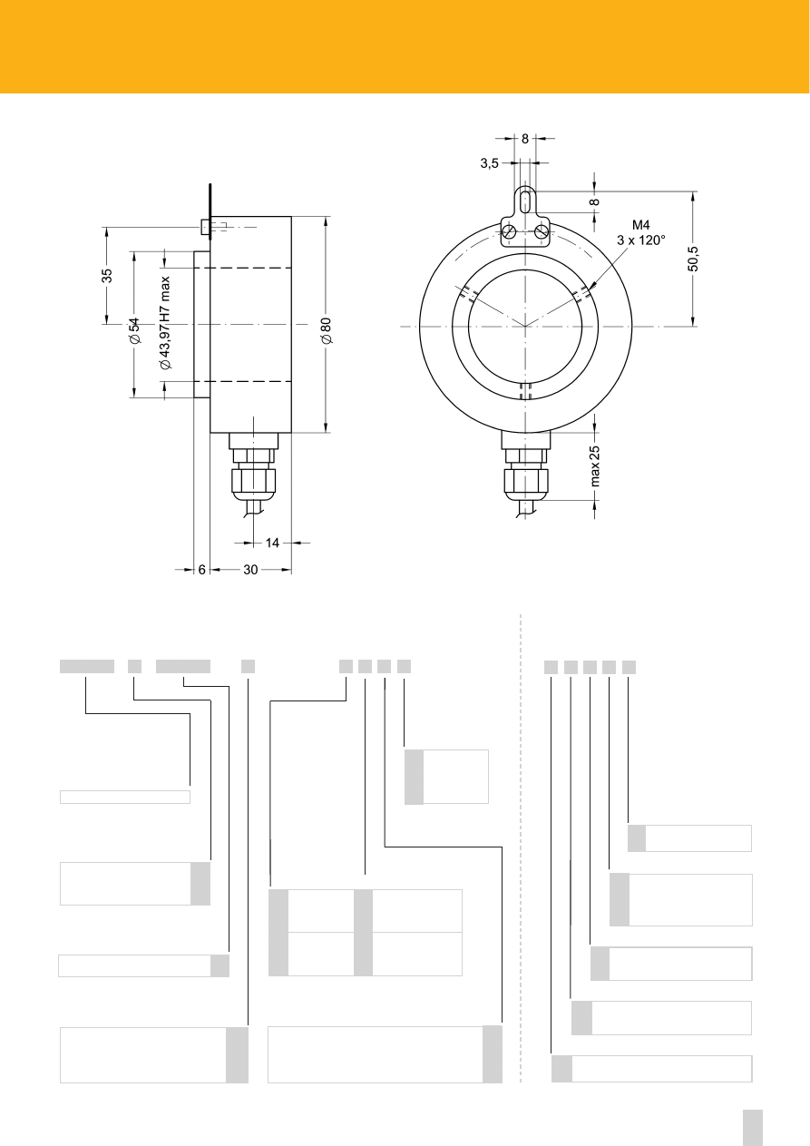
C81
C81
Shock:
100 g, 6 ms (acc. to MIL STD 202F)
Vibrations:
10 g, 5-2000 Hz (acc. to MIL STD 202F)
Operating temperature range:
-20°C +70°C (-4°F +158°F)
Storage temperature range:
-20°C +80°C (-4°F +176°F)
(98% R.H.without condensation)
Protection:
IP54
Options:
• Operating temperature range: -40°C +100°C (-40°F +212°F)
• IP65 Protection (2000 rpm max, torque 2 Ncm)
ENVIRONMENTAL SPECIFICATIONS
Dimensions:
see drawing
Shaft hollow:
Ø 20 ÷ 43,97 mm
Shaft loading (axial and radial):
60 N max.
Shaft rotational speed:
2000 rpm@70°C (158°F)/IP54
3000 rpm@100°C (212°F)/IP54
1500 rpm@70°C (158°F)/IP65
2000 rpm@100°C (212°F)/IP65
Starting torque at 20°C:
4 ÷12 Ncm (typical)
Moment of inertia:
100 ÷ 450 gcm
2
Misalignment:
± 0,3 mm radial
± 0,2 mm axial
Bearings life:
10
9
rev. min.
Weight:
0,3 ÷ 0,6 kg (10,6-21,2 oz)
MECHANICAL SPECIFICATIONS
Power supply:
+5V±5%, +10V +30V,+5V +30V
Output circuits:
Push-Pull, Line Driver, PP/LD
Output current (per channel):
40 mA max.
Output frequency:
100 kHz max.
Input current:
40 mA max.
Protection:
against inversion of polarity (except +5V version)
outputs are protected against short-circuit (except Line Driver version)
Optoelectronic life:
100.000 hrs min.
Option:
• Output freq. 200 kHz max.
STD pulse rate
12-300-500-1024-2000-2048-2500
(other PPR upon request):
ELECTRICAL SPECIFICATIONS
Flange:
steel
Housing:
non corroding
Bearings:
ABEC 5
Shaft:
stainless steel, non-magnetic
Light source:
GaAl diodes
MATERIALS
ROTAPULS
Incremental Encoders
ACCESSORIES
EDE9S:
9 pin DSub mating connector
32
www.lika.biz
C81
Inline connector DSub 9 pin
C
Bidirectional
Bidirectional with index pulse
See electrical specifications
Push-Pull
Line Driver AD26LS31 or eqv.
PP/LD universal circuit
C81
+5V±5% (L output circuit)
+10V÷ +30V (Y output circuits)
+5V÷+30V (PP/LD universal circuit)
Y
L
H
B
Z
1
2
4
20 mm
...
43,97 mm
20
...
44
SERIES
OUTPUT CIRCUITS
PULSE RATE (PPR)
OUTPUT SIGNALS CONFIGURATION
SHAFT DIAMETER
SUPPLY VOLTAGE VS OUTPUT CIRCUIT
XXXX
X
X
X X X
X
ORDERING CODE
XXXX
-
-
ADDITIONAL CODE (indicate only if necessary)
5 wires cable, 1m. (3.3 ft)
8 wires cable, 1m. (3.3 ft)
Normal output
Complementary
outputs
ELECTRICAL CONNECTIONS
N
C
F
U
see on page 59-60
IP65 Protection
P
X X
X X
Output frequency up to 200 kHz
W
X
Operating temperature range:
-40°C + 100°C (-40°F +212°F)
K
Cable length on request
Ex.: L4 = 4 m. (13.2 ft)
L7 = 7 m. (23.0 ft)
Lx

33
Specifications subject to changes without prior notice
ROTACOD
Absolute single turn encoders
series
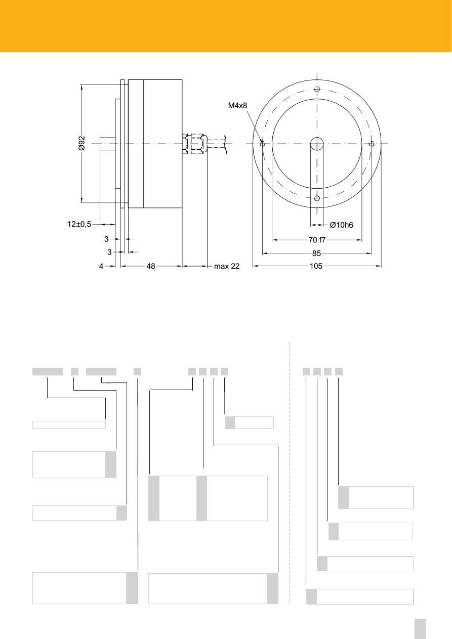
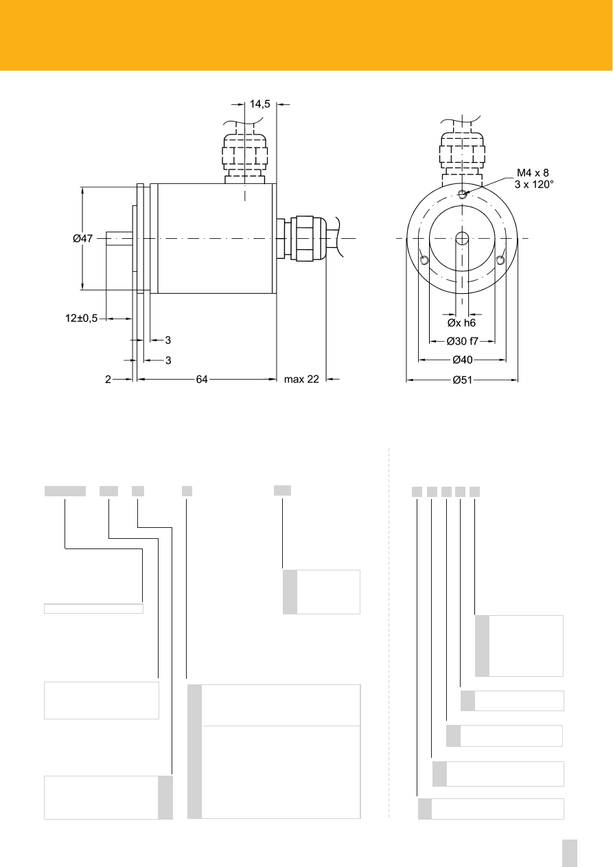
AS5
AS5
Shock:
100 g, 6 ms (acc. to MIL STD 202F)
Vibrations:
10 g, 5-2000 Hz (acc. to MIL STD 202F)
Operating temperature range:
-20°C +70°C (-4°F +158°F)
Storage temperature range:
-20°C +80°C (-4°F +176°F)
(98% R.H.without condensation)
Protection:
IP65
Option:
• Operating temperature range: -40°C +100°C (-40°F +212°F)
ENVIRONMENTAL SPECIFICATIONS
STD codes
Gray, Binary
Power supply:
+10V +30V
Power consumption:
1,2 W
Output circuits:
NPN o.c., PNP o.c., Push-Pull
Output current:
40 mA max.
Output frequency:
60 kHz max.
Accuracy:
± 40% LSB
Protection:
Protected against inversion of polarity, Push-Pull protected against short-circuit
Optoelectronic life:
100.000 h min.
Options:
• LATCH output
• TRI-STATE output
• Electronic parity bit
ELECTRICAL SPECIFICATIONS
Housing:
non corroding
Flange:
non corroding
Bearings:
ABEC 5
Shaft:
stainless steel, non-magnetic
Light source:
GaAI diodes
MATERIALS
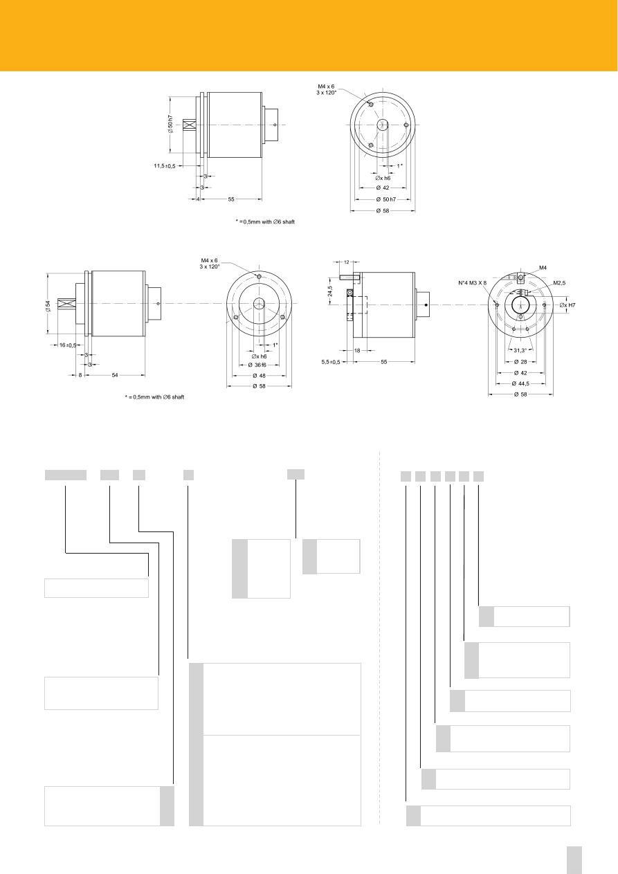
Dimensions:
see drawing
Shaft:
Ø 6, 8, 10, 12 mm
Shaft loading (axial and radial):
40 N max.
Shaft rotational speed:
6000 rpm max.
Moment of inertia:
~80 gcm
2
Bearing life:
400x10
6
rev. min. (10
9
rev. min. with shaft loading of 20 N max.)
Weight:
~0,3 kg (10,6 oz)
Electrical connections:
16 wires cable, 1 m. (3.3 ft)
Option:
• Inline connector EDA 15P, EDB 25P, ES19MLPV
MECHANICAL SPECIFICATIONS
ACCESSORIES
E19MLS:
19 pin MIL mating connector
EDB 25S:
25 pin DSub mating connector
EDA 15S:
15 pin DSub mating connector
PAN/PGF:
flexible couplings
LKM-386:
fixing clamps
Side mount cable
34
www.lika.biz
AS5
Binary
Gray
AS5
B
G
6 mm
8 mm
10 mm
12 mm
6
8
10
12
SERIES
OUTPUT CODE
SHAFT DIAMETER
ORDERING CODE
X
XX
X
XX
XXX
/
-
-
Parity Bit
Operating temperature range:
-40°C + 100°C (-40°F +212°F)
R
B
K
ADDITIONAL CODE (indicate only if necessary)
Cable length on request
Lx
X X X X X
Counts per revolution
1 - 2048
(see on page 66)
CODE
NPN o.c.
PNP o.c.
Push-Pull
on request
LATCH (NPN)
LATCH (PNP)
LATCH (Push-Pull)
TRI-STATE (NPN)
TRI-STATE (PNP)
LATCH+TRI-STATE (PNP)
LATCH+TRI-STATE (NPN)
N
P
Y
L
M
H
T
U
E
F
OUTPUT CIRCUITS
EDA 15P inline connector
EDB 25P inline connector
ES19MLPV inline connector
Z
W
P
35
Specifications subject to changes without prior notice
ROTACOD
Absolute single turn encoders
series
AS58
•
AS58S
•
ASC58
Shock:
100 g, 6 ms (acc. to MIL STD 202F)
Vibrations:
10 g, 5-2000 Hz (acc. to MIL STD 202F)
Operating temperature range:
-20°C +70°C (-4°F +158°F)
Storage temperature range:
-20°C +80°C (-4°F +176°F)
(98% R.H.without condensation)
Protection:
IP65
Option:
• Operating temperature range: -40°C +100°C (-40°F +212°F)
ENVIRONMENTAL SPECIFICATIONS
STD codes
Gray, Binary
Power supply:
+10V +30V
Power consumption:
1,2 W
Output circuits:
NPN o.c., PNP o.c., Push-Pull, SSI
Output current:
40 mA max.
Output frequency:
60 kHz max.
Accuracy:
± 30% LSB
Protection:
Protected against inversion of polarity, Push-Pull protected against short-circuit.
Optoelectronic life:
100.000 h min.
Options:
• LATCH output
• TRI-STATE output
• Electronic parity bit
• Electronic zero setting
ELECTRICAL SPECIFICATIONS
Housing:
non corroding
Flange:
non corroding
Bearings:
ABEC 5
Shaft:
stainless steel, non-magnetic
Light source:
GaAI diodes
MATERIALS
Dimensions:
see drawing
Shaft:
Ø 6, 8, 9.52, 10, 12, 14, 15 mm
Shaft loading (axial and radial):
40 N max.
Shaft rotational speed:
6000 rpm max.
Moment of inertia:
~95 gcm
2
Bearing life:
400x10
6
rev. min. (10
9
rev. min. with shaft loading of 20 N max.)
Weight:
~0,3 kg (10,6 oz)
Electrical connections
(see on page 62)
:
E19MLP, E10MLP, E7MLP MIL connector
Options:
• EDA 15P connector
(see on page 62)
• EDB 25P connector
• cable output 1 m
MECHANICAL SPECIFICATIONS
ACCESSORIES
E19MLS:
19 pin MIL mating connector
E7MLS:
7 pin MIL mating connector
E10MLS:
10 pin MIL mating connector
EDB 25S:
25 pin DSub mating connector
EDA 15S:
15 pin DSub mating connector
PAN/PGF:
flexible couplings
BR1:
reducing sleeves
LKM-386:
fixing clamps
AS58-AS58S-ASC58
Side mount cable or connector
36
www.lika.biz
ASC58
Binary
Gray
AS58 - AS58S - ASC58
ASC59* - ASC60*
B
G
SERIES
OUTPUT CODE
ORDERING CODE
X
X
XX
XXX
/
-
Parity Bit
Operating temperature range:
-40°C + 100°C (-40°F +212°F)
R
B
K
ADDITIONAL CODE (indicate only if necessary)
Cable length on request
Lx
X X X X X X
Counts per revolution
1 - 131072
(see on page 66)
CODE
NPN o.c.
PNP o.c.
Push-Pull
SSI serial output RS422 tree format (connector)
SSI serial output RS422 tree format (cable)
SSI serial output RS422 LSB alligned (connector)
SSI serial output RS422 LSB alligned (cable)
on request
LATCH (NPN)
LATCH (PNP)
LATCH (Push-Pull)
TRI-STATE (NPN)
TRI-STATE (PNP)
LATCH+TRI-STATE (PNP)
LATCH+TRI-STATE (NPN)
N
P
Y
S
R
A
B
L
M
H
T
U
E
F
OUTPUT CIRCUITS
15 pin DSub connector
25 pin DSub connector
Z
W
Electronic zero setting
E
* see notes on pag. 69
6 mm
8 mm
9.52 mm /3/8”
10 mm
12 mm
6
8
9.52
10
12
SHAFT DIAMETER
XX
AS58 - AS58S
AS58
AS58S
-
(1) Mechanical dimensions with
connector output see on page 64
(1)
(1)
(1)
14 mm
15 mm
14
15
SHAFT DIAMETER
Reducing sleeves
see on page 75
ASCxx
* Dimensional drawing on page 65
37
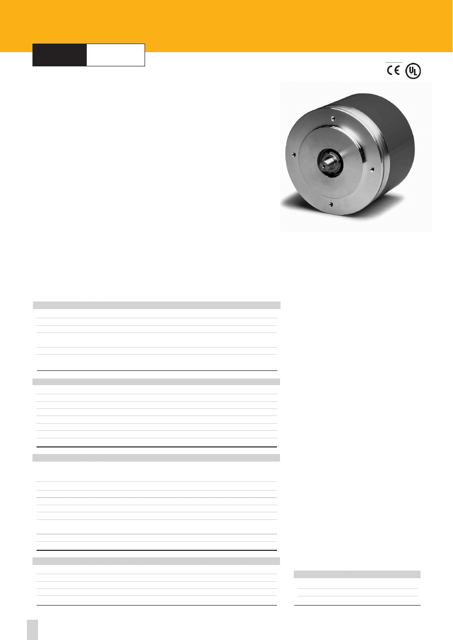
Specifications subject to changes without prior notice
ROTACOD
Absolute single turn encoders
series
AST6
AST6
Shock:
100 g, 6 ms (acc. to MIL STD 202F)
Vibrations:
10 g, 5-2000 Hz (acc. to MIL STD 202F)
Operating temperature range:
-20°C +70°C (-4°F +158°F)
Storage temperature range:
-20°C +80°C (-4°F +176°F)
(98% R.H.without condensation)
Protection:
IP65
Options:
• Operating temperature range: -40°C +100°C (-40°F +212°F)
• IP66 protection shaft side (with IP65 conn.)
ENVIRONMENTAL SPECIFICATIONS
STD codes
Gray, Binary, BCD
Power supply:
+10V +30V
Power consumption:
1,2 W
Output circuits:
NPN o.c., PNP o.c., Push-Pull, SSI
Output current:
40 mA max.
Output frequency:
60 kHz max.
Accuracy:
± 30% LSB
Protection:
Protected against inversion of polarity, Push-Pull protected against short-circuit.
Optoelectronic life:
100.000 h min.
Options:
• LATCH output
• TRI-STATE output
• Electronic parity bit
• Electronic zero setting
ELECTRICAL SPECIFICATIONS
Housing:
non corroding
Flange:
non corroding
Bearings:
ABEC 5
Shaft:
stainless steel, non-magnetic
Light source:
GaAI diodes
MATERIALS
Dimensions:
see drawing
Shaft:
Ø 6, 8, 9.52, 10, 12 mm
Shaft loading (axial and radial):
100 N max.
Shaft rotational speed:
6000 rpm max.
Moment of inertia:
~80 gcm
2
Bearing life:
400x10
6
rev. min. (10
9
rev. min. with shaft loading of 20 N max.)
Weight:
~0,3 kg (10,6 oz)
Electrical connections
(see on page 62)
:
E19MLP, E10MLP, E7MLP MIL connector
Options:
• EDA 15P DSub connector
(see on page 62)
• cable output 1 m
MECHANICAL SPECIFICATIONS
ACCESSORIES
E19MLS:
19 pin MIL mating connector
E7MLS:
7 pin MIL mating connector
E10MLS:
10 pin MIL mating connector
EDA 15S:
15 pin DSub mating connector
PAN/PGF:
flexible couplings
BR1:
reducing sleeves
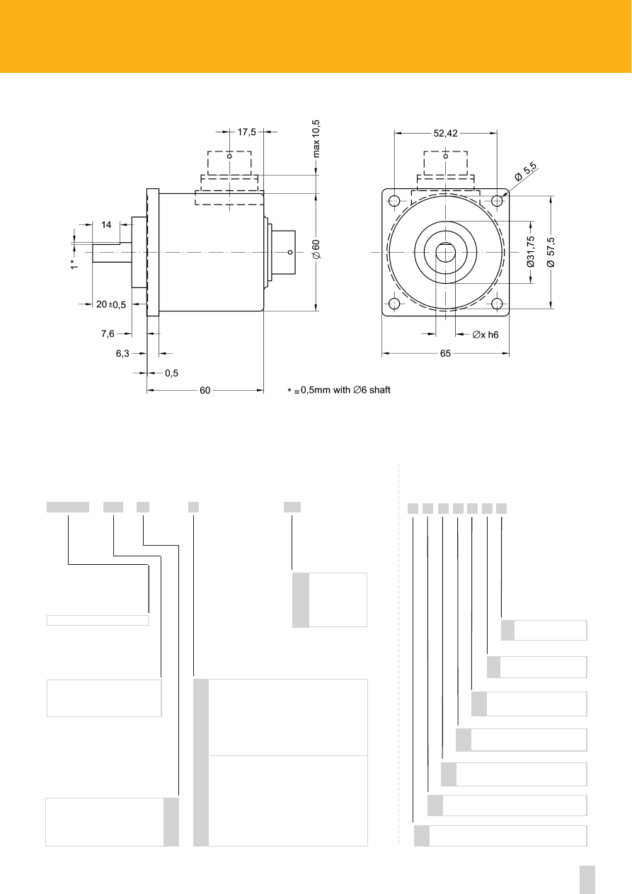
Side mount cable or connector
38
www.lika.biz
AST6
Binary
Gray
BCD
AST6
B
G
D
6 mm
8 mm
9.52 mm / 3/8”
10 mm
12 mm
6
8
9.52
10
12
SERIES
OUTPUT CODE
SHAFT DIAMETER
ORDERING CODE
X
XX
X
XX
XXX
-
-
/
Parity Bit
Operating temperature range:
-40°C + 100°C (-40°F +212°F)
R
B
K
ADDITIONAL CODE (indicate only if necessary)
Cable length on request
Lx
X X X X X X X
Counts per revolution
1 - 131072
(see on page 66)
CODE
15 pin DSub connector
Z
IP66 protection shaft side
Q
Electronic zero setting
E
NPN o.c.
PNP o.c.
Push-Pull
SSI serial output RS422 tree format (connector)
SSI serial output RS422 tree format (cable)
SSI serial output RS422 LSB alligned (connector)
SSI serial output RS422 LSB alligned (cable)
on request
LATCH (NPN)
LATCH (PNP)
LATCH (Push-Pull)
TRI-STATE (NPN)
TRI-STATE (PNP)
LATCH+TRI-STATE (PNP)
LATCH+TRI-STATE (NPN)
N
P
Y
S
R
A
B
L
M
H
T
U
E
F
OUTPUT CIRCUITS
* see notes on pag. 69
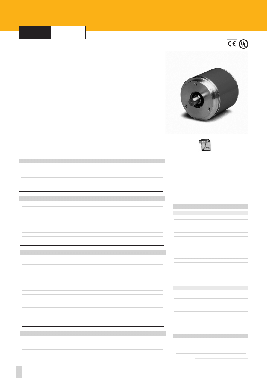
39
Specifications subject to changes without prior notice
ROTACAM
Encoder with integrated cam programmer
series
ASR58
25 pin DSub mating connector
1
OUT1 14
OUT14
2
OUT2 15
OUT15
3
OUT3 16
OUT16
4
OUT4 17
Load Prg
5
OUT5 18
Sel. Prg 2
0
6
OUT6 19
Sel. Prg 2
1
7
OUT7 20
Sel. Prg 2
2
8
OUT8 21
Sel. Prg 2
3
9
OUT9 22
Zero setting
10
OUT10 23
Complementary
11
OUT11 24
+10Vdc +30Vdc
12
OUT12 25
0 Vdc
13
OUT13
ASR58
Shock:
100 g, 6 ms (acc. to MIL STD 202F)
Vibrations:
10 g, 5-2000 Hz (acc. to MIL STD 202F)
Operating temperature range:
-20°C +70°C (-4°F +158°F)
Storage temperature range:
-20°C +80°C (-4°F +176°F)
(98% R.H.without condensation)
Protection:
IP65
ENVIRONMENTAL SPECIFICATIONS
Information/rev.:
3600
Resolution:
0,1°
Nr. of cams per program:
120
Nr. of programs:
16
Power supply:
+10V +30V
Power consumption:
2 W
Output:
Push-Pull
Output current (per channel):
100 mA max.
Output frequency:
100 kHz max.
Cam delay:
1µsec
Supplementary output:
Pulse output for speed testing (LSB Binary)
Fault signal indicating output status
Protection:
Protected against inversion of polarity and short-circuit.
Optoelectronic life:
100.000 h min.
Option:
• Analog output (programmable on output nr.1)
0V +10V , 0V +5V , -5V +5V
ELECTRICAL SPECIFICATIONS
Housing:
non corroding
Flange:
non corroding
Bearings:
ABEC 5
Shaft:
stainless steel, non-magnetic
Light source:
GaAI diodes
MATERIALS
Dimensions:
see drawing
Shaft:
Ø 6, 8, 9.52, 10, 12 mm
Shaft loading (axial and radial):
40 N max.
Shaft rotational speed:
6000 rpm max (up to 6000 rpm for short periods)
Starting torque at 20°C:
< 0,2 Ncm (typical)
Moment of inertia:
~95 gcm
2
Bearing life:
400x10
6
rev. min. (10
9
rev. min. with shaft loading of 20 N max.)
Weight:
~0,3 kg (10,6 oz)
Electrical connections:
EDA 15P and EDB 25P DSub connectors
(see on page 62)
MECHANICAL SPECIFICATIONS
ELECTRICAL CONNECTIONS
15 pin DSub mating connector
1
N.C. 9
N.C.
2
N.C. 10
N.C.
3
N.C. 11
GND
4
Analogue output 12
RXD (RS232)
5
Speed 13
TXD (RS232)
6
GND 14
+10Vdc +30Vdc
7
Fault 15
0 Vdc
8
GND (RS232)
www.lika.biz
- manual
- software
- datasheet
ACCESSORIES
EDB 25S:
25 pin DSub mating connector
EDA 15S:
15 pin DSub mating connector
PAN/PGF:
flexible couplings
LKM-386:
fixing clamps
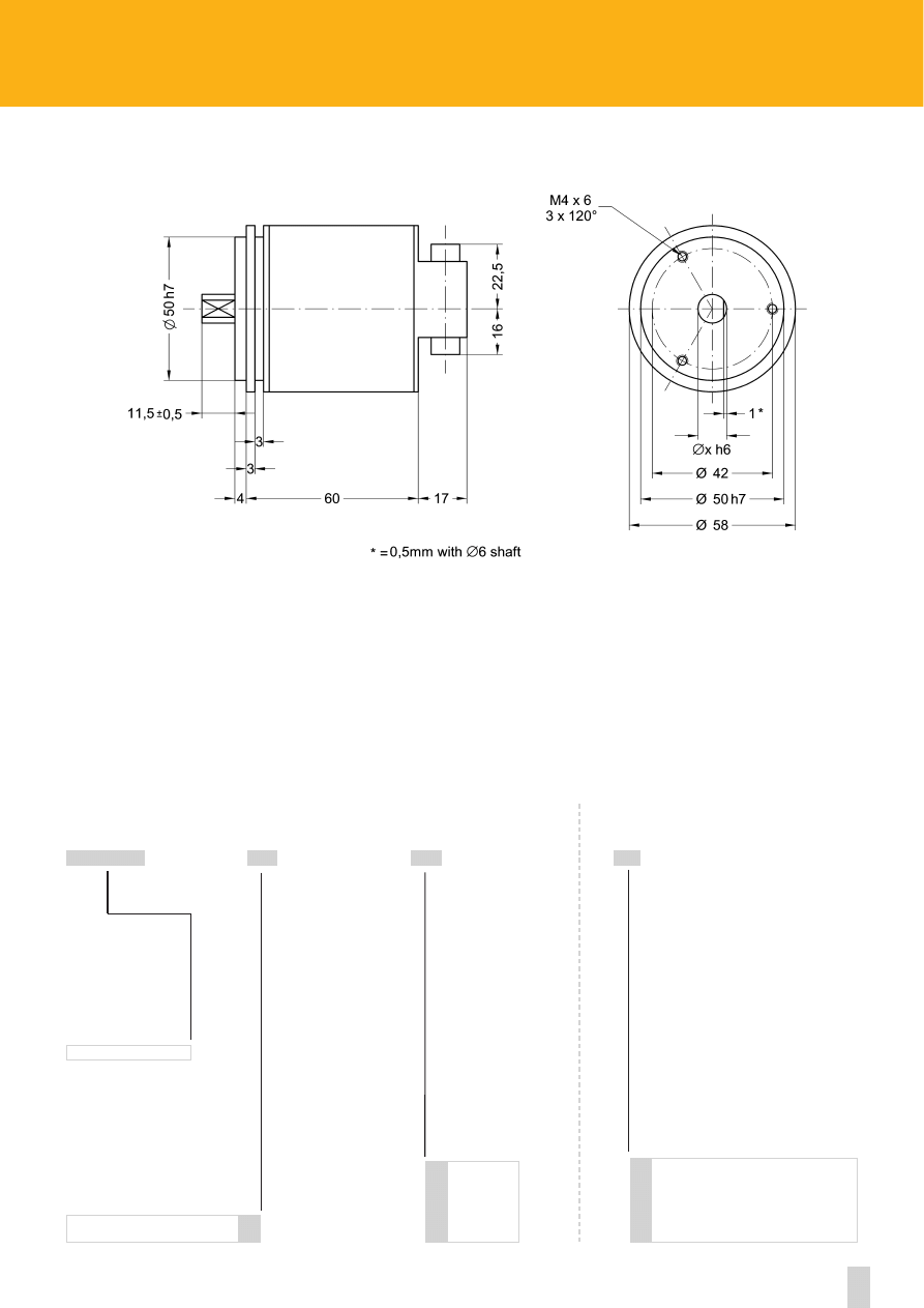
40
www.lika.biz
ASR58
ASR58
6 mm
8 mm
9.52 mm/ 3/8”
10 mm
12 mm
6
8
9.52
10
12
SERIES
SHAFT DIAMETER
ORDERING CODE
X
XX
XXXXX
Analogue output 0-10V
Analogue output 0-5V
Analogue output -5V +5V
A1
A2
A3
ADDITIONAL CODE (indicate only if necessary)
X
3600 CPR 81
COUNTS PER REV.
-
41
Specifications subject to changes without prior notice
ROTACOD
Absolute single turn encoder with analogue output
series
AS58 A
7 pin MIL mating connector
A
- lout (4-20mA) E
Fault
B
+ lout (4-20mA) F
GND
C
Complementary G
+15V +30V
D
Hold
AS58 A
Shock:
100 g, 6 ms (acc. to MIL STD 202F)
Vibrations:
10 g, 5-2000 Hz (acc. to MIL STD 202F)
Operating temperature range:
-20°C +70°C (-4°F +158°F)
Storage temperature range:
-20°C +80°C (-4°F +176°F)
(98% R.H.without condensation)
Protection:
IP65
ENVIRONMENTAL SPECIFICATIONS
Resolution of current analog output AI1 (4-20mA):
3,9 x 10
-6
A
Resolution of voltage analog output AV1 (0-5V):
1,22 x 10
-3
V
Resolution of voltage analog output AV2 (0-10V):
2,44 x 10
-3
V
Power supply:
+15V +30V
Power consumption:
1,2 W
Output frequency:
40 kHz max.
Protection:
against inversion of polarity
Optoelectronic life:
100.000 h min.
ELECTRICAL SPECIFICATIONS
Housing:
non corroding
Flange:
non corroding
Bearings:
ABEC 5
Shaft:
stainless steel, non-magnetic
Light source:
GaAI diodes
MATERIALS
Dimensions:
see drawing
Shaft:
Ø 6, 8, 9.52, 10, 12 mm
Shaft loading (axial and radial):
40 N max.
Shaft rotational speed:
6000 rpm max.
Starting torque at 20°C:
< 1 Ncm (tipico/typical)
Moment of inertia:
~95 gcm
2
Bearing life:
400x10
6
rev. min. (10
9
rev. min. with shaft loading of 20 N max.)
Weight:
~ 0,3 kg (10,6 oz)
Electrical connections
(see on page 62)
:
E7MLP MIL connector
MECHANICAL SPECIFICATIONS
ELECTRICAL CONNECTIONS
with analog output AI1
with analog output AV1, AV2
7 pin MIL mating connector
A
GND E
n.c.
B
+ Vout F
GND
C
Complementary G
+15V +30V
D
Hold
ACCESSORIES
E7MLS:
7 pin MIL mating connector
PAN/PGF:
flexible couplings
LKM-386:
fixing clamps
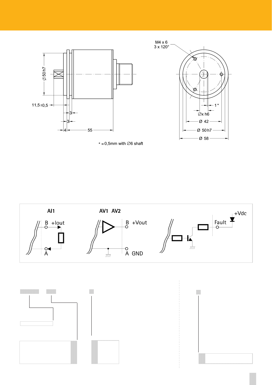
Side mount connector
42
AS58 A
AS5812
6 mm
8 mm
9.52 mm/ 3/8”
10 mm
12 mm
6
8
9.52
10
12
SERIES
SHAFT DIAMETER
ORDERING CODE
X
XXX
XXXXXX
/
R
X
ADDITIONAL CODE (indicate only if necessary)
Current analog output (4-20mA)
Voltage analog output (0-5V)
Voltage analog output (0-10V)
OUTPUT CIRCUITS
AI1
AV1
AV2
-
-
Description:
Output AI1: Quote 0 = 4mA, Quote 4095 = 20mA
Output AV1: Quote 0 = 0V, Quote 4095 = 5V
Output AV2: Quote 0 = 0V, Quote 4095 = 10V
”-lout“ signal is internally connected to GND.
Hold = Data latch in memory (active high +10V +30V).
Fault = Open collector signal (i.e. to be connected to a LED see fig.1) for cable integrity check (only AI1 output).
figura 1/figure1
(1) Mechanical dimensions with connector output see on page. 64
(1)
www.lika.biz

43
Specifications subject to changes without prior notice
ROTACOD
Absolute encoder with incremental serial interface
series
Ax58 ISI
12 pin IP65 mating connector
1
A 7
n.c.
2
/A 8
Error output
3
B 9
Zero setting
4
/B 10
Complementary
5
0 11
+10Vdc +30Vdc
6
/0 12
0 Vdc
AS58 ISI
Shock:
100 g, 6 ms (acc. to MIL STD 202F)
Vibrations:
10 g, 5-2000 Hz (acc. to MIL STD 202F)
Operating temperature range:
-20°C +70°C (-4°F +158°F)
Storage temperature range:
-20°C +80°C (-4°F +176°F)
(98% R.H.without condensation)
Protection:
IP65
ENVIRONMENTAL SPECIFICATIONS
STD pulse rate (other PPR upon request):
720 - 1024 - 2048
Power supply:
+10V +30V
Input current:
250 mA max.
Output current (per channel):
40 mA max.
Output frequency:
50 kHz max.
Protection:
against inversion of polarity
Optoelectronic life:
100.000 h min.
ELECTRICAL SPECIFICATIONS
Housing:
non corroding
Flange:
non corroding
Bearings:
ABEC 5
Shaft:
stainless steel, non-magnetic
Light source:
GaAI diodes
MATERIALS
Dimensions:
see drawing
Shaft:
Ø 6, 8, 9.52, 10, 12 mm
Shaft loading (axial and radial):
40 N max.
Shaft rotational speed:
6000 rpm max.
Starting torque at 20°C:
< 1 Ncm (typical)
Moment of inertia:
~95 gcm
2
Bearing life:
400x10
6
rev. min. (10
9
rev. min. with shaft loading of 20 N max.)
Peso/Weight:
~0,3 kg (10,6 oz)
Electrical connections:
EML 121 CONNEI connector
MECHANICAL SPECIFICATIONS
ELECTRICAL CONNECTIONS
www.lika.biz
- application info
- datasheet
ACCESSORIES
EPFL 121:
12 pin CONNEI mating connector
PAN/PGF:
flexible couplings
LKM-386:
finxing clamps
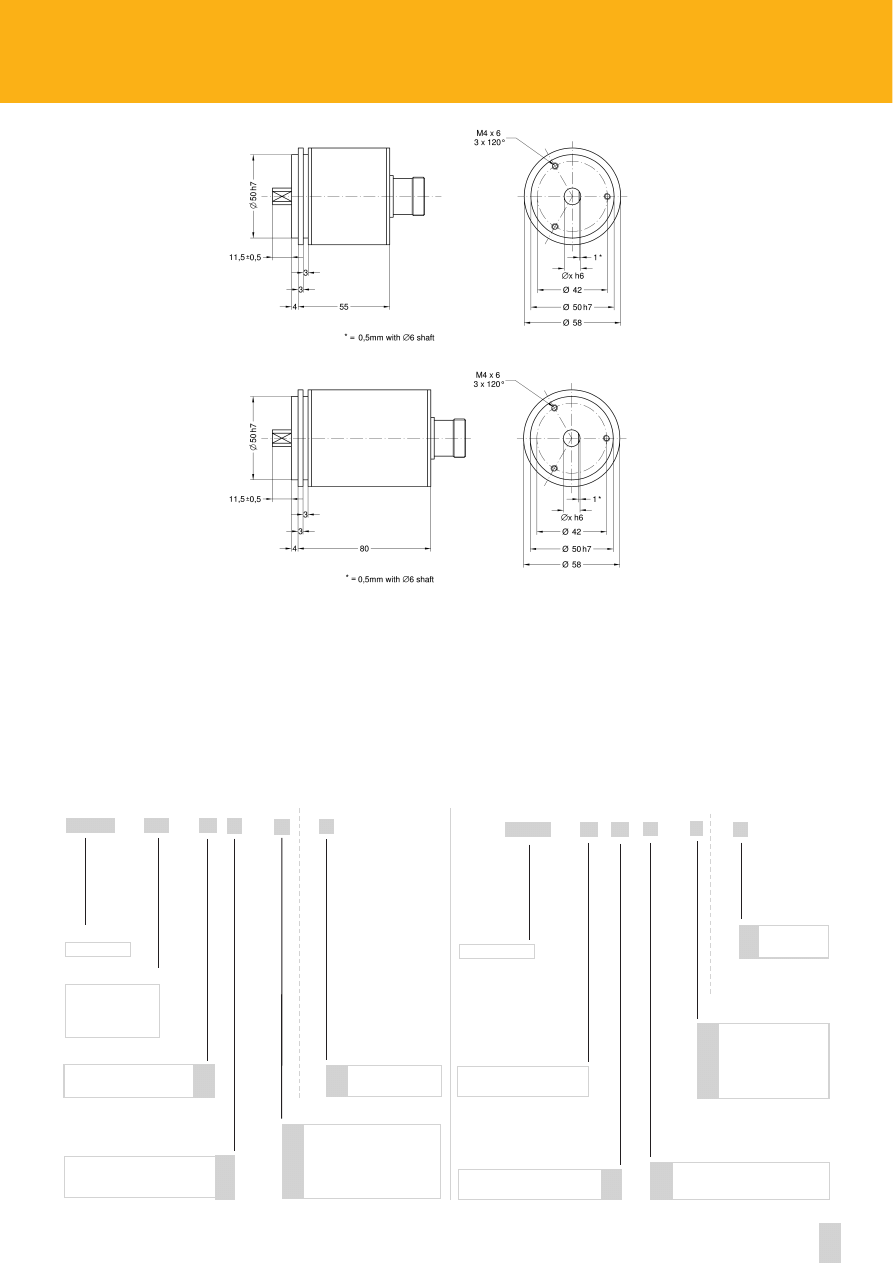
Side mount
connector
44
ISI - Incremental serial interface
The absolute encoder with ISI interface, supplies an incremental output with A and channel (90° shifted) and index pulse.
When switched on and enabled the encoder gives out a pulse train corresponding to the current absolute position.
This allows to measure absolute positions even if the following electronics has only an incremental encoder input.
Encoders with ISI interface are available as single turn and multi turn.
AS58
6 mm
8 mm
9.52 mm/ 3/8”
10 mm
12 mm
6
8
9.52
10
12
SERIES
SHAFT Ø
ORDERING CODE
X
X
X
XX
XXXX
/
-
-
-
Side mount connector
R
ADDITIONAL CODE
(indicate only if necessary)
X
80 = 720 PPR
12 = 1024 PPR
13 = 2048 PPR
PULSE RATE (PPR)
ISI incremental serial interface S
OUTPUT CODE
Push-Pull
Line Driver
Y
L
OUTPUT CIRCUITS
(1) Mechanical dimensions with connector output see on page 64
www.lika.biz
ORDERING CODE
ADDITIONAL CODE
(indicate only if necessary)
X
X
X
XXXX
-
- X
AM58
SERIES
PULSE RATE
ISI incremental serial interface S
OUTPUT CODE
Push-Pull
Line Driver
OUTPUT CIRCUITS
Y
L
R
X
6 mm
8 mm
9.52 mm/ 3/8”
10 mm
12 mm
6
8
9.52
10
12
SHAFT Ø
12/4096 = 1024 PPR x 4096 rev.
13/4096 = 2048 PPR x 4096 rev.
AS58 ISI
AM58 ISI
(1)
(1)
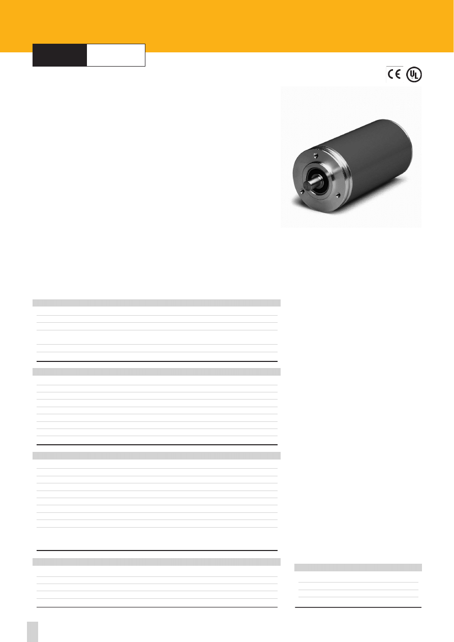
45
Specifications subject to changes without prior notice
ROTACOD
Absolute multi turn encoders
series
AM5
AM5
Shock:
100 g, 6 ms (acc. to MIL STD 202F)
Vibrations:
10 g, 5-2000 Hz (acc. to MIL STD 202F)
Operating temperature range:
-20°C +70°C (-4°F +158°F)
Storage temperature range:
-20°C +80°C (-4°F +176°F)
(98% R.H.without condensation)
Protection:
IP65
Option:
• Operating temperature range: -40°C +100°C (-40°F +212°F)
ENVIRONMENTAL SPECIFICATIONS
STD codes:
Gray, Binary
Power supply:
+10V +30V
Power consumption:
1,5 W
Output circuits:
NPN o.c., PNP o.c., Push-Pull
Output current:
40 mA max.
Output frequency:
60 kHz max.
Accuracy:
± 40% LSB
Protection:
Protected against inversion of polarity, Push-Pull protected against short-circuit
Optoelectronic life:
100.000 h min.
Options:
• LATCH output
• TRI-STATE output
• Electronic parity bit
ELECTRICAL SPECIFICATIONS
Housing:
non corroding
Flange:
non corroding
Bearings:
ABEC 5
Shaft:
stainless steel, non-magnetic
Light source:
GaAI diodes
MATERIALS
Dimensions:
see drawing
Shaft:
Ø 6, 8, 10, 12 mm
Shaft loading (axial and radial):
40 N max.
Shaft rotational speed:
6000 rpm max.
Moment of inertia:
80 gcm
2
Bearing life:
400x10
6
rev. min. (10
9
rev. min. with shaft loading of 20 N max.)
Weight:
~0,3 kg (10,6 oz)
Electrical connections:
cable 1 m (3.3 ft)
Options
(see on page 62)
:
• Inline connector E32MLP, EDB 25P
MECHANICAL SPECIFICATIONS
ACCESSORIES
E32MLS:
32 pin MIL mating connector
EDB 25S:
25 pin DSub mating connector
PAN/PGF:
flexible couplings
LKM-386:
fixing clamps
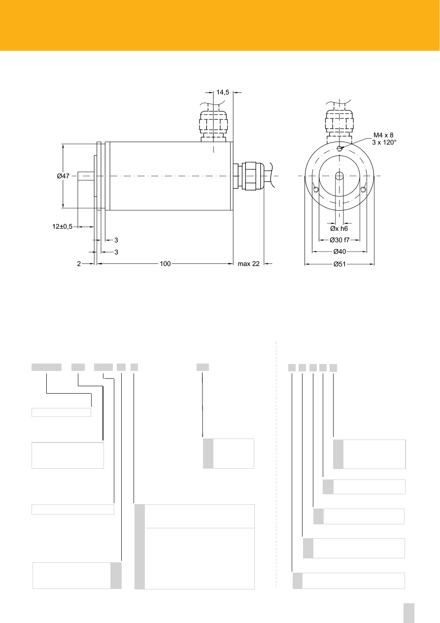
Side mount cable
46
www.lika.biz
AM5
AM5
16, 64, 256
6 mm
8 mm
10 mm
12 mm
6
8
10
12
SERIES
SHAFT DIAMETER
ORDERING CODE
X
XX
X
XX
XXX
XXX
-
-
/
Parity Bit
Operating temperature range
-40°C +100°C (-40°F +212°F)
R
B
K
ADDITIONAL CODE (indicate only if necessary)
Cable length on request
Lx
X X X X X
REVOLUTIONS
NPN o.c.
PNP o.c.
Push-Pull
on request
LATCH (NPN)
LATCH (PNP)
LATCH (Push-Pull)
TRI-STATE (NPN)
TRI-STATE (PNP)
LATCH+TRI-STATE (PNP)
LATCH+TRI-STATE (NPN)
N
P
Y
L
M
H
T
U
E
F
OUTPUT CIRCUITS
Binary
Gray
B
G
OUTPUT CODE
Inline connector E32MLP
Inline connector EDB 25P
V
W
Counts per revolution
1 - 2048
(see on page 66)
CODE
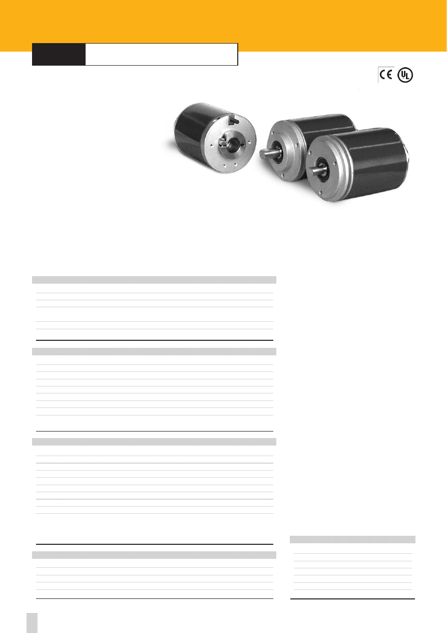
47
Specifications subject to changes without prior notice
ROTACOD
Absolute multi turn encoders
series
AM58
•
AM58S
•
AMC58
Shock:
100 g, 6 ms (acc. to MIL STD 202F)
Vibrations:
10 g, 5-2000 Hz (acc. to MIL STD 202F)
Operating temperature range:
-20°C +70°C (-4°F +158°F)
Storage temperature range:
-20°C +80°C (-4°F +176°F)
(98% R.H.without condensation)
Protection:
IP65
Option:
• Operating temperature range: -40°C +100°C (-40°F +212°F)
ENVIRONMENTAL SPECIFICATIONS
STD codes:
Gray, Binary
Power supply:
+10V +30V
Power consumption:
1,5 W
Output circuits:
NPN o.c., PNP o.c., Push-Pull, SSI
Output current:
40 mA max.
Output frequency:
60 kHz max.
Accuracy:
± 30% LSB
Protection:
Protected against inversion of polarity, Push-Pull protected against short-circuit
Optoelectronic life:
100.000 h min.
Options:
• LATCH output
• TRI-STATE output
• Electronic parity bit
• Electronic zero setting
ELECTRICAL SPECIFICATIONS
Housing:
non corroding
Flange:
non corroding
Bearings:
ABEC 5
Shaft:
stainless steel, non-magnetic
Light source:
GaAI diodes
MATERIALS
Dimensions:
see drawing
Shaft:
Ø 6, 8, 9.52, 10, 12, 14, 15 mm
Shaft loading (axial and radial):
100 N max.
Shaft rotational speed:
6000 rpm max.
Moment of inertia:
80 gcm
2
Bearing life:
400x10
6
rev. min. (10
9
rev. min. with shaft loading of 20 N max.)
Weight:
~0,3 kg (10,6 oz)
Electrical connections
(see on page 62)
:
E32MLP, E10MLP, E7MLP MIL connector
Options:
• EDB 25P DSub connector
(see on page 62)
• Cable output 1 m
MECHANICAL SPECIFICATIONS
E32MLS:
32 pin MIL mating connector
E7MLS:
7 pin MIL mating connector
E10MLS:
10 pin MIL mating connector
EDB 25S:
25 pin DSub mating connector
PAN/PGF:
flexible couplings
BR1:
reducing sleeves
LKM-386:
fixing clamps
ACCESSORIES
AM58-AM58S-AMC58
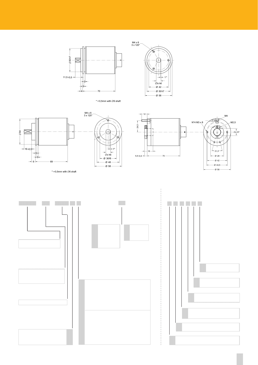
Side mount cable or connector
48
www.lika.biz
16, 256, 4096
REVOLUTIONS
AM58 - AM58S - AMC58
AMC59* - AMC60*
SERIES
ORDERING CODE
X
XX
X
XX
XXXX
XXX
-
/
Parity Bit
Operating temperature range
-40°C +100°C (-40°F +212°F)
R
B
K
ADDITIONAL CODE (indicate only if necessary)
Cable length on request
Lx
X X X X X X
Counts per revolution
1 - 131072
(see on page 66)
CODE
DSub 25 pin connector
W
Electronic zero setting
E
Binary
Gray
B
G
OUTPUT CODE
6 mm
8 mm
9.52 mm/ 3/8”
10 mm
12 mm
6
8
9.52
10
12
SHAFT DIAMETER
AM58 - AM58S
-
(1) Mechanical dimensions with connector output see on page 64
14 mm
15 mm
14
15
SHAFT DIAMETER
Reducing sleeves
see on page 75
AMCxx
NPN o.c.
PNP o.c.
Push-Pull
SSI serial output RS422 tree format (connector)
SSI serial output RS422 tree format (cable)
SSI serial output RS422 LSB alligned (connector)
SSI serial output RS422 LSB alligned (cable)
on request
LATCH (NPN)
LATCH (PNP)
LATCH (Push-Pull)
TRI-STATE (NPN)
TRI-STATE (PNP)
LATCH+TRI-STATE (PNP)
LATCH+TRI-STATE (NPN)
N
P
Y
S
R
A
B
L
M
H
T
U
E
F
OUTPUT CIRCUITS
* see notes on pag. 69
* Dimensional drawing on page 65
AM58
AM58S
AMC58
(1)
(1)
(1)
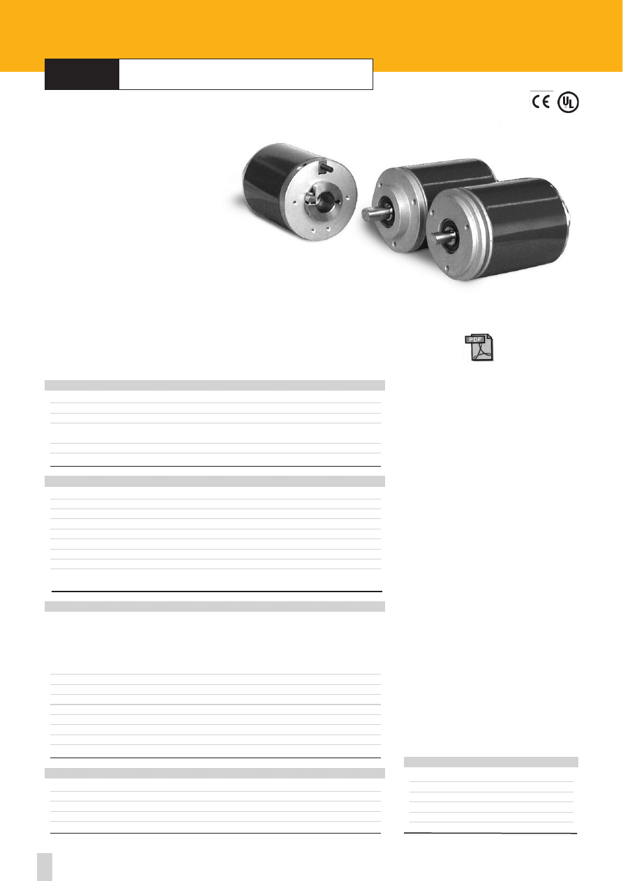
49
Specifications subject to changes without prior notice
ROTACOD
Absolute programmable Encoder
Shock:
100 g, 6 ms (acc. to MIL STD 202F)
Vibrations:
10 g, 5-2000 Hz (acc. to MIL STD 202F)
Operating temperature range:
-20°C +70°C (-4°F +158°F)
Storage temperature range:
-20°C +80°C (-4°F +176°F)
(98% R.H.without condensation)
Protection:
IP65
Option:
• Operating temperature range: -40°C +100°C (-40°F +212°F)
ENVIRONMENTAL SPECIFICATIONS
Programmable parameters:
• Output code: Gray, Binario, BCD
• Resolution: 8192 inf./rev. x 4096 rev. max
• Parity bit: even, odd
• Complementary, Zero setting, Offset
• Latch, Tri-state
• Teach-in of resolution
Power supply:
+10V +30V
Power consumption:
1,5 W
Output circuits:
NPN, PNP, Push-Pull, SSI
Output current:
40 mA max.
Output frequency:
50 kHz max.
Accuracy:
± 30% LSB
Protection:
Protected against inversion of polarity, Push-Pull protected against short-circuit
Optoelectronic life:
100.000 h min.
ELECTRICAL SPECIFICATIONS
Housing:
non corroding
Flange:
non corroding
Bearings:
ABEC 5
Shaft:
stainless steel, non-magnetic
Light source:
GaAI diodes
MATERIALS
Dimensions:
see drawing
Shaft:
Ø 6, 8, 9.52, 10, 12, 14, 15 mm
Shaft loading (axial and radial):
100 N max.
Shaft rotational speed:
6000 rpm max.
Moment of inertia:
80 gcm
2
Bearing life:
400x10
6
rev. min. (10
9
rev. min. with shaft loading of 20 N max.)
Weight:
~0,3 kg (10,6 oz)
Electrical connections
(see on page 62)
:
E41MLP MIL connector, EML 121 CONNEI connector
Options:
• E32MLP MIL connector
(see on page 62)
• Cable output 1 m
MECHANICAL SPECIFICATIONS
series
AM58 P
•
AM58S P
•
AMC58 P
www.lika.biz
- manual
- datasheet
- suppl. information
E41MLS:
41 pin MIL mating connector
E32MLS:
32 pin MIL mating connector
EPFL 121:
12 pin CONNEI mating connector
PAN/PGF:
flexible couplings
BR1:
reducing sleeves
LKM-386:
fixing clamps
ACCESSORIES
AM58 P-AM58S P-AMC58 P
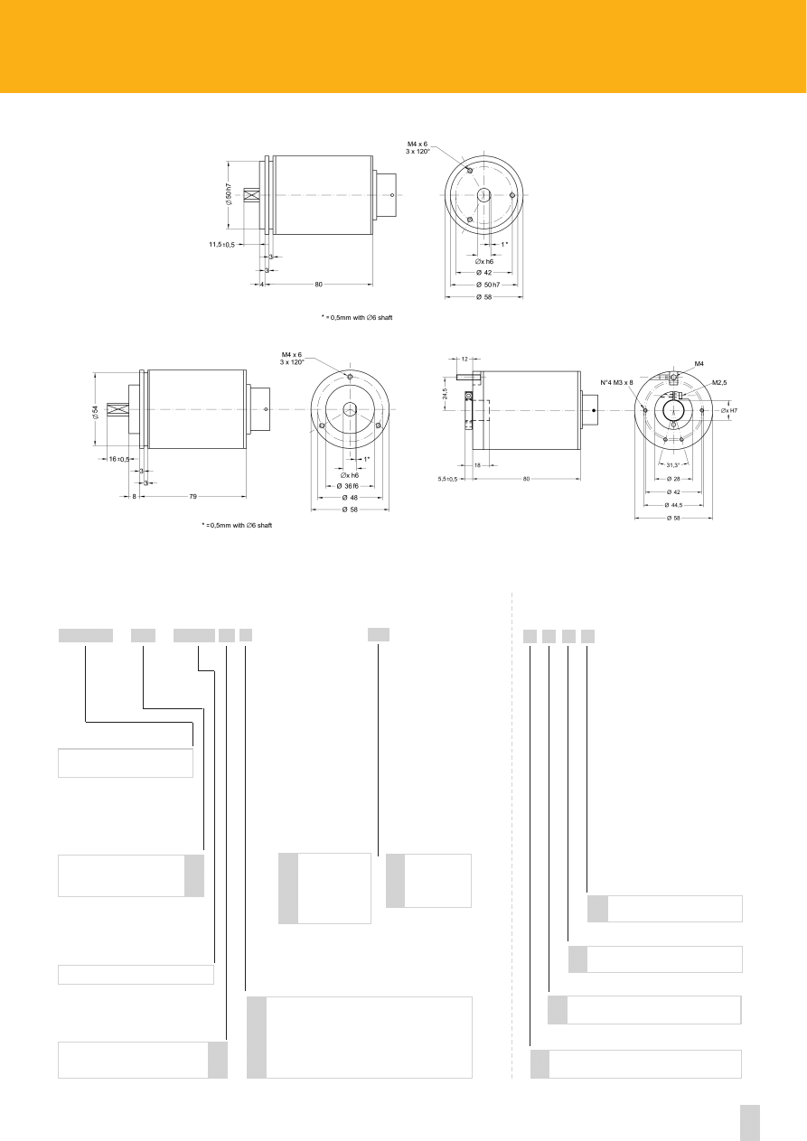
Side mount cable or connector
50
www.lika.biz
4096
REVOLUTIONS
AM58 - AM58S - AMC58
AMC59* - AMC60*
SERIES
ORDERING CODE
X
XX
X
XX
XXXX
XXX
-
/
Operating temperature range
-40°C +100°C (-40°F + 212°F)
R
K
ADDITIONAL CODE (indicate only if necessary)
32 pin MIL connector
V
Cable length on request
Lx
X X X X
NPN
PNP
Push-Pull
SSI serial output RS422 tree format (connector)
SSI serial output RS422 tree format (cable)
N
P
Y
S
R
OUTPUT CIRCUITS
* see notes on pag. 69
Programmable P
6 mm
8 mm
9.52 mm/ 3/8”
10 mm
12 mm
6
8
9.52
10
12
SHAFT DIAMETER
AM58 - AM58S
4096
8192
12
13
COUNTS PER REV.
(1) Mechanical dimensions with connector output see on page 64
-
14 mm
15 mm
14
15
SHAFT DIAMETER
Reducing sleeves
see on page 75
AMCxx
* Dimensional drawing on page 65
AM58
AM58S
AMC58
(1)
(1)
(1)
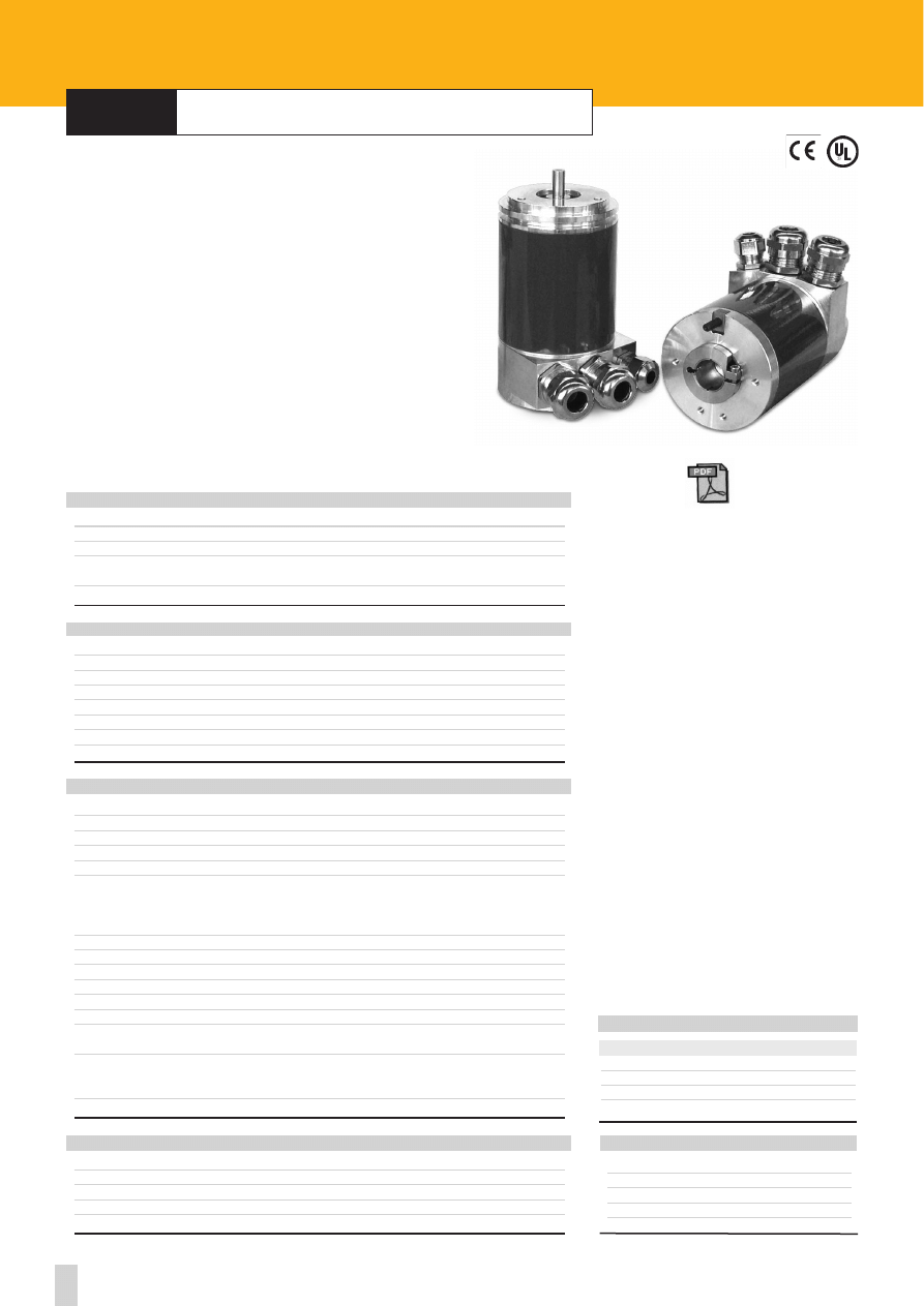
51
Specifications subject to changes without prior notice
ROTACOD
Absolute encoders with Profibus-DP output
series
A
X
58 PB
•
A
X
58S PB
•
A
X
C58 PB
A
X
58x PB
Shock:
100 g, 6 ms (acc. to MIL STD 202F)
Vibrations:
10 g, 5-2000Hz (acc. to MIL STD 202F)
Operating temperature range:
-20°C +70°C (-4°F +158°F)
Storage temperature range:
-20°C +80°C (-4°F +176°F)
(98% R.H.without condensation)
Protection:
IP65
ENVIRONMENTAL SPECIFICATIONS
STD codes:
binary
Power supply:
+10V +30V
Power consumption:
2,6W max.
Output frequency:
60 kHz max.
Accuracy:
30% LSB
Programmable parameters:
• counting direction
• resolution up to 8192 counts/rev. and 4096 rev.
• preset value
• offset value
Baudrate:
max 12 Mbit/sec.
Device address:
programmable by Dip-switches
Bus connection:
galvanically separated by opto-couplings
Interface:
Siemens Profibus controller SPC3
Class:
2 (PNO, order 3.062)
Output circuit:
Transceiver RS485
EMC:
electro-magnetic emission (EN 50081-2)
electro-magnetic compatibility (EN 50082-2)
Protection:
against inversion of polarity
against short circuit
against over voltage
Optoelectronic life:
100.000 h min.
ELECTRICAL SPECIFICATIONS
Housing:
non corroding
Flange:
non corroding
Bearings:
ABEC 5
Shaft:
stainless steel, non-magnetic
Light source:
GaAI diodes
MATERIALS
Dimensions:
see drawing
Shaft:
Ø 6, 8, 9.52, 10, 12, 14, 15 mm
Shaft loading (axial and radial):
40 N max.
Shaft rotational speed:
6000 rpm
Starting torque at 20°C:
< 1 Ncm (typical)
Moment of inertia:
~95 gcm
2
Bearing life:
400x10
6
rev. min. (10
9
rev. min. with shaft loading of 20 N max.)
Weight:
~0,5 kg (17,6 oz)
MECHANICAL SPECIFICATIONS
CLAMP
+
+10Vdc +30Vdc
-
0 Vdc
A
Receive/Transmit data negative
B
Receive/Transmit data positive
ELECTRICAL CONNECTIONS
www.lika.biz
- manual
- GSD file
- datasheet
CC-PB:
connection cap 3xPG
CC-PB-C:
connection cap with connectors
PAN/PGF:
flexible couplings
BR1:
reducing sleeves
LKM-386:
fixing clamps
ACCESSORIES
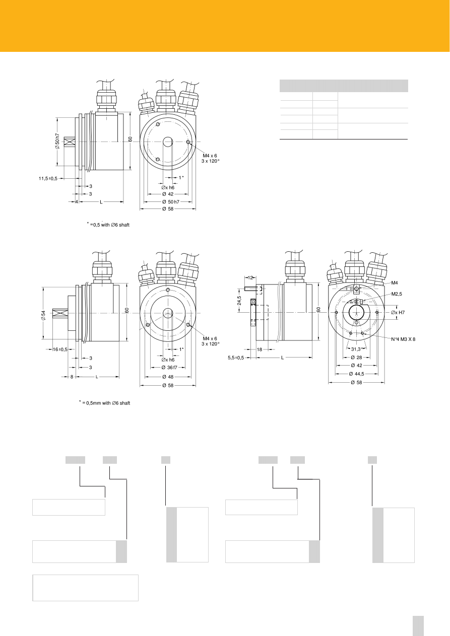
52
www.lika.biz
X
XXX
XX
/
ORDERING CODE MULTI TURN VERSION
4096
8192
12
13
INF. REV
PB -
ORDERING CODE SINGLE TURN VERSION
AS58 - AS58S - ASC58
ASC59* - ASC60*
SERIES
X
XXX
XX
/
4096
8192
12
13
INF. REV
4096 - PB -
AM58 - AM58S - AMC58
AMC59* - AMC60*
SERIES
* only AMCxx
AS58
83
AM58
98
AS58S
82
AM58S
97
ASC58
83
AMC58
98
6-10 h6 8-12 g6
6-8-10 h6 12 g6
14-15 H7
Series
L
D
Reducing sleeves
see on page 75
Accessories (to be ordered separately)
CC-PB Connection cap
CC-PB-C Connection cap with connectors
* Dimensional drawing on page 65
* Dimensional drawing on page 65
6 mm
8 mm
9.52mm/ 3/8”
10 mm
12 mm
14 mm*
15 mm*
6
8
9.52
10
12
14
15
SHAFT Ø
* only ASCxx
Reducing sleeves
see on page 75
6 mm
8 mm
9.52mm/ 3/8”
10 mm
12 mm
14 mm*
15 mm*
6
8
9.52
10
12
14
15
SHAFT Ø
AS58/AM58
AS58S/AM58S
ASC58/AMC58
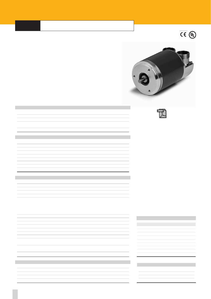
53
Specifications subject to changes without prior notice
ROTACOD
Absolute encoders with InterBus-S output
series
AX58 IB
•
AX58S IB
•
AXC58 IB
CC-IB mating connectors
1
D01
2
/D01
3
DI1
4
/DI1
5
GND
6
PE
7
+10Vdc +30Vdc
8
0 Vdc
9
/RBST
A
X
58x IB
Shock:
100 g, 6 ms (acc. to MIL STD 202F)
Vibrations:
10 g, 5-2000Hz (acc. to MIL STD 202F)
Operating temperature range:
-20°C +70°C (-4°F +158°F)
Storage temperature range:
-20°C +80°C (-4°F +176°F)
(98% R.H.without condensation)
Protection:
IP65
ENVIRONMENTAL SPECIFICATIONS
STD codes:
binary
Power supply:
+10V +30V
Power consumption:
3W max.
Output frequency:
60 kHz max.
Accuracy:
±1/2 LSB
Programmable parameters:
• counting direction
• Resolution up to 8192 counts/rev. and 4096 rev.
• Preset and offset value
• Zero setting
• Reset to default value
Baudrate:
500 Kbit/s
Device address:
programmable
Bus connection:
galvanically separated by opto-couplings
Interface:
InterBus-S IB8052 Supi 3
Class:
K3
Output:
RS485
Diagnostics:
see profile Encom-DIN 19258
EMC:
electro-magnetic emission (EN 50081-2)
electro-magnetic compatibility (EN 50082-2)
Protection:
against inversion of polarity
against short circuit
Optoelectronic life:
100.000 h min.
ELECTRICAL SPECIFICATIONS
Housing:
non corroding
Flange:
non corroding
Bearings:
ABEC 5
Shaft:
stainless steel, non-magnetic
Light source:
GaAI diodes
MATERIALS
Dimensions:
see drawing
Shaft:
Ø 6, 8, 9.52, 10, 12, 14, 15 mm
Shaft loading (axial and radial):
40 N max.
Shaft rotational speed:
6000 rpm
Starting torque at 20°C:
< 1 Ncm (typical)
Moment of inertia:
~95 gcm
2
Bearing life:
400x10
6
rev. min. (10
9
rev. min. with shaft loading of 20 N max.)
Weight:
~0,5 kg (17,6 oz)
Connection:
2 x 9 pin IP65 connector
MECHANICAL SPECIFICATIONS
ELECTRICAL CONNECTIONS
www.lika.biz
- manual
- datasheet
CC-IB:
mating connectors
PAN/PGF:
flexible couplings
BR1:
reducing sleeves
LKM-386:
fixing clamps
ACCESSORIES
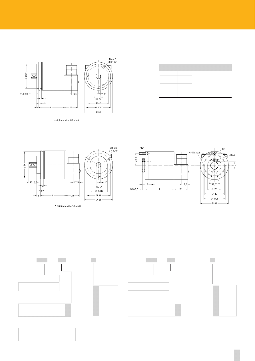
54
www.lika.biz
X
XXX
XX
/
ORDERING CODE MULTI TURN VERSION
4096
8192
12
13
COUNTS PER REV.
IB -
ORDERING CODE SINGLE TURN VERSION
AS58 - AS58S - ASC58
ASC59*- ASC60*
SERIES
X
XXX
XX
/
4096
8192
12
13
INF. REV
4096 - IB -
AM58 - AM58S - AMC58
AMC59* - AMC60*
SERIES
AS58
60
AM58
70
AS58S
69
AM58S
79
ASC58
60
AMC58
70
6-10 h6 8-12 g6
6-8-10 h6 12 g6
14-15 H7
Series
L
D
AS58/AM58
AS58S/AM58S
ASC58/AMC58
* only ASCxx
Reducing sleeves
see on page 75
* only AMCxx
Reducing sleeves
see on page 75
Accessories (to be ordered separately)
CC-IB InterBus-S mating connectors
* Dimensional drawing on page 65
* Dimensional drawing on page 65
6 mm
8 mm
9.52mm/ 3/8”
10 mm
12 mm
14 mm*
15 mm*
6
8
9.52
10
12
14
15
SHAFT Ø
6 mm
8 mm
9.52mm/ 3/8”
10 mm
12 mm
14 mm*
15 mm*
6
8
9.52
10
12
14
15
SHAFT Ø
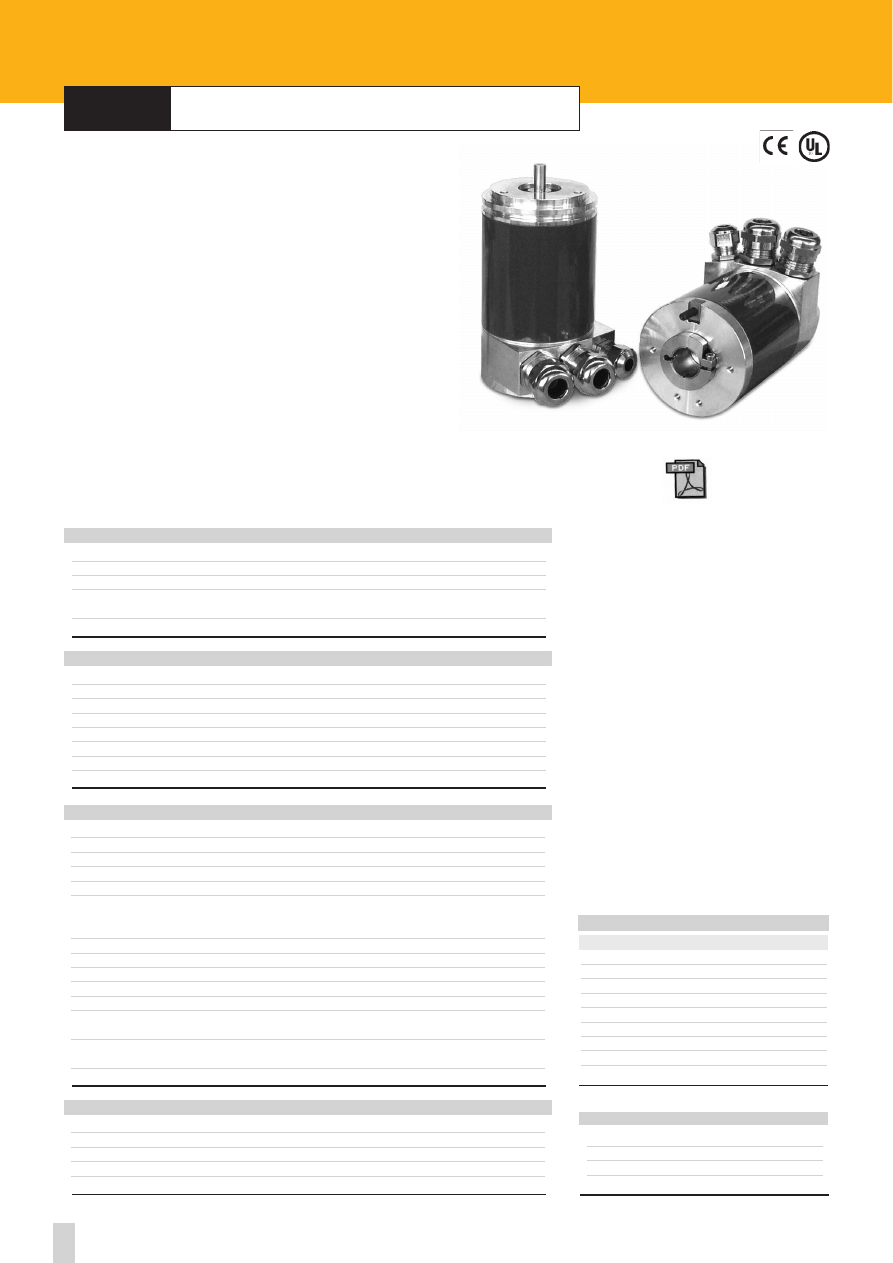
55
Specifications subject to changes without prior notice
ROTACOD
Absolute encoders with DEVICE NET output
series
A
X
58 FD
•
A
X
58S FD
•
A
X
C58 FD
CLAMP
I_
GND
+
+10Vdc +30Vdc
-
0 Vdc
CG
Reserved
CL
CAN Low
CH
CAN High
CG
Reserved
CL
CAN Low
CH
CAN High
Shock:
100 g, 6 ms (acc. to MIL STD 202F)
Vibrations:
10 g, 5-2000Hz (acc. to MIL STD 202F)
Operating temperature range:
-20°C +70°C (-4°F +158°F)
Storage temperature range:
-20°C +80°C (-4°F +176°F)
(98% R.H.without condensation)
Protection:
IP65
ENVIRONMENTAL SPECIFICATIONS
STD codes:
binary
Power supply:
+10V +30V
Power consumption:
3W max.
Output frequency:
60 kHz max.
Accuracy:
±1/2 LSB
Programmable parameters:
• counting direction
• Resolution up to 8192 counts/rev. and 4096 rev.
• Preset value
Baudrate:
programmable by Dip-switches
Device address:
programmable by Dip-switches
Bus connection:
galvanically separated by opto-couplings
Interface:
CAN transceiver (ISO/DIS 11898)
Class:
2 (CIA DSP 406)
EMC:
electro-magnetic emission (EN 50081-2)
electro-magnetic compatibility(EN 50082-2)
Protection:
against inversion of polarity
against short circuit
Optoelectronic life:
100.000 h min.
ELECTRICAL SPECIFICATIONS
Housing:
non corroding
Flange:
non corroding
Bearings:
ABEC 5
Shaft:
stainless steel, non-magnetic
Light source:
GaAI diodes
MATERIALS
Dimensions:
see drawing
Shaft:
Ø 6, 8, 9.52, 10, 12, 14, 15 mm
Shaft loading (axial and radial):
40 N max.
Shaft rotational speed:
6000 rpm max.
Starting torque at 20°C:
< 1 Ncm (typical)
Moment of inertia:
~95 gcm
2
Bearing life:
400x10
6
rev. min. (10
9
rev. min. with shaft loading of 20 N max.)
Weight:
~0,5 kg (17,6 oz)
MECHANICAL SPECIFICATIONS
ELECTRICAL CONNECTIONS
www.lika.biz
- manual
- EDS file
- datasheet
A
X
58x FD
CC-FD:
connection cap 2xPG
PAN/PGF:
flexible couplings
BR1:
reducing sleeves
LKM-386:
fixing clamps
ACCESSORIES
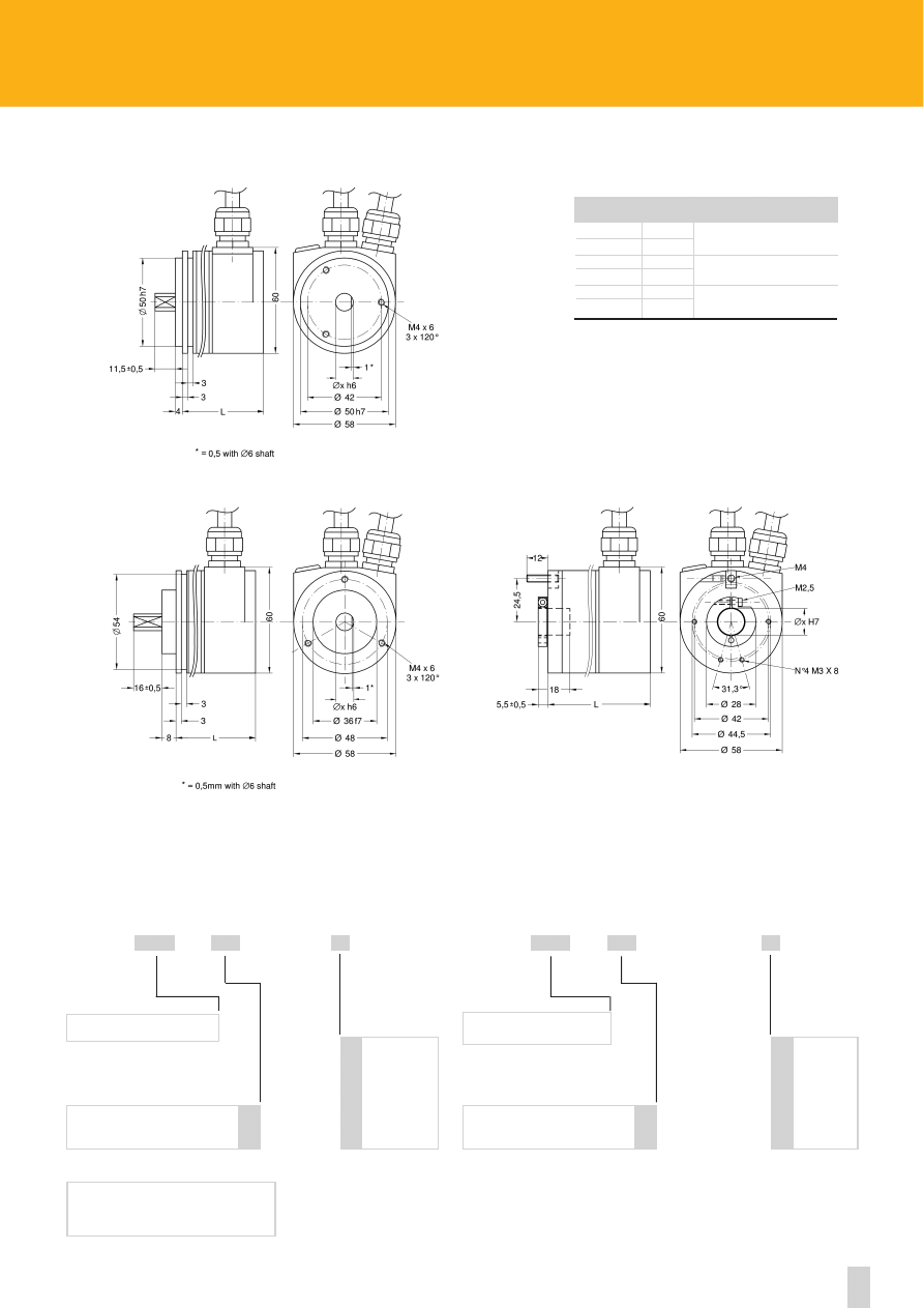
56
www.lika.biz
X
XXX
XX
/
ORDERING CODE MULTI TURN VERSION
4096
8192
12
13
COUNTS PER REV.
FD -
ORDERING CODE SINGLE TURN VERSION
AS58 - AS58S - ASC58
ASC59 *- ASC60 *
SERIES
X
XXX
XX
/
4096
8192
12
13
COUNTS PER REV.
4096 - FD -
-
AM58 - AM58S - AMC58
AMC59* - AMC60*
SERIES
AS58
83
AM58
98
AS58S
82
AM58S
97
ASC58
83
AMC58
98
6-10 h6 8-12 g6
6-8-10 h6 12 g6
14-15 H7
Series
L
D
6 mm
8 mm
9.52 mm/ 3/8”
10 mm
12 mm
14 mm*
15 mm*
6
8
9.52
10
12
14
15
SHAFT Ø
Reducing sleeves
see on page 75
6 mm
8 mm
9.52 mm/ 3/8”
10 mm
12 mm
14 mm*
15 mm*
6
8
9.52
10
12
14
15
SHAFT Ø
* only AMCxx
Reducing sleeves
see page 75
Accessories (to be ordered separately)
CC-FD
Connection cap
* Dimensional drawing on page 65
* Dimensional drawing on page 65
* only ASCxx
AS58/AM58
AS58S/AM58S
ASC58/AMC58
57
Specifications subject to changes without prior notice
ROTACOD
Absolutes encoders with CANopen output
series
A
X
58 CB
•
A
X
58S CB
•
A
X
C58 CB
CLAMP
I_
GND
+
+10Vdc +30Vdc
-
0 Vdc
CG
CAN GND
CL
CAN Low
CH
CAN High
CG
CAN GND
CL
CAN Low
CH
CAN High
Shock:
100 g, 6 ms (acc. to MIL STD 202F)
Vibrations:
10 g, 5-2000Hz (acc. to MIL STD 202F)
Operating temperature range:
-20°C +70°C (-4°F +158°F)
Storage temperature range:
-20°C +80°C (-4°F +176°F)
(98% R.H.without condensation)
Protection:
IP65
ENVIRONMENTAL SPECIFICATIONS
STD codes:
binary
Power supply:
+10V +30V
Power consumption:
3W max.
Output frequency:
60 kHz max.
Accuracy:
±1/2 LSB
Programmable parameters:
• counting direction
• Resolution up to 8192 counts/rev. and 4096 rev.
• Preset value
• Two software limit switches
• Transmission mode: Polled, Cyclic, Sync
Baudrate:
programmable by Dip-switches
Device address:
programmable by Dip-switches
Bus connection:
galvanically separated by opto-couplings
Interface:
CAN transceiver (ISO/DIS 11898)
Class:
2 (CIA DSP 406)
EMC:
electro-magnetic emission (EN 50081-2)
electro-magnetic compatibility (EN 50082-2)
Protection:
against inversion of polarity
against short circuit
Optoelectronic life:
100.000 h min.
ELECTRICAL SPECIFICATIONS
Housing:
non corroding
Flange:
non corroding
Bearings:
ABEC 5
Shaft:
stainless steel, non-magnetic
Light source:
GaAI diodes
MATERIALS
Dimensions:
see drawing
Shaft:
Ø 6, 8, 9.52, 10, 12, 14, 15 mm
Shaft loading (axial and radial):
40 N max.
Shaft rotational speed: 6000 rpm max.
Starting torque at 20°C:
< 1 Ncm (typical)
Moment of inertia:
~95 gcm
2
Bearing life:
400x10
6
rev. min. (10
9
rev. min. with shaft loading of 20 N max.)
Weight:
~0,5 kg (17,6 oz)
MECHANICAL SPECIFICATIONS
ELECTRICAL CONNECTIONS
www.lika.biz
- manual
- EDS file
- datasheet
AX58x CB
CC-CB:
connection cap 3xPG
PAN/PGF:
flexible couplings
BR1:
reducing sleeves
LKM-386:
fixing clamps
ACCESSORIES
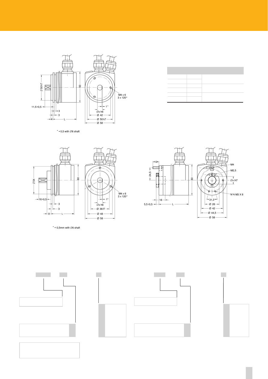
58
www.lika.biz
X
XXXX
XX
/
ORDERING CODE MULTI TURN VERSION
4096
8192
12
13
COUNTS PER REV.
CB -
ORDERING CODE SINGLE TURN VERSION
AS58 - AS58S - ASC58
ASC59 *- ASC60 *
SERIES
X
XXX
XX
/
4096
8192
12
13
COUNTS PER REV.
4096 - CB -
SERIES
AS58
83
AM58
98
AS58S
82
AM58S
97
ASC58
83
AMC58
98
6-10 h6 8-12 g6
6-8-10 h6 12 g6
14-15 H7
Series
L
D
6 mm
8 mm
9.52 mm/ 3/8”
10 mm
12 mm
14 mm*
15 mm*
6
8
9.52
10
12
14
15
SHAFT Ø
* only ASCxx
Reducing sleeves
see page 75
* only AMCxx
Reducing sleeves
see page 75
Accessories (to be ordered separately)
CC-CB Connection cap
* Dimensional drawing on page 65
* Dimensional drawing on page 65
6 mm
8 mm
9.52 mm/ 3/8”
10 mm
12 mm
14 mm*
15 mm*
6
8
9.52
10
12
14
15
SHAFT Ø
AM58 - AM58S - AMC58
AMC59 * - AMC60 *
AS58/AM58
AS58S/AM58S
ASC58/AMC58

1
function
1
A
2
/A
3
B
4
/B
5
0
6
/0
7
n.c.
8
+Vdc
9
0 Vdc GND
1 = EDE 9S 9 pin DSub inline connector
59
Specifications subject to changes without prior notice
Electrical connections incremental encoders
For long distances and/or environments with electric noise, LIKA 3x2x0,25 mm
2
+ 2x1x0,5 mm
2
cable is suggested.
CONNECTIONS WITH NORMAL OUTPUTS
1
2
function
A
1
A
B
2
n.c.
C
3
B
D
4
n.c.
E
5
0
F
6
0 Vdc GND
G
7
+Vdc
1 = E7 MLS 7 pin MIL mating connector
2 = T 3475001 7 pin TUCHEL mating connector
CONNECTIONS WITH COMPLEMENTARY OUTPUTS
1
2
3
function
A
C
1
A
B
D
2
/A
C
E
3
B
D
F
4
/B
E
G
5
0
F
H
6
/0
G M
11
n.c.
H
B
12
n.c.
I
J
8
0 Vdc GND
J
A
7
+Vdc
K
9 n.c.
L
10 n.c.
1 = E10MLS 10 pin MIL mating connector
2 = T 3635000 12 pin TUCHEL mating connector
3 = EPFL 121 12 pin CONNEI mating connector
CONNECTIONS WITH CABLE OUTPUT
1
2
function
brown
yellow
A
-
blue
/A
blue
green
B
-
orange
/B
white
white
0
-
grey
/0
red
red
+Vdc
black
black
0 Vdc GND
1 = cable LIKA 5x0,25 mm
2
(LIYCY)
2 = cable LIKA 8x0,25 mm
2
(LIYCY)
Screening:
Copper
External Ø:
5 leads 5 mm
8 leads 6,2 mm
Conductors resistance:
79
Ω/Km
Bending radius:
fixed Ø x 5 mm
in motion Ø x 15 mm
CABLE SPECIFICATIONS
ROTAPULS
ELECTRICAL CONNECTIONS WITH 9 PIN DSUB INLINE CONNECTOR
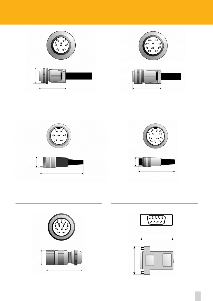
9 pin DSub mating connector
Ordering code:
EDE9S
60
www.lika.biz
7 pin MIL mating connector
Ordering code:
E7MLS
7 pin TUCHEL mating connector
Ordering code:
T3475001
12 pin CONNEI mating connector
Ordering code:
EPFL 121
12 pin TUCHEL mating connector
Ordering code:
T3635000
Ø32
55,5
Ø18
68
Ø26
~~
64
31
46
Ø18
68
Ø34
64,5
10 pin MIL mating connector
Ordering code:
E10MLS
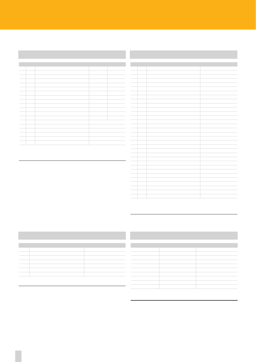
61
Specifications subject to changes without prior notice
ROTACOD
Electrical connections absolute encoders
ABSOLUTE SINGLE TURN ENCODER CONNECTIONS
1
2
3
G/B
BCD
A
1
brown
1LSB
1
B
2
red
2
2
C
3
pink
3
4
D
4
yellow
4
8
E
5
green
5
10
F
6
blue
6
20
G
7
violet
7
40
H
8
grey
8
80
J
9
white
9
100
K
10
black
10
200
L
11
white/green
11
400
M
12
brown/green
12
800
N
13
1000
P
zero setting*
R
latch*
S
red/blue
tri-state*
U
13
grey/pink
complementary
V
14
white/yellow
+10Vdc +30Vdc
T
15
yellow/brown
0Vdc
*on request
1 = E19MLS 19 pin MIL connector
2 = EDA 15S 15 pin DSUB connector
3 = cable LIYCY 16 x 0.14 mm
2
SSI SERIAL CONNECTIONS
SSI SERIAL CONNECTIONS
1
2
funzione/function
A
white
clock in +
B
brown
clock in -
C
green
data +
D
yellow
data -
E
F
blue
complementary
G
H
pink
zero setting
I
black
0 Vdc GND
J
red
+10 Vdc +30 Vdc
1 = E10MLS 10 pin MIL mating connector
2 = cable LIKA 3x2x0,25 mm
2
+ 2x1x0,5 mm
2
ABSOLUTE MULTI TURN ENCODER CONNECTIONS
1
2
3
G/B
A
1
brown
1LSB
B
2
red
2
C
3
pink
3
D
4
yellow
4
E
5
green
5
F
6
blue
6
G
7
violet
7
H
8
grey
8
J
9
white
9
K
10
black
10
L
11
brown/red
11
M
12
white/red
12
N
13
blue/red
13
P
14
pink/grey
14
R
15
white/yellow
15
S
16
brown/green
16
T
17
white/green
17
U
18
yellow/brown
18
V
19
white/blue
19
W
20
brown/blue
20
X
white/pink
21
Y
white/grey
22
Z
pink/brown
23
a
grey/brown
24
b
brown/black
25
c
white/black
parity bit *
d
grey/green
zero setting *
e
21
yellow/grey
latch *
f
22
pink/green
tri-state *
g
23
yellow/pink
complementary
h
24
green/blue
+10Vdc +30Vdc
i
25
yellow/blue
0Vdc GND
*on request
1 = E32MLS 32 pin MIL connector
2 = EDB 25S 25 pin DSUB connector
3 = cable LIYCY 32 x 0.14 mm
2
For long distances and/or environments with electric noise, LIKA 3x2x0,25 mm
2
+ 2x1x0,5 mm
2
cable is suggested.
1
2
funzione/function
A
white
clock in +
B
brown
clock in -
C
green
data out +
D
yellow
data out -
E
blue
complementary
F
black
0 Vdc GND
G
red
+10Vdc +30Vdc
1 = E7MLS 7 pin MIL mating connector
2 = cable LIKA 3x2x0,25 mm
2
+ 2x1x0,5 mm
2
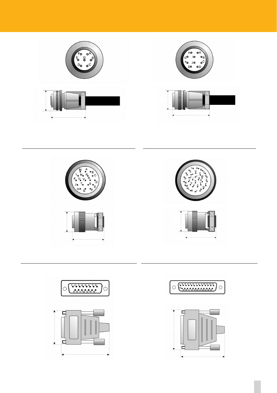
62
www.lika.biz
19 pin MIL mating connector
Ordering code:
E19MLS
32 pin MIL mating connector
Ordering code:
E32MLS
15 pin DSub mating connector
Ordering code:
EDA15S
25 pin DSub mating connector
Ordering code:
EDB25S
7 pin MIL mating connector
Ordering code:
E7MLS
10 pin MIL mating connector
Ordering code:
E10MLS
Ø32
55,5
Ø29
47
40
58
54
59
Ø35
51
Ø34
64,5
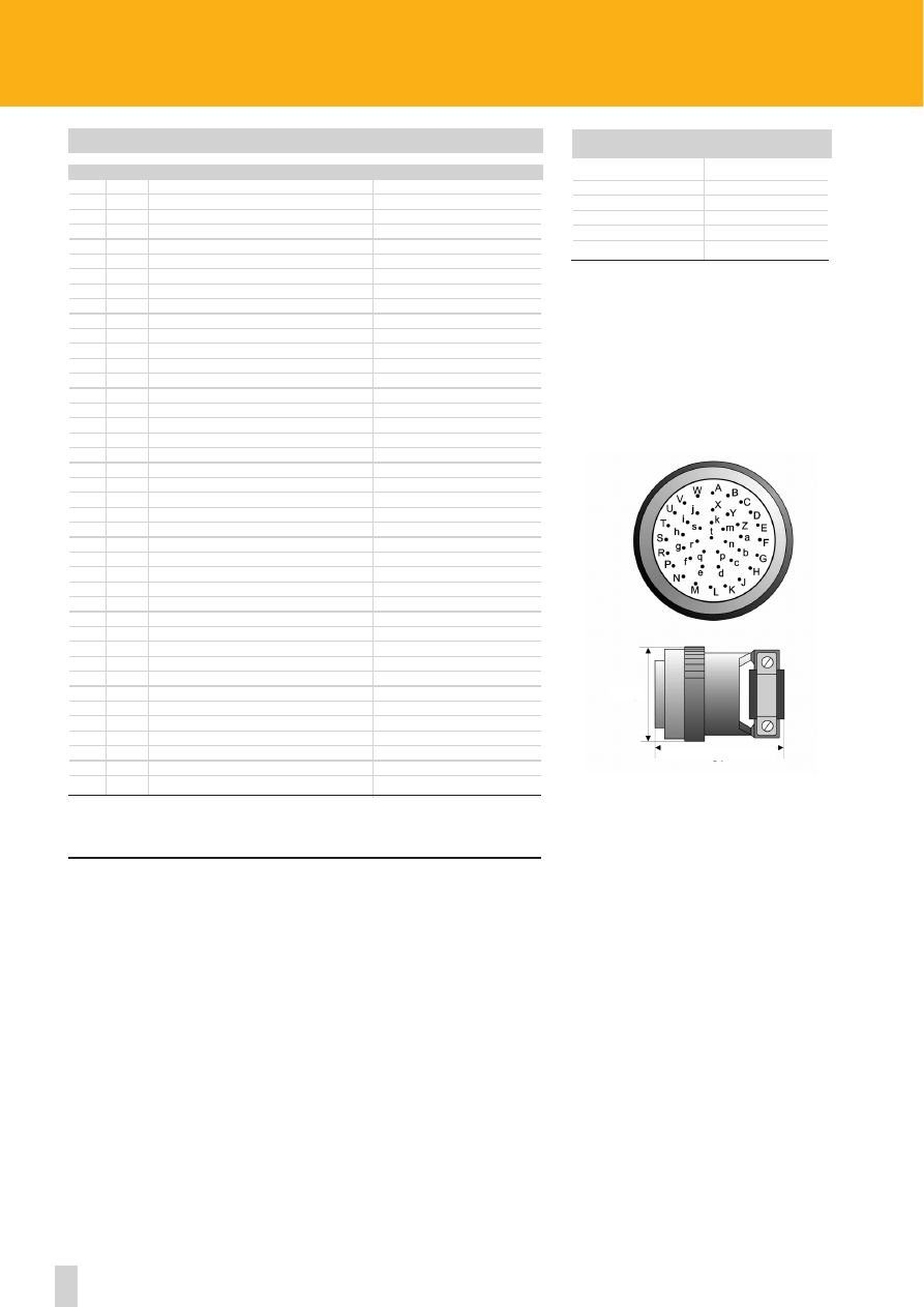
63
Specifications subject to changes without prior notice
www.lika.biz
ROTACOD
Electrical connections AM58 P series
AM58 P CONNECTIONS
1
2
3
OUT
A
A
brown
1 LSB
B
B
red
2
C
C
pink
3
D
D
yellow
4
E
E
green
5
F
F
blue
6
G
G
violet
7
H
H
grey
8
J
J
white
9
K
K
black
10
L
L
brown/red
11
M
M
white/red
12
N
N
blue/red
13
P
P
pink/grey
14
R
R
white/yellow
15
S
S
brown/green
16
T
T
white/green
17
U
U
yellow/brown
18
V
V
white/blue
19
W
W
brown/blue
20
X
X
white/pink
21
Y
Y
white/grey
22
Z
Z
pink/brown
23
a
a
grey/brown
24
b
b
brown/black
25MSB
c
c
white/black
Parity bit
d
d
grey/green
zero setting
e
e
yellow/grey
Latch
f
f
pink/green
TxD
g
g
yellow/pink
RxD
h
green/blue
Gnd RxD/TxD
i
yellow/blue
Tri-State
j
green/red
External reset
k
yellow/red
Preset 1
m
green/black
Preset 2
n
yellow/black
p
pink/blue
q
r
grey/red
complementary
s
h
pink/red
10Vdc 30Vdc
t
j
grey/blue
0 Vdc GND
1 = E41MLS 41 pin MIL connector
2 = E32MLS 32 pin MIL connector
3 = Cable 40 x 0,14 mm
2
EPFL 121 12 pin CONNEI mating connector
1
Clock - 7
Zero Setting
2
Clock + 8
External Reset
3
Data + 9
Preset 1
4
Data - 10
Preset 2
5
TxD 11
10Vdc 30Vdc
6
RxD 12
0 Vdc GND
SSI SERIAL CONNECTIONS
For long distances and/or environments with electric noise, LIKA 3x2x0,25 mm
2
+ 2x1x0,5 mm
2
cable is suggested.
41 pin MIL mating connector
Ordering code:
E41MLS
Ø38,5
51
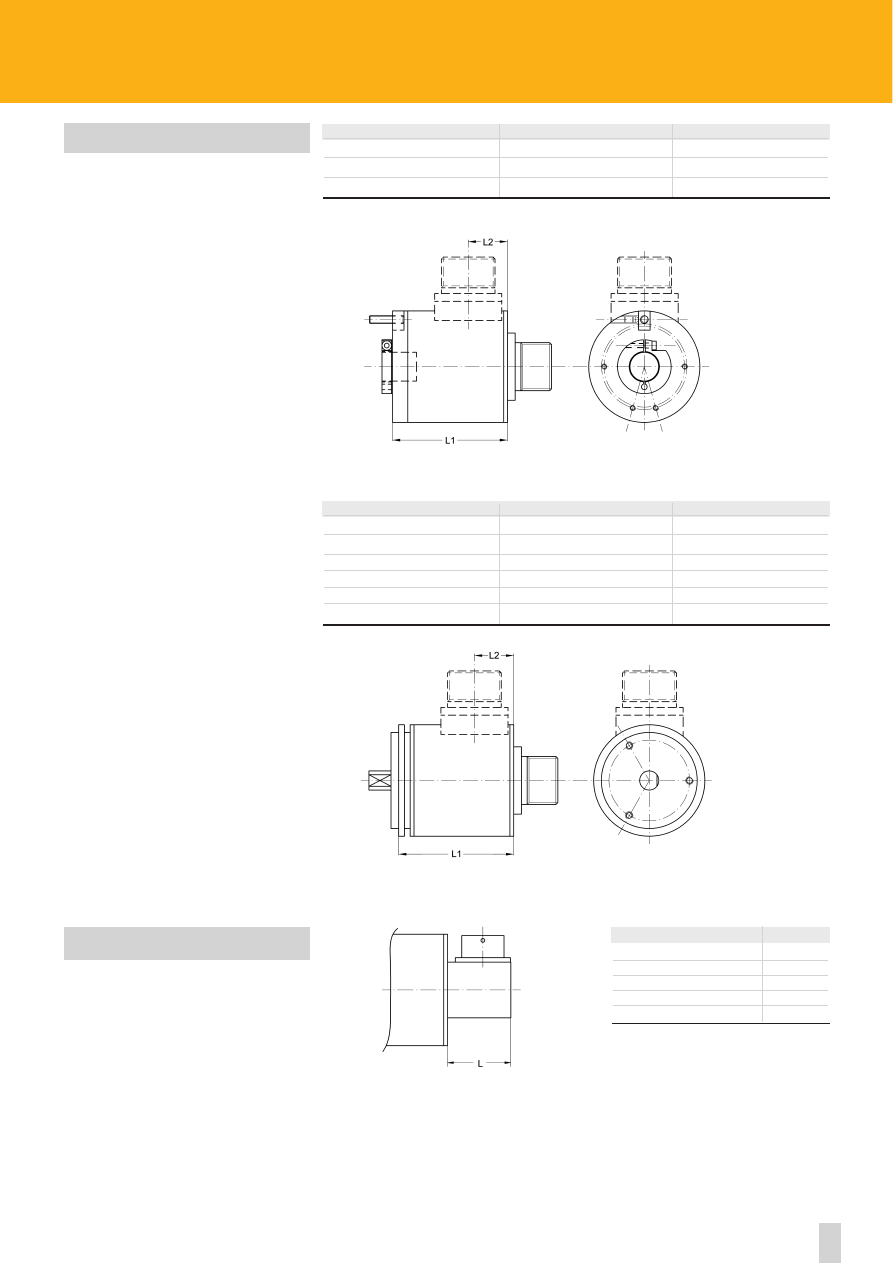
64
CONNECTOR
AXIAL
RADIAL
L1
L1
L2
7 pin MIL
55 mm
60 mm
21,5 mm
10 pin MIL
55 mm
60 mm
21,5 mm
ROTAPULS
•
ROTACOD
Mechanical dimensions with radial connector
MECHANICAL DIMENSIONS WITH
OUTPUT CONNECTOR
RADIAL OUTPUT R
CONNECTOR
AXIAL
RADIAL
L1
L1
L2
7 pin MIL
55 mm
60 mm
21,5 mm
10 pin MIL
55 mm
60 mm
21,5 mm
12 pin CONNEI
55 mm
50 mm
16,5 mm
7 pin TUCHEL
55 mm
55 mm
16 mm
12 pin TUCHEL
55 mm
55 mm
16 mm
CONNECTOR
L
7 pin MIL
36 mm
10 pin MIL
38 mm
12 pin MIL
25 mm
19 pin MIL
33 mm
32 pin MIL
38 mm
www.lika.biz
CK58
I58 - I58S
Ax58x
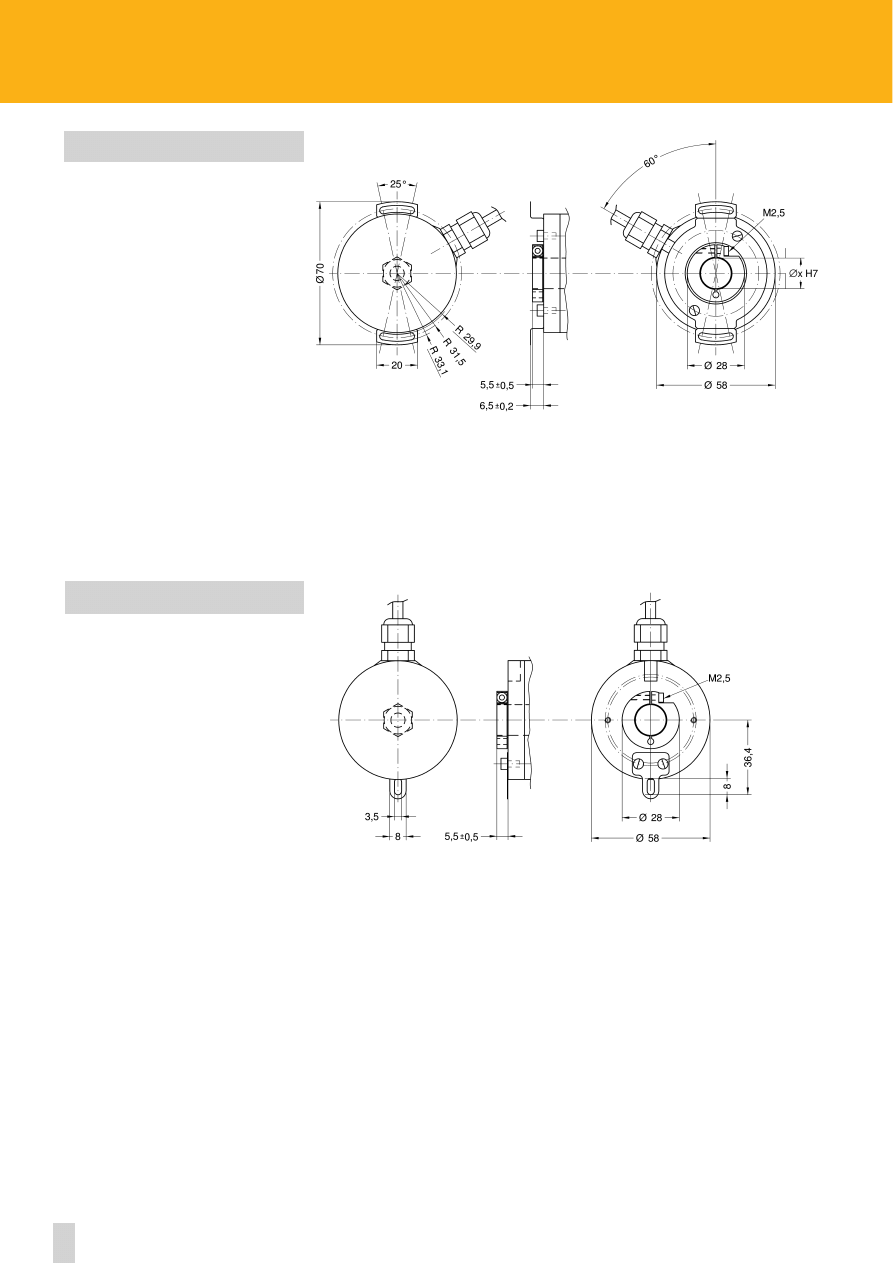
65
Specifications subject to changes without prior notice
www.lika.biz
ROTAPULS
•
ROTACOD
Fixing variation for hollow shaft encoders
ENCODER’S DIMENSIONS SERIES xx59
Fixing variation for hollow shaft encoders series: C59, CK59, ASC59 and AMC59.
See the data-sheet for any other information required.
xx59
ENCODER’S DIMENSIONS SERIES xx60
Fixing variation for hollow shaft encoders series: C60, CK60, ASC60 and AMC60.
See the data-sheet for any other information required.
xx60

66
ORD. CODE
COUNTS REV.
REVOLUTIONS
TOT. COUNTS
ASxx 04
16
1
16
ASxx 05
32
1
32
ASxx 06
64
1
64
ASxx 07
128
1
128
ASxx 18
180
1
180
ASxx 08
256
1
256
ASxx 36
360
1
360
ASxx 09
512
1
512
ASxx 72
720
1
720
ASxx 90
900
1
900
ASxx 10
1024
1
1024
ASxx 40
1440
1
1440
ASxx 50
1800
1
1800
ASxx 11
2048
1
2048
ASxx 80
2880
1
2880
ASxx 81
3600
1
3600
ASxx 12
4096
1
4096
ASxx 13
8192
1
8192
ASxx 14
16384
1
16384
ASxx 15
32768
1
32768
ASxx 16
65536
1
65536
ASxx 17
131072
1
131072
SCHEDULE COUNTS/REV. ABSOLUTE SINGLE TURN ENCODERS
• Shifted Gray code (see on page 70)
ORD. CODE
COUNTS REV.
REVOLUTIONS
TOT. COUNTS
AMxx 04/16
16
16
256
AMxx 05/16
32
16
512
AMxx 06/16
64
16
1024
AMxx 07/16
128
16
2048
AMxx 08/16
256
16
4096
AMxx 09/16
512
16
8192
AMxx 10/16
1024
16
16384
AMxx 11/16
2048
16
32768
AMxx 12/16
4096
16
65536
AMxx 13/16
8192
16
131072
AMxx 04/64
16
64
1024
AMxx 05/64
32
64
2048
AMxx 06/64
64
64
4096
AMxx 07/64
128
64
8192
AMxx 08/64
256
64
16384
AMxx 09/64
512
64
32768
AMxx 10/64
1024
64
65536
AMxx 11/64
2048
64
131072
AMxx 12/64
4096
64
262144
AMxx 13/64
8192
64
524288
AMxx 04/256
16
256
4096
AMxx 05/256
32
256
8192
AMxx 06/256
64
256
16384
AMxx 07/256
128
256
32768
AMxx 08/256
256
256
65536
AMxx 09/256
512
256
131072
AMxx 10/256
1024
256
262144
AMxx 11/256
2048
256
524288
AMxx 12/256
4096
256
1048576
AMxx 13/256
8192
256
2097152
AMxx 04/4096
16
4096
65536
AMxx 05/4096
32
4096
131072
AMxx 06/4096
64
4096
262144
AMxx 07/4096
128
4096
524288
AMxx 08/4096
256
4096
1048576
AMxx 09/4096
512
4096
2097152
AMxx 10/4096
1024
4096
4194304
AMxx 11/4096
2048
4096
8388608
AMxx 12/4096
4096
4096
16777216
AMxx 13/4096
8192
4096
33554432
AMxx 14/4096
16384
4096
67108864
AMxx 15/4096
32768
4096
13421772
AMxx 16/4096
65536
4096
26843544
AMxx 17/4096
131072
4096
53687088
SCHEDULE COUNTS/REV. ABSOLUTE MULTI TURN ENCODERS
•
•
•
•
•
•
•
•
www.lika.biz
ROTACOD
Absolute encoders resolution schedules
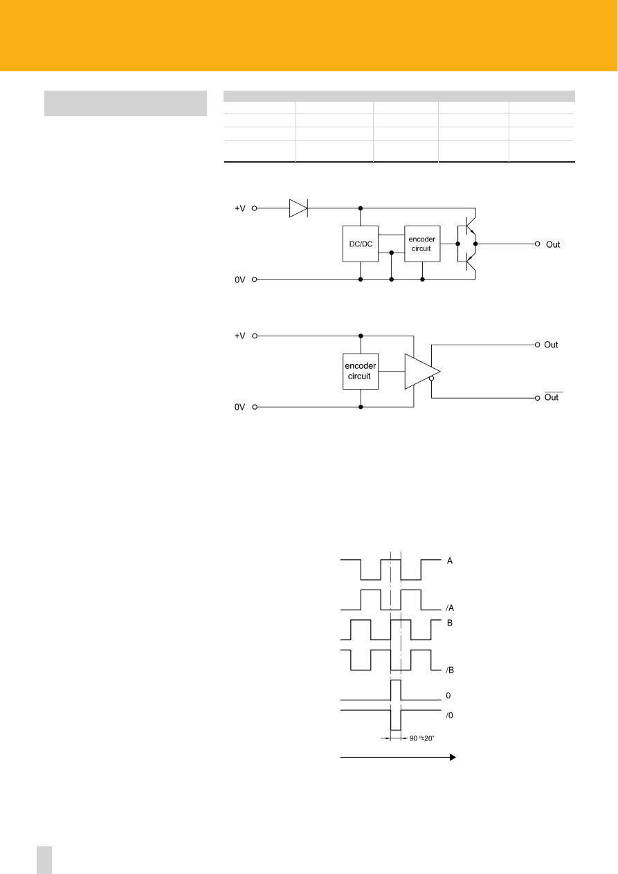
67
ROTAPULS
Technical information
NOTES ON THE OUTPUT CIRCUITS
- For the transmission of signals for distances > 10 m is it advisable to use Push-Pull or universal circuit
outputs or Line Driver. The Push-Pull output is suitable for interface connection even with circuits which
have NPN or PNP inputs.
- For the connection between the encoder and the control unit, it is advised to use a screened cable with
screening connected to ground.
CW counting direction, seen from shaft side
OUTPUT SIGNALS
Output
Push-Pull
Line Driver
Universal circuit
Unit
I
OUT
max
40
40
100
mA
Z
OUT
(impendance)
60+30%
30
Ω
V
OUT
low@40mA
≤ 0,5
≤ 0,5
≤ 0,4
Vdc
V
OUT
high@40mA
(Vin - 1,25)
≥ 2,5
(Vin - 1,25)
Vdc
PUSH-PULL
LINE DRIVER TTL/UNIVERSAL CIRCUIT
www.lika.biz
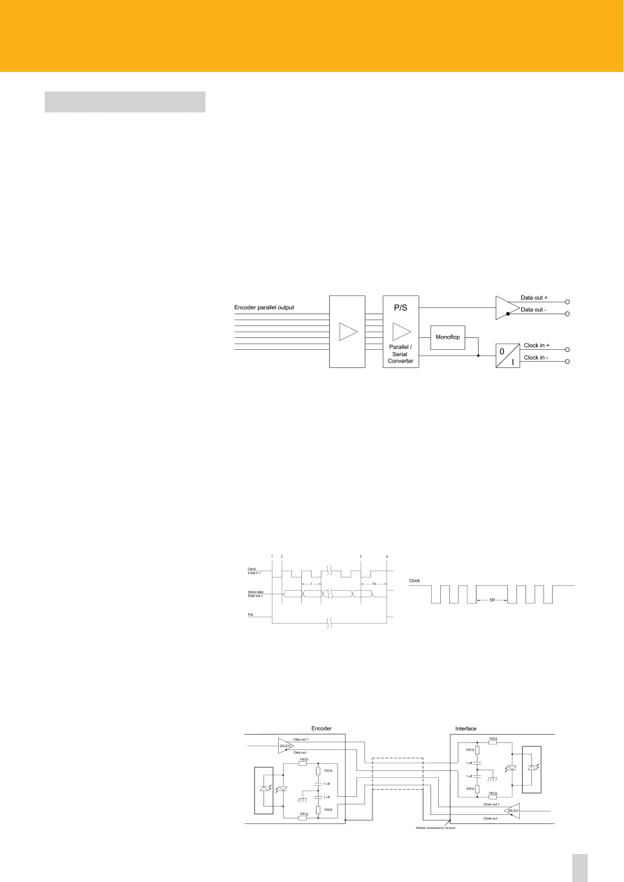
68
ROTACOD
Technical information
DESCRIPTION
The standard of transmission SSI “serial sincronous interface” is worldwide diffused and available for a large
range of commercial transducers and control devices. Compared to parallel or asincronous transmission it has
the following advantages:
- less conductors;
- less electronic components;
- encoder is galvanically separated by means of optocouplers;
- transmission rate up to 1,5 Mbps;
- hardware interface indipendent from absolute encoder resolution (nr. of transmitted data).
The interface works with only one 6 wire cable. Balanced transmission provides a high noise immunity. The
possibility of working in multiplexing with a high number of encoders allows reliable process checks a
simplicity of the system and of data managment.
BLOCK DIAGRAM
OPERATION SYSTEM
When the Clock is changed for the first time from high to low (1) instruction is given to the monoflop, the
period (Tm) of which has to be longer than the period of the Clock T. The output of the monoflop controls the
serial/parallel converter PS. When the Clock changes from low to high (2), the most significant bit MSB is sent
to the serial output. With every other change of the Clock the data is transmitted to the serial output of the
encoder until the least significant bit LSB. The interfaces works with encoders up to 25 bits.
TIMING
With the last change of the Clock (3) form low to high, the data transmission cycle is terminated. After the
time Tm the encoder is ready for the next transmission.
ADVISED INTERFACE
SSI OUTPUT
www.lika.biz
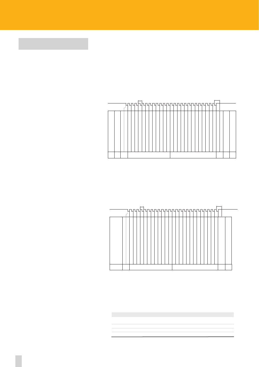
69
ROTACOD
Technical information
The difference between the data transmission of a single turn encoder and a multi turn
encoder is only given by the number of bits and Clocks. The single turn version allows max. 13
bits (8192 Counts/rev.), while the multi turn version allows max. 25 bits (8192 Counts/rev. x
4096 rev.).
“TREE FORMAT” PROTOCOL (STANDARD)
The most common protocol divides the transmitted data into 12 “nr. of rev. bits”, on the left
side of the central axes and 13 “steps per rev. bits” on the right side of the axes (see diagram).
If less than 13 +12 bits are required, the transmitted data is filled up with “zeroes” in order to
obtain always the length of 25 bits.
“LSB RIGHT ALLIGNED” PROTOCOL
A variation of the “tree format” consists of the right allignment of the bits, beginning form MSB to
LSB. The “nr. of rev. bits” are placed before the “counts per rev. bits” (see diagram). If less than 13 +12
bits are required, the transmitted data is filled up with leading “zeroes” in order to obtain the length
of 25 bits.
RECOMMENDED TRANSMISSION RATES
The SSI interface has a frequency of data transmission from 100 kHz to 1 MHz with a clock sig-
nal which has a typical logic level of 5 V. The output signal is given, in the standard version,
with level 5 V. The transmission rate (baudrate) depends on the length of cables.
12
11
10
9
8
7
6
5
4
3
2
1
1
1
1
1
1
1
1
1
1
1
1
1
1
1
1
1
1
1
1
1
1
1
1
1
25
0
0
0
0
0
0
0
0
0
0
0
24
24
0
0
0
0
0
0
0
0
0
0
23
23
23
0
0
0
0
0
0
0
0
0
22
22
22
22
0
0
0
0
0
0
0
0
21
21
21
21
21
0
0
0
0
0
0
0
20
20
20
20
20
20
0
0
0
0
0
0
19
19
19
19
19
19
19
0
0
0
0
0
18
18
18
18
18
18
18
18
0
0
0
0
17
17
17
17
17
17
17
17
17
0
0
0
16
16
16
16
16
16
16
16
16
16
0
0
15
15
15
15
15
15
15
15
15
15
15
0
14
14
14
14
14
14
14
14
14
14
14
14
13
13
13
13
13
13
13
13
13
13
13
13
12
12
12
12
12
12
12
12
12
12
12
12
11
11
11
11
11
11
11
11
11
11
11
0
10
10
10
10
10
10
10
10
10
10
0
0
9
9
9
9
9
9
9
9
9
0
0
0
8
8
8
8
8
8
8
8
0
0
0
0
7
7
7
7
7
7
7
0
0
0
0
0
6
6
6
6
6
6
0
0
0
0
0
0
5
5
5
5
5
0
0
0
0
0
0
0
4
4
4
4
0
0
0
0
0
0
0
0
3
3
3
0
0
0
0
0
0
0
0
0
2
2
0
0
0
0
0
0
0
0
0
0
1
0
0
0
0
0
0
0
0
0
0
0
0
0
0
0
0
0
0
0
0
0
0
0
1
1
1
1
1
1
1
1
1
1
1
1
8192
4096
2048
1024
512
256
128
64
32
16
8
4
13
12
11
10
9
8
7
6
5
4
3
2
4096
2048
1024
512
256
128
64
32
16
8
4
2
T
TM
LSB
MSB
1
2
3
4
5
6
7
8
9
10 11 12 13
14 15 16 17 18 19 20 21 22 23 24 25
CLOCK
LOOP in +
bit
bit multigiro / multiturn bits
bit monogiro / singleturn bits
inf.giro
Cpr
bit
n.giri
rev.
Bit 25
Bit 24
Bit 23
Bit 22
Bit 21
Bit 20
Bit 19
Bit 18
Bit 17
Bit 16
Bit 15
Bit 14
Bit 13
Bit 12
1
1
1
1
1
1
1
1
1
1
1
1
1
1
1
1
1
1
1
1
1
1
1
1
1
1
1
1
25
0
0
0
0
0
0
0
0
0
0
0
0
0
24
24
0
0
0
0
0
0
0
0
0
0
0
0
23
23
23
0
0
0
0
0
0
0
0
0
0
0
22
22
22
22
0
0
0
0
0
0
0
0
0
0
21
21
21
21
21
0
0
0
0
0
0
0
0
0
20
20
20
20
20
20
0
0
0
0
0
0
0
0
19
19
19
19
19
19
19
0
0
0
0
0
0
0
18
18
18
18
18
18
18
18
0
0
0
0
0
0
17
17
17
17
17
17
17
17
17
0
0
0
0
0
16
16
16
16
16
16
16
16
16
16
0
0
0
0
15
15
15
15
15
15
15
15
15
15
15
0
0
0
14
14
14
14
14
14
14
14
14
14
14
14
0
0
13
13
13
13
13
13
13
13
13
13
13
13
13
0
12
12
12
12
12
12
12
12
12
12
12
12
12
12
11
11
11
11
11
11
11
11
11
11
11
11
11
11
10
10
10
10
10
10
10
10
10
10
10
10
10
10
9
9
9
9
9
9
9
9
9
9
9
9
9
9
8
8
8
8
8
8
8
8
8
8
8
8
8
8
7
7
7
7
7
7
7
7
7
7
7
7
7
7
6
6
6
6
6
6
6
6
6
6
6
6
6
6
5
5
5
5
5
5
5
5
5
5
5
5
5
5
4
4
4
4
4
4
4
4
4
4
4
4
4
4
3
3
3
3
3
3
3
3
3
3
3
3
3
3
2
2
2
2
2
2
2
2
2
2
2
2
2
2
1
1
1
1
1
1
1
1
1
1
1
1
1
1
0
0
0
0
0
0
0
0
0
0
0
0
0
0
1
1
1
1
1
1
1
1
1
1
1
1
1
1
T
TM
LSB
MSB
1
2
3
4
5
6
7
8
9
10 11 12 13
14 15 16 17 18 19 20 21 22 23 24 25
CLOCK
LOOP in +
bit
bit multigiro / multiturn bits
bit monogiro /singleturn bits
inf.giro
Cpr
bit
n.giri
rev.
Cable length
Baudrate
< 50 m
< 400 kHz
< 100 m
< 300 kHz
< 200 m
< 200 kHz
< 400 m
< 100 kHz
TRANSMISSION PROTOCOLS
www.lika.biz
70
ROTACOD
Technical information
SHIFTED CODES
It is sometimes necessary to have a quantity of output information which is different from the values expressed by
powers of 2 (2
n
). These cases are commonly referred to as “shifted” Gray and Binary codes. It is useful to note that in
these cases:
- the initial count value is not zero.
- the final count value does not coincide with the max. value of the information requested.
To calculate the initial and final values of the output information, it is necessary to use the following algorithm:
Example
a shifted Gray code of 360 counts/rev. is required
∆ = integral Gray - shifted Gray
2
where:
Integral Gray: represents the standard value of the information (expressed by 2°) immediately superior to the
max. value desired.
shifted Gray: represents the max. value of the information in shifted code desired.
∆:
represents the initial count value (first output information).
∆-1:
represents the quantity to be added to the max. value of information required to obtain the
final count value (last output information).
therefore:
∆ = 512 - 360 = 76;
2
∆-1 = 75; 360 + 75 = 435
First position
Last position
76
435
Shifted code encoders can only be supplied in single-turn version.
www.lika.biz
360°
Tot. counts = 360
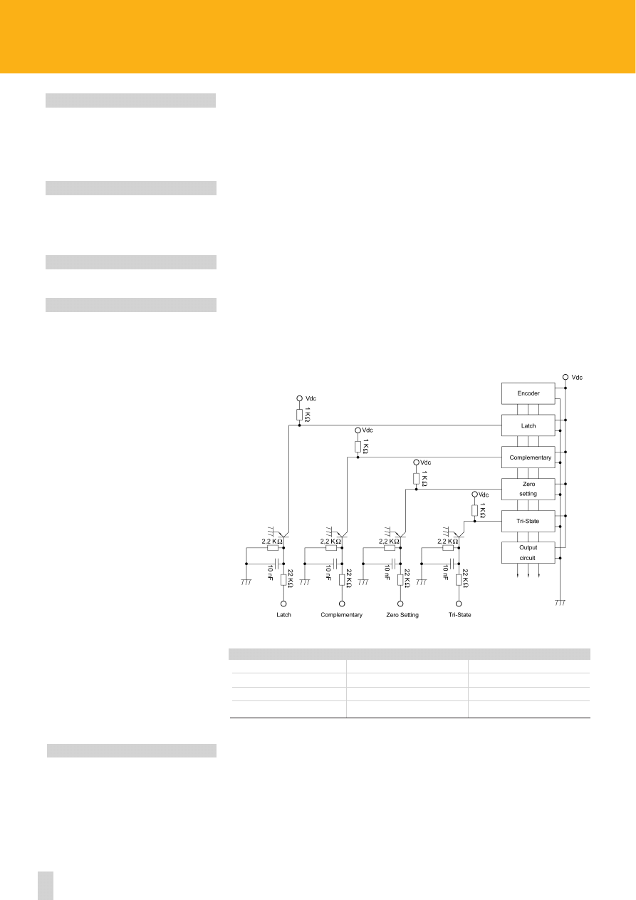
71
ROTACOD
Technical information
LATCH
TRI-STATE
COMPLEMENTARY
ZERO SETTING
The LATCH circuit allows the storage of the information value which the encoder shows in output at a
particular moment.
The above-mentioned information value will remain present in output until the LATCH signal is deactivated.
In this way it is possible, if for instance the data transmission speed of the encoder is fast in comparison to
the data aquisition time of the interface electronics, to freeze the information for the amount of time neces-
sary for the data to be acquired.
The TRI-STATE circuit allows the transmission of output information from the encoder to be blocked.
In this way, it is possible for instance to work with several encoders in parallel (multiplexing) using a single
control unit, acquiring the information values relative to the angular position of each encoder with an
updating time equal to the duration of the multiplexing cycle.
The COMPLEMENTARY circuit allows the count up also if the shaft turn ccw. This feature is standard on all
models.
The output value is set to zero (reset) with a signal from PLC or other device. The internal microprocessor use
this signal to perform reset of information value.
The encoder reset is possible for a frequency count ranging from zero to 2,5 kHz.
The reset signal has to bee logic level HIGH (from 10V. to 30V.) for 100 µsec. minimum.
Electronic Parity Bit is active when the sum of output bits, logic level 1, is even.
Function
1 (high) ≥ 10 Vdc
0 (low) ≤ 8 Vdc
TRI-STATE
Active outputs
Encoder disabled
LATCH
Data in memory
Latch deactivated
COMPLENTARY
CCW count
CW count
ZERO SETTING
Zero active
Zero deactivate
www.lika.biz
ELECTRONIC PARITY BIT
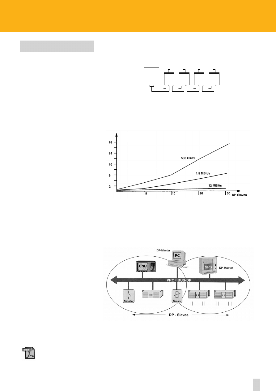
Profibus-DP is a communication system which consist of a Master or system manager, slave units and a
two wire cable for data transmission.
The Master can connect up to 125 Slaves, divided into groups of 32, through a special two wire cable
designed for high speed transmission up to 12 Mbits.
Slave units can be installed and recognized by the Master by means of the configuration file .GSE (or
.GSD, .GSI depending upon the used language). This file contains all the information which are necessary
for the identification and the communication with the Master. The information are e.g. vendor ID of the
unit, supported transmission rates, dimensions of the exchanged data fields, set-up parameters,
available diagnostic messages.
The PROFIBUS-DP network has a tree structure and the main branches are represented by the units
and/or sub-networks managed by other Masters.
In order to indentify a unit of the network, users can assign a “DA” address to each unit which is
communicated to the Master during it’s initialization.
72
ROTACOD
Technical information
PROFIBUS-DP
www.lika.biz
- manual
- GSD file
- datasheet
- more info & links
24Vdc 24Vdc 24Vdc 24Vdc
PLC
+
DP- Master
ENCODER
ENCODER
ENCODER
ENCODER
BUS SYSTEM
www.lika.biz
Cicle time [ms]
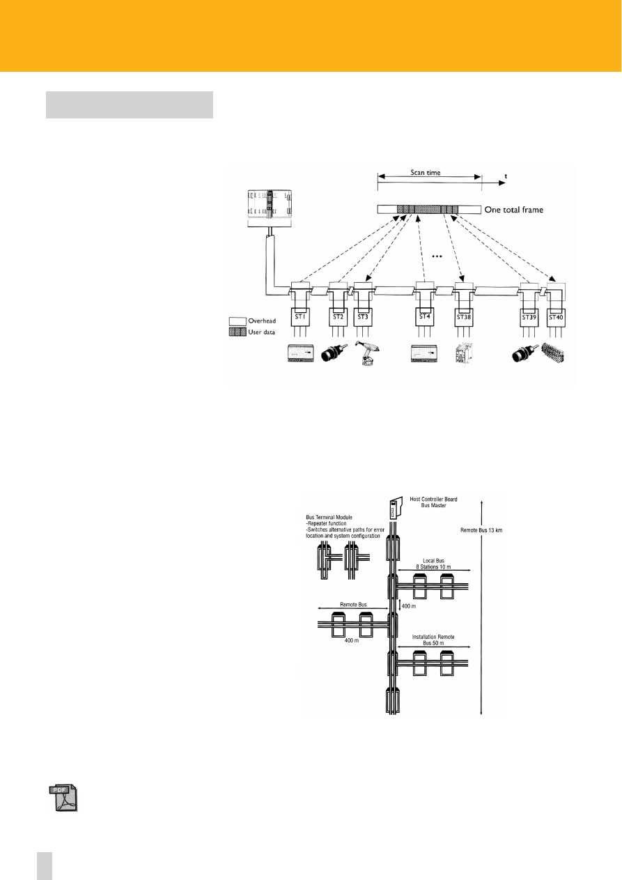
73
ROTACOD
Technical information
INTERBUS-S
This fieldbus has been worked out as a non proprietary sensor and actuator fieldbus. InterBus-S is a
Master-Slave system where communication between the devices is done by means of a single-message
containing information for/from all devices (added messages telegram).
In this way a very high efficiency is obtained because the part of the message which doesn’t contain
information but only data for transmission control is reduced to the minimum.
A network can connect up to 512 devices on a max. length of 400 mt. or up to 13 km by using a signal
repeater. The typical transmission rate (baudrate) is 500 Kbit/s.
InterBus-S devices are distinguished in 4 different profiles, from 1 to 4. The differences are the length
of transmitted data (1 and 2) and the possibility both to receive and to transmit data (3 and 4).
Profibus for example distinguishes only between programmable and not programmable devices (class 2
and 1).
www.lika.biz
- manual
- datasheet
- more info & links
www.lika.biz
74
ROTACOD
Technical information
CAN AND DEVICENET
The CAN protocol was originally developed by Bosch and Intel for the automotive industry and is now
largely diffused in the industrial automation market as well.
CAN is a multi-master system that allows messages to be delivered to multiple devices simultaneously.
An identifier field in the data provides the means for multiple priority levels (used in arbitration), more
efficient transfer of I/O data and multiple consumers.
CAN is used as the basis of the DeviceNet standard and defines the base level communications protocol
and the hardware. The table shows the relative levels of CAN and DeviceNet protocols. CAN is a basic
data link protocol while DeviceNet is an application-level protocol.
DeviceNet is a network with up to 64 nodes (CAN max. 32) and a baudrate depending on the networks
length of max. 500 kbit/s (CAN max. 1 Mbit/s). The system can be set up as peer-to-peer, master/slave or
both. Data is accessible to every component of the system simultaneously in order to provide a very effi-
cient use of the network bandwidth.
As shown in the diagram, the data contained in each frame can be up to 8 byte long. In case two or more
nodes try to access the network simultaneously, CAN uses a unique non-destructive bit-wise arbitration
mechanism. This CAN-specific feature allows resolution of collisions without loss of bandwidth or
resending of data by the higher priority node.
Interframe
Space
Interframe Space
End of Frame
Ack Delimiter
Ack Slot
CRC Delimiter
CRC Sequence
Data Field
Control Field
RTR Bit
Identifier
Start of Frame
1
bit
1
bit
1
bit
1
bit
11
bits
15
bits
1
bit
6
bits
7
bits
>=3
bits
0 .. 8
bytes
Arbitration Field
www.lika.biz
- manual
- EDS file
- datasheet
- more info & links
DeviceNet Protocol
ISO Application (Layer 7)
CAN Protocol
ISO Data Link (Layer 2)
Physical Layer
ISO Physical (Layer 1)
Transmission Media
ISO Media (Layer 0)
www.lika.biz
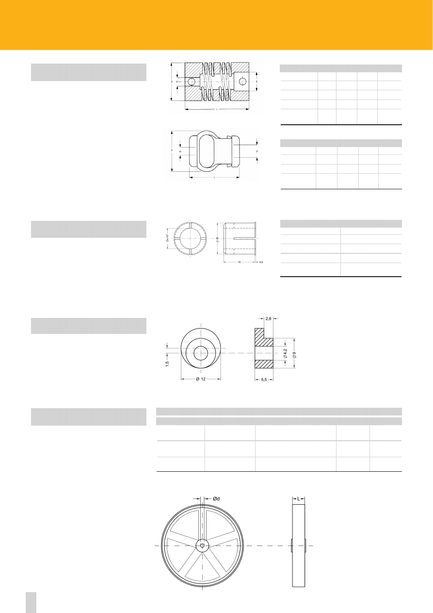
75
www.lika.biz
ROTAPULS
•
ROTACOD
Accessories
FLEXIBLE COUPLINGS
FIXING CLAMPS
METRIC WHEELS
PAN COUPLINGS
Mod.
L
D
d
d1
PAN 6
22
19
6
6
PAN 8
24
25
8
8
PAN 10
24
25
10
10
PAN 12
24
25
12
12
PGF COUPLINGS
Mod.
L
D
d
d1
PGF 6
29
22
6
6
PGF 8
29
22
8
8
PGF 10
29
22
10
10
METRIC WHEELS
Mod.
Circ.
Superficie/Surface
Ø d
L
RM200GZ
200 mm
rubber (knurled)
6 mm
12 mm
RM500G
500 mm
rubber (smooth)
8 mm
24 mm
RM500Z
500 mm
metal (knurled)
8 mm
24 mm
REDUCING SLEEVES
BR1-12
Ø 12mm h7
BR1-10
Ø 10mm h7
BR1-9.52
Ø 9.52mm h7
BR1-8
Ø 8mm h7
BR1-6
Ø 6mm h7
BR1 REDUCING SLEEVES
Complete range of couplings avaiable on www.lika.biz
See mounting instructions on page 78
KIT LKM-386 is sup-
plied as a set of 3
clamps, screws and
nuts.
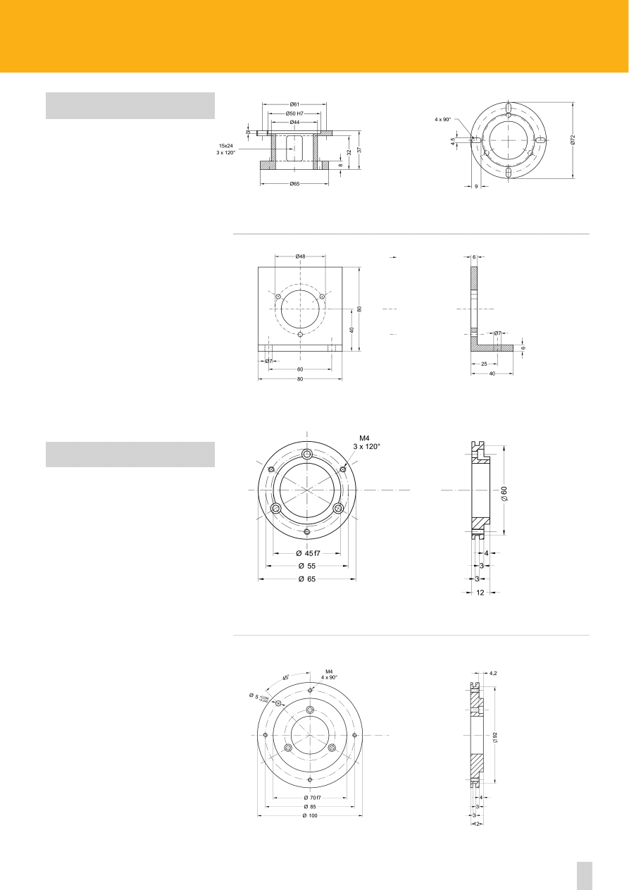
76
ROTAPULS
•
ROTACOD
Accessories
MOUNTING BELLS - BRACKETS
Combine with I58S, I65 and Ax58S
Combine with I58S, I65 and Ax58S
ADAPTING FLANGES
Adapts the Ax58S series to the old AS6, AM6 series
Adapts the Ax58S series to the old AS1, AM1 series
LKM-531
LKM-949
LKM-963
www.lika.biz
LKM-391
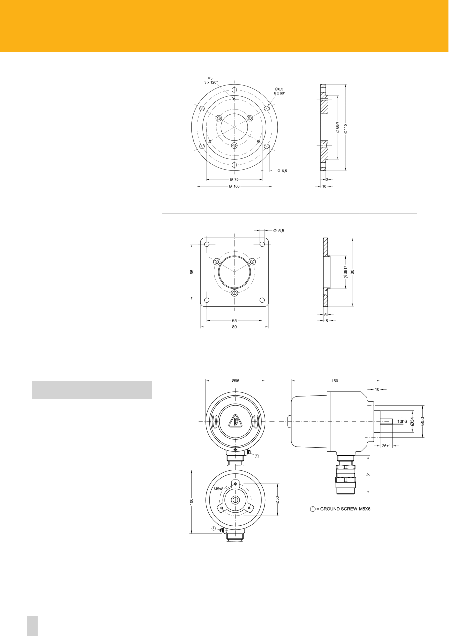
77
www.lika.biz
ROTAPULS
•
ROTACOD
Accessories
REO444 adapting flange
Combine with I58S, I65, Ax58S
Encoder housing according to EEx d IIB + H2T6
LKM-458
LKM-205
EEx HOUSING
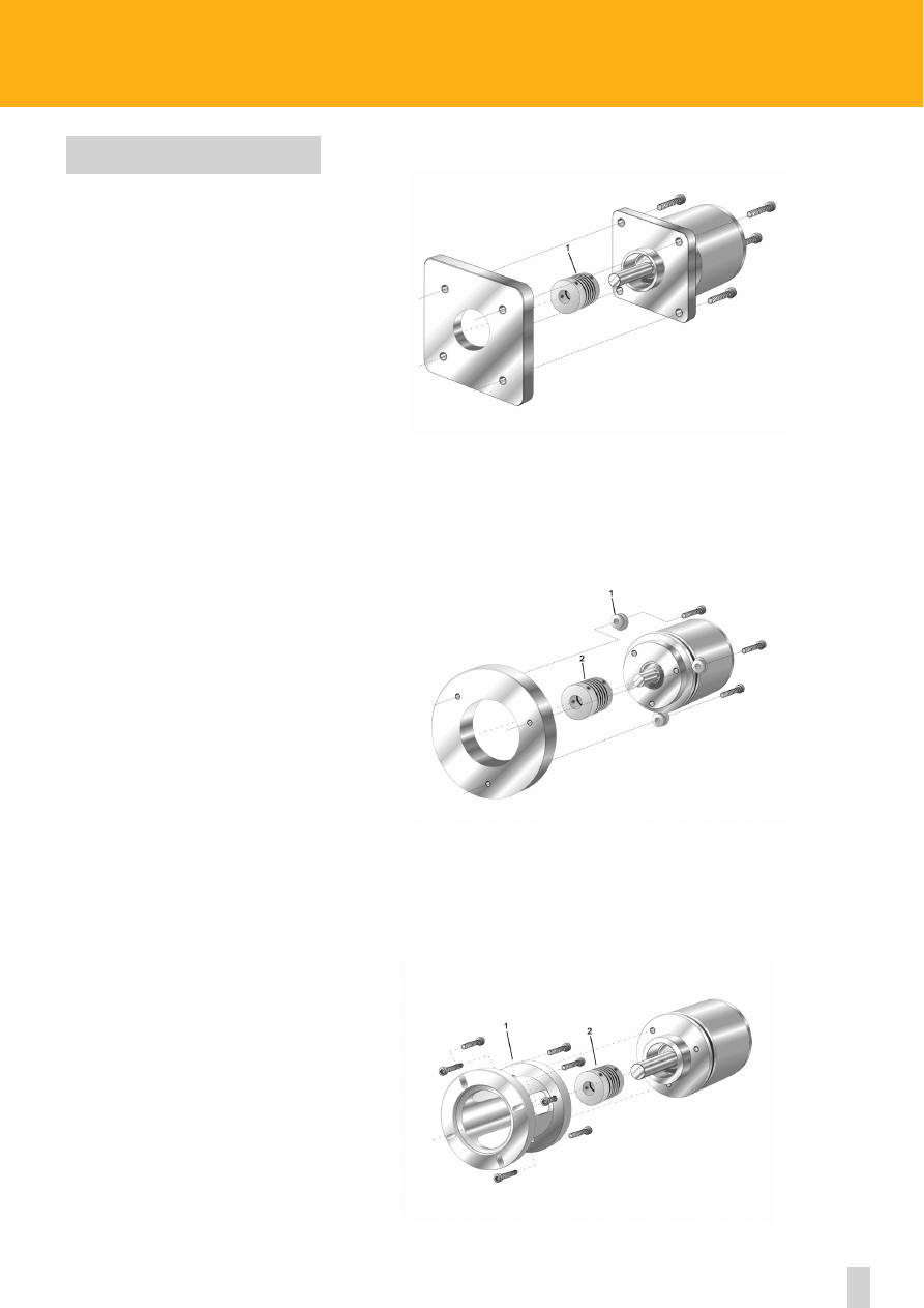
78
MOUNTING OF SOLID SHAFT
ENCODERS
ROTAPULS
•
ROTACOD
Mounting instructions
a) with screws
(1) flexible coupling
b) with fixing clamps (ordering code LKM 386)
(1) fixing clamps kit (LKM 386, supplied with screws)
(2) flexible coupling
c) with mounting bell
(1) mounting bell (ordering code LKM 531)
(2) flexible coupling
www.lika.biz
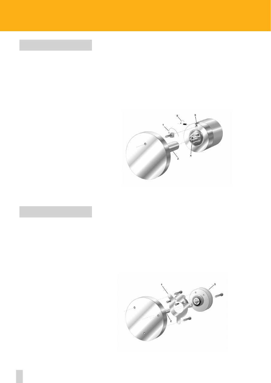
79
www.lika.biz
ROTAPULS
•
ROTACOD
Mounting instructions
MOUNTING OF
C58, CK46 AND CK58 SERIES
Through hollow shaft encoders with fixing plate for direct mounting on motor shafts.
- Screw fixing plate (1) on the back side of the motor;
- Put encoder on motor shaft (2);
- Place encoder at a correct distance from the motor in order to avoid deformation of the fixing plate;
- Fix grub screws/collar (3) of encoder shaft (glueing of screws is suggested).
The fixing plate must allow encoder to move radially in order to absorb misalignment between motor
shaft and encoder shaft. Fixing plates (1) are assembled on encoders.
Hollow shaft encoders for direct mounting on motor shafts.
- Fix antirotation pin (1) on the back side of the motor (lock nut fixing is suggested);
- Put encoder on motor shaft (2);
- Place antirotation pin in the milling on encoder flange (3);
- Fix grub screws/collar (4) of encoder shaft (glueing of screws is suggested).
The antirotation pin (spring loaded) must allow encoder to move radially in order to absorb
misalignment between motor shaft and encoder shaft.
Encoders are supplied with adjusted and glued grub screw (5).
MOUNTING OF
C50, Cx59, Cx60 AND C8x SERIES

Brasil
Canada
China
Denmark
Finland
France
Germany
Greece
Hong-Kong
Iran
Israel
Italy
Mexico
Norway
Poland
Portugal
South Africa
South Corea
Spain
Sweden
Taiwan
Thailand
Turkey
United Kingdom
USA
Lika Electronic is present
in the following countries:
www.lika.biz > contact
Local distributor
Headquarters & Plant
Lika Electronic
Via S. Lorenzo, 25
36010 Carré (VI) ITALY
Tel. +39 0445 382814
Fax +39 0445 382797
eMail info@lika.it
www.lika.it
Ufficio Bologna
Tel. 051 863445
Fax 051 863955
eMail info@lika.it
Ufficio Milano
Tel. 02 93901210
Fax 02 93901522
eMail info@lika.it
Ufficio Torino
Tel. 011 9032762
Fax 011 9020282
eMail info@lika.it
German Branch
Lika Electronic GmbH
Fritz-Reichle-Ring, 18
78315 Radolfzell (D)
Tel. +49 (0) 7732 9423713
Fax +49 (0) 7732 9423718
eMail info@lika-electronic.de
www.lika-electronic.de
Contact...
Wyszukiwarka
Podobne podstrony:
cnc w 3 budowa obrabiarek cnc
22 wiertnice i akcesoria drillto
30 Rozpoznawanie okuć, akcesoriów i łączników
nabożeństwo dzieci komunijnych, I Komunia Św. - pomoce, akcesoria itp, I Komunia święta
Projekt ABB, CNC
7---Karta instrukcji obróbki cieplnej, OPERATOR CNC, TECHNOLOG CNC, KARTY TECHNOLOGICZNE
Komentarz- ofiarowanie darów, I Komunia Św. - pomoce, akcesoria itp, I Komunia święta
11 Operacje, CNC, wycinanie
Akcesoria kosmetyczne
CNC
Badanie dokładności geometrycznej obrabiarki CNC FV 580A z zastosowaniem testu QC10
CNC DROGOSZ 1
sciaga CNC duża
Akcesoria wspomagające higienę jamy ustnej
ver 10 rozkad urzadzenia i systemy wytw cnc
Generating CNC Code with Edgeca Nieznany
Preparaty chemiczne i akcesoria do czyszczenia
więcej podobnych podstron