APP
Project
Original reference
Pl
ot
d
at
e:
1
7.
8.
2007
CREATOR
REV DATE
part or whole without written permission is prohiblited.
Drawing No.
Rev.
A1
Lang.
Eng 1/2
Sheet
New
Item code
Old
NB
Yard
Product
Mark, Size, Type
Appr.
Check.
Drawn
Date
Weight (kg)
Scale
EN ISO 13920-BF
ISO 2768-mL
General tolerance
C
B
D
E
F
G
H
J
K
L
M
A
A
B
C
D
E
F
G
H
J
K
L
6
5
4
3
2
7
8
9
10
11
12
13
14
15
1
1
15
14
13
12
11
10
9
8
7
2
3
4
5
6
16
6780
property of Steerprop Ltd. any reproduction or disclosure in
The information contained in this document is the sole
REVISION NOTE
REV
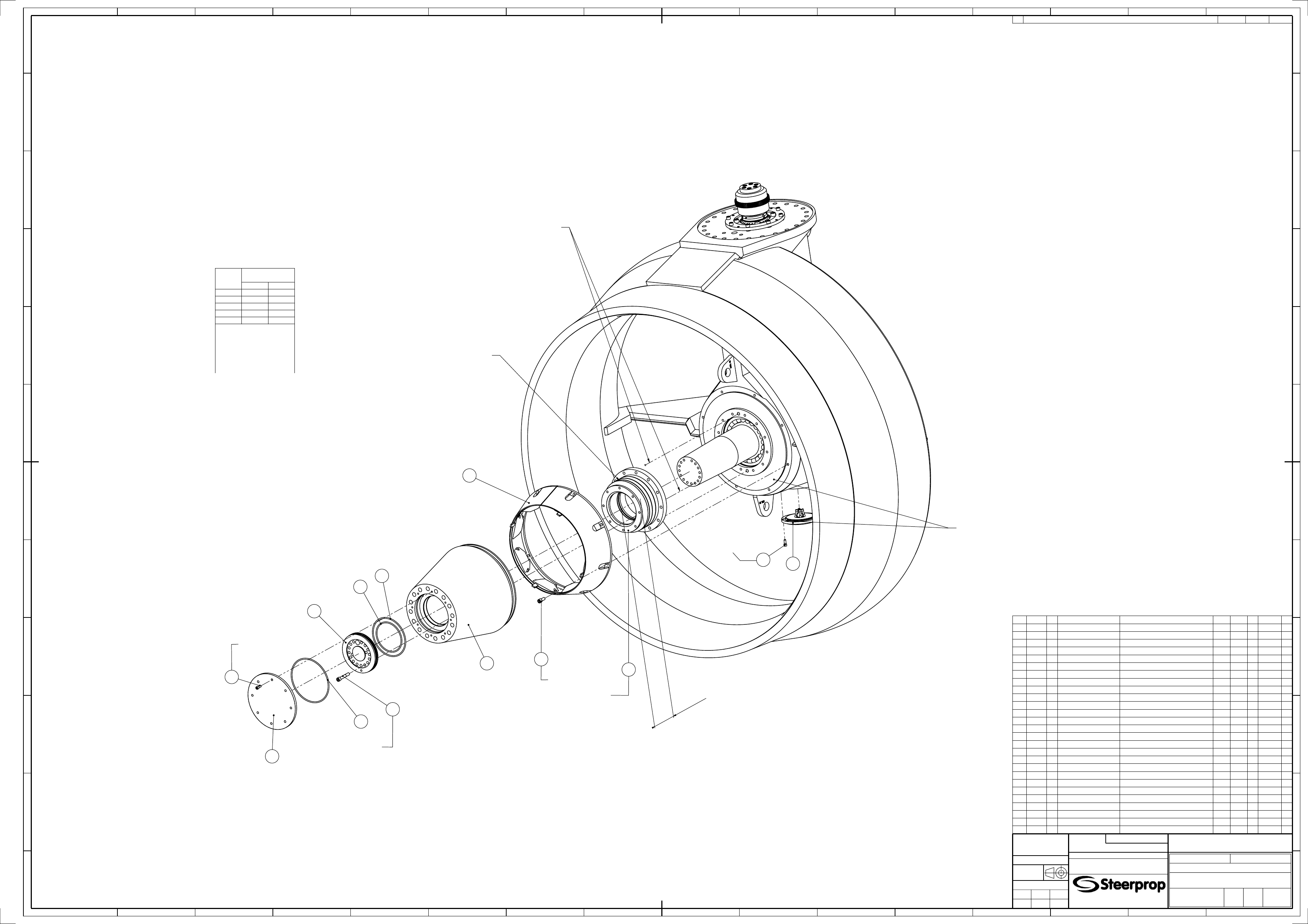
S P - A 1 V
SP 20 D
General arrangement
Lower assembly
2007-01-30
JYVA
A
P000724
W0064-89
004114
MAMA
MAMA
1:10
ITEM
CODE
VER DESCRIPTION
TECHNICAL DATA
DRAWING
REV
QTY
LENGTH WIDTH
1
004110 0
Lower preassembly
Lower assembly
P000722 A
1
2
004099 0
Pinion assembly
Lower assembly
P000716 A
1
3
002418 1
Propeller shaft assembly
Lower assembly
M001807 B
1
4
002127 0
Inspection opening cover
Lower assembly
M001352 A
1
5
002413 0
Pin
Lower assembly
M001760 A
1
6
001519 0
Nut
Lower assembly
M000563 A
1
7
002311 0
Protective cap
Lower assembly
M001651 A
1
8
002336 1
Rope guard
Lower assembly
M001685 B
1
9
002325 0
Propeller hub
Lower assembly
M001679 A
1
10
002319 0
Mounting flange
Lower assembly
M001671 A
1
11
002318 1
Cover
Lower assembly
M001659 B
1
12
002288 0
Tempered washer
M16
M001632 A
24
13
002254 0
Shim plate
M16
M001544 A
8
14
003929 0
Propeller shaft sealing
IHC TS4-240-A-D-O-P TNA13466
1
15
002071 0
Hexagon socket head screw
DIN 912 - M16x50 - 8.8 Zn
8
16
002246 0
Hexagon socket head screw
DIN 912 - M16x70 - 8.8 Zn
24
17
002444 0
Hexagon socket head screw
DIN 912 - M16x100 - 8.8 Zn
15
18
001286 0
Hexagon socket head screw
DIN 912 - M12x30 - A4-80
12
19
001282 0
Hexagon socket head screw
DIN 912 - M16x40 - A4-80
8
20
002445 0
Hexagon socket head screw
DIN 912 - M16x90 - A4-80
12
21
001546 0
Hexagon head screw
DIN 933 - M20x30 - A4-80
2
22
002078 0
Set screw
DIN 916 - M24x25
1
23
002446 0
O-ring
189,87x7,00 NBR 90 Shore (Moulded ring)
1
24
002447 0
O-ring
253,37x7,00 NBR 90 Shore (Moulded ring)
1
25
001603 0
O-ring
266,07x6,99 NBR 70 Shore (Moulded ring)
1
26
001963 0
O-ring
730x7,00 NBR 70 Shore (Moulded ring)
1
27
001601 0
O-ring
850x7,00 NBR 70 Shore (Moulded ring)
1
Gravity line bores in line
14
8
19
9
10
24
23
17
25
11
18
4
59 Nm
206 Nm
145 Nm
59 Nm
Mounting dimension
manufacturers instructions
Mounting according to
18
Sealing glue
Sealing glue
202
±4
NOTE! This assembly for RIGHT HANDED propeller.
Locking of screws according to instruction M000416.
- Gear R = 319 mm
Torsional flank play of gears 0,30 . . . 0,35 mm.
Measuring distance R from shaft centerline:
- Pinion R = 115 mm
Weight without propeller
Assembly
NiAl-propeller
temperature Pull up
t /ºC
Min.
Max.
-40
6,64
6,84
-20
6,16
6,36
0
5,68
5,88
20
5,20
5,40
40
4,72
4,92
Pull up
start load:
75 kN
Corresponding screw tightening
torque:
14 Nm
Corresponding piston hydraulic
pressure:
34 bar
Project
Original reference
Pl
ot
d
at
e:
1
7.
8.
2007
The information contained in this document is the sole
property of Steerprop Ltd. any reproduction or disclosure in
part or whole without written permission is prohiblited.
Drawing No.
Rev.
A1
Lang.
Eng 2/2
Sheet
New
Item code
Old
NB
Yard
Product
Mark, Size, Type
Appr.
Check.
Drawn
Date
Weight (kg)
Scale
EN ISO 13920-BF
ISO 2768-mL
General tolerance
C
B
D
E
F
G
H
J
K
L
M
A
A
B
C
D
E
F
G
H
J
K
L
6
5
4
3
2
7
8
9
10
11
12
13
14
15
1
1
15
14
13
12
11
10
9
8
7
2
3
4
5
6
16
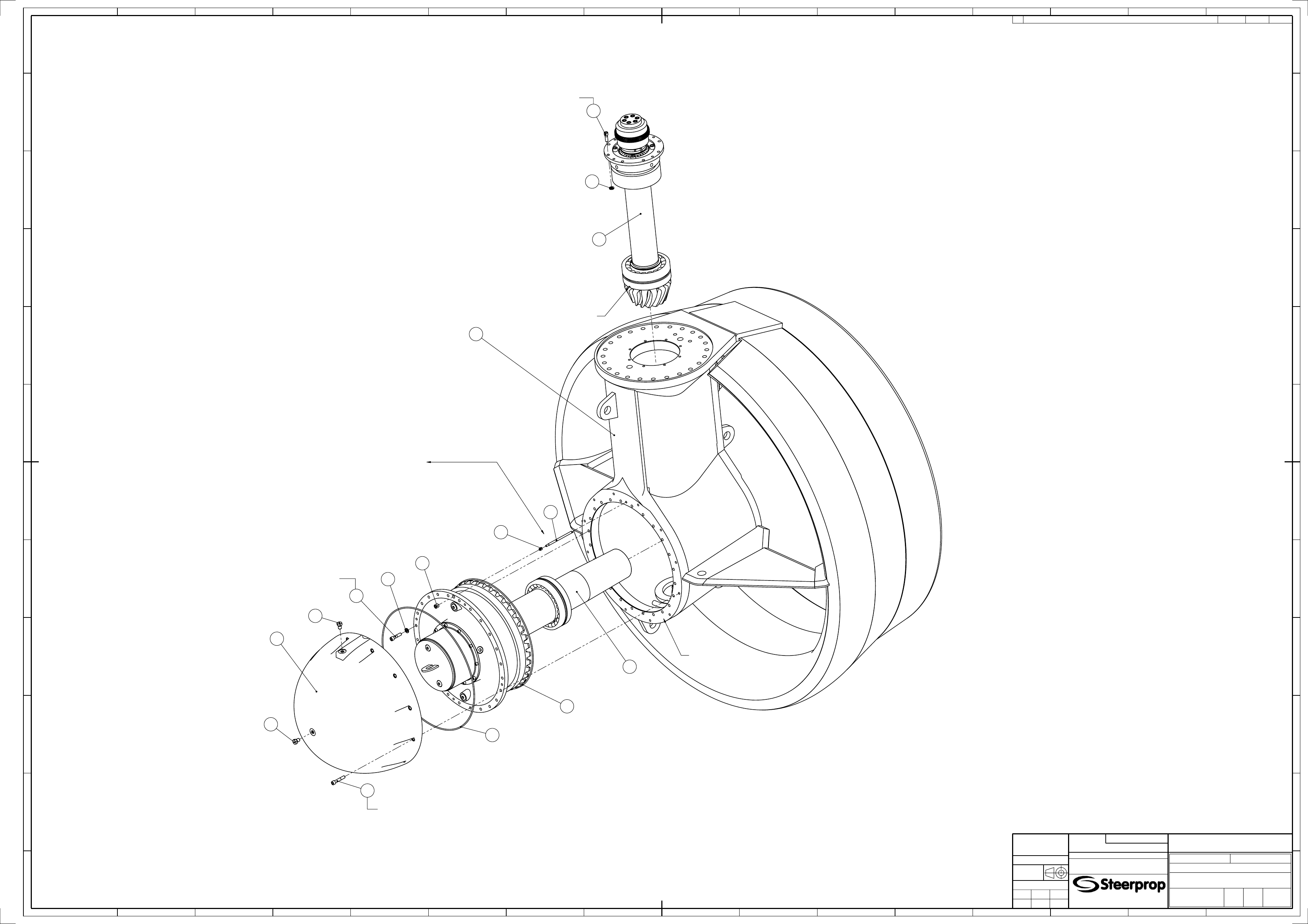
P000724
A
JYVA
2007-01-30
Lower assembly
General arrangement
SP 20 D
S P - A 1 V
1:10
MAMAMAMA
004114
W0064-89
REV
REVISION NOTE
REV DATE
CREATOR
APP
1
3
2
7
5
6
22
12
16
20
21
21
27
26
15
13
Locking of pinion bearing outer ring:
Notice! Locking after flank contact adjustment.
1. Pin (item 5) is pushed against bottom of groove on
bearing outer ring.
2. Nut (item 6) is screwed on pin gently against lower body.
3. Gap between pin and groove bottom is adjusted to correct
width by tightening the nut a further 2/3 revolution.
4. The nut is fastened with Loctite.
5. After fastener has hardened, set screw (item 22) is tightened
against nut and fastened with Loctite.
Groove in the bearing outer ring
for the locking pin
145 Nm
206 Nm
206 Nm
Sealing glue
Wyszukiwarka
Podobne podstrony:
P000722 A Eng Lower preassembly
M001882 B Eng Lower assembly
P000720 D Eng Upper assembly
M001886 B Eng Lower assembly
P000729 D Eng Upper assembly
P000720 C Eng Upper assembly
P000722 A Eng Lower preassembly
M001882 B Eng Lower assembly
P000726 A Eng Stem tube assembly
więcej podobnych podstron