T
he beast needed a hefty battery for power, and with
the battery alone weighing some 15 pounds, I
needed a sturdy frame to keep everything together.
Constructed of aluminum, the robot measured 18
inches square by almost three feet high, and required heavy
duty and expensive gear motors — all this just to meander
down the hallway and scare the &@%! out of my cat.
Five years and over $1,500 later, I put “Maximillian” to
rest, pulling its parts to use in other projects. Robot
electronics were shrinking, and that meant robots
themselves were getting smaller. Innovations like the BASIC
Stamp made it much easier to experiment with low cost,
self-contained microcontrollers — perhaps the ideal robotic
brain. Microcontrollers are now so commonplace that you
have your pick of hundreds of makes and models; from the
super simple, to the confoundedly complex. Somewhere in
the middle is the Arduino — a small and affordable
microcontroller development board that’s fast becoming
something of a superstar.
Why the Popularity?
Sure, the Arduino is a capable little critter able to
handle the most common things microcontrollers can do.
And let’s not forget that some of its fame has to do with
price: the standard Arduino costs about $30, assembled
and tested. Even less if you want to build it from a kit.
Then there’s its free programming software. Using a
standard USB cable, it lets you easily connect the Arduino
to your computer — Windows, Mac, or Linux — and begin
working in minutes. The programming editor is simple to
use and comes with several dozen examples to get you
started.
What’s really made the Arduino a darling of geeks the
world over is this: Both its hardware design and software
are open source. That means others are able to take the
best ideas and improve on them, all without paying
licensing fees. This has created something of a cottage
industry of fans and third-party support.
Though the most popular version of the Arduino is
made by a company in Italy (where the board was originally
developed), many others offer compatible designs in one
form or another. Add to this a growing body of add-ons
that maximize the Arduino, and free resources for
programming examples, code libraries, and step-by-step
tutorials.
Making Robots
With The
56
SERVO 11.2010
Twenty years ago, I began work on my ultimate home robot. Its brain was
an Intel 80286-based PC motherboard, running at a whopping 8 MHz. The
robot used a floppy disc drive to load the operating system and programs,
and custom prototype boards for external interfacing.
A
rduino
Part 1
By Gordon McComb
worldmags
worldmags
Introducing Arduino Robotics
So, it makes sense to look at ways to leverage the
Arduino to build robots. That’s exactly what we’ll be doing
in this article and several more to follow in the months
ahead. I’ll show you how to build, program, and use an
economical and expandable autonomous desktop robot
— the ArdBot — that’s powered by an Arduino. Cost of the
project is under $85 — even less if you already have some
basic components like a solderless breadboard and hookup
wire.
The robot base is simple to build and can be
constructed out of a variety of materials; no special tools
are required. I’ll demonstrate a version made of expanded
PVC plastic, but you can use heavy cardboard, foam board,
picture frame mat board, or most any other material you
like. (For your convenience, you can get the robot chassis
precut with all the hardware; see the Sources box for more
information.)
I believe in robot designs that let you explore and
experiment, and the ArdBot leaves plenty of room for
expansion and independent discovery. You can use the
robot for line or wall following, maze solving, or general
meandering around in a room. (Cat scaring optional.) You
can also take the concepts presented here and design your
own version of the ArdBot — bigger or smaller, wheels or
tracks — your choice.
In this installment, you’ll learn all about the Arduino:
what it’s made of, how to connect it to your computer, and
how to start developing robot projects for it. You’ll also be
introduced to the ArdBot chassis, including where to get its
main parts. In coming installments to this series, you’ll
explore programming the robot to do interesting things,
and extending its features with sensors and other add-ins.
Arduino Under the Hood
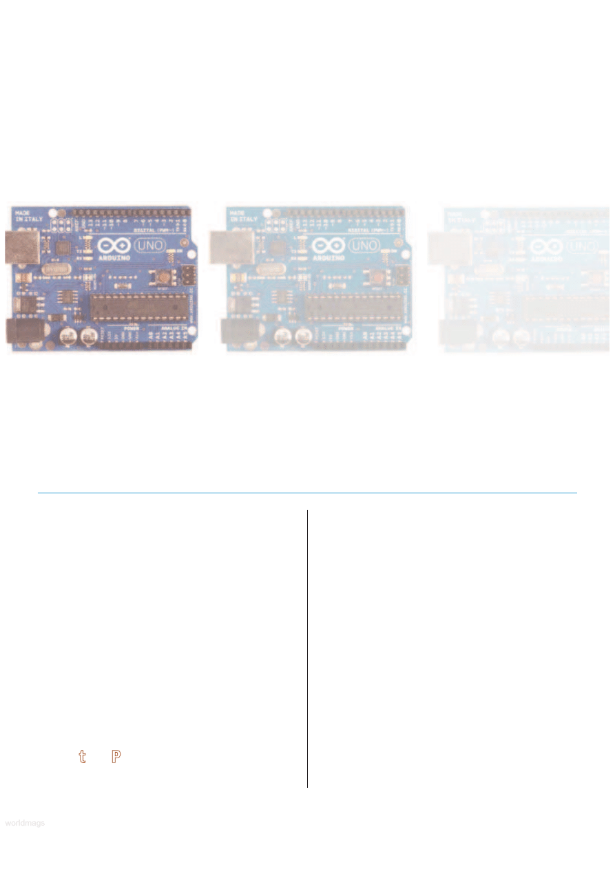
First introduced in 2005, the Arduino has gone through
numerous iterations, revisions, and
improvements. As I’m writing this, the
Arduino team just released their newest
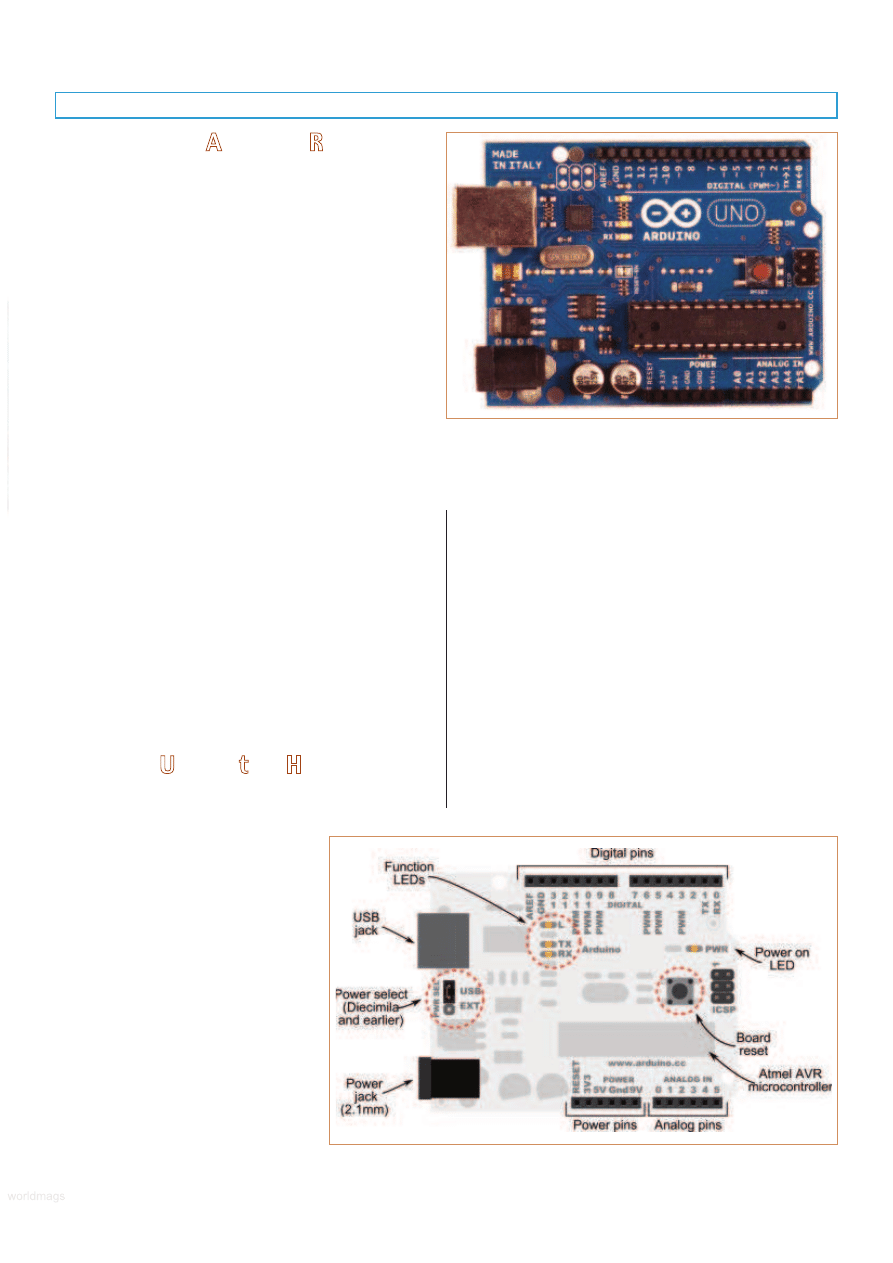
version: the Arduino Uno (see Figure 1).
Like its predecessors, the Uno is an all-in-
one development board. It contains an
Atmel AVR microcontroller — specifically
the ATmega328 — a USB-to-serial
interface, five volt voltage regulator, and
various support electronics.
Previous iterations of the Arduino
have included the Duemilanove (which
means 2009 in Italian) and the Diecimila
which means 10,000 (a reference to the
number of Arduino boards that had been manufactured by
that time; many more have been made since).
The Uno, Duemilanove, and Diecimila are what might
be called main or core board designs. These all share a
common form factor which is a PCB that measures 2-1/8”
by 2-3/4”. All contain a power jack for a 2.1 mm (center
positive) barrel connector, as well as a USB Type B jack for
hooking up to a host computer.
A series of 28 female pin headers allow connection of
external devices to the Arduino. The headers are separated
into three groups as shown in Figure 2. The groups are:
power, analog input, and digital input/output. Of the 28
pins, 20 are devoted to input and output. There are six
analog input pins which can also serve as general-purpose
digital I/O. The 14 digital input/output pins include six that
can be used to generate PWM (pulse width modulated)
signals; these are useful for such things as controlling the
SERVO 11.2010
57
FIGURE 2.
Points of interest on the Arduino
board include the USB and power jacks,
function and power LEDs, and rows of
connection headers.
FIGURE 1.
The Arduino Duo is a compact microcontroller board
based on the Atmel ATmega328 chip. It’s available from a
number of sources at about $30 average retail.
www.servomagazine.com/index.php?/magazine/article/november2010_McComb
worldmags
worldmags
worldmags
speed of motors. Through its I/O pins, the Arduino
supports the basic inter-communications standards: TTL
serial, SPI, 1-Wire, and I
2
C. Two of its pins (digital I/O lines
2 and 3) support hardware interrupts that via software
trigger on a LOW value, a rising or falling edge, or a
change in value.
Like any microcontroller, the Arduino is basically a small
single-board computer designed to interface to external
hardware like switches, motors, lights, relays, sensors, and
LEDs. At the heart of the Arduino is an Atmel AVR
microcontroller. The exact version of AVR controller
depends on the version of the Arduino. For example, the
older Diecimila and the first Duemilanove versions used an
AVR ATmega168; the second generation Duemilanove
(referred to as 2009b) as well as the Uno, use the AVR
ATmega328. The ‘328 is physically identical to the ‘168 but
it contains more memory space. See Tables 1 and 2 for
details on variations between the controller chips used.
The bulk of the components on the Arduino are
surface-mount, but on most Arduino boards the AVR
microcontroller is provided in a dual inline pin (DIP)
package. This permits easy replacement should that ever be
needed. A new AVR chip costs maybe $5 or $6; that’s a lot
cheaper than replacing the entire Arduino board.
Keep in mind that the AVR provided in commercially
manufactured Arduino boards comes with a bootloader
program pre-installed in its Flash memory. This bootloader
allows you to program the Arduino by using a USB
connection to your PC. When replacing the AVR
microcontroller of an Arduino, you need to either purchase
a chip with the bootloader software pre-installed, or if you
have the proper hardware setup — like an Atmel STK500
programmer — you can do it yourself. Instructions for
downloading bootloader software into an AVR chip are
provided on the main Arduino information page.
Many Variations on a Theme
The core board designs of the Uno, Duemilanove, and
Diecimila are perhaps the most common and popular of the
Arduinos, but there are numerous other variations. Here are
just some of the standardized Arduino boards you’ll
encounter. The Arduino BT and Fio are intended for wireless
applications. The BT contains a Bluetooth module; the Fio
has a built-in Zigbee radio. (You can also readily add
Bluetooth and Zigbee to an Uno or other core board using
“shields” detailed below.)
The Nano is a compact stick-shaped board made for
breadboard use. It has all the main features of the Uno and
others (including built-in USB jack), but measures only 0.73”
x 1.7”. It uses only surface-mount parts.
The Mini is even smaller, and is ideal for very small bots
with limited space. The Mini lacks its own USB jack, and
requires the use of a USB adapter or serial TTL connection
to the host PC for programming. The Mini has four analog
input pins instead of the six or eight of the other versions.
The Mega2560 is based on a larger AVR chip, and it
offers over three times the number of analog and digital
I/O lines (see Table 3). Memory and program space are
bigger, too. The Arduino Mega2560 contains 256 KB of
Flash (by comparison, the Uno has 32 KB), as well as more
RAM and EEPROM space. Use this for the bigger jobs.
Several Arduino resellers (such as Solarbotics and
Adafruit) offer their own custom offshoots of the Arduino
— these typically go by different names such as Boarduino
58
SERVO 11.2010
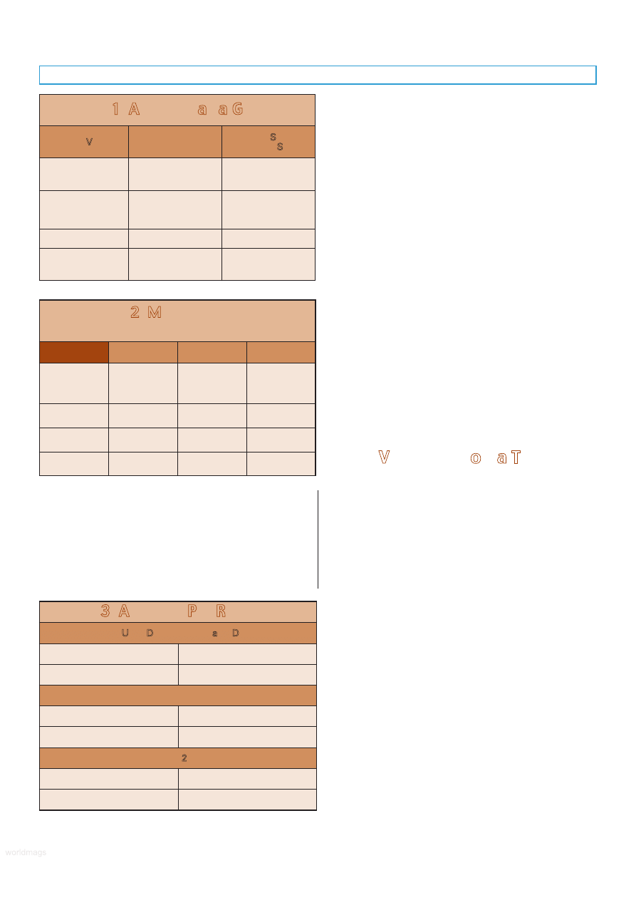
Table 1. Arduino at a Glance.
Arduino Version
Microcontroller
Supports Standard
Expansion Shields
Uno and
Duemilanove
(2009b)
ATmega328
Yes
Duemilanove
(pre-2009b) and
Diecimila
ATmega168
Yes
Mega 2560
ATmega2560
No
Nano, Mini,
LilyPad, others
ATmega168 or
ATmega328
No
Table 2. Microcontroller
Specifications.
ATmega168
ATmega328
ATmega2560
Flash memory
16 KB; 2 KB
used by
bootloader
32 KB; 0.5 KB
used by
bootloader
256 KB; 8 KB
used by
bootloader
SRAM
1 KB
2 KB
8 KB
EEPROM
512 bytes
1 KB
4 KB
Clock speed
16 MHz
16 MHz
16 MHz
Table 3. Arduino Pin Resources.
Arduino Uno, Duemilanove, and Diecimila
Digital I/O Pins
14 (of which six provide
PWM output)
Analog Input Pins
6
Nano
Digital I/O Pins
14 (of which six provide
PWM output)
Analog Input Pins
8
Mega 2560
Digital I/O Pins
54 (of which 14 provide
PWM output)
Analog Input Pins
16
worldmags
worldmags
worldmags
worldmags
or Freeduino to differentiate them from the original Arduino
designs. The Adafruit Boarduino (available in kit form for
under $18) is like the Arduino Nano. It uses thru-hole
components for ease of soldering.
Some variations of the Arduino depart from the
standard form-factor of the Uno, and are not designed for
use with expansion shields (discussed below). A good
example is the LilyPad — a special Arduino layout
engineered for making (among other things) wearable
microcontroller projects. Think Borg implants, only more
friendly looking. The flower-shaped LilyPad has a flat profile
and can be sewn into fabric. It has connection points on
the ends of its 22 petals.
With so many variations of the Arduino floating
around, it’s easy to get confused. For the ArdBot, we’ll be
using an Arduino Duo, but you can readily substitute just
about any of the other versions. If you already have an
earlier Duemilanove or even Diecimila, you can use it with
the ArdBot. The only catch is that you’ll need to make sure
you have an up-to-date Arduino programming environment
installed on your computer. I’ve tested everything with
version 0019 of the Arduino programming IDE (discussed
later), so with that version or anything later you should be
good to go.
Ready Expansion Via Shields
The Arduino is an example of the KISS principle. Its
simple design helps keep costs down, and makes the
Arduino a universal development board adaptable to just
about anything. While there are more expensive specialty
versions of the Arduino made for robotics applications, the
basic board lacks connectors to directly attach to motors,
sensors, or other devices.
The Arduino itself has no breadboard area, but it’s easy
enough to connect any of the inputs or outputs to a small
breadboard via wires. For an application like robotics, you’ll
want to expand the Arduino I/O headers to make it easier
to plug in things like motors, switches, and ultrasonic or
infrared sensors.
One method is to use an add-on expansion board
known as a shield. These stick directly on top of the core
board designs (Uno, Duemilanove, and Diecimila). Pins on
the underside of the shield insert directly into the Arduino’s
I/O headers. Two popular expansion shields are the
solderless breadboard and the proto shield; both provide
prototyping areas for expanding your circuit designs.
Of course, you don’t absolutely need a shield to expand
the Arduino. You can place a breadboard — solderless or
otherwise — beside the Arduino, and use ribbon cables or
hookup wire to connect the two together. This is the
approach we’ll be using with the ArdBot described in this
series of articles.
USB Connection and Power
To allow the easiest possible means of programming,
the Arduino Duo and related core boards support on-board
USB. You merely need to connect a suitable USB cable
between the Arduino and your computer. The cable even
provides the power to the board. The necessary USB drivers
are provided with the Arduino software. In most cases,
installation of the drivers is not fully automatic, but the
steps are straightforward and the Arduino support pages
provide a walk-through example.
The Arduino accepts a standard USB Type B connector.
Your PC probably uses the larger Type A connector, so you
need a Type A to Type B USB cable. Keep in mind that
some PCs and laptops may use Mini-A or Mini-B connectors,
so check first before purchasing a cable for use with the
Arduino.
Operating voltage of the Arduino circuitry is five volts
which is supplied either by the USB cable when it’s plugged
into a USB port on your computer, or by a built-in linear
regulator when the board is powered externally. The
regulator is intended to be powered by 7-12 VDC; a nine
Main Components
This is a selected list of North American sources for the
main components for the ArdBot.
Arduino Duo or Duemilanove
Source
Item or SKU
Adafruit
50
HVW Tech
28920 (Freeduino SB)
RobotShop
RB-Ard-03
SparkFun
DEV-09950
Solderless breadboard, 170 tie-points
Source
Item or SKU
Adafruit
65
HVW Tech
21380
Parallax
700-00012
RobotShop
RB-Spa-139
Continuous rotation servo (Futaba spline)
Source
Item or SKU
Parallax
900-00008
Pololu
1248
RobotShop
RB-Gws-23
Solarbotics
36000
SparkFun
ROB-09347
2-1/2” or 2-5/8” rubber wheels
(Futaba spline)
Source
Item or SKU
Adafruit
167
HVW Tech,
Solarbotics
SW
Parallax
28109
Pololu
226
RobotShop
RB-Sbo-86
SERVO 11.2010
59
worldmags
worldmags
worldmags
volt battery is ideal. Anything higher than 12 volts is not
recommended as it could cause the regulator to overheat.
For robotics, I think it’s best to power the Arduino from
its own battery. The ArdBot uses a split supply where the
Arduino is powered by a nine volt transistor battery; a
separate four-cell AA battery holder is used for servo
motors and other components that don’t require voltage
regulation.
Indicator LEDs are provided on the Arduino for testing
and verification. A small green LED shows power; two other
LEDs show serial transmit and receive activity and should
flash when the board is being programmed from your
computer. A fourth LED is connected in parallel with digital
I/O line 13 and serves as a simple way to test the Arduino
and make sure it is working properly. We’ll use this feature
in a simple example later on in this article.
Programming the Arduino
Microcontrollers depend on a host computer for
developing and compiling programs. The software used on
the host computer is known as an integrated development
environment, or IDE. For the Arduino, the development
environment is based on the open source Processing
platform (www.processing.org) which is described by its
creators as a “programming language and environment for
people who want to program images, animation, and
interactions.“
The Arduino programming language leverages an open
source project known as Wiring (wiring.org.co). The
Arduino language is based on good old-fashioned C. If you
are unfamiliar with this language, don’t worry; it’s not hard
to learn, and the Arduino IDE provides some feedback
when you make mistakes in your programs.
60
SERVO 11.2010
FIGURE 3.
The Arduino integrated development environment (IDE)
provides a centralized place to write, compile, and download
programs to the Arduino board.
Adafruit Industries
www.adafruit.com
Arduino resellers and custom shield projects. Convenient
premade nine volt battery clip and 2.1 mm barrel connector
(see product #80), and nine volt battery holder with switch
(product #67).
Arduino
www.arduino.cc
The main Arduino site provides downloads, tutorials,
references, design schematics, and other information useful
for learning about and using the Arduino family of boards.
Atmel
www.atmel.com/products/AVR
Manufacturers of the AVR microcontrollers used in the
Arduino. See their site for datasheets (in PDF format).
Budget Robotics
www.budgetrobotics.com
Custom machined decks, servo mounting hardware, and
assembly hardware for the ArdBot.
Freeduino
www.freeduino.org
Home of the Freeduino collaborative project.
HVW Technologies
www.hvwtech.com
Reseller of Arduino products and manufacturer
(with Solarbotics) of the Freeduino SB.
Parallax
www.parallax.com
Not resellers of Arduino, but they offer continuous rotation
servos, wheels, and sensors.
Pololu
www.pololu.com
Wheels, continuous rotation servo motors.
RobotShop
www.robotshop.ca (Canada); www.robotshop.us (US)
Full service retailer carrying most all of the official
Arduino lineup, plus servo motors, solderless breadboards,
and sensors.
Solarbotics
www.solarbotics.com
Continuous rotation servos, five-cell AA battery packs
with attached 2.1 mm barrel connector, Arduino, and
Arduino-clone boards.
SparkFun Electronics
www.sparkfun.com
Reseller of the Arduino and manufacturer of custom
Arduino-like hardware.
Sources
worldmags
worldmags
worldmags
If you’ve dabbled in Basic, you just need to remember
that in C, keywords and variables are case sensitive. Instead
of using If/End If, in C, code blocks are grouped together
using the { and } (brace) characters. Statements are
terminated with a ; (semi-colon) character, rather than just a
simple line break. Any other differences, you’ll pick up
quickly.
To get started with programming your Arduino, first go
to: http://arduino.cc and then click on the Download tab.
Find the platform link (PC, Mac, Linux) for your computer
and download the installation file. Step-by-step instructions
are provided in the Getting Started section of the Arduino
website. Be sure to read through the entire instructions.
Be aware that the main Getting Started section
assumes you’re using an Arduino Uno, Duemilanove, Nano,
or Diecimila board. If you’re using another version of the
Arduino, be sure to check out its corresponding page on
the site.
Once installation is complete, you’re ready to try out
your Arduino. Start by connecting the board to your PC via
a USB cable. If this is the first time you’ve used an Arduino
on your PC, you must install the USB communications
drivers, as detailed in the Getting Started guide.
Using the Arduino programming environment is simple.
First-time use of the environment requires you to specify the
Arduino board you are using, and as necessary, the serial
port that is connected to the board (the Arduino’s USB
connection looks like a serial port to your computer). You
may then open an existing example program which is called
a sketch in Arduino parlance, and download the program to
your board. Or, you may write your own sketch in the IDE
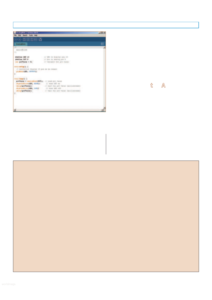
editor. Figure 3 shows the Arduino IDE with a short sketch
in the main window.
After writing or opening an existing sketch, you need
to compile it which prepares the code for downloading to
the Arduino. The Arduino IDE calls compiling a program
verifying. At the bottom of the text editor is a status
window which shows you the progress of compiling
(verifying). If the sketch is successfully compiled, it can then
be downloaded to the Arduino where it will automatically
run once the download is complete.
Programming for Robots
As you go through the list of programming statements
available in the Arduino IDE (choose Help->Reference), you
might think there isn’t much power for doing things like
running servos, operating stepper motors, reading
potentiometers, or displaying text on an LCD.
Like most any language based on C, the Arduino
supports the notion of “libraries” — code repositories that
extend core programming functionality. Libraries let you
re-use code without having to physically copy and paste it
into all your programs. The standard Arduino software
installation comes with several libraries you may use,
and you can download others from the Arduino support
pages and from third-party websites that publish
Arduino library code.
A good example of a library you’ll use with the ArdBot
— and likely many other robot projects — is Servo. This
library allows you to connect one or more hobby R/C servos
to the Arduino’s digital I/O pins. The Servo library comes
with the standard Arduino installation package, so adding it
to your sketch is as simple as choosing Sketch->Import
Library->Servo. This adds the line
#include <Servo.h>
which tells the Arduino IDE that you wish to include the
Servo library in your sketch. With the functionality of the
library now available to you, you can use its various
functions to control one or more servos. For example,
you can use the write function to rotate a servo to a
specific position, from 0 to 180 degrees. The following
code
myServo.write(90);
moves a servo to its midpoint, or 90 degree position.
Structurally, Arduino sketches are very straightforward
and are pretty easy to read and understand. The Arduino
program contains two main parts: setup() and loop(). These
are programming functions that do what their names
suggest: setup() sets up the Arduino hardware, such as
specifying which I/O lines you plan to use, and whether
they are inputs or outputs. The loop() function is repeated
endlessly when the Arduino is operating.
SERVO 11.2010
61
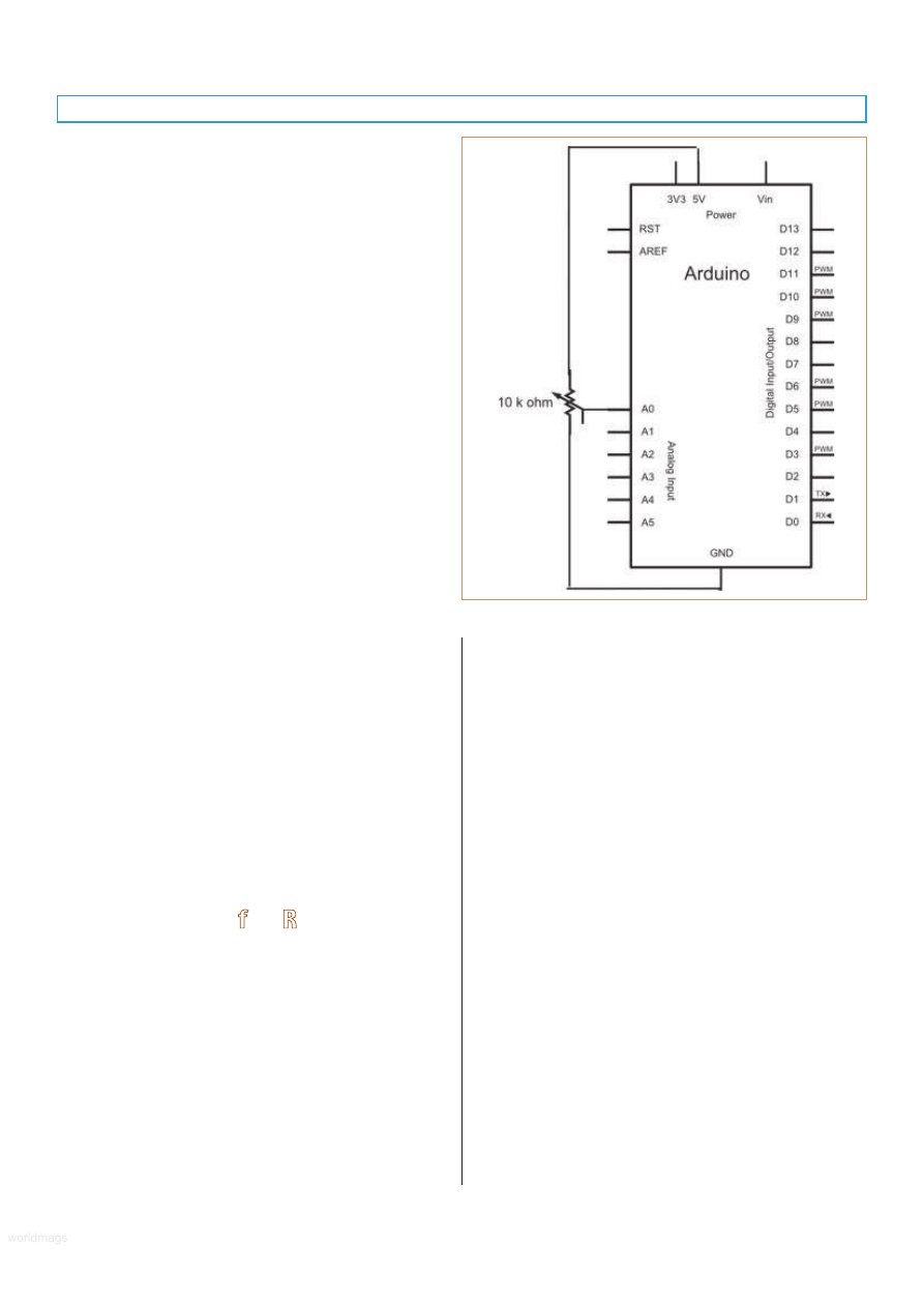
FIGURE 4.
Schematic for
Listing 1
testing
circuit.
worldmags
worldmags
worldmags
Experiment By Doing
Listing 1 demonstrates a few fundamental Arduino
concepts useful in any robotics development — that is,
reading an analog sensor and providing visual feedback.
I’ve taken one of the examples that comes with the
Arduino IDE and modified it slightly to conform to the style
we’ll be using throughout this series of ArdBot articles. It
uses a 10 kΩ potentiometer to alter how fast Arduino’s
built-in LED flashes.
Check out Figure 4 for a schematic of the circuit used
for the program listing; Figure 5 shows a pictorial
breadboard view of connecting the potentiometer to the
Arduino hardware. The potentiometer is connected to the
board as a common voltage divider. That way, the Arduino
detects the value of the pot as a variable voltage from zero
volts (ground) to five volts.
Note that I’m using a standard mini solderless
breadboard with 170 tie-points. The breadboard serves as a
prototyping area for connecting to various hardware, and is
part of the ArdBot. You can use any other size of solderless
breadboard, but none of the circuits for the ArdBot will
require anything bigger.
Here’s how the program works:
The first two lines set variable constants, so hardware
connected to the various I/O pins can be referred to by
name and not pin number. This is merely for our
convenience. The built-in LED is connected to pin 13, and
the potentiometer — named POT in our program — is
connected to analog pin 0.
Another variable is defined to hold the current value of
the potentiometer which will be a number from 0 to 1023.
This number is derived from the Arduino’s integrated 10-bit
analog-to-digital (ADC) converter, and it represents a
voltage level from zero volts to five volts.
The setup() section gets the Arduino hardware ready
for the rest of the program. When first powered on, all the
I/O lines are automatically defined as inputs. The LED pin
needs to be an output, however, so that distinction is
defined here. The programming statement that changes the
function of an I/O line is pinMode. It expects two values
(called arguments): the number of the I/O pin — in this
case, it’s 13 as defined by the LED variable — and whether
the pin is an OUTPUT or an INPUT.
The loop() section is automatically started the moment
the program has been downloaded to the Arduino. The
looping continues until the board is either unplugged, the
reset button on the Arduino is pushed, or a new program is
loaded into memory. The loop begins by reading the
voltage on analog pin 0 — remember, it’s defined in the
POT variable at the top of the program. The program then
turns the LED on, and waits for a period of time defined by
the current position of the potentiometer before turning
the LED off again.
The waiting period is in milliseconds (thousandths of a
second), from 0 to 1023, the range of values from the
Arduino’s ADC. Very fast delays of about 100 milliseconds
or less will appear as a steady light. You’ll be able to see
the LED flash with longer delays.
62
SERVO 11.2010
Listing 1
#define LED 13
// LED to digital pin 13
#define POT 0
// pot to analog pin 0
int potValue = 0;
// variable for pot value
void setup() {
// initialize digital 13 pin as an output
pinMode(LED, OUTPUT);
}
void loop() {
potValue = analogRead(POT);
// read pot
// value
digitalWrite(LED, HIGH);
// turn LED on
delay(potValue);
// wait for pot
value
// (milliseconds)
digitalWrite(LED, LOW);
// turn LED off
delay(potValue);
// wait for pot
value (milliseconds)
}
FIGURE 5.
Breadboard layout for Listing 1 testing circuit. The
potentiometer is 10 kW, linear taper.
worldmags
worldmags
worldmags
Quick View of the ArdBot
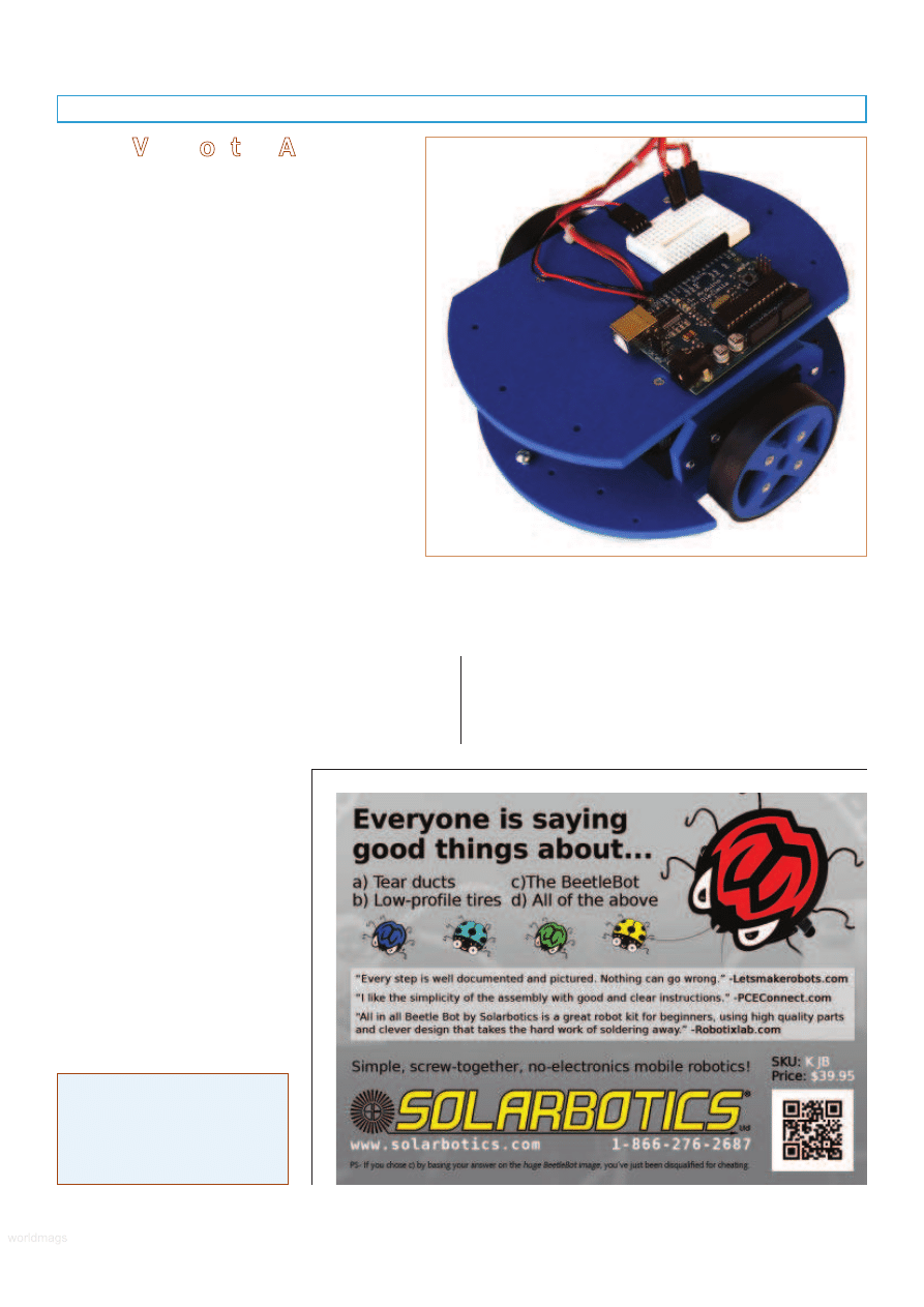
Figure 6 shows the prototype ArdBot, made of
6 mm (about 1/4”) expanded PVC. In the next
installment, I’ll provide detailed construction plans,
but here’s the robot in a nutshell:
• Two 7” “decks” provide generous room for
motors, batteries, Arduino, and mini solderless
breadboard, as well as future expansion. The
top deck is secured by four machine screws to
a set of 1-3/4” long aluminum hex standoffs.
• Two standard size continuous rotation servos
drive the robot using the differential steering
technique where the speed and direction of
each motor determines where the robot travels.
• Half-inch wide tires provide traction indoors and
out. The wheels measure 2-1/2” in diameter,
and directly connect to the servo shafts.
• To keep costs down the ArdBot doesn’t use
wheel casters or ball transfers. Instead is uses
two height-adjustable skids fore and aft which
keep the robot level. The skids have rounded
bottoms and act just like small rollers.
The bottom deck is used for mounting the servos and
battery packs. The deck is large enough for several four- or
five-cell AA battery holders, plus a nine volt cell or custom
battery packs. There’s room in the corners of the deck for
mounting infrared, bump switch, or other sensors.
The top deck provides open access to the Arduino and
solderless breadboard, both of which you can place
anywhere you want. This way, you can program and
reconfigure the board without any
disassembly of the robot. There’s
room for servo turrets,
accelerometers, GPS receivers,
sensor modules, and more. In the
event you need even more room for
your experiments, you can add a
third deck for an additional 35
square inches of space.
The ArdBot is a universal design
with components you can get from
a variety of suppliers. See the
Sources box for a list of online
retailers that sell the Arduino and
other parts. You can build the
ArdBot platform yourself, or if you
don’t like mechanical construction,
as a convenience to SERVO readers, you can get the two
body decks and all mounting hardware from my Internet
company, Budget Robotics.
So much for the basics. See you next time for detailed
constructions plans of the ArdBot and more.
SV
About the Author
Gordon McComb is the author
of Robot Builder’s Bonanza.
He can be reached at
arduino@robotoid.com.
FIGURE 6.
Prototype ArdBot, a double-decker desktop robot
using the Arduino Duo or similar controller board. It’s designed
for easy expansion and experimentation.
Construction will be covered in Part 2.
SERVO 11.2010
63
worldmags
worldmags
worldmags
Wyszukiwarka
Podobne podstrony:
Making Robots With The Arduino part 5
Making Robots With The Arduino part 2
Making Robots With The Arduino part 3
Making Robots With The Arduino part 5
PENGUIN READERS Level 4 Gone with the wind Part 1 (Answers)
Making Contact with the Self Injurious Adolescent BPD, Gestalt Therapy and Dialectical Behavioral T
PENGUIN READERS Level 4 Gone with the wind Part 1 (Factsheets)
PENGUIN READERS Level 4 Gone with the wind Part 1 (Worksheets)
War with the Robots Harry Harrison
Harrison, Harry War with the Robots
Harrison, Harry War with the Robots
5 2 1 8 Lab Observing ARP with the Windows CLI, IOS CLI, and Wireshark
anyway on with the show
9 Ask?out the underlined part of the sentence
więcej podobnych podstron