
J
OANNA
A
NTOSZEWSKA
Class II Division 2 Treatment
Supported by Absolute Anchorage – Case Report
Leczenie klasy II grupy 2 wspomagane zakotwieniem absolutnym
– opis przypadku
Department of Dentofacial Orthopedics and Orthodontics, Silesian Piasts University of Medicine in Wrocław,
Poland
Dent. Med. Probl. 2007, 44, 2, 275–280
ISSN 1644−387X
CLINICAL CASE
© Copyright by Silesian Piasts University of Medicine in Wrocław
and Polish Stomatological Association
According to orthodontic nomenclature, distal
position of first lower molars in relation to maxil−
lary ones, accompanied by retrusion of upper inci−
sors is qualified as class II/2. This type of malocc−
lusion may result from either skeletal abnormali−
ties and/or dento−alveolar discrepancies, which
determines selection of the treatment method.
Age, growth pattern, facial esthetics as well as
arch−length deficiency should also be considered
in the treatment planning. Therefore, in adole−
scents with class II/2 malocclusion coinciding
with moderate crowding (up to 9 mm) and arch−
−length deficiency, maxillary molar distalization is
usually indicated as a non−extraction treatment ap−
proach [1, 2]. The treatment of a class II malocc−
lusion without extraction requires posterior move−
ment of the maxillary dentition, anterior move−
ment of the mandibular dentition, or a combination
of both. Force moving molars backwards may have
its fulcrum on patient’s head and/or neck – when
a headgear is applied, or on premolars – when in−
traoral distalizing devices are used. Nevertheless,
disadvantages of these appliances have been widely
discussed in the literature [3–9]. Efficiency of extra−
oral traction is basically dependent on patient’s
compliance, whereas intraoral approach shows
Abstract
The paper describes a case of class II/2 malocclusion efficiently treated with Absoanchor
®
system of microscrews
(1.2 diameter and 6 to 8 mm long) placed into alveolar bone and used as anchorage for incisor intrusion and for
class I reestablishment. The microscrew implants were maintained firmly throughout the therapy. Overbite decre−
ase and distalization proceeded with any of adverse reciprocal effects of conventional biomechanics such as: me−
sial molar or premolar tipping, premolar elongation or flaring of incisors. En masse distal movement of the whole
upper dental arch after anterior tooth alignment apparently reduced the active treatment into 12 months, thus ma−
ximizing the efficacy of the treatment. It may be concluded, that microimplants supporting class II/2 treatment are
promising and beneficial solutions for either clinicians or patients (Dent. Med. Probl. 2007, 44, 2, 275–280).
Key words: microscrew implants, orthodontics, class II division 2 malocclusion, non−extraction treatment.
Streszczenie
Opisano przypadek klasy II/2 leczony skutecznie za pomocą systemu Absoanchor
®
– śrub o średnicy 1,2 mm, dłu−
gości 6–8 mm, implantowanych w wyrostek zębodołowy i pełniących rolę zakotwienia w intruzji zębów siecznych
i odtwarzaniu klasy I. Mikrośruby były stabilne podczas całej terapii. Nagryz pionowy i dystalizacja przebiegły bez
widocznych skutków ubocznych konwencjonalnej biomechaniki, takich jak: mezjoinklinacja zębów trzonowych
lub przedtrzonowych, wydłużenie zębów przedtrzonowych lub wychylenie zębów siecznych. Dystalizacja en masse
wszystkich zębów górnych po uszeregowaniu zębów przednich pozwoliła wyraźnie skrócić czas aktywnego lecze−
nia do 12 miesięcy, a tym samym maksymalnie je usprawnić. Można zatem twierdzić, że mikroimplanty wspoma−
gające leczenie klasy II/2 są obiecującym i korzystnym rozwiązaniem zarówno dla lekarza, jak i pacjenta (Dent.
Med. Probl. 2007, 44, 2, 275–280).
Słowa kluczowe: mikroimplanty, ortodoncja, klasa II grupa 2, leczenie nieekstrakcyjne.

undesired mesial movement of anchoring teeth
and flaring of incisors. In addition, molars after di−
stalization are usually tipped distally, since the for−
ce vector passes by their centre of resistance.
Elimination of adverse changes on the reactive
part is possible due to fix, extradental anchorage
produced by titan orthodontic screws, temporarily
implanted in alveolar cortical bone. They do not re−
quire osseointegration, therefore may be loaded
immediately; force value must not exceed 400 G,
whereas 180 G per side is sufficient for en masse
retraction [10]. Evidence−based literature [11] pro−
ves that loading of microimplants (cross−sectional
1.3 mm or less) with distalizing forces applied ne−
ar the canine, are transmitted through dental con−
tact points to the molars. Subsequently, the whole
dental arch freely moves backwards, since the li−
kelihood of root−microimplant−contact – certainly
limiting range of required distal displacement – is
diminished proportionally to screw−diameter de−
crease.
Among different orthodontic screw−systems
available on the Polish market only Absoanchor
®
(produced by Dentos
®
, supplied by Orto Trading
®
)
provides with tapered microimplants, therefore
their unique features were utilized in treatment of
presented class II/2 case.
Case Report
Patient L. S., 13−year−old, presented for ortho−
dontic treatment in December 2005. Her facial
profile displayed skeletal class II relationship:
B line−crossing the base of the upper lip and the
chin was angulated distally in relation to A line−
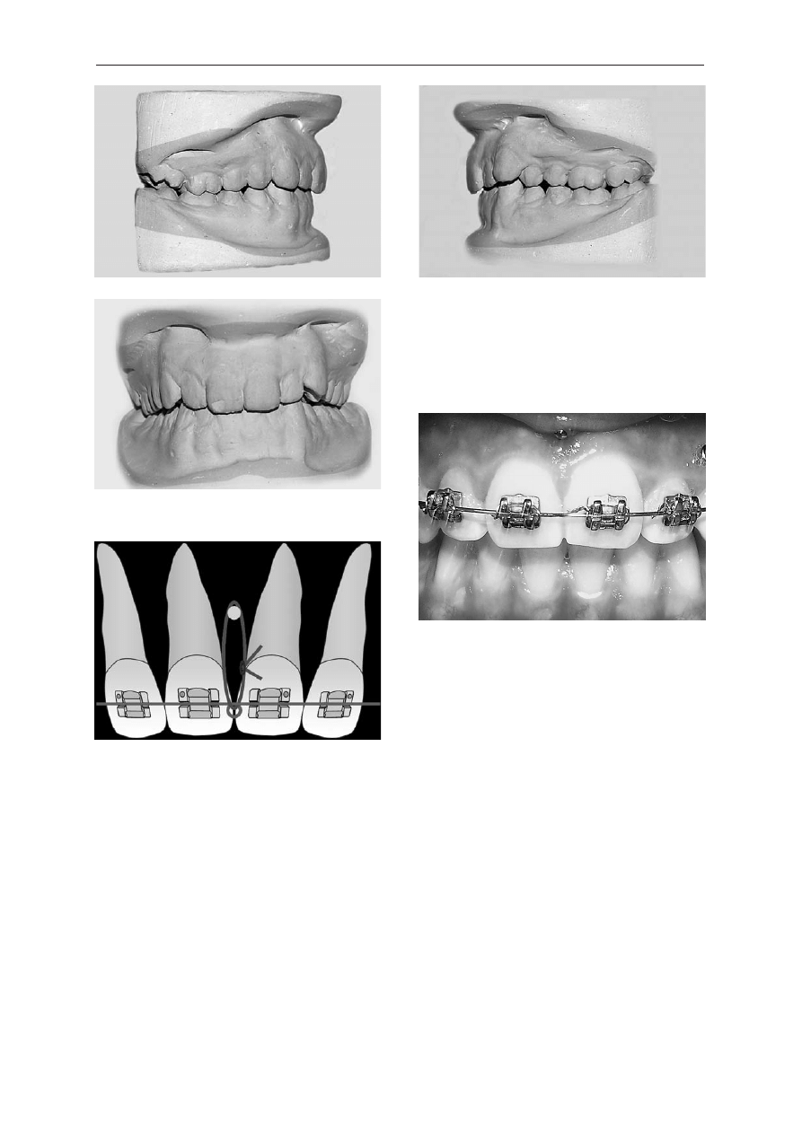
−crossing bases of the nose and the upper lip (Fig. 1).
Intraorally she had an Angle class II (Fig. 2a–b)
and increased overbite (Fig. 2c). Cephalometric
analysis showed no significant abnormalities,
except high value of ANB angle (5.1
o
) – skeletal
component of class II, and retruded upper incisors
(1 + NA = 14
o
). Additional factors, such as young
patient’s age and merely –2 mm of dentoalveolar
discrepancy – all together called for nonextraction
treatment. It started from banding and bonding of
brackets with 0.018 slots in the upper arch; for le−
veling 0.016 round NiTi archwire with minimum
friction was applied (Low Force
®
, Forestadent
®
).
At this stage, a 7−mm−long microscrew – 1.2 dia−
meter – was placed between central incisors, under
the nasal spine, in medium position: 7 mm above
the archwire plane. Subsequently, upper incisors
were intruded with a force of 50 G generated by
a rectangular elastic thread (Superthread
®
, Den−
tos
®
), extending from the microimplant to the ma−
in archwire (Fig. 3). After 8 weeks bite−opening
was visible (Fig. 4), then lower round (0.016) Low
Force
®
was inserted in 0.018 slots of brackets.
0.016
×
0.022 Low Force
®
and 0.018 stainless ste-
el archwires respectively replaced the initial ones.
The next phase required implantation of two coni-
cal, 8-mm-long microscrews – 1.2 diameter – into
the vestibular, cortical bone, between roots of
upper second premolar and first molar, on either
sides. All hitherto used microimplants were trea-
ted as self-tapping ones: vertical 4-mm-long inci-
sion of oral mucosa and preparation of an oblique
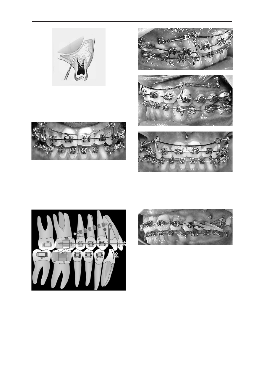
canal with a pilot-drill (Fig. 5) preceded screw
tightening. Anatomy of the buccal alveolar surface
compelled vertical positioning of microimplants in
the borderline between low and high position –
5 mm above the archwire level. Consequently, the
distalizing force passing beneath the center of re-
sistance of the frontal teeth could have possibly in-
tensified initial retrusion of upper incisors. Such
undesired phenomena was prevented by extra
elongated hooks bent on the basic, 0.016
×
0.022
stainless steel archwire. Nevertheless, hooks 10-mm
-long displayed high tendency to bend distally,
therefore – in order to keep them upright – a stabi-
lizing, passive sectional archwire was utilized
(Fig. 6).
Lateral microimplants were loaded after 2 weeks
of soft tissue healing; 8−mm−long closed coil−
springs were stretched between screws and hooks
thus generating 180 G of distalizing force. Special
tiny holes in eye−lets of coil−springs (manufactu−
red by Dentos
®
) enabled tightening them firmly to
microscrews (Fig. 7). Six months later, molar and
canine class I relationships on both sides were re−
established (Fig. 8a–b), upper and lower midlines
coincided (Fig. 8c).
During finishing, for occlusion settling with−
out any side−effects on first lower molars, two mi−
J. A
NTOSZEWSKA
276
Fig. 1. Facial profile before treatment
Ryc. 1. Profil twarzy przed leczeniem
croscrews were implanted buccaly between roots
of first and second molars, on either sides of the
mandible. Implantation technique, suitable for
self−tapping screws, resembled one applied in the
maxilla. Two weeks later, microimplants were
loaded with 150 G of force per side, generated by
¼ medium elastics (Fig. 9) displacing whole man-
dible forward; finishing phase is still in progress.
Discussion
Conventional consecutive distal movement of
teeth, despite of its effectiveness, still brings a cer−
tain amount of anterior anchorage loss – mesial
movement of premolars contributes 20 to 40% of
the space created during distalization of molars;
furthermore distal tipping of the latter ones (rang−
ing from 4 to 14
o
) also becomes evident in routine
biomechanics [12, 13]. Intra−arch devices, such as
Keles Slider with NiTi coil−spring [14] or lingual
NiTi coil [15] successfully overcame the problem
of molar tipping, nevertheless both still provided
movement of single teeth against the device rather
than simultaneous retraction of the whole denti−
tion.
Search for stationary absolute anchorage have
demonstrated that implants utilized in prosthetics
were also applicable for orthodontic purposes. Pa−
latal implants supporting modified Distal Jet [16]
Class II Division 2 Treatment by Absolute Anchorage
277
Fig. 2. Dental casts before treatment:
a – right side, b – left side, c – en face
Ryc. 2. Modele przed leczeniem: a – strona prawa,
b – strona lewa, c – z przodu
Fig. 3. Scheme of Superthread
®
(0>) attached to main
archwire and passing through the hole in the head of
screw (
z
), thus loading the microimplant
Ryc. 3. Schemat nici Superthread
®
(0>) dowiązanej do
łuku podstawowego i przechodzącej przez otwór
w główce śruby (
z
), obciążającej w ten sposób mikro−
implant
Fig. 4. Treatment progress: apparent overbite decrease
Ryc. 4. Postęp leczenia: widoczne spłycenie nagryzu
pionowego
a
b
c
or Pendulum appliances [17], turned out to be re−
sistant against 250 G of distalizing force absolute−
ly adequate to provide en masse retraction. How−
ever, high cost, limited number of implantation
areas and necessity of delayed loading result in
cortical screws privilege over endosseous choice.
Sliding mechanics with the aid of the micro−
screw implant anchorage (MIA) and its applica−
tion for nonextraction treatment has not been wi−
dely discussed, although since screws have been
J. A
NTOSZEWSKA
278
Fig. 5. Scheme of pilot drilling and angulation
of the canal for microscrew−implant
Ryc. 5. Schemat prowadzenia wiertła pilotowego i na−
chylenia kanału dla mikrośruby
Fig. 6. Segmented archwire keeping hooks upright.
Noticeable symptoms of improper oral hygiene requi−
red professional re−training and plaque removal
Ryc. 6. Łuk odcinkowy pionizujący haczyki. Wyraźne
symptomy niewłaściwej higieny wymagały ponowne−
go profesjonalnego instruktażu i usunięcia złogów na−
zębnych
Fig. 7. Scheme of biomechanics applied for class II/2
treatment. Symbols:
®
– center of resistance,
z
– head of microimplants,
– closed coil spring,
}
– eyelet. Line displays archwire with the
customized hook
Ryc. 7. Schemat biomechaniki zastosowanej w lecze−
niu klasy II/2. Oznaczenia:
®
– centrum oporu,
z
– główka mikroimplantu,
– zwój sprężyny
zamkniętej,
}
– zaczep oczkowy. Linia oznacza łuk
podstawowy z indywidualnie dogiętym haczykiem
Fig. 8. Intraoral pictures after 12 months of treatment:
a – right side, b – left side, c – en face
Ryc. 8. Zdjęcia wewnątrzustne po 12 miesiącach
leczenia: a – strona prawa, b – strona lewa,
c – z przodu
Fig. 9. Class II elastics stretched between lower mi−
croscrew and hook of the canine−bracket, stabilizing
reestablished class I
Ryc. 9. Wyciągi klasy II rozpięte między dolną mikro−
śrubą i haczykiem zamka na kle, stabilizujące odtwo−
rzoną klasę I
a
b
c

introduced in clinical orthodontics [18] these pre−
sented the clinician with a versatile option. The
use of microscrews in the case reported enabled en
masse retraction of teeth, without any reciprocal
effect on the anchored unit; screws remained sta−
ble and did not show any mobility throughout the
treatment. Choice of self−tapping method of im−
plantation could have possibly been crucial for
firm fixation of screws: incision of gingiva and pi−
lot drilling prohibited either dragging of soft tissue
into screw−canal or excessive pressure during
screw tightening. By placing microscrew implants
at 30–40
o
to the long axes of the crowns, the api−
ces of the microscrew implants were kept apart
from the roots. Therefore, the possibility of dama−
ge to the roots was eliminated as well as a chance
that the roots of the teeth might have touched mi−
croscrew implants during retraction. The occlusal−
−gingival height of the microimplants and position
of the customized hooks together determined the
direction of the line of force relative to the center
of resistance, thus permitting predictable biome−
chanical control of the movements. The contact on
the crowns of teeth acted as a resistance to move−
ment, which created a counterclockwise moment
on the anterior teeth, resulting in their distal dis−
placement and proclination favorable in class II di−
vision 2 treatment.
Park [19] proved that ability to produce abso−
lute anchorage against which posterior teeth could
be retracted as a unit shorten treatment time due to
group movement of teeth, not to rapid tooth move−
ment possibly increasing risk of root resorption. It
was also true in the presented case were en masse
retraction of the whole dentition was achieved
after 6 months. Relation of microscrew to the
crown of the second premolar (Fig. 8a) displayed
efficiency and range of distal movement of the
upper teeth. Buccal crown torque and buccal fla−
ring bend prevented against undesired lingual tip−
ping and distal rotation reported in the literature
[20] as the side effects of a distalizing force ap−
plied on the vestibular side.
The author conclude that efficient distal move−
ment of upper molars is difficult to achieve co−
nventionally, since routine biomechanics enforces
either adverse anchorage loss or uncontrolled mo−
lar rotation and tipping. Furthermore, there is no
possibility to obtain dental unit withstanding si−
multaneous retraction of all teeth, so class II divi−
sion 2 treatment requires several, time−consuming
phases of distalization.
Ability to provide absolute anchorage for the
en masse distal bodily movement not only counte−
racts undesired movement but shortens the treat−
ment time distinctly, therefore nonextraction treat−
ment supported by the microscrew implants is be−
neficial for both clinicians and patients.
Class II Division 2 Treatment by Absolute Anchorage
279
References
[1] W
ONG
R.W.K.: Combined orthodontic–dentofacial orthopedic treatment of a Class II division 2 patient with seve−
re deep bite. J. Orthod. 2002, 29, 181–188.
[2] S
ELWYN
−B
ARNETT
B.J.: Rationale of treatment for Class II division 2 malocclusion. Br. J. Orthod. 1991, 18,
173–181.
[3] G
ULATI
S., K
HARBANDA
O.P., P
ARKASH
H.: Dental and skeletal changes after intraoral molar distalization with sec−
tional jig assembly. Am. J. Orthod. Dentofac. Orthop. 1998, 114, 319–327.
[4] T
ANER
T.U., Y
UKAY
F., P
EHLIVANOGLU
M., C
AKIRER
B.: Comparative analysis of maxillary tooth movement pro−
duced by cervical headgear and Pend−X appliance. Angle Orthod. 2003, 73, 686–691.
[5] M
ATTHEWS
−B
RZOZOWSKA
T., K
AWALA
B., A
NTOSZEWSKA
J., G
OLUSIK
K.: Porównanie skuteczności dystalizacyjnej
wyciągu zewnątrzustnego oraz przerzutu podniebiennego. Dent. Med. Probl. 2003, 40, 373–376.
[6] P
AUL
L.D., O’B
RIEN
K.D., M
ANDALL
N.A.: Upper removable appliance or Jones Jig for distalizing first molars?
A randomized clinical trial. Orthod. Craniofac. Res. 2002, 5, 238–242.
[7] M
USE
D.S., F
ILLMAN
M.J., E
MMERSON
W.J., M
ITCHEL
R.D.: Molar and incisors changes with Wilson rapid molar
distalization. Am. J. Orthod. Dentofac. Orthop. 1993, 104, 556–565.
[8] M
ATTHEWS
−B
RZOZOWSKA
T., A
NDRYCH
M.: Leczenie ortodontyczne aparatem MALU wad klasy II. Twój Prz.
Stomat. 2005, 5, 47–50.
[9] B
IELACZYC
A.: Zmiany w położeniu zębów po leczeniu aparatem Herbsta na szynach akrylowych u pacjentów
z tyłożuchwiem czynnościowym i zgryzem głębokim. Czas. Stomat. 2002, 55, 250–259.
[10] P
ARK
H.S.: Do miniscrews remain stationary under orthodontic forces? Korea J. Orthod. 2002, 32, 435–441.
[11] S
UNG
J.H., K
YUNG
H.M., B
AE
S.M., P
ARK
H.S., K
WON
O.W., M
C
N
AMARA
J.A.: Biomechanical considerations in
microimplant anchorage. In: Microimplants in Orthodontics. Eds.: Sung J.H., Kyung H.M., Bae S.M., Park H.S.,
Kwon O.W., McNamara J.A., Dentos, Daegu 2006, 63–81.
[12] B
OLLA
E., M
URATORE
F., C
ARANO
A., B
OWMAN
S.J.: Evaluation of maxillary molar distalization with the distal jet:
a comparison with other contemporary methods. Angle Orthod. 2002, 72, 481–494.
[13] B
YLOFF
F.K., D
ARENDELILER
M.A.: Distal molar movement using pendulum appliance. Part 1: clinical and radio−
logical evaluation. Angle Orthod. 1997, 67, 249–260.
[14] K
ELES
A.: Maxillary unilateral molar distalization with sliding mechanics: a preliminary investigation. Eur. J.
Orthod. 2001, 23, 507–515.

[15] B
ONDEMARK
L.: A comparative analysis of distal maxillary molar movement produced by a new lingual intra−arch
Ni−Ti coil appliance and a magnetic appliance. Eur. J. Orthod. 2000, 22, 683–695.
[16] K
ARCHER
H., B
YLOFF
F.K., C
LAR
E.: The Graz implant supported pendulum, a technical note. J. Cranio−Maxillo−
fac Surg. 2002, 30, 87–90.
[17] K
ARAMAN
A.I., B
ASCIFTCI
F.A., P
OLAT
O.: Unilateral distal molar movement with an implant−supported distal jet
appliance. Angle Orthod. 2002, 72, 167–174.
[18] C
REEKMORE
T.D., E
KLUND
M.K.: The possibility of skeletal anchorage. J. Clin. Orthod. 1983, 17, 266–269.
[19] P
ARK
H.S.: The skeletal cortical anchorage using titanium microscrew implants. Korea J. Orthod. 1992, 29,
699–705.
[20] P
ARK
H.M., K
WON
T.G., S
UNG
J.H.: Nonextraction treatment with microscrew implants. Angle Orthod. 2004, 74,
539–549.
Address for correspondence:
Joanna Antoszewska
Department of Dentofacial Orthopedics and Orthodontics
Silesian Piasts University of Medicine
Krakowska 26
50−425 Wrocław
Poland
Tel.: +48 71 784 02 99
E−mail: joanna.antoszewska@stomatologia.com
Received: 10.01.2007
Revised: 26.03.2007
Accepted: 31.05.2007
Praca wpłynęła do Redakcji: 10.01.2007 r.
Po recenzji: 26.03.2007 r.
Zaakceptowano do druku: 31.05.2007 r.
J. A
NTOSZEWSKA
280
Wyszukiwarka
Podobne podstrony:
17.09.08-Scenariusz zajęć dla klasy II-Dodawanie i odejmowanie do 20, Konspekty
PRZYKŁADOWE TEKSTY PISANIA Z PAMIĘCI DLA KLASY II
Elektroinstalator 2009 06 koordynacja ochronników klasy I [B] i II [C]
plan wynikowy dla klasy II
scenariusz lekcji klasy II kwiaty, KLASY I - III, Scenariusze kl. - III
Sprawdzian z edukacji polonistycznej dla klasy II, szkoła, j,polski, sprawdziany
23.09.08-Scenariusz zajęć dla klasy II-Podziwiamy ogrody kwiatowe, Konspekty
Konspekt zajęć zintegrowanych dla klasy II 23.03, Scenariusze i konspekty
LECZENIE CUKRZYCY II
SPRAWDZIAN DLA KLASY II dodawanie i odejmowanie w zakresie , październik
TEST DLA KLASY II LICEUM
ROZKŁAD MATERIAŁU DLA KLASY II GIMNAZJUM ZAJ INDYWID 11 12
PROGRAM Zajęc z muzyki dla klasy II, pliki zamawiane, edukacja
Bawimy się w lustra – na podstawie „Lustereczka” D Gellner (konspekt zajęć dramowych dla klasy II)
5256, Scenariusz zajęć z edukacji środowiskowo-polonistycznej dla klasy II
Regulamin klasy II c
więcej podobnych podstron