Steel Design Guide Series
Steel and Composite Beams with
Web Openings
Steel Design Guide Series
Steel and
Composite Beams
with Web Openings
Design of Steel and Composite Beams with Web Openings
David Darwin
Professor of Civil Engineering
University of Kansas
Lawrence, Kansas
A M E R I C A N
I N S T I T U T E O F S T E E L
C O N S T R U C T I O N
© 2003 by American Institute of Steel Construction, Inc. All rights reserved.
This publication or any part thereof must not be reproduced in any form without permission of the publisher.

Copyright
1990
by
American Institute of Steel Construction, Inc.
All rights reserved. This book or any part thereof
must not be reproduced in any form without the
written permission of the publisher.
The information presented in this publication has been prepared in accordance with rec-
ognized engineering principles and is for general information only. While it is believed
to be accurate, this information should not be used or relied upon for any specific appli-
cation without competent professional examination and verification of its accuracy,
suitablility, and applicability by a licensed professional engineer, designer, or architect.
The publication of the material contained herein is not intended as a representation
or warranty on the part of the American Institute of Steel Construction or of any other
person named herein, that this information is suitable for any general or particular use
or of freedom from infringement of any patent or patents. Anyone making use of this
information assumes all liability arising from such use.
Caution must be exercised when relying upon other specifications and codes developed
by other bodies and incorporated by reference herein since such material may be mod-
ified or amended from time to time subsequent to the printing of this edition. The
Institute bears no responsibility for such material other than to refer to it and incorporate
it by reference at the time of the initial publication of this edition.
Printed in the United States of America
Second Printing: September 1991
Third Printing: October 2003
© 2003 by American Institute of Steel Construction, Inc. All rights reserved.
This publication or any part thereof must not be reproduced in any form without permission of the publisher.

TABLE OF CONTENTS
INTRODUCTION . . . . . . . . . . . . . . . . . . . . . . . . . . . . .
1
DEFINITIONS AND NOTATION . . . . . . . . . . . . . . . 3
2.1 Definitions . . . . . . . . . . . . . . . . . . . . . . . . . . . . . . . 3
2.2 N o t a t i o n . . . . . . . . . . . . . . . . . . . . . . . . . . . . . . . . . 3
DESIGN OF MEMBERS WITH WEB OPENINGS 7
3.1 G e n e r a l . . . . . . . . . . . . . . . . . . . . . . . . . . . . . . . . . . 7
3.2 Load and Resistance Factors . . . . . . . . . . . . . . . . 7
3.3 Overview of Design Procedures . . . . . . . . . . . . . 7
3.4 Moment-Shear Interaction . . . . . . . . . . . . . . . . . . 8
3.5 Equations for Maximum Moment Capacity,
M
m
. . . . . . . . . . . . . . . . . . . . . . . . . . . . . . . . . . . . . 8
3.6 Equations for Maximum Shear Capacity, V
m
. . . 10
3.7 Guidelines for Proportioning and Detailing
Beams with Web O p e n i n g s . . . . . . . . . . . . . . . . . . 12
3.8 Allowable Stress Design . . . . . . . . . . . . . . . . . . . . 16
DESIGN SUMMARIES AND EXAMPLE
P R O B L E M S . . . . . . . . . . . . . . . . . . . . . . . . . . . . . . . . . 17
4.1 General.. . . . . . . . . . . . . . . . . . . . . . . . . . . . . . . . . 17
4.2 Example 1: Steel Beam with Unreinforced
Opening . . . . . . . . . . . . . . . . . . . . . . . . . . . . . . . . . 22
4.3 Example 1A: Steel Beam with Unreinforced
Opening—ASD Approach . . . . . . . . . . . . . . . . . . 23
4.4 Example 2: Steel Beam with Reinforced
O p e n i n g . . . . . . . . . . . . . . . . . . . . . . . . . . . . . . . . . 24
4.5 Example 3: Composite Beam with
Unreinforced Opening . . . . . . . . . . . . . . . . . . . . . 27
4.6 Example 4: Composite Girder with
Unreinforced and Reinforced Openings . . . . . . . . 30
BACKGROUND AND COMMENTARY . . . . . . . . . . 37
5.1 G e n e r a l . . . . . . . . . . . . . . . . . . . . . . . . . . . . . . . . . . 37
5.2 Behavior of Members with Web Openings . . . . . 37
5.3 Design of Members with Web Openings . . . . . . 40
5.4 Moment-Shear Interaction . . . . . . . . . . . . . . . . . . 41
5.5 Equations for Maximum Moment Capacity . . . . 42
5.6 Equations for Maximum Shear Capacity . . . . . . 44
5.7 Guidelines for Proportioning and Detailing
Beams with Web Openings . . . . . . . . . . . . . . . . . 48
5.8 Allowable Stress Design . . . . . . . . . . . . . . . . . . . . 50
D E F L E C T I O N S . . . . . . . . . . . . . . . . . . . . . . . . . . . . . . 51
6.1 General. . . . . . . . . . . . . . . . . . . . . . . . . . . . . . . . . . 51
6.2 Design Approaches . . . . . . . . . . . . . . . . . . . . . . . . 51
6.3 Approximate Procedure . . . . . . . . . . . . . . . . . . . . . 51
6.4 Improved Procedure . . . . . . . . . . . . . . . . . . . . . . . 52
6.5 Matrix A n a l y s i s . . . . . . . . . . . . . . . . . . . . . . . . . . . 53
R E F E R E N C E S . . . . . . . . . . . . . . . . . . . . . . . . . . . . . . . . 55
ADDITIONAL BIBLIOGRAPHY . . . . . . . . . . . . . . . 57
APPENDIX A . . . . . . . . . . . . . . . . . . . . . . . . . . . . . . . . 59
INDEX . . . . . . . . . . . . . . . . . . . . . . . . . . . . . . . . . . . . . . 63
© 2003 by American Institute of Steel Construction, Inc. All rights reserved.
This publication or any part thereof must not be reproduced in any form without permission of the publisher.

PREFACE
This booklet was prepared under the direction of the Com-
mittee on Research of the American Institute of Steel Con-
struction, Inc. as part of a series of publications on special
topics related to fabricated structural steel. Its purpose is to
serve as a supplemental reference to the AISC Manual of
Steel Construction to assist practicing engineers engaged in
building design.
The design guidelines suggested by the author that are out-
side the scope of the AISC Specifications or Code do not
represent an official position of the Institute and are not in-
tended to exclude other design methods and procedures. It
is recognized that the design of structures is within the scope
of expertise of a competent licensed structural engineer, ar-
chitect or other licensed professional for the application of
principles to a particular structure.
The sponsorship of this publication by the American Iron
and Steel Institute is gratefully acknowledged.
The information presented in this publication has been prepared in accordance with recognized engineer-
ing principles and is for general information only. While it is believed to be accurate, this information should
not be used or relied upon for any specific application without competent professional examination and verifi-
cation of its accuracy, suitability, and applicability by a licensed professional engineer, designer or archi-
tect. The publication of the material contained herein is not intended as a representation or warranty on
the part of the American Institute of Steel Construction, Inc. or the American Iron and Steel Institute, or
of any other person named herein, that this information is suitable for any general or particular use or of
freedom infringement of any patent or patents. Anyone making use of this information assumes all liability
arising from such use.
© 2003 by American Institute of Steel Construction, Inc. All rights reserved.
This publication or any part thereof must not be reproduced in any form without permission of the publisher.

Chapter 1
INTRODUCTION
Height limitations are often imposed on multistory buildings
based on zoning regulations, economic requirements and es-
thetic considerations, including the need to match the floor
heights of existing buildings. The ability to meet these restric-
tions is an important consideration in the selection of a fram-
ing system and is especially important when the framing sys-
tem is structural steel. Web openings can be used to pass
utilities through beams and, thus, help minimize story height.
A decrease in building height reduces both the exterior sur-
face and the interior volume of a building, which lowers oper-
ational and maintenance costs, as well as construction costs.
On the negative side, web openings can significantly reduce
the shear and bending capacity of steel or composite beams.
Web openings have been used for many years in structural
steel beams, predating the development of straightforward
design procedures, because of necessity and/or economic ad-
vantage. Openings were often reinforced, and composite
beams were often treated as noncomposite members at web
openings. Reinforcement schemes included the use of both
horizontal and vertical bars, or bars completely around the
periphery of the opening. As design procedures were devel-
oped, unreinforced and reinforced openings were often ap-
proached as distinct problems, as were composite and non-
composite members.
In recent years, a great deal of progress has been made
in the design of both steel and composite beams with web
openings. Much of the work is summarized in state-of-the-
art reports (Darwin 1985, 1988 & Redwood 1983). Among
the benefits of this progress has been the realization that the
behavior of steel and composite beams is quite similar at
web openings. It has also become clear that a single design
approach can be used for both unreinforced and reinforced
openings. If reinforcement is needed, horizontal bars above
and below the opening are fully effective. Vertical bars or
bars around the opening periphery are neither needed nor
cost effective.
This guide presents a unified approach to the design of
structural steel members with web openings. The approach
is based on strength criteria rather than allowable stresses,
because at working loads, locally high stresses around web
openings have little connection with a member's deflection
or strength.
The procedures presented in the following chapters are for-
mulated to provide safe, economical designs in terms of both
the completed structure and the designer's time. The design
expressions are applicable to members with individual open-
ings or multiple openings spaced far enough apart so that
the openings do not interact. Castellated beams are not in-
cluded. For practical reasons, opening depth is limited to
70 percent of member depth. Steel yield strength is limited
to 65 ksi and sections must meet the AISC requirements for
compact sections (AISC 1986).
1
© 2003 by American Institute of Steel Construction, Inc. All rights reserved.
This publication or any part thereof must not be reproduced in any form without permission of the publisher.
Chapter 2
DEFINITIONS AND NOTATION
2.1 DEFINITIONS
The following terms apply to members with web openings.
bottom tee—region of a beam below an opening.
bridging—separation of the concrete slab from the steel sec-
tion in composite beams. The separation occurs over an
opening between the low moment end of the opening and
a point outside the opening past the high moment end of
the opening.
high moment end—the edge of an opening subjected to the
greater primary bending moment. The secondary and pri-
mary bending moments act in the same direction.
low moment end—the edge of an opening subjected to the
lower primary bending moment. The secondary and pri-
mary bending moments act in opposite directions.
opening parameter—quantity used to limit opening size and
aspect ratio.
plastic neutral axis—position in steel section, or top or bot-
tom tees, at which the stress changes abruptly from ten-
sion to compression.
primary bending moment—bending moment at any point
in a beam caused by external loading.
reinforcement—longitudinal steel bars welded above and be-
low an opening to increase section capacity.
reinforcement, slab—reinforcing steel within a concrete slab.
secondary bending moment—bending moment within a tee
that is induced by the shear carried by the tee.
tee—region of a beam above or below an opening.
top tee—region of a beam above an opening.
unperforated member—section without an opening. Refers
to properties of the member at the position of the opening.
Gross transformed area of a tee
Area of flange
Cross-sectional area of reinforcement along
top or bottom edge of opening
Cross-sectional area of steel in unperforated
member
Cross-sectional area of shear stud
Net area of steel section with opening and
reinforcement
Net steel area of top tee
Area of a steel tee
Effective concrete shear area =
Effective shear area of a steel tee
Diameter of circular opening
Modulus of elasticity of steel
Modulus of elasticity of concrete
Horizontal forces at ends of a beam element
Yield strength of steel
Reduced axial yield strength of steel; see
Eqs. 5-19 and 5-20
Vertical forces at ends of a beam element
Yield strength of opening reinforcement
Shear modulus =
Moment of inertia of a steel tee, with
subscript b or t
Moment of inertia of bottom steel tee
Moment of inertia of unperforated steel
beam or effective moment of inertia of
unperforated composite beam
Moment of inertia of perforated beam
Moment of inertia of tee
Moment inertia of top steel tee
Torsional constant
Shape factor for shear
Elements of beam stiffness matrix, i, j = 1, 6
Stiffness matrix of a beam element
Length of a beam
Unbraced length of compression flange
Bending moment at center line of opening
Secondary bending moment at high and low
moment ends of bottom tee, respectively.
Maximum nominal bending capacity at the
location of an opening
Nominal bending capacity
Plastic bending capacity of an unperforated
steel beam
Plastic bending capacity of an unperforated
composite beam
Secondary bending moment at high and low
moment ends of top tee, respectively
Factored bending moment
Moments at ends of a beam element
Number of shear connectors between the
high moment end of an opening and the
support
Number of shear connectors over an
opening
Axial force in top or bottom tee
Force vector for a beam element
Axial force in bottom tee
Axial force in concrete for a section under
pure bending
2.2 NOTATION
3
© 2003 by American Institute of Steel Construction, Inc. All rights reserved.
This publication or any part thereof must not be reproduced in any form without permission of the publisher.
Minimum value of
for which Eq. 3-10 is
accurate =
Axial force in concrete at high and low
moment ends of opening, respectively, for a
section at maximum shear capacity
Plastic neutral axis
Axial force in opening reinforcement
Axial force in top tee
Individual shear connector capacity, includ-
ing reduction factor for ribbed slabs
Ratio of factored load to design capacity at
an opening =
Strength reduction factor for shear studs in
ribbed slabs
Required strength of a weld
Clear space between openings
Tensile force in net steel section
Displacement vector for a beam element
Shear at opening
Shear in bottom tee
Calculated shear carried by concrete slab =
which-
ever is less
Maximum nominal shear capacity at the
location of an opening
Maximum nominal shear capacity of bottom
and top tees, respectively
Pure shear capacity of top tee
Nominal shear capacity
Plastic shear capacity of top or bottom tee
Plastic shear capacity of unperforated beam
Plastic shear capacity of bottom and top
tees, respectively
Shear in top tee
Factored shear
Plastic section modulus
Length of opening
Depth of concrete compressive block
Projecting width of flange or reinforcement
Effective width of concrete slab
Sum of minimum rib widths for ribs that lie
within for
composite beams with longitu-
dinal ribs in slab
Width of flange
Depth of steel section
Distance from top of steel section to cen-
troid of concrete force at high and low
moment ends of opening, respectively.
Distance from outside edge of flange to cen-
troid of opening reinforcement; may have
different values in top and bottom tees
Eccentricity of opening; always positive for steel
sections; positive up for composite sections
Compressive (cylinder) strength of concrete
Depth of opening
Distance from center of gravity of unper-
forated beam to center of gravity of a tee
section, bottom tee, and top tee, respectively.
Length of extension of reinforcement beyond
edge of opening
Distance from high moment end of opening
to adjacent support
Distance from low moment end of opening
to adjacent support
Distance from support to point at which
deflection is calculated
Distance from high moment end of opening
to point at which deflection is calculated
Opening parameter =
Ratio of midspan deflection of a beam with
an opening to midspan deflection of a beam
without an opening
Depth of a tee, bottom tee and top tee,
respectively
Effective depth of a tee, bottom tee and top
tee, respectively, to account for movement
of PNA when an opening is reinforced; used
only for calculation of
Thickness of flange or reinforcement
Effective thickness of concrete slab
Thickness of flange
Total thickness of concrete slab
Thickness of concrete slab above the rib
Thickness of web
Horizontal displacements at ends of a beam
element
Vertical displacements at ends of a beam
element
Uniform load
Factored uniform load
Distance from top of flange to plastic neu-
tral axis in flange or web of a composite
beam
Distance between points about which sec-
ondary bending moments are calculated
Variables used to calculate
Ratio of maximum nominal shear capacity
to plastic shear capacity of a tee,
Term in stiffness matrix for equivalent beam
element at web opening; see Eq. 6-12
Net reduction in area of steel section due to
presence of an opening and reinforcement =
4
© 2003 by American Institute of Steel Construction, Inc. All rights reserved.
This publication or any part thereof must not be reproduced in any form without permission of the publisher.
Dimensionless ratio relating the secondary
bending moment contributions of concrete
and opening reinforcement to the product of
the plastic shear capacity of a tee and the
depth of the tee
Ratio of length to depth or length to effec-
tive depth for a tee, bottom tee or top tee,
respectively =
Poisson's ratio
Average shear stress
Resistance factor
Bottom tee
Maximum or mean
Nominal
Top tee
Factored
Maximum deflection due to bending of a
beam without an opening
Maximum deflection of a beam with an
opening due to bending and shear
Deflection through an opening
Bending deflection through an opening
Shear deflection through an opening
Components of deflection caused by pres-
ence of an opening at a point between high
moment end of opening and support
Maximum deflection due to shear of a beam
without an opening
Rotations of a beam at supports due to pres-
ence of an opening =
see Eq.
6-12
Rotations used to calculate beam deflections
due to presence of an opening; see Eq. 6-3
Rotations at ends of a beam element
Constant used in linear approximation of
von Mises yield criterion; recommended
value
5
© 2003 by American Institute of Steel Construction, Inc. All rights reserved.
This publication or any part thereof must not be reproduced in any form without permission of the publisher.
Chapter 3
DESIGN OF MEMBERS WITH WEB OPENINGS
3.1 GENERAL
This chapter presents procedures to determine the strength
of steel and composite beams with web openings. Compos-
ite members may have solid or ribbed slabs, and ribs may
be parallel or perpendicular to the steel section. Openings
may be reinforced or unreinforced. Fig. 3.1 illustrates the
range of beam and opening configurations that can be han-
dled using these procedures. The procedures are compatible
with the LRFD procedures of the American Institute of Steel
Construction, as presented in the Load and Resistance Fac-
tor Design Manual of Steel Construction (AISC 1986a). With
minor modifications, the procedures may also be used with
Allowable Stress Design techniques (see section 3.8).
Design equations and design aids (Appendix A) based on
these equations accurately represent member strength with
a minimum of calculation. The derivation of these equations
is explained in Chapter 5.
The design procedures presented in this chapter are limited
to members with a yield strength
65 ksi meeting the
AISC criteria for compact sections (AISC 1986b). Other
limitations on section properties and guidelines for detail-
ing are presented in section 3.7. Design examples are
presented in Chapter 4.
3.2 LOAD
AND RESISTANCE FACTORS
The load factors for structural steel members with web open-
ings correspond to those used in the AISC Load and Resis-
tance Factor Design Specifications for Structural Steel Build-
ings (AISC 1986b).
Resistance factors, 0.90
for
steel members and 0.85
for composite members, should be applied to both moment
and shear capacities at openings.
Members should be proportioned so that the factored
loads are less than the design strengths in both bending and
shear.
3.3 OVERVIEW
OF DESIGN PROCEDURES
Many aspects of the design of steel and composite members
with web openings are similar. At web openings, members
may be subjected to both bending and shear. Under the com-
bined loading, member strength is below the strength that
can be obtained under either bending or shear alone. De-
sign of web openings consists of first determining the maxi-
mum nominal bending and shear capacities at an opening,
and then obtaining the nominal capacities,
and
for the combinations of bending moment and shear
that occur at the opening.
For steel members, the maximum nominal bending
strength, is
expressed in terms of the strength of the
member without an opening. For composite sections, expres-
sions for
are based on the location of the plastic neu-
tral axis in the unperforated member. The maximum nomi-
Fig. 3.1.
Beam and opening configurations, (a) Steel beam
with unreinforced opening, (b) steel beam with
reinforced opening, (c) composite beam, solid slab,
(d) composite beam, ribbed slab with transverse
ribs, (e) composite beam with reinforced opening,
ribbed slab with logitudinal ribs.
in which
M
u
= factored bending moment
V
u
= factored shear
M
n
= nominal flexural strength
V
n
= nominal shear strength
7
© 2003 by American Institute of Steel Construction, Inc. All rights reserved.
This publication or any part thereof must not be reproduced in any form without permission of the publisher.
nal shear capacity, is
expressed as the sum of the shear
capacities, for
the
regions above and below the
opening (the top and bottom tees).
The design expressions for composite beams apply to open-
ings located in positive moment regions. The expressions for
steel beams should be used for openings placed in negative
moment regions of composite members.
The next three sections present the moment-shear inter-
action curve and expressions for
used to design
members with web openings. Guidelines for member propor-
tions follow the presentation of the design equations.
are checked using the interaction curve by plot-
ting the point
If the point lies inside the
R = 1 curve, the opening meets the requirements of Eqs.
3-1 and 3-2, and the design is satisfactory. If the point lies
outside the curve, the design is not satisfactory. A large-scale
version of Fig. 3.2, suitable for design, is presented in Fig.
A.1 of Appendix A.
The value of R at the point
and to
be
obtained
from the applied loads.
3.4 MOMENT-SHEAR INTERACTION
Simultaneous bending and shear occur at most locations
within beams. At a web opening, the two forces interact to
produce lower strengths than are obtained under pure bend-
ing or pure shear alone. Fortunately at web openings, the
interaction between bending and shear is weak, that is, nei-
ther the bending strength nor the shear strength drop off
rapidly when openings are subjected to combined bending
and shear.
The interaction between the design bending and shear
strengths, is
shown
as
the
solid curve in Fig.
3.2 and expressed as
Additional curves are included in Fig. 3.2 with values of R
ranging from 0.6 to 1.2. The factored loads at an opening,
3.5 EQUATIONS
FOR
MAXIMUM
MOMENT CAPACITY,
The equations presented in this section may be used to cal-
culate the maximum moment capacity of steel (Fig 3.3) and
composite (Fig. 3.4) members constructed with compact steel
sections. The equations are presented for rectangular open-
ings. Guidelines are presented in section 3.7 to allow the ex-
pressions to be used for circular openings.
The openings are of length,
height,
and may have
an eccentricity, e, which is measured from the center line
of the steel section. For steel members, e is positive, whether
the opening is above or below the center line. For compos-
ite members, e is positive in the upward direction.
The portion of the section above the opening (the top tee)
has a depth
while the bottom tee has a depth of
If rein-
forcement is used, it takes the form of bars above and below
the opening, welded to one or both sides of the web. The
area of the reinforcement on each side of the opening is
For composite sections, the slab is of total depth,
with
8
© 2003 by American Institute of Steel Construction, Inc. All rights reserved.
This publication or any part thereof must not be reproduced in any form without permission of the publisher.
(b)
Fig. 3.3. Opening
configurations
for
steel
beams, (a)
Unrein-
forced opening, (b) reinforced opening.
b. Composite beams
The expressions for the nominal capacity of a composite
member with a web opening (Fig. 3.4) in pure bend-
ing,
apply to members both with and without
reinforcement.
Plastic neutral axis above top of flange
For beams in which the plastic netural axis, PNA, in the un-
perforated member is located at or above the top of the flange,
Fig. 3.4. Opening
configurations
for
composite
beams.
(a) Unreinforced opening, solid slab,
(b) unreinforced opening, ribbed slab with
transverse ribs, (c) reinforced opening, ribbed
slab with longitudinal ribs.
a minimum depth of
Other dimensions are as shown in
Figs. 3.3 and 3.4.
a. Steel beams
The nominal capacity of a steel member with a web open-
ing in pure bending,
is expressed in terms of the ca-
pacity of the member without an opening,
Unreinforced openings
For members with unreinforced openings,
Reinforced openings
For members with reinforced openings,
depth of opening
thickness of web
eccentricity of opening
plastic section modulus of member without
opening
yield strength of steel
9
© 2003 by American Institute of Steel Construction, Inc. All rights reserved.
This publication or any part thereof must not be reproduced in any form without permission of the publisher.
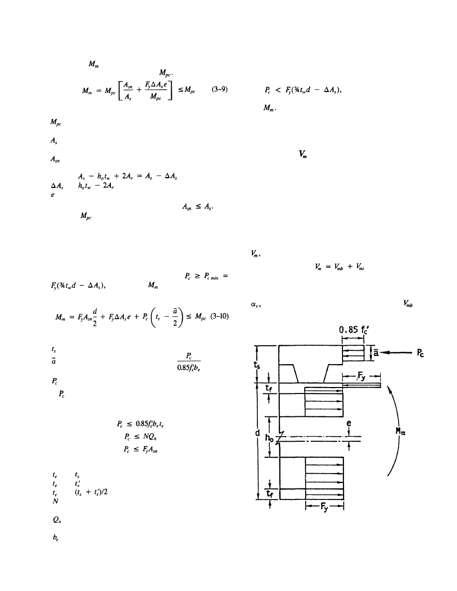
Fig. 3.5. Region at web opening at maximum moment, composite
beam.
10
the value of
may be approximated in terms of the ca-
pacity of the unperforated section,
in which
= nominal capacity of the unperforated composite
section, at the location of the opening
= cross-sectional area of steel in the unperforated
member
= net area of steel section with opening and rein-
forcement
= eccentricity of opening, positive upward
Equation 3-9 is always conservative for
The
values of
can be conveniently obtained from Part 4 of
the AISC Load and Resistance Factor Design Manual (AISC
1986a).
Plastic neutral axis below top of flange
For beams in which the PNA in the unperforated member
is located below the top of the flange and
the value of
may be approximated
using
in which
= thickness of slab
= depth of concrete stress block =
= force in the concrete (Fig. 3.5)
is limited by the concrete capacity, the stud capacity
from the high moment end of the opening to the support,
and the tensile capacity of the net steel section.
(3-11a)
(3-11b)
(3-11c)
in which
= for
solid
slabs
= for
ribbed
slabs with transverse ribs
= for
ribbed
slabs with longitudinal ribs
= number of shear connectors between the high mo-
ment end of the opening and the support
= individual shear connector capacity, including reduc-
tion factor for ribbed slabs (AISC 1986b)
= effective width of concrete slab (AISC 1986b)
Equation 3-10 is also accurate for members with the PNA
in the unperforated section located at or above the top of
the flange.
If the
more accurate expres-
sions given in section 5.5 should be used to calcu-
late
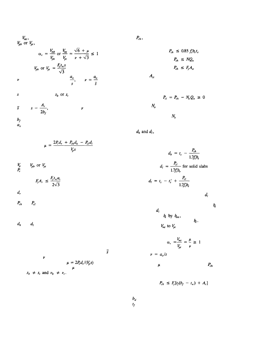
3.6 EQUATIONS
FOR MAXIMUM SHEAR
CAPACITY,
The equations presented in this section may be used to cal-
culate the maximum shear strength of steel and composite
members constructed with compact steel sections. The equa-
tions are presented for rectangular openings and used to de-
velop design aids, which are presented at the end of this sec-
tion and in Appendix A. Guidelines are presented in the next
section to allow the expressions to be used for circular open-
ings. Dimensions are as shown in Figs. 3.3 and 3.4.
The maximum nominal shear capacity at a web opening,
is the sum of the capacities of the bottom and top tees.
(3-12)
a. General equation
the ratio of nominal shear capacity of a tee,
© 2003 by American Institute of Steel Construction, Inc. All rights reserved.
This publication or any part thereof must not be reproduced in any form without permission of the publisher.
11
or
to the plastic shear capacity of the web of the tee,
is calculated as
(3-13)
in which
= aspect ratio of tee =
use
when reinforcement is used
= depth of tee,
= used
to
calculate
when reinforcement is used
= width of flange
= length of opening
Subscripts "b" and "t" indicate the bottom and top tees,
respectively.
(3-14)
in which (see Fig. 3.5)
= force in reinforcement along edge of opening
= distance from outside edge of flange to centroid of
reinforcement
and
= concrete forces at high and low moment ends
of opening, respectively. For top tee in com-
posite sections only. See Eqs. 3-15a through
3-16.
and =
distances
from
outside edge of top flange to
centroid of concrete force at high and low mo-
ment ends of opening, respectively. For top tee
in composite sections only. See Eqs. 3-17
through 3-18b.
For reinforced openings, s should be replaced by in the
calculation of only.
For tees without concrete, .
For
tees with-
out concrete or reinforcement, = 0. For eccentric open-
ings,
Equations 3-13 and 3-14 are sufficient for all types of con-
struction, with the exception of top tees in composite beams
which are covered next.
b. Composite beams
The following expressions apply to the top tee of composite
members. They are used in conjunction with Eqs. 3-13 and 3-4,
the concrete force at the high moment end of the
opening (Eq. 3-14, Fig. 3.6), is
(3-15a)
(3-15b)
(3-15c)
in which
= net steel area of top tee
P
cl
, the concrete force at the low moment end of the
opening (Fig. 3.6), is
(3-16)
in which
= number of shear connectors over the
opening.
N in Eq. 3-15b and
in Eq. 3-16 include only connec-
tors completely within the defined range. For example, studs
on the edges of an opening are not included.
the distances from the top of the flange to the
centroid of the concrete force at the high and the low mo-
ment ends of the opening, respectively, are
(3-17)
(3-18a)
for ribbed slabs (3-18b)
with transverse ribs
For ribbed slabs with longitudinal ribs,
is based on the
centroid of the compressive force in the concrete consider-
ing all ribs that lie within the effective width
(Fig. 3.4).
In this case, can
be
conservatively
obtained using Eq.
3-18a, replacing the
sum
of
the
minimum rib
widths for the ribs that lie within
If the ratio of
in Eq. 3-13 exceeds 1, then an al-
ternate expression must be used.
(3-19)
in which
for both reinforced and unreinforced
openings.
To evaluate
in Eq. 3-19, the value of
in Eq. 3-15
must be compared with the tensile force in the flange and
reinforcement, since the web has fully yielded in shear.
(3-20)
in which
= width of flange
= thickness of flange
Equation 3-20 takes the place of Eq. 3-15c.
© 2003 by American Institute of Steel Construction, Inc. All rights reserved.
This publication or any part thereof must not be reproduced in any form without permission of the publisher.
If Eq. 3-20 governs instead
of
Eq.
3-15,
and must
also be recalculated using Eqs. 3-16, 3-17, 3-18,
and 3-14, respectively.
Finally,
must not be greater than the pure shear ca-
pacity of the top tee,
(3-21)
in which
are in ksi
= effective concrete shear area
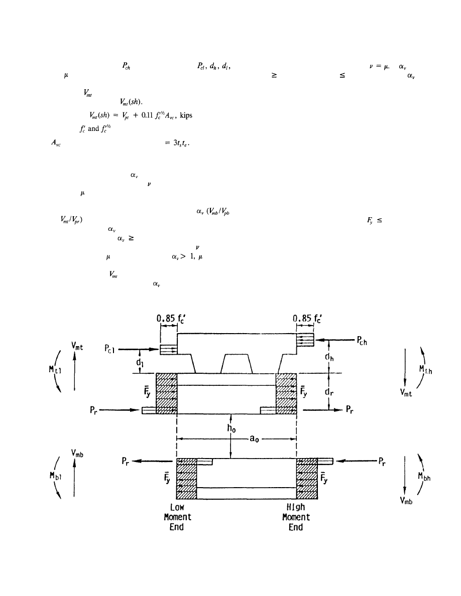
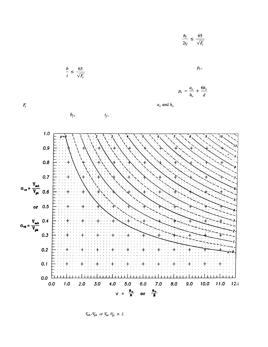
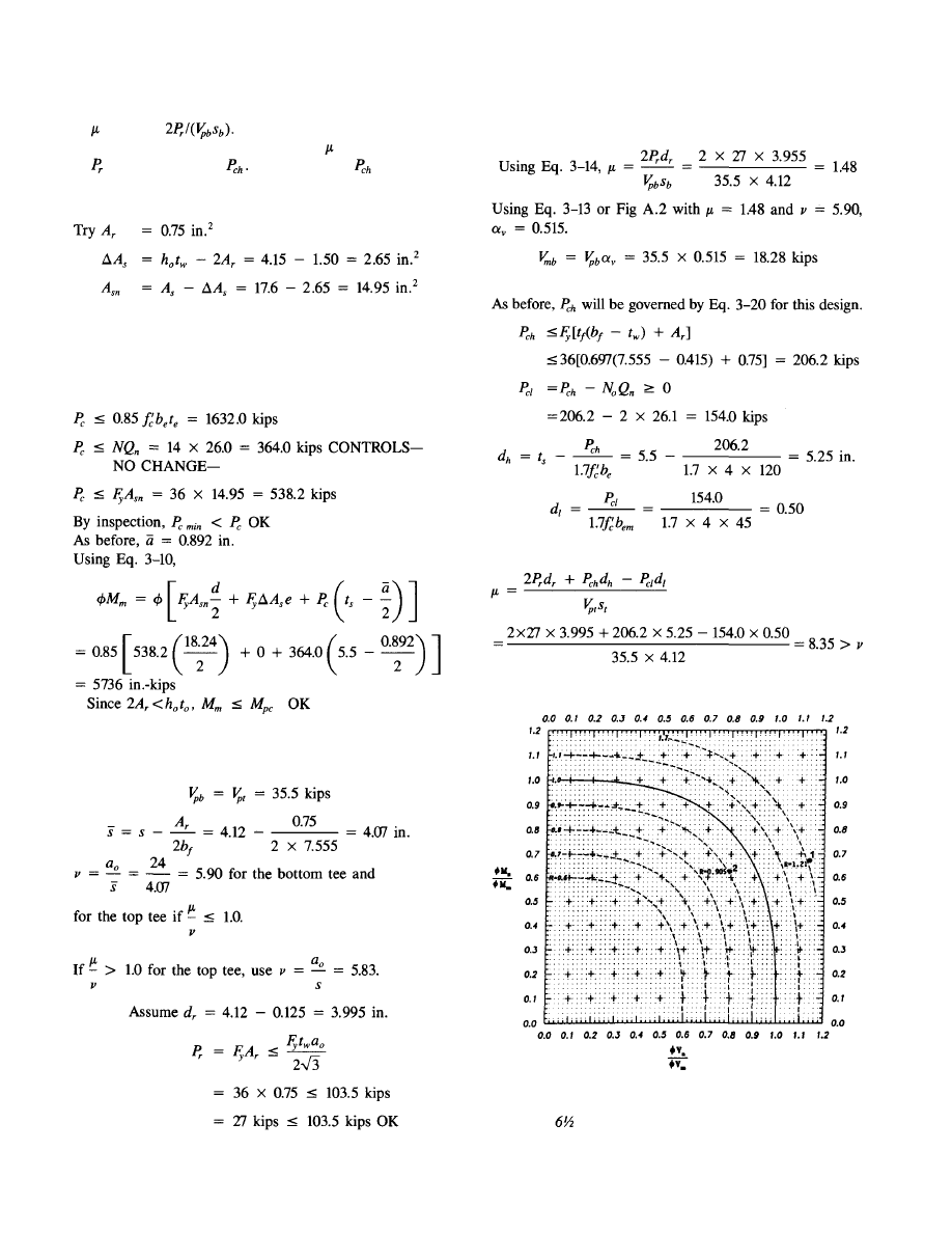
c. Design aids
A design aid representing from
Eq. 3-13 is presented in
Figs. 3.7 and A.2 for values of ranging from 0 to 12 and
values of ranging from 0 to 11. This design aid is applic-
able to unreinforced and reinforced tees without concrete,
as well as top tees in composite members, with
or
less than or equal to 1.
A design aid for
from Eq. 3-19 for the top tee in com-
posite members with 1
is
presented in Figs. 3.8 and
A.3. This design aid is applicable for values of from 0 to
12 and values of from 0.5 to 23. If
must be
recalculated if Eq. 3-20 controls P
ch
, and a separate check
must be made for
(sh) using Eq. 3-21.
The reader will note an offset at
= 1 between Figs. A.2
and A.3 (Figs. 3.7 and 3.8). This offset is the result of a discon-
tinuity between Eqs. 3-13 and 3-19 at
If
appears
to be
1 on Fig. A.2 and
1 on Fig. A.3, use
= 1.
3.7 GUIDELINES FOR PROPORTIONING
AND DETAILING BEAMS WITH WEB
OPENINGS
To ensure that the strength provided by a beam at a web open-
ing is consistent with the design equations presented in sec-
tions 3.4-3.6, a number of guidelines must be followed. Un-
less otherwise stated, these guidelines apply to unreinforced
and reinforced web openings in both steel and composite
beams. All requirements of the AISC Specifications (AISC
1986b) should be applied. The steel sections should meet
the AISC requirements for compact sections in both com-
posite and non-composite members.
65 ksi.
a. Stability considerations
To ensure that local instabilities do not occur, consideration
must be given to local buckling of the compression flange,
web buckling, buckling of the tee-shaped compression zone
above or below the opening, and lateral buckling of the com-
pression flange.
Fig. 3.6. Region at web opening under maximum shear.
12
© 2003 by American Institute of Steel Construction, Inc. All rights reserved.
This publication or any part thereof must not be reproduced in any form without permission of the publisher.
13
Fig. 3.7. Design aid relating a
v
, the ratio of the nominal maximum shear strength to the plastic
shear strength of a tee, to v, the ratio of length to depth or effective length to depth
of a tee.
1. Local buckling of compression flange or reinforcement
To ensure that local buckling does not occur, the AISC (AISC
1986b) criteria for compact sections applies. The width to
thickness ratios of the compression flange or web reinforce-
ment are limited by
(3-22)
in which
b = projecting width of flange or reinforcement
t = thickness of flange or reinforcement
= yield strength in ksi
For a flange of width,
and thickness, Eq.
3-22
becomes
(3-23)
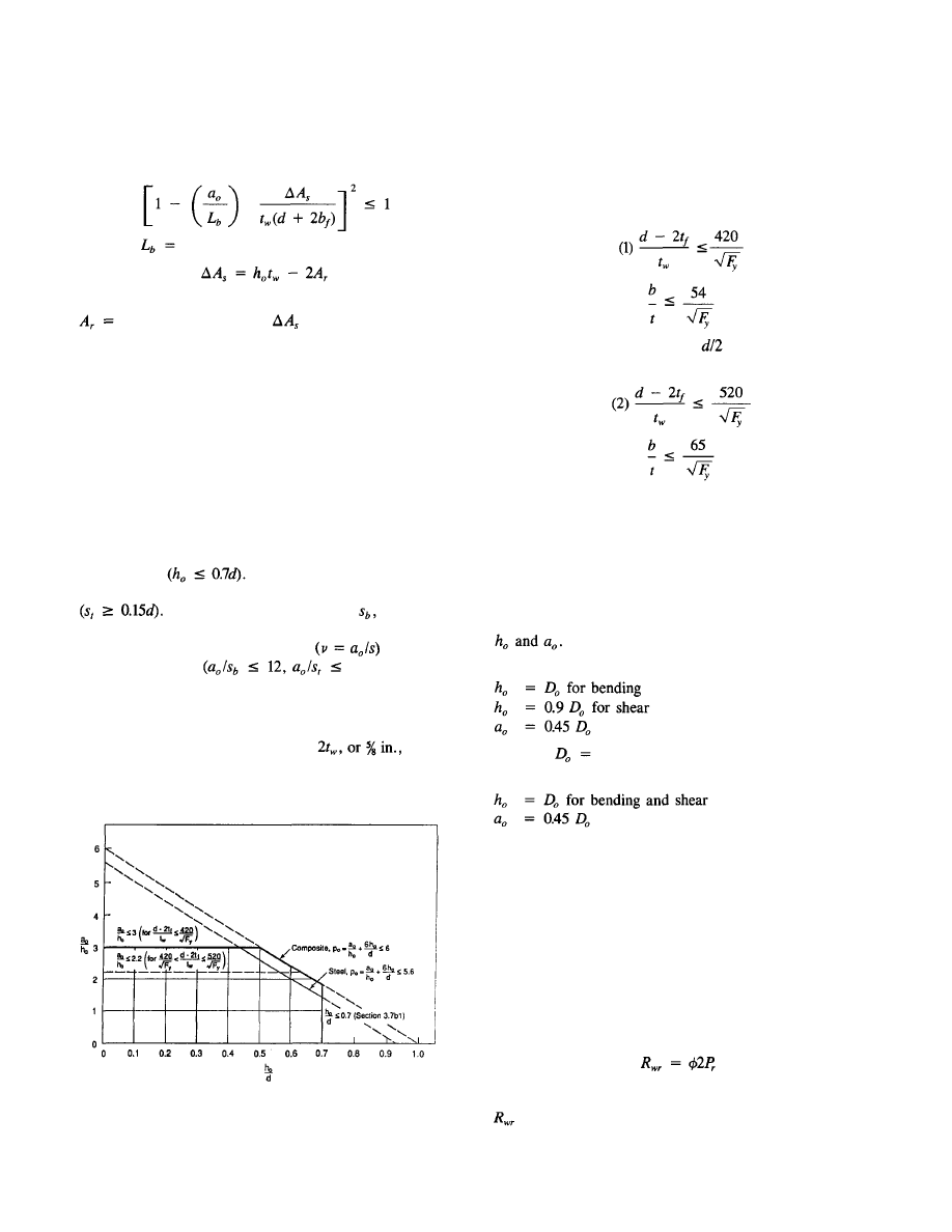
2. Web buckling
To prevent buckling of the web, two criteria should be met:
(a) The opening parameter,
should be limited to a
maximum value of 5.6 for steel sections and 6.0 for com-
posite sections.
(3-24)
in which
= length and width of opening, respec-
tively, d = depth of steel section
(b) The web width-thickness ratio should be limited as
follows
© 2003 by American Institute of Steel Construction, Inc. All rights reserved.
This publication or any part thereof must not be reproduced in any form without permission of the publisher.
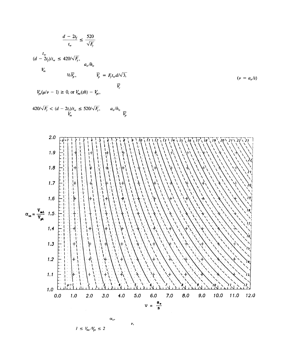
Fig. 3.8. Design aid relating
the ratio of the nominal maximum shear strength to the plastic
shear strength of the top tee, to
the length-to-depth ratio of the tee.
composite members only.
14
ling, along with an additional criterion from section 3.7bl,
are summarized in Fig. 3.9.
3. Buckling of tee-shaped compression zone
For steel beams only: The tee which is in compression should
be investigated as an axially loaded column following the
procedures of AISC (1986b). For unreinforced members this
is not required when the aspect ratio of the tee
is less than or equal to 4. For reinforced openings, this check
is only required for large openings in regions of high moment.
4. Lateral buckling
For steel beams only: In members subject to lateral buck-
ling of the compression flange, strength should not be
governed by strength at the opening (calculated without re-
gard to lateral buckling).
(3-25)
in which
= thickness of web
If
the web qualifies as stocky.
In this case, the upper limit on
is 3.0 and the upper
limit on
(maximum nominal shear capacity) for non-
composite sections is
in which the
plastic shear capacity of the unperforated web. For composite
sections, this upper limit may be increased by which
equals whichever
is
less.
All standard rolled W shapes (AISC 1986a) qualify as stocky
members.
If then
should
be limited to 2.2, and
should be limited to 0.45 for
both composite and non-composite members.
The limits on opening dimensions to prevent web buck-
© 2003 by American Institute of Steel Construction, Inc. All rights reserved.
This publication or any part thereof must not be reproduced in any form without permission of the publisher.
15
3. Concentrated loads
No concentrated loads should be placed above an opening.
Unless needed otherwise, bearing stiffeners are not re-
quired to prevent web crippling in the vicinity of an opening
due to a concentrated load if
(3-27a)
(3-27b)
and the load is placed at least
from the edge of the
opening,
or (3-28a)
(3-28b)
and the load is placed at least d from the edge of the opening.
In any case, the edge of an opening should not be closer
than a distance d to a support.
4. Circular openings
Circular openings may be designed using the expressions in
sections 3.5 and 3.6 by using the following substitutions for
Unreinforced web openings:
(3-29a)
(3-29b)
(3-29c)
in which
diameter of circular opening.
Reinforced web openings:
(3-30a)
(3-30b)
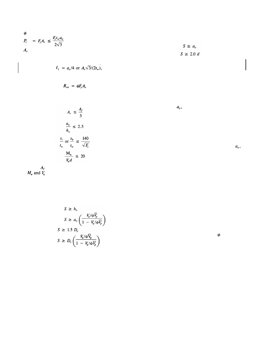
5. Reinforcement
Reinforcement should be placed as close to an opening as
possible, leaving adequate room for fillet welds, if required
on both sides of the reinforcement. Continuous welds should
be used to attach the reinforcement bars. A fillet weld may
be used on one or both sides of the bar within the length
of the opening. However, fillet welds should be used on both
sides of the reinforcement on extensions past the opening.
The required strength of the weld within the length of the
opening is,
(3-31)
in which
= required strength of the weld
In members with unreinforced openings or reinforced
openings with the reinforcement placed on both sides of the
web, the torsional constant, J, should be multiplied by
(3-26)
in which
unbraced length of compression flange
In members reinforced on only one side of the web,
0 for the calculation of
in Eq. 3-26. Members
reinforced on one side of the web should not be used for
long laterally unsupported spans. For shorter spans the lateral
bracing closest to the opening should be designed for an ad-
ditional load equal to 2 percent of the force in the compres-
sion flange.
b. Other considerations
1. Opening and tee dimensions
Opening dimensions are restricted based on the criteria in
section 3.7a. Additional criteria also apply.
The opening depth should not exceed 70 percent of the
section depth The
depth
of the top tee should
not be less than 15 percent of the depth of the steel section
The depth of the bottom tee, should
not
be less than 0.15d for steel sections or 0.l2d for composite
sections. The aspect ratios of the tees should
not
be greater than 12
12).
2. Comer radii
The corners of the opening should have minimum radii at
least 2 times the thickness of the web,
which-
ever is greater.
Fig. 3.9. Limits on opening dimensions.
© 2003 by American Institute of Steel Construction, Inc. All rights reserved.
This publication or any part thereof must not be reproduced in any form without permission of the publisher.
In addition to the requirements in Eqs. 3-37 and 3-38,
openings in composite beams should be spaced so that
(3-39a)
(3-39b)
c. Additional criteria for composite beams
In addition to the guidelines presented above, composite
members should meet the following criteria.
1. Slab reinforcement
Transverse and longitudinal slab reinforcement ratios should
be a minimum of 0.0025, based on the gross area of the slab,
within a distance d or
whichever is greater, of the open-
ing. For beams with longitudinal ribs, the transverse rein-
forcement should be below the heads of the shear connectors.
2. Shear connectors
In addition to the shear connectors used between the high
moment end of the opening and the support, a minimum of
two studs per foot should be used for a distance d or
whichever is greater, from the high moment end of the open-
ing toward the direction of increasing moment.
3. Construction loads
If a composite beam is to be constructed without shoring,
the section at the web opening should be checked for ade-
quate strength as a non-composite member under factored
dead and construction loads.
3.8 ALLOWABLE
STRESS DESIGN
The safe and accurate design of members with web open-
ings requires that an ultimate strength approach be used. To
accommodate members designed using ASD, the expressions
presented in this chapter should be used with =
1.00 and
a load factor of 1.7 for both dead and live loads. These fac-
tors are in accord with the Plastic Design Provisions of the
AISC ASD Specification (1978).
= 0.90 for steel beams and 0.85 for composite beams
= cross-sectional area of reinforcement above or be-
low the opening.
The reinforcement should be extended beyond the open-
ing by a distance
whichever is
greater, on each side of the opening (Figs 3.3 and 3.4). Within
each extension, the required strength of the weld is
(3-32)
If reinforcing bars are used on only one side of the
web, the section should meet the following additional
requirements.
(3-33)
(3-34)
(3-35)
(3-36)
in which
= area of flange
= factored moment and shear at centerline of
opening, respectively.
6. Spacing of openings
Openings should be spaced in accordance with the follow-
ing criteria to avoid interaction between openings.
Rectangular openings:
(3-37a)
(3-37b)
Circular openings:
(3-38a)
(3-38b)
in which S = clear space between openings.
16
Rev.
3/1/03
Rev.
3/1/03
© 2003 by American Institute of Steel Construction, Inc. All rights reserved.
This publication or any part thereof must not be reproduced in any form without permission of the publisher.
Chapter 4
DESIGN SUMMARIES AND EXAMPLE PROBLEMS
4.1 GENERAL
Equations for maximum bending capacity and details of
opening design depend on the presence or absence of a com-
posite slab and opening reinforcement. However, the over-
all approach, the basic shear strength expressions, and the
procedures for handling the interaction of bending and shear
are identical for all combinations of beam type and opening
configuration. Thus, techniques that are applied in the de-
sign of one type of opening can be applied to the design of all.
Tables 4.1 through 4.4 summarize the design sequence, de-
sign equations and design aids that apply to steel beams with
unreinforced openings, steel beams with reinforced openings,
composite beams with unreinforced openings, and compos-
ite beams with reinforced openings, respectively. Table 4.5
summarizes proportioning and detailing guidelines that ap-
ply to all beams.
Sections 4.2 through 4.6 present design examples. The ex-
amples in sections 4.2, 4.4, 4.5, and 4.6 follow the LRFD
approach. In section 4.3, the example in section 4.2 is re-
solved using the ASD approach presented in section 3.8.
A typical design sequence involves cataloging the proper-
ties of the section, calculating appropriate properties of the
opening and the tees, and checking these properties as de-
scribed in sections 3.7a and b. The strength of a section is
determined by calculating the maximum moment and shear
capacities and then using the interaction curve (Fig. A.1) to
determine the strength at the opening under the combined
effects of bending and shear.
Designs are completed by checking for conformance with
additional criteria in sections 3.7b and c.
17
Table 4.1
Design of Steel Beams with Unreinforced Web Openings
See sections 3.7a1-3.7b1 or Table 4.5 a1-b1 for proportioning guidelines.
Calculate maximum moment capacity: Use Eq. 3-6.
(3-6)
(3-13)
(3-12)
Calculate maximum shear capacity:
Check moment-shear interaction:
See sections 3.7b2-3.7b4 and 3.7b6 or Table 4.5b2-b4 and b6 for other guidelines.
© 2003 by American Institute of Steel Construction, Inc. All rights reserved.
This publication or any part thereof must not be reproduced in any form without permission of the publisher.
18
Table 4.2
Design of Steel Beams with Reinforced Web Openings
(3-7)
(3-8)
(3-13)
See sections 3.7al-3.7bl or Table 4.5 al-bl for proportioning guidelines.
Calculate maximum moment capacity: Use Eq. 3-7 or Eq. 3-8.
Check moment-shear interaction: Use Fig. A.1 with
See sections 3.7b2-3.7b6 or Table 4.5 b2-b6 for other guidelines.
Calculate maximum shear capacity:
© 2003 by American Institute of Steel Construction, Inc. All rights reserved.
This publication or any part thereof must not be reproduced in any form without permission of the publisher.
Table 4.3
Design of Composite Beams with Unreinforced Web Openings
See sections 3.7a1, 3.7a2, and 3.7b1 or Table 4.5 a1-a3 for proportioning guidelines.
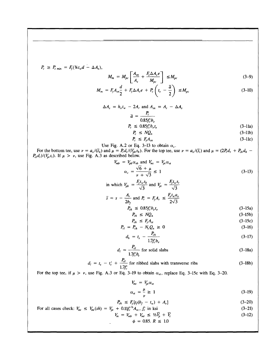
Calculate maximum moment capacity: Use Eq. 3-9 or Eq. 3-10.
When PNA in unperforated member is above top of flange, use Eq. 3-9 or Eq. 3-10. When PNA in unperforated
member is below top of flange and
use Eq. 3-10.
(3-9)
(3-10)
in which M
pc
= Plastic bending capacity of unperforated composite beam
and
(3-11a)
(3-11b)
(3-11c)
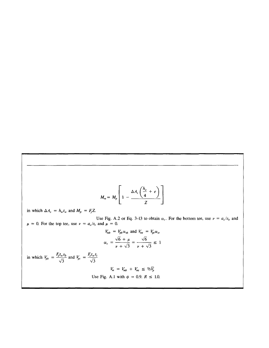
Calculate maximum shear capacity: Use Fig. A.2 or Eq. 3-13 to obtain
For the bottom tee, use
and
For the top tee, use
and
If
use Fig. A.3 as described below.
(3-13)
(3-15a)
(3-15b)
(3-15c)
(3-16)
(3-17)
(3-18a)
(3-18b)
for ribbed slabs with transverse ribs
For the top tee, if
use Fig. A.3 or Eq. 3-19 to obtain and
replace Eq. 3-15c with Eq. 3-20, with
(3-19)
(3-20)
For all cases check:
(3-21)
(3-12)
Check moment-shear interaction: Use Fig. A.1 with
See sections
and
or Table
and
for other guidelines.
19
© 2003 by American Institute of Steel Construction, Inc. All rights reserved.
This publication or any part thereof must not be reproduced in any form without permission of the publisher.
20
Table 44
Design of Composite Beams with Reinforced Web Openings
See sections 3.7al, 3.7a2, and 3.7bl or Table 4.5 al-a3 for proportioning guidelines.
Calculate maximum moment capacity: Use Eq. 3-9 or Eq. 3-10.
When PNA in unperforated member is above top of flange, use Eq. 3-9 or Eq. 3-10. When PNA in unperforated
member is above top of flange, use Eq. 3-9 or Eq. 3-10. When PNA in unperforated member is below top of flange
and use
Eq. 3-10.
in which M
pc
= Plastic bending capacity of unperforated composite beam
Calculate maximum shear capacity:
Check moment-shear interaction: Use Fig. A.1 with
See sections 3.7b2-3.7c3 or Table 4.5 b2-c3 for other guidelines.
© 2003 by American Institute of Steel Construction, Inc. All rights reserved.
This publication or any part thereof must not be reproduced in any form without permission of the publisher.
Table 4.5
Summary of Proportioning and Detailing Guidelines
These guidelines apply to both steel and composite members, unless noted otherwise.
a. Section properties and limits on
1. Beam dimensions and limits on
(a) Width to thickness ratios of compression flange and web reinforcement, must not exceed
65 ksi) (section 3.7al).
(b) The width to thickness ratio of the web, ,
must not exceed .
If
the
ratio is
must not exceed 3.0, and
must not exceed for
steel
beams +
for
composite
beams.
If the ratio is
must not exceed 2.2, and
must not exceed 0.45
whichever is less] (section 3.7a2).
2. Opening dimensions (See Fig. 3.9)
(a) Limits on
are given in a.l.(b) above.
(b) must
not
exceed
(section 3.7bl).
(c) The opening parameter,
must not exceed 5.6 for steel beams or 6.0 for composite
beams (section 3.7a2).
3. Tee dimensions
(a) Depth
(composite)] (section 3.7bl).
(b) Aspect ratio (section
3.7bl).
b. Other considerations
1. Stability considerations. Steel beams only
(a) Tees in compression must be designed as axially loaded columns. Not required for unreinforced openings if
4 or for reinforced openings, except in regions of high moment (section 3.7a3).
(b) See requirements in section 3.7a4 for tees that are subject to lateral buckling.
2. Corner radii
Minimum radii = the greater of
(section 3.7b2).
3. Concentrated loads
No concentrated loads should be placed above an opening. Edge of opening should not be closer than d to a sup-
port. See section 3.7b3 for bearing stiffener requirements.
4. Circular openings
See section 3.7b4 for guidelines to design circular openings as equivalent rectangular openings.
5. Reinforcement
See section 3.7b5 for design criteria for placement and welding of reinforcement.
6. Spacing of openings
See section 3.7b6 for minimum spacing criteria.
c. Additional criteria for composite beams
1. Slab reinforcement
Minimum transverse and longitudinal slab reinforcement ratio within d or
(whichever is greater) of the open-
ing is 0.0025, based on gross area of slab. For beams with longitudinal ribs, the transverse reinforcement should
be below the heads of the shear connectors (section 3.7cl).
2. Shear connectors
In addition to shear connectors between the high moment end of opening and the support, use a minimum of two
studs per foot for a distance d or
(whichever is greater) from high moment end of opening toward direction
of increasing moment (section 3.7c2).
3. Construction loads
Design the section at the web opening as a non-composite member under factored dead and construction loads,
if unshored construction is used (section 3.7c3)
21
© 2003 by American Institute of Steel Construction, Inc. All rights reserved.
This publication or any part thereof must not be reproduced in any form without permission of the publisher.
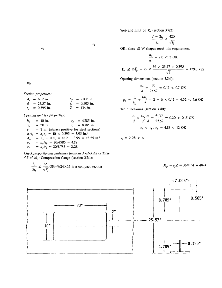
4.2 EXAMPLE
1:
STEEL BEAM WITH
UNREINFORCED OPENING
A W24X55 section supports uniform loads =
0.607
kips/ft and
= 0.8 kips/ft on a 36-foot simple span. The
beam is laterally braced throughout its length. ASTM A36
steel is used.
Determine where an unreinforced 10x20 in. rectangular
opening with a downward eccentricity of 2 in. (Fig. 4.1) can
be placed in the span.
Loading:
= 1.2 X 0.607 + 1.6 x 0.8 = 2.008 kips/ft
Shear and moment diagrams are shown in Fig. 4.2.
Buckling of tee-shaped compression zone (section 3.7a3):
Check not required
Lateral buckling (section 3.7a4): No requirement, since
compression flange is braced throughout its length
Maximum moment capacity:
For the unperforated section:
in.-kips
Fig. 4.1. Details for Example I.
22
© 2003 by American Institute of Steel Construction, Inc. All rights reserved.
This publication or any part thereof must not be reproduced in any form without permission of the publisher.
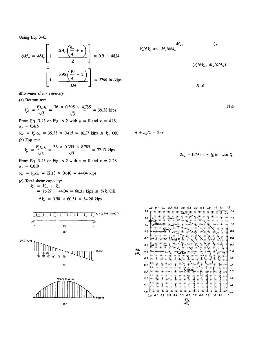
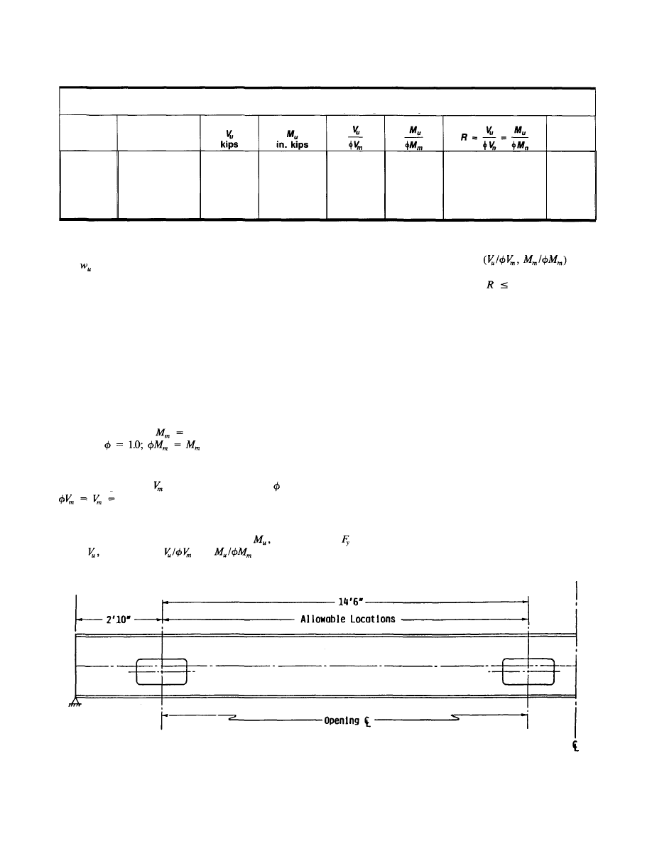
Allowable locations of opening:
The factored moment,
factored shear,
and values
of
will be tabulated at 3-ft intervals
across the beam.
To determine if the opening can be placed at each loca-
tion, the R value for each point is
ob-
tained from the interaction diagram, Fig. A.1.
Figure A.1 is duplicated in Fig. 4.3, which shows the lo-
cation of each point on the interaction diagram. The open-
ing may be placed at a location if
1. The results are
presented in Table 4.6. The acceptable range for opening lo-
cations is illustrated in Fig. 4.4.
Table 4.6 shows that the centerline of the opening can be
placed between the support and a point approximately ft
from the support, on either side of the beam. The opening
location is further limited so that the edge of the opening
can be no closer than a distance d to the support (section
3.7b3). Thus, the opening centerline must be located at least
in., say 34 in., from the support (section
3.7b2).
Corner radii:
The corner radii must be
or
larger.
4.3 EXAMPLE
1A:
STEEL BEAM WITH
UNREINFORCED OPENING—ASD
APPROACH
Repeat Example 1 using the ASD Approach described in sec-
tion 3.8.
Fig. 4.2. Shear and moment diagrams for Example 1.
Fig. 4.3. Moment-shear interaction diagram for Example 1.
23
© 2003 by American Institute of Steel Construction, Inc. All rights reserved.
This publication or any part thereof must not be reproduced in any form without permission of the publisher.
Loading:
= 1.7 X 0.607 + 1.7 x 0.8 = 2.392 kips/ft
The values of factored shear and moment in Example 1 are
thus multiplied by the factor 2.392/2.008 = 1.191.
Section properties, opening and tee properties:
See Example 1.
Check proportioning guidelines (section 3.7al-3.7bl or
Table 4.5 al-bl):
See Example 1.
Maximum moment capacity:
From Example 1, 0.9
3766 in.-kips.
For ASD,
= 4184 in.-kips.
Maximum shear capacity:
From Example 1, 0.9
= 54.28 kips. For ASD, =
1.0;
60.31 kips.
Allowable locations of openings:
As with Example 1, the factored moment
factored
shear, and
values
of
and
will
be
tabu-
lated at 3-ft intervals across the beam.
To determine if the opening can be placed at each loca-
tion, the R value for each point is
ob-
tained from the interaction diagram, Fig. A.1. The opening
may be placed at a location if
1. The results are
presented in Table 4.7.
Table 4.7 shows that the centerline of the opening can be
placed between the support and a point 12 ft from the sup-
port, on either side of the beam. This compares to a value
of 14.6 ft obtained in Example 1 using the LRFD approach.
As in Example 1, the opening location is further limited so
that the edge of the opening can be no closer than a distance
d = 34 in. to the support (section 3.7b3).
Corner radii (section 3.7b2): See Example 1.
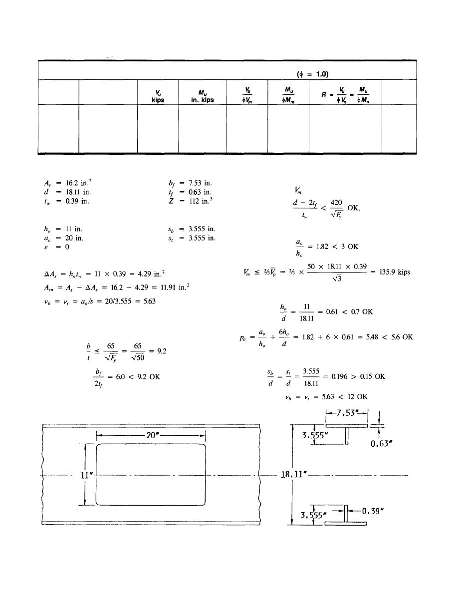
44 EXAMPLE
2:
STEEL BEAM WITH
REINFORCED OPENING
A concentric 11x20 in. opening must be placed in a Wl8x55
section (Fig. 4.5) at a location where the factored shear is
30 kips and the factored moment is 300 ft-kips (3600 in.-
kips). The beam is laterally braced throughout its length.
= 50 ksi.
Can an unreinforced opening be used? If not, what rein-
forcement is required?
Fig. 4.4. Allowable opening locations for Example 1.
24
Table 4.6
Allowable Locations for Openings, Example 1
Point
Distance
from
Support, ft
1
2
3
4
5
6
3
6
9
12
15
18
30.1
24.1
18.1
12.0
6.0
0
1192
2169
2928
3470
3795
3903
0.555
0.444
0.346
0.223
0.111
0
0.317
0.576
0.778
0.921
1.008
1.036
<0.60
0.65
0.80
0.93
1.01
1.04
OK
OK
OK
OK
NG
NG
© 2003 by American Institute of Steel Construction, Inc. All rights reserved.
This publication or any part thereof must not be reproduced in any form without permission of the publisher.
been skipped. If reinforcement is needed, the reinforcement
must meet this requirement.)
Web and limit on
(section 3.7a2):
Fig. 4.5. Details for Example 2.
25
1
2
3
4
5
6
3
6
9
12
15
18
35.8
28.7
22.4
14.4
7.1
0
1418
2581
3484
4129
4516
4645
0.594
0.476
0.371
0.239
0.118
0
0.339
0.617
0.833
0.987
1.079
1.110
0.63
0.70
0.86
1.00
1.08
1.11
OK
OK
OK
OK
NG
NG
Table 4.7
Allowable Locations for Openings, Example 1A
Point
Distance
from
Support, ft
Section properties:
Opening and tee properties:
Without reinforcement,
since all W shapes meet this requirement
Check proportioning guidelines (sections 3.7al-3.7bl or Table
4.5 al-bl):
Compression flange and reinforcement (section 3.7al):
(Since a W18x35 is a compact section this check could have
Opening dimensions (section 3.7bl):
Tee dimensions (section 3.7bl):
© 2003 by American Institute of Steel Construction, Inc. All rights reserved.
This publication or any part thereof must not be reproduced in any form without permission of the publisher.
Buckling of tee-shaped compression zone (section 3.7a3):
4. Check for buckling if reinforcement is not
used.
Lateral buckling (section 3.7a4): No requirement, since
compression flange is braced throughout its length.
Maximum moment capacity:
For the unperforated section:
5600 in.-kips
Using Eq. 3-6,
Design reinforcement and check strength:
Reinforcement should be selected to reduce R to 1.0. Since
the reinforcement will increase of
a
steel
member only
slightly, the increase in strength will be obtained primarily
through the effect of the reinforcement on the shear capac-
ity,
remains at approximately 0.79, R = 1.0
will occur for
0.80 (point 1 on Fig. 4.6).
Try
From Fig. A.1 (Fig. 4.6, point 2), R = 0.96
1.0 OK
The section has about 4 percent excess capacity.
26
Maximum shear capacity:
Bottom and top tees:
Check interaction:
By inspection, R > 1.0. The strength is not adequate and
reinforcement is required.
Check strength:
(a) Maximum moment capacity:
(b) Maximum shear capacity:
(c) Check interaction:
© 2003 by American Institute of Steel Construction, Inc. All rights reserved.
This publication or any part thereof must not be reproduced in any form without permission of the publisher.
= 0.90 × 50 × 0.656 = 29.5 kips within each ex-
tension. Use extensions of
= 20/4 = 5 in.,
× 0.656/(2 × 0.39) = 1.46 in. Use 5 in.
The total length of the reinforcement = 20.0 + 2 × 5.0 =
30.0 in.
Assume E70XX electrodes, which provide a shear strength
of the weld metal
= 0.60 × 70 = 42 ksi (AISC 1986a).
A fillet weld will be used on one side of the reinforcement
bar, within the length of the opening. Each
in. weld will
provide a shear capacity of
× 0.707 ×
= 0.75 ×
42 × 20 × 0.707 ×
= 27.8 kips.
For =
59.0
kips, with the reinforcement on one side
of the web, 59.0/27.8 = 2.12 sixteenths are required. Use
a in.
fillet
weld. [Note the minimum size of fillet weld
for this material is
in.]. Welds should be used on both
sides of the bar in the extensions. By inspection, the weld
size is identical.
According to AISC (1986b), the shear rupture strength of
the base metal must also be checked. The shear rupture
strength =
, in which
= 0.75,
tensile strength of base metal, and
= net area subject
to shear. This requirement is effectively covered for the steel
section by the limitation that
which is
based on
= 0.90 instead of = 0.75, but uses
0.58 in
place
of
.
For
the
reinforcement, the shear
rupture force 52.7
kips.
0.75 × 0.6 × 58 ksi ×
in. = =196 kips
52.7, OK.
The completed design is illustrated in Fig. 4.7.
4.5 EXAMPLE
3: COMPOSITE BEAM
WITH UNREINFORCED OPENING
Simply supported composite beams form the floor system
of an office building. The 36-ft beams are spaced 8 ft apart
and support uniform loads of
= 0.608 kips/ft and
0.800 kips/ft. The slab has a total thickness of 4 in. and will
be placed on metal decking. The decking has 2 in. ribs on
12 in. centers transverse to the steel beam. An A36 W21×44
steel section and normal weight concrete will be used. Nor-
mal weight concrete (w = 145
= 3 ksi will
be used.
Can an unreinforced 11×22 in. opening be placed at the
quarter point of the span? See Fig. 4.8.
27
Select reinforcement:
Check to see if reinforcement may be placed on one side
of web (Eqs. 3-33 through 3-36):
Fig. 4.6. Moment-shear interaction diagram for Example 2.
Therefore, reinforcement may be placed on one side of the
web.
From the stability check [Eq. (3-22)], 9.2.
Use
Comer radii (section 3.7b2) and weld design:
The corner radii must be
= 0.78 in.
in. Use
in.
or larger.
The weld must develop
0.90 × 2 × 32.8 =
59.0 kips within the length of the opening and
Loading:
= 1.2 × 0.608 + 1.6 × 0.800 = 2.01 kips/ft
At the quarter point:
18.1 kips
Rev.
3/1/03
© 2003 by American Institute of Steel Construction, Inc. All rights reserved.
This publication or any part thereof must not be reproduced in any form without permission of the publisher.
0.75 x 0.6 x 58 ksi x 3/8 in. x 120 in.
Fig. 4.7. Completed design of reinforced opening for Example 2.
28
Shear connector parameters:
Use
in. studs (Note: maximum allowable stud height
is used to obtain the maximum stud capacity). Following the
procedures in AISC (1986b),
Opening and tee properties:
(positive upward for composite members)
Try 1 stud per rib:
Check proportioning guidelines (sections 3.7al, 3.7a2, and
3.7bl or Table 4.5 a1-a3):
Compression flange (section 3.7a1):
OK, since all W shapes meet this requirement
Opening dimensions (section 3.7b1):
© 2003 by American Institute of Steel Construction, Inc. All rights reserved.
This publication or any part thereof must not be reproduced in any form without permission of the publisher.
29
Tee dimension (section 3.7bl):
Maximum moment capacity:
Use Eqs. 3-11a, 3-11b, and 3-11c to calculate the force in
the concrete:
By inspection, the PNA in the unperforated section will
be below the top of the flange. Therefore, use Eq. 3-10 to
calculate
Maximum shear capacity:
(a) Bottom tee:
(b) Top Tee:
The value of µ must be calculated for the top tee.
The net area of steel in the top tee is
The force in the concrete at the high moment end of the
opening is obtained using Eqs. 3-15a, b and c.
Fig. 4.8. Details for Example 3.
© 2003 by American Institute of Steel Construction, Inc. All rights reserved.
This publication or any part thereof must not be reproduced in any form without permission of the publisher.
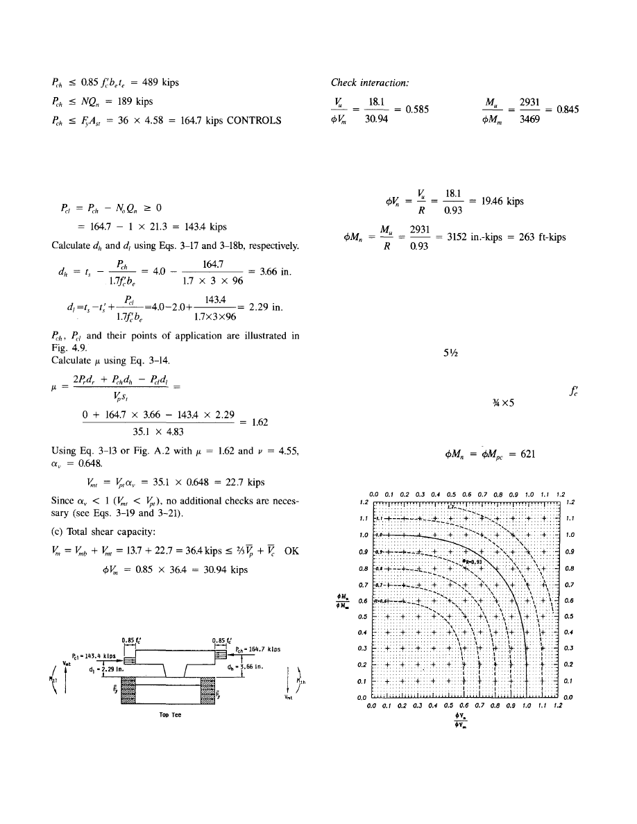
Fig. 4.9. Top tee under maximum shear for Example 3.
Fig. 4.10. Moment-shear interaction diagram for Example 3.
30
Using Fig. A.1 (reproduced in Fig. 4.10) the point (0.585,
0.845) yields a value of R = 0.93. Therefore, the opening
can be placed at the quarter point of the span.
The design shear and moment capacities at the opening are
4.6 EXAMPLE
4:
COMPOSITE GIRDER
WITH UNREINFORCED AND
REINFORCED OPENINGS
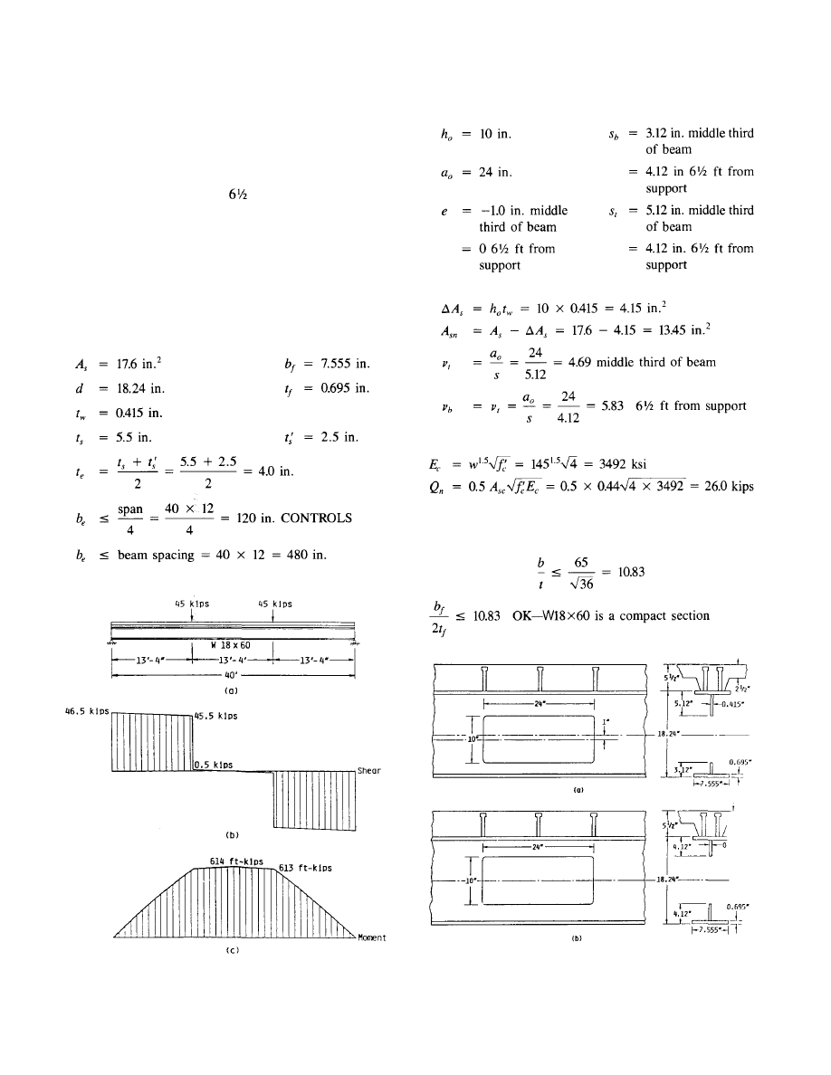
A 40-foot simply-supported composite girder supports fac-
tored loads of 45 kips at its third points [Fig. 4.11(a)]. The
slab has a total thickness of
in. and is cast on metal deck-
ing with 3 in. deep ribs that are parallel to the A36 W18X60
steel beam. The ribs are spaced at 12 in., and the girders
are spaced 40 ft apart. The concrete is normal weight;
= 4 ksi. The design calls for pairs of
in. shear studs
spaced every foot in the outer third of the girder, starting
6 in. from the support, and single studs every foot in the
middle third of the girder. The design moment capacity of
the unperforated member,
ft-kips in
the middle third of the member.
The force in the concrete at the low moment end of the
opening is obtained using Eq. 3-16. Assume minimum num-
ber of ribs = one rib over the opening. (Note: It is possible
to locate two ribs over the opening, but for now use the con-
servative assumption.)
© 2003 by American Institute of Steel Construction, Inc. All rights reserved.
This publication or any part thereof must not be reproduced in any form without permission of the publisher.
1. Can an unreinforced 10x24 in. opening with a down-
ward eccentricity of 1 in. [Fig. 4.12(a)] be placed in
the middle third of the beam? If not, how much rein-
forcement is necessary?
2. Can a concentric unreinforced opening of the same size
[Fig. 4.12(b)] be placed
ft from the centerline of
the support? If not, how much reinforcement is
required?
Loading:
The factored shear and moment diagrams are shown in Figs
4.11 (b) and (c).
Fig. 4.11. Shear and moment diagrams for Example 4.
Fig. 4.12. Details for Example 4. (a) Eccentric opening,
(b) concentric opening.
31
Section properties:
Opening and tee properties:
Without reinforcement,
Shear connector strength:
Check proportioning guidelines (sections 3.7al, 3.7a2, and
3.7a3 or Table 4.5 a1-a3):
Compression flange and reinforcement (section 3.7a1):
© 2003 by American Institute of Steel Construction, Inc. All rights reserved.
This publication or any part thereof must not be reproduced in any form without permission of the publisher.
in middle third OK, by inspection, ft
from support
1. Opening
in
middle one-third of beam
Figure 4.11(b) shows that the shear is very low and the mo-
ment is very nearly constant in the middle third of the girder.
The maximum factored moment is 614 ft-kips (7368 in-kips),
which is very close to
= 621 ft-kips (7452 in .-kips)
for unperforated section. Reinforcement will be required to
compensate for the opening. Since the section is in nearly
pure bending, the reinforcement will be selected based on
bending alone, i.e.,
The PNA in the unperforated section is above the top of
the flange. Therefore, Eq. 3-9 can be used to calculate the
required area of reinforcement. (It should be very close to
the area removed by the opening.)
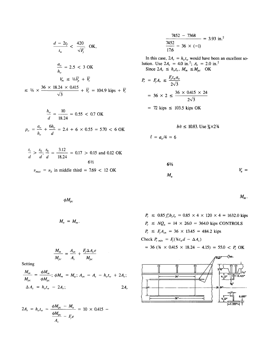
Fig. 4.13. Completed design of reinforced, eccentric opening
located in middle one-third of beam in Example 4.
32
A check of Eqs. 3-33 through 3-36 shows that the rein-
forcement must be placed on both sides of the web. To pre-
vent local buckling, in.
bars
on
each
side of the web, above and below the opening. Extend the
bars in.
on
either side of the opening for a
total length of 36 in. Design the welds in accordance with
Eqs. 3-31 and 3-32 (see Example 2).
The completed design is illustrated in Fig. 4.13.
2. Opening
ft from support
The eccentricity is zero at this location [Fig. 4.12(b)].
46.0 kips and
= 300 ft-kips (3600 in-kips) (Fig. 4.11).
Maximum moment capacity without reinforcement:
The PNA is below the top of the flange in the unperforated
section. Therefore, Eq. 3-10 will be used to calculate
The force in the concrete is obtained using Eqs. 3-11 a, b,
and c.
Web and limits on V
m
(section 3.7a2):
since all W shapes meet this requirement
Opening dimensions (section 3.7bl):
Tee dimensions (section 3.7b1):
substituting and solving for
gives an expression for the total area of reinforcement needed
to provide the required bending strength.
© 2003 by American Institute of Steel Construction, Inc. All rights reserved.
This publication or any part thereof must not be reproduced in any form without permission of the publisher.
(b) Top tee:
The value of [Eq. 3-14] must be calculated for the top tee.
The force at the high moment end of the opening, is
obtained using Eqs. 3-15a, b, and c. Noting that Eqs. 3-15a
and b are the same as Eqs. 3-1 1a and b, the limitations based
on concrete and stud capacity are identical to those obtained
for
in the calculation of
above. This leaves Eq.
3-15c.
242 kips CONTROLS
The force in the concrete at the low moment end of the
opening, is
obtained using Eq. 3-16. With the shear
studs placed in pairs every foot, starting 6 in. from the cen-
terline of the support,
Note that the definitions for
N and N
0
require the studs to be completely within the ap-
plicable range to be counted. This means that the studs lo-
cated just at the ends of the opening are not included in
and the studs at the high moment end of the opening are not
counted in N.
the distances from the top of the flange to the
centroids of
respectively, are calculated using
Eqs. 3-17 and 3-18a. Since the ribs are parallel to the steel
beams, in
Eq.
3-18a is conservatively replaced by
the sum of the minimum rib widths that lie within
Since Eq.
3-19 or Fig A.3 should be used to calcu-
late In
addition,
when is
limited by the ten-
sile capacity of the flange plus reinforcement (if any),
Eq. 3-20.
This value is less than the current value of
(242 kips).
Therefore, must
also be recalculated. The
new values are as follows:
By inspection, the section does not have adequate strength.
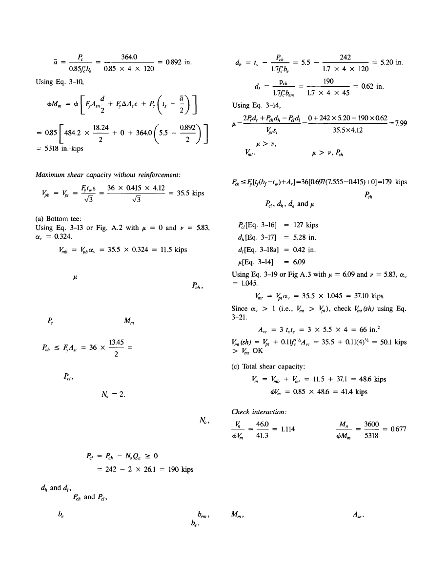
Using Fig A.1 (reproduced in Fig. 4.14), the point (1.114,
0.674), point 1 on Fig. 4.14, yields a value of R = 1.21> 1.
Design reinforcement and check strength:
The addition of reinforcement will increase the capacity at
the opening in a number of ways: The moment capacity,
will be enhanced due to the increase
The shear ca-
pacity of the bottom tee will be enhanced due to the increase
33
© 2003 by American Institute of Steel Construction, Inc. All rights reserved.
This publication or any part thereof must not be reproduced in any form without permission of the publisher.
in from
0
to
And
the
shear capacity of the top
tee will be enhanced due to increases in from the addition
of and an increase in
The increase in
is obtained
because its value is currently limited by the tensile capacity
of the top flange alone (Eq. 3-20).
Fig. 4.14. Moment-shear interaction diagram for opening located
ft from support in Example 4.
34
Maximum moment capacity:
Use Eqs. 3-11a, 3-11b, and 3-11c to calculate the force in
the concrete:
Maximum shear capacity:
(a) Bottom tee:
(b) Top tee:
Use Eq. 3-14 to calculate µ.
© 2003 by American Institute of Steel Construction, Inc. All rights reserved.
This publication or any part thereof must not be reproduced in any form without permission of the publisher.
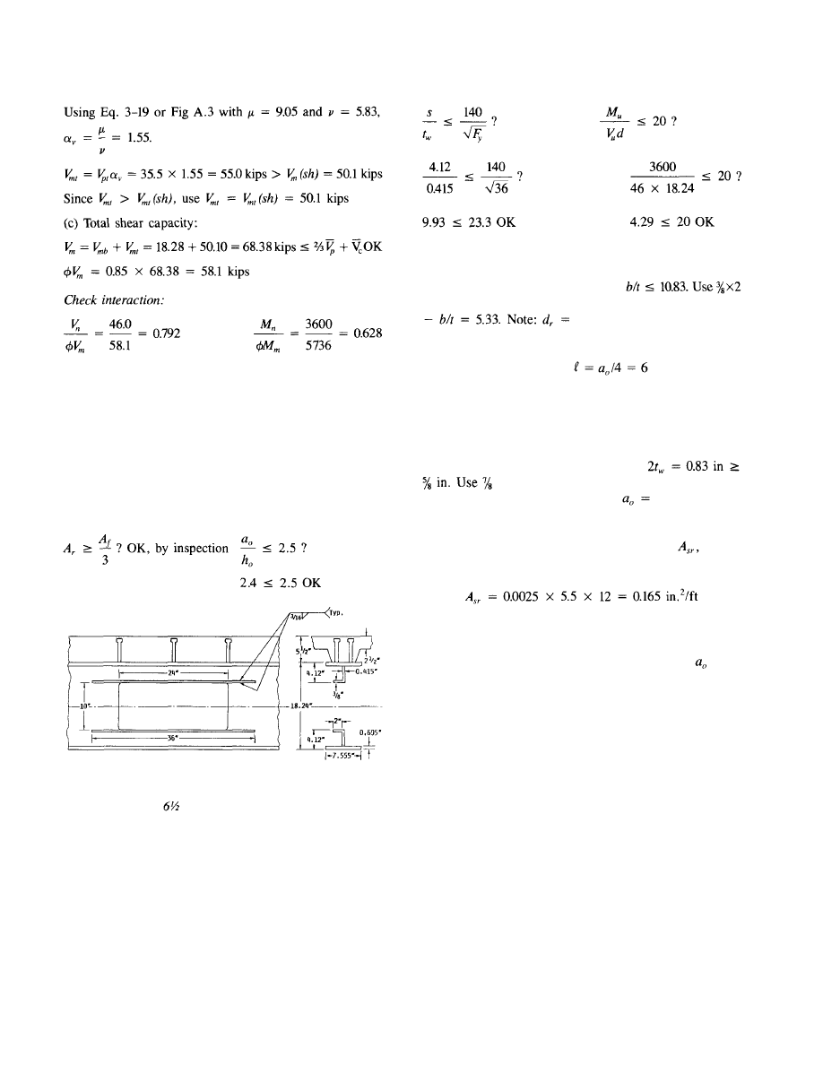
Using Fig A.1, the point (0.792, 0.628), point 2 in Fig. 4.14,
yields a value of R = 0.905 < 1 OK. In fact, the section
now has about 10 percent excess capacity. If this opening
detail will be used many times in the structure, it would be
worthwhile to improve the design by reducing the area of
reinforcement.
Select reinforcement:
Check to see if reinforcement may be placed on one side
of the web (Eqs. 3-33 through 3-36).
Fig. 4.15. Completed design of reinforced, concentric opening
located
ft from support in Example 4.
Therefore, reinforcement may be placed on one side of the
web.
From the stability check (Eq. 3-22),
in. bar on one side of the web, above and below the opening
3.93 in. and is somewhat less
than the value originally assumed. However, the section ca-
pacity is clearly adequate.
Extend the reinforcement
in. on either side
of the opening for a total length of 36 in. Design the welds
in accordance with Eqs. 3-31 and 3-32 (see Example 2).
Other considerations:
The corner radii (section 3.7b2) must be
in. or larger.
Within a distance d = 18.24 in. or
24 in. (controls)
of the opening, the slab reinforcement ratio should be a mini-
mum of 0.0025, based on the gross area of the slab (section
3.7cl). The required area of slab reinforcement, in
both
logitudinal and transverse directions is
In addition to the shear connectors between the high mo-
ment end of the opening and the support, a minimum of two
studs per foot should be used for a distance d or
(con-
trols in this case) from the high moment end of the opening
toward the direction of increasing moment (section 3.7c2).
This requirement is satisfied by the original design, which
calls for pairs of studs spaced at 1 foot intervals in the outer
thirds of the beam.
Finally, if shoring is not used, the beam should be checked
for construction loads as a non-composite member (section
3.7c3).
The completed design is illustrated in Fig 4.15.
35
© 2003 by American Institute of Steel Construction, Inc. All rights reserved.
This publication or any part thereof must not be reproduced in any form without permission of the publisher.
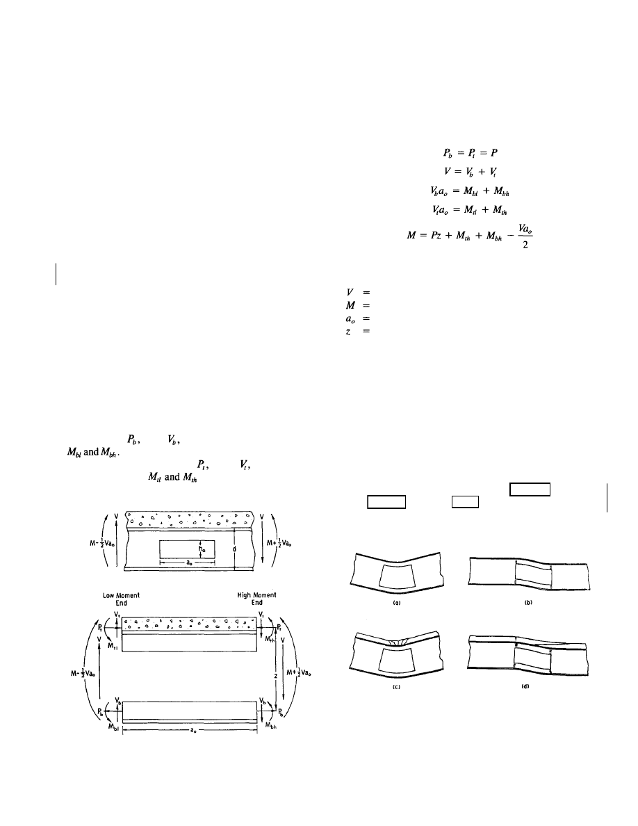
Chapter 5
BACKGROUND AND COMMENTARY
5.1 GENERAL
This chapter provides the background and commentary for
the design procedures presented in Chapter 3. Sections 5.2a
through 5.2g summarize the behavior of steel and compos-
ite beams with web openings, including the effects of open-
ings on stress distributions, modes of failure, and the gen-
eral response of members to loading. Section 5.2h provides
the commentary for section 3.2 on load and resistance fac-
tors, while sections 5.3 through 5.7 provide the commentary
for sections 3.3 through 3.7 on design equations and guide-
lines for proportioning and detailing beams with web
openings.
5.2 BEHAVIOR
OF MEMBERS WITH
WEB OPENINGS
a. Forces
acting
at
opening
The forces that act at opening are shown in Fig. 5.1. In the figure,
a composite beam is illustrated, but the equations that follow
pertain equally well to steel members. For positive bending,
the section below the opening, or bottom tee, is subjected to
a tensile force,
shear, and
secondary bending moments,
The section above the opening, or top tee, is sub-
jected to a compressive force,
shear, and secondary
bending moments, .
Based on equilibrium,
b. Deformation
and
failure modes
The deformation and failure modes for beams with web open-
ings are illustrated in Fig. 5.2. Figures 5.2(a) and 5.2(b) illus-
trate steel beams, while Figs. 5.2(c) and 5.2(d) illustrate com-
pbsite beams with solid slabs.
High moment-shear ratio
The behavior at an opening depends on the ratio of moment
to shear, M/V (Bower 1968, Cho 1982, Clawson & Darwin
1980, Clawson & Darwin 1982a, Congdon & Redwood 1970,
Donahey & Darwin 1986, Donahey & Darwin 1988, Granada
1968).
Fig. 5.2. Failure modes at web openings, (a) Steel beam, pure
bending, (b) steel beam, low moment-shear ratio,
(c) composite beam with solid slab, pure bending,
(d) composite beam with solid slab, low moment-
shear ratio.
37
Fig. 5.1. Forces acting at web opening.
(5-1)
(5-2)
(5-3)
(5-4)
(5-5)
in which
total shear acting at an opening
primary moment acting at opening center line
length of opening
distance between points about which secondary bend-
ing moments are calculated
Rev.
3/1/03
Rev.
3/1/03
© 2003 by American Institute of Steel Construction, Inc. All rights reserved.
This publication or any part thereof must not be reproduced in any form without permission of the publisher.
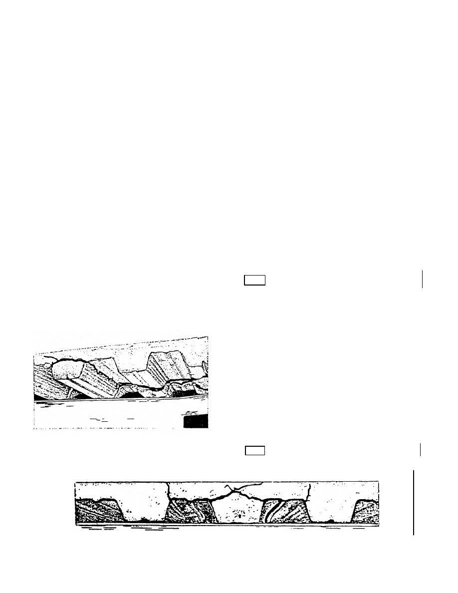
Medium and low moment-shear ratio
As M/V decreases, shear and the secondary bending moments
increase, causing increasing differential, or Vierendeel, defor-
mation to occur through the opening [Figs. 5.2(b) and 5.2(d)].
The top and bottom tees exhibit a well-defined change in
curvature.
For steel beams [Fig. 5.2(b)], failure occurs with the for-
mation of plastic hinges at all four corners of the opening.
Yielding first occurs within the webs of the tees.
For composite beams [Fig. 5.2(d)], the formation of the plas-
tic hinges is accompanied by a diagonal tension failure within
the concrete due to prying action across the opening. For mem-
bers with ribbed slabs, the diagonal tension failure is
manifested as a rib separation and a failure of the concrete
around the shear connectors (Fig. 5.3). For composite mem-
bers with ribbed slabs in which the rib is parallel to the beam,
failure is accompanied by longitudinal shear failure in the slab
(Fig. 5.4).
For members with low moment-shear ratios, the effect of
secondary bending can be quite striking, as illustrated by the
stress diagrams for a steel member in Fig. 5.5 (Bower 1968)
and the strain diagrams for a composite member with a ribbed
slab in Fig. 5.6 (Donahey & Darwin 1986). Secondary bend-
ing can cause portions of the bottom tee to go into compres-
sion and portions of the top tee to go into tension, even though
the opening is subjected to a positive bending moment. In com-
posite beams, large slips take place between the concrete deck
and the steel section over the opening (Fig. 5.6). The slip is
enough to place the lower portion of the slab in compression
Fig. 5.3. Rib failure and failure of concrete around shear
connectors in slab with transverse ribs.
at the low moment end of the opening, although the adjacent
steel section is in tension. Secondary bending also results in
tensile stress in the top of the concrete slab at the low moment
end of the opening, which results in transverse cracking.
Failure
Web openings cause stress concentrations at the corners of the
openings. For steel beams, depending on the proportions of
the top and bottom tees and the proportions of the opening
with respect to the member, failure can be manifested by gen-
eral yielding at the corners of the opening, followed by web
tearing at the high moment end of the bottom tee and the low
moment end of the top tee (Bower 1968, Congdon & Red-
wood 1970, Redwood & McCutcheon 1968). Strength may
be reduced or governed by web buckling in more slender
members (Redwood et al. 1978, Redwood & Uenoya 1979).
In high moment regions, compression buckling of the top
tee is a concern for steel members (Redwood & Shrivastava
1980). Local buckling of the compression flange is not a con-
cern if the member is a compact section (AISC 1986b).
For composite beams, stresses remain low in the concrete
until well after the steel has begun to yield (Clawson & Dar-
win 1982a, Donahey & Darwin 1988). The concrete contrib-
utes significantly to the shear strength, as well as the flex-
ural strength of these beams at web openings. This contrasts
with the standard design practice for composite beams, in
which the concrete deck is used only to resist the bending
moment, and shear is assigned solely to the web of the steel
section.
For both steel and composite sections, failure at web open-
ings is quite ductile. For steel sections, failure is preceded
by large deformations through the opening and significant
yielding of the steel. For composite members, failure is
preceded by major cracking in the slab, yielding of the steel,
and large deflections in the member.
First yielding in the steel does not give a good repre-
sentation of the strength of either steel or composite sec-
tions. Tests show that the load at first yield can vary from
35 to 64 percent of the failure load in steel members (Bower
1968, Congdon & Redwood 1970) and from 17 to 52 percent
of the failure load in composite members (Clawson & Dar-
win 1982a, Donahey & Darwin 1988).
Fig. 5.4. Longitudinal rib shear failure.
38
Rev.
3/1/03
Rev.
3/1/03
Rev.
3/1/03
© 2003 by American Institute of Steel Construction, Inc. All rights reserved.
This publication or any part thereof must not be reproduced in any form without permission of the publisher.
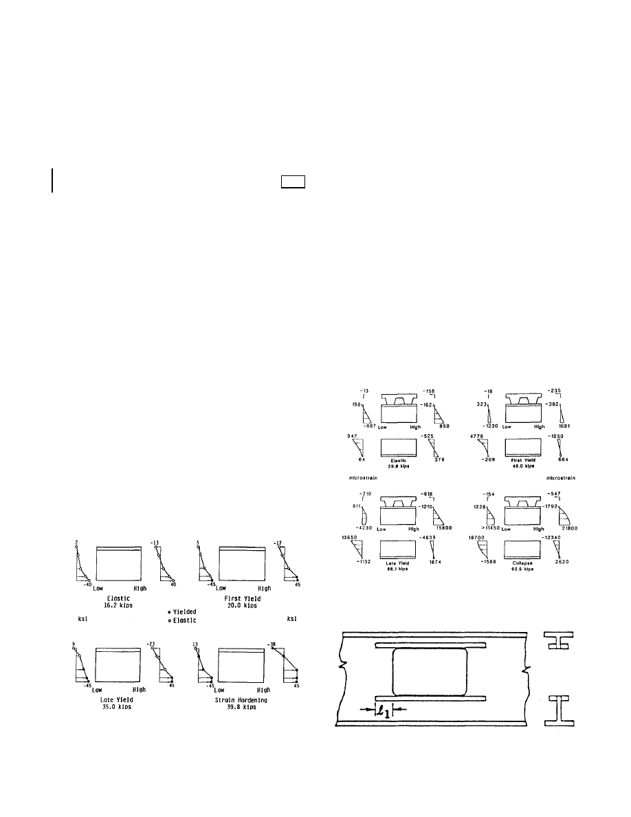
c. Shear
connectors and bridging
For composite members, shear connectors above the open-
ing and between the opening and the support strongly affect
the capacity of the section. As the capacity of the shear con-
nectors increases, the strength at the opening increases. This
increased capacity can be obtained by either increasing the
number of shear connectors or by increasing the capacity
of the individual connectors (Donahey & Darwin 1986,
Donahey & Darwin 1988). Composite sections are also sub-
ject to bridging, the separation of the slab from the steel sec-
tion. Bridging occurs primarily in beams with transverse ribs
and occurs more readily as the slab thickness increases
(Donahey & Darwin 1986, Donahey & Darwin 1988).
d. Construction
considerations
For composite sections, Redwood and Poumbouras (1983)
observed that construction loads as high as 60 percent of
member capacity do not affect the strength at web openings.
Donahey and Darwin (1986, 1988) observed that cutting
openings after the slab has been placed can result in a trans-
verse crack. This crack, however, does not appear to affect
the capacity at the opening.
e. Opening
shape
Generally speaking, round openings perform better than rec-
tangular openings of similar or somewhat smaller size (Red-
wood 1969, Redwood & Shrivastava 1980). This improved
performance is due to the reduced stress concentrations in
the region of the opening and the relatively larger web re-
gions in the tees that are available to carry shear.
f. Multiple
openings
If multiple openings are used in a single beam, strength can
be reduced if the openings are placed too closely together
Fig. 5.5. Stress diagrams for opening in steel beam—low moment-
shear ratio (Bower 1968).
(Aglan & Redwood 1974, Dougherty 1981, Redwood 1968a,
Redwood 1968b, Redwood & Shrivastava 1980). For steel
beams, if the openings are placed in close proximity, (1) a
plastic mechanism may form, which involves interaction be-
tween the openings, (2) the portion of the member between
the openings, or web post, may become unstable, or (3) the
web post may yield in shear. For composite beams, the close
proximity of web openings in composite beams may also be
detrimental due to bridging of the slab from one opening to
another.
g. Reinforcement
of openings
If the strength of a beam in the vicinity of a web opening
is not satisfactory, the capacity of the member can be in-
creased by the addition of reinforcement. As shown in Fig.
5.7, this reinforcement usually takes the form of longitudi-
nal steel bars which are welded above and below the open-
ing (U.S. Steel 1986, Redwood & Shrivastava 1980). To be
effective, the bars must extend past the corners of the open-
ing in order to ensure that the yield strength of the bars is
fully developed. These bars serve to increase both the pri-
mary and secondary flexural capacity of the member.
Fig. 5.6. Strain distributions for opening in composite beam—low
moment-shear ratio (Donahey & Darwin 1988).
Fig. 5.7. Reinforced opening.
39
Rev.
3/1/03
© 2003 by American Institute of Steel Construction, Inc. All rights reserved.
This publication or any part thereof must not be reproduced in any form without permission of the publisher.
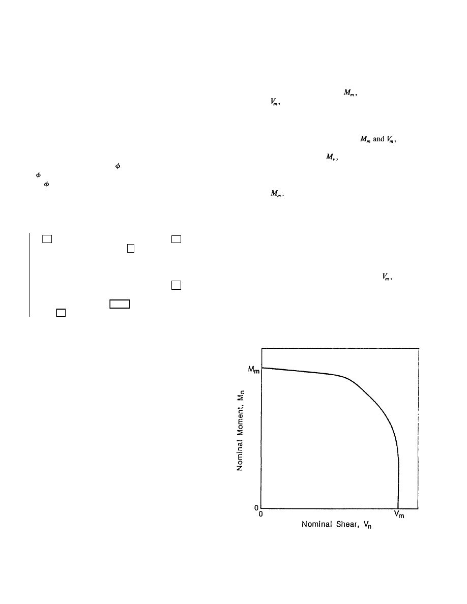
h. Load
and
resistance factors
The design of members with web openings is based on
strength criteria rather than allowable stresses because the
elastic response at web openings does not give an accurate
prediction of strength or margin of safety (Bower 1968,
Clawson & Darwin 1982, Congdon & Redwood 1970, Dona-
hey & Darwin 1988).
The load factors used by AISC (1986b) are adopted. If al-
ternate load factors are selected for the structure as a whole,
they should also be adopted for the regions of members with
web openings.
The resistance factors,
= 0.90 for steel members and
= 0.85 for composite members, coincide with the values
of used
by
AISC
(1986b) for flexure. The applicability of
these values to the strength of members at web openings was
established by comparing the strengths predicted by the de-
sign expressions in Chapter 3 (modified to account for ac-
tual member dimensions and the individual yield strengths
of the flanges, webs, and reinforcement) with the strengths
of 85 test specimens (Lucas & Darwin 1990): 29 steel beams
with unreinforced openings [19 with rectangular openings
(Bower 1968, Clawson & Darwin 1980, Congdon & Redwood
1970, Cooper et al. 1977, Redwood et al. 1978, Redwood &
McCutcheon 1968) and 10 with circular openings (Redwood
et al. 1978, Redwood & McCutcheon 1968)], 21 steel beams
with reinforced openings (Congdon & Redwood 1970, Cooper
& Snell 1972, Cooper et al. 1977, Lupien & Redwood
1978), 21 composite beams with ribbed slabs and unrein-
forced openings (Donahey & Darwin 1988, Redwood &
Poumbouras 1983, Redwood & Wong 1982), 11 composite
beams with solid slabs and unreinforced openings (Cho 1982,
Clawson & Darwin 1982, Granade 1968), and 3 composite
beams with reinforced openings (Cho 1982, Wiss et al. 1984).
Resistance factors of 0.90 and 0.85 are also satisfactory for
two other design methods discussed in this chapter (see Eqs.
5-7 and 5-29) (Lucas & Darwin 1990).
5.3 DESIGN OF MEMBERS WITH WEB
OPENINGS
The interaction between the moment and shear strengths at
an opening are generally quite weak for both steel and com-
posite sections. That is, at openings, beams can carry a large
percentage of the maximum moment capacity without a re-
duction in the shear capacity and vice versa.
The design of web openings has historically consisted of
the construction of a moment-shear interaction diagram of
the type illustrated in Fig. 5.8. Models have been developed
to generate the moment-shear diagrams point by point (Aglan
& Qaqish 1982, Clawson & Darwin 1983, Donahey & Dar-
win 1986, Poumbouras 1983, Todd & Cooper 1980, Wang
et al. 1975). However, these models were developed primarily
for research. For design it is preferable to generate the in-
teraction diagram more simply. This is done by calculating
the maximum moment capacity, the
maximum shear
capacity,
and connecting these points with a curve or
series of straight line segments. This has resulted in a num-
ber of different shapes for the interaction diagrams, as il-
lustrated in Figs. 5.8 and 5.9.
To construct a curve, the end points,
must be
determined for all models. Some other models require, in
addition, the calculation of
which represents the max-
imum moment that can be carried at the maximum shear
[Fig. 5.9(a), 5.9(b)].
Virtually all procedures agree on the maximum moment
capacity,
This represents the bending strength at an
opening subjected to zero shear. The methods differ in how
they calculate the maximum shear capacity and what curve
shape is used to complete the interaction diagram.
Models which use straight line segments for all or a por-
tion of the curve have an apparent advantage in simplicity
of construction. However, models that use a single curve,
of the type shown in Fig. 5.9(c), generally prove to be the
easiest to apply in practice.
Historically, the maximum shear capacity, has
been
calculated for specific cases, such as concentric unreinforced
openings (Redwood 1968a), eccentric unreinforced openings
(Kussman & Cooper 1976, Redwood 1968a, Redwood &
Shrivastava 1980, Wang et al. 1975), and eccentric reinforced
openings (Kussman & Cooper 1976, Redwood 1971, Redwood
Fig. 5.8. General moment-shear interaction diagram (Darwin &
Donahey 1988).
40
Rev.
3/1/03
© 2003 by American Institute of Steel Construction, Inc. All rights reserved.
This publication or any part thereof must not be reproduced in any form without permission of the publisher.
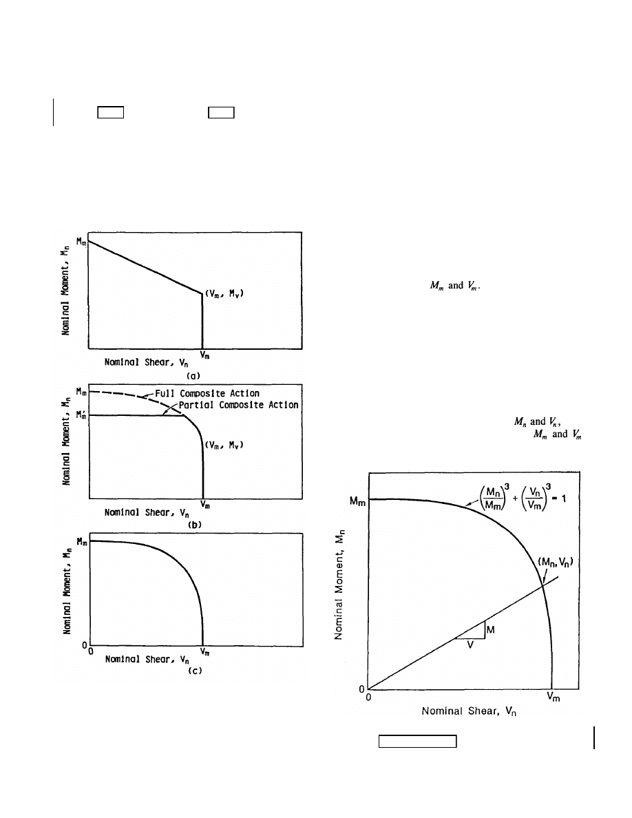
& Shrivastava 1980, Wang et al, 1975) in steel beams; and
concentric and eccentric unreinforced openings (Clawson &
Darwin 1982a, Clawson & Darwin 1982b, Darwin & Dona-
hey 1988, Redwood & Poumbouras 1984, Redwood & Wong
1982) and reinforced openings (Donoghue 1982) in composite
beams. Until recently (Lucas & Darwin 1990), there has been
little connection between shear capacity expressions for rein-
forced and unreinforced openings or for openings in steel
and composite beams. The result has been a series of special-
Fig. 5.9. Moment-shear interaction diagrams, (a) Constructed
using straight line segments, (b) constructed using
multiple junctions (Redwood & Poumbouras 1983),
(c) constructed using a single curve (Clawson &
Darwin 1980, Darwin & Donahey 1988).
ized equations for each type of construction (U.S. Steel 1986,
U.S. Steel 1984, U.S. Steel 1981). As will be demonstrated
in section 5.6, however, a single approach can generate a fam-
ily of equations which may be used to calculate the shear
capacity for openings with and without reinforcement in both
steel and composite members.
The design expressions for composite beams are limited
to positive moment regions because of a total lack of test
data for web openings in negative moment regions. The dom-
inant effect of secondary bending in regions of high shear
suggests that the concrete slab will contribute to shear
strength, even in negative moment regions. However, until
test data becomes available, opening design in these regions
should follow the procedures for steel beams.
The following sections present design equations to describe
the interaction curve, and calculate the maximum moment
and shear capacities,
5.4 MOMENT-SHEAR INTERACTION
The weak interaction between moment and shear strengths
at a web opening has been dealt with in a number of differ-
ent ways, as illustrated in Figs. 5.8 and 5.9. Darwin and Dona-
hey (1988) observed that this weak interaction can be con-
veniently represented using a cubic interaction curve to relate
the nominal bending and shear capacities,
with
the maximum moment and shear capacities,
(Fig. 5.10).
Fig. 5.10. Cubic interaction diagram (Darwin & Donahey 1988,
Donahey & Darwin 1986).
41
Rev.
3/1/03
Rev.
3/1/03
© 2003 by American Institute of Steel Construction, Inc. All rights reserved.
This publication or any part thereof must not be reproduced in any form without permission of the publisher.
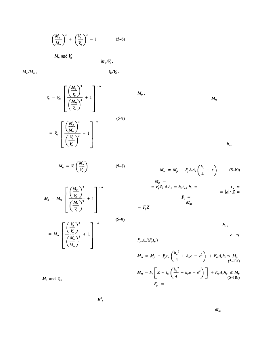
Equation 5-6 not only provides good agreement with test
results, but allows to
be
easily calculated for any
ratio of factored moment to factored shear, or
for
given ratios of factored moment to maximum moment,
and factored shear to maximum shear,
Interaction curves based on a function curve have a dis-
tinct advantage over interaction curves consisting of multi-
ple functions or line segments, since they allow the nominal
capacities, to
be
calculated
without having to
construct a unique diagram. Since the curve is generic, a sin-
gle design aid can be constructed for all material and com-
binations of reinforcement (Fig. A.1).
If the right side of Eq. 5-6 is changed to
then a fam-
ily of curves may be generated to aid in the design process,
as illustrated in Figs. 3.2 and A.1 and described in section 3.4.
5.5 EQUATIONS
FOR
MAXIMUM
MOMENT CAPACITY
The procedures that have been developed for the design of
web openings, as presented in this section, are limited to
members that meet the requirements of AISC compact sec-
tions (AISC 1986b). This limitation is necessary to prevent
instabilities in the web or compression flange of the steel
section and to allow the full limit strength to be attained at
the opening.
The design expressions for maximum moment capacity,
are based on well-established strength procedures. This
section presents the design expressions for
and explains
how the simplified versions in chapter 3 are obtained.
a. Steel
beams
Figure 5.11 illustrates stress diagrams for steel sections in
pure bending.
Unreinforced openings
For members with unreinforced openings of depth
and
eccentricity e (always taken as positive for steel sections)
[Fig. 5.11(a)], the maximum capacity at the opening is ex-
pressed as
in which
plastic bending moment of unperforated
section
depth of opening;
thickness of web; e = eccentricity of opening
plastic section modulus;
yield strength of steel.
In Chapter 3, Eq. 3-6 for
is obtained by factoring M
p
from both terms on the right side of Eq. 5-10.
Reinforced openings
For members with reinforced openings of depth
cross-
sectional area of reinforcement A
r
along both the top and
bottom edge of the opening, and eccentricity
[Fig. 5.11(b)], the maximum moment may be
expressed as
in which
yield strength of reinforcement
The development of Eq. 5-11 includes two simplifications.
First, reinforcement is assumed to be concentrated along the
top and bottom edges of the opening, and second, the thick-
ness of the reinforcement is assumed to be small. These as-
sumptions provide a conservative value for
and allow
42
© 2003 by American Institute of Steel Construction, Inc. All rights reserved.
This publication or any part thereof must not be reproduced in any form without permission of the publisher.
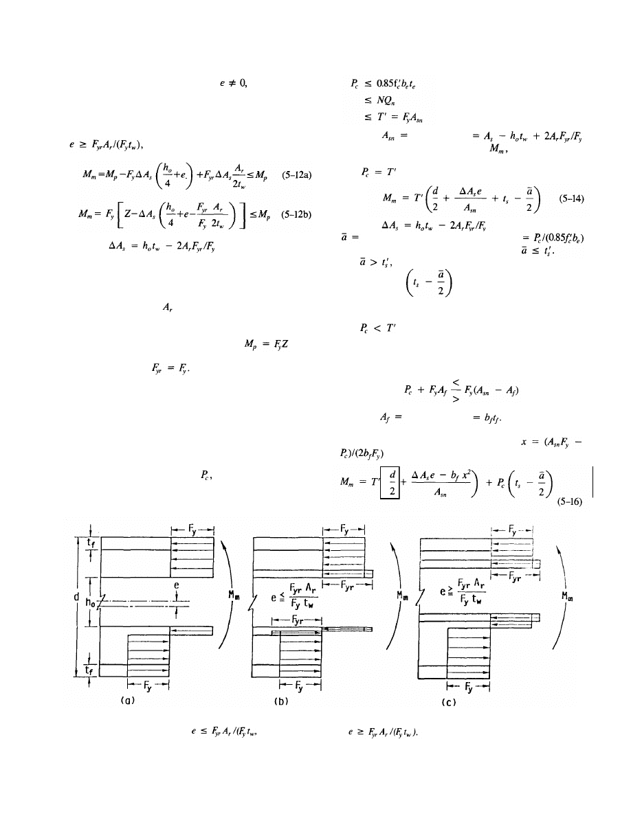
the expressions to be simplified. For
the plastic neu-
tral axis, PNA, will be located within the reinforcing bar
at the edge of the opening closest to the centroid of the origi-
nal steel section.
For members with larger eccentricities [Fig. 5.11(c)], i.e.,
the maximum moment capacity is
in which
Like Eq. 5-11, Eq. 5-12 is based on the assumptions that
the reinforcement is concentrated along the top and bottom
edges of the opening and that the thickness of the reinforce-
ment is small. In this case, however, the PNA lies in the web
of the larger tee. For
= 0, Eqs. 5-12a and b become
identically Eq. 5-10.
In Chapter 3, Eqs. 3-7 and 3-8 are obtained from Eqs.
5-11 and 5-12, respectively, by factoring from
the terms on the right-hand side of the equations and mak-
ing the substitution
The moment capacity of reinforced openings is limited to
the plastic bending capacity of the unperforated section (Red-
wood & Shrivastava 1980, Lucas and Darwin 1990).
b. Composite
beams
Figure 5.12 illustrates stress diagrams for composite sections
in pure bending. For a given beam and opening configura-
tion, the force in the concrete,
is limited to the lower
of the concrete compressive strength, the shear connector
capacity, or the yield strength of the net steel section.
(5-13a)
(5-13b)
(5-13c)
in which
net steel area
The maximum moment capacity, depends
on
which
of the inequalities in Eq. 5-13 governs.
If [Eq.
5-13c and Fig. 5.12(a)],
in which
depth of concrete compression block
for solid slabs and ribbed slabs for which
If
as it can be for ribbed slabs with longitudinal
ribs, the term in
Eq.
5-14
must
be
replaced
with the appropriate expression for the distance between the
top of the steel flange and the centroid of the concrete force.
If
(Eq. 5-13a or 5-13b), a portion of the steel
section is in compression. The plastic neutral axis, PNA, may
be in either the flange or the web of the top tee, based on
the inequality:
(5-15)
in which
the flange area
If the left side of Eq. 5-15 exceeds the right side, the PNA
is in the flange [Fig. 5.12b] at a distance
from the top of the flange. In this case,
43
Fig. 5.11. Steel sections in pure bending, (a) Unreinforced opening, (b) reinforced opening,
(c) reinforced opening,
Rev.
3/1/03
© 2003 by American Institute of Steel Construction, Inc. All rights reserved.
This publication or any part thereof must not be reproduced in any form without permission of the publisher.
(
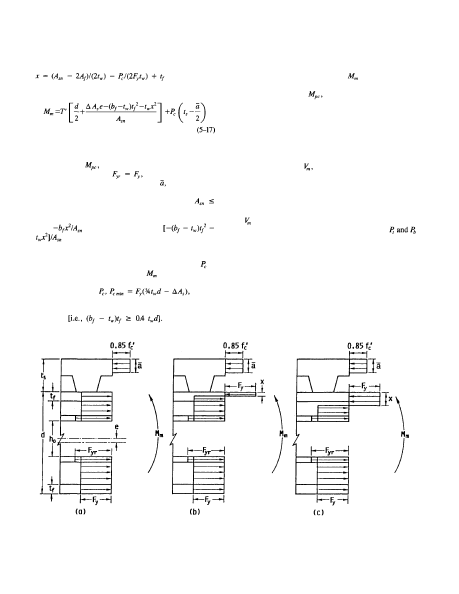
flange-to-web area ratio criterion is conservative, and the ac-
curacy of Eq. 3-10 improves as this ratio increases.
For safety in design, the value of
in Eqs. 5-14, 5-16
and 5-17 should be limited to the nominal capacity of the
unperforated section,
when reinforcement is used
(Lucas & Darwin 1990).
5.6 EQUATIONS
FOR
MAXIMUM SHEAR
CAPACITY
The procedure used to calculate the maximum shear capac-
ity at a web opening,
is one of the key aspects that dis-
tinguishes one design method from another. The procedures
presented here are an adaptation (Lucas & Darwin 1990) of
techniques developed by Darwin and Donahey (1988, 1986)
that have proven to give accurate results for a wide range
of beam configurations.
is calculated by considering the load condition in
which the axial forces at the top and bottom tees,
= 0 (Fig. 5.13). This load condition represents the "pure"
shear (M = 0) for steel sections and is a close approxima-
tion of pure shear for composite sections. This load case does
not precisely represent pure shear for composite beams be-
cause, while the secondary bending moments at each end
of the bottom tee are equal, the secondary bending moments
at each end of the top tee are not equal because of the un-
equal contributions of the concrete at each end. Thus, the
moment at the center line of the opening has a small but
finite value for composite sections.
Fig. 5.12. Composite sections in pure bending, (a) Neutral axis above top of flange, (b) neutral
axis in flange, (c) neutral axis in web.
44
If the right side of Eq. 5-15 is greater than the left side,
the neutral axis is in the web [Fig. 5.12(c)] at a distance
from the top of
the flange. In this case,
In Chapter 3, Eq. 3-9 is obtained from Eq. 5-14 by fac-
toring the nominal capacity of the composite section with-
out an opening,
from the terms on the right hand side
of the equation, setting
and assuming that the
depth of the concrete compression block,
does not change
significantly due to the presence of the opening and the rein-
forcement. This approximation is conservative for
A
s
and is usually accurate within a few percent. Equation
3-10 is obtained from Eqs. 5-16 and 5-17 assuming that the
term
in Eq. 5-16 and the term
in Eq. 5-17 are small compared to d/2. Equation
3-10 is exact if the PNA is above the top of the flange and
always realistic if the PNA is in the flange. However, it may
not always be realistic if the PNA is in the web, if
is
small. Since the approximation for
in Eq. 3-10 is ex-
act or unconservative, a limitation on its application is nec-
essary. The limit on
ensures
that the neglected terms are less than 0.04(d/2) for members
in which the flange area equals or exceeds 40 percent of the
web area
The 40 percent
© 2003 by American Institute of Steel Construction, Inc. All rights reserved.
This publication or any part thereof must not be reproduced in any form without permission of the publisher.
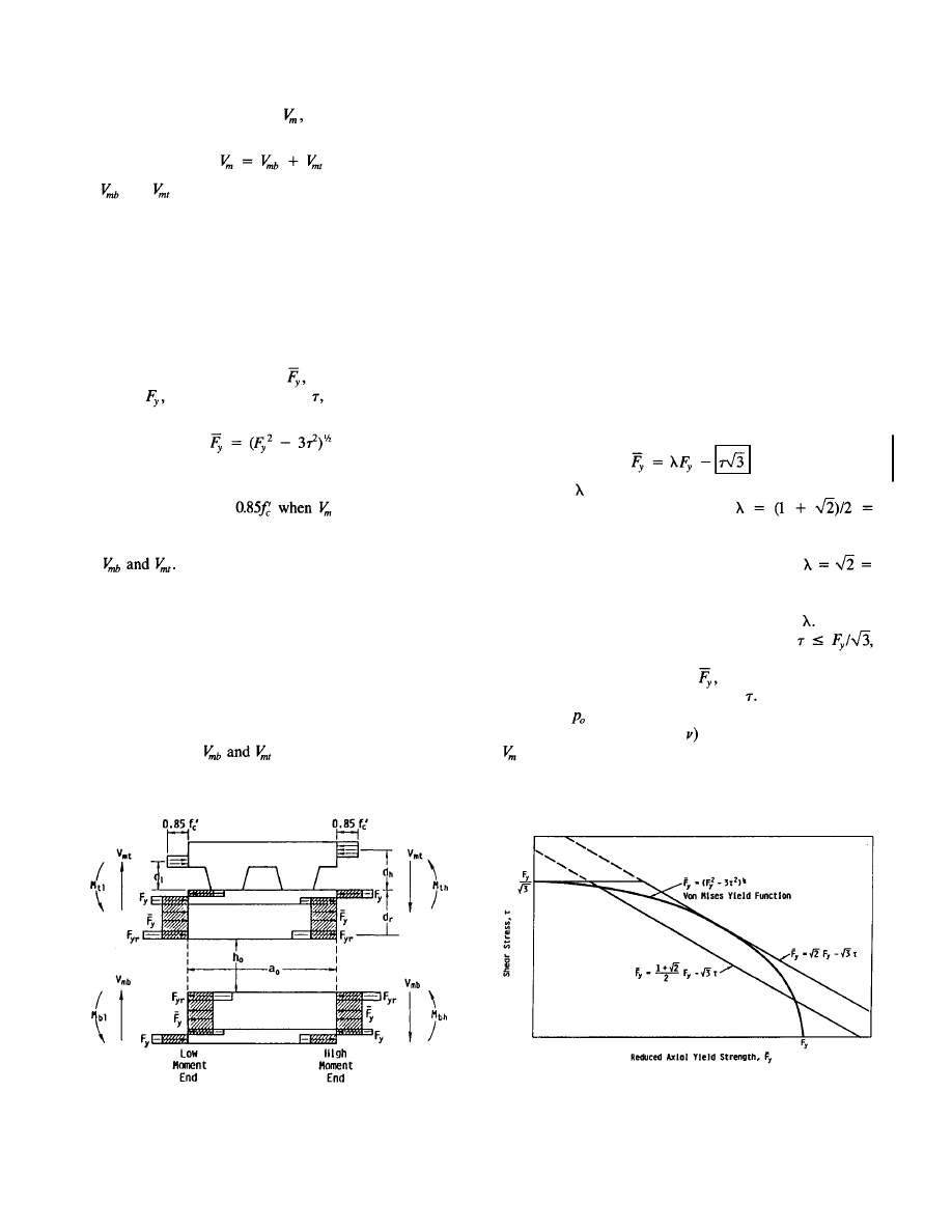
The capacity at the opening,
is obtained by summing
the individual capacities of the bottom and top tees.
(5-18)
and are
calculated using the moment equilibrium
equations for the tees, Eq. 5-3 and 5-4, and appropriate
representations for the stresses in the steel, and if present,
the concrete and opening reinforcement. Since the top and
bottom tees are subjected to the combined effects of shear
and secondary bending, interaction between shear and axial
stresses must be considered in order to obtain an accurate
representation of strength. The greatest portion of the shear
is carried by the steel web.
The interaction between shear and normal stress results
in a reduced axial strength, for
a
given material
strength, and
web
shear stress,
which can be repre-
sented using the von Mises yield criterion.
(5-19)
The interaction between shear and axial stress is not con-
sidered for the concrete. However, the axial stress in the con-
crete is assumed to be
is obtained.
The stress distributions shown in Fig. 5.13, combined with
Eqs. 5-3 and 5-4 and Eq. 5-19, yield third order equations
in These
equations must be solved by iteration,
since a closed-form solution cannot be obtained (Clawson
& Darwin 1980).
For practical design, however, closed-form solutions are
desirable. Closed-form solutions require one or more addi-
tional simplifying assumptions, which may include a sim-
plified version of the von Mises yield criteria (Eq. 5-19),
limiting neutral axis locations in the steel tees to specified
locations, or ignoring local equilibrium within the tees.
As demonstrated by Darwin & Donahey (1988), the form
of the solution for
depends on the particular as-
sumptions selected. The expressions in Chapter 3 use a sim-
plified version of the von Mises criterion and ignore some
aspects of local equilibrium within the tees. Other solutions
may be obtained by using fewer assumptions, such as the
simplified version of the von Mises criterion only or ignor-
ing local equilibrium within the tees only. The equations used
in Chapter 3 will be derived first, followed by more com-
plex expressions.
a. General
equation
A general expression for the maximum shear capacity of a
tee is obtained by considering the most complex configura-
tion, that is, the composite beam with a reinforced opening.
Expressions for less complex configurations are then obtained
by simply removing the terms in the equation correspond-
ing to the concrete and/or the reinforcement.
The von Mises yield criterion, Eq. 5-19, is simplified us-
ing a linear approximation.
(5-20)
The term can be selected to provide the best fit with data.
Darwin and Donahey (1988) used
1.207..., for which Eq. 5-20 becomes the linear best uni-
form approximation of the von Mises criterion. More recent
research (Lucas & Darwin 1990) indicates that
1.414... gives a better match between test results and
predicted strengths. Figure 5.14 compares the von Mises
criterion with Eq. 5-20 for these two values of As illus-
trated in Fig. 5.14, a maximum shear cutoff,
based on the von Mises criterion, is applied. Figure 5.14 also
shows that the axial stress,
may be greatly over-
estimated for low values of shear stress,
However, the limi-
tations on
(section 3.7a2) force at least one tee to be
stocky enough (low value of
that the calculated value of
is conservative. In fact, comparisons with tests of steel
beams show that the predicted strengths are most conserva-
Fig. 5.13. Axial stress distributions for opening at maximum shear.
Fig. 5.14. Yield functions for combined shear and axial stress.
45
Rev.
3/1/03
© 2003 by American Institute of Steel Construction, Inc. All rights reserved.
This publication or any part thereof must not be reproduced in any form without permission of the publisher.
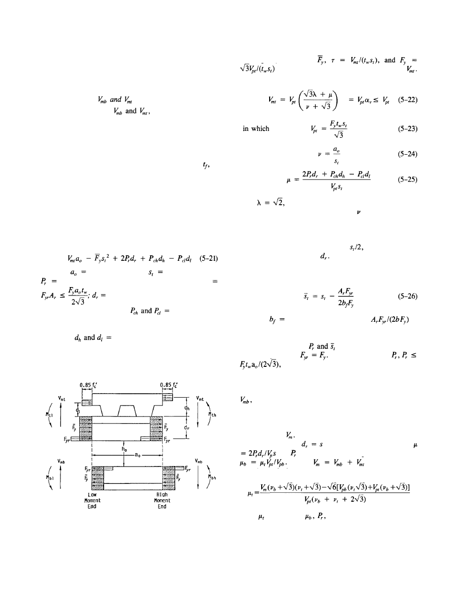
live for openings with low moment-shear ratios (Lucas &
Darwin 1990), cases which are most sensitive to the approx-
imation in Eq. 5-20.
Equation 3-13 for
To obtain Eq. 3-13 for
the stress distribution
shown in Fig. 5.15 is used in conjunction with Eqs. 5-3 and
5-4. This distribution represents a major simplification of
the distribution shown in Fig. 5.13, since the flange stresses
are not used to calculate the secondary moments. This ap-
proximation can be justified, because the plastic neutral axis
usually lies in the flange and the flange thickness,
is
small relative to the stub depth. Thus, the contribution of
the flanges to the secondary moments is small. Using this
approximation, the normal and shear stresses in the web are
assumed to be uniform through the stub depth, ignoring lo-
cal equilibrium.
The top tee in Fig. 5.15 is used to develop an equation for
the maximum shear capacity of a tee in general form. The
equilibrium equation for moments taken about the top of the
flange at the low moment end of the opening is
in which
length of opening; depth
of
top
tee;
force in reinforcement along edge of opening
distance from outside edge of flange
to centroid of reinforcement;
concrete forces
at high and low moment ends of opening, respectively [For
top tee in composite sections only. See Eqs. 3-15a through
3-16]; and
distances from outside edge of top
flange to centroid of concrete force at high and low moment
ends of opening, respectively. [For top tee in composite sec-
tions only. See Eqs. 3-17 through 3-18b.]
Fig. 5.15. Simplified axial stress distributions for opening at
maximum shear.
Using Eq. 5-20 for
in Eq. 5-21 results in a linear equation in
The solution of the equation takes the following simple form:
With Eq.
5-22 becomes Eq. 3-13.
One modification to the definition of in Eq. 5-24 is nec-
essary for reinforced openings. When reinforcement is added,
the PNA in the flange of the steel section (Fig. 5.13) will
move. This movement effectively reduces the moment arm
of the normal stresses in the web,
and the moment
arm of the reinforcement
The movement of the PNA
can be reasonably accounted for by modifying the s, term
in Eq. (5-24) only (Lucas & Darwin 1990).
in which
width of flange. The term
in
Eq. 5-26 approximates the movement of the PNA due to
the addition of the reinforcement.
The expressions for
in Chapter 3 are based on
the assumption that
A limit is placed on
based on the shear strength of the web. This
requirement conservatively replaces the shear rupture
strength requirement of section J4 of AISC (1986b).
An expression for the shear capacity of the bottom tee,
is obtained by suitable substitutions in Eqs. 5-22
through 5-26.
A direct calculation can be made to estimate the reinforce-
ment needed by steel beams to provide a desired maximum
shear strength, The
calculation is based on the simplify-
ing assumption that
in Eq. 3-14 and 5-25. Since
and
is the same for the top and bottom tees,
Taking and
making ap-
propriate substitutions,
Once is
obtained, and A
r
can be calculated.
An equivalent expression cannot be easily obtained for
composite beams. Selection of a trial value of reinforcement,
46
© 2003 by American Institute of Steel Construction, Inc. All rights reserved.
This publication or any part thereof must not be reproduced in any form without permission of the publisher.
however, provides a straightforward solution for both steel
and composite beams, as illustrated in Examples 2 and 4 in
Chapter 3.
Alternate equations for
If the full von Mises criterion (Eq. 5-19) is used, instead
of the linear approximation (Eq. 5-20), to represent in
Eq. 5-21, a quadratic equation is obtained for
The so-
lution of that equation takes a somewhat more complex form
than Eq. 5-21.
(5-27)
in which
are as previously defined. For non-
composite tees without reinforcement, Eq. 5-27 takes a sim-
pler form.
(5-28)
Equations 5-27 and 5-28 are identical with those used by
Redwood and Poumbouras (1984) and by Darwin and Dona-
hey (1988) in their "Solution II." These equations completely
satisfy the von Mises criterion, but, perhaps surprisingly, do
not provide a closer match with experimental data than Eq.
5-22 (Lucas & Darwin 1990).
To obtain a better match with experimental results requires
another approach (Darwin & Donahey 1988, Lucas & Dar-
win 1990). This approach uses the linear approximation for
the von Mises criterion (Eq. 5-19) to control the interaction
between shear and normal stresses within the web of the steel
tee, but uses a stress distribution based on the full cross-
section of the steel tee (Fig. 5.13) to develop the secondary
moment equilibrium equation (Eq. 5-4). The PNA is as-
sumed to fall in the flange of the steel tee; its precise loca-
tion is accounted for in the solution for
is expressed as follows:
Equation 5-29 is clearly more complex than Eqs. 5-22
and 5-27 and is best suited for use with a programmable cal-
culator or computer. It has the advantages that it accounts
for the actual steel section and does not require a separate
calculation for when reinforcement is used. With
Eq. 5-29 produces a closer match with the experimental data
than the other two options (Lucas & Darwin 1990). How-
ever, since the flange is included in the calculations, Eq. 5-29
cannot be used to produce a general design aid.
Expressions for tees without concrete and/or opening rein-
forcement can be obtained from Eqs. 5-29 by setting
and to
zero,
as
required.
b. Composite beams
As explained in Chapter 3, a number of additional expres-
sions are required to calculate the shear capacity of the top
tee in composite beams.
The forces in the concrete at the high and low moment
ends of the opening,
and the distances to these
forces from the top of the flange of the steel section, and
d
h
are calculated using Eqs. 3-15a through 3-18b. is
limited by the force in the concrete, based on an average
stress of
the stud capacity between the
high moment end of the opening and the support
and
the tensile capacity of the top tee steel section, The
third limitation
was not originally used in conjunc-
tion with Eqs. 5-22 and 5-27, because it was felt to be in-
consistent with a model (Fig. 5-15) that ignored the flange
of the steel tee (Darwin & Donahey 1988, Donahey & Dar-
win 1986). Lucas and Darwin (1990), however, have shown
that generally improved solutions are obtained when all these
limitations are used in conjunction with Eqs. 5-22 and 5-27,
as well as Eq. 5-29 which considers the flange.
The number of studs, N, used for the calculation of
includes the studs between the high moment end of the open-
ing and the support, not the point of zero moment. This
change from normal practice takes into account the large
amount of slip that occurs between the slab and the steel
section at openings, which tends to mobilize stud capacity,
even studs in negative moment regions (Darwin & Donahey
1988, Donahey & Darwin 1986, Donahey & Darwin 1988).
To use the more conservative approach will greatly under-
estimate the shear capacity of openings placed at a point of
contraflexure (Donahey & Darwin 1986).
47
in which
Rev.
3/1/03
)
Rev.
3/1/03
© 2003 by American Institute of Steel Construction, Inc. All rights reserved.
This publication or any part thereof must not be reproduced in any form without permission of the publisher.
l
The difference between
(Eq. 3-16) is equal to
the shear connector capacity over the opening,
Equations 5-22, 5-27, and 5-29 are based on the assump-
tion that all of the shear carried by a tee is carried by the
steel web. This assumption yields consistent results for steel
tees, but may be overconservative for top tees in composite
beams, since the concrete slab may also carry shear. If
in these expressions exceeds
the web is fully yielded in
shear .
Equilibrium requires that
is limited to
the axial strength of the flange and the reinforcement in the
top tee, as given by Eq. 3-20,
in which
thickness of flange. This limit on
replaces
Eq. 3-15c.
Resolving Eq. 5-21 yields
Equation 5-30b is equivalent to Eq. 3-19. Since is
correctly defined by Eq. 5-30a, in
Eq.
5-30b
is calculated based on s for reinforced openings.
If the flange of the top tee is included in the equilibrium
equation once the
solution
for
yields
The value of
calculated with Eq. 5-31 slightly exceeds
the value obtained with Eq. 5-30. Equation 5-31 has been
used in conjunction with Eq. 5-29, while Eq. 5-30 has been
used with Eqs. 5-22 and 5-27 (Cho & Redwood 1986, Darwin
& Donahey 1988, Donahey & Darwin 1986, AISC 1986b).
An upper limit is placed on
in Eq. 3-21, based on the
maximum combined capacity of the steel web and the con-
crete slab in pure shear.
The contribution of the concrete to the maximum shear
capacity of the top tee in Eq. 3-21, 0.11
was origi-
nally estimated for solid slabs, based on the shear behavior
of reinforced concrete beams and slabs (Clawson & Darwin
1980, Clawson & Darwin 1983), and later modified for
ribbed slabs (Darwin & Donahey 1988, Donahey & Darwin
1986). Equation 3-21 generally governs only
for
beams
with short openings, usually
c. Design
aids
The design aids presented in Appendix A, Figs. A.2 and A.3,
represent as
a
function of
or for
values
of
ranging from 0 to 23.
The upper limit of
in Fig. A.3 is se-
lected for convenience and clarity of the diagram. Only two
beams in all of the tests exceeded this value (Lucas & Dar-
win 1990). For most practical cases,
will be less than 2.
The upper limit of
coincides with the maximum
value used in tests of members subjected to shear (Lucas &
Darwin 1990).
5.7 GUIDELINES
FOR
PROPORTIONING
AND DETAILING BEAMS WITH WEB
OPENINGS
The guidelines presented in section 3.7 are based on both
theoretical considerations and experimental observations.
Many of the guidelines were originally developed for non-
composite beams (Redwood & Shrivastava 1980, ASCE 1973)
and are adopted as appropriate for composite members. The
guidelines are meant to help ensure that the limit states
predicted by the design equations are obtained. For this rea-
son, steel sections should meet the AISC requirements for
compact sections (AISC 1986b). Yield strength, is
limited to 65 ksi since plastic design is the basis for the de-
sign expressions. The other provisions of the AISC LRFD
Specifications (AISC 1986b) should apply to these members
as well.
a. Stability
considerations
1. Local buckling of compression flange or
reinforcement
To prevent local buckling of the compression flange or rein-
forcement at an opening, the AISC (1986b) criteria for com-
pact sections is applied to the reinforcement as well as the
steel section (Eq. 3-22).
2. Web
buckling
The criteria to prevent web buckling are based on the work
of Redwood and Uenoya (1979) in which they developed con-
servative criteria based on the opening size and shape and
the slenderness of the web of the member. The recommen-
dations are based on both experimental (Redwood et al. 1978)
and analytical work (Redwood & Uenoya 1979, Uenoya &
Redwood 1978). The experimental work included openings
with depths or diameters ranging from 0.34d to 0.63d and
opening length-to-depth ratios of 1 and 2. The analyses
covered openings with depths and
opening length-
to-depth ratios ranging from 1 to 2.
Their recommendations are adopted in whole for steel
members and relaxed slightly for composite sections to ac-
count for the portion of the shear carried by the concrete
slab, The
higher limit on the opening parameter, of
6.0 for composite sections versus 5.6 for steel sections coin-
48
© 2003 by American Institute of Steel Construction, Inc. All rights reserved.
This publication or any part thereof must not be reproduced in any form without permission of the publisher.
cides with successful tests (Donahey & Darwin 1988). Fail-
ure in composite sections is normally governed by failure
of the concrete slab, and adequate strength has been obtained
even when local buckling has been observed (Clawson & Dar-
win 1980, Clawson & Darwin 1982, Donahey & Darwin
1986). As discussed in section 5.6 (after Eq. 5-20), the limits
on also
serve to ensure that the design equations provide
conservative predictions for member shear strength, even if
web buckling is not a factor.
Limits on
based on the web width-thickness ratio are
used for both steel and composite sections. Somewhat more
lenient criteria are applied to the composite sections. How-
ever, no detailed theoretical analyses have been made. The
guidelines limiting the maximum values of
can be quite
conservative for sections with web width-thickness ratios be-
low the maximum limits. Redwood & Uenoya (1979) pro-
vide guidance for members which lie outside the limits of
this section.
3. Buckling of tee-shaped compression zone
For noncomposite members, a check must be made to en-
sure that buckling of the tee-shaped compression zone above
or below an opening does not occur. This is of concern
primarily for large openings in regions of high moment (Red-
wood & Shrivastava 1980). This need not be considered for
composite members subject to positive bending.
4. Lateral
buckling
The guidelines for openings in members subject to lateral
buckling closely follow the recommendations of Redwood
and Shrivastava (1980). They point out that openings have
little effect on the lateral stability of W-shaped sections. How-
ever, design expressions have not been formulated to pre-
dict the inelastic lateral buckling capacity for a member with
an opening, and to be safe, member strength should be
governed by a point remote from the opening (Redwood &
Shrivastava 1980).
Equation 3-26 is an extension of recommendations made
by Redwood & Shrivastava (1980) and ASCE (1973) for use
with the lateral buckling provisions of design specifications
(AISC 1986b). Redwood and Shrivastava recommend the ap-
plication of Eq. 3-26 only if the value of this expression is
less than 0.90.
The increased load on the lateral bracing for unsymmetri-
cally reinforced members is also recommended by Lupien
and Redwood (1978).
b. Other
considerations
1. Opening and tee dimensions
Opening dimensions are largely controlled by the limitations
on given
in
section 3.7a2. The limitations
placed on the opening and tee dimensions in section 3.7bl
are based on practical considerations. Opening depths in ex-
cess of 70 percent of the section depth are unrealistically
large. The minimum depths of the tees are based on the need
to transfer some load over the opening and a lack of test data
for shallower tees. The limit of 12 on the aspect ratio of the
tees
is based on a lack of data for members with
greater aspect ratios.
2. Corner
radii
The limitations on the corner radii of the opening are based
on research by Frost and Leffler (1971), which indicates that
corner radii meeting these requirements will not adversely
affect the fatigue capacity of a member. In spite of this point,
openings are not recommended for members that will be sub-
jected to significant high cycle-low stress or low cycle-high
stress fatigue loading.
3. Concentrated
loads
Concentrated loads are not allowed over the opening because
the design expressions are based on a constant value of shear
through the openings and do not account for the local bend-
ing and shear that would be caused by a load on the top tee.
A uniform load (standard roof or floor loads) will not cause
a significant deviation from the behavior predicted by the
equations. If a concentrated load must be placed over the
opening, additional analyses are required to evaluate the re-
sponse of the top tee and determine its effect on the strength
of the member at the opening. The limitations on the loca-
tions of concentrated loads near openings to prevent web
crippling are based on the criteria offered by Redwood &
Shrivastava (1980). The requirements represent an extension
of the criteria suggested by Redwood & Shrivastava (1980).
These criteria are applied to composite and noncomposite
members with and without reinforcement, although only
limited data exists except for unreinforced openings in steel
sections (Cato 1964). The requirement that openings be
placed no closer than a distance d to a support is to limit
the horizontal shear stress that must be transferred by the
web between the opening and the support.
4. Circular
openings
The criteria for converting circular openings to equivalent
rectangular openings for application with the design expres-
sions are adopted from Redwood & Shrivastava (1980), which
is based on an investigation by Redwood (1969) into the lo-
cation of plastic hinges relative to the center line of open-
ings in steel members. These conversions are adopted for
composite beams as well. The use of
for both
shear and bending in members with reinforced web open-
ings is due to the fact that the reinforcement is adjacent to
the opening. Treating the reinforcement as if it were adja-
cent to a shallower opening would provide an unconserva-
tive value for
49
© 2003 by American Institute of Steel Construction, Inc. All rights reserved.
This publication or any part thereof must not be reproduced in any form without permission of the publisher.
5. Reinforcement
The requirements for reinforcement are designed to ensure
that adequate strength is provided in the regions at the ends
of the opening and that the reinforcement is adequately at-
tached to develop the required strength. Equation 3-31 re-
quires the weld to develop a strength of
within
the length of the opening. The factor 2 is used because the
reinforcement is in tension at one end of the opening and
in compression at the other end when the tee is subjected
to shear (Figs. 5.13 and 5.15). Within the extensions, rein-
forcement must be anchored to provide the full yield strength
of the bars, since the expressions for
are based on this
assumption. This requires (1) an extension length
based on the shear strength of the web and (2)
a weld capacity of
(see Eq. 3-32). The limit on
allows a single size fillet weld to be used on one side
of the bar within the length of the opening and on both sides
of the bar in the extensions.
The terms
in Eq. 3-31 and
in Eq. 3-32 are mul-
tiplied by
(0.90 for steel beams and 0.85 for composite
beams) to convert these forces into equivalent factored loads.
The weld is then designed to resist the factored load,
with a value of
0.75 (AISC 1986b). The result is a de-
sign which is consistent with AISC (1986b).
The criteria for placing the reinforcement on one side of
the web are based on the results of research by Lupien and
Redwood (1978). The criteria are designed to limit reduc-
tions in strength caused by out of plane deflections caused
by eccentric loading of the reinforcement. The limitations
on the area of the reinforcement, in
Eq.
3-33 and as-
pect ratio of the opening, in
Eq.
3-34 represent the
extreme values tested by Lupien and Redwood. The limita-
tion on the tee slenderness,
in Eq. 3-35 is primarily
empirical. The limitation on
in Eq. 3-36 restricts
the use of unsymmetrical reinforcement to regions subject
to some shear. For regions subjected to pure bending or very
low shear, the out of plane deflections of the web can be
severe. Under shear, the lateral deformation mode caused
by the unsymmetrical reinforcement changes to allow a
greater capacity to be developed. Additional guidance is
given by Lupien & Redwood (1978) for the use of unsym-
metrical reinforcement in regions of pure bending or very
low shear.
The criteria are adopted for composite as well as steel
beams.
6. Spacing
of
openings
Equations 3-37a through 3-38b are designed to ensure that
openings are spaced far enough apart so that design expres-
sions for individual openings may be used (Redwood &
Shrivastava 1980). Specifically, the criteria are meant to en-
sure that a plastic mechanism involving interaction between
openings will not develop, instability of the web posts be-
tween openings will not occur, and web posts between open-
ings will not yield in shear.
The additional requirements for composite members in
Eqs. 3-39a and b are based on observations by Donahey and
Darwin (1986, 1988) of slab bridging in members with sin-
gle openings. The expressions are designed to limit the poten-
tial problem of slab bridging between adjacent openings, al-
though no composite beams with multiple openings have been
tested.
c. Additional
criteria
for
composite beams
1. Slab
reinforcement
Slabs tend to crack both transversely and longitudinally in
the vicinity of web openings. Additional slab reinforcement
is needed in the vicinity of the openings to limit the crack
widths and improve the post-crack strength of the slab. The
recommendations are based on observations by Donahey and
Darwin (1986, 1988).
2. Shear
connectors
Donahey and Darwin (1986, 1988) observed significant bridg-
ing (lifting of the slab from the steel section) from the low
moment end of the opening past the high moment end of
the opening in the direction of increasing moment. The studs
in the direction of increasing moment are designed to help
limit bridging, although the studs do not enter directly into
the calculation of member strength at the opening. The mini-
mum of two studs per foot is applied to the total number
of studs. If this criterion is already satisfied by normal stud
requirements, additional studs are not needed.
3. Construction
loads
This requirement recognizes that a composite beam with ade-
quate strength at a web opening may not provide adequate
capacity during construction, when it must perform as a non-
composite member.
5.8 ALLOWABLE
STRESS DESIGN
The design of web openings in beams that are proportioned
using Allowable Stress Design must be based on strength be-
cause the load at which yielding begins at web openings is
not a uniform measure of strength. Conservatively and for
convenience, a single load factor, 1.7, is used for dead and
live loads and a single factor, 1.00, is used for both steel
and composite construction.
50
© 2003 by American Institute of Steel Construction, Inc. All rights reserved.
This publication or any part thereof must not be reproduced in any form without permission of the publisher.
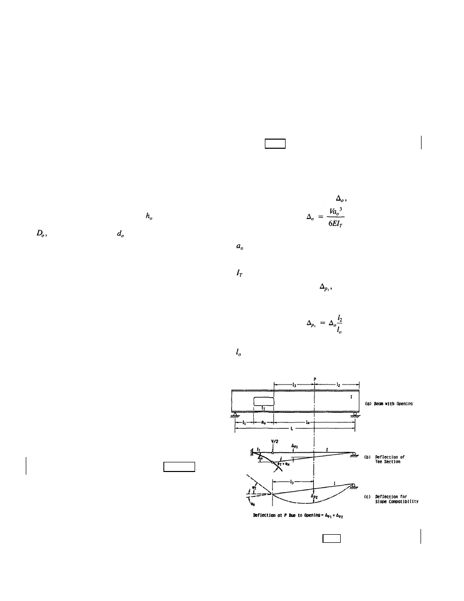
Chapter 6
DEFLECTIONS
6.1 GENERAL
A web opening may have a significant effect on the deflec-
tions of a beam. In most cases, however, the influence of
a single web opening is small.
The added deflection caused by a web opening depends
on its size, shape, and location. Circular openings have less
effect on deflection than rectangular openings. The larger
the opening and the closer the opening is to a support, the
greater will be the increase in deflection caused by the open-
ing. The greatest deflection through the opening itself will
occur when the opening is located in a region of high shear.
Rectangular openings with a depth,
, up to 50 percent of
the beam depth, d, and circular openings with a diameter,
up to 60 percent of ,
cause
very little additional
deflection (Donahey 1987, Redwood 1983). Multiple open-
ings can produce a pronounced increase in deflection.
As a general rule, the increase in deflection caused by a
single large rectangular web opening is of the same order
of magnitude as the deflection caused by shear in the same
beam without an opening. Like shear deflection, the shorter
the beam, the greater the deflection caused by the opening
relative to the deflection caused by flexure.
6.2 DESIGN
APPROACHES
Web openings increase deflection by lowering the moment
of inertia at the opening, eliminating strain compatibility be-
tween the material in the top and bottom tees, and reducing
the total amount of material available to transfer shear (Dona-
hey 1987, Donahey & Darwin 1986). The reduction in gross
moment of inertia increases the curvature at openings, while
the elimination of strain capability and reduction in mate-
rial to transfer shear increase the differential, or Vierendeel,
deflection across the opening. The Vierendeel deformation
is usually of greater concern than is the local increase in
curvature.
A number of procedures have been developed to calculate
deflections for flexural members with web openings. Three
procedures specifically address steel beams (Dougherty 1980,
McCormick 1972a, ASCE 1973), and one method covers
composite members (Donahey 1987, Donahey & Darwin
1986). The first three procedures calculate deflections due
to the web opening that are added to the deflection of the
beam without an opening. The method developed for com-
posite members, which can also be used for steel beams,
calculates total deflections of members with web openings.
Three of these methods will now be briefly described.
6.3 APPROXIMATE
PROCEDURE
The Subcommittee on Beams with Web Openings of the Task
Committee on Flexural Members of the Structural Division
of ASCE (1971) developed an approximate procedure that
represents the portion of the beam from the low moment end
of the opening to the far end of the beam as a hinged, propped
cantilever (Fig. 6.1). The method was developed for beams
with concentric openings. The shear at the opening, V, is
evenly distributed between the top and bottom tees. The
deflection through the opening, is
= length of opening
E = modulus of elasticity of steel
= moment of inertia of tee
The additional deflection,
at any point between the
high moment end of the opening and the support caused by
the opening (Fig. 6.1) is expressed as
(6-2)
in which
= distance from high moment end of opening to adja-
cent support (Fig. 6.1)
Fig. 6.1. Deflections due to web opening—approximate
approach (ASCE 1971).
51
in which
(6-1)
Rev.
3/1/03
Rev.
3/1/03
Rev.
3/1/03
© 2003 by American Institute of Steel Construction, Inc. All rights reserved.
This publication or any part thereof must not be reproduced in any form without permission of the publisher.
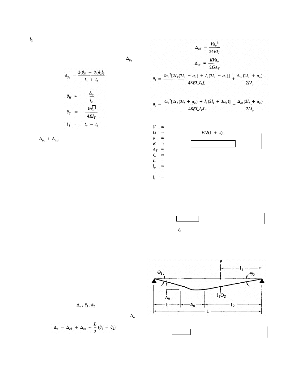
= distance from support to point at which deflection is
calculated (Fig 6.1)
To enforce slope continuity at the high moment end of the
opening, an additional component of deflection,
is
obtained.
The sum of the displacements calculated in Eqs. 6-2 and
6-3, is
added to the deflection obtained for the
beam without an opening. The procedure does not consider
the deflection from the low moment end of the opening to
the adjacent support, slope compatibility at the low moment
end of the opening, axial deformation of the tees, or shear
deformation in the beam or through the opening. The sub-
committee reported that the procedure is conservative.
McCormick (1972b) pointed out that the subcommittee pro-
cedure is conservative because of a lack of consideration of
compatibility between the axial deformation of the tees and
the rest of the beam. He proposed an alternate procedure
in which points of contraflexure are assumed at the center
line of the opening (McCormick 1972a). Bending and shear
deformation of the tees are included but compatibility at the
ends of an opening is not enforced. McCormick made no
comparison with experimental results.
6.4 IMPROVED
PROCEDURE
shear at opening center line
shear modulus =
Poisson's ratio
shape factor (Knostman et al. 1977)
area of tee
moment of inertia of perforated beam
length of beam
distance from high moment end of opening to adja-
cent support (Fig. 6.2)
distance from low moment end of opening to adja-
cent support (Fig. 6.2)
The reader is referred to Dogherty (1980) for the case of ec-
centric openings.
The procedure can, in principle, be used to calculate
deflection due to an opening in a composite beam as well
as a steel beam. In that case, based on the work of Donahey
and Darwin (1986, 1987) described in the next section, the
moment of inertia of the top tee should be based on the steel
tee only, but
should be based on the composite section
at the opening.
Dougherty (1980) developed a method in which the deflec-
tion due to Vierendeel action at a web opening is obtained
(Fig. 6.2). The calculations take into account deformations
due to both secondary bending and shear in the tee sections
above and below the opening and slope compatibility at the
ends of the opening. The increased curvature under primary
bending due to the locally reduced moment of inertia at the
opening is not included. Shear is assigned to the tees in
proportion to their relative stiffnesses, which take into ac-
count both flexural and shear deformation.
As shown in Fig. 6.2,
fully define the deflec-
tion throughout a beam due to deflection through the open-
ing. The total deflection through a concentric opening is
(6-4)
Fig. 6.2. Deflections due to web opening—improved procedure
(Dougherty 1980).
52
(6-3)
in which
in which
(6-5)
(6-6)
(6-7)
(6-8)
Rev.
3/1/03
Rev.
3/1/03
Rev.
3/1/03
Rev.
3/1/03
© 2003 by American Institute of Steel Construction, Inc. All rights reserved.
This publication or any part thereof must not be reproduced in any form without permission of the publisher.
2
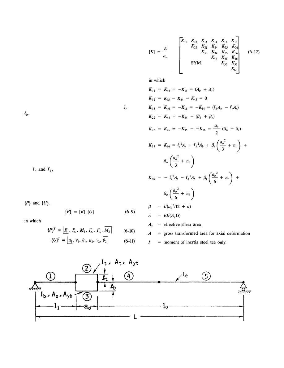
6.5 MATRIX
ANALYSIS
Donahey and Darwin (1987, 1986) developed a procedure to
obtain the total deflection of composite beams with web
openings that utilizes matrix analysis techniques. The pro-
cedure is applicable to noncomposite as well as composite
construction. The beam is represented as illustrated in Fig.
6.3. The nonperforated portions of a beam, sections 1, 4,
and 5 in Fig. 6.3, are represented in matrix analysis in the
normal manner. The sections above and below the opening
are represented using the properties of the individual tees,
including local eccentricities of the centroid of the tees with
respect to the centroid of the nonperforated section, and
The top and bottom tees are modeled by considering the
moments of inertia of the steel sections alone for local bend-
ing through the opening, the area of the steel webs for carry-
ing shear, and the gross transformed area of the cross sec-
tion for axial deformation.
Based on an analysis of test data, Donahey and Darwin
(1986) concluded that for the beams tested (lengths were 22
ft or less), the effect of shear deformation must be included
to obtain an accurate prediction of maximum deflection.
The model, as described above, including the eccentrici-
ties
can be easily included in most general-
purpose finite element programs. For less general programs
that do not have the capability to handle element eccentrici-
ties, the individual element stiffnesses, including eccentric-
ity, can be easily incorporated in a single element stiffness
matrix, [K], which relates global forces and displacements,
Fig. 6.3. Model of beam with web opening for use with matrix analysis (Donahey 1987, Donahey
& Darwin 1986).
53
© 2003 by American Institute of Steel Construction, Inc. All rights reserved.
This publication or any part thereof must not be reproduced in any form without permission of the publisher.
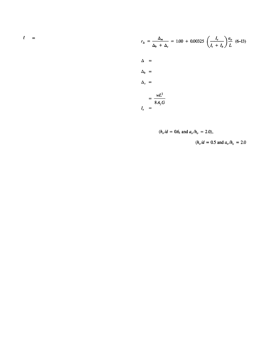
distance from center of gravity of unperforated beam
to center of gravity of a tee section.
Subscripts "t" and "b" indicate the top and bottom tees,
respectively.
This model gives generally accurate and conservative
results for maximum deflection in composite beams with
web openings and somewhat less accurate, but generally con-
servative, predictions for local deflections through web open-
ings (Donahey & Darwin 1986). The lack of composite
behavior for local bending through the web opening, as
represented by the use of the moment of inertia of the steel
tee section only for the top tee, takes into account the large
slip that occurs between the concrete and steel at web
openings.
Using this model, Donahey (1987) carried out a paramet-
ric study considering the effects of slab thickness relative
to beam size, opening depth-to-beam depth ratio, opening
length-to-depth ratio, and opening location. A total of 108
beam configurations were investigated. Based on this study,
Donahey concluded that the ratio of the midspan deflections
for beams with and without an opening, r, could be ade-
quately represented as
in which
maximum deflection of a beam with an opening due
to bending and shear
maximum deflection due to bending of a beam with-
out an opening
maximum deflection due to shear of a beam without
an opening
for a symmetrical, uniformly loaded beam
moment of inertia of unperforated steel beam or ef-
fective moment of inertia of unperforated compos-
ite beam
Donahey's analysis indicates that for the largest openings
evaluated the
deflection due
to the opening is approximately equal to the deflection due
to shear. For smaller openings
and smaller), openings increased deflection by less than 4
percent.
54
© 2003 by American Institute of Steel Construction, Inc. All rights reserved.
This publication or any part thereof must not be reproduced in any form without permission of the publisher.
REFERENCES
Aglan, Ahmed A., and Samih Qaquish, "Plastic Behavior
of Beams with Mid-Depth Web Openings," AISC Engi-
neering Journal 19:No.l (1982): 20-26.
____, and Richard G. Redwood, "Web Buckling in Castel-
lated Beams," Proceedings, Part 2, Institution of Civil En-
gineering (London), 57 (June 1974): 307-20.
American Institute of Steel Construction, Load and Resis-
tance Factor Design Manual of Steel Construction (Chi-
cago: AISC, 1986a).
____, Load and Resistance Factor Design Specification
for Structural Steel Buildings (Chicago: AISC, 1986b).
____, Specification for the Design, Fabrication and Erec-
tion of Structural Steel for Buildings (Chicago: AISC,
1978).
American Society of Civil Engineers, "Suggested Design
Guides for Beams with Web Holes," by the Subcommit-
tee on Beams with Web Openings of the Task Committee
on Flexure Members of the Structural Division, John E.
Bower, Chmn., ASCE Journal of the Structural Division
97:No.STll (November 1971: 2707-28; Closure to Discus-
sion, 99:No.St.6 (June 1973): 1312-15.
Bower, John E., "Ultimate Strength of Beams with Rectan-
gular Holes," ASCE Journal of the Structural Division
94:No.ST6 (June 1968): 1315-37.
Cato, S. L., Web Buckling Failure of Built-Up Girders with
Rectangular Holes, Master's Degree thesis, Oregon State
University, Corvallis, Oregon, 1964.
Cho Soon, "An Investigation on the Strength of Composite
Beams with Web Openings," M.S. Arch. Eng. Thesis,
Hanyong University, Seoul, Korea, December 1982.
____, and Richard G. Redwood, "The Design of Com-
posite Beams with Web Openings," Structural Engineering
Series No. 86-2 (Montreal: McGill University, June 1986).
Clawson, William C., and David Darwin, "The Design of
Composite Beams with Web Openings," Structural Engi-
neering and Engineering Materials SM Report No. 4,
Lawrence, Kas.: University of Kansas, October 1980.
Congdon, Judith, and Richard G. Redwood, "Plastic Be-
havior of Beams with Reinforced Holes," ASCE Journal
of the Structural Division 96:No.ST9 (September 1970):
1933-55.
Cooper, Peter B., and Robert R. Snell, "Tests on Beams with
Reinforced Web Openings," ASCE Journal of the Struc-
tural Division 98:No.ST3 (March 1972): 611-32.
____, Robert R. Snell, and Harry D. Knostman, "Failure
Tests on Beams with Eccentric Web Holes, ASCE Jour-
nal of the Structural Division 103:No.ST9 (September
1977): 1731-37.
Darwin, David, "Composite Beams with Web Openings,"
Proceedings, National Engineering Conference, American
Institute of Steel Construction, Chicago, March 1984; also
ASCE Journal of the Boston Society of Civil Engineers Sec-
tion 71:Nos.1&2 (1985): 67-83.
____, "Behavior and Design of Composite Beams with
Web Openings," chapt. 3 in Steel-Concrete Composite
Structures: Stability and Strength, R. Narayanan, ed. (Lon-
don and New York: Applied Science Publishers, 1988):
53-78.
____, and Rex C. Donahey, "LFRD for Composite Beams
with Unreinforced Web Openings," ASCE Journal of Struc-
tural Engineering 114:No.3 (March 1988): 535-52.
Donahey, Rex C., "Deflections of Composite Beams with
Web Openings," Building Structures, Proceedings, ASCE
Structures Congress, D. R. Sherman, ed., Orlando,
Flroida, August 1987: 404-17.
____, and David Darwin, "Performance and Design of
Composite Beams with Web Openings," Structural Engi-
neering and Engineering Materials SM Report No. 18, Uni-
versity of Kansas Center for Research, Lawrence, Kansas,
1986.
Donoghue, C. Michael, "Composite Beams with Web Open-
ings, Design," ASCE Journal of the Structural Division
108:No.ST12 (December 1982): 2652-67.
Dougherty, Brian K., "Elastic Deformation of Beams with
Web Openings," ASCE Journal of the Structural Division
106:No.STl (January 1980): 301-12.
____, "Buckling of Web Posts in Perforated Beams,"
ASCE Journal of the Structural Division 107:No.ST3
(March 1981): 507-19.
Ellingwood, Bruce, Theodore V. Galambos, James G. Mac-
Gregor, and C. Allin Cornell, Development of a
Probability-Based Load Criterion for American National
Standard A58-Building Code Requirements for Minimum
Design Loads in Buildings and Other Structures (Washing-
ton, D.C.: National Bureau of Standards, June 1980).
Frost, Ronald W, and Robert E. Leffler, "Fatigue Tests of
Beams with Rectangular Web Holes," ASCE Journal of
the Structural Division 97:No.ST2 (February 1971): 509-27.
Galambos, Theodore V., "Proposed Criteria for Load and
Resistance Factor Design of Steel Building Structures,"
Steel Research for Construction Bulletin No. 27 (Wa-
shington, D.C.: American Iron and Steel Institute, Janu-
ary 1978).
____, and Mayasandra K. Ravindra, "Tentative Load and
Resistance Factor Design Criteria for Steel Buildings,"
55
Clawson
, William C., and Darwin, David, "Tests of Composite
108:No.ST1 (January 1982a): 145-62.
Clawson, William C., and Darwin, David "Strength of Composite Beams
Beams with Web Openings", ASCE Journal of the Structural Division
with Web Openings", ASCE Journal of the Structural Division 108:
No.ST3 (March 1982b): 623-41.
Rev.
3/1/03
Donahey, Rex C., and Darwin, David, "Web Openings in Composite
Beams with Ribbed Slabs", ASCE Journal of Structural Engineering
114:No.3 (March 1988): 518-534.
Rev.
3/1/03
© 2003 by American Institute of Steel Construction, Inc. All rights reserved.
This publication or any part thereof must not be reproduced in any form without permission of the publisher.

56
Research Report No. 18 (St. Louis: Washington Univer-
sity, Civil Engineering Department, September 1973).
____, "Load and Resistance Factor Design Criteria for
Composite Beams," Research Report No. 44 (St. Louis:
Washington University, Civil Engineering Department,
April 1976).
Granade, Charles J., "An Investigation of Compostie Beams
Having Large Rectangular Openings in Their Webs," Mas-
ter's thesis, University of Alabama, at University, Ala-
bama, 1968.
Hansell, William C, Theodore V. Galambos, Mayasandra
K. Ravindra, and Ivan M. Viest, "Composite Beam
Criteria in LRFD," ASCE Journal of the Structural Divi-
sion 104: No.ST9 (September 1978): 1409-26.
Knostman, Harry D., Peter B. Cooper, and Robert R. Snell,
"Shear Force Distribution at Eccentric Web Openings,"
ASCE Journal of the Structural Division 103:
No. ST6,
(June 1977): 1216-21.
Kussman, Richard L., and Peter B. Cooper, "Design Ex-
ample for Beams with Web Openings," AISC Engineer-
ing Journal 13:No.2 (1976): 48-56.
Lucas, Warren K., and David Darwin, "Steel and Compos-
ite Beams with Web Openings," Report (Lawrence, Kas.:
University of Kansas Center for Research, 1990).
Lupien, Roger, and Richard G. Redwood, "Steel Beams with
Web Openings Reinforced on One Side " Canadian Jour-
nal of Civil Engineering 5 :No.4 (December 1978): 451-61.
McCormick, Michael M., "Open Web Beams—Behavior,
Analysis, and Design," BMP Report, MRL17/18 (Clayton,
Victoria, Australia: Melbourne Research Laboratories, The
Broken Hill Proprietary Company Limited, 1972a).
____, Discussion of "Suggested Design Guides for Beams
with Web Holes," ASCE Journal of the Structural Divi-
sion 98:No.ST12 (December 1972b): 2814-16.
Poumbouras, George, "Modification of a Theory Predict-
ing the Shear Strength of Composite Beams with Large
Web Openings," Project Report No. U83-20 (Montreal:
McGill University, Department of Civil Engineering and
Applied Mechanics, April 1983).
Redwood, Richard G., "Plastic Behavior and Design of
Beams with Web Openings," Proceedings, First Canadian
Structural Engineering Conference (Toronto: Canadian
Steel Industries Construction Council, February 1968a):
127-38.
_____, "Ultimate Strength of Beams with Multiple Open-
ings," Preprint No. 757, ASCE Structural Engineering Con-
ference, Pittsburgh, October 1968b.
____, "The Strength of Steel Beams with Unreinforced
Web Holes," Civil Engineering and Public Works Review
(London), 64:No.755 (June 1969): 559-62.
_____, "Simplified Plastic Analysis for Reinforced Web
Holes," AISC Engineering Journal 8:No.3 (1971): 128-31.
_____, "Design of I-Beams with Web Perforations," chapt.
4 in Beams and Beam Columns: Stability and Strength, R.
Narayanan, ed. (London and New York: Applied Science
Publishers, 1983): 95-133.
____, "The Design of Composite Beams with Web Open-
ings," Proceedings, First Pacific Structural Steel Confer-
ence, Aukland, New Zealand 1 (August 1986): 169-85.
____, Hernan Baranda, and Michael J. Daly, "Tests of
Thin-Webbed Beams with Unreinforced Holes," ASCE
Journal of the Structural Division 104:No.ST3 (March
1978): 577-95.
____, and John O. McCutcheon, "Beam Tests with Un-
reinforced Web Openings," ASCE Journal of the Struc-
tural Division 94:No.STl (January 1968): 1-17.
____, and George Poumbouras, "Tests of Composite
Beams with Web Holes," Canadian Journal of Civil Engi-
neering 10:No.4 (December 1983): 713-21.
____, and George Poumbouras, "Analysis of Composite
Beams with Web Openings," ASCE Journal of Structural
Engineering 110:No.ST9 (September 1984): 1949-58.
____, and Suresh C. Shrivastava, "Design Recommenda-
tions for Steel Beams with Web Holes," Canadian Jour-
nal of Civil Engineering 7:No.4 (December 1980): 642-50.
____, and Minoru Uenoya, "Critical Loads for Webs with
Holes," ASCE Journal of the Structural Division
105:No.ST10 (October 1979): 2053-76.
____, and Patrick K. Wong, "Web Holes in Composite
Beams with Steel Deck," Proceedings, Eighth Canadian
Structural Engineering Conference (Willowdale, Ontario:
Canadian Steel Construction Council, February 1982).
Todd, David M., and Peter B. Cooper, "Strength of Com-
posite Beams with Web Openings," ASCE Journal of the
Structural Division 106:No.ST2 (February 1980): 431-44.
Uenoya, Minoru, and Richard G. Redwood, "Buckling of
Webs with Openings," Computers and Structures 9:No.2
(1978): 191-99.
U.S. Steel Corp., Rectangular, Concentric and Eccentric
Reinforced Web Penetrations in Steel Beams—A Design Aid,
rev. ed., ADUSS 27-8482-02 (Pittsburgh, Penn.: U.S.
Steel Corp., April 1986).
____, Rectangular, Concentric and Eccentric Unreinforced
Web Penetrations in Composite Steel Beam—A Design Aid,
ADUSS 27-8482-01 (Pittsburgh, Penn.: U.S. Steel Corp.,
October 1984).
____, Rectangular, Concentric and Eccentric Unreinforced
Web Penetrations in Steel Beams—A Design Aid, ADUSS
27-7108-01 (Pittsburgh, Penn.: U.S. Steel Corp., June
1981).
Wang, Tsong-Miin, Robert R. Snell, and Peter B. Cooper,
"Strength of Beams with Eccentric Reinforced Holes,"
ASCE Journal of the Structural Division 101:No.ST9 (Sep-
tember 1975): 1783-99.
Wiss, Janney, Elstner Associates, Structural Investigation of
a Typical Floor Beam at the 200 West Adams Building, Chi-
cago, WJE No. 840795 (Northbrook, 111.: W.J.E. Assoc.,
Inc., August 1984).
© 2003 by American Institute of Steel Construction, Inc. All rights reserved.
This publication or any part thereof must not be reproduced in any form without permission of the publisher.

ADDITIONAL BIBLIOGRAPHY
57
Aglan, Ahmed A., and Richard G. Redwood, "Elastic and
Inelastic Instability of Webs Between Holes," Structural
Mechanics Series, No. 73-5 (Quebec, Canada: McGill Uni-
versity, 1973).
Bower, John E., "Elastic Stresses Around Holes in Wide-
Flange Beams," ASCE Journal of the Structural Division
92:No.ST2 (April 1966): 85-101.
____, "Experimental Stresses in Wide-Flange Beams with
Holes," ASCE Journal of the Structural Division
92:No.ST5 (October 1966): 167-86.
____, "Design of Beams with Web Openings," ASCE
Journal of the Structural Division, 94:No.ST3 (March
1968): 783-807.
Brock, J. S., "The Stresses Around Square Holes with
Rounded Corners," Journal of Ship Research 2:No.2
(1958):37-41.
Brockenbrough, Roger L., "Design Aids for Beams with
Eccentric-Unreinforced-Rectangular Web Holes," Research
Bulletin (Pittsburgh, Penn.: U.S. Steel Corp., 22 October,
1980).
____, "Ultimate-Strength Tables for Beams with
Eccentric-Unreinforced-Rectangular Web Holes," Research
Bulletin (Pittsburgh, Penn.: U.S. Steel Corp., 10 Novem-
ber 1976).
____, "Design Aids for Beams with Composite Beams
with Unreinforced-Rectangular Web Holes," Research
Bulletin (Pittsburgh, Penn., U.S. Steel Corp., 7 July 1983).
Chan, Peter W., "Approximate Methods to Calculate Stresses
Around Circular Holes," Fourth Progress Report to Cana-
dian Steel Industries Construction Council, Project 695,
November 1971.
____, and Richard G. Redwood, "Stresses in Beams with
Circular Eccentric Web Holes," ASCE Journal of the Struc-
tural Division 100:No.ST.l (January 1974): 231-48.
Darwin, David, "Web Openings in Composite Bams," Com-
posite Construction in Steel and Concrete, C. D. Buckner
and I. M. Viest, eds. (New York: American Society of Civil
Engineers, 1988): 270-85.
Deresiewicz, Herbert, "Stresses in Beams Having Holes of
Arbitrary Shape," ASCE Journal of the Engineering
Mechanics Division 94:No.EM5 (October 1968): 1183-1214.
Douglas, Terry R., and Samuel C. Gambrell, "Design of
Beams with Off-Center Web Openings," ASCE Journal
of the Structural Division 100:No.ST6 (June 1974):
1189-1203.
Frost, Ronald W., "Behavior of Steel Beams with Eccentric
Web Holes, Technical Report 46.019-400 (Monroeville,
Penn.: U.S. Steel Corp., Applied Research Laboratory,
February 1973).
Gibson, J. E., and W. M. Jenkins, "The Stress Distribution
in a Simply Supported Beam with Circular Holes," Struc-
tural Engineer (London) 34:No.l2 (December 1956):
443-49.
Gotoh, K., "The Stresses in Wide-Flange Beams with Web
Holes," Theoretical and Applied Mechanics (University of
Tokyo Press) 23 (1975): 223-42.
Halleux, Pierre, "Limit Analysis of Castellated Steel Beams,"
Acier Stahl Steel No. 3 (March 1967): 133-44.
Heller, S. R., "The Stresses Around a Small Opening in a
Beam Subjected to Bending with Shear," Proceedings, 1st
U.S. National Congress of Applied Mechanics (Chicago:
ASME, 1951): 239-45.
____, "Reinforced Circular Holes in Bending with Shear,"
Journal of Applied Mechanics 20 (June 1953): 279-85.
_____, J. S. Brock, and R. Bart, "The Stresses Around a
Rectangular Opening with Rounded Corners in a Uni-
formly Loaded Plate," Proceedings, 3rd U.S. National
Congress of Applied Mechanics (ASME, 1958): 357-68.
____, J. S. Brock, and R. Bart, "The Stresses Around a
Rectangular Opening with Rounded Corners in a Beam
Subjected to Bending with Shear," Proceedings, 4th U.S.
National Congress of Applied Mechanics (ASME, Vol. 1,
1962): 489-96.
Hoglund, T., "Strength of Thin Plate Girders with Circular
or Rectangular Web Holes Without Web Stiffeners," Re-
ports of the Working Commissions (IABSE Colloquium,
London, Vol. 11, 1971): 353-65.
Kussman, Richard L., "Ultimate Load Tests on Steel Beams
with Reinforced Eccentric Web Openings," M.S. Thesis,
Kansas State University, Manhattan, Kansas, 1975.
____, and Peter B. Cooper, "Design Example for Beams
with Web Openings," AISC Engineering Journal 13:No.2
(1976): 48-56.
Larsen, Marvin A., and Kirit N. Shah, "Plastic Design of
Web Openings in Steel Beams," ASCE Journal of the
Structural Division 102:No.ST5 (May 1976): 1031-41.
Lupien, Roger, "Web Openings in Steel Beams Reinforced
on One Side," M. Eng. Thesis, McGill University, Mon-
treal Quebec, Canada, 1977.
McLellan, T. J., "Effects of Openings in Webs of Steel
Girders," paper presented at the Convention of the Struc-
tural Engineers Association of California, State Line,
Nevada, October 1964.
McCutcheon, J. O., J. F. Dickie, and S. Y. Cheng,
"Experimental Investigation of Large Extended Open-
ings in the Webs of Wide-Flange Beams," Applied
Mechanics Series No. 6 (Montreal: McGill University,
April 1965).
© 2003 by American Institute of Steel Construction, Inc. All rights reserved.
This publication or any part thereof must not be reproduced in any form without permission of the publisher.

Shrivastava, Suresh C, and Richard G. Redwood, "Web In-
stability Near Reinforced Rectangular Holes," IABSE
Proceedings No. P-6 (August 1977).
____, and Richard G. Redwood, "Shear Carried by
Flanges at Unreinforced Web Holes," Technical Note,
ASCE Journal of the Structural Division 105:No.ST8
(August 1979): 1706-11.
Swartz, Stuart E., and Krigo S. Eliufoo, "Composite Beams
with Web Openings," ASCE Journal of the Structural Di-
vision, Technical Note, 106:No.ST5 (May 1980):
1203-1208.
Uenoya, M., and H. Ohmura, "Finite Element Method for
Elastic Plastic Analysis of Beams with Holes," paper
presented at Japan Society of Civil Engineers, National
Meeting, Fukuoka, Japan, October 1972.
U.S. Steel Corp., Design of Beams with Web Openings,
ADUSS 27-3500-01 (Pittsburgh, Penn.: U.S. Steel Corp.,
1968).
____, USS Building Design Data—Design of Beams with
Web Openings, ADUSS 27-3500-01 (Pittsburgh, Penn.:
U.S. Steel Corp. (April 1968).
Van Oostrom, J., and A. N. Sherbourne, "Plastic Analysis
of Castellated Beams. II. Analysis and Tests," Computers
and Structures 2:No.1/2 (February 1972): 11-40.
Wang, Chi-Kia, "Theoretical Analysis of Perforated Shear
Webs," ASME Transactions 13 (December 1946):
A77-A84.
____, W. H. Thoman, and C. A. Hutchinson, "Stresses
in Shear Webs Contiguous to Large Holes," Internal Re-
port (Boulder, Colo.: University of Colorado, 1955).
Worley, W. J., "Inelastic Behavior of Aluminum Alloy
I-Beams with Web Cutouts," Bulletin No. 44 (Urbana, Ill.:
University of Illinois, Engineering Experiment Station,
April 1958).
58
____, W. C. So, and B. Gersovitz, "A Study of the Ef-
fects of Large Circular Openings in the Webs of Wide-
Flange Beams, Applied Mechanics Series No. 2 (Montreal:
McGill University, November 1963).
Narayanan, R., and K. C. Rockey, "Ultimate Load Capacity
of Plate Girders with Webs Containing Circular Cut-Outs,"
Proceedings, Part 2 (London: Institution of Civil Engi-
neers, Vol. 71, 1981): 845-62.
Porbandarwalla, A. G., "Ultimate Load Capacity of Steel
Beams with Web Openings by the Finite Element Method,"
M.S. Thesis, Kansas State University, Manhattan, Kansas,
1975.
Redwood, Richard G., "Stresses in Webs with Circular
Openings," Final Report to the Canadian Steel Industries
Construction Council, Research Project No. 695 (Decem-
ber 1971).
____, "Tables for Plastic Design of Beams with Rectan-
gular Holes," AISC Engineering Journal 9:No.l (1972):
2-19.
____, Design of Beams with Web Holes (Canadian Steel
Industries Construction Council, 1973).
____, and Peter W. Chan, "Design Aids for Beams with
Circular Eccentric Web Holes," ASCE Journal of the Struc-
tural Division 100:No.ST2 (February 1974): 297-303.
Rockey, K. S., R. G. Anderson, and Y. K. Cheung, "The
Behaviour of Square Shear Webs Having a Circular Hole,"
Thin Walled Steel Structure, edited by K. C. Rockey and
H. V. Hill (London: Crosby Lockwood, 1969): 148-72.
Segner, Edmund P., "Reinforcement Requirements for Girder
Web Openings," ASCE Journal of the Structural Division
90:No.ST3 (June 1964): 147-64.
Sherbourne, A. N., and J. Van Oostrom, "Plastic Analysis
of Castellated Beams. I. Interaction of Moment, Shear,
and Axial Force," Computers and Structures 2: No. 1/2
(February 1972): 79-109.
© 2003 by American Institute of Steel Construction, Inc. All rights reserved.
This publication or any part thereof must not be reproduced in any form without permission of the publisher.
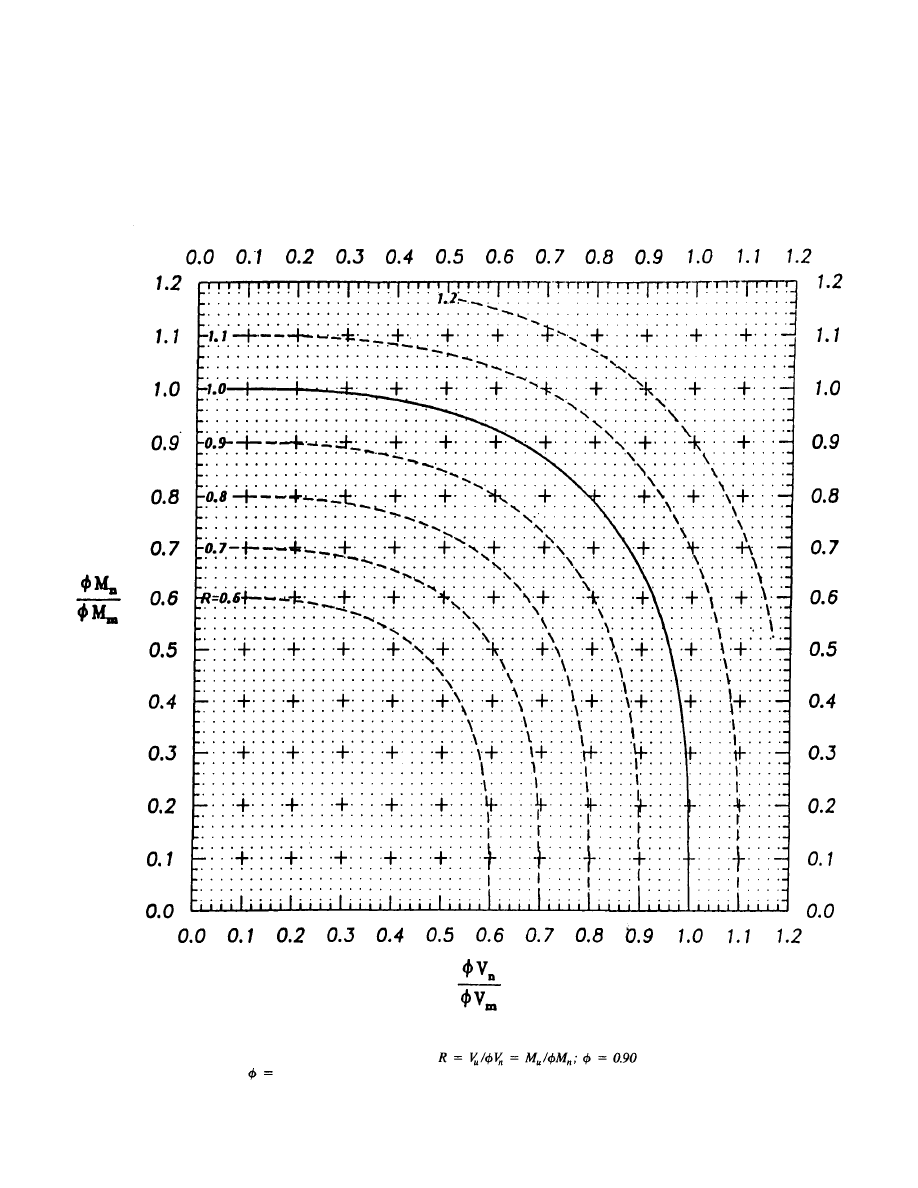
APPENDIX A
59
Fig. A.I. Moment-shear interaction curves.
for steel beams;
0.85 for composite beams.
© 2003 by American Institute of Steel Construction, Inc. All rights reserved.
This publication or any part thereof must not be reproduced in any form without permission of the publisher.
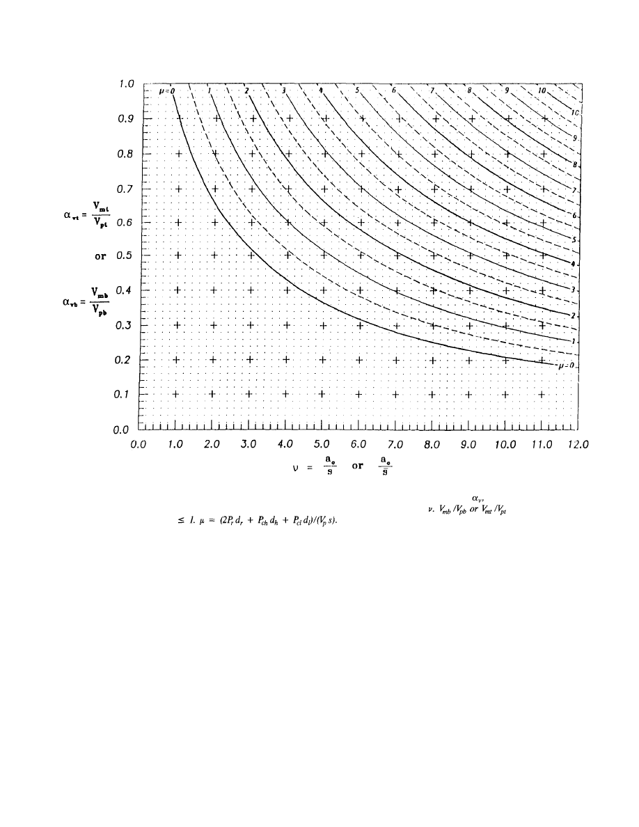
60
Fig. A. 2. Ratio of maximum nominal shear strength to plastic shear strength of a tee,
versus
length-to-depth ratio or effective length-to-depth ratio of the tee,
© 2003 by American Institute of Steel Construction, Inc. All rights reserved.
This publication or any part thereof must not be reproduced in any form without permission of the publisher.
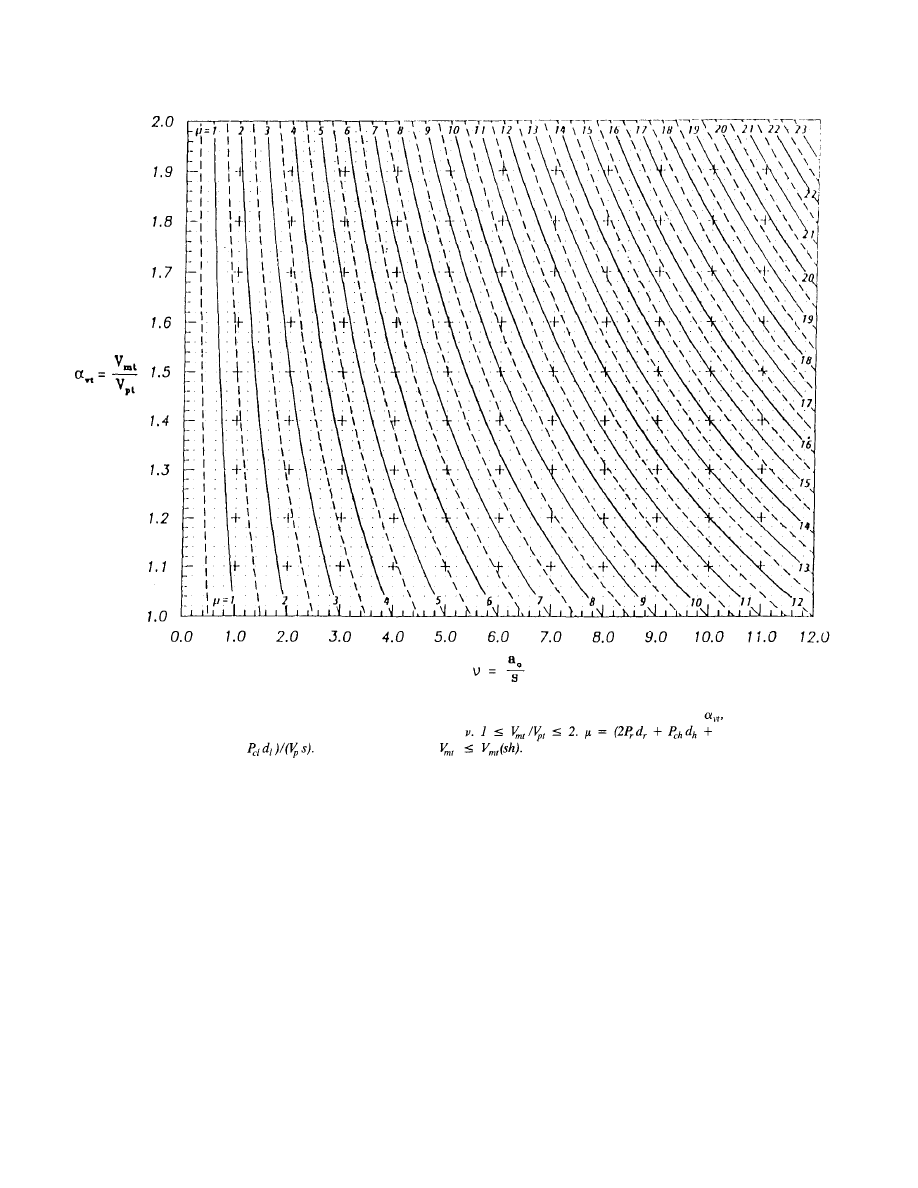
Fig. A3. Ratio of maximum nominal shear strength to plastic shear strength of the top tee,
versus length-to-depth ratio of the tee,
Check to ensure that
61
© 2003 by American Institute of Steel Construction, Inc. All rights reserved.
This publication or any part thereof must not be reproduced in any form without permission of the publisher.
INDEX
bearing stiffeners, 15
behavior, 37
bottom tee, 3
bridging, 3, 39
bridging in, 50
circular openings, 15, 16, 21, 49, 51
compact section, 38
compact sections, 42
composite beam, 11, 43, 47
deflections, 51
deformation, 37
design interaction curves, 8
detailing, 21
detailing beams, 12, 48
dimensions, 49
failure, 38
failure modes, 37
general yielding, 38
high moment end, 3
interaction curves, 8, 42, 59
lateral bracing, 49
lateral buckling, 14, 49
local buckling, 13, 38, 48
low moment end, 3
matrix analysis, 53
moment-shear interaction, 8
multiple openings, 39, 51
opening, 49
opening configurations, 9
opening dimensions, 15, 21, 25, 32
opening parameter, 3, 13, 48
opening shape, 39
plastic hinges, 38
plastic neutral axis, 3
post-crack strength, 50
primary bending moment, 3
proportioning, 12, 21, 48
rectangular openings, 16
reinforced opening, 24
reinforced openings, 9, 30, 42
reinforced web openings, 15, 18, 20
reinforcement, 3, 15, 21, 27, 33, 35, 39, 50
reinforcement, slab, 3
resistance factors, 7
secondary bending, 38
secondary bending moments, 3, 44
shear capacity, 10
shear connectors, 16, 21, 39, 50
slab reinforcement, 16, 21, 35, 50
spacing of openings, 16, 21
stability, 21, 35, 48
stability considerations, 12
tee, 3
top tee, 3
unperforated member, 3
unreinforced, 30
unreinforced opening, 22, 27
unreinforced openings, 9, 42
unreinforced web openings, 15, 17, 19
Vierendeel, 38, 51, 52
von Mises, 45
web buckling, 13, 48
63
Rev.
Rev.
3/1/03
3/1/03
Rev.
3/1/03
© 2003 by American Institute of Steel Construction, Inc. All rights reserved.
This publication or any part thereof must not be reproduced in any form without permission of the publisher.

DESIGN GUIDE SERIES
American Institute of Steel Construction, Inc.
One East Wacker Drive, Suite 3100
Chicago, Illinois 60601-2001
Pub. No. D 8 0 2 (3M1093)
© 2003 by American Institute of Steel Construction, Inc. All rights reserved.
This publication or any part thereof must not be reproduced in any form without permission of the publisher.
Wyszukiwarka
Podobne podstrony:
Design Guide 05 Design of Low and Medium Rise Steel Buildings
Eurocode 3 Part 3 2 2006 Design of Steel Structures Towers, Masts and Chimneys Chimneys
Eurocode 3 Part 1 3 2006 UK NA Design of steel structures General rules Supplementary rules for
Eurocode 3 Part 1 7 2009 Design of Steel Structures Plated Structures Subject to Out of Plane Loa
Eurocode 3 Part 2 2006 UK NA Design of steel structures Steel bridges
Eurocode 3 Part 1 9 2005 UK NA Design of Steel Structures Fatigue
Eurocode 3 Part 1 4 2006 Design of Steel Structures General rules Supplementary Rules for Stainl
Eurocode 3 Part 1 9 2005 Design of Steel Structures Fatigue
Eurocode 3 Part 1 5 2009 Design of Steel Structures Plated Structural Elements
Eurocode 3 Part 1 12 2007 UK NA Design of Steel Structures Additional Rules for the Extension of
Eurocode 3 Part 1 11 2006 Design of Steel Structures Design of Structures With Tension Components
Eurocode 3 Part 1 11 2005 UK NA Design of Steel Structures Design of Structures with Tension Com
Eurocode 3 Part 1 2 2005 UK NA Design of steel structures General rules Structural fire design
Eurocode 3 Part 1 12 2007 Design of Steel Structures Additional Rules for the Extension of EN 199
DESIGN OF HYBRID PHOTOVOLTAIC POWER GENERATOR, WITH OPTIMIZATION OF ENERGY MANAGEMENT
DESIGN OF A SWITCHING MODE POWER SUPPLY WITH UPS FEATURES
Green, Simon R Nightside 02 Angels of Light and Darkness
Effects of topography and composition of titanium surface ox
więcej podobnych podstron