GEK-?????
5000 Series Programmer’s Manual
1
CHAPTER 2. ANSI EMULATION
CONTROL CODE AND ESCAPE SEQUENCE ACTIVITY LEVELS
ANSI control codes and escape sequences are assigned activity levels
depending on which print mode is currently active. The following
charts provide Information on what to expect from the control codes
and escape sequences in each printing mode.
I-IGNORED
No noticeable effect on printing will occur.
V-VALID
These sequences will not affect the printing mode in
progress, but
will
take effect when normal printing
resumes.
A–ACTIVE
This sequence will take effect immediately.
D–DATA
These control codes are used as data.
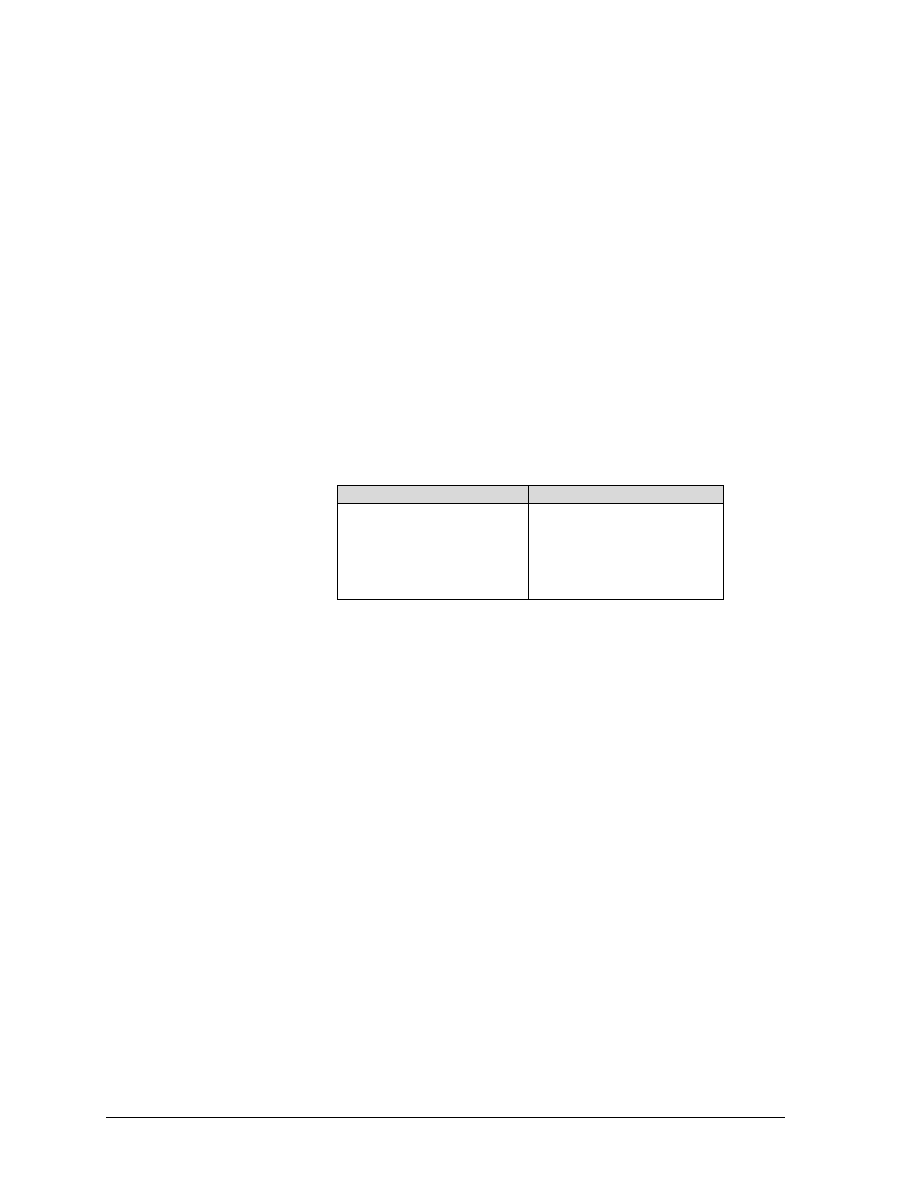
Notes
Note 1
If printer option 1 is active, either in ANSI (4800) or
ANSI (4410) emulation, SO and SI will activate or
deactivate this printing mode. SO and ST are VALID in
bar codes and oversize-ACTIVE in expanded. Please
see Appendix G, Description of Strapping options,
tables 5 and 6 on page Error! Bookmark not defined.
for details on options which affect printer operation in
ANSI emulation.
Note 2
VALID during enhanced oversize-ACTIVE during
normal oversize.
Note 3
Discarded while in the native mode.
Note 4
Will cause an error symbol to print (XOX).
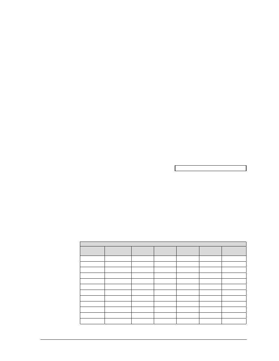
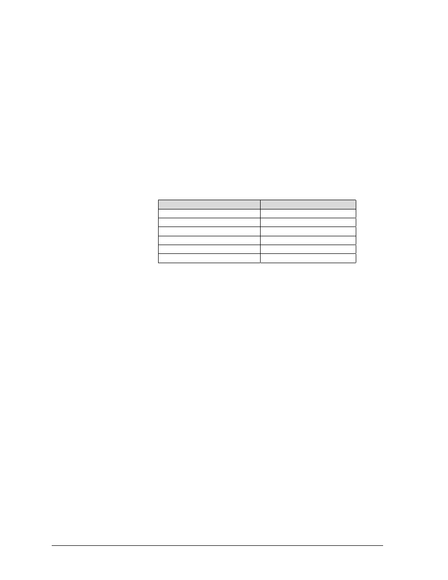
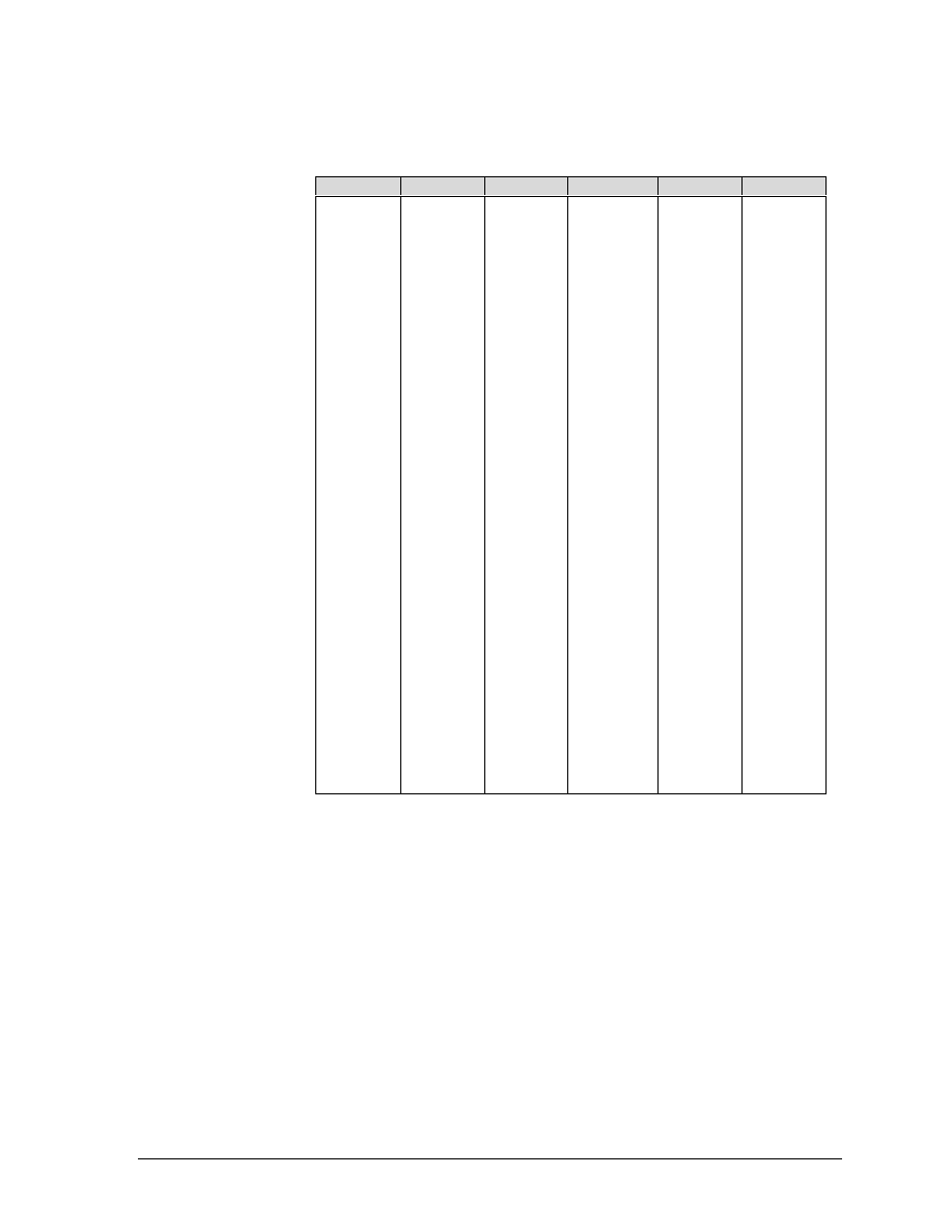
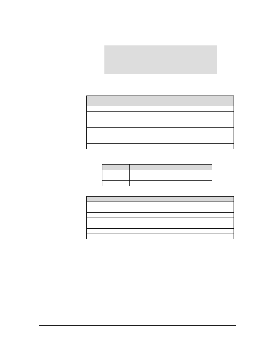
Control Code Activity Levels
Control Code Activity Levels
Control
Code
Line
Terminator
Normal
Dot
Graphics
Bar Codes
Oversize
POSTNET
BEL
No
A
A
D
A
Note 4
BS
Yes
A
I
I
I
Note 4
CR
Yes
A
A
I
A
Note 4
DC1
No
A
A
D
A
Note 4
DC3
No
A
A
D
A
Note 4
DEL
No
Note 3
Note 3
D
Note 3
Note 4
FF
Yes
A
A
I
A
Note 4
HT
No
A
A
A
A
A
LF
Yes
A
A
I
A
Note 4
SI
No
A
I
Note 1
Note 1
Note 4
SO
No
A
I
Note 1
Note 1
Note 4
VT
Yes
A
A
I
A
Note 4
ANSI Emulation
GEK-99???
2
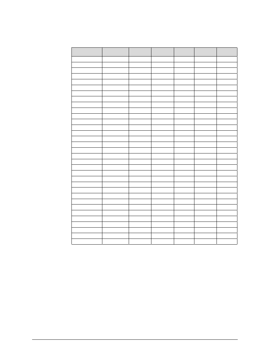
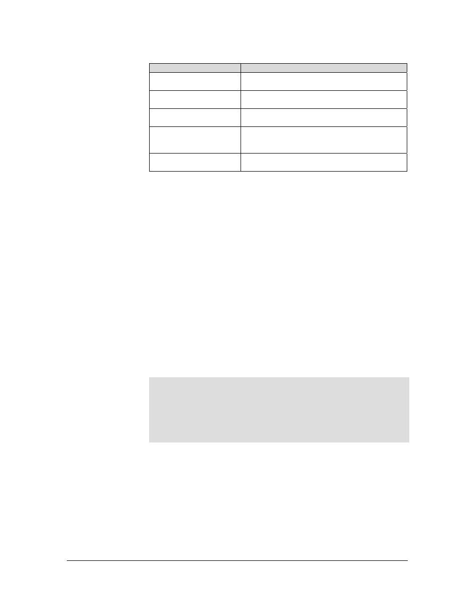
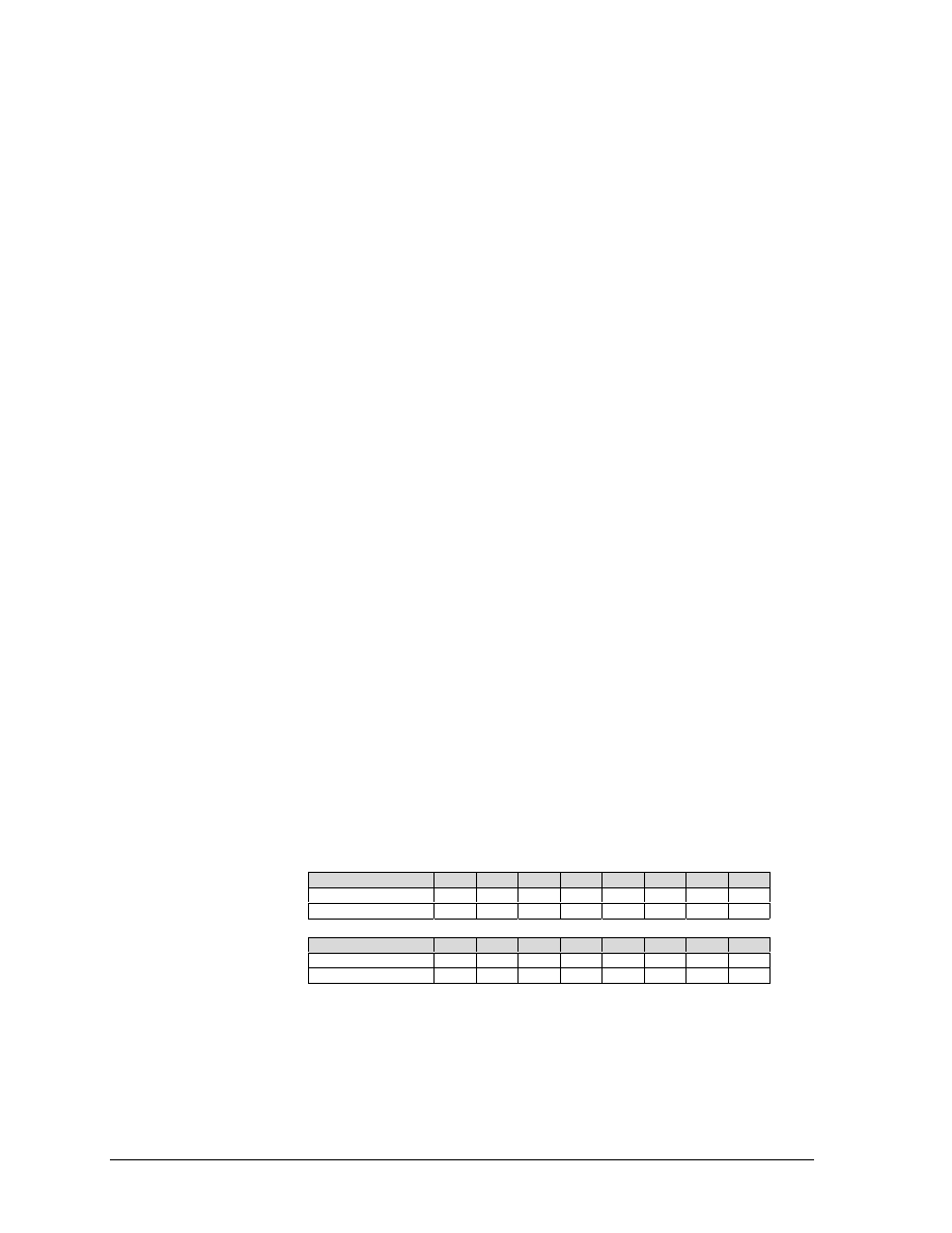
Escape Sequence Activity Levels
Escape
Sequence
Line
Terminator
Normal
Dot
Graphics
Bar
Codes
Oversize POSTNET
DCS (Graphics)
No
A
I
I
A
I
Font Load
No
A
I
I
A
I
GENBCS
No
A
A
A
A
I
GENFD
No
A
A
A
A
I
GENGRM
No
A
V
A
A
I
GENHTS
No
A
A
A
A
I
GENOSM
No
A
V
V
A
I
GENSLR
No
A
A
A
A
I
GENSNC
No
A
V
V
Note 2
I
GENSPM
No
A
V
A
A
A
GENTST
Yes
A
A
I
A
I
GENVFU
Yes
A
A
A
A
I
DENVTS
No
A
A
A
A
I
GSM
No
A
V
V
A
I
HPA
Yes
A
A
A
A
I
HPB
Yes
A
A
A
A
I
HPR
No
A
A
A
A
I
HTS
No
A
A
A
A
I
HVP
Yes
A
A
A
A
I
PLD
Yes
A
I
I
A
I
PLU
Yes
A
I
I
A
I
REP
No
A
A
I
A
I
RIS
No
A
A
A
A
I
RM
No
A
A
A
A
I
SGR
No
A
V
V
Note 2
I
SM
No
A
A
A
A
I
SPI
No
A
V
V
Note 2
I
ST
No
I
A
I
I
I
TBC
No
A
A
A
A
I
VFU Load
No
A
I
I
A
I
VPA
Yes
A
A
A
A
I
VPB
Yes
A
A
A
A
I
VPR
Yes
A
A
A
A
I

GEK-?????
5000 Series Programmer’s Manual
3
CONTROL CODE DEFINITIONS
BEL
Bell (07H): Receipt of a BEL code causes the beeper to sound for
approximately 1/2 second after any preceding printable data has been
processed.
BS
Back Space (08H): Line terminator. The paper position remains
unchanged and the print position is moved left one character space
at the current CPI. If the print position is at the left margin no action
is taken.
CR
Carriage Return (0DH): Line terminator. The print position is reset to the
left margin and the paper position is left unchanged.
CSI
Control Sequence Introducer (9BH): Signals the beginning of an ANSI
control sequence. When 8-bit data is used. CSI (9BH) can be substituted for
ESC [ (1BH 5BH). Also see ESC.
DC1
Device Control 1 (11H): Parallel and Serial Interface: Receipt of a
DC1 code with the printer in local mode puts the printer online
(SELECTS printer) and enables receipt of data.
Through CCU menu options, a serial interface protocol may be
selected that transmits a DC1 code to the host to signal that the printer is
ready to receive data.
DC3(Device Control 3 – 13H): Parallel and Serial Interface: Receipt of a DC3 code w
Through menu options, a serial interface protocol may be
selected that
transmits a DC3 code to the host to signal that the printer Is not ready to
receive data.
ESC
Escape (1BH): Signals the beginning of an escape sequence. See also
CSI, above.
NOTE
The print position can also be set to the left margin via the
CCU control panel menu using the SETUP/FORMAT/MODIFY
FORMAT/PRINT CONTROL menu selection.
NOTE
The print position can also be set to the left margin via the
CCU control panel menu using the SETUP/FORMAT/MODIFY
FORMAT/PRINT CONTROL menu selection.

ANSI Emulation
GEK-99???
4
FF
Form Feed (0CH): Line terminator. The paper is advanced to the
next
top of form position. If the EVFU is enabled and programmed, paper will
advance to the next stop in channel 1.
HT
Horizontal Tab (09H): Advances the print position to the next
horizontal tab location. If no tabs are set, an HT code is either converted to a
space or ignored, depending on menu option settings.
LF
Line Feed (0AH): Line terminator. The paper is advanced to the
next
line. When printing horizontal dot graphics, the paper is advanced to the next
dot row.
NOTE: an option strap from the CCU control panel menu using the
SETUP/FORMAT/MODIFY FORMAT/GENPRTOPTS selection can
disable This feature.
SI
Shift In (0FH): Used to exit a Special Print Mode (GENSPM) when
printer control strap A9 (Appendix G) is set.
SO
Shift Out (0EH): Used to enable a special, print mode (GENSPM)
when ANSI emulation strap 1 is reset.
VT
Vertical Tab (0BH): Line terminator. The paper is advanced to
the
next vertical tab stop. If no tabs are set, a VT code causes a line feed. When
using the EVFU, paper advances to the next stop in channel 12.
NOTE: an option strap from the CCU control panel menu using the
SETUP/FORMAT/MODIFY FORMAT/GENPRTOPTS selection can
disable This feature.
NOTE
An option strap from the CCU control panel menu using the
SETUP/FORMAT/MODIFY FORMAT/GENPRTOPTS selection
can disable This feature.
GEK-?????
5000 Series Programmer’s Manual
5
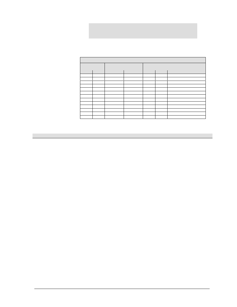
ESCAPE SEQUENCE DIRECTORY
Sequence
Meaning
Page
CSI or ESC [
Control Sequence Introducer
CSI p1 p2 SP ~
GENEMU: Select emulation
ESC [p1 ; p2 SP B
GSM: Modifies vertical (p1) and horizontal (p2)
character size
ESC [p1 ; p2 SP G
SPI: Sets LPI (p1) and/or CPI (p2) in decipoints
ESC H
HTS: Set a tab at current print position
ESC J
VTS: Set a tab at current paper position
ESC K
PLD: Moves print line down 3/72 inch (subscript)
ESC L
PLU: Moves print line up 3/72 inch (superscript)
ESC P
DCS: Introduces dot graphics
ESC Q
Self-Test: Inactive. Sequence ignored.
ESC [ p1 a
HPR: Moves print position right p1 distance (relative)
ESC [p1 b
REP: Dot graphics: repeat preceding character p1
times
ESC c
RIS: Resets printer to a known initial state
ESC [ p1 d
VPA: Sets vertical position to p1 decipoints or lines
ESC [ pl e
VPR: Moves paper forward p1 decipoints
ESC [ p1; p2 f
HVP: Moves paper and print position (absolute)
ESC [ p1 g
TBC: Clears tabs: p1=3 for horizontal
ESC [ p1 ; p... h
SM: Set mode (PUM, LNM, proportional. character
mapping)
ESC [ p1 j
HPB: Moves print position left by decipoints or
columns
ESC [ p1 k
VPB: Moves paper backward by decipoints or lines
ESC [ p1 ;p ... l
RM: Reset mode (PUM, LNM, proportional, character
mapping)
ESC [ p1;p ... m
SGR: Selects font styles and enhancements
ESC [ p1 p2 ! p
GENVF2: EVFU vertical paper movement command
ESC [ p1 ; p2 SP n
ESC [ p1 ; p2 ; p3 SP q
GENGRM: Selects graphics horizontal and vertical dot
densities
ESC [ p1; p2 ; p3 r
GENFD: Sets form length (pl), margins - top (p2),
bottom (p3)
ESC [ p1; p2 s
GENSLR: Sets margins. Left (p1), right (p2) in
decipoints
ANSI Emulation
GEK-99???
6
Sequence
Meaning
Page
ESC [ p1 t
Selects bar codes p1=3, quit bar code p1=0
ESC [ p1;pn u
GENHTS: Sets horizontal tabs (p1, etc.) in decipoints
or columns
ESC [ p1 ; p12 v
GENVTS: Sets vertical tabs (p1, etc.) in decipoints or
lines
ESC [ p1 x
GENSNC: Selects international character sets
ESC [ p1; ...;p10 }
Selects barcode parameters
ESC [ p1 SP }
GENDFC: Download Font Control: checks printer for
downloaded font
OSC or ESC ]
Operating System Command: introduces sequence
ESC ] 5
Not implemented. Sequence ignored.
ESC ] 9
Not implemented. Sequence ignored.
ESC ] !
Begins 12-channel EVFU table loading
ESC \
ST: String Terminator. Exits special modes
ESC [ p1 `
HPA: Horizontal Position Absolute
ESC [ p1 |
OSC 9 ; p1 ; ... ; p8-pn
ST
Character Map Load

GEK-?????
5000 Series Programmer’s Manual
7
ANSI ESCAPE SEQUENCE CATEGORIES
The ANSI escape sequences have been separated according to
functionality. Special areas of interest, such as graphics and the
electronic vertical format unit (EVFU), have been described in
separate sections. The functional groups are:
Housekeeping
Paper and Print Positioning
Margins and Tabs
Font Handling and Enhancements
Graphics
EVFU
ANSI Emulation
GEK-99???
8
Housekeeping Sequences
ESC [
CSI (Control Sequence Introducer): This sequence is used to begin
sequences, which generally have multiple parameters.
ESC ]
OSC (Operating System Command): This is another special
sequence introducer. Sequences which begin with OSC require the
ST string terminator sequence (ESC \) to end them.
ESC \
ST (String Terminator): Used to terminate the loading of EVFU
tables. download fonts, and dot graphics strings.
ESC c
RIS (Reset to Initial State): Resets the printer to either the standard
state shown below or to the state stored in the customer save area of
memory. The RIS sequence can be disabled by ANSI option strap 3
(see Appendix G, tables 5 and 6, option 3).
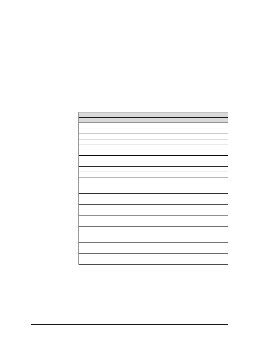
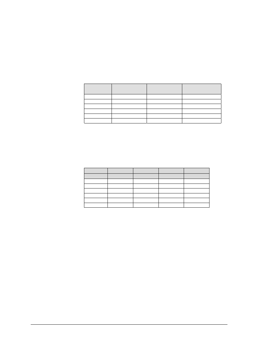
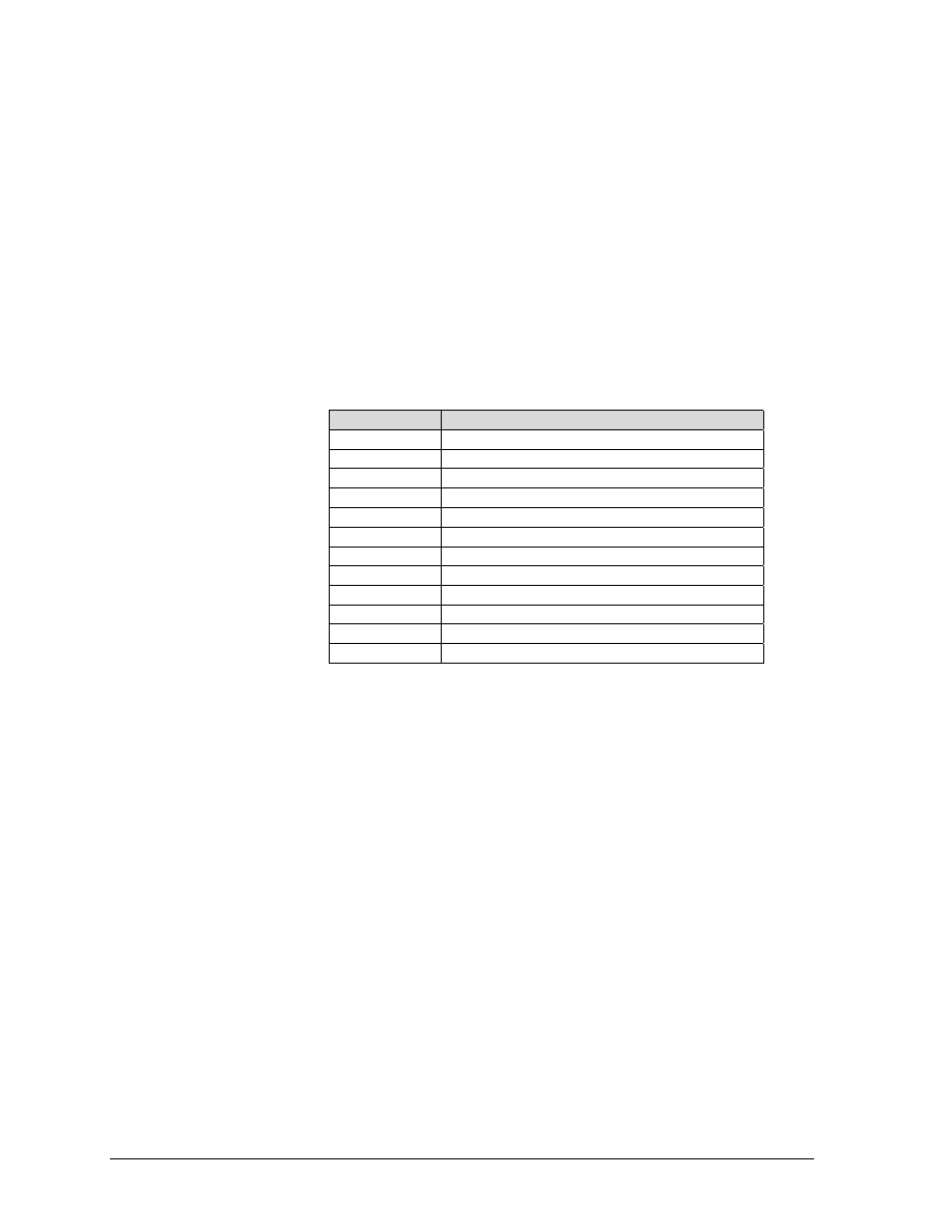
RIS – Reset to Initial State
Parameter
State
Font Style
Gothic Draft
Character Size
1X Vertical. 1X Horizontal
Character Pitch
10 CPI
Country Selection
USA
Code Page
457
Line Spacing
6 LPI
Partial Line Up
Reset
Partial Line Down
Reset
Bold Print
Inactive
Underline Mode
Inactive
Expanded Mode
Inactive
Proportional Mode
Reset
Horizontal Tab Table
Empty
Left Margin
None - Column 0
Right Margin
None - Maximum
Form Number
7
Page Size
7920 decipoints/ 66 lines/11 inches
Top Margin
None
Bottom Margin
None
Forms Position
Top of form - current position
Vertical Tab Table
Empty
Vertical Format Unit
Default
Graphics Density
60 H DPI, 72 V DPI, horizontal format
VFU Load In Progress
Exit (nothing saved)
Bar Code Mode
Inactive
Dot Graphics
Inactive
Decimal
27 99:
Hex:
1B 63
BASIC:
CHR$(27);"c";

GEK-?????
5000 Series Programmer’s Manual
9
ESC Q
GENTST (Self-Test): This sequence is ignored.
Decimal:
27 102 or 120
Hex:
1B 5C or 9C
BASIC:
CHR$(27);"\";
ANSI Emulation
GEK-99???
10
CSI p1 p2 SP ~
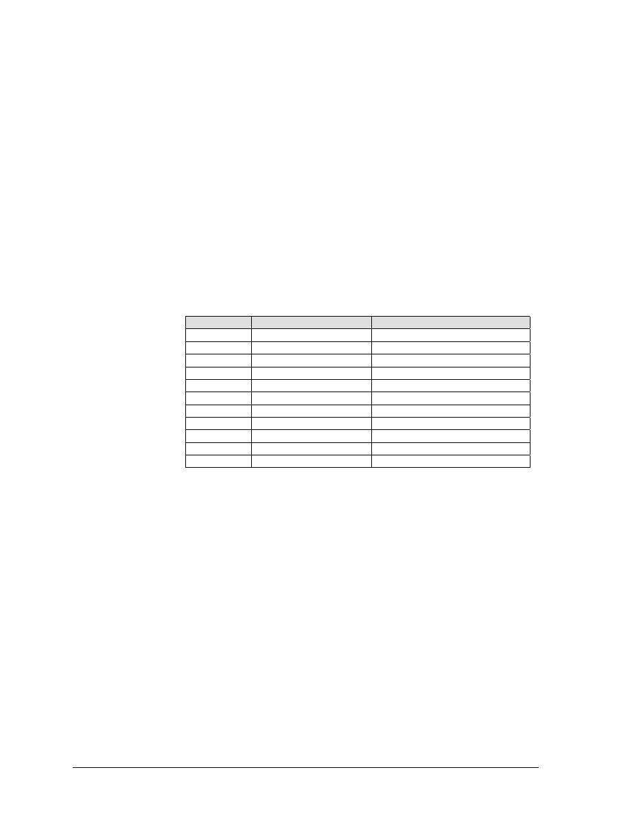
GENEMU (Emulation Control): This sequence will switch the control
for the printer to another emulation. The parameters in the sequence
are defined as follows:
p1
Emulation identifier. This parameter will select the particular
emulation by a reference number as supplied by GENICOM
engineering. The assigned numbers may be found in the table
below.
p2
Reset control. The parameters of the printer to be reset or
defaulted are controlled by this parameter. It will not always
be possible to meet the strict definition of this parameter, so
each printer will have a definition of how the reset control is
implemented. The values as currently defined are:
0
Hold values (default). All possible values for printer
control (tabs, margins, page length, etc.) are to be
retained.
1
Full reset. Reset parameters to initial state.
p1
Manufacturer
Emulation
0
GENICOM
ANSI
10
GENICOM
4410 ANSI
1-19
GENICOM
Reserved
20
IBM
Graphics Printer
21
IBM
Proprinter XL 9-wire
22
Epson
FX286-e
23
IBM
Proprinter XL 24-wire
24
Epson
LQ2500
30
Data Products
ANSI
40
Printronix
P300
41
Printronix
P5008
Indeterminate Conditions
If no emulation parameter is supplied, the emulation will remain in
the current state and the rest of the sequence is ignored. Other
parameter values and other parameters are reserved.
Mnemonic:
CSI p1 p2 SP ~
Decimal:
27 101 p1 p2 32 126
Hex:
1B 5B p1H p2H 20 7E
BASIC:
CHR$(27);"p1p2 ~";
GEK-?????
5000 Series Programmer’s Manual
11
Character Set Selection
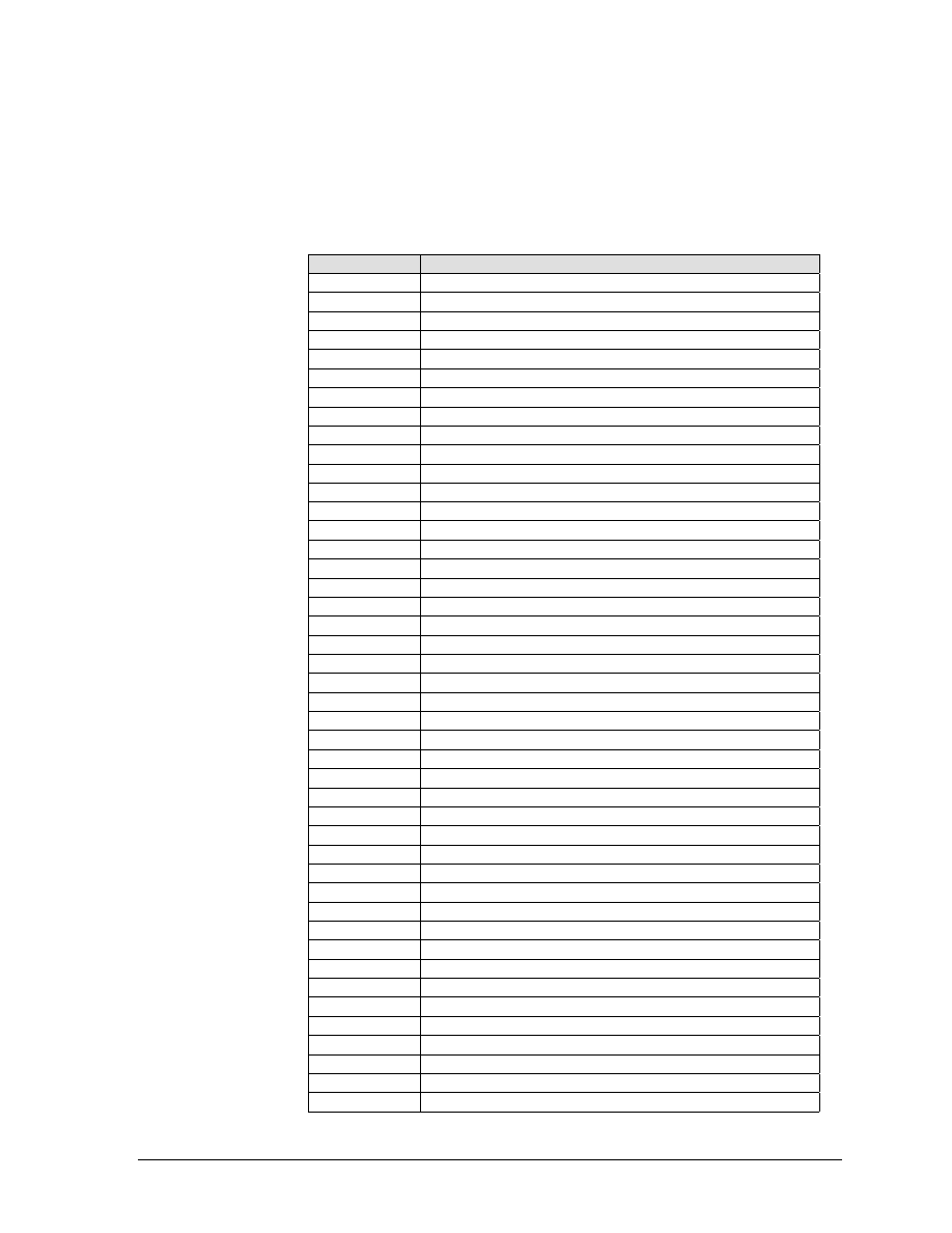
ESC [ p1 x
GENSNC (Select National Characters): This sequence selects the
national character substitution if the currently selected character
style supports it. The following values may be used for p1.
p1
Country Map or Character Set
0
USA (ISO)
1
German (ISO)
2
French A (ISO)
3
French B
4
French Canadian
5
Dutch (Netherlands)
6
Italian
7
United Kingdom (ISO)
8
Spanish
9
Danish/Norwegian A
10
Danish/Norwegian B
11
Danish/Norwegian C
12
Danish/Norwegian D
13
Swedish/Finnish A
14
Swedish/Finnish B
15
Swedish/Finnish C
16
Swedish/Finnish D
17
Swiss
18
(Ignored)
19
Yugoslavian
20
United Kingdom A
21
Turkish
22
Greek
23
Italian (ISO)
24
Spanish (ISO)
437
IBM PC USA (MS Code Page 437)
850
IBM PC Multilingual (MS Code Page 850)
852
Microsoft Code Page 852 (East Europe)
853
Microsoft Code Page 853 (Turkey)
855
Microsoft Code Page 855 (Cyrillic)
860
Microsoft Code Page 860
863
Microsoft Code Page 863 (French Canadian)
864
Microsoft Code Page 864
865
Microsoft Code Page 865
866
Microsoft Code Page 866 (Russian)
867
Microsoft Code Page 867
8572
USSR GOST (Russian)
8573
Greek Code Page 437
8574
DEC Multinational (LA-210)
8575
Roman 8
8576
Polish Mazowia
8577
Turkish 8-bit Code Page
8578
Greek Code Page 851
8591
ISO 8859-1 Latin Alphabet #1
ANSI Emulation
GEK-99???
12
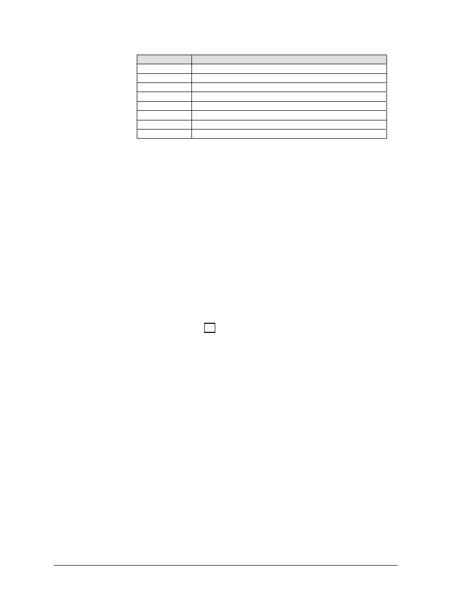
p1
Country Map or Character Set
8592
ISO 8859-2 Latin Alphabet #2
8593
ISO 8859-3 Latin Alphabet #3
8594
ISO 8859-4 Latin Alphabet #4
8595
ISO 8859-5 Latin/Cyrillic
8596
ISO 8859-6 Latin/Arabic
8597
ISO 8859-7 Latin/Greek
8598
ISO 8859-8 Latin/Hebrew
8599
ISO 8859-9 Latin Alphabet #5
Character Map Load
OSC 9 ; p1 ; ... ;
Character Map Load: This sequence signals the beginning of a
p8-pn ST
Character Map Load data transfer. Character map definitions, which
follow this sequence, are stored in non-volatile memory. The
character map is selected with the GENICOM Select National
Characters (GENSNC) command using the p2 parameter that is
specified in the load sequence for this command. The load is
terminated by a String Terminator (ST) sequence. The downloaded
character map replaces the USA ISO character set in character map
memory.
A single character map containing 128 substitutions may be
specified. A character map may be designated for either the GL table
(codes 20H-7EH) or the GR table (codes 80H-FFH). Any substitutions
not specified within a character map load will be mapped one-to-one.
For example, code 41H will print the character normally found at
location 41H (upper case A). When a character map designated as a
GR map is selected by the GENSNC command (see Character Set
Selection on page 11), the GL map will automatically be mapped
one-to-one. A standard GL (7-bit) character map, such as French A,
may be specified as the base for a downloaded GR (8-bit) character
map, but an 8-bit GR map, code page 866, for example, may NOT be
used as the base for a GL character map.
The complete syntax for the Character Set Load is shown below:
OSC 9 ; p1 ; p2 ... ; p8–pn ST
p1
Control Command
0
Store new character map
1
Erase existing character. In this case, parameters p2-
pn are ignored and need not be supplied. An existing
downloaded character map need not be erased before a
new character map is loaded.
All other values of p1 are reserved.
p2
GENSNC (CSI p1 x) select parameter. Values must be between
90 and 99 in order not to interfere with GENICOM standard
character maps. If a downloaded character map select
parameter is a value other than 90 through 99, the download
character map command will be ignored.
p3
Reserved. This parameter is marked by inserting a semi-colon
(;) in the command sequence.

GEK-?????
5000 Series Programmer’s Manual
13
p4
Reserved. This parameter is marked by inserting a semi-colon
(;) in the command sequence.
p5
Reserved. This parameter is marked by inserting a semi-colon
(;) in the command sequence.
p6
A literal string indicating the GENSNC select parameter of an
existing character map (such as 437, 850, etc.) to be used as
a base in which substitutions from this command sequence
may be made. This string may be up to 10 characters in
length and must be specified only if the downloaded character
map is to use an existing map as a base. The string is
terminated by a semi-colon (;). The base character map will
always default to Code Page 437 if an ACT character map is
specified and the downloaded character map is a GR table. If
the downloaded map is a GL table, p6 must specify an
existing GL table as the base or a one-to-one default base will
be used.
p7
A literal string which will be used to identify the character
map in the Progam Mode Font – Country menu. This string
may be up to 20 characters in length and is terminated by a
semi-colon (;). Note that only the first 11 characters of this
string will be used for display purposes.
p8-pn A trio of parameters used to specify the actual character map
substitution. A semi-colon must separate each parameter
within the trio, and a semi-colon must terminate each trio.
The semi-colon is not required for the last trio that
immediately precedes the String Terminator (ESC \).
The elements of each trio are defined as follows:
1 A decimal number that identifies the destination
character. This is the character value received from the
host. For example, an upper case "A" has a decimal value
of 65. Values of 32 through 126 and 128 through 255 are
valid for this element.
The first element processed in the first substitution trio
will define whether the map will be for GL (7-bit) or GR
(8-bit) substitution. If the first element is between 32 and
126 (inclusive), the map will be GL, and the first element
of each trio must also be between 32 and 126. Likewise, if
the first element of the first trio is between 128 and 255,
the map is a GR map and all first elements must fall
between 128 and 255. The character substitution map will
be discarded if this rule is violated.
2 A decimal number that identifies the source character.
This is the location value of the desired character pattern
in the printer font set. For example, an upper case "A" has
a decimal value of 65. Values of 0 through the last

ANSI Emulation
GEK-99???
14
available character for the currently selected font are valid
for this element.
3 Reserved. A semi-colon (;) is required to mark this element
position. A zero is permitted.

GEK-?????
5000 Series Programmer’s Manual
15
Paper and Print Position Moves
ESC K
PLD (Partial Line Down): Line terminator. The print line is moved
down 3/72 inch for subscript printing. Also used to return to the
original line following a partial line up (ESC L - superscript)
sequence. See note below.
Decimal:
27 75
Hex:
1B 4B
BASIC:
CHR(27)$;"K";
ESC L
PLU (Partial Line Up): Line terminator. The print line is moved up
3/72 inch for superscript printing. Also used to return to the original
line following a partial line down (ESC K - subscript) sequence. See
note.
Decimal:
27 76
Hex:
1B 4C
BASIC:
CHR$(27);"L";
ESC [ p1 a
HPR (Horizontal Position Relative): Line terminator. Moves the
print position to the right of the current position. The distance
specified by the p1 parameter is in decipoints. An HPR move
exceeding the right margin sets the print position at the margin. If
the p1 parameter is zero or missing, the command is ignored.
Decimal:
27 91 p1 97
Hex:
1B 5B p1 61
BASIC:
CHR$(27);"[p1a";
NOTE
In the native mode, these sequences can be used in succession
to advance or reverse the paper to another line. In the 4000
compatibility mode, they can be used in pairs to change from
superscript directly to subscript or subscript directly to
superscript, but can not be used to position the paper.
Also see the SScript: ON/OFF menu selection in the User's
Manual.
ANSI Emulation
GEK-99???
16
ESC [ p1 d
VPA (Vertical Position Absolute): Line terminator. Sets the vertical
position to the value specified by p1, moving paper forward or
backward to the new position. The distance specified by the p1
parameter is in decipoints. This command can be used to print inside
top and bottom margins. If the specified position is not within the
current page, the command is ignored. If the parameter value is
omitted or less than 5 decipoints, it will result in the vertical position
being set to the top of form position.
Decimal:
27 91 p1 100
Hex:
1B 5B p1H 64
BASIC:
CHR$(27);"[“;CHR$(p1);”d";
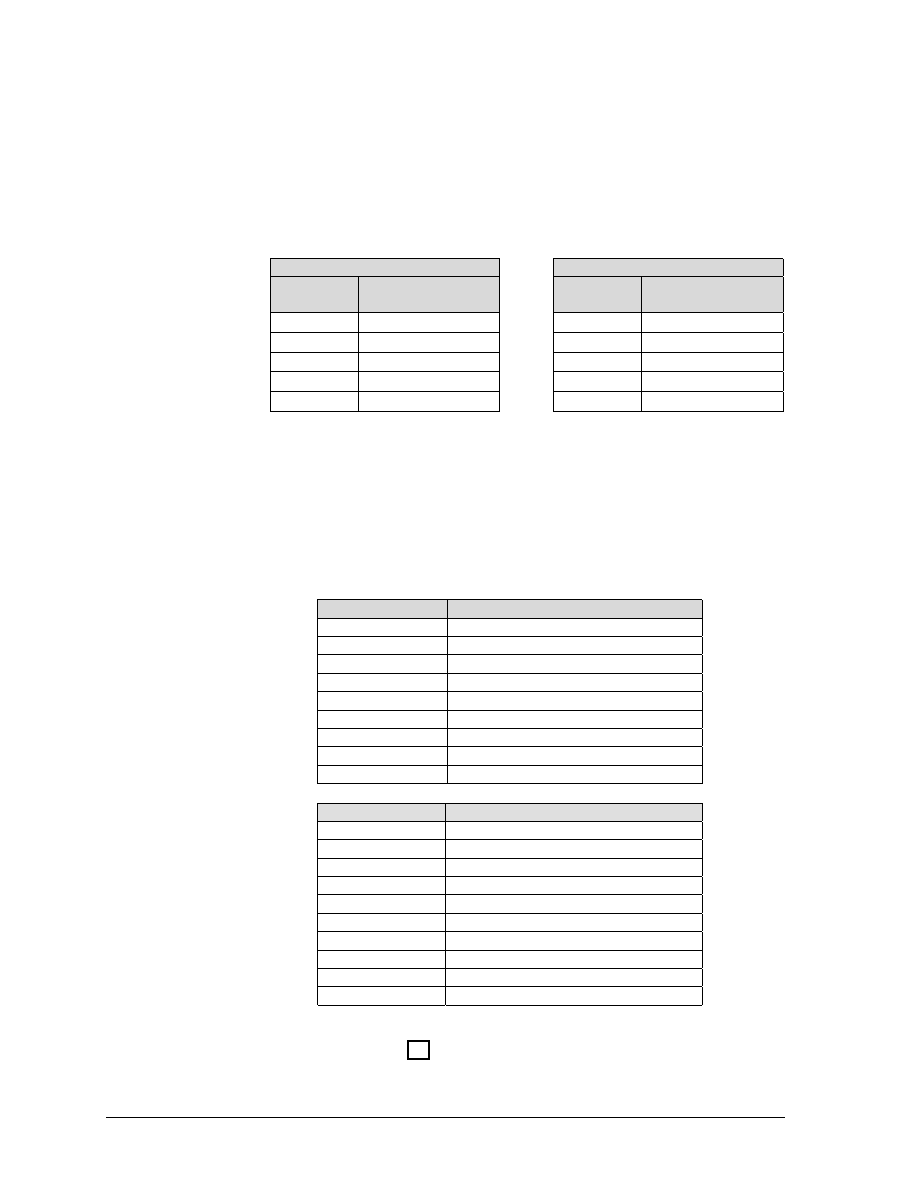
ESC [ p1 e
VPR (Vertical Position Relative): Line terminator. Increases the
current vertical position by the value specified by p1. Decipoints are
converted to provide the 1/144-inch moves shown in the table.
Decipoint Value
Movement In Inches
Missing or 0 - 4
No Movement
5-9
1/144 inch
10-14
2/144 inch
15-19
3/144 inch
17,280 or greater
24 inches
Decimal:
27 91 p1 95
Hex:
1B 5B plH 65
BASIC:
CHR$(27);"[“;CHR$(p1);”e";
ESC [ p1 ; p2 f
HVP (Horizontal and Vertical Position): Line terminator. Sets the
vertical paper position to the value of p1 and the print position to the
p2 value. Values are sent as decipoints. HVP can position printing
inside margins. The vertical position can not exceed the form length
and the horizontal position cannot exceed the maximum width for the
printer.
Decimal:
27 91 p1 52 96
Hex:
1B 5B p1H 3B p2 66
BASIC:
CHR$(27);”[“;CHR$(p1);”;”;CHR$(p2);”f";
ESC [ p1 j
HPB (Horizontal Position Backward): Line terminator. Moves the
print position left of the current position by the distance specified in
p1. Values are sent as decipoints. The print position is set to the left
margin if the p1 value would exceed the margin. An HPB with a p1
value of zero is ignored.
Decimal:
27 91 p1 106
Hex:
1B 5B p1H 6A
BASIC:
CHR$(27);"[“;CHR$(p1);”j";

GEK-?????
5000 Series Programmer’s Manual
17
ESC [ p1 k
VPB (Vertical Position Backwards): Line terminator. Moves the
paper in reverse by the distance specified by p1. Values can be sent
as decipoints. The paper position is set to the top margin if the p1
value would exceed the margin. A VPB with a p1 value of 5 decipoints
or less is ignored.
Decimal:
27 91 p1 107
Hex:
1B 5B p1H 6B
BASIC:
CHR$(27);"[p1k";
ESC [ p1 ’
HPA (Horizontal Position Absolute): Line terminator. Moves the
print position to the value specified in p1. Values are sent as
decipoints. Position zero is column one. The print position is set to
the right margin if the p1 value would exceed the margin. An HPB
with a p1 value greater than 9,504 is ignored.
Decimal:
27 91 p1 96
Hex:
1B 5B p1 60
BASIC:
CHR$(27);"[p1'";

ANSI Emulation
GEK-99???
18
Margins and Tabs
ESC H
HTS (Horizontal Tab Set): Sets a tab at the current print position
and updates any existing horizontal tab table. A total of 22 tabs can
be set if this number is exceeded, the leftmost 22 tabs will be
retained.
Decimal:
27 72
Hex:
1B 48
BASIC:
CHR$(27);"H";
ESC J
VTS (Vertical Tab Set): Sets a tab at the current paper position and
updates any existing vertical tab table. A total of 12 tabs can be set.
If this number is exceeded, the 12 tabs closest to the top of the page
will be retained.
Decimal:
27 74
Hex:
1B 4A
BASIC:
CHR$(27);"J";
ESC [ p1 g
TBC (Tab Clear): Clears horizontal or vertical tab stops based on the
p1 value as follows:
p1 = 0
Clear horizontal tab at current print position.
p1 = 1
Clear vertical tab at current paper position.
p1 = 3
Clear all horizontal tabs.
p1 = 4
Clear all vertical tabs.
More than one parameter can be used.
Example: To clear all horizontal and vertical tabs, send:
ESC [ 3 ; 4 g
Decimal:
27 101 p1 103
Hex:
1B 5B p1 67
BASIC:
CHR$(27);"[p1;"g";
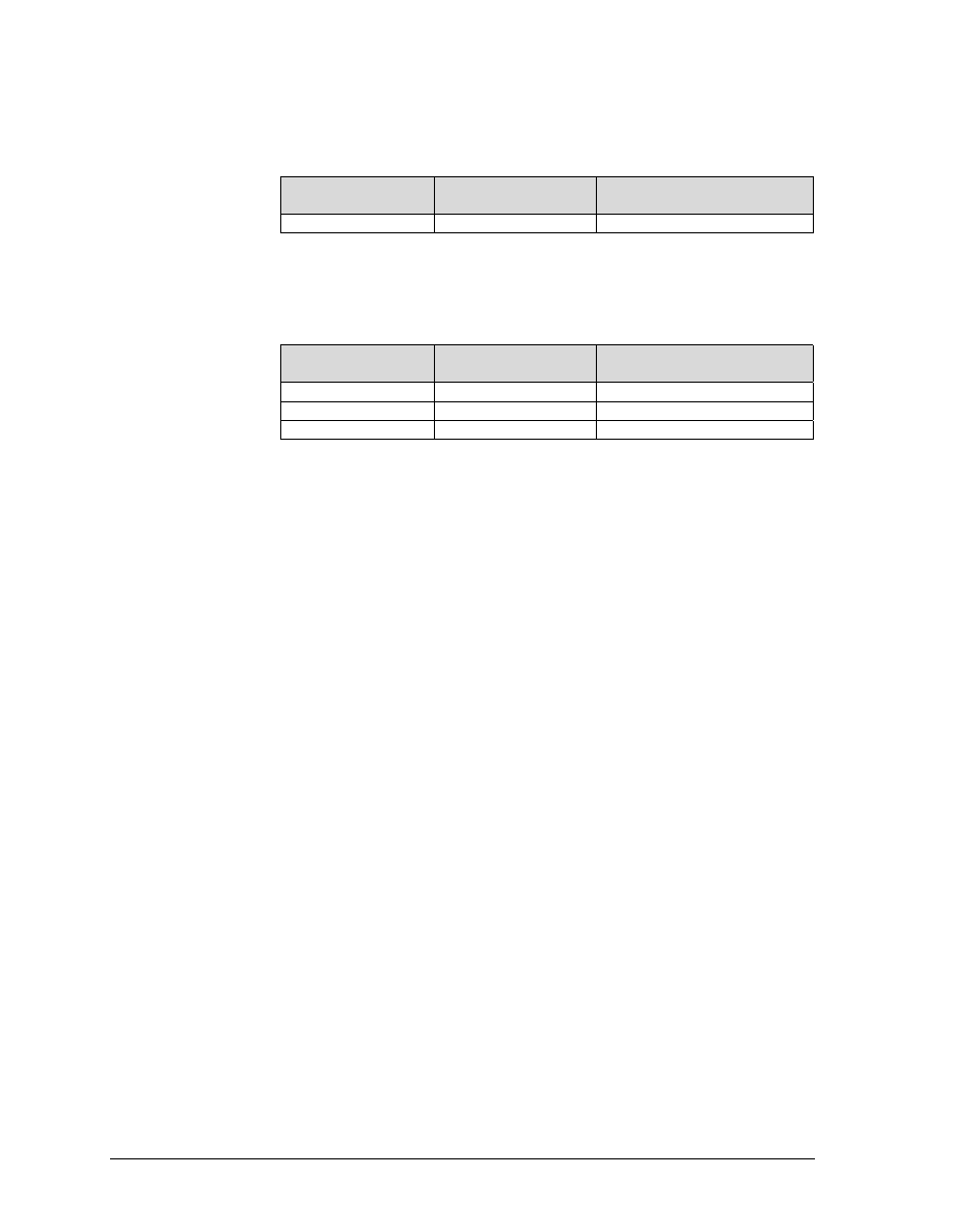
ESC [ p1; p2 ; p3 r
GENFD (Forms Definition): Establishes the form length (p1), the top
margin (p2), and the bottom margin (p3) in decipoints. Default
parameters are for an 11-inch (7,920 decipoints) long form with a top
and bottom margin of zero.
p1 - maximum allowable length is 24 inches (17,280 decipoints).
p2 - top of page to first print line
p3 - top of page to last printable line.
Decimal:
27 91 p1 p2 p3 r
Hex:
1B
BASIC:
GEK-?????
5000 Series Programmer’s Manual
19
Sequence
Explanation
ESC [r
Default values of 11-inch form length, zero
top and bottom margins.
ESC [8280r
11.5-inch form length, default top and
bottom margins of zero
ESC [;720r
Default length of 11 inches, top margin of
I inch.
Default bottom margin of zero.
ESC [;;7200r
Default length of 11 inches, default top
margin of zero, and a 1-inch bottom
margin.
ESC [7920:360:7560r
11-inch form length, ½-inch top and
bottom margins
Decimal:
27 91 p1 p2 p3 114
Hex:
1B 5B p1H p2H p3H 72
BASIC:
CHR$(27);"[";CHR$(p1);CHR$(p2);CHR$(p3);"r";
ESC [ p1; p2 s
GENSLR (Set Left/Right Margins): The p parameters are distances
from the left edge of the printable area of the paper. Parameter p1
sets the left margin and p2 sets the right margin. An omitted
parameter clears that margin. Invalid parameters will set the left
margin to zero (column 1) and the right margin to 9,504 decipoints
(column 132 at 10 cpi for the 13.2-inch machines).
A new left margin takes effect following any line terminator that
normally calls for a print position set to the left. A new right margin
takes effect when the print position reaches the new margin.
Margin settings stored as decipoint values are enforced to the nearest
1/120 of an inch. Character printing operates at 1/120 of an inch.
Decimal:
27 91 p1 p2 115
Hex:
1B 5B p1H p2H 73
BASIC:
CHR$(27);"[";CHR$(p1);CHR$(p2);"s";
NOTE
There is a physical left margin of .6 to 1.6 inches from the edge of the
paper to the first printable column. This distance is adjustable by
sliding all four tractors sideways. The margins set with this sequence
begin at the first physical print position, not at the edge of the paper.

ANSI Emulation
GEK-99???
20
ESC [ p1 ; p ...; u
GENHTS (Multiple Horizontal Tab Set): Sets up to 22 horizontal
tabs. The p parameters are set in decipoints.
If more than 22 tabs are set, the highest numbered tabs (farthest
right) will be pushed out of the tab table. Tabs set in front of the left
margin, or beyond the right margin. are not usable. Moving the
margins will make them active.
Example: To place tabs at columns 10, 20, and 40 at 10 cpi, send
ESC [10;40;20u (tabs can be specified in any order).
Decimal:
27 101 p1 59 p2 59 … p22 59 117
Hex:
1B 5B p1 3B p2 3B ... 3B p22 3B 75
BASIC:
CHR$(27);"[p1;p2;p . . . ;u"
ESC [ p1 ; …; p12 ; v GENVTS (Multiple Vertical Tab Set): Sets up to 12 vertical tabs.
The p parameters are set in decipoints. If more than 12 tabs are set,
the 12 tabs nearest the top of form will be retained. If a tab is set in
the top margin area, it will be stored but will not be active until the
margin is moved. If a tab is set beyond the bottom margin,
attempting to move to that tab will advance the paper to the next top
of form.
Decimal:
27 101 p1 59 p2 59 … p12 59 118
Hex:
1B 5B p1 3B p2 3B … p12 3B 76
BASIC:
CHR$(27);”[p1;p2;...p12;v";

GEK-?????
5000 Series Programmer’s Manual
21
Font Handling and Enhancements
ESC [ p1; p2 SP B
GSM (Graphic Size Modification): This sequence modifies the
vertical (p1) and horizontal (p2) size of expanded and oversized
characters. When using expanded characters, the currently selected
font style is used. Oversize uses its own distinct font style.
Parameter values are percentages of the normal sized character, so
values over 100 are needed for expansion. Expansion factors are
obtained by dividing values by 100.
Example: A parameter value of 526 would be divided by 100 to
produce an expansion factor of 5 (5X expansion). Values less than
100 are treated as 1X expansion.
X1: 0-199 (Default)
X4: 400-499 X7: 700-799
X2: 200-299
X5: 500-599 X8: 800-UP
X3: 300-399
X6: 600-699
Mixed sizes within a line can be top or bottom justified depending on
the Program Mode menu option (see VExOpt:Default and
VExOpt: Baseline).
The top of an expanded character is used as the starting point for
vertical paper moves (line feed). The top or bottom of oversize
characters can be used depending on the state of menu option
GENPRTOPTS/Group 2, Strap 13.
When this sequence is received with a value of 200 or more,
expanded printing will start, providing the printer is in the text mode
(not bar codes. oversize, etc.
Examples:
ESC [;200 B
X1 Vertical
X2 Horizontal
ESC [200;200 B
X2 Vertical
X2 Horizontal
ESC [800;400 B
X8 Vertical
X4 Horizontal
During vertically expanded printing, blank lines (lines with no printed
characters) are not expanded from the current lpi setting.
Decimal:
27 101 p1 59 p2 32 66
Hex:
1B 5B p1 3B p2 20 42
BASIC:
CHR$(27);"[p1;p2 B";
ANSI Emulation
GEK-99???
22
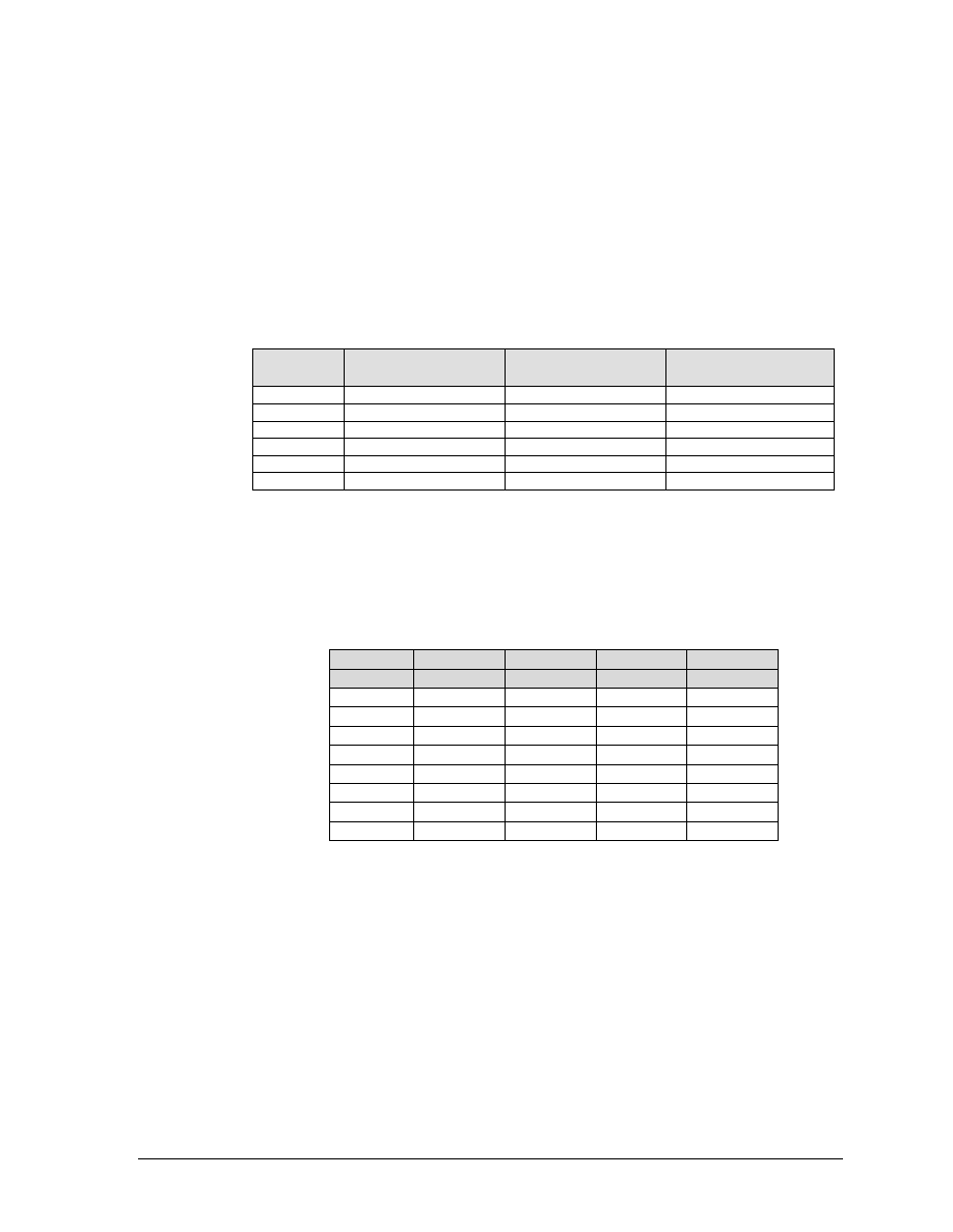
ESC [ p1 ; p2 SP G
SPI (Spacing Increment): This sequence is used to set line spacing
(p1) and character spacing or pitch (p2). If the parameter is missing
or zero, the spacing will remain unchanged. In the native mode, p1
can range from 1 to 17,820 decipoints (24 inches). The printable area
(between the, top and bottom margin) can not be exceeded. The range
of p2 is dependent on the font and will be ignored if exceeded.
Examples of Spacing Values
LPI Spacing
CPI Spacing
LPI
p1
(decipoints)
CPI
p2
(decipoints)
3
240
10
72
4
180
12
60
6
120
13.3
54
8
90
15
42
16.7
36
Decimal:
27 91 p1 59 p2 32 71
Hex:
1B 5B p1 3B p2 20 47
BASIC:
CHR$(27);"[p1;p2 G";
ESC [ p1 ; pn... m
SGR (Select Graphic Rendition): Font style and enhancements (bold
and underline) are selected with this sequence. One font designator
plus any number of enhancements can be entered in the escape
sequence using the parameter values in the following table. If the
requested font is not installed, the default font is selected.
Parameter
Enhancement
0
Cancel all print enhancements
1
Bold (enhancement)
4
Underline (enhancement)
5
Double Wide
21
Underline
22
Cancel Bold
24
Cancel Underline
25
Cancel Expanded
26
Cancel Proportional
Parameter
Font
10
Default Font - Data Processing
11
Gothic Draft Font
12
Character Graphics
13
Gothic NLQ Font
14
Courier NLQ Font
15
High Speed Draft Font
16
OCR-A
17
OCR-B
18
Italic NLQ Font or Download A*
19
Correspondence or Download B*
*A download font (if loaded) overrides any other font. See Character
Map Load on page 12.

GEK-?????
5000 Series Programmer’s Manual
23
ESC [ p1 ; p ... m
(continued)
Examples:
For Gothic NLQ font underlined send:
ESC [4;13m
To cancel underlining and retain Gothic NLQ - send one of the
following:
ESC [;13m
ESC [0;13m
ESC [0m
ESC [24m
Decimal:
27 101 p1 ; pn m
Hex:
1B 5B p1H 3B ... pnH 6D
BASIC:
CHR$(27);"[p1;...pn m";
ANSI Emulation
GEK-99???
24
ESC [ p1; ... pn h
SM (Set Mode): Sets the mode or modes specified by the parameters
listed below. Parameters preceded by the 'greater than' sign are
privately defined modes and should be sent separately.
Parameter
Number
Mode
Mnemonic
Mode Function
20
LNM
Line Feed New Line Mode
LNM - Line Feed New Line Mode. When using this mode, a received
line feed command causes a carriage return (new line). When LNM is
reset, a line feed command only causes a vertical position move.
The following parameters are privately defined modes.
Parameter
Number
Mode
Mnemonic
Mode Function
>1
GENPRM
Proportional Print Mode
>2
GENC1C
C1 Control Code Mode
>5
GENCS2
Character Set 2 Mode
GENPRM (Proportional Print Mode): This mode enables
proportional printing. This mode does not apply to the oversize
character feature. When reset (default), characters are spaced at the
current cpi.
GENC1C (C1 Control Code Mode - PC Set 1): When set, it allows
the use of C1 control codes. When reset, 80H - 9FH are ignored. See
Appendix E for an explanation of how character sets are mapped. The
default state is set using ANSI emulation option 6 (see Appendix G,
tables 5 and 6).
GENSC2 (Character Set 2 Mode - PC Set 2): Selects character set 2
of any of the 8-bit international character sets. See PC Set 2 in
Appendix E
for an explanation of how character sets are mapped. The
default state is set using option strap 7 in the ANSI emulation
options (see Appendix G, tables 5 and 6).
EXAMPLE: To print proportional, send ESC [>1h.
Decimal:
27 101 62 53 104
Hex:
1B 5B 3E 35 68
BASIC:
CHR$(27);"[p1h";
or
CHR$(27);"[>p1h";
ESC [ p1 ... pn 1
RM (Reset Mode): Resets any modes turned on by the Set Mode
command above. Parameters and syntax are the same.
ESC ] 5
BFL (Begin Font Load): This sequence will not be honored if self-test
determines that the download font option is not installed. Permits
downloading of customer-defined font characters into printer
nonvolatile memory from the host. Loading is terminated when an
ESC \ sequence is received.
Decimal:
27 93 53
Hex:
1B 5D 35
BASIC:
CHR$(27);"]5";

GEK-?????
5000 Series Programmer’s Manual
25
ESC [ p1 SP }
GENDFC (Download Font Control): Using the serial interface, this
command allows the host to see if at least one valid font is loaded
(p1=2). The printer sends DCS 30H 30H ST if a font is loaded, DCS
44H 45H ST if no font is loaded. It also provides the capability to
erase the download font area (p1=1).
Decimal:
27 101 p1 32 125
Hex:
1B 5B p1 20 7D
BASIC:
CHR$(27);"[p1 }";
ANSI Emulation
GEK-99???
26
GRAPHICS
The ANSI emulation graphics mode provides both horizontal and
vertical dot plotting methods. These methods enable the printing of
ASCII characters in their binary code form. Since each character has
a unique pattern of 1s and 0s (dots and voids) that make up its
binary code, the correct placement of these binary forms enables you
to form larger images on the paper.
For clarity in the text, a binary 1 (a printed dot) will be shown as an X
and a binary 0 (empty dot position) will be shown as a 0.
Six-Bit Graphics
In the graphics mode, only the low order six bits of a character are
used (bits 1-6). Looking at an ASCII code chart, the question mark
character
(?)
is represented by the binary number 1111110 (bit 1 -
bit 7). Since only the first 6 bits are used. a "?" would print six dots
on the paper. An asterisk "*" is represented by 010101 which would
print the following:
Horizontal Graphics
Vertical Graphics
0
X
0X0X0X
0
X
0
X
Notice that in horizontal graphics that the character is printed on a
single horizontal dot row. In vertical graphics, the character Is
printed six dots high, a character per dot column.
Using the question mark that prints all dots, a series of these
characters in horizontal graphics produces a one-dot-high solid line
across the paper. The same character in vertical graphics produces a
six-dot high band across the paper.
By repeating, omitting and mixing characters across a page, images
such as graphs, charts. and pictures can be produced.
Dot Patterns and Densities
The chart on the next page shows the dot patterns for each of the
ASCII characters. Each character represents six dots or dot positions,
and their spacing is dependent on the density selected. At 60 dpi
density, the dots are spaced 1/60 inch apart. At 120 dpi, each
character represents six dots spaced 1/120 inch apart.
GEK-?????
5000 Series Programmer’s Manual
27
This chart shows the dot patterns for the ASCII characters needed to
cover all dot/void combinations. Other valid characters (although
they are repeat patterns of the characters in the chart) are 20H-3FH.
Character
Value
Dots
Character
Value
Dots
@
40H
000000
’
60H
00000X
A
41H
X00000
a
61H
X0000X
B
42H
0X0000
b
62H
0X000X
C
43H
XX0000
c
63H
XX000X
D
44H
00X000
d
64H
00X00X
E
45H
X0X000
e
65H
X0X00X
F
46H
0XX000
f
66H
0XX00X
G
47H
XXX000
g
67H
XXX00X
H
48H
000X00
h
68H
000X0X
I
49H
X00X00
i
69H
X00X0X
J
4AH
0X0X00
j
6AH
0X0X0X
K
4BH
XX0X00
k
6BH
XX0X0X
L
4CH
00XX00
l
6CH
00XX0X
M
4DH
X0XX00
m
6DH
X0XX0X
N
4EH
0XXX00
n
6EH
0XXX0X
O
4FH
XXXX00
o
6FH
XXXX0X
P
50H
0000X0
p
70H
0000XX
Q
51H
X000X0
q
71H
X000XX
R
52H
0X00X0
r
72H
0X00XX
S
53H
XX00X0
s
73H
XX00XX
T
54H
00X0X0
t
74H
00X0XX
U
55H
X0X0X0
u
75H
X0X0XX
V
56H
0XX0X0
v
76H
0XX0XX
W
57H
XXX0X0
w
77H
XXX0XX
X
58H
000XX0
x
78H
000XXX
Y
59H
X00XX0
y
79H
X00XXX
Z
5AH
0X0XX0
z
7AH
0X0XXX
[
5BH
XX0XX0
{
7BH
XX0XXX
\
5CH
00XXX0
|
7CH
00XXXX
]
5DH
X0XXX0
}
7DH
X0XXXX
^
5EH
0XXXX0
~
7EH
0XXXXX
_
5FH
XXXXX0
?
7FH
XXXXXX
Legend:
X=dot 0=no dot (void)
ANSI Emulation
GEK-99???
28
Horizontal Format
Graphics data printed in horizontal format is comprised of a stream
of bytes from left to right across each dot row.
This chart shows that byte 1 (or character 1) in row 1 will print its six
bits from left to right in a single dot row. The next byte (byte 2) prints
its six bits, representing a character, in the same dot row across the
page.
ByteÎ
Î
Î
Î
Row Ð
Ð
Ð
Ð
Byte 1
Byte 2
Byte n
1
1 2 3 4 5 6
1 2 3 4 5 6
…1 2 3 4 5 6
2
1 2 3 4 5 6
1 2 3 4 5 6
…1 2 3 4 5 6
3
1 2 3 4 5 6
1 2 3 4 5 6
…1 2 3 4 5 6
.
. . . . . .
. . . . . .
…. . . . . .
.
. . . . . .
. . . . . .
…. . . . . .
6
1 2 3 4 5 6
1 2 3 4 5 6
…1 2 3 4 5 6
Vertical Format
In vertical format, each byte (or character) occupies six dot rows of
one column. Each character is one dot wide and six dots high. The
next character (byte 2) is printed beside the first moving from left to
right across the page.
ByteÎ
Î
Î
Î
1
2
3
…n
Row
bit
bit
bit
…bit
1
1
1
1
…1
2
2
2
2
…2
3
3
3
3
…3
4
4
4
4
…4
5
5
5
5
…5
6
6
6
6
…6
GEK-?????
5000 Series Programmer’s Manual
29
Eight-Bit Graphics
Horizontal Format
Graphics data printed in horizontal format is comprised of a stream
of bytes from left to right across each dot row.
This chart shows that byte 1 (or character 1) in row 1 will print its
eight bits from left to right in a single dot row. The next byte (byte 2)
prints its eight bits, representing a character, in the same dot row
across the page.
ByteÎ
Î
Î
Î
Row Ð
Ð
Ð
Ð
Byte 1
Byte 2
Byte n
1
1 2 3 4 5 6 7 8
1 2 3 4 5 6 7 8
…1 2 3 4 5 6 7 8
2
1 2 3 4 5 6 7 8
1 2 3 4 5 6 7 8
…1 2 3 4 5 6 7 8
3
1 2 3 4 5 6 7 8
1 2 3 4 5 6 7 8
…1 2 3 4 5 6 7 8
.
. . . . . .
. . . . . .
…. . . . . .
.
. . . . . .
. . . . . .
…. . . . . .
8
1 2 3 4 5 6 7 8
1 2 3 4 5 6 7 8
…1 2 3 4 5 6 7 8
Vertical Format
In vertical format, each byte (or character) occupies six dot rows of
one column. Each character is one dot wide and six dots high. The
next character (byte 2) is printed beside the first moving from left to
right across the page.
ByteÎ
Î
Î
Î
1
2
3
…n
Row
bit
bit
bit
…bit
1
1
1
1
…1
2
2
2
2
…2
3
3
3
3
…3
4
4
4
4
…4
5
5
5
5
…5
6
6
6
6
…6
7
7
7
7
...7
8
8
8
8
...8

ANSI Emulation
GEK-99???
30
Other Graphics Considerations
In horizontal format, an LF causes the paper to advance one or two
dot rows based on the vertical dot density, regardless of whether 6-bit
or 8-bit graphics has been selected.
In vertical format, the paper is advanced as the dot rows (6 or 8,
depending on graphics mode) are printed.
Graphics Sequences
ESC P
DCS (Device Control String): Enters dot graphics mode at the
density and format previously selected by the ESC [p1;p2;p3 q
sequence. Following this sequence, the printer prints discrete dots
and leaves spaces based on the 1s and 0s in the low order six bits of
each byte received. forming graphic dot rows from left to right. To exit
from dot graphics mode, use ESC \.
While in graphics mode (after ESC P and before the ESC \ sequence),
8-bit graphics can be printed instead of 6-bit by using one of the
following sequences:
ESC " 1 n1 <data bytes>
60 dpi horizontal
ESC " 2 n1 <data bytes>
120 dpi horizontal
ESC " 3 n1 <data bytes>
Uses current horizontal and vertical
density.
n1
number of data bytes to follow
<data bytes> n1 bytes of graphics data
When the number of bytes of 8-bit data specified by n1 have been
processed, and prior to receiving an ESC \ sequence, the data will
print as 6-bit graphics.
Decimal:
27 101 80
Hex:
1B 5B 50
BASIC:
CHR$(27);"P";
ESC [ p1 b
REP (Repeat text or dot graphics character): Repeats the single
preceding character p1 times. If p1 is 0 or unspecified, it is set to 1.
The maximum value for p1 is 32,767.
Decimal:
27 101 p1 98
Hex:
1B 5B p1H 62
BASIC:
CHR$(27);"[p1b";
GEK-?????
5000 Series Programmer’s Manual
31
ESC [ p1 ; p2 ; p3 q GENGRM: Selects the graphics mode, format, and horizontal or
vertical density for dot graphics.
The first parameter selects the graphics mode, the second parameter
selects the vertical spacing, and the third selects the horizontal dot
spacing.
p1
value
Selects Graphics Format
null
Reserved: Vertical format 60h x 72v if no p2 or p3
0
Reserved: Vertical format 60h x 72v if no p2 or p3
1
Reserved: Vertical format 120h x 72v if no p2 or p3
2
Reserved: Vertical format 120h x 144v if no p2 or p3
3
Reserved: Sequence ignored
4
Horizontal format 60h x 72v if no p2 or p3
5
Similar to 4, above, if p3 = 5, 6, or 7, else ignore
6+
Reserved: Sequence ignored
Note: p2 and p3 are ignored in this mode.
p2
Selects Vertical Density
null
72dpiv (p1=4 only)
0-6
144dpiv
7+
72dpiv
p3
Selects Horizontal Density
null
60dpih (p1=4 only)
0-3
Reserved: Leave current value unchanged
4
Reserved: Leave current value unchanged
5
Reserved: 120dpih
6-7
120dpih
8-10
Reserved: 60dpih
11+
60dpih
Decimal:
27 91 p1 p2 p3 112
Hex:
1B 5B p1H p2H p3H 70
BASIC:
CHR$(27);"[plp2p3q";
IMPORTANT
This sequence must be sent before entering the graphics
mode with ESC P.
ANSI Emulation
GEK-99???
32
ELECTRONIC VERTICAL FORMAT UNIT - EVFU
Downline vertical tab loading is accomplished through the EVFU. The
EVFU allows loading a form table with a minimum form length of .33
inches (240 decipoints) and a maximum length of 24 inches (17,280
decipoints).
Since the maximum length is 24 inches, the number of lines is
dependent on the lpi setting. 3 lpi = 72 lines. 4 lpi = 96 lines.
6 lpi = 144 lines, and 8 lpi = 192 lines. Exceeding the maximum
causes a fault.
Downloading the EVFU
The vertical format type must be set to VtType:Emul VFU through
the control panel using the Program Mode.
No paper instruction lead (PI) is required.
When the printer has an EVFU table loaded, VFU will be
displayed on the control panel.
ESC ] !
Starts EVFU table loading sequence. Each line of the form requires
an entry. Dummy values (filler codes - See Table of Channel Codes on
page 5-30) are required in lines with no channel. Two bytes are
required for each line of the form. Loading Is terminated by the ESC \
sequence.
Decimal:
27 93 33
Hex:
1B 5D 21
BASIC:
CHR$(27);"]!";
Loading the Table
The first table location is normally loaded with the channel 1 code.
This is defined as the top of form (TOF) channel. The table may be left
without channel 1, and a command to skip to channel 1 will cause a
normal form feed as though there was no VFU. Two bytes are loaded
for each line of the form to be controlled. One or more channel
numbers may be indicated in the two-byte code.
The format of two-byte channel control code is:
Bit Number
8
7
6
5
4
3
2
1
Channel Number
x
one
6
5
4
3
2
1
First Byte
x
one
y
y
y
y
y
y
Bit Number
8
7
6
5
4
3
2
1
Channel Number
x
one
12
11
10
9
8
7
Second Byte
x
one
y
y
y
y
y
y
y:
0 = no stop in channel
1 = stop in channel
x:
bit has no meaning
GEK-?????
5000 Series Programmer’s Manual
33
Each "channel control code" pair of bytes has the capability to
indicate multiple channels since each channel indication has a
unique bit position, which is either ON=1 or OFF=0.
TABLE OF CHANNEL CODES
Decimal
Value
Binary
Value
ASCII
Character
1
2
1
2
1
2
Remarks
64
64
1000000
1000000
@
@
Fillers: see Note
65
64
1000001
1000000
A
@
Channel 1
66
64
1000010
1000000
B
@
Channel 2
68
64
1000100
1000000
D
@
Channel 3
72
64
1001000
1000000
H
@
Channel 4
80
64
1010000
1000000
P
@
Channel 5
96
64
1100000
1000000
`
@
Channel 6
64
65
1000000
1000001
@
A
Channel 7
64
66
1000000
1000010
@
B
Channel 8
64
68
1000000
1000100
@
D
Channel 9
64
72
1000000
1001000
@
H
Channel 10
64
80
1000000
1010000
@
P
Channel 11
64
96
1000000
1100000
@
`
Channel 12
BASIC Programming Example for EVFU Table Loading
PROGRAM INSTRUCTION
REMARKS
1500
WIDTH "LPT1:" 255
Required by some BASIC languages to avoid auto LF at
column 80
1510
LPRINT CHR$(27) "]I":
Enables EVFU loading.
1520
LPRINT CHR$(65)CHR$(64);
Resets TOF, Channel 1 Sao Table of Channel Codes
1530
FOR I=1 to 4
1531
LPRINT CHR$(64)CHR$(64);
4 filler lines
1532
NEXT I
1540
LPRINT CHR$(68)CHR$(64);
Selects Channel 3. See Table of Channel Codes
1550
FOR I=1 to 16
1551
LPRINT CHR$(64)CHR$(64);
16 filler lines
1552
NEXT I
1560
LPRINT CHRS$72)CHR$(64);
Selects channel 4. See Table of Channel Codes
1570
FOR I=1 to 31
1571
LPRINT CHR$(64)CHR$(64);
31 filler lines
1572
NEXT
I
1580
LPRINT CHR$(80)CHR$(64);
Selects channel 5. See Table of Channel Codes
1590
FOR I=1 to 8
1591
LPRINT CHR$(64)CHR$(64);
8 filler lines
1592
NEXT I
1600
LPRINT CHR$(64)CHR$(66);
Selects channel 8. See Table of Channel Codes
1610
LPRINT CHR$(27)" \";
Exit EVFU loading.
1620
END
NOTE
To make characters acceptable, bit 7 must be set.
ANSI Emulation
GEK-99???
34
EVFU Default
The default EVFU will be generated based on the current form length
and lpi setting under the following conditions:
When the printer is initialized.
When either the forms definition or lpi setting is changed.
When the start EVFU load escape sequence ESC It is immediately
followed by the end load sequence ESC \.
When the emulation is changed from P Series or Dataproducts, to
ANSI.
The following chart shows how the default EVFU table is defined:
CHANNEL
DESCRIPTION
1
Top Margin (first line
2
Bottom Margin (last line)
3
Single Spacing
4
Double Spacing
5
Triple Spacing
6
Half Form
7
Quarter Form
8
Tenth Line
9
Bottom of Form (bottom margin)
10
Bottom of Form minus 1 line
11
Top of Form minus 1 line (last line this form
12
Top of Form
Skip to Channel Command
ESC [ p1 ; p2 ! p
GENVFU (VFU Channel Command): Commands vertical paper
movement to the channel specified by the number formed by p1 and
p2. Valid channel numbers are in the range 1- 12.
0;1 - selects channel 1
0;9 - selects channel 9
1;1 - selects channel 11
Channel 1 is always used for TOF; channel 12 is always used for
vertical tab. If the channel number is greater than 12, then the
program defaults to channel 1. If the table has not been loaded and a
channel command is received, it is ignored.
Decimal:
27 101 p1 ; p2 ! 112
Hex:
1B 5B p1H 3B p2H 21 70
BASIC:
CHR$(27);"[p1;p2!p";
GEK-?????
5000 Series Programmer’s Manual
35
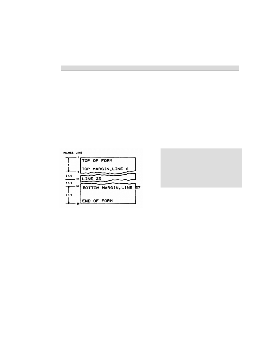
BASIC Programming Example for Skip to Channel
This is a sample program showing the use of the skip-to-channel
command. It makes use of the previously loaded EVFU program.
PROGRAM INSTRUCTION
REMARKS
10 WIDTH “LPT1:”,255
Required by some BASIC languages to avoid
auto LF at column 80
20 LPRINT CHR$(27)”[0;1!p”;
Go to top of form (channel 1)
30 LPRINT “TOP OF FORM”;
Print the indicated words
40 LPRINT CHR$(27)”[0;3!p”;
Go to channel 3
50 LPRINT “LINE 6”;
Print the indicated words
60 LPRINT CHR$(27)”[0;4!p”;
Go to channel 4
70 LPRINT “LINE 25”;
Print the indicated words
80 LPRINT CHR$(27)”[0;5!p”;
Go to channel 5
90 LPRINT “LINE 57”;
Print the indicated words
100 LPRINT CHR$(27)”0;8!p”;
Go to channel 8
110 LPRINT “END OF FORM”;
Print the indicated words
120 END
NOTE
Establish Top of Form locally before
printing out forms. When executing
the program, paper will slew to the
top of the next form before
beginning to print.

ANSI Emulation
GEK-99???
36
BARCODES
Thirteen different styles of barcodes and POSTNET are available.
Each style (except POSTNET) can be rotated 90, 180, or 270 degrees
and printed with or without a human-readable line (HRL). The
barcode symbol size and density are also adjustable.
Entering and Exiting Barcodes
Before the printer can print input data as barcode symbols. The
barcode mode must be both selected and activated. There are two
ways for this to be accomplished depending on the setting of printer
option 1 for both 4800 and 4410 ANSI emulation.
Printer option 1 is used to enable the SI (shift in) and SO (shift out)
ASCII codes to activate and deactivate special mode functions. In this
case, the special mode function is barcodes. With option 1 enabled,
code SO will turn on or activate the barcode mode. SI will turn
barcodes off.
ANSI 4800/4410 Strap 1 OUT
Enter the barcode mode of printing with the following control
sequence sent by the host. (See Appendix G for strapping options.)
ESC [ 3 t
LPRINT CHR$(27)*."[3t";
Data sent after the above sequence is interpreted and printed as
barcodes.
Exit the barcode mode using:
ESC [ 0 t
LPRINT CHR$(27);"[0t";
ANSI 4800/4410 Strap 1 IN
(See Appendix G for strapping options.)
ESC [ 3 t
LPRINT CHR$(27);"[3t";
Selects the barcode special mode.
SO
LPRINT CHR$(14);
Activates barcodes and prints all received data as barcodes. (Only
after it has been selected by ESC[3t above.)
NOTE
Control sequences given in the following text show the proper
syntax needed from the host. The second line has examples of
code written in the BASIC program language.
GEK-?????
5000 Series Programmer’s Manual
37
SI
LPRINT CHR$15);
Deactivates barcodes and allows printing of normal text.
ESC[0t
LPRINT CHR$(27);"[0t";
Deselects barcodes.
When an ESC[0t is received before the SI code, barcodes are both
deactivated and deselected.
Setting Barcode Parameters
Select the style, height, spacing, orientation, and print density for the
barcode using the following escape sequence. The second line in the
example (written in BASIC) shows the parameters that are the default
values for the printer.
ESC[p1;p2;p3;p4;p5;p6.p7;p8;p9;p10)
LPRINT CHR$(27);"[4;9;1;2;6;2;6;2;0;0}";
p1: Style
0
Interleaved 2 of 5
10
Codabar b/n
1
(Reserved for future use)
11
Codabar c/*
2
(Reserved for future use)
12
Codabar d/e
3
(Reserved for future use)
13
UPC-A
4
Code 3 of 9 (default)
14
UPC-E
5
EAN-8
15
Code 93
6
EAN-13
16
Code 128 (A, B, C)
7
Code 11
17
(Reserved for future use)
8
(Reserved for future use)
18
(Reserved for future use)
9
Codabar a/t
50
POSTNET (see note)
NOTE
When using POSTNET, parameters p2 through p10 are
invalid. If these parameters are changed, they will be
retained in memory and will affect other styles if selected.
See Appendix F for more information on POSTNET.

ANSI Emulation
GEK-99???
38
Barcode Dimensions
p2
Barcode height in 1/12-inch increments
Minimum:
1=l/12 inch
Maximum:
120=10 inches
Default:
9=9/12 inch (3 / 4 inch)
Human-readable line is not included in height.
p3
Human-readable line
0=Do not print human-readable line
1=Print human-readable line (default)
p4
Narrow bar width, number x 1/120 inch
Default:
2 (2/120 inch, approximately .017 inch)
Range:
2, 4, 6, . . . 126
p5*
Wide bar width, number x 1/120 inch
Default:
6 (6/120 inch, approximately . 050 inch)
Range:
2, 4, 6, . . . 254
p6
Narrow space width, number x 1/120 inch
Default:
2 (2/120 inch, approximately . 017 inch)
Range:
2. 4, 6, . . .126
p7*
Wide space width, number x 1/120 inch
Default:
6 (6/120 Inch. approximately .050 inch)
Range:
2, 4, 6, . . . 254
p8*
Intercharacter space width, number x: 1/120 inch
Default:
2 (2/120 inch, approximately . 017 inch)
Range:
2, 4, 6 . . . 126
* Parameters p5, p7, and p8 are not programmable in some
barcode styles since they are generated from other parameters.
NOTE
The following dimensions are for barcodes printed at 0 and 180
degrees rotation. Barcodes printed at 90 or 270 degrees rotation
will be compressed by a 6:5 ratio due to the difference in size of
the horizontal and vertical grids.

GEK-?????
5000 Series Programmer’s Manual
39
p9
Barcode rotation and human-readable line (HRL) font
style (if used).
0
No rotation - use currently selected font style, cpi, and
lpi. This is the default setting.
1
No rotation - use special HRL font.
2
90-degree rotation use special HRL font
3
180-degree rotation use special FIRL font.
4
270-degree rotation use special HRL font.
p 10 Horizontal print density
0
60 dpi horizontal by 144 dpi vertical print density
1
120 dpi horizontal by 144 dpi vertical print density
Default for barcode styles 5, 6, 13, and 14 is 120 dpi.
Default for all other styles is 60 dpi.
Barcodes printed at 90 or 270 degrees rotation will print at the
same speed (120 x 144) regardless of the selected horizontal
density.
A missing parameter
will
leave the corresponding value
unchanged.
A zero parameter value for p2–p8 will cause the default value
to be selected.
Use semicolons as place holders when changing parameters.
LPRINT CHR$(27);"[;;;;;;;;;1}" Changes only parameter 10.
LPRINT CHR$(27);"15;;0}"
Changes only parameters 1 and 3.
LPRINT CHR$(27);"[16}"
Changes only the style of the barcode.
If no changes are made to the parameters of the barcode, the
printer will use the following factory-set values.
IMPORTANT
If no parameters have previously been entered, then the
factory default values will be used. If previous values have
been sent from the host. these values will prevail until
changed by the host or the printer is reset using the
initialization switch.

ANSI Emulation
GEK-99???
40
Default Barcode Characteristics
p1=4 Code 39
p2=9 3/4 inch height
p3=1 Human-readable line printed
p4=2 Narrow bar width 1/60 inch
p5=6 Wide bar width 1/20 inch
p6=2 Narrow space width 1/60 inch
p7=6 Wide space width 1/20 inch
p8=2 Intercharacter space width 1/60 inch
p9=0 No rotation, use currently selected font
p10=0 Horizontal print density 60 dpi
Human-Readable Line (HRL)
The human-readable line is printed 0. 10 inch below the bar code
symbol. The height of the HRL and the 0.10 inch space are not
included in the bar code height parameter (p2).
A diamond symbol appearing in the human-readable line indicates
one of the following conditions:
• Margin overrun. The data to be printed exceeds the available space
remaining inside the programmed margins.
• The DEL character has been received while printing in a bar code
style that permits the use of all 128 ASCH characters.
• An invalid character has been received. An example of this would be
a letter "A" sent to the printer while printing a style 5 bar code. Style
5 (EAN-8) only accepts the digits 0-9.
Font Styles and Enhancements
Non-rotated bar codes can be printed with an HRL in any of the fonts
available to the printer.
If enhancements are desired (e.g., bold, underline, or expanded) the
HRL must be printed using the normal text mode. Print the bar code
symbol(s) without the HRL first. Exit the bar code mode and print the
HRL using the normal text mode with enhancements.
Rotated bar codes use a special font for the human-readable line.
Spacing and Bar Code Editing Aids
There is a 0.25-inch space called a quiet zone at the beginning and
end of every bar code. As a result, the minimum distance between
two horizontal bar codes will be 0.50 inch.
Most bar code styles accept commas. spaces, and horizontal tabs as
delimiters to separate bar codes. A comma will add no additional
space between bar codes, so the separation will be the width of the
quiet zone or 0.50 inch. A space character will add 0.10 inch to the
quiet zone for a total of 0.60-inch separation. A horizontal tab will
add the appropriate number of empty spaces to go to the next tab.

GEK-?????
5000 Series Programmer’s Manual
41
Bar Code Readability Statement
The following information is provided to ensure that the best results
are obtained from your printed bar codes.
Use bar code readers designed to operate in the visible light
frequency range. Optional infrared-readable ribbon cartridges are
available.
Use bar code readers designed to read medium- or low-density bar
code symbols. Avoid readers with apertures less than 7 mils (. 007
inch or . 18mm).
Using bar code size parameters smaller than the default settings may
produce unacceptable results.
ANSI Emulation
GEK-99???
42
Bar Code Program Examples
The following program examples are provided to help you become
familiar with the bar code escape sequences. The programs are
written in BASIC and printed using the LUST command. All bar
codes are actual size.
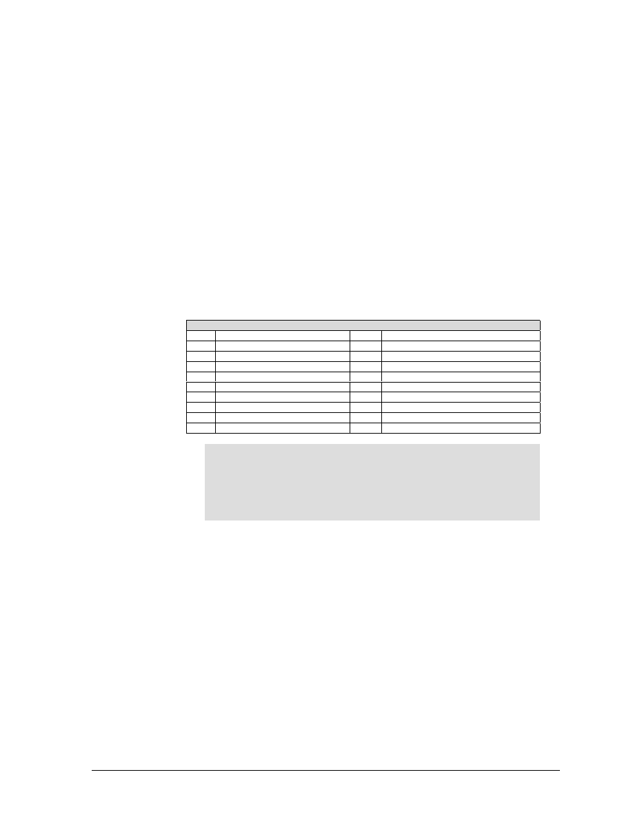
Test Program
This is the minimum code needed to print a bar code. Use it to test
the printer's ability to print bar codes when more complicated
programs are not producing results.
Line 10 turns on the bar code mode. line 20 contains the data to be
printed as a bar code symbol, and line 30 turns off the bar code
mode.
10 LPRINT CHR$(27); "[3t";
20 LPRINT "1234567890";
30 LPRINT CHRS(27); "[0t";
Error Symbol
This example shows the error symbol in the HRL and the error
pattern in the symbol. The error pattern causes the entire symbol to
be rejected by the bar code reader.
The error was caused by the lowercase "a" being inserted into the
data. The default style, Code 3 of 9. accepts only uppercase A-Z, the
numbers 0-9, and the characters
10 LPRINT CHR$(27); "[3t";
20 LPRINT "1a34567890";
30 LPRINT CHR$(27); "[0t"
GEK-?????
5000 Series Programmer’s Manual
43
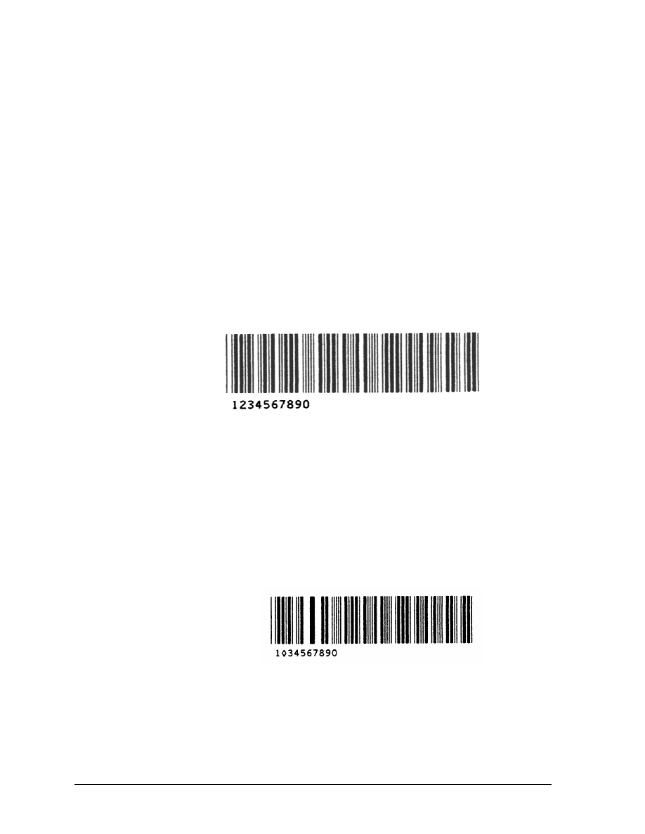
Changing Parameters
This example changes the style p1, height p2, and the HRL font p9 of
the bar code. Notice that semicolons are used as place holders for the
parameters not being changed.
Line 10 - change style to Code 128, change height to 1/4" (3/12").
and use the special HRL font.
10 LPRINT CHR$(27);
20 LPRINT CHR$(27); "[3t";
30 LPRINT "1234567890";
40 LPRINT CHR$(27); "[0t"
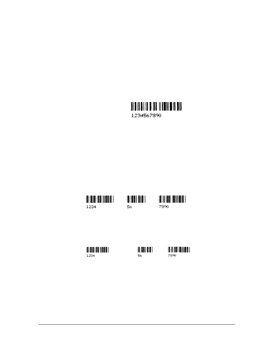
Commas and Spaces as Delimiters
When a comma delimiter is used to separate bar codes, no additional
space Is added to the quiet zones. Since the ending .25-inch quiet
zone of one bar code symbol meets the beginning quiet zone of the
next bar code, a total of . 50 inch separates the two. Style 7 (line 5) is
used for these examples since Code 11 uses both spaces and commas
as delimiters.
10 LPRINT CHR$27); "[7}";
20 LPRINT CHR$27); "[3t";
30 LPRINT "1234,56,7890";
40 LPRINT CHR$27); "0t"
When spaces are used as delimiters, an additional 1 inch is added to
the quiet zones. Note that multiple spaces can be used.
10 LPRINT CHR$27); "[3t"
20 LPRINT "1234567890";
30 LPRINT CHR$27); "[0t"
ANSI Emulation
GEK-99???
44
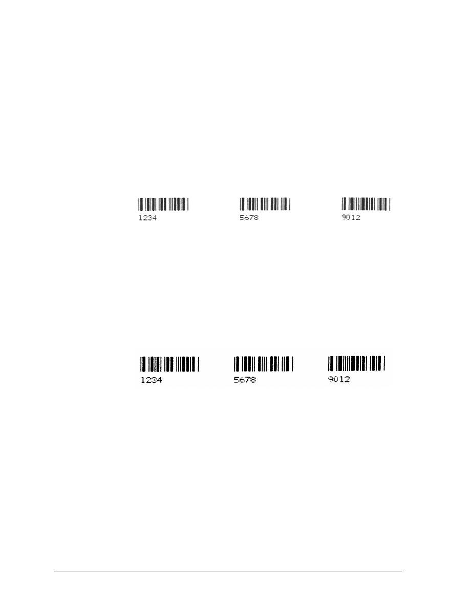
Horizontal Spacing
Use horizontal tabs for spacing bar code symbols across the page.
Line 10 sets horizontal tabs at 1440 and 2880 decipoints (2 and 4
inches). The HT codes in lines 40 and 60 cause a jump to the next
tab.
10 LPRINT CHR$27); "[1440;2880;u";
20 LPRINT CHR$27); "[3t";
30 LPRINT "1234";
40 LPRINT CHR$(9);
50 LPRINT "5678";
60 LPRINT CHR$(9);
70 LPRINT "9012";
80 LPRINT CHR$27); "[0t"
When no horizontal tabs are set, an HT code acts as a space. adding
0.1 inch to the separation. Total separation is 0.6 inch when the HT
is added to the quiet zones.
Line 10 clears all previously set horizontal tabs for this example.
10 LPRINT CHR$(27); "[3g";
20 LPRINT CHR$(27); "[3t";
30 LPRINT "1234";
40 LPRINT CHR$(9);
50 LPRINT "5678";
60 LPRINT CHR$(9);
70 LPRINT "9012";
80 LPRINT CHR$(27); "[0t"
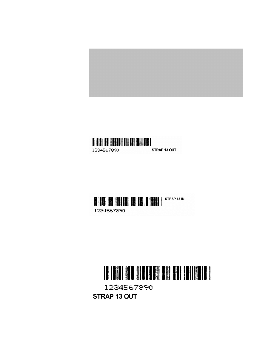
Printer Option Strap 13, Group 2 IN
Printer control strap 13 is used for positioning the paper after
printing a bar code. Strap 13 IN sets the paper to the top of the bar
code after printing; strap 13 OUT leaves the paper position as is after
printing
a
bar code.
The state of strap 13 can be checked and changed using the
configuration menu.
In the following examples, lines 10-30 print the bar code symbol and
line 40 adds a line of text to be printed.
Examples 1 and 2 show the effect strap 13 has on the position of the
text.
In example 3, the semicolon at the end of line 30 has been deleted to
show that strap 13 only affects the same horizontal zone that the bar
GEK-?????
5000 Series Programmer’s Manual
45
code occupies. The semicolon in BASIC Is used to suppress a LF/CR
after an LPRINT statement.
EXAMPLE 1: Strap 13 OUT
10 LPRINT CHR$(27); "[3t";
20 LPRINT "1234567890";
30 LPRINT CHR$(27); "[0t";
40 LPRINT "STRAP 13 OUT"
EXAMPLE 2: Strap 13 IN
10 LPRINT CHR$(27); "[3t";
20 LPRINT "1234567890";
30 LPRINT CHR$(27); "[0t";
40 LPRINT "STRAP 13 IN"
EXAMPLE 3: Strap 13 OUT with no suppression of
LF/CR on line 30
10 LPRINT CHR$(27); "[3t";
20 LPRINT "1234567890";
30 LPRINT CHR$(27); "[0t"
40 LPRINT "STRAP 13 OUT"
IMPORTANT
Strap 13 is only effective after exiting the bar code mode. As in
the printout above, printing multiple bar codes without exiting
(line 80 above) causes all the bar codes to be printed in the
same horizontal area of the paper regardless of the condition of
strap 13. Also, some form of printable data must be on the line
before a paper move command (see line 40 in the examples); if
not, the paper will not backup to the top of the bar code.

ANSI Emulation
GEK-99???
46
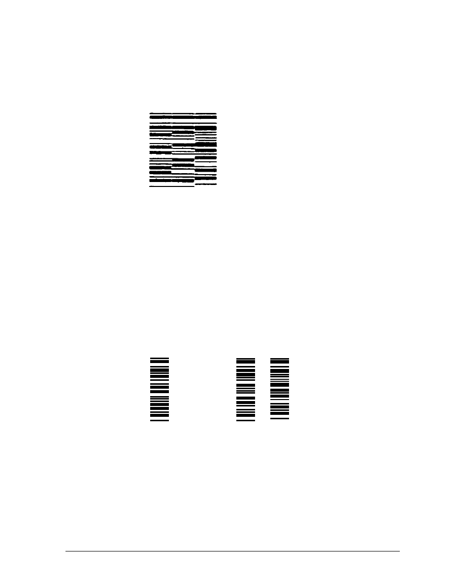
Vertical Bar Codes
Line 10 sets parameter p9 for 90-degree rotation using the special
font for the HRL.
Line 20 turns on the bar code mode.
Line 30 is the data to be printed as a bar code symbol.
Line 40 turns off the bar code mode.
10 LPRINT CHR$(27); "[;;;;;;;;2}";
20 LPRINT CHR$(27); "[3t";
30 LPRINT "12345";
40 LPRINT CHR$(27); "[0t"
Commas and spaces used as delimiters serve the same function as in
horizontal bar codes. However, the quiet zones rotate with the
symbol, leaving almost no horizontal separation between bar codes
on the same line.
In the following examples, line 10 is used
to print or
inhibit the
printing of the HRL (p3).
COMMAS: With HRL
10 LPRINT CHR$(27);
20 LPRINT CHR$(27); "[3t";
30 LPRINT "1234,5678,9012";
40 LPRINT CHR$(27); "[0t"
GEK-?????
5000 Series Programmer’s Manual
47
COMMAS: Without HRL
10 LPRINT CHR$(27); "[;;0)";
20 LPRINT CHR$(27); "[3t";
30 LPRINT "1234,5678,9012";
40 LPRINT CHR$(27); "10t"
SPACES: With HRL
10 LPRINT CHR$(27);
20 LPRINT CHR$(27); "[3t";
30 LPRINT "1234
1
5678 9012";
40 LPRINT CHR$(27); "[0t"
SPACES: Without HRL
10 LPRINT CHR$(27); "[;;0)";
20 LPRINT CHR$(27); "[3t";
30 LPRINT "1234
5678 9012";
40 LPRINT CHR$(27); "[0t"
ANSI Emulation
GEK-99???
48
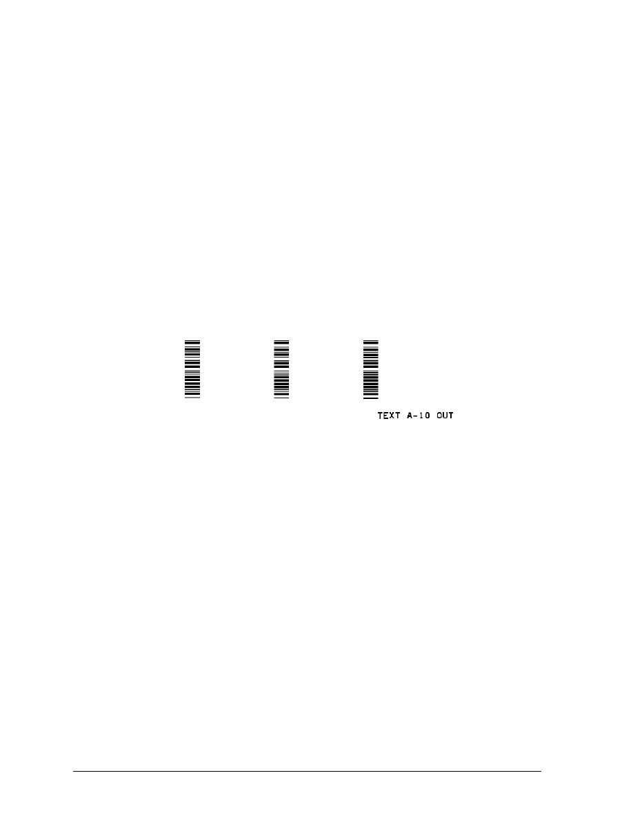
HORIZONTAL TABS
Line 10 sets horizontal tab stops at 1080 and 2160 decipoints (1.
5 and 3 inches).
Lines 40 and 60 are ITT codes that cause a jump to the next tab
stop.
Line 90 is a line of text to show positioning on the paper. The vertical
separation between the bar code symbol and the text "A10 OUT" is
the ending quiet zone.
10 LPRINT CHR$(27); "[1080;2160;u";
20 LPRINT CHR$(27); "[3t";
30 LPRINT "12345";
40 LPRINT CHR$(9);
50 LPRINT "12345";
60 LPRINT CHR$(9);
70 LPRINT "12345";
80 LPRINT CHR$(27); "[0t";
90 LPRINT "TEXT A-10 OUT"
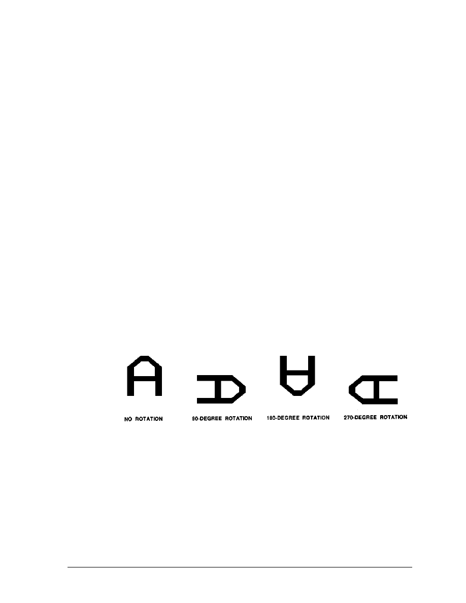
GEK-?????
5000 Series Programmer’s Manual
49
OVERSIZE CHARACTER FONT
The oversize font is composed of special block-style characters that
can be expanded 156 times the size of standard fonts. This will
produce letters up to 15.25-inches (388mm) high by 13 inches
(330mm) wide. Oversize characters can be rotated 90, 180, or 270
degrees.
Do not confuse oversize characters with expanded characters. The
expanded character feature, (standard in your printer), expands all
existing fonts up to 8 times the normal size. These characters are not
rotatable.
The oversize character feature works with the ANSI protocol.
Entering and Exiting Oversize
The following sequences are used to enter, rotate, and exit oversize
printing:
ESC [ 0 |
Exit oversize printing.
ESC [ 1 |
Select oversize font with no rotation.
ESC [ 2 |
Select oversize font with 90-degree rotation.
ESC [ 3 |
Select oversize font with 180-degree rotation.
ESC [ 4 |
Select oversize font with 270-degree rotation.
LPRINT CHR$(27);"[0|
";
or
LPRINT CHR$(27);"[0|";CHR$(124);
Once oversize has been turned on, it will remain on until an
ESC [ 0 | sequence is used to turned it off. It does not turn off due to
line terminators (CR and LF).
Selecting Size
ESC [p1;p2 B is the sequence used to set the vertical (p1) and
horizontal (p2) size of the oversize characters. A p1 value of 300
would increase the vertical size of the character 300% or 3 times.
The last two digits of each parameter are necessary to comply with
the ANSI standard, but are ignored by the printer. Using the above
example for p1, any three-digit number starting with 3 (300-399) will
be interpreted as 3 times normal size. Likewise, 400-499 equals 4
times, 1200-1299 equals a 12-times increase in size, and so on. The

ANSI Emulation
GEK-99???
50
maximum size is 15600;15600 (156 times) and the minimum or
default is 200;200 (2 times).
Since this same sequence is used to change size in the expanded
mode, the parameters must be cleared to normal size,
ESC [100;100 B, to prevent entering expanded mode when oversize is
turned off.
Mnemonic:
ESC [ p1; p2 B
Decimal:
27 91 p1 59 p2 66
Hex:
1B 5B p1H 3B p2 42
BASIC:
CHR$(27);"[";p1;";";p2;"B";
Size Parameters for Rotation
The p1 and p2 size parameters are always relative to a rotation angle
of zero degrees. That is, the characters are expanded first and then
rotated.
Spacing Between Characters
For non-rotated characters and characters rotated 180 degrees, the
horizontal spacing between characters is 1/60-inch times the p2
parameter.
For characters rotated 90 or 270 degrees, the horizontal spacing
between characters is 3/60-inch times the p1 parameter.
Vertical spacing is dependent on vertical paper move commands (LF,
CR, VPR, etc.), the state of menu option GenPrtOpts/Group 2/Strap
13, and the character size and line spacing currently in effect.
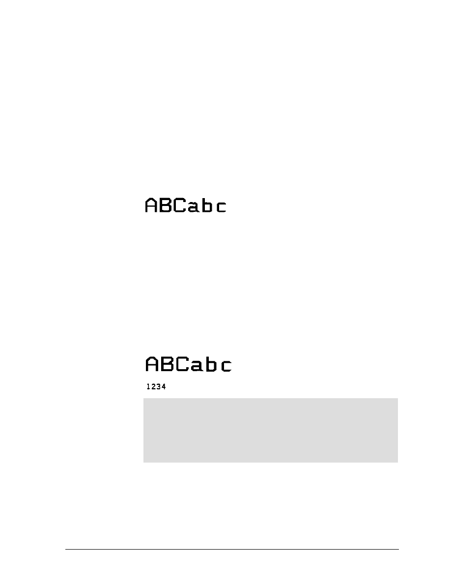
GEK-?????
5000 Series Programmer’s Manual
51
Sample Programs
Example 1
The first example shows the code used to print oversize.
Line 10 sets the size to X3 vertical (V) and X3 horizontal (H). Line 20
enters oversize printing with
no rotation. Line 30 is the data to be
printed. Line 40 exits oversize printing. Line 50 returns the size
parameters to X 1 V - X 1 H.
10 LPRINT CHR$(27); "[300;300B";
20 LPRINT CHR$(27); "[1|";
30 LPRINT "ABCabc";
40 LPRINT CHR$(27); "[0|";
50 LPRINT CHR$(27); "[100;100B"
Example 2
The next two examples demonstrate the importance of setting the size
parameters back to X1 V - X1 H after printing oversize. This is the
same program used in Example 1 with an additional line added.
Line 60 prints 1234 in the currently selected font.
10 LPRINT CHR$(27); "[300;300 B";
20 LPRINT CHR$(27); "El:";
30 LPRINT "ABCabc"
40 LPRINT CHR$(27); "CO:";
50 LPRINT CHR$(27); "[100;100 B"
60 LPRINT "1234"
NOTE
In BASIC, LPRINT statements automatically generate an LF/CR
at the end of the line unless suppressed by a semicolon. Since
line 30 does not end with a semicolon, an LF/CR occurred at
the lpi in effect (still in oversize). This accounts for the vertical
distance between the ABCabc line and the 1234 line.
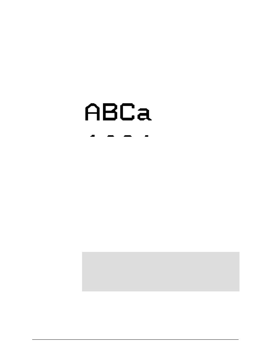
ANSI Emulation
GEK-99???
52
Example 3: Showing the Importance of Resetting
Scaling Factors
If line 50, which sets the size to X1 V and X1 H. is removed, the data
printed in line 60 is now subject to the expanded mode of printing.
Notice (below) that the 1234 printed line is expanded vertically by X3
10 LPRINT CHR$(27); "[300;300 B";
20 LPRINT CHR$(27); "El:";
30 LPRINT "ABCabc";
40 LPRINT CHR$(27); "[0:"
60 LPRINT "1234"
Printer Control Strap GenPrtOpts/Group 2/Strap 13
This printer control strap is used for positioning the paper after
printing oversize characters. When this strap is set to IN, the paper is
positioned at the top of the oversize character after printing; when set
to OUT, the paper position remains as is after printing oversize.
The state of the printer strap can be checked and changed using the
configuration menu.
In the following examples:
Lines 10-30 print oversize characters at X3.
Line 50 changes the oversize to X4 V by X6 H.
Lines 70-80 print oversize and exits.
Line 90 returns the parameters to X1 to prevent expanded
printing.
Lines 100-110 print normal text to show the effect that strap 13
has on positioning.
IMPORTANT
Line spacing was set back to normal (6 lpi) when normal text
was selected in line 90. When strap 13 is IN and the paper
position returns to the top of oversize, vertical moves (CR, LF,
VPA, VPR) must be used to move the paper to prevent
overprinting on the oversize characters.
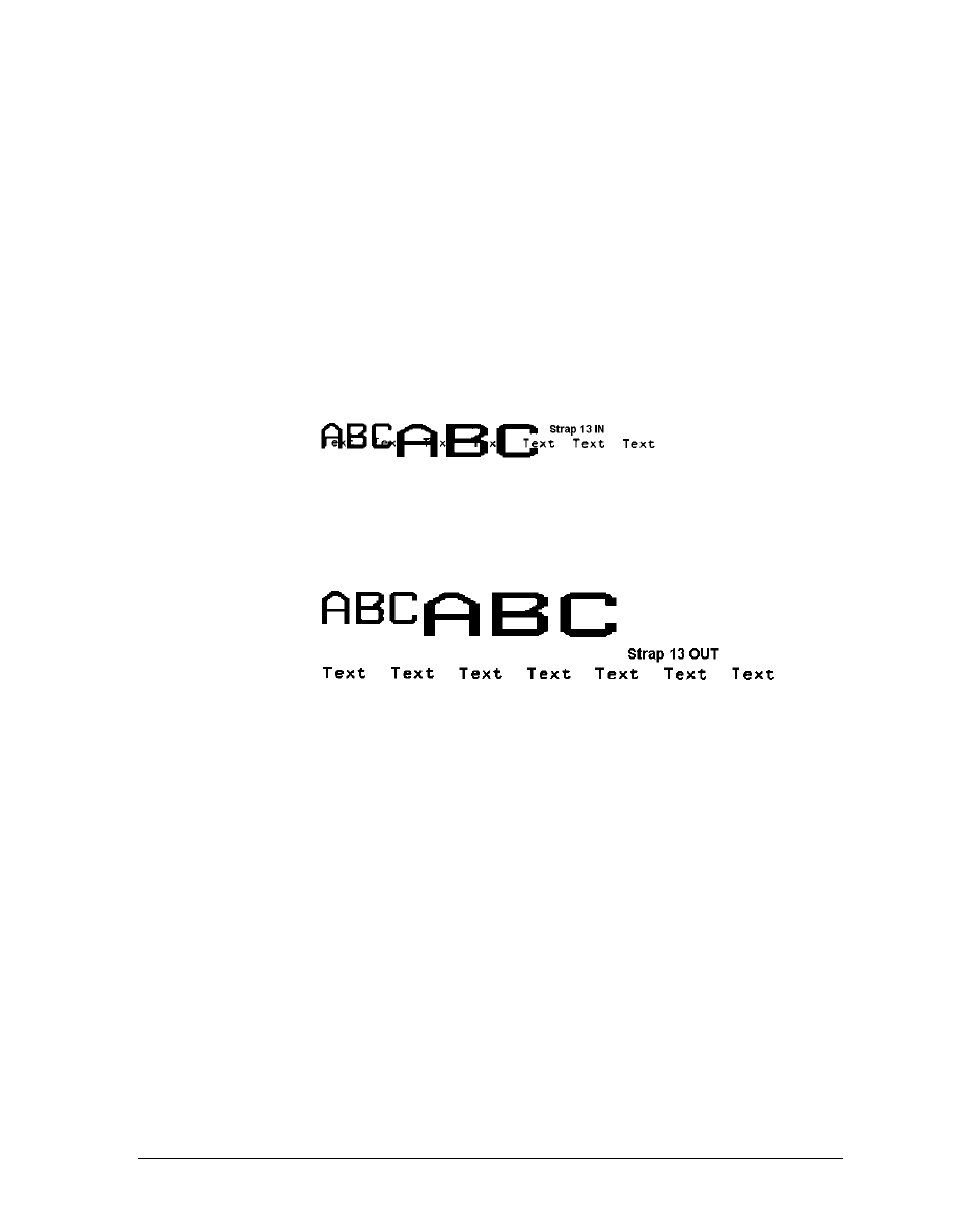
GEK-?????
5000 Series Programmer’s Manual
53
Example 4: GenPtrOpts | Group 2 Strap 13 IN
The oversized characters and the first line of normal printing are
aligned at the first print line. The second line of normal printing (Text
Text Text . . .) started printing one line below Strap 13 IN and
overprints the oversized text.
100 LPRINT CHR$(27);"[300;300B";
110 LPRINT CHR$(27);"[1|";
120 LPRINT "ABC";
130 LPRINT CHR$(27);"[400;600B";
140 LPRINT "ABC";
150 LPRINT CHR$(27);"[0|";
160 LPRINT CHR$(27);"[100;100B";
170 LPRINT "Strap 13 IN";
180 LPRINT "Text Text Text Text Text Text Text"
Example 5: GenPtrOpts | Group 2 Strap 13 OUT
Paper motion is not returned after printing oversized characters.
Document Outline
- ANSI EMULATION
- CONTROL CODE AND ESCAPE SEQUENCE ACTIVITY LEVELS
- CONTROL CODE DEFINITIONS
- ESCAPE SEQUENCE DIRECTORY
- ANSI ESCAPE SEQUENCE CATEGORIES
- GRAPHICS
- ELECTRONIC VERTICAL FORMAT UNIT ˚ EVFU
- BARCODES
- Entering and Exiting Barcodes
- ANSI 4800/4410 Strap 1 OUT
- ANSI 4800/4410 Strap 1 IN
- Setting Barcode Parameters
- Human˚Readable Line (HRL)
- Font Styles and Enhancements
- Spacing and Bar Code Editing Aids
- Bar Code Readability Statement
- Bar Code Program Examples
- Test Program
- Error Symbol
- Changing Parameters
- Commas and Spaces as Delimiters
- Horizontal Spacing
- Printer Option Strap 13, Group 2 IN
- Vertical Bar Codes
- OVERSIZE CHARACTER FONT
Wyszukiwarka
Podobne podstrony:
CARPROG BMW Key programmer manual
CARPROG Motorola HC12 programmer manual
CARPROG MB key programmer manual
CARPROG Motorola HC05 programmer manual
KG 659E Updated version Programming manual
fanuc cnc program manual gcode
PM0056 STM32F10xxx Cortex M3 programming manual
CARPROG Motorola HC08 programmer manual
CARPROG Motorola HC11 programmer manual
CARPROG BMW Key programmer manual
DoD Nuclear Weapon System Safety Program Manual
Sole Control Sc230 Sc240 Sc241 Remote Programming Manual
więcej podobnych podstron