PARKING BRAKE
H14.00-20.00XM (H360-450H) [A214];
H16.00-18.00XM-12EC (H400-450H-EC5-6) [A214];
RS45-27CH, RS45-30CH, RS46-33CH, RS46-36CH,
RS45-27IH, RS46-30IH, RS46-33IH [A222]; H20.00-32.00F,
H28.00F-16CH (H440, H550, H620, H700F, FS) [E008];
H36.00-48.00E (H800-1050E) [D117];
H36.00-48.00E-16CH (H800-1050E-16CH) [D117]
PART NO. 1531821
1800 SRM 1037

SAFETY PRECAUTIONS
MAINTENANCE AND REPAIR
• When lifting parts or assemblies, make sure all slings, chains, or cables are correctly
fastened, and that the load being lifted is balanced. Make sure the crane, cables, and
chains have the capacity to support the weight of the load.
• Do not lift heavy parts by hand, use a lifting mechanism.
• Wear safety glasses.
• DISCONNECT THE BATTERY CONNECTOR before doing any maintenance or repair
on electric lift trucks. Disconnect the battery ground cable on internal combustion lift
trucks.
• Always use correct blocks to prevent the unit from rolling or falling. See HOW TO PUT
THE LIFT TRUCK ON BLOCKS in the Operating Manual or the Periodic Mainte-
nance section.
• Keep the unit clean and the working area clean and orderly.
• Use the correct tools for the job.
• Keep the tools clean and in good condition.
• Always use HYSTER APPROVED parts when making repairs. Replacement parts
must meet or exceed the specifications of the original equipment manufacturer.
• Make sure all nuts, bolts, snap rings, and other fastening devices are removed before
using force to remove parts.
• Always fasten a DO NOT OPERATE tag to the controls of the unit when making repairs,
or if the unit needs repairs.
• Be sure to follow the WARNING and CAUTION notes in the instructions.
• Gasoline, Liquid Petroleum Gas (LPG), Compressed Natural Gas (CNG), and Diesel fuel
are flammable. Be sure to follow the necessary safety precautions when handling these
fuels and when working on these fuel systems.
• Batteries generate flammable gas when they are being charged. Keep fire and sparks
away from the area. Make sure the area is well ventilated.
NOTE: The following symbols and words indicate safety information in this
manual:
WARNING
Indicates a condition that can cause immediate death or injury!
CAUTION
Indicates a condition that can cause property damage!

Parking Brake
Table of Contents
TABLE OF CONTENTS
General ...............................................................................................................................................................
Description and Operation ................................................................................................................................
Parking Brake Caliper Repair ..........................................................................................................................
Release Brake Manually ...............................................................................................................................
Hydraulic Pressure Available ...................................................................................................................
Hydraulic Pressure not Available.............................................................................................................
Remove ...........................................................................................................................................................
Disassemble ...................................................................................................................................................
Clean ..............................................................................................................................................................
Inspect ............................................................................................................................................................
Linings .......................................................................................................................................................
Disc.............................................................................................................................................................
Caliper Parts .............................................................................................................................................
Assemble ........................................................................................................................................................
Install .............................................................................................................................................................
Bleed Brakes ..................................................................................................................................................
Adjust .............................................................................................................................................................
Test .................................................................................................................................................................
Specifications......................................................................................................................................................
Troubleshooting..................................................................................................................................................
This section is for the following models:
H14.00-20.00XM (H360-450H) [A214];
H16.00-18.00XM-12EC (H400-450H-EC5-6) [A214];
RS45-27CH, RS45-30CH, RS46-33CH, RS46-36CH, RS45-27IH,
RS46-30IH, RS46-33IH [A222];
H20.00-32.00F, H28.00F-16CH (H440, H550, H620, H700F, FS) [E008];
H36.00-48.00E (H800-1050E) [D117];
H36.00-48.00E-16CH (H800-1050E-16CH) [D117]
©2005 HYSTER COMPANY
i

"THE
QUALITY
KEEPERS"
HYSTER
APPROVED
PARTS
1800 SRM 1037
Description and Operation
General
The main components of the parking brake system
are:
• Parking brake switch
• Solenoid valve
• Parking brake caliper
This parking brake is for use on hydraulic brake sys-
tems only.
Description and Operation
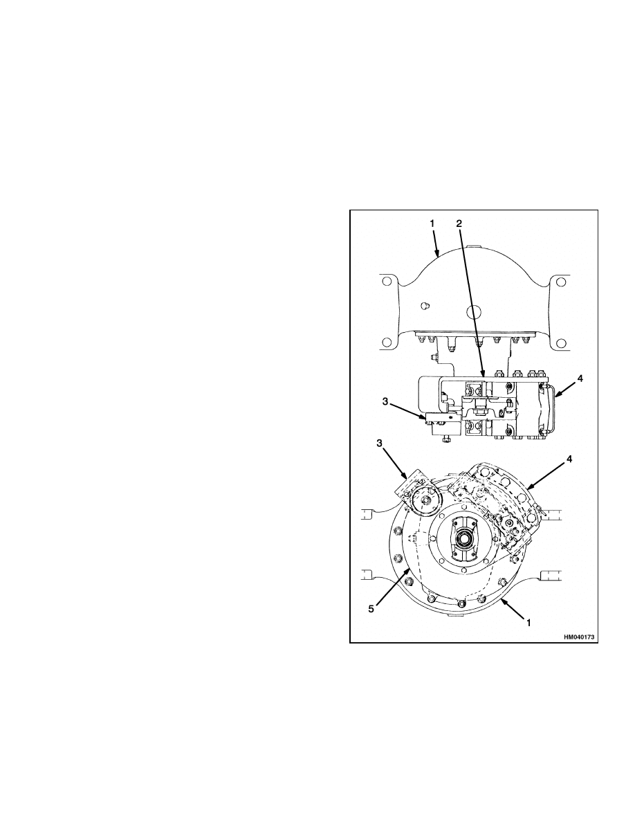
The parking brake system uses a disc brake that
is installed at the rear of the differential housing.
See Figure 1 for typical system configuration. The
spring-applied caliper is installed on the differential
housing. The brake rotor is installed on the pinion
shaft.
When hydraulic pressure is released, the springs in-
side the brake expand to force the piston and lin-
ings against the disc. To release the brake, hydraulic
pressure must be applied to release the springs. The
brake can be released manually if hydraulic pressure
is not available.
The operation of the parking brake is controlled by
a solenoid valve for the parking brake. The sole-
noid is operated by a switch on the instrument panel.
The solenoid is normally energized during operation
for oil pressure to compress the spring to release the
parking brake.
1.
DIFFERENTIAL
2.
BRAKE ASSEMBLIES AND MOUNT
3.
PARKING BRAKE CALIPER
4.
AUXILIARY BRAKE CALIPER
5.
ROTOR
Figure 1. Auxiliary and Parking Brake
Assemblies
1
Parking Brake Caliper Repair
1800 SRM 1037
Parking Brake Caliper Repair
RELEASE BRAKE MANUALLY
Hydraulic Pressure Available
WARNING
To prevent serious eye injury, always wear safe
eye protection when doing maintenance or ser-
vice.
WARNING
If it is necessary to raise the vehicle to service
the parking brake, support the vehicle with
safety stands.
Do not work under a vehicle
supported only by jacks. Jacks can slip or fall
over and cause serious personal injury.
WARNING
Never try to turn or remove the spring cap
while hydraulic pressure is applied to the
brake. Turning the cap while pressure is ap-
plied can damage the O-ring seals and the
spring cap threads.
Removing the cap can
cause serious personal injury by the sudden
release of hydraulic pressure. Verify that the
nut is at the end of the stud before you place
the vehicle in service. If the nut is tightened
against the spring cap, the brake cannot be
applied and serious personal injury can result.
1.
Verify that the vehicle is on a level surface.
2.
Put blocks under the wheels not being serviced
to keep the vehicle from moving.
3.
Apply hydraulic pressure to release the brake.
NOTE: The manual release stud and nut have left-
hand threads.
4.
To lock the brake in the released position, remove
the cotter pin from the stud nut until it touches
the spring cap.
5.
Release the hydraulic pressure.
Hydraulic Pressure not Available
1.
Verify that the vehicle is on a level surface.
2.
Put blocks under the wheels not being serviced
to keep the vehicle from moving.
3.
Remove the cotter pin from the stud nut. Tighten
the nut against the spring cap and continue
tightening to manually retract the piston and
lining from the disc. Stop tightening when the
spring cap starts to turn.
REMOVE
1.
Verify that the vehicle is on a level surface.
2.
Put blocks under the wheels not being serviced
to keep the vehicle from moving.
WARNING
Before disconnecting any hydraulic lines, re-
lease pressure from the hydraulic circuit as fol-
lows:
a. Shut off the engine and completely lower
the carriage. Install blocks at the wheels to
prevent the lift truck from moving.
b. Operate the lift/lower lever and the brake
pedals until the hydraulic pressure is re-
leased.
WARNING
Brake linings can contain dangerous fibers.
Breathing the dust from these linings can
be a cancer or lung disease hazard.
Do not
make dust!
Do not clean brake parts with
compressed air or by brushing. Use vacuum
equipment approved for brake dust or follow
the cleaning procedure in this section. When
calipers are removed, do not make dust.
Do not sand, grind, chisel, hammer, or change
linings in any way that will make dust. Any
changes to linings must be done in a restricted
area with special ventilation. Protective cloth-
ing and a respirator must be used.
3.
Manually release the brakes using the proce-
dures described in Release Brake Manually.
4.
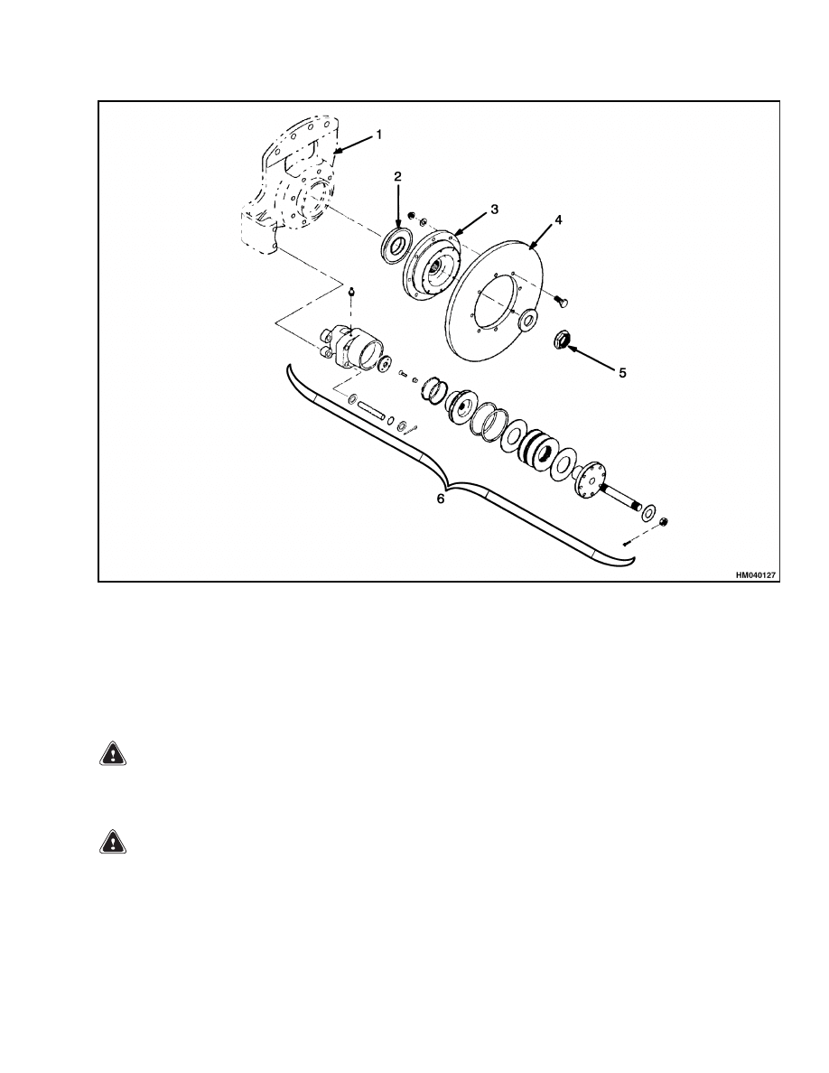
Disconnect the brake line from the caliper inlet.
Put plugs in the brake line and in the inlet to pre-
vent contamination of the system. See Figure 2.
5.
Remove the centering device if one is assembled
on the end of the caliper.
6.
Remove the caliper slide pin fasteners. Remove
slide pins.
2
1800 SRM 1037
Parking Brake Caliper Repair
1.
CALIPER MOUNT
2.
OIL SEAL
3.
ROTOR FLANGE
4.
ROTOR
5.
NUT AND WASHER
6.
CALIPER ASSEMBLY
Figure 2. Parking Brake Assembly
7.
Remove the caliper from the disc.
DISASSEMBLE
WARNING
To prevent serious eye injury, always wear safe
eye protection when doing maintenance or ser-
vice.
WARNING
If it is necessary to raise the vehicle to service
the parking brake, support the vehicle with
safety stands.
Do not work under a vehicle
supported only by jacks. Jacks can slip or fall
over and cause serious personal injury.
1.
Remove the inlet fitting and the O-ring from the
housing. Drain and discard the fluid. See Fig-
ure 3.
2.
Put a plug in the inlet to prevent contamination
of the housing.
3.
Remove lining fasteners. Remove linings by us-
ing a pry bar between the lining and piston or
housing.
3
Parking Brake Caliper Repair
1800 SRM 1037
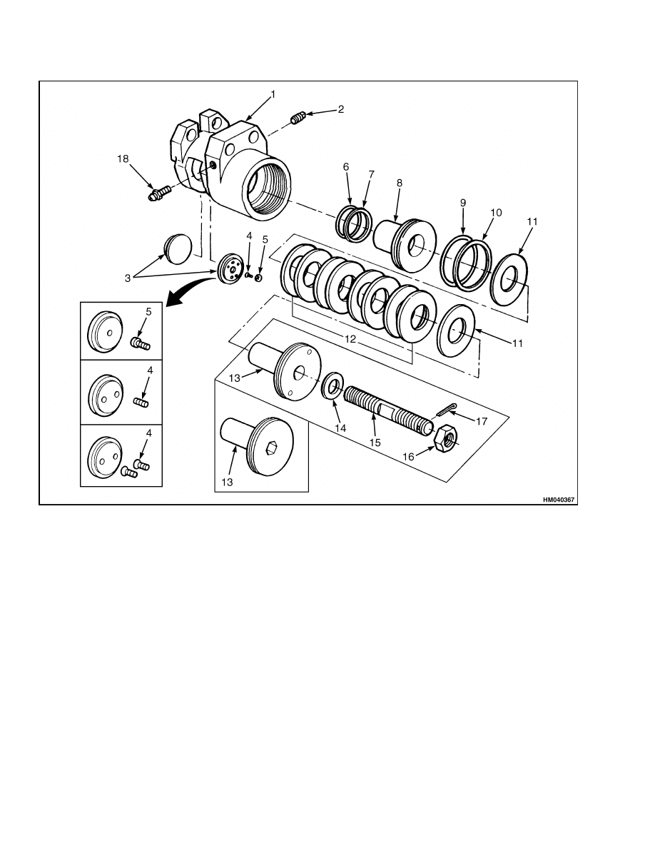
1.
HOUSING, 1 EA
2.
PLUG
3.
BRAKE LINING, 2 EA
4.
SCREW, 2 EA
5.
SNAP FASTENER, 2 EA
6.
BACKUP RING, 1 EA
7.
O-RING SEAL, 1 EA
8.
PISTON, 1 EA
9.
O-RING SEAL, 1 EA
10. BACKUP RING, 1 EA
11. FLAT WASHER, 2 EA
12. SPRING, 8 EA
13. SPRING CAP, 1 EA
14. WASHER, 1 EA
15. STUD, 1 EA
16. NUT, 1 EA
17. COTTER PIN, 1 EA
18. BLEEDER SCREW
Figure 3. Parking Brake Caliper Components
NOTE: The manual release stud and nut have left-
hand threads.
4.
If necessary, remove the pin and nut from the
manual release stud. Do not remove the washer
from around the stud unless the washer is loose
or damaged.
5.
Use a spanner wrench or an Allen wrench as re-
quired to remove the spring cap.
6.
Remove the washers and springs from inside the
caliper housing.
7.
Remove the piston through the hole for the
spring cap.
8.
If necessary, remove the setscrews or snaps if ei-
ther hold the linings to the piston and housing.
4
1800 SRM 1037
Parking Brake Caliper Repair
CAUTION
Use a wooden tool and vise with soft jaws in
the following steps to prevent damage to the
caliper piston or housing.
9.
Remove and discard the O-rings and backup
rings from the piston and housing.
NOTE: The piston has right-hand threads.
10. If necessary, hold the piston in a vise and remove
the stud from the piston.
CLEAN
WARNING
To prevent serious eye injury, always wear safe
eye protection when performing vehicle main-
tenance or service.
WARNING
To avoid personal injury when cleaning parts,
work in a well-ventilated area, wear protective
clothing (face shield or safety glasses and pro-
tective gloves), and follow chemical manufac-
turer’s recommendations for safe usage.
Solvent cleaners can be flammable, poisonous,
and cause burns. Examples of solvent clean-
ers are carbon tetrachloride, emulsion-type
cleaners, and petroleum-based cleaners.
To
avoid serious personal injury when using sol-
vent cleaners, carefully follow manufacturer’s
instructions and these procedures:
• Wear safe eye protection.
• Wear clothing that protects skin.
• Work in a well-ventilated area.
• Do not use gasoline or solvents that contain
gasoline. Gasoline can explode.
• Use hot solution tanks or alkaline solutions
correctly.
Carefully follow manufacturer’s
instructions.
CAUTION
Use only solvent cleaners to clean ground or
polished metal parts. Hot solution tanks or wa-
ter and alkaline solutions will damage these
parts. Isopropyl alcohol can be used for this
purpose.
1.
Use solvent cleaners to clean all metal parts that
have a ground or polished surface. Metal sur-
faces that have a rough surface can be cleaned
with solvent cleaners or alkaline solutions.
2.
Clean all threads and fittings with a wire brush.
3.
Clean all parts not made of metal with soap and
water.
4.
Scrape off all mud and dirt from the brake lin-
ings. Discard all linings contaminated with oil
or grease.
5.
Dry all parts with clean paper or rags.
6.
Apply hydraulic fluid used in the system to the
clean parts that are to be assembled. Do not ap-
ply fluid to the linings or disc.
INSPECT
Linings
CAUTION
Always replace both linings. If only one lining
is replaced, possible disc damage can occur.
1.
Replace linings when the thickness of the lining
is less than 3 mm (0.125 in.) from the piston or
housing.
2.
Replace the lining if the thickness of the two lin-
ings is different.
3.
Replace the linings if contaminated with oil or
grease.
4.
Replace linings that have larger or deeper cracks
than the normal, small, tight cracks on the sur-
face caused by the caliper when used under high
temperature conditions.
Disc
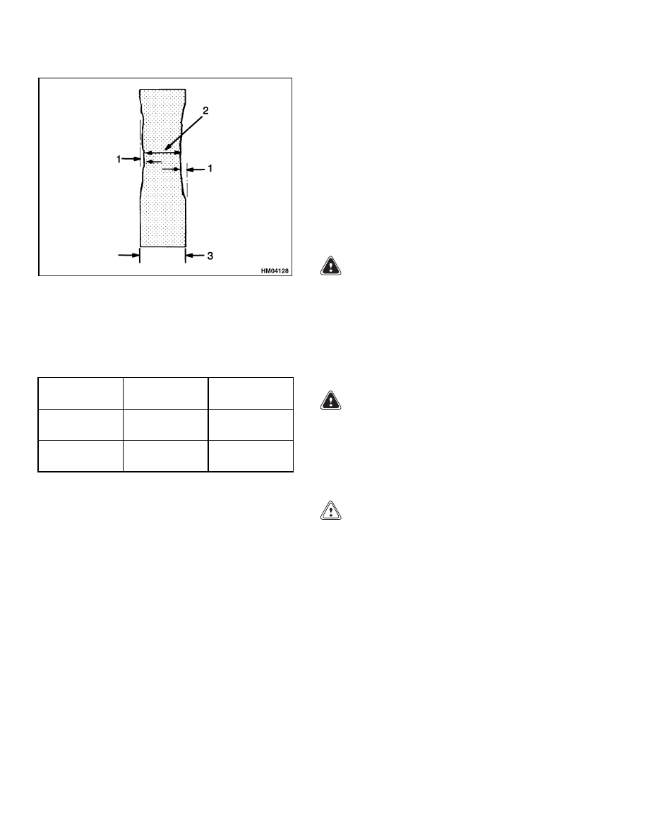
If the disc is worn beyond the wear limits, replace the
disc. See Figure 4 and Table 1.
5
Parking Brake Caliper Repair
1800 SRM 1037
1.
MAXIMUM DISC THICKNESS
2.
MINIMUM DISC THICKNESS
3.
ORIGINAL DISC THICKNESS
Figure 4. Disc Maximum Wear Limits
Table 1. Disc Wear Limits
Original Disc
Thickness
Maximum Disc
Wear
Minimum Disc
Wear
12.7 mm
(0.5 in.)
1.5 mm
(0.06 in.)
9.7 mm
(0.38 in.)
20 mm
(0.79 in.)
1.5 mm
(0.06 in.)
17 mm
(0.67 in.)
Caliper Parts
1.
Inspect the piston, housing bore, and O-ring for
scratches or corrosion. Remove small scratches
or corrosion with fine emery cloth. Replace the
components if there are large scratches or exces-
sive corrosion.
2.
Measure the diameter of the piston at the large
and small end. Replace the piston if the large
end diameter is less than 101.47 mm (3.995 in.)
or the small end diameter is less than 63.37 mm
(2.495 in.).
3.
Measure the diameter of the housing bore at the
large and small end. Replace the housing if the
large end is greater than 101.68 mm (4.003 in.)
or the small end is greater than 63.63 mm
(2.505 in.).
4.
Inspect the housing for damage. If damage can-
not be repaired, replace the housing.
5.
Inspect springs for wear and damage. Always
replace springs as a set.
6.
Inspect the threads of the spring cap for damage.
If damage cannot be repaired, replace the spring
cap.
7.
Inspect the stud and threads on the stud in the
piston. Replace studs if damaged.
8.
Inspect the lining fasteners for wear or damage.
Replace worn or damaged fasteners.
ASSEMBLE
WARNING
Use only specified components when assem-
bling the caliper. Do not use components from
other calipers. If the wrong components are
installed, the caliper will not operate correctly
and can cause damage to the equipment. Use
of parts not approved by Hyster can cause
damage and loss of braking which could result
in serious personal injury.
WARNING
Take care when using Loctite
®
to avoid seri-
ous personal injury.
Follow manufacturer’s
instructions to prevent irritation to eyes and
skin. If Loctite
®
gets into eyes, flush them with
water for 15 minutes. Have eyes checked by a
doctor as soon as possible.
CAUTION
Use a vise with soft jaws in the following step
to prevent damage to the caliper piston.
1.
Apply Loctite
®
277 or equivalent to the threads
of the stud. Using a vise with soft jaws to hold
the piston, install the stud into the piston.
2.
Lubricate the piston outer diameter and ring
groove, housing bore and ring groove, new
O-rings, and backup rings with Dow Corning
®
DC4 or with the type of hydraulic fluid used in
the system.
3.
Install new O-rings and backup rings in both
the piston groove and housing groove so that the
curved side of the backup ring is against each
O-ring. Verify the O-ring on the piston is closest
to the disc. In the housing the O-ring goes closest
to the spring cap. See Figure 5.
6
1800 SRM 1037
Parking Brake Caliper Repair
1.
O-RING
2.
BACKUP RING
3.
SPRING
RETAINING CAP
4.
PISTON
5.
STUD NUT
6.
HOUSING
Figure 5. Parking Brake Caliper
4.
Install the linings.
a. Linings
fastened
with
adhesive
and
setscrews:
(1)
Apply Loctite
®
271, or equivalent, to the
threads of the setscrews.
(2)
Install the setscrews in the piston and
the housing. The top of the screw must
have a clearance of 3 mm (0.12 in.) from
the surfaces of the piston and housing.
(3)
Apply 3M
®
Super 77 spray adhesive,
or equivalent, to the linings where con-
tact is made with the piston and the
housing.
Follow manufacturer’s in-
structions for use of spray adhesive.
(4)
Install the linings on the piston and the
housing.
b. Linings fastened with one-piece snaps:
(1)
Apply Loctite
®
271, or equivalent, to the
threads of the snap fastener screws.
(2)
Screw the snap onto the piston and the
housing. Torque to 5 to 6 N•m (44 to
53 lbf in).
(3)
Align the lining pins with the holes and
engage the snaps on the linings with the
snaps on the piston and the housing.
c.
Linings fastened with screws:
(1)
Apply Loctite
®
271, or equivalent, to the
threads of the screws.
(2)
Attach the linings to the piston and
the housing. Torque the screws to 5 to
6 N•m (44 to 53 lbf in)
5.
Install the piston and lining through the hole for
the spring cap. Press the pistons through the
seals with a steady force.
6.
Apply a graphite base antisieze compound to the
surfaces of the springs and the housing threads
of the spring cap.
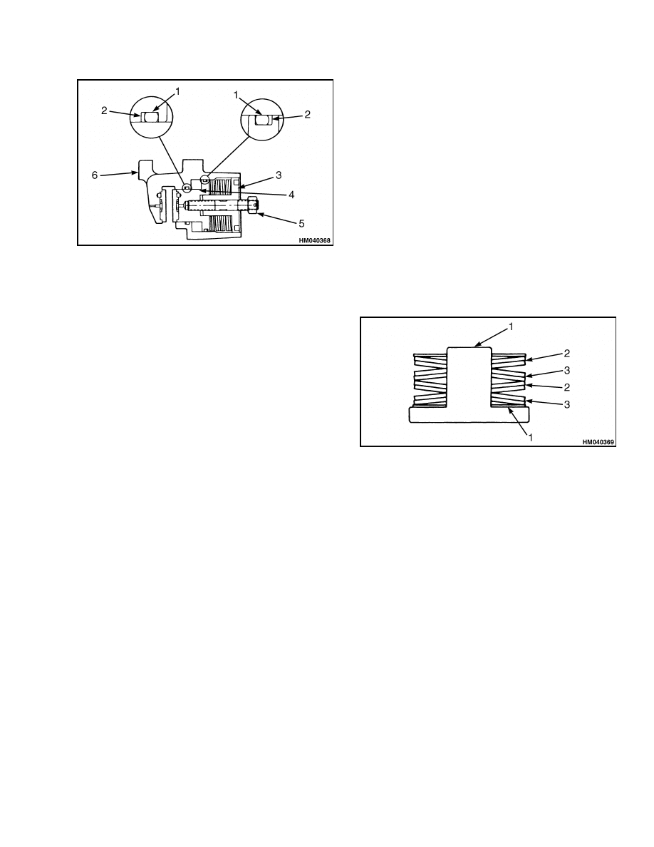
7.
Install the washers and springs on the spring
cap. See Figure 6.
1.
FLAT WASHER
2.
2 SPRINGS, CUP UP
3.
2 SPRINGS, CUP DOWN
Figure 6. Spring Cap
8.
Install the spring cap into the housing. Tighten
the spring cap until the top of the spring cap is
even with the top of the housing.
9.
Install the washer around the stud and attach
the washer with 3M
®
Super 77 spray adhesive, or
equivalent. Follow manufacturer’s instructions
for use of spray adhesive.
10. Install the stud nut at the end of the stud and
fasten in place with the pin.
INSTALL
1.
Check the slide pins and the caliper holes for
nicks, burrs, or other damage that could keep the
caliper from sliding along the pins. Repair or re-
place components as necessary.
7

Parking Brake Caliper Repair
1800 SRM 1037
2.
Apply a graphite base antisieze compound to the
slide pin outside diameter.
3.
Remove the plugs from the brake line and caliper
inlet and connect the line to the inlet.
4.
Remove all air from the brake hydraulic system.
See section Bleed Brakes.
5.
Apply hydraulic pressure to retract the piston to
provide clearance to slide the piston over the disc.
6.
Install the pins and fasteners to hold the caliper
to the mounting bracket.
7.
Verify that the brake slides easily on the slide
pins.
8.
Adjust brakes.
BLEED BRAKES
WARNING
Remove air from the brake system after each
installation or repair of hydraulic or brake sys-
tem components or hydraulic lines. The brakes
will not operate correctly with air in the system
and can cause injury or damage.
WARNING
Properly discard hydraulic fluid that is re-
moved from the brake system. Hydraulic fluid
that is removed can be contaminated and
cause damage, loss of braking, and serious
personal injury.
WARNING
Use only the type of hydraulic fluid specified
by Hyster. Do not use or mix different types
of hydraulic fluid. The wrong hydraulic fluid
can damage rubber parts of the caliper and can
cause damage, loss of braking, and serious per-
sonal injury.
Always start at the point that is the farthest from
the master cylinder and work back toward the mas-
ter cylinder.
Bleed every bleeder screw on every
caliper at every brake position. When you complete
a caliper, go to the next closest caliper at the same
position. When you complete a position, go to the
farthest bleeder screw on the next closest position.
1.
Verify that the master cylinder is filled. Keep the
master cylinder filled during bleeding so you do
not draw air into the system through the master
cylinder. Verify that the master cylinder is filled
when you are done bleeding the system.
2.
Put a clear tube on the bleeder screw. Place the
other end of the clear tube in a container of clean
hydraulic fluid.
3.
Bleed brakes.
a. For full hydraulic systems:
(1)
Slowly apply hydraulic pressure to the
brake.
(2)
Loosen the bleeder screw and continue
to apply pressure until no air bubbles
appear in the container of fluid.
(3)
Tighten the bleeder screw to 20 to
27 N•m (15 to 20 lbf ft). Release the
pressure to the brake.
b. For air/hydraulic or mechanical actuator sys-
tems:
(1)
Apply brake pedal, then loosen the
bleeder screw.
(2)
Tighten the bleeder screw to 20 to
27 N•m (15 to 20 lbf ft) before releasing
the brake, so air is not pulled back into
the system.
(3)
Repeat steps 1 and 2 until no air bub-
bles appear in the container of fluid
when you apply the brake pedal.
4.
Check for fluid leaks.
8
1800 SRM 1037
Parking Brake Caliper Repair
ADJUST
CAUTION
If the brake has too little clearance, it may not
release properly. This will cause the linings to
drag and damage to both linings and the disc.
CAUTION
If there is too much clearance, the clamping
force applied to the disc will be reduced. This
can cause the brake to slip after it is applied.
Too much pressure also puts extra stress on the
springs in the caliper. This can cause prema-
ture spring wear and damage.
Adjust the brake to provide the lining to disc clear-
ance to a maximum of 2.54 mm (0.100 in.) and a min-
imum of 0.5 mm (0.020 in.). Recommended clearance
is 2 mm (0.080 in.).
The brake must have less than 2.54 mm (0.100 in.)
when the brake is released. Check and adjust the
brake until the correct clearance is released.
1.
Apply hydraulic pressure to release the brake.
NOTE: The manual release stud and nut have left-
hand threads.
2.
Remove the cotter pin from the stud nut and
tighten the nut until it touches the spring cap.
This will lock the brake in the release position.
3.
Release hydraulic pressure.
WARNING
Never try to turn or remove the spring cap
when hydraulic pressure is applied to the
brake. Turning the cap while pressure is ap-
plied can cause damage to the O-ring seals and
the spring cap threads. Removing the cap can
cause serious personal injury by the sudden
release of hydraulic pressure.
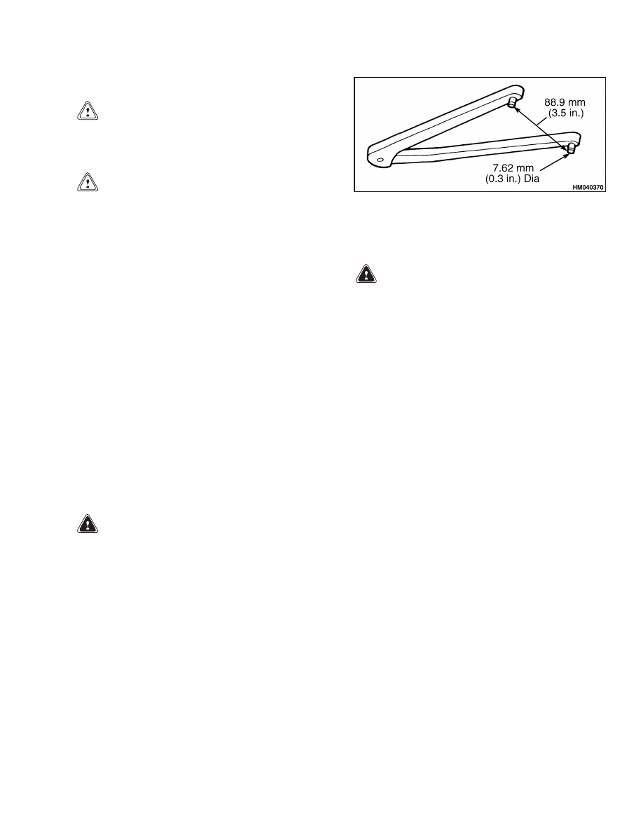
4.
Use a spanner wrench to turn the spring cap to
the disc clearance required. A quarter of a turn
of the spring cap in either direction will change
the total clearance by 0.4 mm (0.016 in.). See
Figure 7.
Figure 7. Spanner Wrench
5.
Apply hydraulic pressure to the brake to over-
come the spring pressure.
WARNING
Verify that the nut is at the end of the stud be-
fore you put the vehicle in service. If the nut
is tightened against the spring cap, the brake
cannot be applied and serious personal injury
can result.
6.
Loosen the stud nut and move it to the end of
the stud. Install the cotter pin to hold the nut in
place.
7.
Verify that the brake slides easily on the slide
pins.
8.
Install the centering device if one was removed
from the end of the caliper.
TEST
NOTE: The caliper should always be tested after it is
assembled and before it is put into service.
1.
Apply hydraulic pressure to verify that the
caliper will release when required. If the piston
does not retract in the housing, readjust the
brake.
2.
Release the hydraulic pressure and verify that
the springs expand and force the piston out to
apply the brake. If not, remove and disassemble
the caliper and find and correct the problem.
3.
To verify that there are no leaks, apply and re-
lease the hydraulic pressure three times. If there
is a leak, disassemble and repair or replace com-
ponents as necessary.
9

Troubleshooting
1800 SRM 1037
Specifications
Table 2. Torque Requirements
Component
Torque
Lining snap fastener screws
5 to 6 N•m (44 to 53 lbf in)
Bleeder screws
20 to 27 N•m (15 to 20 lbf ft)
Table 3. Wear Limits
Component
Replace
Disc
Wear exceeds maximum of 1.524 mm (0.06 in.)
Housing
Large end bore diameter exceeds 101.68 mm (4.003 in.) or small end bore exceeds
63.63 mm (2.505 in.).
Linings
Thickness is less than 3 mm (0.125 in.) from piston or housing.
Piston
Large end diameter is worn to less than 101.47 mm (3.995 in.) or small end is worn to
less than 63.37 mm (2.495 in.).
Table 4. Lining to Disc Clearance
Maximum
2.54 mm (0.100 in.)
Minimum
0.5 mm (0.020 in.)
Troubleshooting
PROBLEM
POSSIBLE CAUSE
PROCEDURE OR ACTION
The parking brake does not
release.
The hydraulic pressure is too low.
Check for low fluid level, air in sys-
tem, restricted lines, fluid leaks,
damaged seals or seals installed
backward.
The piston is cocked in the bore.
Replace piston if large end diameter
is less than 101.47 mm (3.995 in.) or
the small end is less than 63.37 mm
(2.495 in.).
Replace housing if the
large end of bore exceeds 101.68 mm
(4.003 in.) or the small end of the
bore exceeds 63.63 mm (2.505 in.).
10

1800 SRM 1037
Troubleshooting
PROBLEM
POSSIBLE CAUSE
PROCEDURE OR ACTION
The parking brake will not
apply.
The springs in the brake caliper are
damaged.
Replace springs.
The piston is cocked in the bore.
Replace piston if large end diameter
is less than 101.47 mm (3.995 in.) or
the small end is less than 63.37 mm
(2.495 in.).
Replace housing if the
large end of bore exceeds 101.68 mm
(4.003 in.) or the small end of the
bore exceeds 63.63 mm (2.505 in.).
The caliper is locked in the released
position.
Move the stud nut to the end of the
stud.
The brake does not hold.
Brake is not properly adjusted.
Adjust the brake.
Linings or disc is excessively worn.
Replace linings when the thick-
ness of the lining is less than 3 mm
(0.118 in.) from the piston or hous-
ing.
Replace the disc when wear
exceeds a maximum of 1.524 mm
(0.06 in.).
Linings are contaminated with oil or
grease.
Replace linings.
The springs in the brake caliper are
damaged.
Replace springs.
Damaged seals.
Wrong type of fluid is being used.
Drain, flush, and refill with the
correct fluid.
Replace O-rings and
backup rings.
Spring cap turned when hydraulic
pressure was applied to the brake.
Replace O-rings and backup rings.
Damaged springs.
Brake is not properly adjusted.
Springs worn.
Replace the springs and adjust the
brake.
Lack of lubrication.
Replace the springs and apply an an-
tiseize compound to the springs.
11

Troubleshooting
1800 SRM 1037
PROBLEM
POSSIBLE CAUSE
PROCEDURE OR ACTION
Damaged linings or disc.
Brake is not properly adjusted. Lin-
ings are dragging.
Adjust brake.
Replace parts as
needed.
The caliper is seized on the slide
pins.
Clean, replace or repair slide pins or
caliper. Replace linings.
The piston is cocked in the bore.
Replace piston if large end diameter
is less than 101.47 mm (3.995 in.) or
the small end is less than 63.37 mm
(2.495 in.).
Replace housing if the
large end of bore exceeds 101.68 mm
(4.003 in.) or the small end of the
bore exceeds 63.63 mm (2.505 in.).
12


TECHNICAL PUBLICATIONS
1800 SRM 1037
3/05 (2/03) Printed in United Kingdom
Document Outline
- toc
- tables
Wyszukiwarka
Podobne podstrony:
więcej podobnych podstron