
AIR
CONDITIONING
SYSTEM
Return To Main Table of Contents
GENERAL . . . . . . . . . . . . . . . . . . . . . . . . . . . . . . . . . . . . . . . . . . . . . .
HEATER CONTROL ASSEMBLY . . . . . . . . . . . . . . . . . . . . . . . 12
HEATER . . . . . . . . . . . . . . . . . . . . . . . . . . . . . . . . . . . . . . . . . . . . . . .
VENTILATORS . . . . . . . . . . . . . . . . . . . . . . . . . . . . . . . . . . . . . . . . . 1 7
AIR CONDITIONER SYSTEM . . . . . . . . . . . . . . . . . . . . . . . . .
COMPRESSOR ASSEMBLY . . . . . . . . . . . . . . . . . . . . . . . . . . .
EVAPORATOR ASSEMBLY . . . . . . . . . . . . . . . . . . . . . . . . . . . .
CONDENSER ASSEMBLY . . . . . . . . . . . . . . . . . . . . . . . . . . . . .
CONDENSER FAN & RELAY . . . . . . . . . . . . . . . . . . . . . . . . .
BLOWER ASSEMBLY . . . . . . . . . . . . . . . . . . . . . . . . . . . . . . . . . .
ACCUMULATOR ASSEMBLY . . . . . . . . . . . . . . . . . . . . . . . . . .
GENERAL
SPECIFICATION (H.C.C)
Heater assembly
Type
Heating capacity
Air conditioner
Cooling capacity
Compressor
Model
No. of cylinders and displacement CC/Rev
Maximum allowable continuous rpm
Magnetic clutch
Voltage, power consumption
Control
Idle up device (FBC only)
Protective equipment
Clutch cycling switch
Cut out pressure
Max. cut in pressure
Min. difference pressure
Pressure relief valve
Relief pressure
Exhaust flow
Resealed pressure
Refrigerant and quantity gr. (oz, lb.)
3,800 Kcal/h (15,000 B.T.U/h)
3,300 Kcal/h (13,000 B.T.U/h)
SD-709
7 cylinders, 155
6000
DC12V, 49W
900 ± 25 rpm
167 kPa (1.7 ± 0.1 kg/cm
2
, 24 psi)
324 kPa (3.3 kg/cm
2
, 47 psi)
118 kPa (1.2 kg/cm
2
, 17 psi)
31.6 kg/cm
2
(449 psi) MIN., 42.18 kg/cm
2
(560 psi) MAX.
Min. 113.2
at 42.18 kg/cm
2
(560 psi)
Min. 28.2 kg/cm
2
(401 psi)
R - 1 2 8 5 0 - 9 0 0 ( 3 0 - 3 2 , 1 . 8 7 - 1 . 9 2 )
SERVICE STANDARDS
Amount of deflection of V belt mm (in.)
Engine idle speed
Air gap mm (in.)
8 . 0 - 1 0 . 0 ( 0 . 3 2 - 0 . 4 0 )
700±50 rpm (without MPI)
0.4-0.8 (0.016-0.032)
LUBRICANTS
Recommended lubricant
Quantity
Heater control lever
Compressor oil
Multipurpose grease
Suniso 5GS or equivalant
As required
240 cc (8.1 fl oz)
9 7 - 2
GENERAL
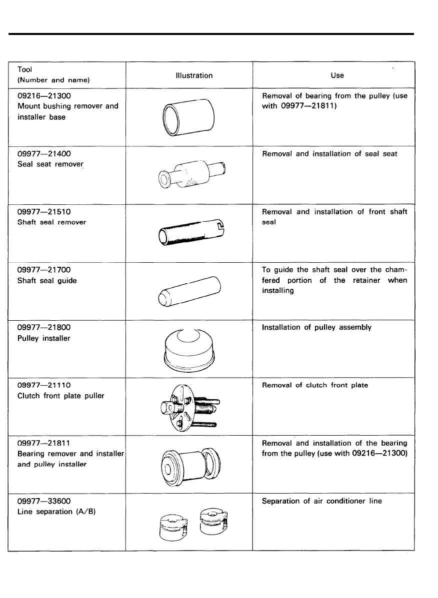
SPECIAL TOOLS
9 7 - 3

GENERAL
TROUBLESHOOTING
INSUFFICIENT OR NO A/C COOLING-FIXED ORIFICE TUBE CYCLING CLUTCH SYSTEM
TEST STEP
RESULT
ACTION TO TAKE
A1
VERIFY THE CONDITION
Check system operation
System cooling
INSTRUCT vehicle owner
properly
on proper use of the
system
System not cooling
GO to A2
Properly
A2 CHECK A/C COMPRESSOR CLUTCH
Does the A/C compressor clutch engage?
Yes
No
GO to A3
REFER to clutch circuit
diagnosis in this section
A3 CHECK OPERATION OF COOLING FAN
Check that the cooling fan runs when the A/C Yes
compressor clutch is engaged
No
GO to A4
Check for cooling fan
electric circuit
A4 COMPONENT CHECK
o Under-hood check of the following:
OK but still not
GO to A6
Loose, missing or damaged compressor drive belt.
cooling
Loose or disconnected A/C clutch or clutch cycling
Not OK
REPAIR AND GO to A5
pressure switch connectors.
Disconnected resistor assembly.
Loose vacuum lines or misadjusted control cables
o Inside vehicle check for:
Blown fuse or improper blower motor operation.
Vacuum motors/temperature door movement-full
travel.
Electrical and vacuum connections.
A5 CHECK SYSTEM
Check system operation
OK
Condition Corrected
GO to A1
Not OK
GO to A6
9 7 - 4

GENERAL
INSUFFICIENT OR NO A/C COOLING-FIXED ORIFICE TUBE CYCLING CLUTCH SYSTEM
(Continued)
TEST STEP
RESULT
ACTION TO INTAKE
A6 CHECK COMPRESSOR CLUTCH
Use refrigerant system clutch cycle rate and timing
Compressor cycles
GO to A7
evaluation charts.
very rapidly
Prepare the car as follows
(1 second on)
1. Hook up the manifold gauge set
(1 second off)
2. Set Function lever at max A/C
3. Set blower switch on high
Compressor runs
GO to A8
4. Set temperature lever full cold
continuously (normal
5. Close doors and windows
operation in ambient
6. Use a thermometer to check temperature at center
temperature above
discharge register. Record outside temperature.
27°C. (80°F.)
7. Run engine at approximately 1500 RPM with
depending on
compressor clutch engaged.
humidity conditions)
8. Stabilize with above conditions for 10-15 minutes.
Compressor cycles
GO to A7
Check compressor clutch ON/OFF time. Refer to slow
charts for normal Clutch cycling timing rates.
A7
CHECK CLUTCH CYCLING PRESSURE SWITCH
Bypass the clutch cycling pressure switch with a jumper
Outlet line same
REPLACE clutch cycling
wire.
temperature
pressure switch. Do not
Compressor on continuously.
approximately -2°C. discharge system
Feel evaporator inlet and outlet lines.
4°C. (28°F. - 40°F.)
Switch fitting has
or slightly colder
Schrader valve GO to A8
than inlet line (after
fixed orifice)
Inlet line warmer or GO to A9
(after fixed orifice)
colder than outlet
line
9 7 - 5

GENERAL
INSUFFICIENT OR NO A/C COOLING-FIXED ORIFICE TUBE CYCLING CLUTCH SYSTEM
(Continued)
TEST STEP
RESULT
ACTION TO TAKE
A8 CHECK SYSTEM PRESSURES
Compare readings with normal system pressure ranges. Clutch cycles within
System OK
limits. System pres- GO to A1
sure within limits
Compressor runs
GO to A11
continuously (normal
operation in ambient
temperature above
27°C (80°F.)
depending on
humidity conditions).
Compressor cycles
REPLACE clutch cycling
high or low ON
pressure switch. Do not
above 359 kPa
discharge system
(52 psi) OFF below
Switch timing has
144 kPa (21 psi).
Schrader valve CHECK
system OK.GO to A1
NOT OK.GO to A9
A9 CHECK SYSTEM
Check system for leaks
Leak found
REPAIR, discharge, evac-
uate and charge system.
System OK
GO to A1
No Leak found
Low refrigerant charge
or moisture in system.
Discharge, evacuate and
charge system. System
O K
A10 CHECK CLUTCH CYCLING
Disconnect blower motor wire and check for clutch Clutch cycles OFF
cycling off at 144 kPa (21 psi) (suction pressure)
at 144-179 kPa
(21-26 psi)
Connect blower motor
wire.
System OK
GO to A1
Pressure falls below REPLACE clutch cycling
144 kPa (21 psi)
pressure switch. Do not
discharge system.
Switch fitting has
Schrader valve. System
OK.GO to A1
9 7 - 6

GENERAL
COMPRESSOR CIRCUIT CLUTCH DIAGNOSIS
TEST STEP
RESULT
ACTION TO TAKE
B1
CHECK SYSTEM OPERATION
o Turn the blower switch ON.
Clutch and fan operate System OK
o Depress the A/C button.
o Turn the ignition switch to the RUN position.
Clutch and fan do not GO to B2
o Compressor clutch should engage and engine
operate
cooling fan should operate.
Only fan operates
GO to B5
B2 CHECK FOR VOLTAGE
o Check for voltage at circuit wire at the clutch Voltage present
cycling pressure switch connector.
No voltage
B3 BY-PASS PRESSURE SWITCH
o Disconnect the connector at the clutch cycling
OK
pressure switch
o Jump connector pins.
Not OK
o Clutch should engage.
GO to B3
GO to A1
GO to B4
GO to B5
B4 CHECK SYSTEM PRESSURE
o Connect the manifold gauge set and check the Pressure above 55 psi REPLACE clutch cycling
system pressure.
pressure switch GO to A1
Pressure below 55 psi CHECK refrigerant
(ambient temperature
system for leaks.
above 50°F)
REPAIR and CHARGE
system as necessary
GO to A1.
B5
CHECK VOLTAGE AT CLUTCH
o Check for voltage at the clutch field coil.
B6
CHECK VOLTAGE AT BATTERY
o Check for voltage at the battery.
B7 CHECK FUSE
Voltage present
No voltage
Voltage Present
No voltage
GO to B7
GO to B6
GO to B7
Check for low battery voltage.
SERVICE as necessary.
GO to A1.
o Check fuse in panel for continuity.
OK
Not OK
GO to B1.
CHECK for short.
SERVICE as necessary.
REPLACE fuse. GO to B1.
9 7 - 7
GENERAL
SERVICE ADJUSTMENT
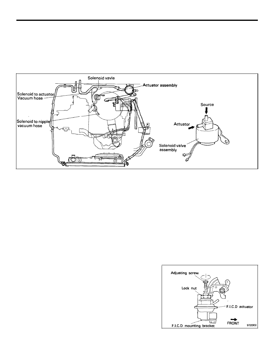
ADJUSTMENT OF FAST IDLE CONTROL DEVICE
(without MPI) (F.I.C.D)
The vacuum system is designed to actuate the F.I.C.D. which
raises the idle speed of the engine to ensure better cooling when
the car is stationary.
1. Warm up the engine.
2.
Make sure the engine is at the correct idle speed with the
air conditioner in the “OFF” position.
3. Set the engine speed to the specified rpm with the air
conditioner in the “ON” position.
Specified rpm : 900 ± 25 rpm
4.
Depress and release the accelerator pedal several times, and
make sure that the engine speed returns to the specified
rpm.
9 7 - 8
GENERAL
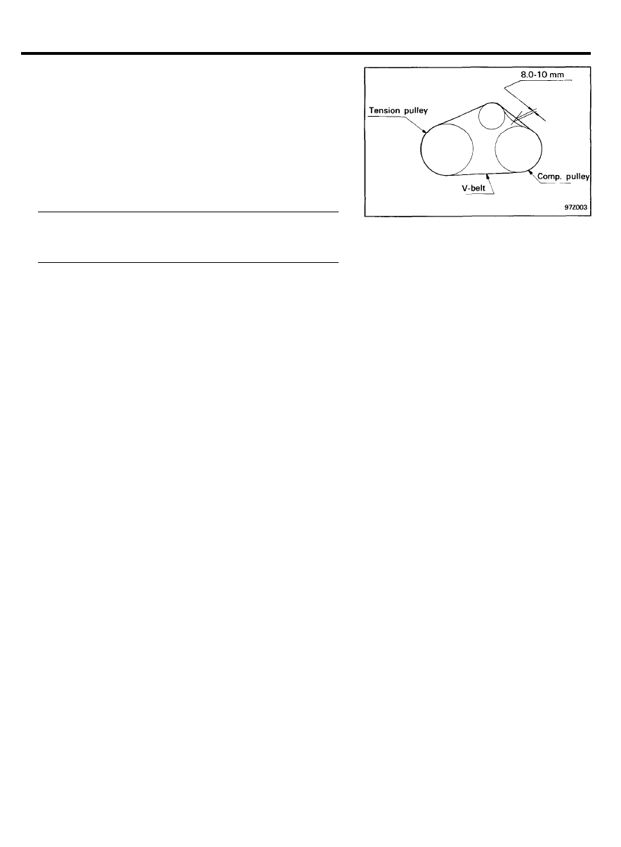
CHECKING AND ADJUSTING THE A/C
COMPRESSOR BELT
After installation, check the following points:
1. Check for abnormal vehicle performance.
2.
Check the magnetic clutch for operation (without turning on
the compressor).
3.
Check for any parts left unmounted or any tool left behind
in the vehicle.
4. Check the belt for proper tension.
Belt deflection
Air conditioner compressor belt . . . . . . . . . . . . . . . . . . . . . . .
8.0-10.0 mm (0.34-0.42 in.)
5. Charge the system.
6. Check the idle speed.
7. Test the system for proper operation.
9 7 - 9
GENERAL
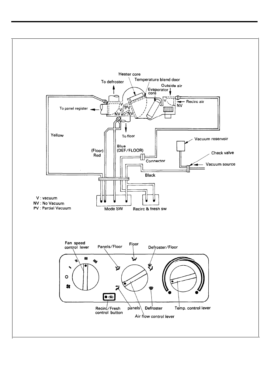
VACUUM SYSTEM SYMPTOM AND PROBABLE CAUSE
9 7 - 1 0

GENERAL
Symptom
On “FLOOR” position. All air through
defroster or DEF/FLOOR.
Probable cause
o Blue and/or red vacuum hose pinched or disconnected at
vacuum motor.
o Black source hose pinched or disconnected at the connector.
o Engine compartment A/C source hose pinched or discon-
nected at the vacuum manifold.
o Defective vacuum motor.
On “DEF/FLOOR” position. All air through
defroster.
o Blue hose pinched or disconnected at vacuum motor.
o Blue vacuum hoses installed improperly (reversed).
o Black source hose pinched or disconnected at the connector.
o Engine compartment A/C source hose pinched or discon-
nected at the vacuum manifold.
o Defective vacuum motor.
On “PANEL VENTS” position. All air
through defroster.
o Yellow vacuum hose pinched or disconnected at vacuum
motor.
o Black source hose pinched or disconnected at the connector.
o Engine compartment A/C source hose pinched or discon-
nected at the vacuum manifold.
o Defective vacuum motor.
On “PANEL/FLOOR” position. All air
through defroster or panel
o Yellow vacuum hose pinched or disconnected at vacuum
motor.
o Blue hose pinched or disconnected at vacuum motor.
o Black source hose pinched or disconnected at the connector.
o Engine compartment A/C source hose pinched or discon-
nected at the vacuum manifold.
o Defective vacuum motor.
On “DEF” position. (No vacuum)
On “RECIRC” position. All air through
fresh.
o White vacuum hose disconnected at the connector or recirc
duct vacuum motor.
o Black source hose pinched or disconnected at the connector.
o Engine compartment A/C source hose pinched or discon-
nected at the vacuum manifold.
o Defective vacuum motor.
9 7 - 1 1
HEATER CONTROL ASSEMBLY
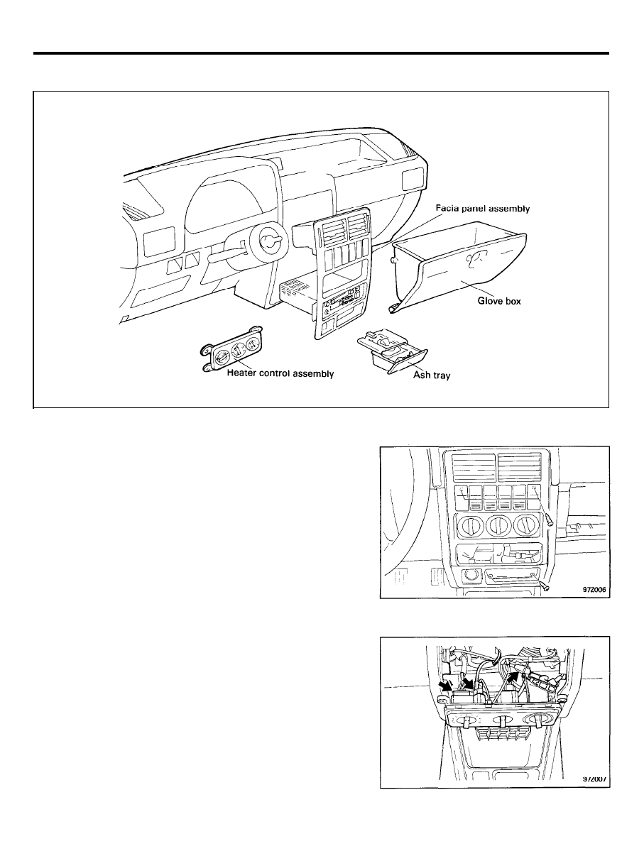
HEATER CONTROL ASSEMBLY
COMPONENTS
REMOVAL AND INSTALLATION
1. Pull out the ash tray and remove the bolt.
2. Pull out the heater control panel assembly and then
disconnect the A/C switch, defrostor and cigar lighter
connectors.
3. Remove the heater control assembly mounting bolts.
4.
Pull out the heater control assembly and then disconnect the
blower motor switch connector, vacuum connector and the
temperature control cable.
5. Installation is the reverse of removal.
9 7 - 1 2
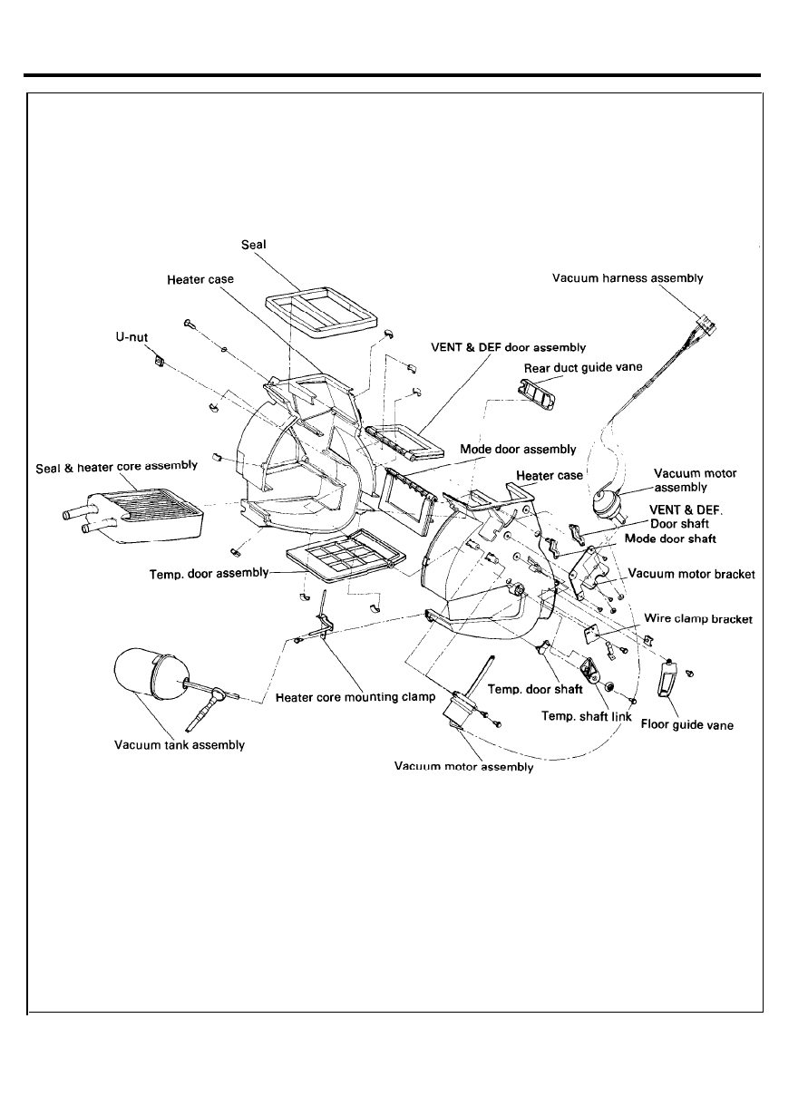
HEATER
COMPONENTS VACUUM TYPE
9 7 - 1 3
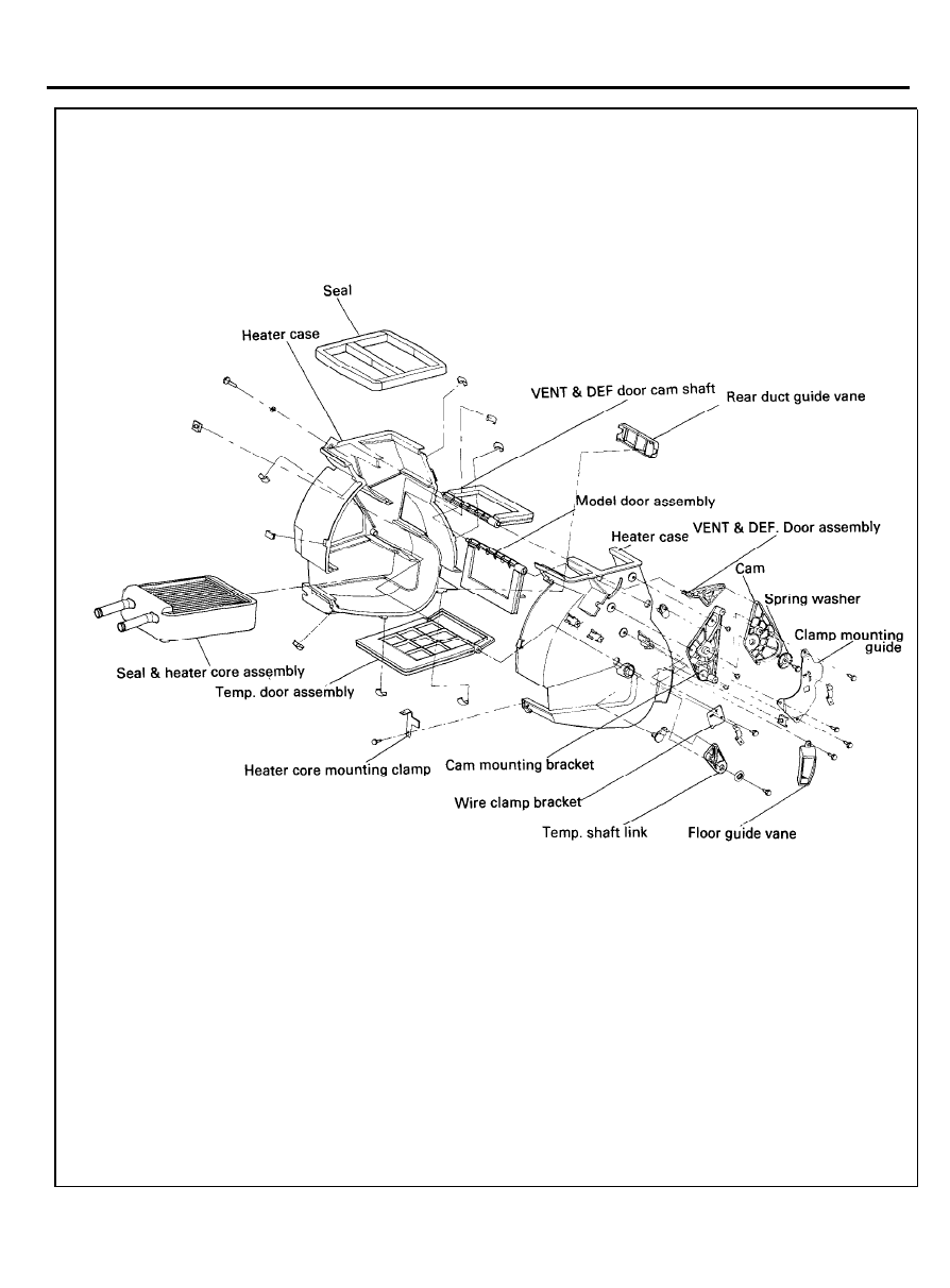
HEATER
COMPONENTS LEVER TYPE
9 7 - 1 4
VENTILATORS
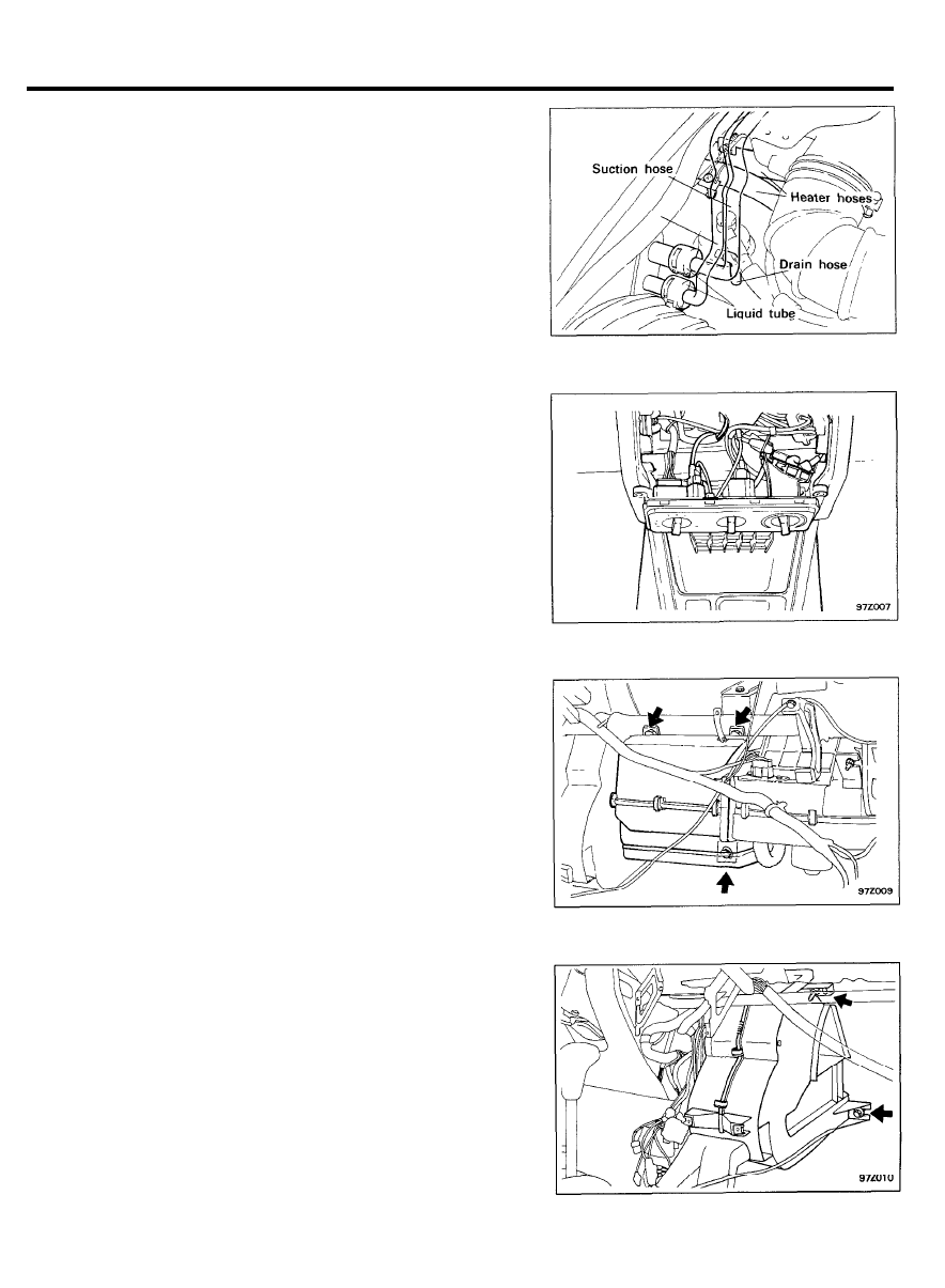
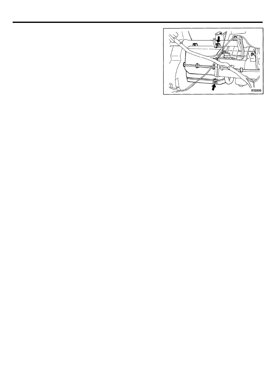
REMOVAL
1. Disconnect the negative terminal at the battery.
2. Drain the coolant from the radiator.
3. Remove the heater hoses and the evaporator drain hose.
4. Using the special tool (09977-33600 A/B), remove the
suction and the liquid lines.
5. Remove the console assembly (Refer to BODY GROUP).
6. Remove the glove box assembly, main lower crash pad
assembly and lower crash pad center facia panel assembly
(Refer to BODY GROUP).
7. Remove the heater control assembly.
8.
Remove the lower crash pad center skin assembly (Refer to
BODY GROUP).
9. Remove the crash pad center support bracket assembly
(Refer to BODY GROUP).
10. Remove the evaporator unit assembly.
11. Remove the rear heating joint duct assembly.
12. Remove the heater unit assembly.
9 7 - 1 5

HEATER
INSPECTION
1. Check the linkage mechanism for operation.
2. Check the heater core for restrictions or leakage.
INSTALLATION
1. Installation is the reverse of the removal procedures.
9 7 - 1 6
VENTILATORS
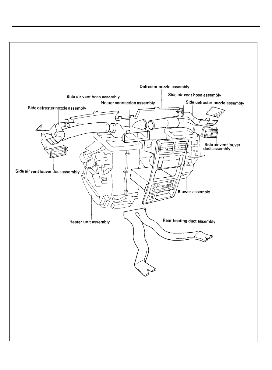
V E N T I L A T O R S
COMPONENTS
9 7 - 1 7
HEATER
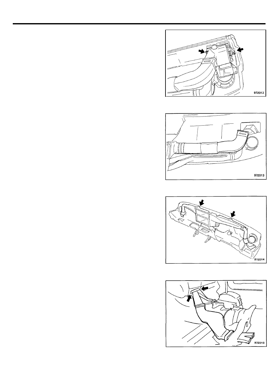
REMOVAL AND INSTALLATION
1. Remove the main crash pad assembly (Refer to BODY
GROUP)
2. Remove the side air vent louver duct assembly (LH/RH).
3. Remove the side air vent hose assembly (LH/RH).
4. Remove the side air vent louver assembly (LH/RH).
5. Remove the heater connection assembly.
6. Remove the defroster nozzle assembly.
7. Remove the side defroster nozzle assembly (LH/RH).
8. Remove the crash pad upper cover assembly.
9. Remove the rear heating joint duct assembly and rear
heating side duct assembly (LH/RH).
10. Installation is the reverse of removal procedures.
9 7 - 1 8
AIR CONDITIONER SYSTEM
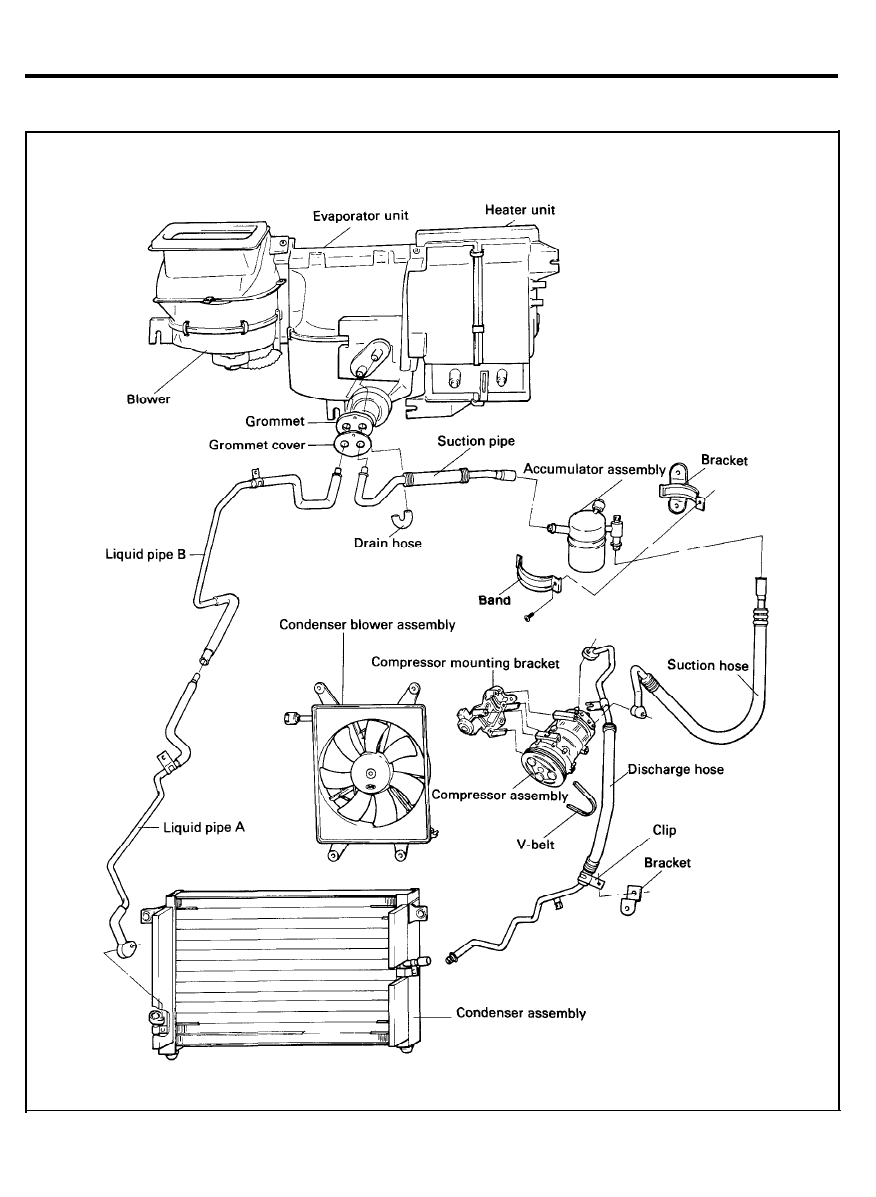
AIR CONDITIONER
COMPONENTS
TORQUE : Nm (kg.cm, Ib.ft)
9 7 - 1 9
AIR CONDITIONER SYSTEM
AIR CONDITIONER SYSTEM SERVICE
CAUTIONS
0
0
0
0
0
0
0
0
0
0
0
0
0
Never open or loosen a connection before discharging the
system.
When loosening a connection, if any residual pressure is
evident, allow it to bleed off before opening the fitting.
A system which has been opened to replace a component
or one which has discharged must be evacuated before
charging.
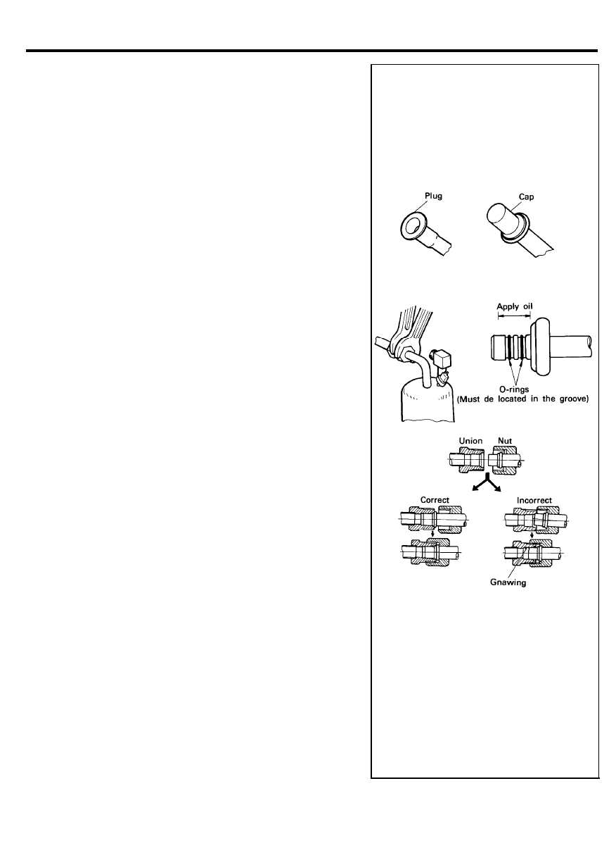
Immediately after disconnecting a component from the
system, seal the open fittings with a cap or plug.
Before disconnecting a component from the system, clean
the outside of the fittings thoroughly.
Do not remove the sealing caps from a replacement
component until it is ready to be installed.
Refrigerant oil will absorb moisture from the atmosphere if
left uncapped. Do not open an oil container until ready to
use, and install the cap immediately after using. Store oil
only in a clean, moisture-free container.
Before connecting an open fitting, always install a new
sealing ring. Coat the fitting and seal with refrigerant oil
before making the connection.
When installing a refrigerant line, avoid sharp bends.
Position the line away from the exhaust or any sharp edges
which may chafe the line.
Tighten fittings only to the specified torque. The fittings used
in the refrigerant system should not be over-tightened.
When disconnecting a fitting, use a wrench on both sides
of the fitting to prevent twisting the refrigerant lines.
Do not open a refrigerant system or uncap a replacement
component unless it is as close as possible to room
temperature. This will prevent condensation from forming
inside a component which is cooler than the surrounding air.
Whenever a major component such as an evaporator,
condenser, compressor, or refrigerant line is replaced, it is
mandatory that the accumulator/drier also be replaced.
Keep service tools and the work area clean. Contamination
of a refrigerant system through careless work habits must
be avoided.
9 7 - 2 0
AIR CONDITIONER SYSTEM
AIR CONDITIONER SYSTEM SERVICE
SAFETY PRECAUTIONS
1.
R-12 liquid refrigerant is highly volatile. A drop on the skin
of your hand could result in localized frostbite. When
handling the refrigerant, be sure to wear gloves.
2. If the refrigerant splashes into your eyes, wash them with
clean water immediately. It is standard practice to wear
goggles or glasses to protect your eyes, and gloves to protect
your hands.
3. The R-12 container is highly pressurized. never leave it in
a hot place, and check that the storage temperature is below
52°C (126°F).
4.
A halide leak detector is often used to check the system for
refrigerant leakage. Bear in mind that R-12, upon coming
into contact with flame (this detector burns propane to
produce a small flame), produces phosgene, a toxic gas.
INSTALLATION OF MANIFOLD GAUGE SET
1. Close both hand valves of the manifold gauge.
2. Install the charging hoses of the gauge set to the fittings.
Connect the low-pressure hose to the low-pressure service
port, and the high-pressure hose to the high-pressure service
port.
Tighten the fittings by hand.
NOTE
Fittings for attaching the manifold gauge set are located
on the compressor discharge hose and the accumulator.
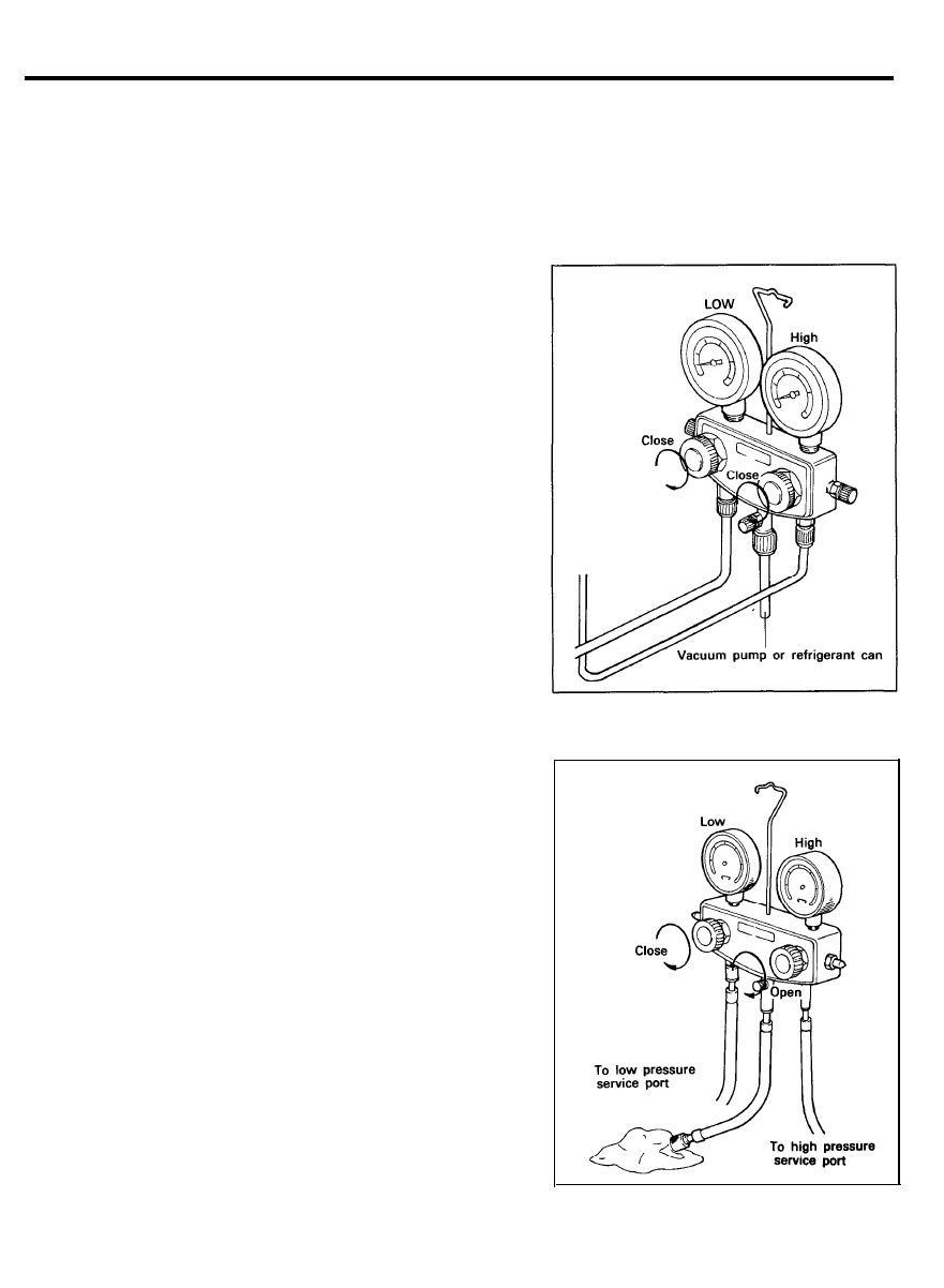
DISCHARGING THE REFRIGERATION
SYSTEM
1. Connect the manifold gauge set to the system.
2. Place the free end of the center hose on a shop towel.
3. Slowly open the high-pressure hand valve to adjust the
refrigerant flow. Open the valve slightly.
NOTE:
If refrigerant is allowed to escape too fast, compressor oil
will be drawn out of the system.
4. Check the shop towel to make sure no oil is being
discharged. If oil is present, partially close the hand valve.
5.
After the manifold gauge reading drops below 434 kPa (3.5
kg/cm
2
, 50 psi), slowly open the low-pressure hand valve.
6.
As the system pressure drops, gradually open both the high
and the low-pressure hand valves until both gauges read 1
kPa (0 kg/cm
2
, 0 psi).
9 7 - 2 1
AIR CONDITIONER SYSTEM
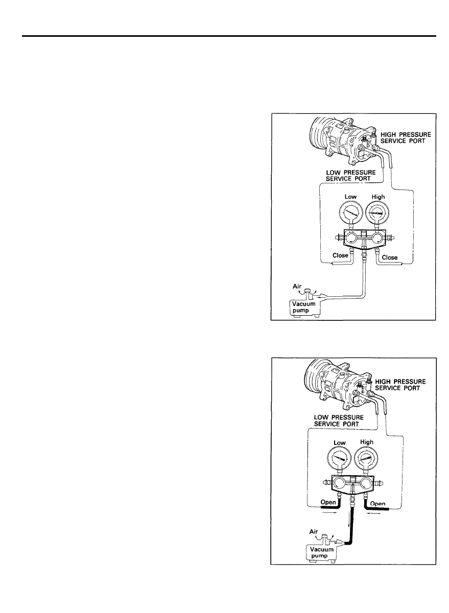
EVACUATING REFRIGERANT SYSTEM
NOTE:
It is necessary to evacuate the air conditioning system any
time the system has been opened. Evacuation is necessary to
purge the system of all air and moisture that may have been
allowed to enter the unit.
After installation of a component, the system should be
evacuated for approximately 15 minutes. A component in
service that has been opened for repair should be evacuated
for 30 minutes.
1. Engine should be off.
2.
Connect a manifold gauge set to the service ports. Close both
high and low pressure valves.
3. Make sure the refrigerant has been discharged from the
system.
4. Connect the center hose of the gauge set to the vacuum
pump inlet.
5. Start the vacuum pump and then open the high and low
manifold pressure valves.
6.
After about ten minutes, check that the low pressure gauge
reads more than 94.39 kPa (0.96 kg/cm
2
, 13.7 psi) vacuum.
If negative pressure can not be obtained, there is a leak in
the system. In this case, repair the leak as described in the
following.
1) Close both the manifold valves and stop the vacuum
pump.
2) Charge the system with a can of refrigerant [about 0.4
kg (0.9 lb)]. Refer to Charging Refrigerant.
3) Check for refrigerant leakage with a leak detector.
4)
Repair any leakage found. Refer to Checking Refrigerant
Leaks.
5) Discharge the system again, and then evacuate the
system.
7. Start the vacuum pump.
8. Open both manifold pressure valves to obtain 94.39 kPa
(0.96 kg/cm
2
, 13.7 psi) of vacuum.
9.
After the low pressure manifold gauge indicates as close to
94.39 kPa (0.96 kg/cm
2
, 13.7 psi) as possible, continue
evacuating for 15 minutes.
10. After evacuating for 15 minutes, close both manifold
pressure valves and stop the vacuum pump. Disconnect the
hose from the vacuum pump. The system is now ready for
charging.
9 7 - 2 2
AIR CONDITIONER SYSTEM
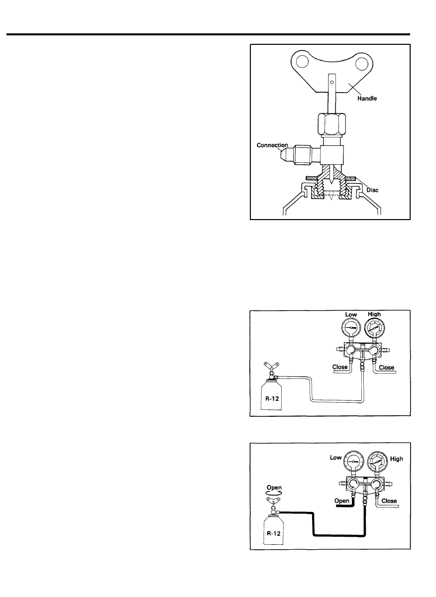
HANDLING REFRIGERANT SERVICE TAP
VALVE
1.
Before connecting the valve to the refrigerant container, turn
the handle fully counterclockwise.
2.
Turn the adapter counterclockwise until it reaches its highest
position.
3.
Connect the center hose to the valve fitting. Turn the adapter
fully clockwise by hand.
4.
Turn the handle clockwise to make a hole in the sealed top.
5.
Turn the handle fully counterclockwise to fill the center hose
with air. Do not open the high and low-pressure hand valves.
6.
Loosen the center hose nut connected to the center fitting
of the manifold gauge.
7.
Allow air to escape for a few seconds, and then tighten the
nut.
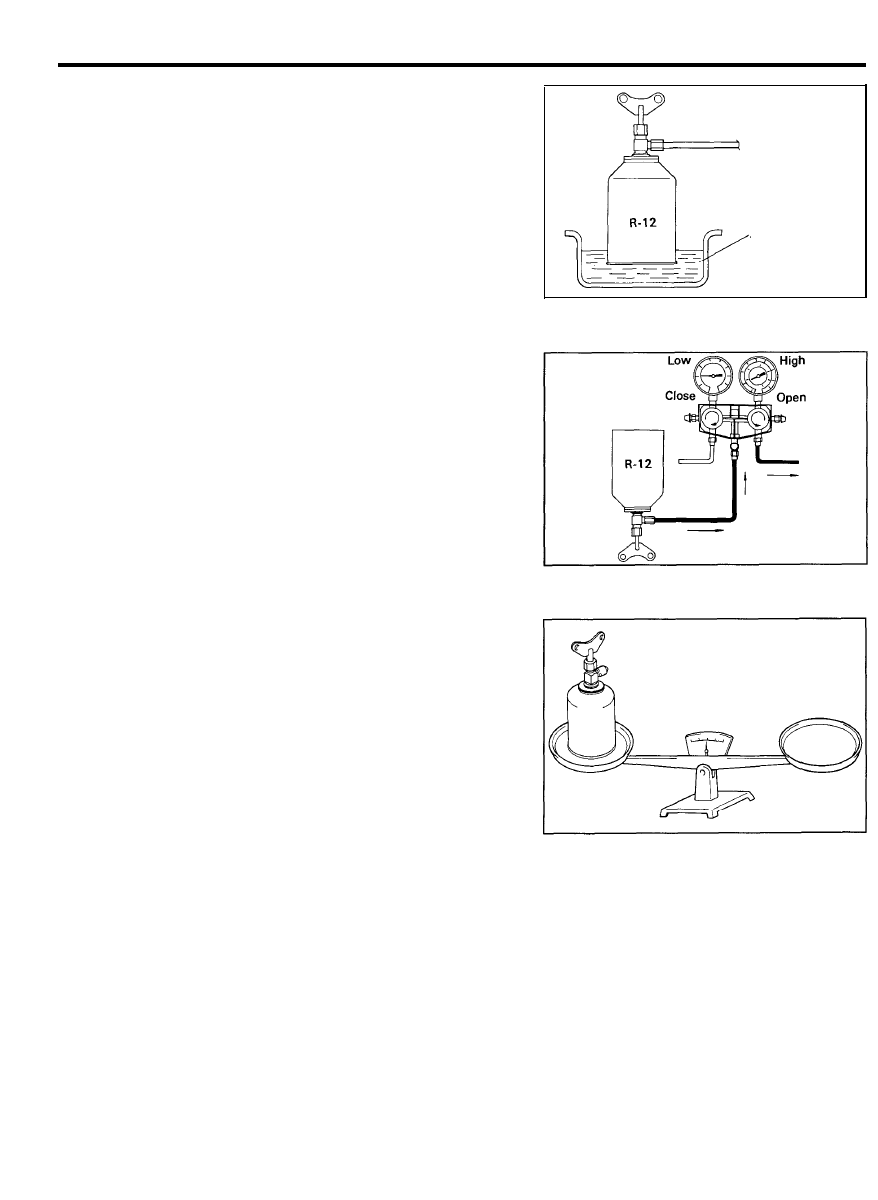
CHARGING REFRIGERANT SYSTEM
(VAPOR)
NOTE
This step is to charge the system through the low pressure
side with refrigerant in a vapor state. When the refrigerant
container is placed rightside up, refrigerant will enter the
system as a vapor.
1 .
2 .
3.
4.
5.
Install the refrigerant can tap valve as described in Handling
the Refrigerant Service Tap Valve section.
Open the low pressure valve. Adjust the valve so that the
low pressure gauge does not read over 412 kPa (4.2 kg/cm
2
,
60 psi).
Put the refrigerant in a pan of warm water (maximum
temperature 40°C or (104°F) to keep vapor pressure in the
container slightly higher than vapor pressure in the system.
Run the engine at fast idle, and operate the air conditioner.
NOTE:
Be sure to keep the container upright to prevent liquid
refrigerant from being charged into the system through
the suction side, resulting in possible damage to the
compressor.
Charge the system to the specified amount. Then, close the
low pressure valve.
Specified amount: 850-900 g (1.87-1.92 lb)
9 7 - 2 3
AIR CONDITIONER SYSTEM
When refrigerant charging speed is slow, immerse the
refrigerant can in water, heated to a temperature of about
40°C (104°F).
WARNING
o Under no circumstances should the refrigerant can be
warmed in water heated to a temperature of over 52°C
(126°F).
o A blow torch or stove must never be used to warm up the
can.
CHARGING REFRIGERANT SYSTEM
(LIQUID)
NOTE
This step is to charge an empty system through the high
pressure side with refrigerant in a liquid state. When the
refrigerant container is held upside down, refrigerant will enter
the system as a liquid.
CAUTION:
Never run the engine when charging the system through the
high pressure side.
Do not open the low pressure valve when the system is being
charged with liquid refrigerant.
1.
Close both the high and low pressure valves completely after
the system is evacuated.
2.
Install the refrigerant can tap valve as described in “Handling
Refrigerant Service Tap Valve” section.
3.
Open the high pressure valve fully, and keep the container
upside down.
4.
Charge the system to the specified amount by weighing the
refrigerant with a scale. Overcharging will cause discharge
pressure (high side) to rise. Then, close the high pressure
valve.
Specified amount: 850-900 kg (1.87-1.92 lb)
NOTE:
If the low pressure gauge does not show a reading, the
system is restricted and must be repaired.
5.
After the specified amount of refrigerant has been charged
into the system, close the manifold gauge valve.
6. Check that there are no leaks in the system with a leak
detector. Refer to Checking Refrigerant Leaks.
NOTE:
Conducting a performance test prior to removing the
manifold gauge is a good service operation.
9 7 - 2 4
Immerse in water
heated to about
40°C (104°F) for a
short time.
AIR CONDITIONER SYSTEM
COMPRESSOR OIL LEVEL CHECK
The oil used to lubricate the compressor circulates in the system
while the compressor is operating. Whenever replacing any
component of the system or when a large amount of gas leakage
occurs, add oil to maintain the original total amount of oil.
Total amount of oil in the system: 240CC (8.1 fl.oz)
Handling of Oil
1.
The oil should be free from moisture, dust, metal fillings, etc.
2. Do not mix oils.
3. The moisture content in the oil increases when exposed to
the air for prolonged periods.
After use, seal the container immediately.
Oil Return Operation
Before checking and adjusting the oil level, operate the
compressor at engine idle speed, with the controls set for
maximum cooling and high blower speed, for 20 to 30 minutes
in order to return the oil to the compressor.
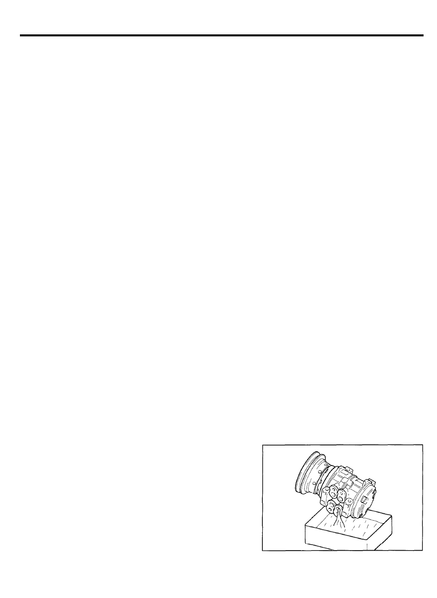
Checking and Adjusting a Used Compressor
The compressor oil should be checked in the following order:
1.
After the oil return operation, stop the engine, discharge the
refrigerant and then remove the compressor from the
vehicle.
2. Drain the oil from the system line connecting ports.
Oil is sometimes hard to drain out when the compressor
i s c o o l . D r a i n o i l w h i l e t h e c o m p r e s s o r i s w a r m
[maintained at 40°-50°C (104-122°F)].
9 7 - 2 5
AIR CONDITIONER SYSTEM
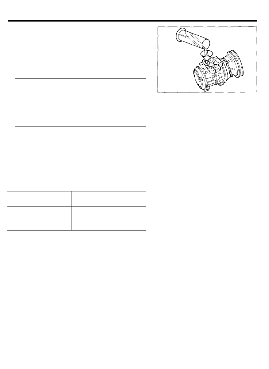
3. Measure the amount of the oil removed. If the amount is
less than 70cc (2.1 US fl oz, 2.5 Imp fl oz), some oil may
have leaked out. Conduct leak tests at the connections, and
if necessary, repair or replace faulty parts.
4. Check the purity of the oil and then adjust the oil level
following the procedure below.
1) If the oil is clean
Unit: cc (US fl oz, Imp fl oz)
Amount of oil drained
Adjusting procedure
More than 70 (2.3, 2.5)
Oil level is right.
Pour in same amount of oil
as was drained out.
Less than 70 (2.3, 2.5)
Oil level is low.
Pour in 70 (2.3, 2.5) of oil
2) If the oil contains chips or other foreign material flush
with the air conditioner system refrigerant and replace
the accumulator.
Then add the oil.
Adding Oil for Replacement Component Parts
When replacing the system’s component parts, be sure to add
the following amount of oil to the parts being replaced.
Component parts
Amount of oil
to be replaced
cc (US fl oz, Imp fl oz)
Evaporator core
Condenser
Accumulator
90 (3.0, 3.3)
30 (1.0, 1.1)
30 (1.0, 1.1)
9 7 - 2 6
AIR CONDITIONER SYSTEM
HOSE AND LINE CHECK
Check the heater and air conditioner hoses and lines for damage
due to interference with adjoining parts. If damage is major,
replace the affected parts.
Carefully check the hoses and lines, especially those located
close to moving parts or sharp panel edges.
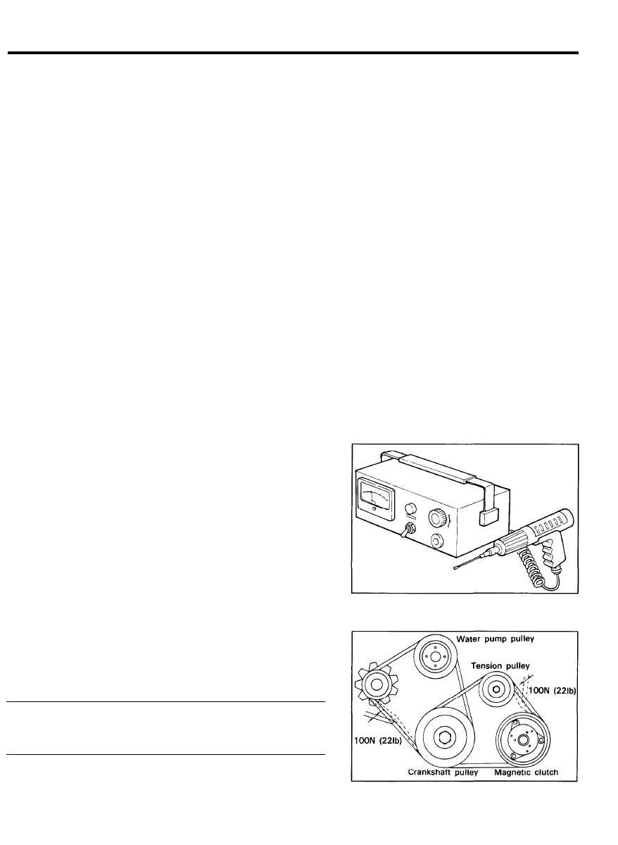
CHECKING REFRIGERANT LEAKS
Conduct a leak test with an electronic leak detector whenever
leakage of refrigerant is suspected and when conducting service
operations which are accompanied by disassembly or loosening
of connection fittings.
Electronic Leak Detector
The leak detector is a delicate device that detects small amounts
of halogen. In order to use the device properly, read the
manuals supplied by the manufacturer to perform the
specified maintenance and inspections.
If a gas leak is detected, proceed as follows:
1.
2.
3.
4.
Check the torque on the connection fitting and, if necessary,
tighten to the proper torque, Check for leakage with the leak
detector.
If leakage continues even after the fitting has been
retightened, discharge the refrigerant from the system,
disconnect the fitting, and check the seat for damage.
Replace fitting, even if the damage is slight.
Check compressor oil and add oil if required.
Charge the system and recheck for leaks. If no leaks are
found, evacuate and charge the system.
OFF-SEASON MAINTENANCE
In the off-season, turn the compressor on for 10 minutes at least
once a month and run the engine at idle.
Check the compressor belt for proper tension.
Belt deflection
Drive belt.. . . . . . . . . . . . . . . . . 9.0-10.4 mm (0.35-0.40 in.)
A/C compressor belt.. . . . . . . . . . . . . . . . . . . . . . 8.0-10.0 mm
AIR CONDITIONER SYSTEM
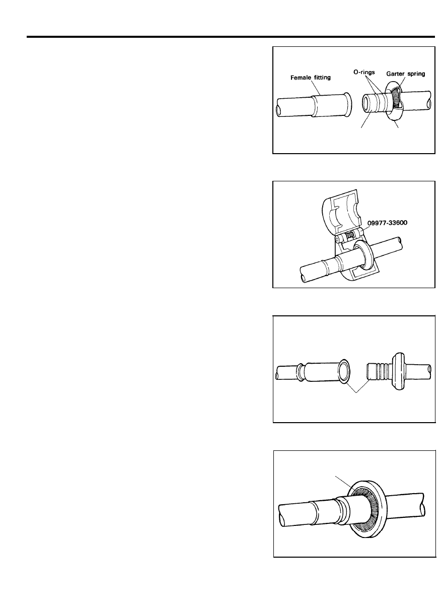
SPRING LOCK COUPLING
DISASSEMBLY
CAUTION
Discharge the system before disconnecting a coupling.
1.
Install the special tool, 09977-33600 (A/B) on the coupling.
2. Push the special tool into the cage opening to release the
female fitting from the garter spring.
3. Pull the male and female fittings apart.
4. Remove the tool from the spring lock coupling.
ASSEMBLY
1. Check for a missing or damaged garter spring.
Remove the damaged spring with a small hooked wire. Install
a new spring if damaged or missing.
2.
After cleaning the fittings, installing new O-rings. Lubricated
with clean refrigerant oil, Assemble the fitting together by
pushing with a slight twisting motion.
3.
To ensure engagement, visually check that the garter spring
is over the flared end of the female fitting.
Male fitting
Cage
Clean fitting
Garter spring
9 7 - 2 8
AIR CONDITIONER SYSTEM
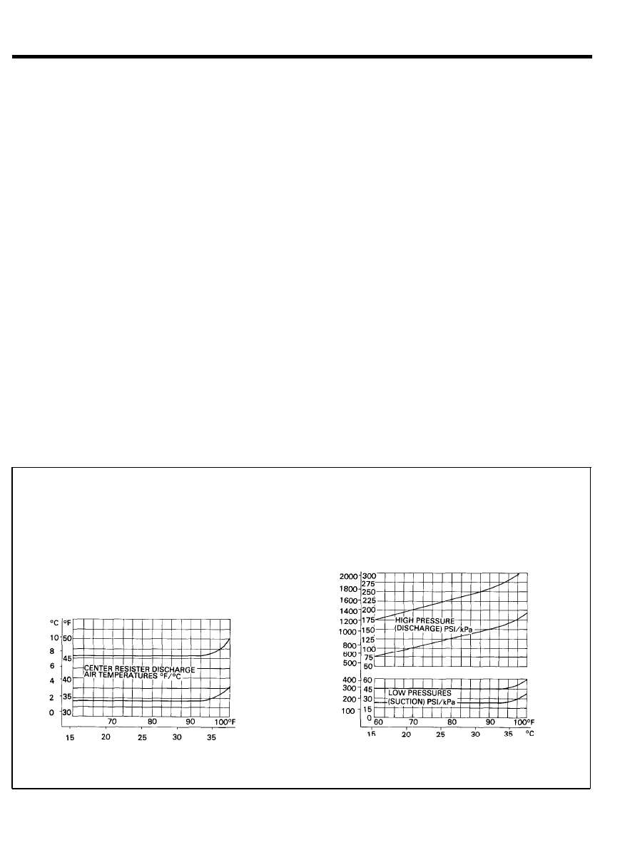
REFRIGERANT SYSTEM PERFORMANCE
EVALUATION
The best way to diagnose a problem in the refrigerant
system is to note the system pressures (shown by the
manifold gauges) and the clutch cycle rate and times.
Then, compare the findings with the charts (Figures 1
and 2).
o
The system pressures are low (compressor suction)
and high (compressor discharge).
o Clutch cycle times are the lengths of time (in
seconds) that the clutch is ON and OFF.
The following procedure is recommended for achieving
accurate diagnosis results in the least amount of time.
1. Connect a manifold gauge set.
NOTE:
The test conditions, specified at the top of each
chart, must be met to obtain accurate test results.
2.
As soon as the system is stabilized, record the high
and low-pressures as shown by the manifold
gauges.
3. Determine the clutch cycle time.
4. Record clutch off time in seconds.
5. Record clutch on time in seconds.
6. Record center register discharge temperature.
7. Determine and record ambient temperatures.
8. Compare test readings with the applicable chart.
(Figures 2 and 3)
o
Plot a vertical line for recorded ambient temperature
from scale at bottom of each chart to top of each
chart.
o Plot a horizontal line for each of the other test
readings from scale at LH side of appropriate chart.
If the point where the two lines cross or each of the
charts falls within the band of acceptable limits, the
system is operating normally. If the lines cross outside
the band on one or more of the charts, there is a
problem and the specific cause must be determined.
this is easily done by using the Refrigerant System and
Clutch Cycle Timing Evaluation chart (Figure 3).
Refer to the following five system operating conditions
indicated by where the lines cross on the charts.
o System high (discharge) pressure is high, low, or
normal.
o System low (suction) pressure is high, low, or
normal.
o
Clutch cycle rate is fast, slow, or the clutch runs
continuously.
IMPORTANT TEST REQUIREMENTS
The following test conditions must be established to obtain
accurate clutch cycle rate and cycle time readings.
o Run engine at 1500 rpm for 10 minutes.
o Operate A/C system on max A/C (recirculating air)
o Run blower at max speed.
o Stabilize in temperature 70°F to 80°F (21°C to 22°C)
NORMAL CENTER REGISTER
DISCHARGE TEMPERATURES
AMBIENT TEMPERATURES
AMBIENT TEMPERATURES
NORMAL FIXED ORIFICE TUBE CYCLING CLUTCH
REFRIGERANT SYSTEM PRESSURES
Fig.1 Normal Fixed Orifice Tube Refrigerant System Pressure/Temperature Relationships
9 7 - 2 9
AIR CONDITIONER SYSTEM
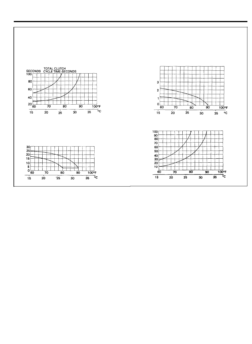
IMPORTANT TEST REQUIREMENTS
The following test conditions must be established to
obtain accurate clutch cycle rate and cycle time readings.
o Run engine at 1500 rpm for 10 minutes.
o Operate A/C system on max A/C (recirculating air)
o Run blower at max speed.
o
Stabilize in temperature 70°F to 80°F (21°C to 22°C)
NORMAL CLUTCH
SECONDS
OFF TIME-SECONDS
AMBIENT TEMPERATURES
NORMAL CLUTCH CYCLE RATE MINUTE
CYCLES/MINUTE
NORMAL CLUTCH
SECONDS
ON TIME-SECONDS
AMBIENT TEMPERATURES
Fig. 2 Normal Fixed Orifice Tube Refrigerant System Clutch Cycling Timing Rates
o Clutch on time is long or short.
o
Clutch off time is long or short.
Match these conditions to the conditions shown in the
five columns toward the left in the System Pressure and
Clutch Cycle Timing Evaluation chart (Figure 2). All five
system conditions will be indicated on one line. The
most likely component or components causing the
problem are listed in the column at the RH side of the
chart.
Example:
o High (discharge) pressure is low.
o Low (suction) pressure is normal.
o Clutch cycle rate is very fast.
o Clutch on time is very short.
o Clutch off time is very short.
The component causing the problem is the clutch
cycling pressure switch. The cycling range is too close.
Replace the switch and recheck the system.
Example:
o High (discharge) pressure is normal to low.
o Low (suction) pressure is normal.
o Clutch cycle rate is fast.
o Clutch on time is short.
o Clutch off time is short.
The component causing the problem is the evaporator
core. Airflow is restricted, indicating debris entering
through the cowl air inlet and plugging the core.
The condition can also be detected by checking the
center register discharge temperature. An abnormally
low temperature would mean air is spending more time
in the evaporator and is very cold when discharged,
although the volume is not enough to cool the vehicle
properly.
At the bottom of the chart (Figure 3). additional cause
components are listed for poor compressor operation or
a damaged compressor condition.
9 7 - 3 0

AIR CONDITIONER SYSTEM
The two diagnosis charts which follow Figure 3 provide
the most direct and sure way to determine the cause
of any problem in a poorly performing refrigerant
system. These charts are titled:
o Insufficient or No A/C Cycling-Fixed Orifice Tube
Cycling Clutch System (Test Steps A1 through A11).
o
Compressor Clutch Circuit Diagnosis (Test Steps B1
through B11)
After servicing and correcting a refrigerant system
problem, take additional pressure readings and observe
the clutch cycle rate while meeting the conditional
requirements (Figure 34) to ensure that the problem has
been corrected.
In ambient temperatures above 38°C (100°F), the
compressor clutch will not normally cycle off and in
many instances, the clutch will not cycle off when
temperatures are above 32°C. (90°F) This will depend
on local conditions and engine/vehicle speed. Also,
clutch cycling will normally not occur when the engine
is operating at curb idle speed. If the system contains
no refrigerant or is extremely low in refrigerant, the
clutch will not engage for compressor operation. A rapid
cycling compressor clutch is usually and indication that
the system is low on refrigerant. Refer to Insufficient
or No A/C Cooling-Fixed Orifice Tube Cycling Clutch
System Diagnosis chart.
9 7 - 3 1
AIR CONDITIONER SYSTEM
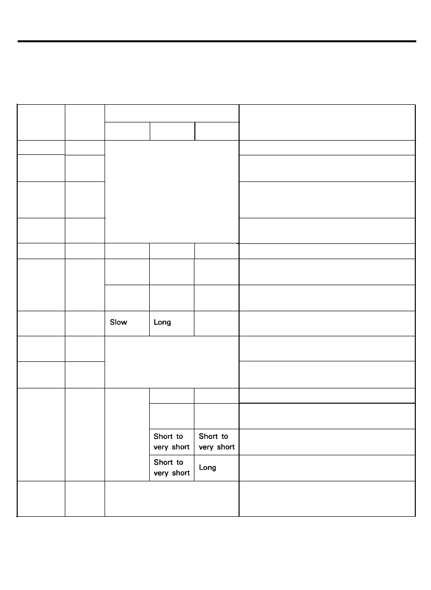
REFRIGERANT SYSTEM PRESSURE AND CLUTCH CYCLE TIMING EVALUATION CHART
NOTE
Normal system conditional requirements must be maintained to properly evaluate retrigerant system pressures.
Refer to charts applicable to system being tested.
High
(Discharge)
pressure
Low
(suction)
pressure
Clutch cycle time
Component-Causes
Rate
ON
OFF
Condenser-Inadequate Airflow
Engine overheating
High
Normal
to high
Normal
High
High
Normal
to High
Continuous run
Air in system
refrigerant overcharge(a)
Humidity or ambient temp very high(b)
Fixed orifice tube-Missing.
O-rings Leaking/Missing
Normal
High
Normal
High
Slow
Long
Long
Clutch cycling switch-High Cut-in
Moisture in refrigerant system.
Excessive refrigerant oil.
Slow or
Long or
no cycle
continuous
Fast
Short
Normal or
no cycle
Normal
Normal
Short
Clutch cycling switch-
Low Cut-in or High Cut-Out
Clutch cycling switch-
Low cut-out
Long
Normal
Normal
to low
Low
High
Normal
to high
Compessor-Low Performance
Continuous run
A/C suction line-Partially Restricted
or Plugged(c)
Normal
to low
Short
Normal
Evaporator-Low Airflow
Condenser, fixed orifice tube, or A/C
liquid line-Partially Restricted or Plugged
Short to
very short
Normal to
long
Normal
to low
Normal
Fast
Low refrigerant charge
Evaporator core-Partially Restricted or Plugged
A/C suction line-Partially Restricted or
Plugged.(d).
Clutch cycling switch-Sticking Closed
Normal
to low
Continuous run
Low
9 7 - 3 2

AIR CONDITIONER SYSTEM
High
Low
Clutch cycle time
(Discharge) (Suction)
Component-Causes
pressure
pressure
Rate
ON
OFF
Low
Normal
Erratic operation
or compressor not
running
Very
fast
-
Very
short
-
Very
short
-
Clutch cycling switch-Cycling Range Too Close
Clutch cycling switch-Dirty Contacts or Sticking
Open.
Poor connection at A/C clutch connector or
clutch cycling switch connector.
A/C electrical circuit erratic-See A/C Electrical
Circuit Wiring Diagram
Additional possible causes
associated with inadequate compressor operation
o Compressor clutch slipping. o Loose drive belt
o Clutch coil open-Shorted or loose mounting
o Control assembly switch-Dirty contacts or sticking open
o Clutch wiring circuit-High resistance. Open or blown fuse
Additional possible causes
associated with a damaged compressor
o Clutch cycling switch-Sticking closed or compressor clutch seized
o Suction accumulator drier-Refrigerant oil bleed hole plugged
o Refrigerant leaks
1)
Compressor may make noise on initial start-up. This condition can be caused by excessive liquid refrigerant.
2) Compressor clutch may not cycle in ambient temperatures above 80°F depending on humidity.
3)
Low pressure reading will be normal, to high if the pressure readings are taken at the accumulator and if
the restriction is down stream of the service access valve.
4) Low pressure reading will be low if pressure readings are taken near the compessor and the restriction is
upstream of the service access valve.
Fig.3 Refrigerant System Pressure and Clutch Cycle Timing Evaluation-Fixed Orifice Tube Cycling Clutch System.
9 7 - 3 3
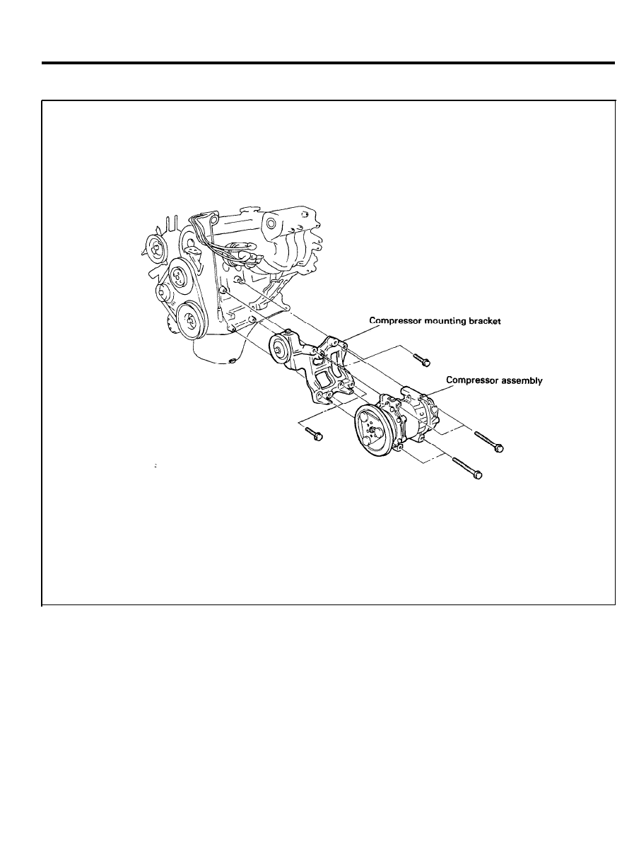
COMPRESSOR ASSEMBLY
C O M P R E S S O R
COMPONENTS
REMOVAL AND INSTALLATION
1. Remove the distributor assembly.
2. Loosen the tension pulley and then remove the belt.
3. Discharge the refrigerant.
4. Disconnect the magnetic clutch connector,
5. Remove the discharge hose and suction hose.
6. Remove the compressor from the compressor bracket
assembly.
7. Installation is the reverse of removal.
9 7 - 3 4
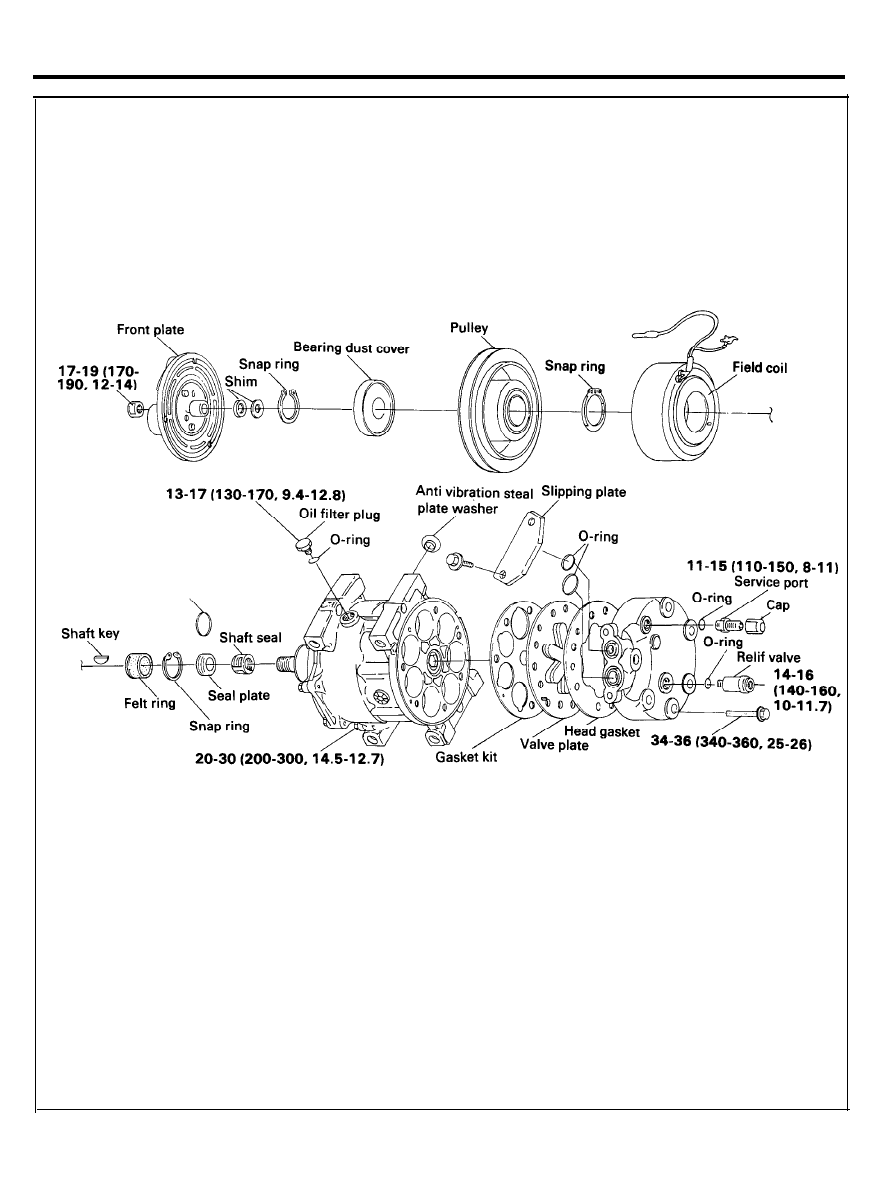
COMPRESSOR ASSEMBLY
COMPONENTS
TORQUE : Nm (kg.cm, Ib.ft)
9 7 - 3 5
COMPRESSOR ASSEMBLY
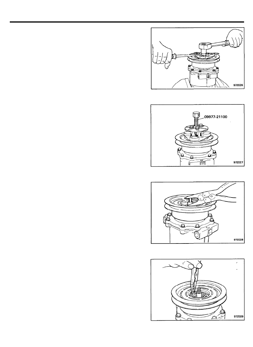
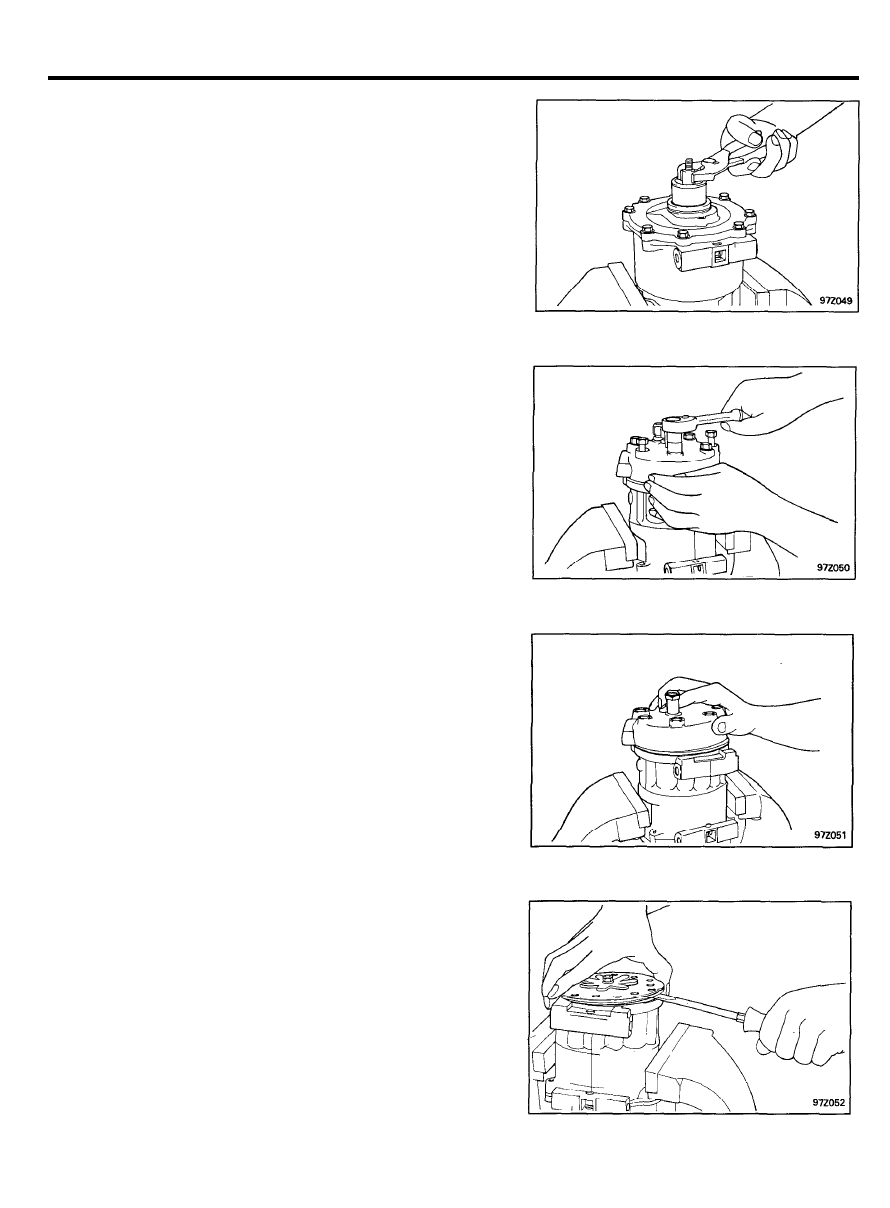
DISASSEMBLY
CLUTCH FRONT PLATE
Removal
1. Removal of U-NUT
1) Temporarily install two M6 bolts, 25 mm (.98 in.) or
longer, in the bolt holes of the clutch front plate.
NOTE:
Make sure the ends of the bolts do not contact the
front housing.
2) Use two box-end wrenches to hold the bolts (so as to
prevent the clutch front plate from turning). Then remove
the nut.
3) Remove the clutch front plate from the shaft.
2. Remove the clutch front plate using the clutch front plate
puller (09977-21110).
1) Align the puller center bolt on the compressor shaft.
2)
Hand tighten the three puller bolts into the thread holes.
3) Turn the center bolt clockwise with the socket until the
clutch front plate is loosened.
3. Remove the clutch shims.
4. Remove the bearing dust cover.
5 . Remove the external front housing snap ring using snap ring
pliers.
9 7 - 3 6
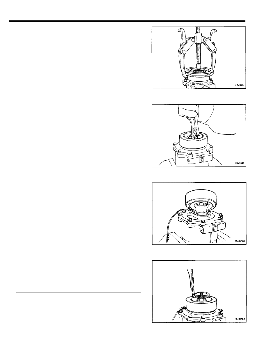
COMPRESSOR ASSEMBLY
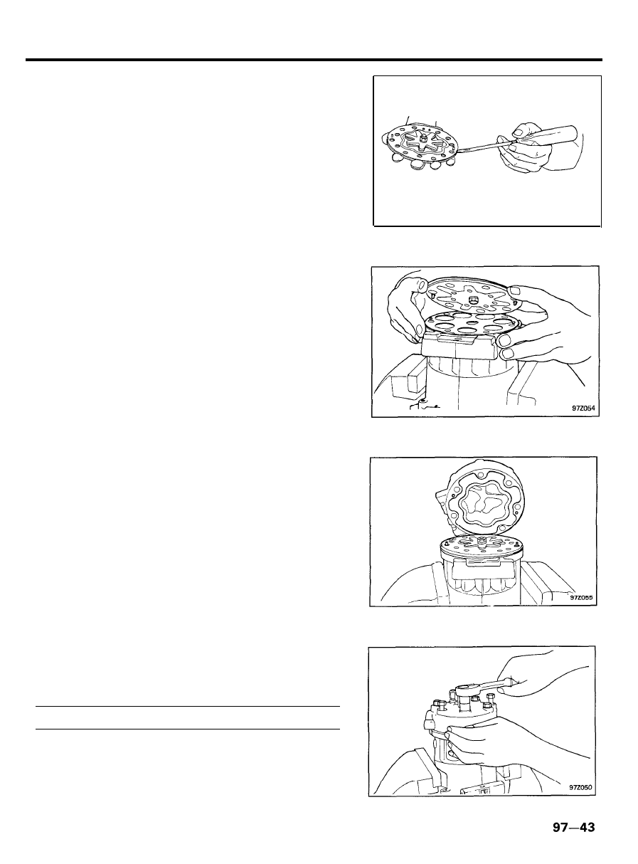
6.
Using the puller, remove the rotor pulley assembly.
7. Loosen the clutch lead wire from the clip on top of the
compressor front housing.
8.
Using snap ring pliers, remove the snap ring and field coil.
INSTALLATION
1.
The coil flange protrusion must match the hole in the front
housing to prevent coil movement and to correctly position
the lead wire.
2. Place the coil snap ring into position using pliers.
NOTE
Make sure the snap ring is firmly in place.
3. Tighten the wire clip
Torque . . . . . . . . . . . . 20-25 Nm (200-250 kg.cm, 14-18)
9 7 - 3 7
COMPRESSOR ASSEMBLY
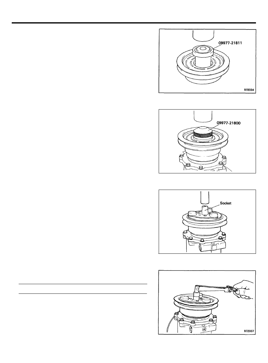
4.
5 .
6.
7.
8.
9.
Install the pulley assembly using the special tool. (09977-
21811).
NOTE
1) Press in the rotor bearing outer race.
2) After installation, rotate the pulley assembly and check
for proper installation.
Reinstall the external bearing snap ring with pliers.
NOTE
When installing the snap ring, be careful not to scratch the
surface of the bearing with pliers.
Using the special tool (09977-21800) install the bearing
dust cover,
NOTE
After installation, rotate the clutch pulley. Check that
there is no contact between the cover and front housing.
Reinstall the clutch spacer shims.
NOTE
Check that the original clutch shims are in place on the
compressor shaft.
Align the front plate key-way to the compressor shaft key.
Then install the front plate using a socket.
With the special tool, (09977-21110). tighten the U-Nut to
specifications.
Torque . . . . . . . . . . . . . . 17-19 Nm (170-190, 12-14 Ib.ft)
9 7 - 3 8
COMPRESSOR ASSEMBLY
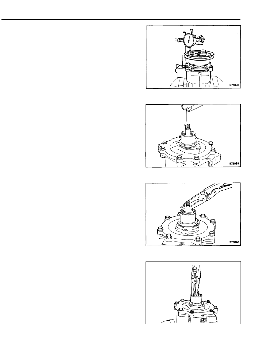
10. Check the air gap and clutch engagement.
1) Place a dial gauge onto the clutch front plate.
2)
Apply 8V DC to the coil and check clutch engagment. The
air gap (readings before and after the engagement)
should be as follows.
Air gap between the front plate and clutch rotor: 0.4-0.8
mm (0.016 - 0.032 in.)
3)
If the air gap is out of specifications, remove the U-Nut
and front plate.
4) Replace the shims with ones of different thickness to
adjust the air gap.
SHAFT SEAL ASSEMBLY
Removal
1.
Remove the shaft key by lightly tapping it with a screw driver
and plastic hammer.
2.
Using the snap ring pliers, insert the tool points into the two
holes of the felt ring metal retainer and lift out the felt ring.
3.
Remove the shaft seal seat retaining snap ring with pliers.
9 7 - 3 9
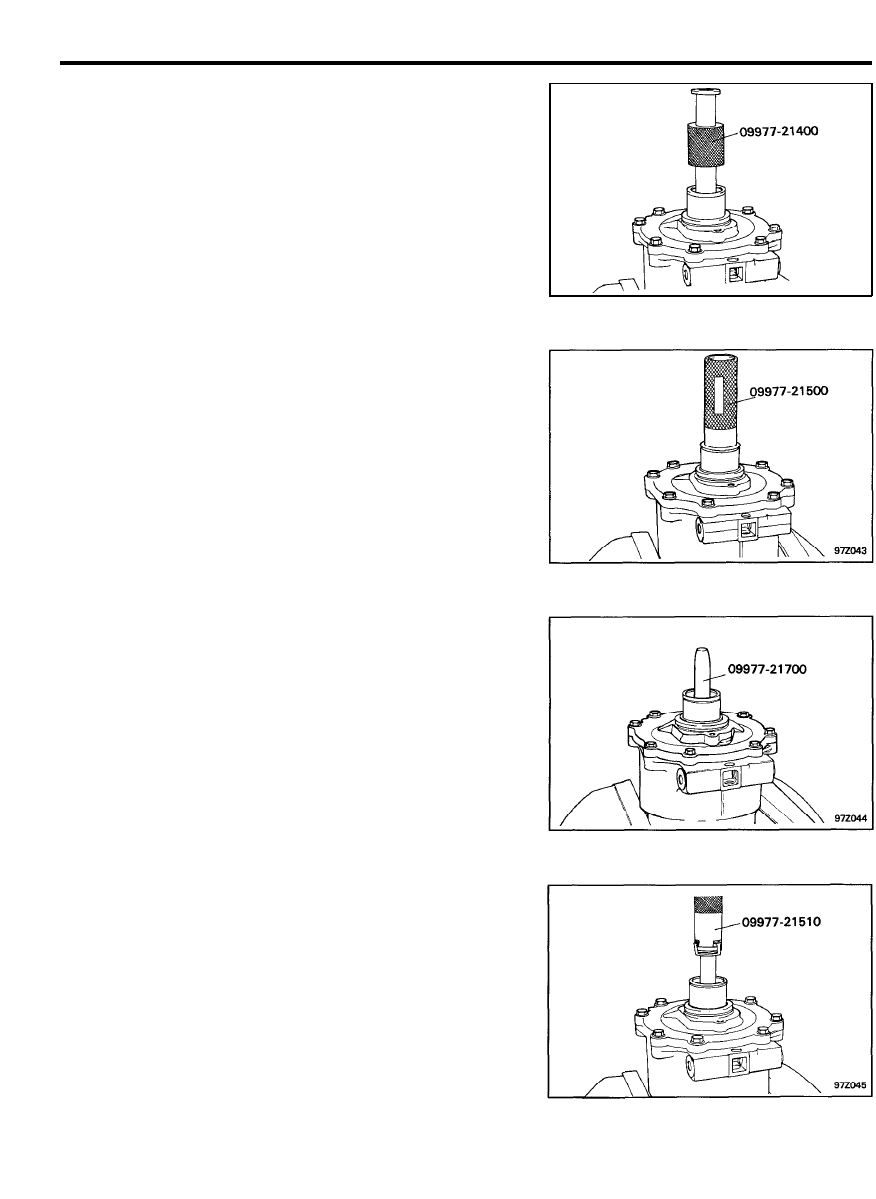
COMPRESSOR ASSEMBLY
4. Insert the seal seat remover (09977-21400) against the
seal plate and twist the seal seat remover until it engages
the plate and lift out.
5. Insert the shaft seal remover (09977-21500) against the
seal assembly. Press down against the seal spring and twist
the tool until it engages the slots of the seal cage. Lift out
the seal assembly.
INSTALLATION
The shaft seal assembly should never be reused.
Never re-use any parts of the assembly.
Replace the complete assembly.
Make sure all foreign substances are thoroughly removed from
the compressor shaft and front housing.
Do not touch the surface of the seal while handling the seal
assembly.
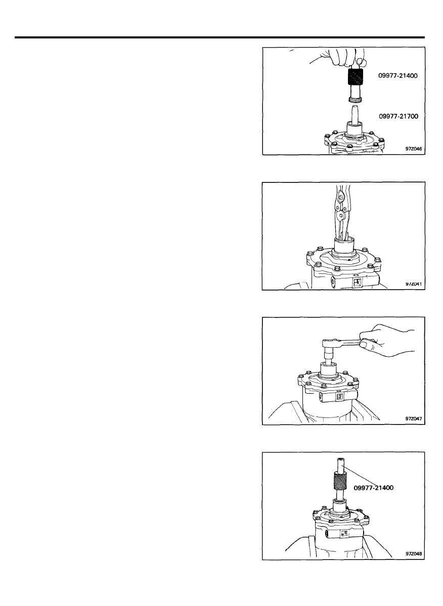
1. Insert the shaft seal guide (09977-21700) over the
compressor shaft. Apply refrigerant oil onto the outer surface
of the shaft seal guide.
2.
Clean the seal surface and O-ring with an air nozzle. Apply
clean refrigerant oil to the seal surface.
Place the slots of the shaft seal remover (09977-21510)
into the new seal assembly. Firmly press and twist clockwise,
until the seal assembly is engaged. Twist the tool in the
opposite direction to disengage the tool from the seal cage.
Remove the tool.
9 7 - 4 0
COMPRESSOR ASSEMBLY
3. Coat the seal retainer with clean refrigerant oil.
Use the tool to install. Press lightly against seal.
4. Remove the shaft seal guide.
5. Install the snap ring.
NOTE
The beveled edge faces outward from the compressor and
the flat side faces towards the compressor.
6. Check for refrigerant leakage.
1 ) Install the shaft nut onto the compressor shaft and rotate
the compressor shaft several times using a socket.
2) Charge the compressor and check for leakage at the
shaft seal using a leak detector.
7.
Insert a new felt ring into the front housing and press evenly
with the special tool (09977-21400).
9 7 - 4 1
COMPRESSOR ASSEMBLY
8. Using pliers, press the key into place. Be careful not to
damage the compressor shaft when installing.
C Y L I N D E R H E A D A N D V A L V E P L A T E
R E M O V A L
1. Remove the six cylinder head cap screws using a 13 mm
socket.
2.
Use a small plastic hammer and a gasket scraper to tap the
outer edge of the cylinder head until it is loose from the valve
plate. (The cylinder head gasket normally sticks to the valve
plate.)
Do not scratch the cylinder head or valve plate when
removing.
3.
Position the gasket scraper between the outside edge of the
valve plate and the cylinder block and tightly tap the valve
plate loose.
9 7 - 4 2
COMPRESSOR ASSEMBLY
4. Using the gasket scraper, remove the cylinder and head
gaskets.
Do not damage the cylinder block or valve plate surfaces.
INSTALLATION
1. Coat the valve plate with refrigerant oil and install the
cylinder block gasket.
2. Align the valve plate locating pins to the pin holes in the
block and position the valve plate.
3. Coat the valve plate with refrigerant oil and install the
cylinder head gasket.
4. Align the valve plate locating pins to the pin holes in the
cylinder head and position the cylinder head.
Tighten the six bolts in the cylinder head with a torque
wrench.
Torque . . . . . . . . . 34-36Nm (340-360 kg.cm, 25-26 Ib.ft)
COMPRESSOR ASSEMBLY
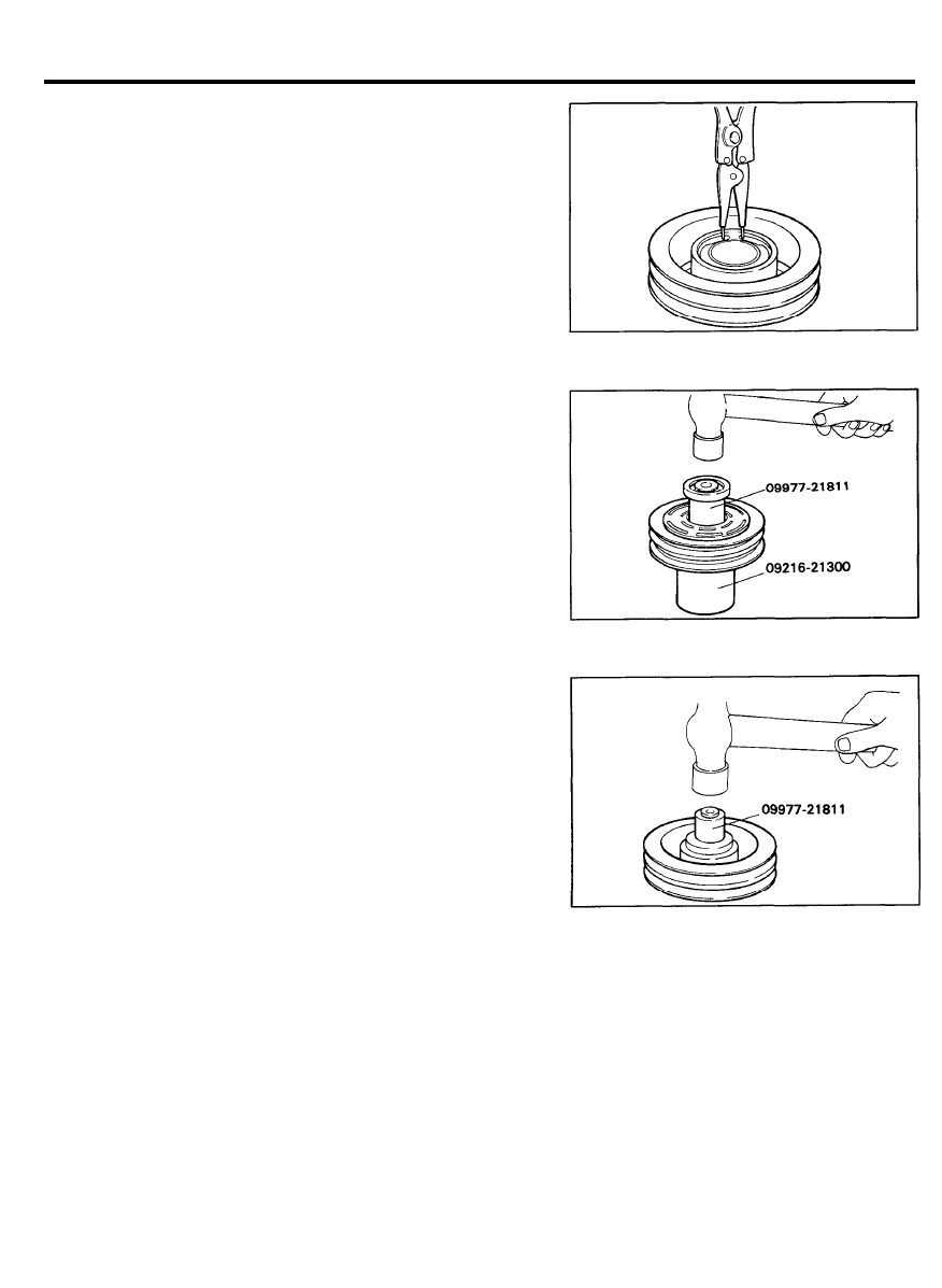
Rotor Pulley Bearing
Removal and Installation
1. Remove the bearing snap ring.
2.
Using the special tools, (09977-21811 and 09216-21300)
remove the bearing.
3. Using the special tool, (09977-21811) install the bearing.
9 7 - 4 4
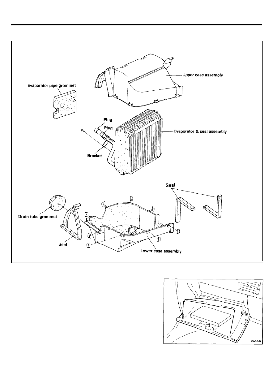
EVAPORATOR ASSEMBLY
EVAPORATOR
COMPONENTS
REMOVAL AND INSTALLATION
1. Discharge the refrigerant from the lines system.
2. Disconnect the suction and liquid lines.
3. Remove the grommet cover.
4. Remove the console assembly.
5. Remove the glove box assembly.
9 7 - 4 5
EVAPORATOR ASSEMBLY
6. Remove the main lower crash pad, lower crash pad center
facia panel and lower crash pad center skin.
7. Remove the blower assembly.
8. Remove the evaporator assembly.
9. Installation is the reverse of removal.
INSPECTION
1. Check for damage to the evaporator fins.
2. Check for a damaged or collapsed drain hose.
3. Check for peeling or cracking of the insulation.
9 7 - 4 6
CONDENSER ASSEMBLY
CONDENSER
COMPONENTS
ON-VEHICLE INSPECTION
1. Check the condenser fins for restriction or damage.
If the fins are restricted, wash them with water and dry with
compressed air. If the fins are bent, straighten with a
screwdriver or fin straightener.
CAUTION
Be careful not to damage the fins.
2. Check the condenser fittings for leakage.
9 7 - 4 7
CONDENSER ASSEMBLY
REMOVAL
1. Lift the hood.
2. Discharge the refrigerant from the system.
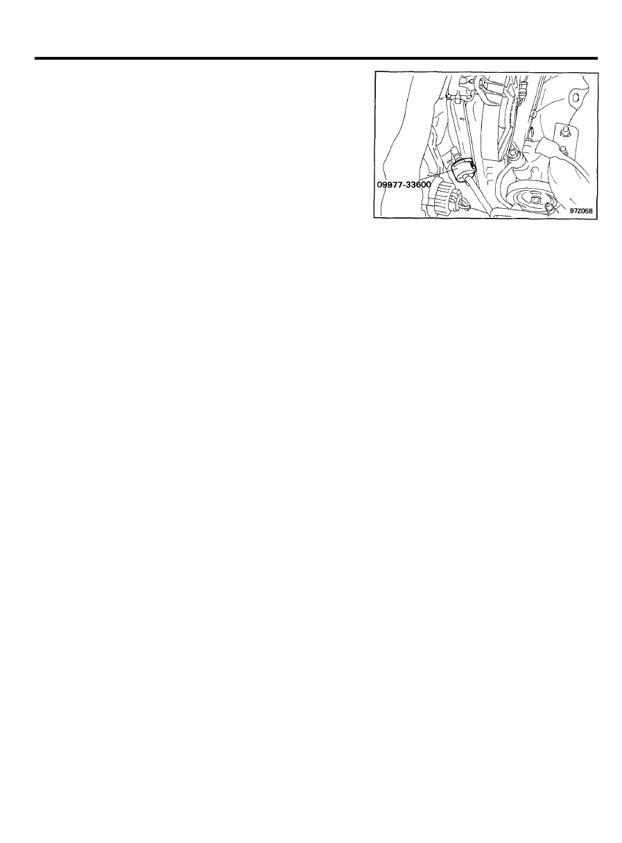
3.
Disconnect the discharge line from the condenser inlet fitting
using the special tool. (09977-33600)
4. Remove the radiator grille.
5. Remove the radiator assembly.
6.
Disconnect the liquid line from the condenser outlet fitting.
INSTALLATION
1. Installation is reverse of removal.
2. If the condenser is replaced, add refrigerant oil to the
compressor (1.8 US fl oz, 1.9 Imp fl oz)
3. Evacuate, charge and test refrigeration system.
9 7 - 4 8
CONDENSER FAN & RELAY
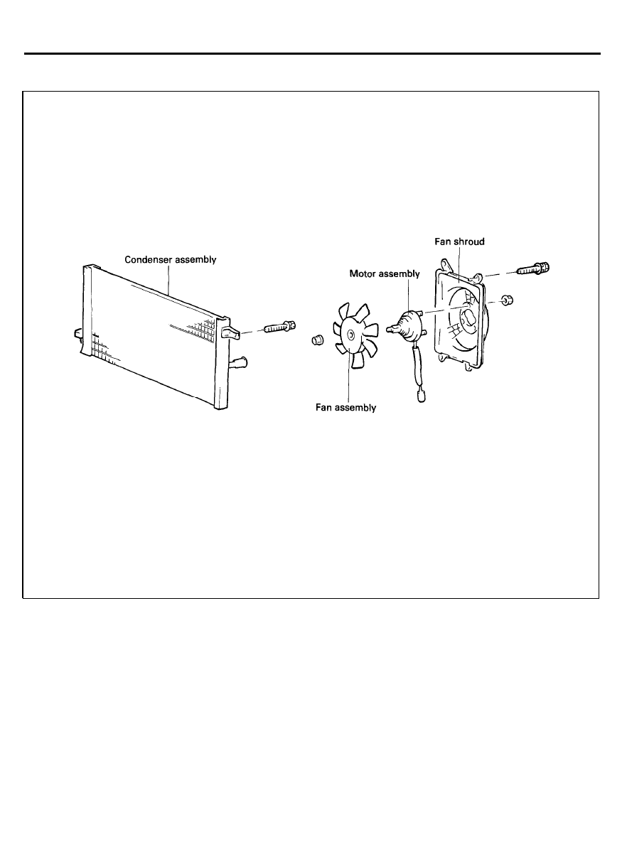
CONDENSER FAN ASSEMBLY
ON-VEHICLE INSPECTION
1. Check the condenser fan for restrictions or damage.
2. Check the harness connection.
REMOVAL AND INSTALLATION
1. Disconnect the battery ground cable.
2. Disconnect the connector from the A/C harness.
3. Remove the fan assembly.
4. Installation is the reverse of removal.
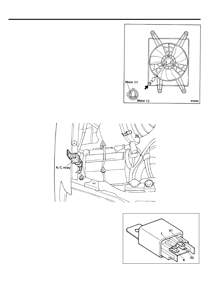
INSPECTION
1.
Using an ohmmeter, check that there is continuity between
terminals L and B.
RELAY
INSPECTION
1. Using an ohmmeter, check to be sure that there is no
continuity between terminals L and B.
2. Apply 12 volts across Terminals S1 and S2 then check
continuity between terminals L and B.
Replace if necessary.
9 7 - 4 9
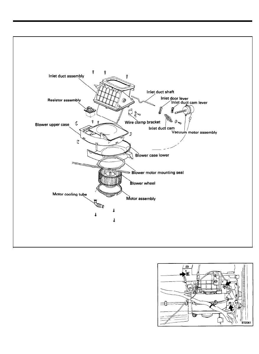
BLOWER ASSEMBLY
B L O W E R A S S E M B L Y
COMPONENTS
REMOVAL AND INSTALLATION
1. Remove the glove box housing cover assembly.
2. Remove the lower crash pad assembly.
3. Disconnect the resistor and blower motor connector.
4.
Pull out the blower unit and then disconnect the fresh/recirc
vacuum connector.
5. Installation is the reverse of removal.
9 7 - 5 0
BLOWER ASSEMBLY
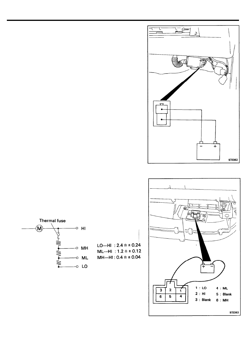
INSPECTION
1. Check for bending or abnormal deflection of the rotating
shaft of the blower motor assembly.
2. Check for cracking or deterioration of the packing.
3. Check for damage to the fan.
4. Check for damage to the blower case.
5. Check the operation of the inside/outside air selection
damper, and for damage.
6. Connect the blower motor terminals directly to the battery
and check that the blower motor operates smoothly.
7.
Next, reverse the polarity and check that the blower motor
operates smoothly in the reverse direction.
8.
Using an ohmmeter, check that there is continuity between
terminals 1 and 2.
If there is no continuity, replace the resistor.
9 7 - 5 1
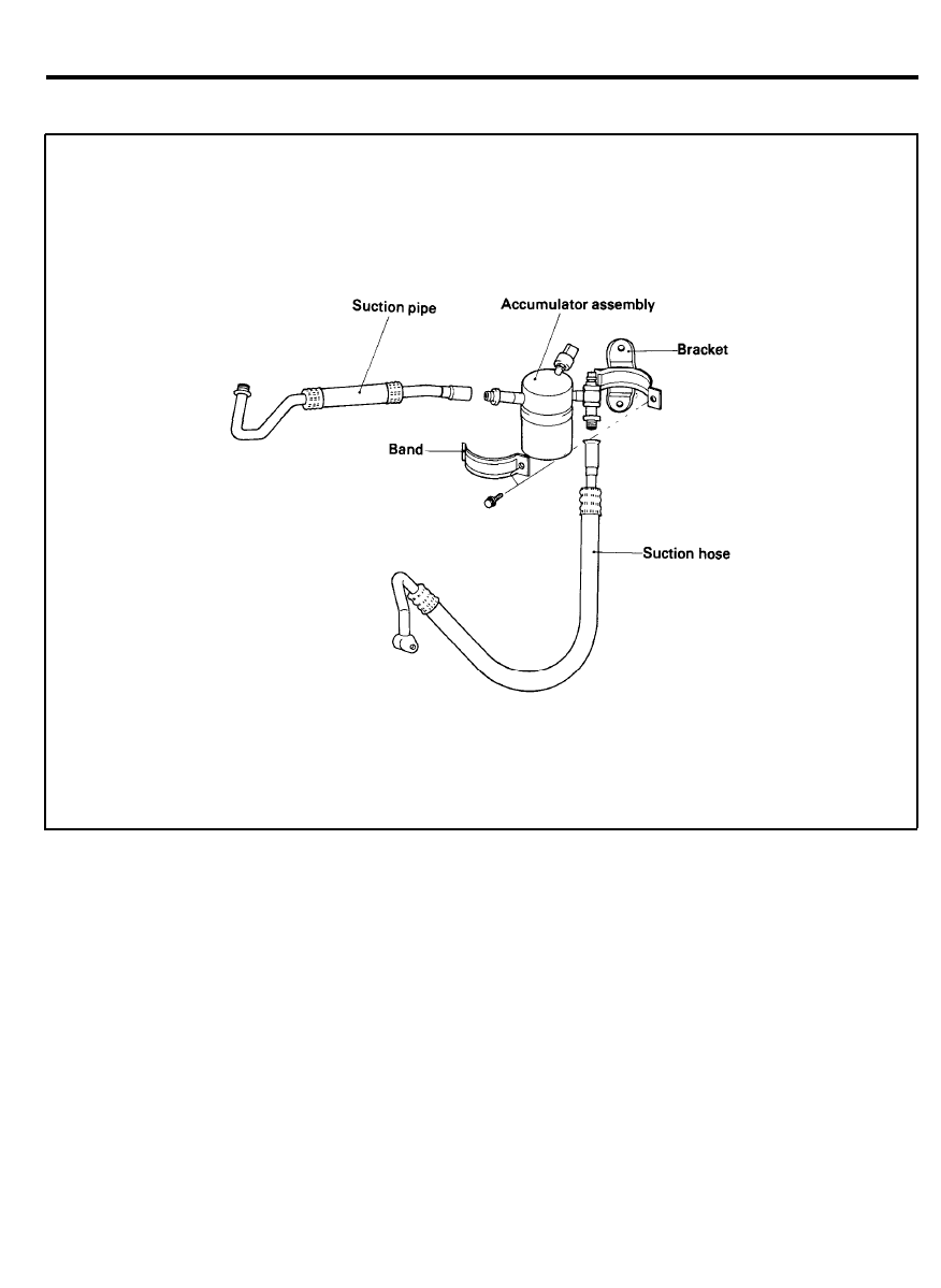
ACCUMULATOR ASSEMBLY
ACCUMULATOR
COMPONENTS
REPLACEMENT
It will be necessary to replace the accumulator for the following
reasons.
1. The accumulator is restricted, plugged or damaged.
2. The system has been left open for more than 24 hours.
(system completely discharged)
3. There is evidence of moisture in the system.
4. A component such as a condenser, evaporator core,
refrigerant line or a seized compressor is replaced.
NOTE:
It is not necessary to replace the accumulator when there
is a partial loss of refrigerant charge or a dent is found
in the outer shell of the accumulator.
9 7 - 5 2
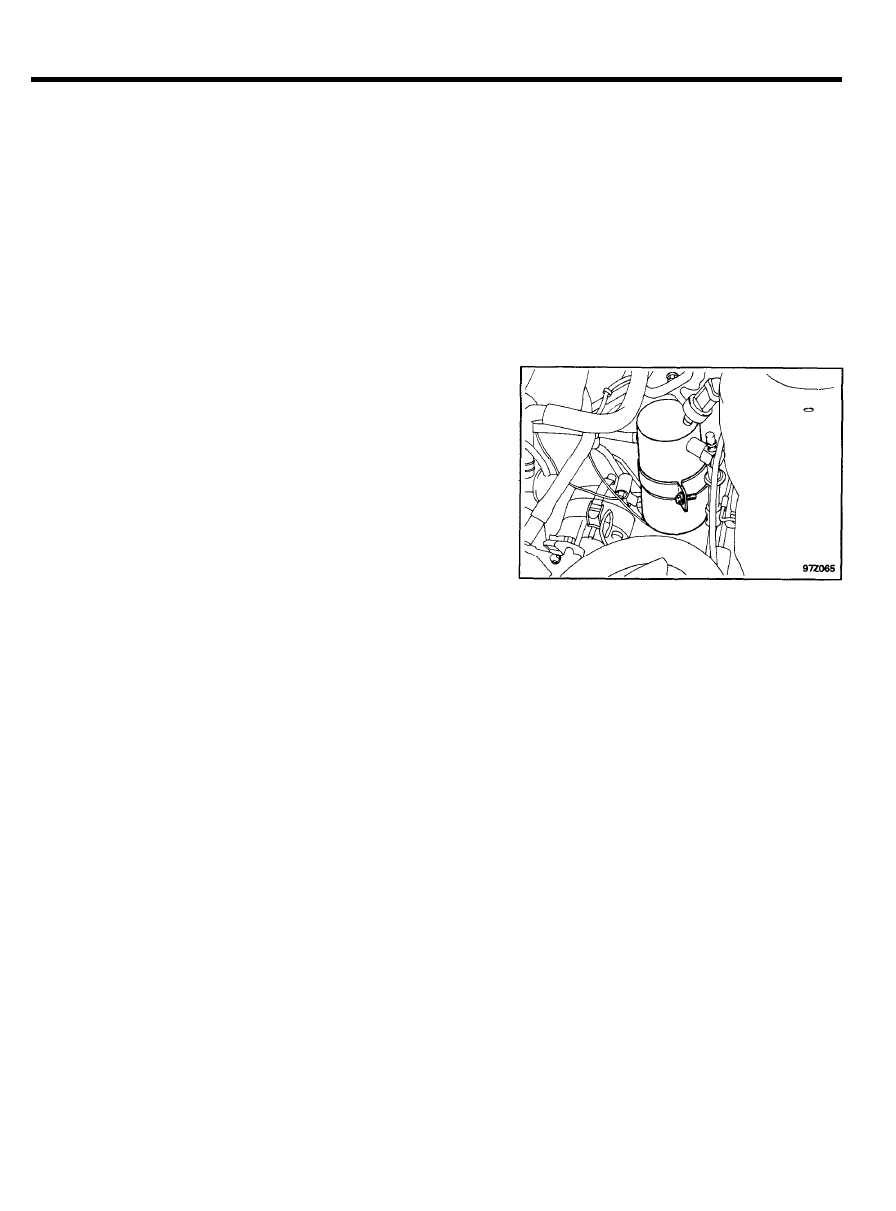
ACCUMULATOR ASSEMBLY
REMOVAL
1. Discharge the air conditioning system.
2. Disconnect the two suction line from the accumulator.
3. Disconnect the wiring harness.
4. Remove the accumulator from the bracket.
5. Remove the clutch cycling switch.
NOTE
Plug all open fittings immediately to keep moisture out of
the system.
INSTALLATION
1.
Install the accumulator in the bracket.
NOTE
Do not remove the plugs until ready for connection.
2.
3.
4.
5.
6.
7 .
Connect the liquid lines to the accumulator.
If the accumulator is replaced with a new unit, add 30cc of
compressor oil to the accumulator.
Install the clutch cycling switch.
Connect the wiring harness.
Charge the system.
Check for any refrigerant leaks.
9 7 - 5 3
Wyszukiwarka
Podobne podstrony:
19 Rear Air Conditioning
SR 8 Adaptive Air Conditioning ULA[1]
6 4 1%20Ventilation%20in%20Air conditioned%20Premises
0502 Refrigerant circuit Model 126 with air conditioning system
HEATER & AIR CONDITIONER
Audel Hvac Fundamentals, Air Conditioning, Heat Pumps And Distribution Systems (Malestrom)
Manual Air Conditioning
zestaw 19, AiR, Semestr 2, Grafika inżynierska, zadania grafika
Air Conditioning
Automatic Air Conditioning
Design Of Air Conditioning Ducts
Air conditioning sometimes does not work
SR 8 Adaptive Air Conditioning ULA[1]
6 4 1%20Ventilation%20in%20Air conditioned%20Premises
Chrysler voyager air conditioner fix ac
Air Conditioning Fault Finding
więcej podobnych podstron