
CRYOGENIC TREATMENT AND IT’S EFFECT
ON TOOL STEEL
T. Yugandhar, P.K. Krishnan
Tool Room
Nuclear Fuel complex
Hyderabad –500062
India
C.V. Bhaskar Rao and R. Kalidas
ZF & T
Nuclear Fuel complex
Hyderabad –500062
India
Abstract
Tools for presswork, powder compaction, seamless tube pilgering, extrusion
and metal cutting and metal sponge cutting (chisel) were subjected to cryo-
genic treatment. Each type of the above tool was studied in detail about its
performance versus the hardened and tempered tools. Then wherever the
function of the tools demanded high surface finish criterion, those tools were
subjected to hardening and tempering followed by surface coating method,
plasma ion deposition method, and nitriding by impregnation methods etc.
Keywords:
Tools steel, nitriding, cryogenic treatment
PROCESS
The process typically involves slowly cooling a mass of parts to – 196
◦
C,
holding them at this temperature for 30 h or more, then slowly heating
them back to ambient temperature. In case of steels, the benefits are usually
671

672
6TH INTERNATIONAL TOOLING CONFERENCE
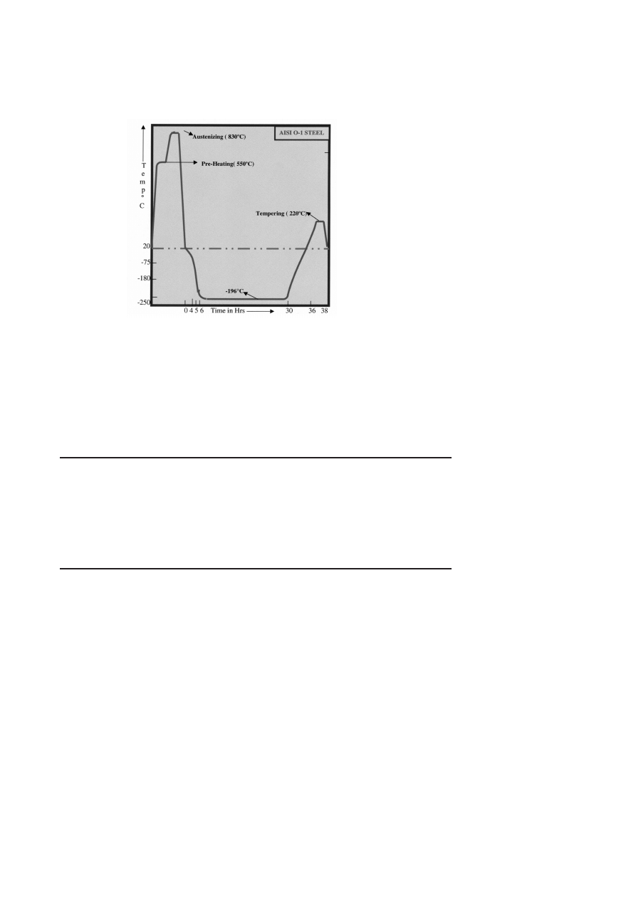
Figure 1.
A typical cryogenic treatment for tool steels.
attributed to the reduction or elimination of retained austenite from hardened
steel and accompanied by the precipitation of small finely dispersed carbides
(η-carbides) in the martensite. Figure 1 shows a typical cryogenic treatment
temperature sequence for tool steels.
PRESENCE OF RETAINED AUSTENITE IN TOOL
STEELS
Through hardening of steel involves heating the steel to a temperature
at which it becomes austenite and then cooling rapidly enough to produce
martensite, a hard and strong, but brittle structure. Tempering at moderately
elevated temperatures reduces this brittleness. Generally austenite phase
may be retained in small amounts in low-alloy steels and in appreciable
amounts in high-alloy steels, because of the austenite stabilizing effect of
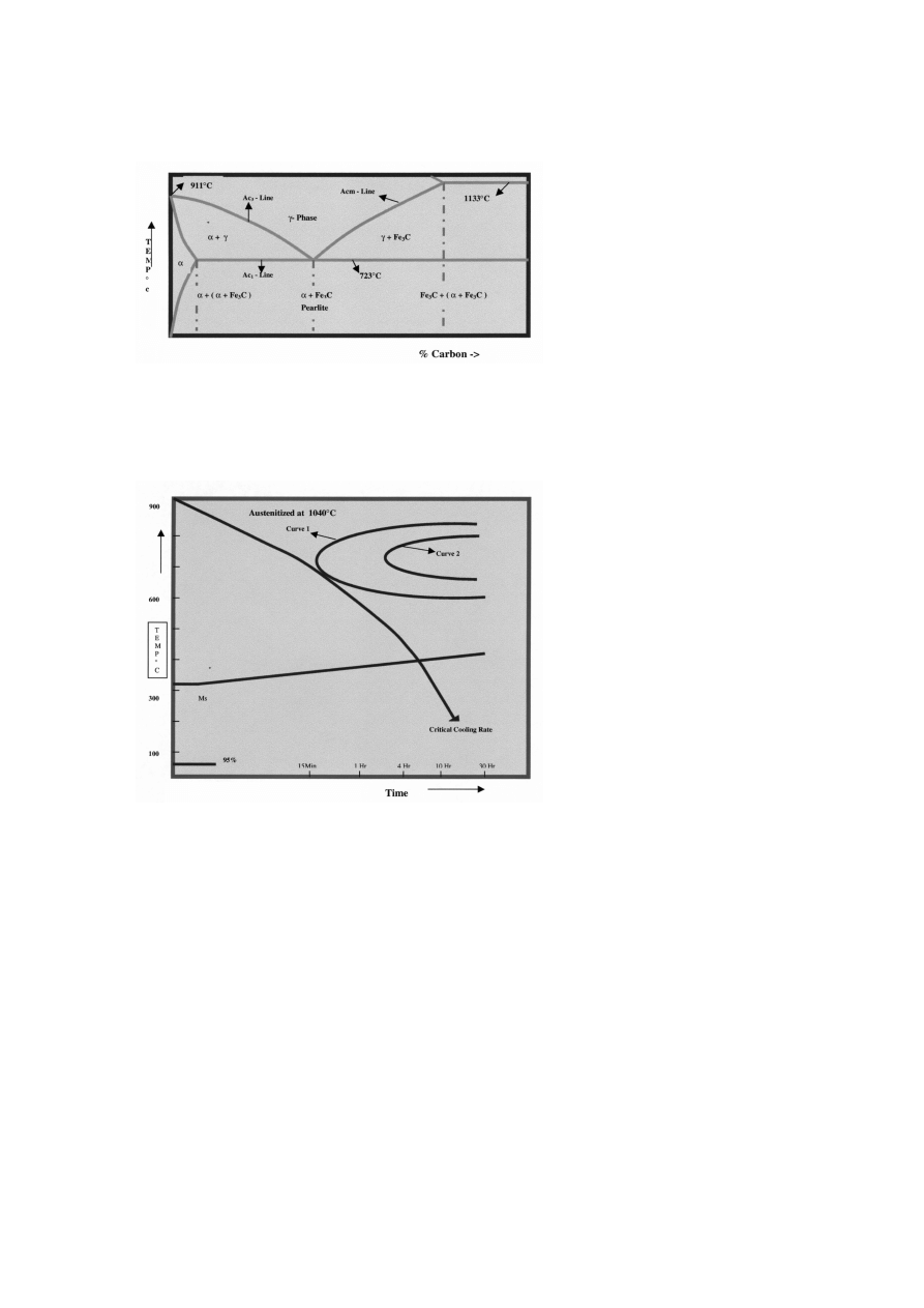
various alloying elements. The Fig. 2 shows the steel portion of the iron-
carbon diagram which describes how the room temperature structure of the
steel changes to austenite and the different critical temperature points where
these structural changes takes place. The TTT curve, Fig. 3, describes how
the austenite upon cooling is transformed into various phases like pearlite,
bainite, martensite and retained austenite at different cooling rates. The first
phase undergoes diffusion type transformation, the martensite phase under-
goes diffusionless transformation, while the bainite phase undergoes both
diffusion and diffusion less transformations. As shown in Fig. 3, the curve 1
Cryogenic treatment and it’s effect on tool steel
673
Figure 2.
Steel Portion of Iron-Carbon Diagram.
Figure 3.
T.T.T. Diagram For AISI H-12.

674
6TH INTERNATIONAL TOOLING CONFERENCE
gives the starting points of transformation while curve 2 gives the end points
of transformations at different temperatures. In view of the cryogenic treat-
ment it is more important to study the bottom portion of the TTT curve, to
have an idea about where the martensite transformation starts and ends. This
will in turn enable us to know how the austenite is retained. In general, the
martensite starting point is slightly above room temperature in most of the
tool steels. The transformation end point in some tool steels is well below the
room temperature, which leads to retaining some amount of austenite, The
retained austenite percentage depends on the chemical composition of the
tool steel and its hardening and quenching procedure. To arrest the retained
austenite transformation it is necessary to quench the tool steel not less than
its critical cooling velocity, and allow the tool steel to cool down to tempera-
ture well below the martensite transformation end point. Here, practically all
the austenite will be transformed into martensite. Some times this transfor-
mation is not complete, because the velocity of the tool steel quench is lower
than the required, or the temperature to which the steel is cooled is well above
the martensite transformation end point. treatment to optimize its service
quality, it should be comparable with the tool in which the transformation of
martensite is complete. The Ms and Mf temperatures for various steels can
be found out by using empirical formulas. Some manufacturers prescribes
the sub-zero treatment (not necessarily at cryogenic temperatures) between
quenching from austenitizing temperatures and tempering. Though the prop-
erly treated tools do not require subsequent cryogenic treatment, many users
attest to the superior performance of cryogenically treated tools.
TEMPERING AND ITS EFFECT ON CRYOGENIC
TREATMENT
Tempering the steel after quenching from austenitizing temperature to
the temperature lower than the A
c
1
temperature and soaking, relieves the
internal stress developed during quenching and improves the toughness by
the precipitation of carbides uniformly throughout the structure. In turn,
it reduces the carbon from both martensite and retained austenite. This
process enables the steel to lower its retained austenite partially, but not
completely even after the steel is subjected for suggested double tempering.
The only way to reduce the retained austenite percentage is by subjecting the
steel to cryogenic treatment (extended quench) immediately after quenching

Cryogenic treatment and it’s effect on tool steel
675
from austenitizing temperature. Also, it enhances the precipitation of η-
carbides during subsequent tempering. The η-carbides that form is uniformly
distributed throughout improved hardness, toughness, wear resistance and
resistance to fatigue cracking.
New time-temperature "rules" must be applied to the post cryogenic treat-
ment temper to obtain these benefits consistently. If traditional tempering
practice is followed the potential advantage of deep cryogenic treatment may
not be realizedcases, the net effect on properties could be negative.
ROLE OF CARBIDES
The present study is also important to the development of this technol-
ogy, where the results of practice focused on deep cryogenic treatment at
–196
◦
Cof AISI O-1, D-2 and H-12 tool steel. The study identified martensite
decomposition and precipitation of fine η-carbides as the main mechanisms
responsible for the beneficial effects of deep cryogenics.
Mechanical properties of the alloy tool steels subjected to cryogenic treat-
ment are optimized if -196
◦
C"extended quench" is followed with single
conventional temper. The implication is that the multiple tempers com-
monly incorporated in conventional heat treatments can be eliminated. The
precipitation of η-carbides in tool steel occurs only during the temper that
follows deep cryogenic treatment, and lengthens the tool life as the amount
of η-carbides increases. The amount of η-carbides that forms is directly
proportional to the tempering time and temperature. Typical heat treatment
cycle using cryogenic treatment can be seen in Fig. 4
CRYOGENIC TREATMENT AND ITS EFFECT ON
MECHANICAL PROPERTIES
Cryogenic treatment improves the mechanical properties like hardness,
wear resistance, toughness, and resistance to fatigue cracking. The possible
reasons for this improvement are as follows.
According to one theory of this treatment, transformation of retained
austenite is complete – a conclusion verified by X-ray diffraction mea-
surements.
Another theory is based on the strengthening of steels by the precip-
itation of submicroscopic carbides. An added benefit is said to be a

676
6TH INTERNATIONAL TOOLING CONFERENCE
Figure 4.
Typical heat treatment cycle using cryogenic treatment.
reduction in internal stresses in the martensite developed during car-
bide precipitation, which in turn reduces tendencies to micro-crack.
Table 1 shows, the wear resistance of different tool steels with the
cryogenic treatment.
Table 1.
R
w
= F V /W H
v
, Where
F is the normal force in Newtons for pressing the
surfaces together,
V is the sliding velocity in mm/s, W is the wear resistance in mm/s, and
H
v
is the Vickers hardness in MPa.
R
w
is a numeric value
Wear Resistance, R
w
(n)
Alloy
Untreated
Soaked –196
◦
C( –310 °F )
52100
25.2
115
D-2
224
878
A-2
85.6
565
M-2
1961
3993
O-1
237
996
Cryogenic treatment and it’s effect on tool steel
677
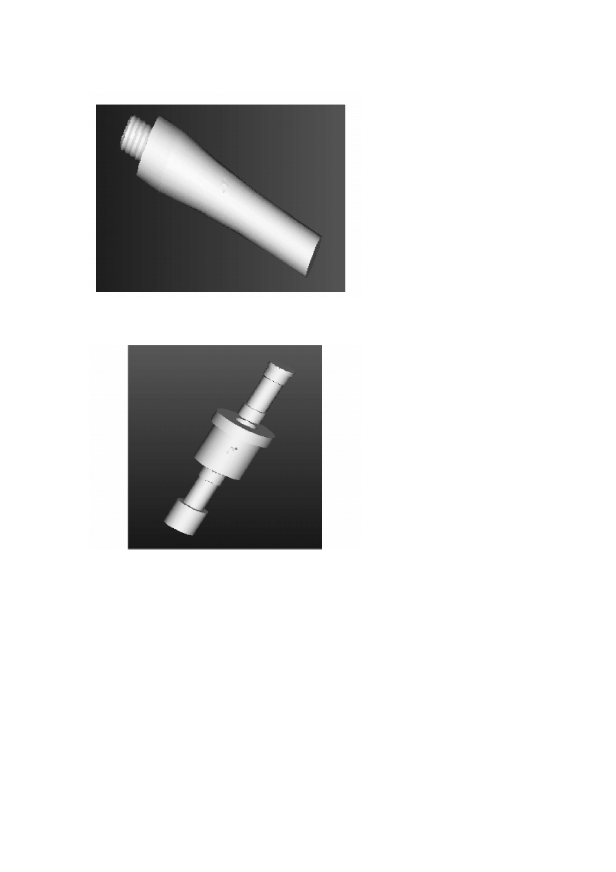
Figure 5.
Pilger Mill Mandrel.
Figure 6.
Ceramic Compaction Die Set.

678
6TH INTERNATIONAL TOOLING CONFERENCE
CRYOGENIC TREATMENT PRACTICED BY TOOL
ROOM, NFC
NFC Tool Room incorporated the cryogenic treatment along with heat
treatment cycles of various tools used for the powder (UO
2
) compaction
Komage press dies, pilger mill tools, hot extrusion dies and chisels, see Fig.
5 and 6. Other application experiments are discussed as follows.
A Powder Compaction Die Sets (Press Tools) - Tools of this type demands
high wear-resistance and strength during its service. The improvement
observed in the performance of powder compaction dies was about
three times to that of tools manufactured without cryogenic treatment.
This improvement in life of the Komage press dies is corroborating
the theoretical studies on wear resistance as explained above. The
heat treatment cycle (with cryogenic treatment) used for powder com-
paction dies is shown in the following Fig. 7.
B Pilger Mill tools - These tools are made out of AISI H11, H12 and H13.
25VMR Dies, HPTR rollers, HPTR support plates and mandrels are
the different pilger mill tools treated cryogenically. The increase in life
of the pilger mill tools is double. The heat treatment cycle followed
is shown in Table 2.
C Hot Extrusion Tools: - These tools are made out of AISI H12. Extrusion
dies are treated cryogenically. It was observed that there was no in-
crease or decrease in life of extrusion tools, after cryogenic treatment.
It was also observed that, liquid nitriding as a finishing operation
enhanced the life of extrusion tools to one and half time to that of
hardened and tempered tools. The heat treatment cycle followed for
these tools was as given in Table 3.
CRYOGENIC TEMPERATURES AND THE WAYS TO
GENERATE SUCH TEMPERATURE
The temperatures well below room temperature, i.e. 0 to –269
◦
C, are
called cryogenic temperatures. Normally these temperatures can be gener-
ated using solid carbon dioxide or mechanical refrigeration or liquefied gas
system. The solid carbon dioxide method is the oldest method and is capa-
ble of cooling components down to –80
◦
C. The mechanical refrigeration
Cryogenic treatment and it’s effect on tool steel
679
Figure 7.
Cryogenic Treatment Cycle Practiced By NFC, Tool Room.
Table 2.
Treatment for pilger mill tools
Step
Conventional
Cryogenically
1
Stress relieving at 560
◦
C
Stress relieving at 560
◦
C
2
Pre-heating at 560
◦
C
Pre- heating at 560
◦
C
3
IInd–heating at 830
◦
C
IInd –heating at 830
◦
C
4
Austenitizing at 1050
◦
C
Austenitizingat 1050
◦
C
5
Air Blast Cool to room temperature
Air Blast Cool to room temperature
6
Ist Tempering at 540
◦
C
Cryogenic Treatment
7
IInd Tempering at 540
◦
C
Tempering at 540
◦
C
8
IIIrd Tempering at 540
◦
C

680
6TH INTERNATIONAL TOOLING CONFERENCE
method may be capable of cooling to about –100
◦
Cusing freon as a convec-
tion fluid. The last and very important method in cryogenic technology is
the liquefied gas system which is capable of cooling to around –250
◦
C. The
gases that are used for generating the cryogenic temperatures are oxygen,
nitrogen, neon, hydrogen and helium. Table 4 shows boiling temperatures
of the different elements. Next, let us discuss about the liquefied gas system
using liquid nitrogen as the cooling medium.
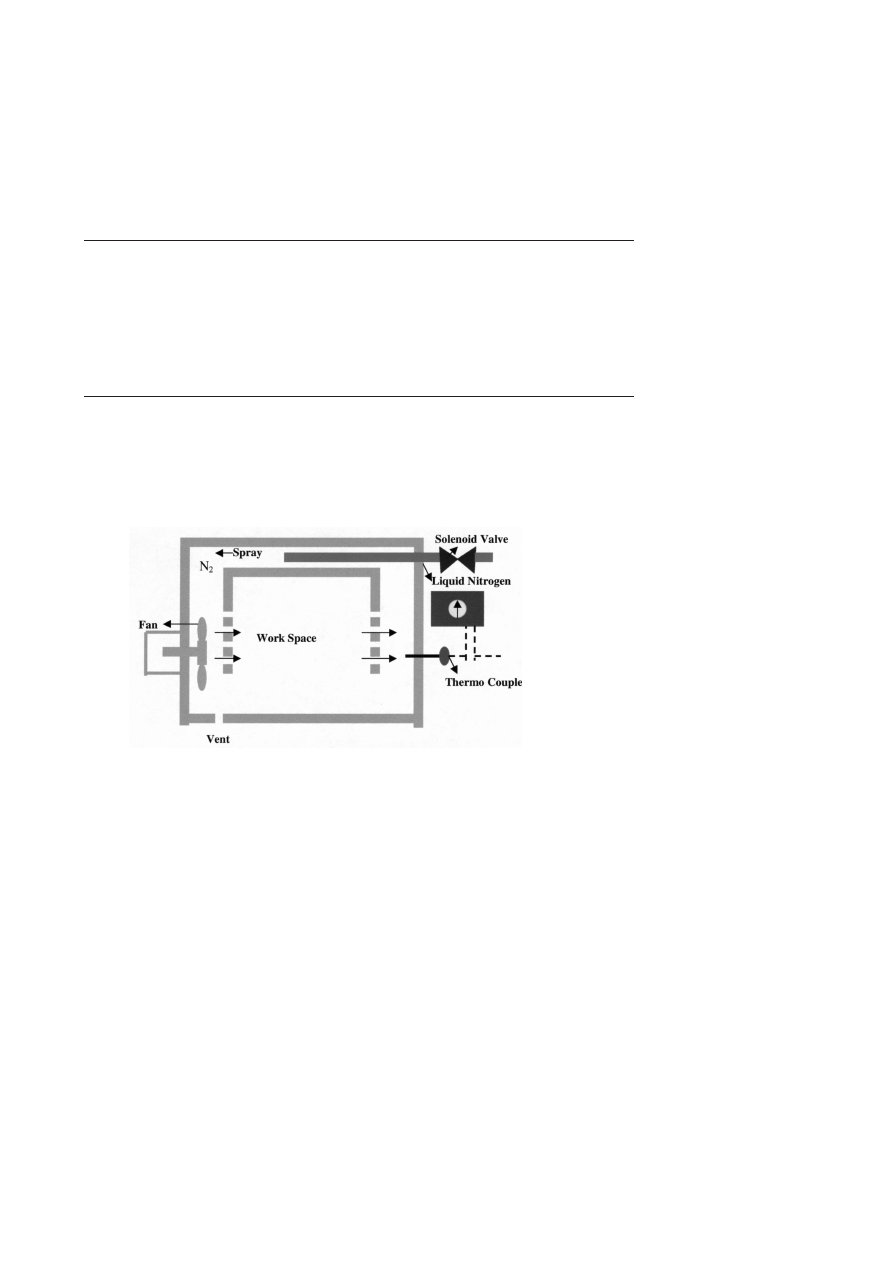
LIQUID NITROGEN SYSTEM
Components can be cooled to around –196
◦
C. The liquid nitrogen sys-
tem compared to other systems is more advantageous where it can be used
for applications with a wider temperature range. The system is capable of
cooling the components to desired temperatures at controlled rate. British
Oxygen Company originally developed this method. There are two different
techniques for utilizing liquid nitrogen in a controlled manner:
1 The Ellenite gas-cooled system, Fig. 8, which cools the components
by forced convection of cold nitrogen gas through the work-piece (–
196
◦
C).
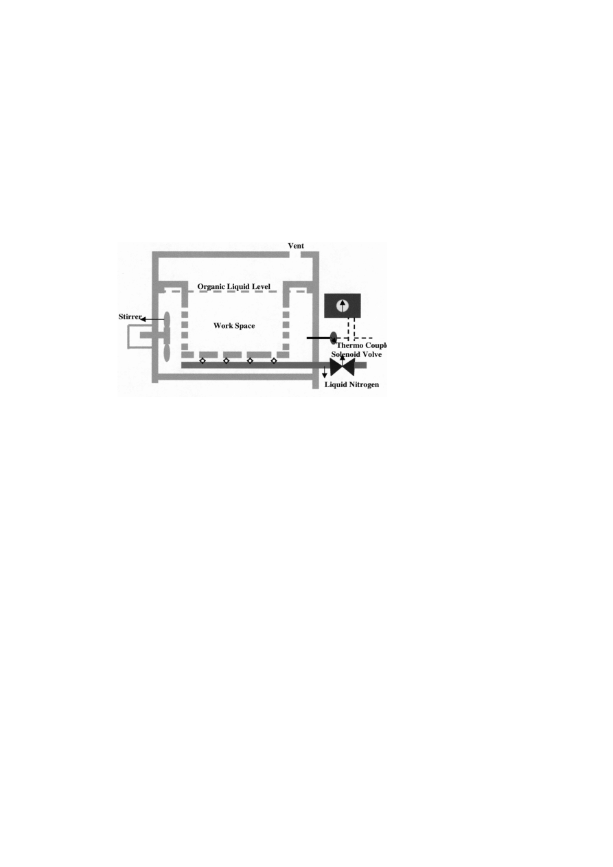
2 The Ellenite Liquid-cooled system, Fig. 9, which cools the compo-
nents indirectly by immersion in a bath of alcohol or trichloroethylene,
which is cooled by a submerged liquid nitrogen spray (–150
◦
C), tem-
perature and cooling rate controls are possible. The equipment is
relatively inexpensive compared to other systems.
CONCLUSIONS
Following inferences were recorded from our experiments in NFC tool
room:
AISI O1 & O2 (OHNS) press tools and powder compacting tools (even
with minute cross sectional areas) worked very well. The life of tools
increased.
Performance of D2 & D3 and M2 & M6 grades cutting tools and
metal forming tools were improved to 3 times to that of hardened and
tempered.
Cryogenic treatment and it’s effect on tool steel
681
Table 3.
Treatment for extrusion tools
Step
Conventional
Cryogenically
1
Stress relieving at 560
◦
C
Stress relieving at 560
◦
C
2
Pre-heating at 560
◦
C
Pre-heating at 560
◦
C
3
IInd–heating at 830
◦
C
IInd–heating at 830
◦
C
4
Austenitizing at 1050
◦
C
Austenitizing at 1050
◦
C
5
Air Blast Cool to room temperature
Air Blast Cool to room temperature
6
Ist Tempering at 610
◦
C
Cryogenic Treatment
7
IInd Tempering at 610
◦
C
Tempering at 610
◦
C
8
IIIrd Tempering at 610
◦
C
Figure 8.
Liquid Nitrogen System (Gas Cooled).

682
6TH INTERNATIONAL TOOLING CONFERENCE
Table 4.
Boiling temperature of cooling media
S No
Element
Boiling Temperature
1
Oxygen
–183
◦
C
2
Nitrogen
–196
◦
C
3
Neon
–247
◦
C
4
Hydrogen
–253
◦
C
5
Helium
–269
◦
C
6
Carbon dioxide
–80
◦
C
Performance of AISI H11, H12 and H13 grades metal forming and
pilgering tools were found to the tune of 200% to that of hardened and
tempered tools.
Chisels made out of O1 and S1 grade steel improved their performance
to 150 to 200%
Hot extrusion tooling made out of AISI H12 steel did not show any
improvement by cryogenic treatment. The reason attributed for this
phenomenon is that the working temperature of these tooling are to the
tune of 600 to 800
◦
Cwhere the microstructure transformation takes
place and hence it behaves as hardened and tempered tools. Experi-
ments conducted on hot extrusion tooling were
1 Plasma ion nitriding
2 Surface coating by detonation coating
3 Surface coating by electro spark deposition and
4 Surface hardening by liquid nitriding techniques and mirror pol-
ish.
Out of the above we found that hardening the layer by liquid nitriding fol-
lowed by mirror polishing improved the life to 150%.
It was also observed that post-cryogenic treatment fine machining (grind-
ing) is easier. Hence the cost of finishing operation comes down due to
cryogenic treatment.

Cryogenic treatment and it’s effect on tool steel
683
REFERENCES
[1] ASM Metals Handbook, Heat Treating, Vol 4, 10th ed., ASM International.
[2] Handbook of Heat Treatment of steels, page 109 and 110, by K.H.Prabhudev.
[3] Machining Source Book, ASM International.
684
6TH INTERNATIONAL TOOLING CONFERENCE
Figure 9.
Liquid Nitrogen System (Liquid Cooled).
Wyszukiwarka
Podobne podstrony:
więcej podobnych podstron