STEERING AXLE
E1.50-1.75XM (E25-35XM, E25-35XM
2
) [D114];
E2.00XMS
(E40XMS, E40XM
2
S) [D114];
E1.50-2.00XM (E25-35Z, E40ZS) [E114]
PART NO. 897881
1600 SRM 619

SAFETY PRECAUTIONS
MAINTENANCE AND REPAIR
• When lifting parts or assemblies, make sure all slings, chains, or cables are correctly
fastened, and that the load being lifted is balanced. Make sure the crane, cables, and
chains have the capacity to support the weight of the load.
• Do not lift heavy parts by hand, use a lifting mechanism.
• Wear safety glasses.
• DISCONNECT THE BATTERY CONNECTOR before doing any maintenance or repair
on electric lift trucks. Disconnect the battery ground cable on internal combustion lift
trucks.
• Always use correct blocks to prevent the unit from rolling or falling. See HOW TO PUT
THE LIFT TRUCK ON BLOCKS in the Operating Manual or the Periodic Mainte-
nance section.
• Keep the unit clean and the working area clean and orderly.
• Use the correct tools for the job.
• Keep the tools clean and in good condition.
• Always use HYSTER APPROVED parts when making repairs. Replacement parts
must meet or exceed the specifications of the original equipment manufacturer.
• Make sure all nuts, bolts, snap rings, and other fastening devices are removed before
using force to remove parts.
• Always fasten a DO NOT OPERATE tag to the controls of the unit when making repairs,
or if the unit needs repairs.
• Be sure to follow the WARNING and CAUTION notes in the instructions.
• Gasoline, Liquid Petroleum Gas (LPG), Compressed Natural Gas (CNG), and Diesel fuel
are flammable. Be sure to follow the necessary safety precautions when handling these
fuels and when working on these fuel systems.
• Batteries generate flammable gas when they are being charged. Keep fire and sparks
away from the area. Make sure the area is well ventilated.
NOTE: The following symbols and words indicate safety information in this
manual:
WARNING
Indicates a condition that can cause immediate death or injury!
CAUTION
Indicates a condition that can cause property damage!
Steering Axle
Table of Contents
TABLE OF CONTENTS
General ...............................................................................................................................................................
Description .........................................................................................................................................................
Steering Axle Assembly Repair.........................................................................................................................
Remove ...........................................................................................................................................................
Install .............................................................................................................................................................
Wheels and Hubs Repair ...................................................................................................................................
Remove and Disassemble ..............................................................................................................................
Clean ..............................................................................................................................................................
Assemble and Install .....................................................................................................................................
Spindles, Bearings, and Links Repair ..............................................................................................................
Remove and Disassemble ..............................................................................................................................
Clean ..............................................................................................................................................................
Assemble and Install .....................................................................................................................................
Steering Cylinder Repair...................................................................................................................................
Remove and Disassemble ..............................................................................................................................
Clean and Inspect ..........................................................................................................................................
Assemble and Install .....................................................................................................................................
Torque Specifications .........................................................................................................................................
Troubleshooting..................................................................................................................................................
This section is for the following models:
E1.50-1.75XM (E25-35XM, E25-35XM
2
) [D114];
E2.00XMS (E40XMS, E40XM
2
S) [D114];
E1.50-2.00XM (E25-35Z, E40ZS) [E114]
©2004 HYSTER COMPANY
i

"THE
QUALITY
KEEPERS"
HYSTER
APPROVED
PARTS
1600 SRM 619
Description
General
This section has the description and repair procedures for the steering axle assembly. See your vehicle’s SRM
for the correct Steering System, Hydraulic System, and Steering Housing and Control Unit for addi-
tional information on the steering system.
Description
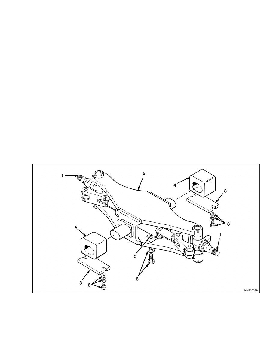
The steering axle assembly includes an axle weld-
ment, steering cylinder, and two spindle and hub as-
semblies. See Figure 1. The steering axle assem-
bly is connected to the frame by rubber mounts. The
rubber mounts permit the steering axle to move in
the lift truck frame when the lift truck travels over
rough surfaces.
The steering cylinder is held into the axle weldment
using four bolts from the bottom of the axle weld-
ment. There are O-rings, seals, and wipers in the
cylinder guides to seal the guides to the shell and
rod. The ends of the piston rod extend from both
ends of the cylinder. A single piston and seal are
at the center of the rod. Oil pressure on one side of
the piston moves the piston in the bore. The piston
pushes an equal amount of oil from the opposite side
of the cylinder.
When the piston reaches the end of the stroke, a relief
valve in the steering circuit controls the oil pressure.
The intermediate links that connect the spindle arms
to the cylinder are not adjustable.
The wheels rotate on two tapered roller bearings and
are held on the spindles by a castle nut. The wheel
bearing preload is adjusted by the castle nut. The
grease seals protect the bearings from dirt and water.
Wear sleeves protect the hub from wear by the seals.
1.
SPINDLE ASSEMBLY
2.
AXLE WELDMENT
3.
MOUNT PLATE
4.
RUBBER MOUNT
5.
STEERING CYLINDER
6.
BOLT AND WASHER
Figure 1. Steering Axle Assembly
1

Wheels and Hubs Repair
1600 SRM 619
Steering Axle Assembly Repair
REMOVE
The steering axle can be removed without removing
the counterweight. However, the counterweight can
be removed as described in the Frame 100 SRM 617.
1.
Make sure the wheels are set for straight travel.
Put the lift truck on blocks as described in your
vehicle’s Periodic Maintenance SRM. The
blocks must be high enough to let the axle, with
its wheels, to roll out from under the rear of the
lift truck.
2.
Disconnect the hydraulic lines at the steering
cylinder. Install pipe plugs in the cylinder ports
and put caps on the hydraulic lines. The pipe
plugs will prevent the spindles from turning dur-
ing removal of the axle.
3.
Slide a floor jack or the forks of another lift truck
under the steering axle. Raise the lifting device
until it holds the weight of the steering axle as-
sembly. Remove the four hex head screws and
nuts that fasten the two rubber mounts to the
lift truck. See Figure 1. Remove the two mount
plates and slowly lower the axle assembly onto
the wheels. Carefully roll the axle assembly from
under the rear of the lift truck.
INSTALL
1.
Install the rubber mounts on the axle. See Fig-
ure 1. Make sure the face of the rubber mount
with the part number is away from the axle.
Make sure the part number will be right side up
after the axle is installed.
2.
If the truck has the 14 × 4 1/4 × 8 steer tires,
install the mounts so that the thick parts are on
top. If the truck has the 15 × 5 × 11 1/4 steer tires,
install the mounts so that the thick parts are on
the bottom.
3.
Apply a lubricant, that is approved for use with
rubber, to the rubber mount. The lubricant is
used where the rubber mount fits into the frame
brackets. Make sure the lift truck is on blocks as
described in Remove.
4.
Use a floor jack or another lift truck to put the
steering axle into the position in the frame.
Make sure the rubber mounts fit inside the
frame brackets for the mounts.
5.
Install the mount plates. Tighten the four plate
bolts to 217 to 260 N•m (294 to 353 lbf ft).
6.
Remove the plugs and caps and connect the hy-
draulic lines to the steering cylinder.
7.
Operate the steering system to remove the air
from the system. Turn the steering wheel several
times from one stop to the other stop. Check for
hydraulic leaks.
Wheels and Hubs Repair
REMOVE AND DISASSEMBLE
1.
Put the lift truck on blocks as described in your
vehicle’s Periodic Maintenance SRM. The
steer wheels must just touch the floor.
2.
Remove the grease cap. See Figure 2. Remove
the cotter pin and the castle nut. Remove the
outer bearing cone.
Slide the wheel from the
spindle. Remove the inner bearing cone and the
seal from the spindle.
3.
If new wheel bearings will be installed, use a
brass drift to remove the bearing cups and the
wear sleeve.
4.
Follow this same procedure to remove the other
wheel.
CLEAN
WARNING
Cleaning solvents can be flammable and toxic
and can cause skin irritation.
When using
cleaning solvents, always follow the solvent
manufacturer’s recommended safety proce-
dures.
Clean all parts with petroleum solvent. Make sure
the bearings are clean. Make sure all solvent has
evaporated from inside the bearing cones before fill-
ing them with grease.
2
1600 SRM 619
Wheels and Hubs Repair
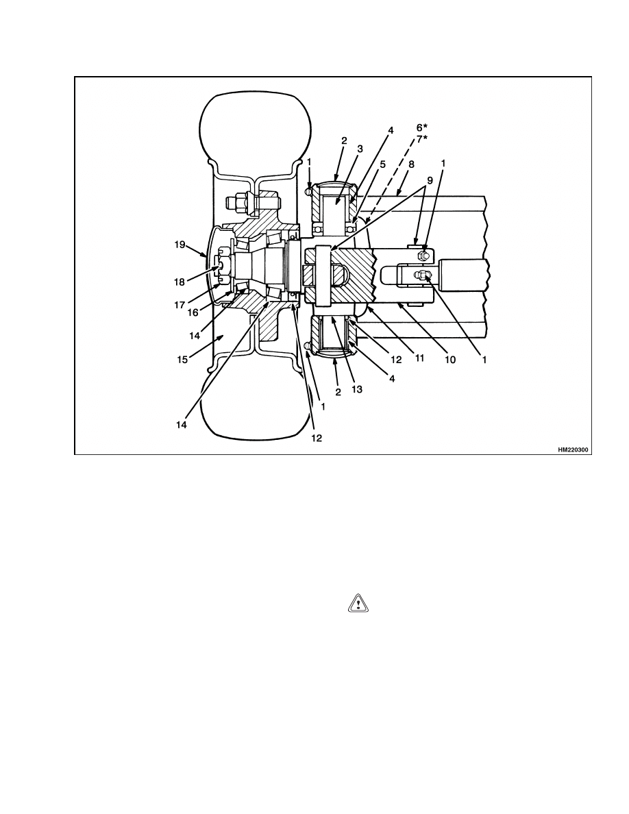
1.
LUBE FITTING
2.
EXPANSION PLUG
3.
KINGPIN
4.
NEEDLE BEARING
5.
THRUST BEARING
6.
LOCK NUT
7.
SETSCREW
8.
AXLE WELDMENT
9.
LINK PIN
10. INTERMEDIATE LINK
11. SPINDLE
12. OIL SEAL
13. SHIMS
14. ROLLER BEARING
15. WHEEL ASSEMBLY
16. WASHER
17. CASTLE NUT
18. COTTER PIN
19. HUB CAP
*ON OPPOSITE SIDE OF SPINDLE. SEE FIGURE 3.
Figure 2. Spindle and Link Assembly
ASSEMBLE AND INSTALL
1.
If new wheel bearings will be installed, use a
press to install the new bearing cups in the
wheel.
See Figure 2.
Install the grease seal
on the spindle. Fill the bearing cones with the
wheel bearing grease specified in your vehicle’s
Periodic Maintenance SRM. Make sure the
bearings are completely filled with grease. In-
stall the inner bearing cone on the spindle.
CAUTION
Do not damage the seals during installation.
2.
Carefully slide the wheel onto the spindle with-
out damaging seals. Install the outer bearing
cone.
NOTE: For older model E1.50-2.00XM (E25-35XM,
E40XMS) (D114) lift trucks, go to Step 3. For newer
model E1.50-2.00XM (E25-35XM
2
and E40XM
2
S)
(D114), and E1.50-2.00XM (E25-35Z, E40ZS) (E114)
lift trucks, go to Step 4.
3
Spindles, Bearings, and Links Repair
1600 SRM 619
3.
Install the castle nut. Tighten the castle nut to
200 N•m (150 lbf ft) while the wheel is rotated.
Loosen the castle nut until the wheel turns freely.
Tighten the castle nut to 34 N•m (25 lbf ft). In-
stall the cotter pin at the nearest alignment po-
sition. Install the hub cap.
4.
Install the castle nut. Tighten the castle nut to
68 N•m (50 lbf ft), while rotating the hub in both
directions to properly set bearings. Loosen nut
by 1/4 turn. Tighten nut to 3 N•m (27 lbf in).
Pull on the wheel axially to ensure that there
is no end play (movement). If there is end play,
repeat Step 1 and Step 2. Adjust castle nut left or
right to closest spindle hole alignment position.
Lock nut in place with cotter pin. If cotter pin
cannot be installed, tighten the castle nut 3 N•m
(27 lbf in) until the cotter pin can be installed.
5.
Follow this same procedure to assemble and in-
stall the other wheel.
Spindles, Bearings, and Links Repair
REMOVE AND DISASSEMBLE
1.
Remove two lock nuts, two setscrews, two link
pins, and the intermediate link. See Figure 2,
Figure 3, and Figure 4.
2.
Remove the upper and lower expansion plugs,
lock nut, setscrew, king pin, spindle, thrust bear-
ing, shims, and the oil seal. Discard the oil seal.
3.
Remove damaged lubrication fittings. Make a
note of the direction of the 90 fittings.
4.
Using a press, remove the upper and lower nee-
dle bearings from the axle weldment.
5.
Do Step 1 through Step 4 to remove and disas-
semble the other spindle, bearings, and links.
6.
If the link bushings in the spindles are loose on
the pins or in the bores, remove the bushings
from the spindles and discard.
CLEAN
WARNING
Cleaning solvents can be flammable and toxic
and can cause skin irritation.
When using
cleaning solvents, always follow the solvent
manufacturer’s recommended safety proce-
dures.
Clean all parts with petroleum solvent. Make sure
the bearings are clean. Make sure all solvent has
evaporated from inside the bearing cones before fill-
ing them with grease.
ASSEMBLE AND INSTALL
NOTE: Perform Step 1 through Step 3 only if the nee-
dle bearings, bushing, and/or the lubrication fittings
were removed.
1.
If removed, install a new bushing into the spin-
dle. Make sure the lubrication hole in the bush-
ing is aligned with the lubrication fitting hole in
the spindle.
2.
Lubricate new needle bearings with the wheel
bearing grease specified in your vehicle’s Pe-
riodic Maintenance SRM. Install the needle
bearings into the axle weldment using a press.
Make sure the lubrication holes in the bearing
races are aligned with the lubrication fitting
holes in the axle weldment.
3.
Install new lubrication fittings as necessary.
Make sure the 90 fittings are pointing in the
same direction as removed for access during
lubrication.
4.
Coat the new oil seal with grease, and install it
into the axle weldment with the lip of the oil seal
facing up.
5.
Lubricate the thrust bearing with the wheel
bearing grease specified in your vehicle’s Pe-
riodic Maintenance SRM. Install the spindle
and thrust bearing into the axle weldment.
6.
Lift the spindle and thrust bearing combination
as high as possible so that all the clearance is at
the bottom. Using a feeler gauge, measure the
distance between the bottom of the spindle and
the oil seal. Subtract 0.2 mm (0.008 in.) from
the measured dimension to find the shim pack
thickness.
4
1600 SRM 619
Spindles, Bearings, and Links Repair
1.
AXLE WELDMENT
2.
LINK PIN
3.
CYLINDER
4.
SETSCREW
5.
LOCK NUT
6.
LUBE FITTING
7.
INTERMEDIATE LINK
8.
NEEDLE BEARING
9.
KING PIN
10. OIL SEAL
11. EXPANSION PLUG
12. SHIMS
13. BUSHING
14. SPINDLE
15. THRUST BEARING
Figure 3. Spindle Assembly (E1.50-2.00XM)
CAUTION
The shims used in Step 7 are very thin and
are easily bent. Use care when installing the
shims and the kingpin to prevent damage to
the shims.
7.
Install the shim pack, of Step 6, between the bot-
tom of the spindle and the axle weldment.
NOTE: Do Step 3 and Step 4 only if the bearings are
worn or the lubrication fittings are damaged.
NOTE: It can be necessary to use a tapered drift to
align the holes in the axle weldment, spindle, bear-
ings, and shims.
8.
Carefully install the kingpin into the axle weld-
ment with the indent facing the setscrew hole in
the spindle.
5
Steering Cylinder Repair
1600 SRM 619
1.
PIN
2.
BEARING
3.
O-RING
4.
OIL SEAL
5.
LINK
6.
SPINDLE
7.
BUSHING
8.
SCREW
9.
NUT
10. LUBE FITTING
11. SLEEVE (UPPER)
Figure 4. Spindle Assembly (E25-35XM,
E25-35XM
2
, E40XMS, and E40XM
2
S)
9.
Install the setscrew into the spindle and kingpin.
Install the lock nut to lock the setscrew.
10. Install a new oil seal and new upper and lower
expansion plugs into the axle weldment. Use a
punch at three equal points on each expansion
plug to seal the plugs into the bores.
NOTE: If the steering cylinder is not installed on the
axle weldment, install the cylinder before installing
the link pins.
11. Install the intermediate link onto the steering
cylinder and the spindle.
12. Install the link pins to fasten the intermediate
link to the cylinder and spindle. Make sure the
indents of the link pins are facing the setscrew
holes in the intermediate link.
13. Install the setscrews to fasten the link pins.
Then, tighten the lock nuts.
14. Follow this same procedure to assemble and in-
stall the other spindle, bearings and intermedi-
ate link.
Steering Cylinder Repair
REMOVE AND DISASSEMBLE
1.
Disconnect the hydraulic lines at the steering
cylinder. Install caps on the cylinder fittings and
the hydraulic lines.
2.
Remove the capscrews and washers that fasten
the cylinder to the axle weldment. Remove the
steering cylinder from the axle weldment.
3.
Hold one port of the steering cylinder over a con-
tainer. Remove the caps from the hydraulic fit-
tings of the cylinder. Push the rod toward the
end of the shell that is over the container. Oil will
drain from the cylinder. Carefully put the other
port over the container and repeat this procedure
to drain all of the oil from the cylinder.
4.
Carefully remove one guide from the shell and
rod. Keep the cylinder rod aligned in the center of
the shell during removal so that the parts are not
damaged. Carefully pull the cylinder rod and pis-
ton from the shell. Remove the other guide from
the shell. Remove and discard all snap rings,
seals, wipers, and O-rings. See Figure 5.
6
1600 SRM 619
Steering Cylinder Repair
5.
If the link bushings in the cylinder rod are loose
on the pins or in the bores, remove the bushings
from the cylinder rod and discard.
NOTE: Make a note of the direction of the 90 hy-
draulic fittings on the cylinder for correct installa-
tion.
CLEAN AND INSPECT
WARNING
Cleaning solvents can be flammable and toxic
and can cause skin irritation.
When using
cleaning solvents, always follow the solvent
manufacturer’s recommended safety proce-
dures.
1.
Clean all parts in petroleum solvent.
2.
Inspect the piston rod for grooves or damage. Re-
move small scratches with fine emery cloth. In-
spect the cylinder bore for damage. Inspect the
mounts for cracks.
1.
SNAP RING
2.
DUST SEAL
3.
U-PACKING
4.
GUIDE
5.
BUSHING
6.
O-RING
7.
BACKUP RING
8.
ROD
9.
SEAL
10. SHELL
Figure 5. Steering Cylinder
7

Torque Specifications
1600 SRM 619
ASSEMBLE AND INSTALL
1.
If removed, install a new bushing into the cylin-
der rod. Make sure the lubrication hole in each
bushing is aligned with the lubrication fitting
hole in the cylinder rod.
2.
Put new O-rings, seals, and wipers in warm
hydraulic oil. Install the new O-rings, backup
rings, seals, wipers, and snap rings as shown in
Figure 5.
3.
Keep the cylinder rod aligned in the center of the
shell during installation so that the parts are not
damaged. Carefully slide the cylinder rod and
piston into the shell. Install the guides into the
shell and tighten to 102.7 to 132.7 N•m (75.8 to
97.9 lbf ft).
4.
Install the cylinder on the axle weldment using
the bolts, washers, and nuts.
Make sure the
ports or hydraulic fittings are on the front (mast)
side of the axle weldment. Tighten the mount
nuts to 41 to 49 N•m (30 to 36 lbf ft).
5.
Install the intermediate link, link pins, all
setscrews, and all lock nuts. Tighten the lock
nuts.
6.
If the 90 hydraulic fittings and lock nuts were re-
moved from the cylinder, they must be installed
as removed. The fittings must be in a direction
to allow correct alignment of the hydraulic hoses.
Use new O-rings and tighten the lock nuts after
there is correct alignment.
7.
Remove the caps and connect the hydraulic lines
to the steering cylinder. Operate the steering
system to remove the air from the steering sys-
tem. Turn the steering wheel several times from
one stop to the other. Check for hydraulic leaks.
Torque Specifications
Steering Axle Mounting Bolts
41 to 49 N•m (30 to 36 lbf ft)
Castle Nut (Initial) For older model E1.50-2.00XM
(E25-35XM, E40XMS) (D114) lift trucks, use
the torque values given below.
200 N•m (148 lbf ft)
Castle Nut (Final)
34 N•m (25 lbf ft)
Castle Nut (Initial) For newer model
E1.50-2.00XM (E25-35XM
2
and E40XM
2
S) (D114),
and E1.50-2.00XM (E25-35Z, E40ZS) (E114) lift
trucks, use the torque values given below.
68 N•m (50 lbf ft)
Castle Nut (Final)
3 N•m (25 lbf in)
Spindle Lock Nut (Initial)
81 to 98 N•m (60 to 72 lbf ft)
Steering Cylinder Mounting Bolts
294 to 353 N•m (217 to 260 lbf ft)
8

1600 SRM 619
Troubleshooting
Troubleshooting
PROBLEM
POSSIBLE CAUSE
PROCEDURE OR ACTION
The steer wheels do not move
when the steering wheel is
turned.
The oil level is low or there is no oil
in the tank.
Fill tank. Check for leaks.
The steering control unit is dam-
aged.
Repair or install new control unit.
No oil flows from the steering control
unit to the steering cylinder.
Repair or install new components.
Check for leaks.
Slow or difficult steering.
Relief valve for the steering system
needs adjustment.
Adjust or install new relief valve.
Low oil pressure from the hydraulic
pump.
Check for restrictions.
See Trou-
bleshooting Chart in section Hy-
draulic System 1900 SRM 559.
Seal in the steering cylinder has a
leak.
Install new seal.
Steering control unit is worn or has
damage.
Repair or install new control unit.
Steering wheel turns the
tires in the wrong direction.
The hydraulic lines are not con-
nected correctly at the steering
cylinder or at the steering control
unit.
Connect lines properly. Remove air
from system.
Steering
function
contin-
ues after the steering wheel
stops.
The steering control unit was assem-
bled wrong or has damage.
Repair or install new control unit.
There is air in the steering
system.
The oil level in the tank is low.
Add
hydraulic
oil
as
necessary.
Check for leaks.
Air was not removed after repair to
the hydraulic or steering system.
Remove air from system.
The hydraulic pump has an air leak
at the inlet.
Repair system. Remove air from sys-
tem.
9

NOTES
____________________________________________________________
____________________________________________________________
____________________________________________________________
____________________________________________________________
____________________________________________________________
____________________________________________________________
____________________________________________________________
____________________________________________________________
____________________________________________________________
____________________________________________________________
____________________________________________________________
____________________________________________________________
____________________________________________________________
____________________________________________________________
____________________________________________________________
____________________________________________________________
____________________________________________________________
____________________________________________________________
____________________________________________________________
____________________________________________________________
10


TECHNICAL PUBLICATIONS
1600 SRM 619
6/04 (12/03)(5/96) Printed in United Kingdom
Document Outline
- toc
Wyszukiwarka
Podobne podstrony:
więcej podobnych podstron