METRIC AND INCH
(SAE) FASTENERS
ALL MODELS
PART NO. 910442
8000 SRM 231

SAFETY PRECAUTIONS
MAINTENANCE AND REPAIR
• When lifting parts or assemblies, make sure all slings, chains, or cables are correctly
fastened, and that the load being lifted is balanced. Make sure the crane, cables, and
chains have the capacity to support the weight of the load.
• Do not lift heavy parts by hand, use a lifting mechanism.
• Wear safety glasses.
• DISCONNECT THE BATTERY CONNECTOR before doing any maintenance or repair
on electric lift trucks. Disconnect the battery ground cable on internal combustion lift
trucks.
• Always use correct blocks to prevent the unit from rolling or falling. See HOW TO PUT
THE LIFT TRUCK ON BLOCKS in the Operating Manual or the Periodic Mainte-
nance section.
• Keep the unit clean and the working area clean and orderly.
• Use the correct tools for the job.
• Keep the tools clean and in good condition.
• Always use HYSTER APPROVED parts when making repairs. Replacement parts
must meet or exceed the specifications of the original equipment manufacturer.
• Make sure all nuts, bolts, snap rings, and other fastening devices are removed before
using force to remove parts.
• Always fasten a DO NOT OPERATE tag to the controls of the unit when making repairs,
or if the unit needs repairs.
• Be sure to follow the WARNING and CAUTION notes in the instructions.
• Gasoline, Liquid Petroleum Gas (LPG), Compressed Natural Gas (CNG), and Diesel fuel
are flammable. Be sure to follow the necessary safety precautions when handling these
fuels and when working on these fuel systems.
• Batteries generate flammable gas when they are being charged. Keep fire and sparks
away from the area. Make sure the area is well ventilated.
NOTE: The following symbols and words indicate safety information in this
manual:
WARNING
Indicates a condition that can cause immediate death or injury!
CAUTION
Indicates a condition that can cause property damage!

Metric and Inch (SAE) Fasteners
Table of Contents
TABLE OF CONTENTS
General ...............................................................................................................................................................
Threaded Fasteners.......................................................................................................................................
Nomenclature, Threads.................................................................................................................................
Strength Identification ..................................................................................................................................
Cotter (Split) Pins..........................................................................................................................................
Fastener Torque Tables .................................................................................................................................
Conversion Table ...........................................................................................................................................
This section is for the following models:
All Models
©2005 HYSTER COMPANY
i

"THE
QUALITY
KEEPERS"
HYSTER
APPROVED
PARTS
8000 SRM 231
General
General
THREADED FASTENERS
Threaded fasteners, like bolts, nuts, capscrews, and
studs, are made to specifications that describe the
mechanical strength and hardness of the fastener.
A fastener used in a design application is selected
according to its specifications.
Hyster
®
Company
buys parts from many countries.
Parts that are
purchased must be to Hyster
®
Company standards.
There are several standards used by these countries
in the manufacture of threaded fasteners. Many of
these fasteners are similar, but cannot be used as a
direct replacement. To make sure that you have the
correct fastener, order fasteners and parts through
the Hyster
®
Parts Depot.
Service persons must use replacement fasteners
that have the same specifications. Fasteners made
to each specification have identification marks for
that specification.
This specification is commonly
called "Grade" for SAE standards and "property
class" for metric standards. This section describes
the identification of some common fasteners.
The metric system used by Hyster
®
Company is
described as SI (Le Systeme d’Unites or the In-
ternational System of units, also called SI in all
languages). The SI System of measurement is de-
scribed in ISO Standard 1000, 1973. A conversion
table of common measurements is shown in Table 7.
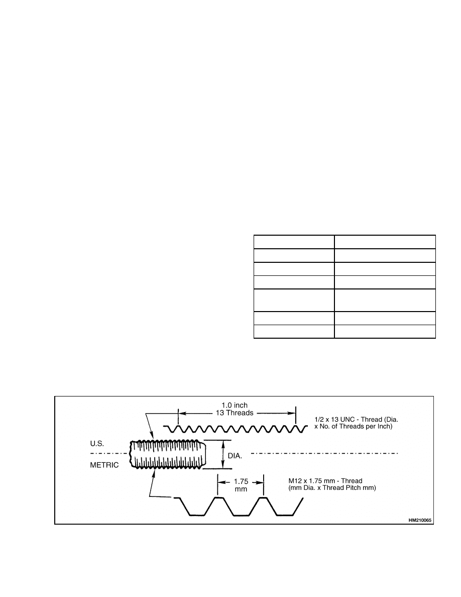
NOMENCLATURE, THREADS
The thread design is specified by a series of numbers
and letters for inch and metric fasteners. See Fig-
ure 1. The diameter of the shank of the fastener is
shown first in the series [M12 = 12 mm, M20 = 20
mm (1/2 = 1/2 in., 3/4 = 3/4 in.)].
The number of threads per inch is normally not
shown for inch nomenclature and only the UNC
(Unified National Coarse) or UNF (Unified National
Fine) is shown. This number of threads per inch is
not shown because a UNC or UNF fastener has a
standard number of threads per inch for a specific
diameter.
Metric fasteners show the number of
threads per millimeter.
The length of the shank is often indicated as part of
the description of a fastener. This length is shown
in inches for inch fasteners and in millimeters for
metric fasteners.
A capscrew will have the following description:
Metric
Inch
M12 × 1.75 × 50
1/2 × 13 UNC × 1-1/2
A B C
A B C D
A = Thread Size
A = Shank Diameter
B = Pitch
B = Number of Threads
Per Unit of Length
C = Length
C = type of Thread
D = Shank Length
Figure 1. Thread Design
1
General
8000 SRM 231
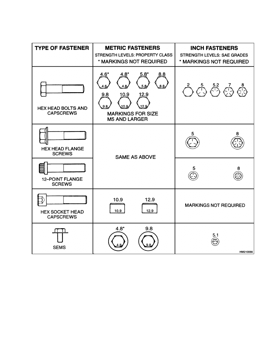
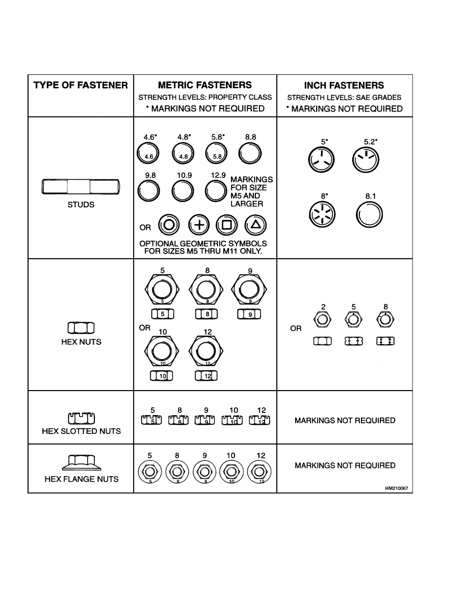
STRENGTH IDENTIFICATION
CAUTION
When fasteners must be replaced, the new fas-
teners must be of the same strength or greater
than the original fasteners. The new fasteners
must also be the correct size.
NOTE: Identification marks are according to bolt
strength. The higher the number or the increase
in the number of marks indicates increased bolt
strength.
The most common property classes for metric fasten-
ers are 8.8 and 10.9. The property class is marked
with a number on the head of the capscrew or on
a nut. Property classes less than 8.8 are often not
marked. Grades for inch bolts go from 2 to 8. Grade
2 fasteners normally do not have any marks. The
following tables show the marks that identify the
grades and property classes for different fasteners.
COTTER (SPLIT) PINS
Cotter (split) pins are used in many applications on
your forklift. They are typically used to retain parts
such as pins and nuts. Cotter (split) pins are typi-
cally not used as load-bearing members. Service per-
sonnel must use new cotter (split) pins. Do not reuse
a cotter (split) pin. Replacement cotter (split) pin
must be of the correct size. See Table 8.
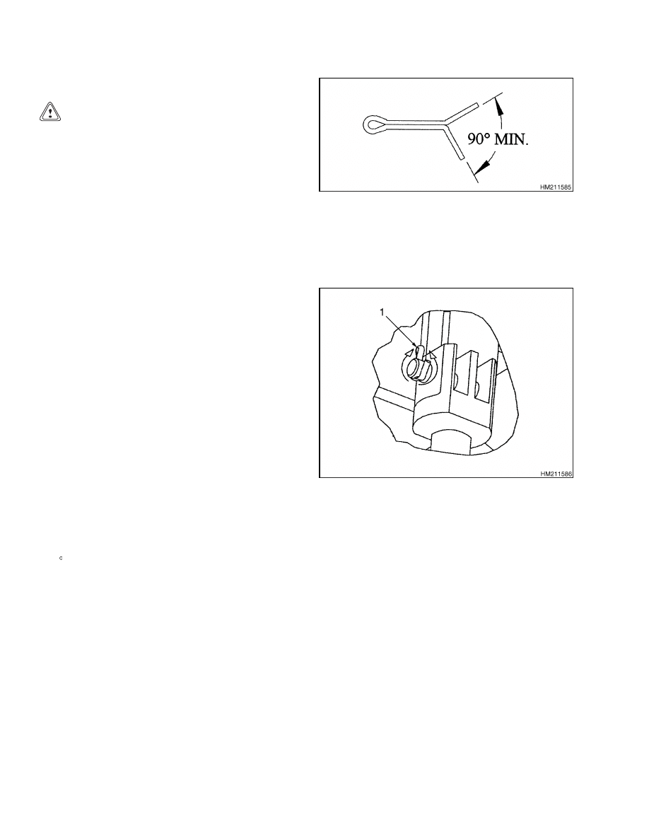
The legs of a cotter (split) pin are bent for the follow-
ing reasons:
• To retain the cotter (split) pin in the part
• To provide clearance between the cotter pin legs
and other parts or members. One or both cotter
(split) pin legs must be bent to provide a minimum
90 angle between the legs. See Figure 2.
Figure 2. Minimum Angle Between Cotter Pin
Legs
Unless otherwise specified, the legs of chain anchor
cotter (split) pins are to be bent against the pin. See
Figure 3.
1.
COTTER PIN
Figure 3. Cotter (Split) Pins Used On Mast
Chain Anchors
2
8000 SRM 231
General
Table 1. Bolts and Screws
3
General
8000 SRM 231
Table 2. Studs and Nuts
4
8000 SRM 231
General
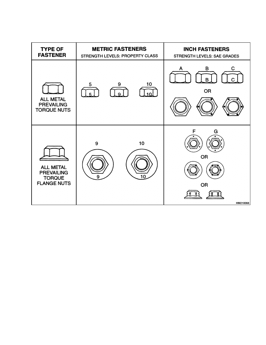
Table 3. Torque Nuts
5
General
8000 SRM 231
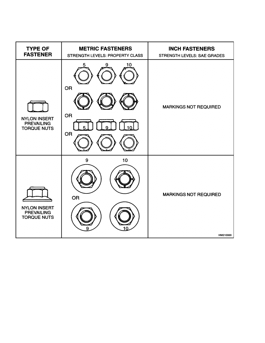
Table 4. Torque Nuts With Nylon Insert
6

8000 SRM 231
General
FASTENER TORQUE TABLES
Table 5. Torque Values for Metric Fasteners*
Property Class
5.8
1
Grade
8.8
2
Grade
10.9
3
Size and Pitch
N•m
lbf ft
N•m
lbf ft
N•m
lbf ft
M3 × 0.5
M3.5 × 0.6
M4 × 0.7
M5 × 0.8
M6 × 1
0.62
0.97
1.44
2.91
4.94
0.5
0.7
1.1
2.1
3.6
0.99
1.55
2.30
4.65
7.90
0.7
1.1
2.1
3.6
6
1.34
2.11
3.13
6.33
10.8
1.0
1.6
2.3
4.7
8
M8 × 1.25
M8 × 1
M10 × 1.5
M10 × 1.25
12.0
12.8
23.8
25.1
9
9
18
19
19.2
20.5
38.0
40.1
14
15
28
30
26.1
27.9
52
55
19
21
38
41
M12 × 1.75
M12 × 1.25
M14 × 2
M14 × 1.5
41.4
45.3
66
72
31
33
49
53
66
72
105
115
49
53
77
85
90
98
145
155
66
72
105
115
M16 × 2
M16 × 1.5
M20 × 2.5
M20 × 1.5
105
110
200
225
77
81
150
165
165
175
320
355
122
130
235
260
225
240
435
485
165
175
320
360
M24 × 3
M24 × 2
M27 × 3
M27 × 2
345
375
505
550
255
275
370
405
555
605
810
875
410
445
600
645
755
820
1,100
1,190
560
605
810
880
M30 × 3.5
M30 × 3
M30 × 2
M33 × 3.5
M33 × 2
690
715
765
940
1,030
510
530
565
695
760
1,100
1,140
1,220
1,500
1,640
810
840
900
1,100
1,210
1,500
1,550
1,660
2,040
2,240
1,100
1,140
1,230
1,510
1,660
M36 × 4
M36 × 3
M39 × 4
M39 × 3
1,200
1,280
1,560
1,640
885
945
1,150
1,210
1,930
2,040
2,490
2,630
1,430
1,510
1,840
1,940
2,620
2,780
3,390
3,570
1,940
2,050
2,500
2,640
M42 × 4.5
M42 × 3
M45 × 4.5
M45 × 3
M48 × 5
M48 × 3
1,930
2,070
2,410
2,580
2,900
3,160
1,430
1,530
1,780
1,910
2,140
2,330
3,080
3,320
3,850
4,120
4,630
5,040
2,280
2,450
2,840
3,040
3,420
3,720
4,200
4,510
5,240
5,610
6,300
6,860
3,100
3,330
3,870
4,140
4,650
5,060
* Unless otherwise specified
1
Approximately equal to Grade 2
2
Approximately equal to Grade 5
3
Approximately equal to Grade 8
7

General
8000 SRM 231
Table 6. Torque Values for Inch Fasteners*
Grade
2
1
Grade
5
2
Grade
8
3
Size and Pitch
lbf ft
N•m
lbf ft
N•m
lbf ft
N•m
1/4
1/4
20 UNC
28 UNF
4
5
6
6
6
7
9
10
9
10
12
14
5/16
5/16
18 UNC
24 UNF
8
9
11
13
13
14
18
20
18
20
25
28
3/8
3/8
16 UNC
24 UNF
15
17
20
23
23
26
31
36
33
37
44
50
7/16
7/16
14 UNC
20 UNF
24
27
33
36
37
41
50
56
52
58
71
79
1/2
1/2
13 UNC
20 UNF
37
41
50
56
57
64
77
86
80
90
110
120
9/16
9/16
12 UNC
18 UNF
53
59
72
80
82
91
110
125
115
130
155
175
5/8
5/8
11 UNC
18 UNF
73
83
99
110
115
130
155
175
160
180
215
245
3/4
3/4
10 UNC
16 UNF
130
145
175
195
200
225
270
300
280
315
380
425
7/8
7/8
9 UNC
14 UNF
125
140
170
185
320
355
435
480
455
500
615
680
1
1
8 UNC
14 UNF
185
210
255
285
485
540
655
735
680
765
925
1,040
1-1/8
1-1/8
7 UNC
12 UNF
265
300
360
405
595
670
805
905
965
1,080
1,310
1,470
1-1/4
1-1/4
7 UNC
12 UNF
375
415
510
565
840
930
1,140
1,260
1,360
1,500
1,850
2,050
1-3/8
1-3/8
6 UNC
12 UNF
490
560
665
760
1,100
1,250
1,490
1,700
1,780
2,040
2,420
2,760
1-1/2
1-1/2
6 UNC
12 UNF
650
735
885
995
1,460
1,650
1,980
2,230
2,370
2,670
3,210
3,620
* Unless otherwise specified
1
Approximately equal to metric Property Class 5.8
2
Approximately equal to metric Property Class 8.8
3
Approximately equal to metric Property Class 10.9
8
8000 SRM 231
General
CONVERSION TABLE
Table 7. Conversion Table for Metric and English Units
Multiply
By
To Get
Multiply
By
To Get
Area
inches
2
(in.
2
)
× 6.452
= centimeters
2
(cm
2
)
centimeters
2
(cm
2
)
× 0.155
= inches
2
(in.
2
)
feet
2
(ft
2
)
× 0.093
= meters
2
(m
2
)
meters
2
(m
2
)
× 10.764 = feet
2
(ft
2
)
Linear
inches (in.)
× 25.4
= millimeters (mm)
millimeter (mm)
× 0.039
= inches (in.)
feet (ft)
× 0.305
= meters (m)
meter (m)
× 3.281
= feet (ft)
yards (yd)
× 0.914
= meters (m)
meter (m)
× 1.094
= yards (yd)
miles (mi)
× 1.609
= kilometers (km)
kilometer (km)
× 0.621
= miles (mi)
Mass
ounces (oz)
× 28.35
= grams (g)
grams (g)
× 0.035
= ounces (oz)
pounds (lb)
× 0.454
= kilograms (kg)
kilograms (kg)
× 2.205
= pounds (lb)
tons (2,000 lb)
× 907.18
= kilograms (kg)
kilograms (kg)
× 0.001
= tons (2,000 lb)
tons (2,000 lb)
× 0.907
= metric ton (t)
metric ton (t)
× 1.102
= tons (2,000 lb)
Power
horsepower (hp)
× 0.746
= kilowatts (kW)
kilowatts (kW)
× 1.34
= horsepower (hp)
Pressure
pounds/in.
2
(psi)
× 6.895
= kilopascal (kPa)
kilopascals (kPa)
× 0.145
= pounds/in.
2
(psi)
pounds/in.
2
(psi)
× 0.007
= megapascal (MPa)
megapascals (MPa)
× 145.04 = pounds/in.
2
(psi)
Temperature
( Fahrenheit 32)
× 0.56
= Celsius (C)
( Celsius × 1.8) +32
= Fahrenheit
Torque
pound inches (lbf in.)
× 0.113
= Newton meter (N•m)
Newton meter (N•m)
× 8.851
= pound inches (lb
f
in.)
pound feet (lbf ft)
× 1.356
= Newton meter (N•m)
Newton meter (N•m)
× 0.738
= pound feet (lb
f
ft)
Velocity
miles/hour (mph)
× 1.609
= kilometer/hour (km/h) kilometer/hr (km/h)
× 0.621
= miles/hour (mph)
Volume
inches
3
(in.
3
)
× 16.387
= centimeters
3
(cm
3
)
centimeters
3
(cm
3
)
× 0.061
= inches
3
(in.
3
)
inches
3
(in.
3
)
× 0.016
= liters (l)
liters (l)
× 61.024 = inches
3
(in.
3
)
quarts, U.S. (qt)
× 0.946
= liters (l)
liters (l)
× 1.057
= quarts, U.S. (qt)
quarts, U.S. (qt)
× 0.83
= quarts, Imp. (qt)
quarts, Imp. (qt)
× 1.205
= quarts, U.S. (qt)
gallons, U.S. (gal)
× 3.785
= liters (l)
liters (l)
× 0.264
= gallons, U.S. (gal)
gallons, U.S. (gal)
× 0.83
= gallons, Imp. (gal)
gallons, Imp. (gal)
× 1.205
= gallons, U.S. (gal)
ounces (oz)
× 29.57
= milliliters (ml)
milliliters (ml)
× 0.034
= ounces (oz)
9
General
8000 SRM 231
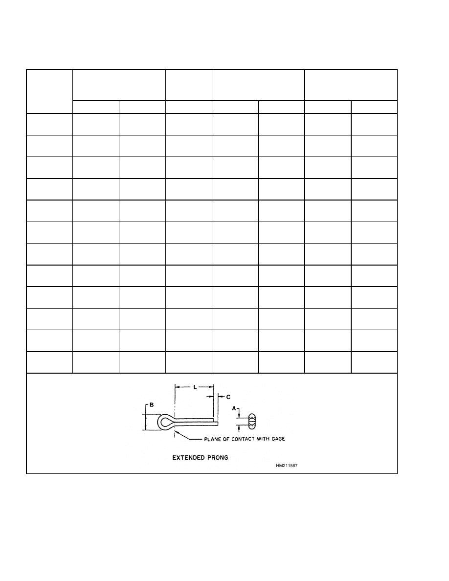
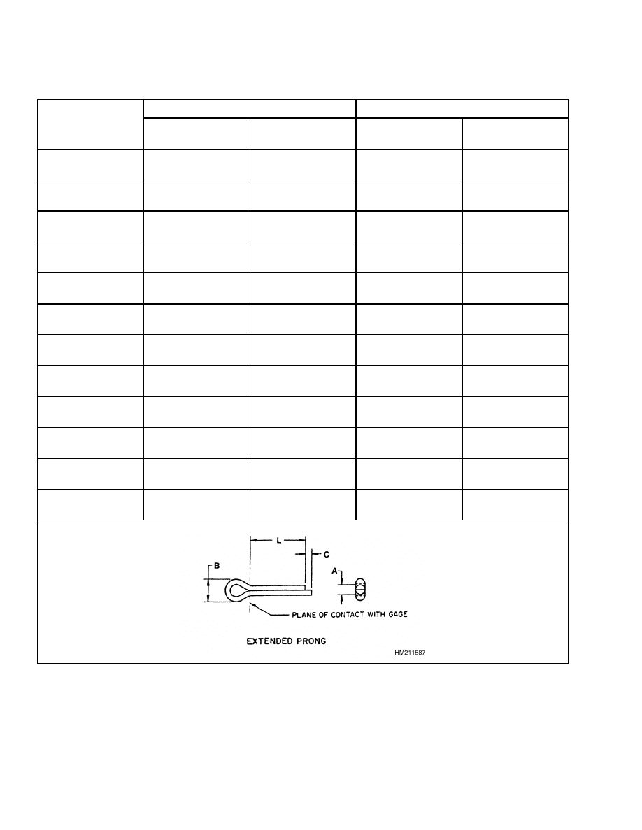
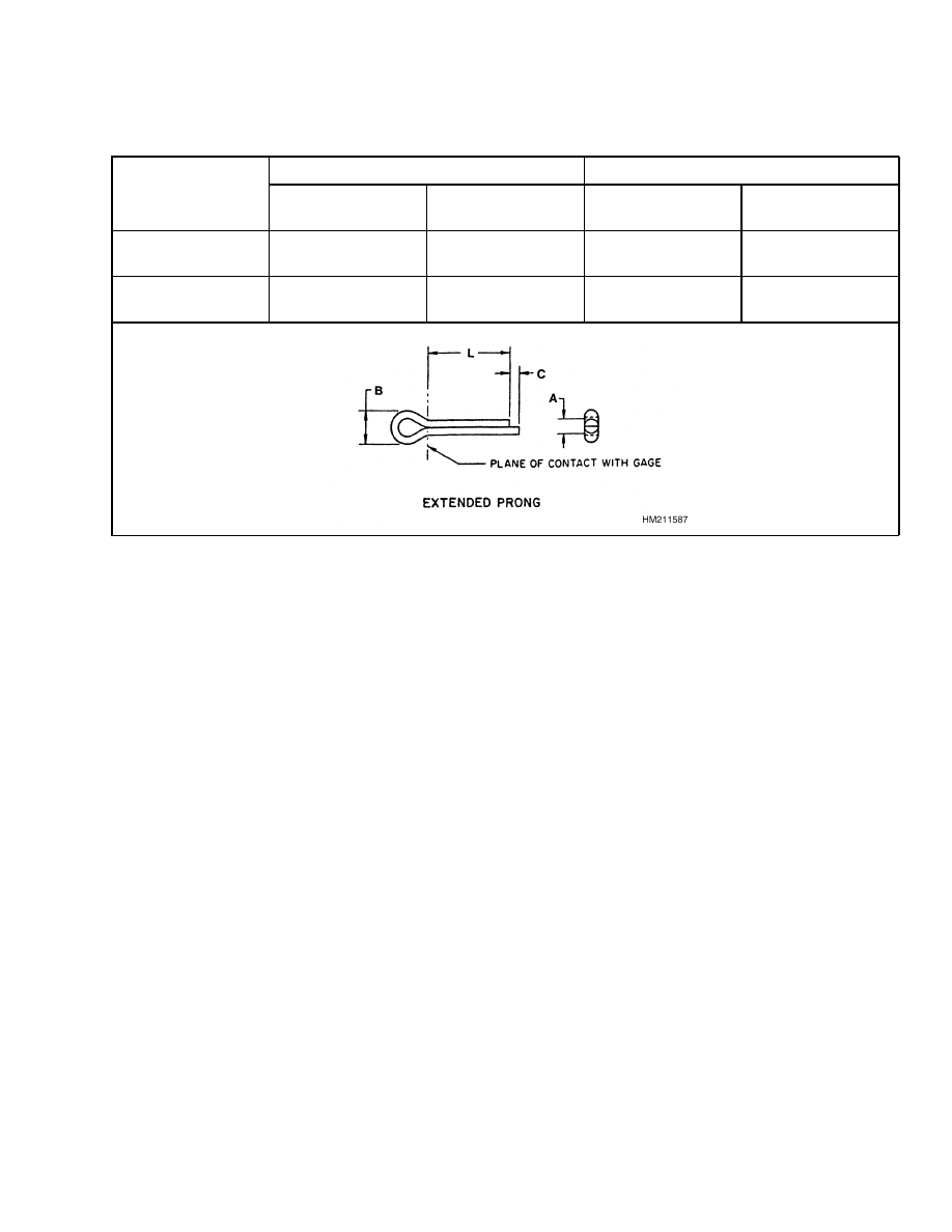
Table 8. Cotter Pin Dimensional Data
Shank Diameter
A
Head Dia.
B
Length of
Extended Prong
C
Recommended
Hole Size
Nominal
Size A
max
min
min
max
min
min
max
1.00 mm
(0.031 in.)
0.90 mm
(0.035 in.)
0.70 mm
(0.028 in.)
1.50 mm
(0.060 in.)
1.52 mm
(0.060 in.)
0.25 mm
(0.01 in.)
0.91 mm
(0.036 in.)
1.37 mm
(0.054 in.)
1.60 mm
(0.047 in.)
1.20 mm
(0.048 in.)
0.90 mm
(0.035 in.)
1.50 mm
(0.060 in.)
2.54 mm
(0.10 in.)
0.51 mm
(0.02 in.)
1.50 mm
(0.059 in.)
1.78 mm
(0.070 in.)
2.00 mm
(0.062 in.)
1.50 mm
(0.060 in.)
1.30 mm
(0.051 in.)
2.40 mm
(0.094 in.)
2.54 mm
(0.10 in.)
0.76 mm
(0.03 in.)
1.90 mm
(0.075 in.)
2.18 mm
(0.086 in.)
2.50 mm
(0.094 in.)
2.30 mm
(0.091 in.)
2.10 mm
(0.083 in.)
4.00 mm
(0.158 in.)
2.54 mm
(0.10 in.)
1.00 mm
(0.04 in.)
2.41 mm
(0.095 in.)
2.95 mm
(0.116 in.)
3.20 mm
(0.125 in.)
3.00 mm
(0.120 in.)
2.70 mm
(0.106 in.)
5.10 mm
(0.201 in.)
3.30 mm
(0.13 in.)
1.52 mm
(0.06 in.)
3.12 mm
(0.123 in.)
3.76 mm
(0.148 in.)
4.00 mm
(0.156 in.)
3.80 mm
(0.150 in.)
3.50 mm
(0.138 in.)
6.50 mm
(0.256 in.)
4.06 mm
(0.16 in.)
1.78 mm
(0.07 in.)
3.94 mm
(0.155 in.)
4.55 mm
(0.179 in.)
5.00 mm
(0.188 in.)
4.60 mm
(0.181 in.)
4.40 mm
(0.172 in.)
8.00 mm
(0.315 in.)
4.06 mm
(0.16 in.)
2.03 mm
(0.08 in.)
4.93 mm
(0.194 in.)
5.33 mm
(0.210 in.)
6.30 mm
(0.250 in.)
5.90 mm
(0.232 in.)
5.60 mm
(0.220 in.)
10.3 mm
(0.406 in.)
4.06 mm
(0.16 in.)
2.03 mm
(0.08 in.)
6.22 mm
(0.245 in.)
6.96 mm
(0.274 in.)
8.00 mm
(0.312 in.)
7.50 mm
(0.295 in.)
7.00 mm
(0.275 in.)
13.1 mm
(0.516 in.)
4.06 mm
(0.16 in.)
2.03 mm
(0.08 in.)
7.85 mm
(0.309 in.)
8.28 mm
(0.326 in.)
9.50 mm
(0.375 in.)
9.50 mm
(0.374 in.)
8.40 mm
(0.329 in.)
16.6 mm
(0.654 in.)
6.35 mm
(0.25 in.)
4.06 mm
(0.16 in.)
9.45 mm
(0.372 in.)
9.73 mm
(0.383 in.)
13.0 mm
(0.500 in.)
12.4 mm
(0.488 in.)
11.9 mm
(0.467 in.)
21.7 mm
(0.854 in.)
6.35 mm
(0.25 in.)
3.05 mm
(0.12 in.)
12.62 mm
(0.497 in.)
13.21 mm
(0.520 in.)
16.0 mm
(0.625 in.)
15.4 mm
(0.606 in.)
15.0 mm
(0.590 in.)
27.0 mm
(1.063 in.)
8.89 mm
(0.35 in.)
3.05 mm
(0.12 in.)
15.80 mm
(0.622 in.)
16.28 mm
(0.641 in.)
10
8000 SRM 231
General
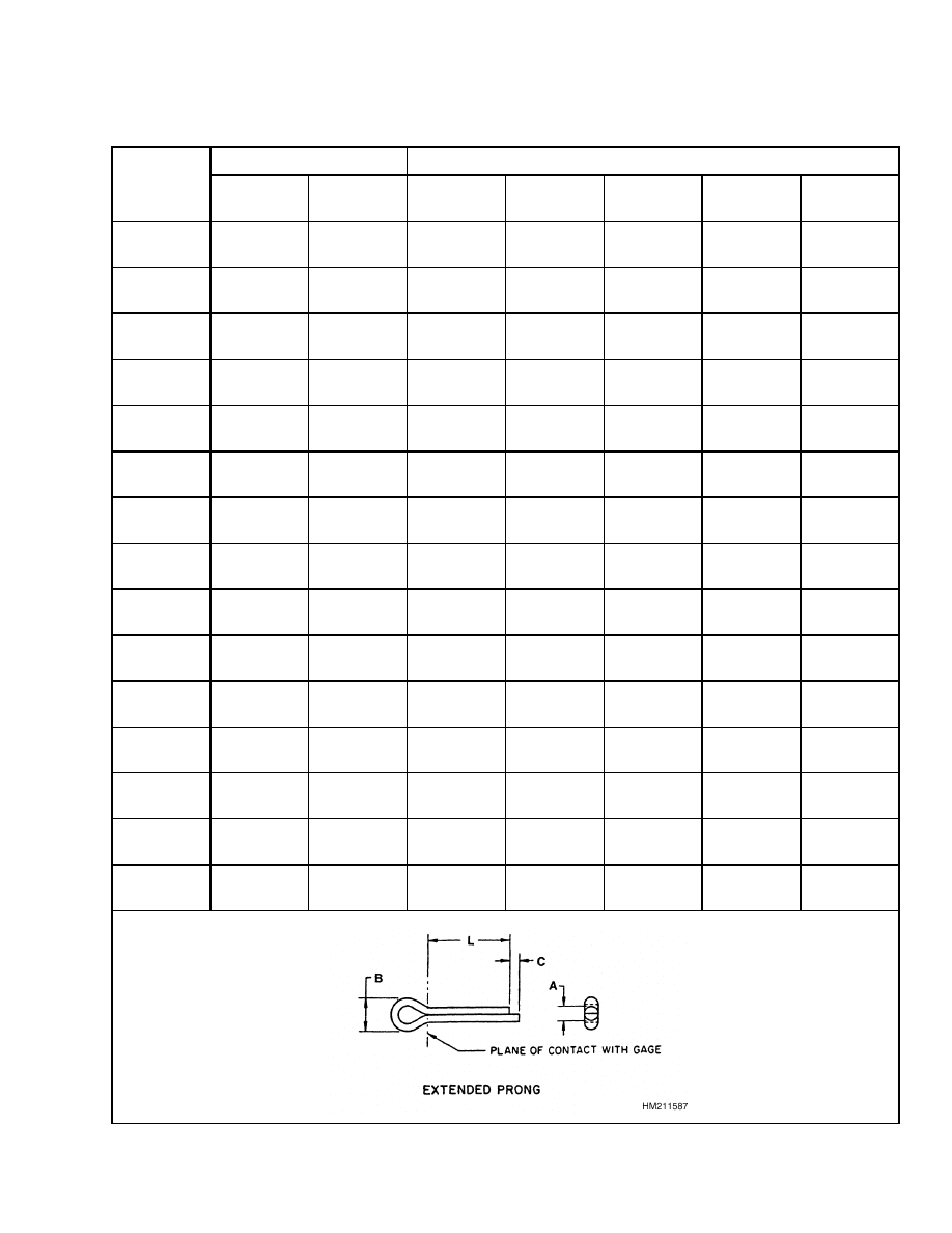
Table 9. Cotter Pin Dimensional Data
Length Range
Nominal Size - Part Numbers
Nominal
Length L
max
min
1.00 mm
(0.031 in.)
1.60 mm
(0.047 in.)
2.00 mm
(0.062 in.)
2.50 mm
(0.094 in.)
3.20 mm
(0.125 in.)
6.35 mm
(0.250 in.)
7.10 mm
(0.280 in.)
5.50 mm
(0.217 in.)
0221870
0221875
9.525 mm
(0.375 in.)
10.5 mm
(0.413 in.)
8.80 mm
(0.345 in.)
0221871
0221876
12.7 mm
(0.500 in.)
13.5 mm
(0.530 in.)
11.5 mm
(0.453 in.)
0221872
0221877
0015200
0015211
0015221
19.05 mm
(0.750 in.)
20.5 mm
(0.807 in.)
18.3 mm
(0.720 in.)
0221873
0221878
0015201
0015212
0015222
25.4 mm
(1.000 in.)
26.9 mm
(1.060 in.)
23.9 mm
(0.940 in.)
0221874
0221879
0015202
0015213
0015223
31.75 mm
(1.250 in.)
33.3 mm
(1.310 in.)
29.2 mm
(1.150 in.)
0015203
0015216
0015224
38.1 mm
(1.500 in.)
40.9 mm
(1.610 in.)
36.6 mm
(1.440 in.)
0015204
0015217
0015225
44.45 mm
(1.750 in.)
46.0 mm
(1.810 in.)
42.9 mm
(1.690 in.)
0015205
0015218
0015226
50.8 mm
(2.000 in.)
52.3 mm
(2.060 in.)
49.3 mm
(1.940 in.)
0015206
0015219
0015227
57.15 mm
(2.250 in.)
58.7 mm
(2.310 in.)
55.1 mm
(2.170 in.)
0015220
0056997
63.5 mm
(2.500 in.)
65.0 mm
(2.560 in.)
62.0 mm
(2.440 in.)
0221894
0015229
69.85 mm
(2.750 in.)
72.1 mm
(2.840 in.)
68.3 mm
(2.690 in.)
0015230
76.2 mm
(3.000 in.)
81.3 mm
(3.200 in.)
74.7 mm
(2.940 in.)
0015279
88.9 mm
(3.500 in.)
91.4 mm
(3.600 in.)
87.4 mm
(3.440 in.)
101.6 mm
(4.000 in.)
113.3 mm
(4.460 in.)
98.8 mm
(3.890 in.)
11
General
8000 SRM 231
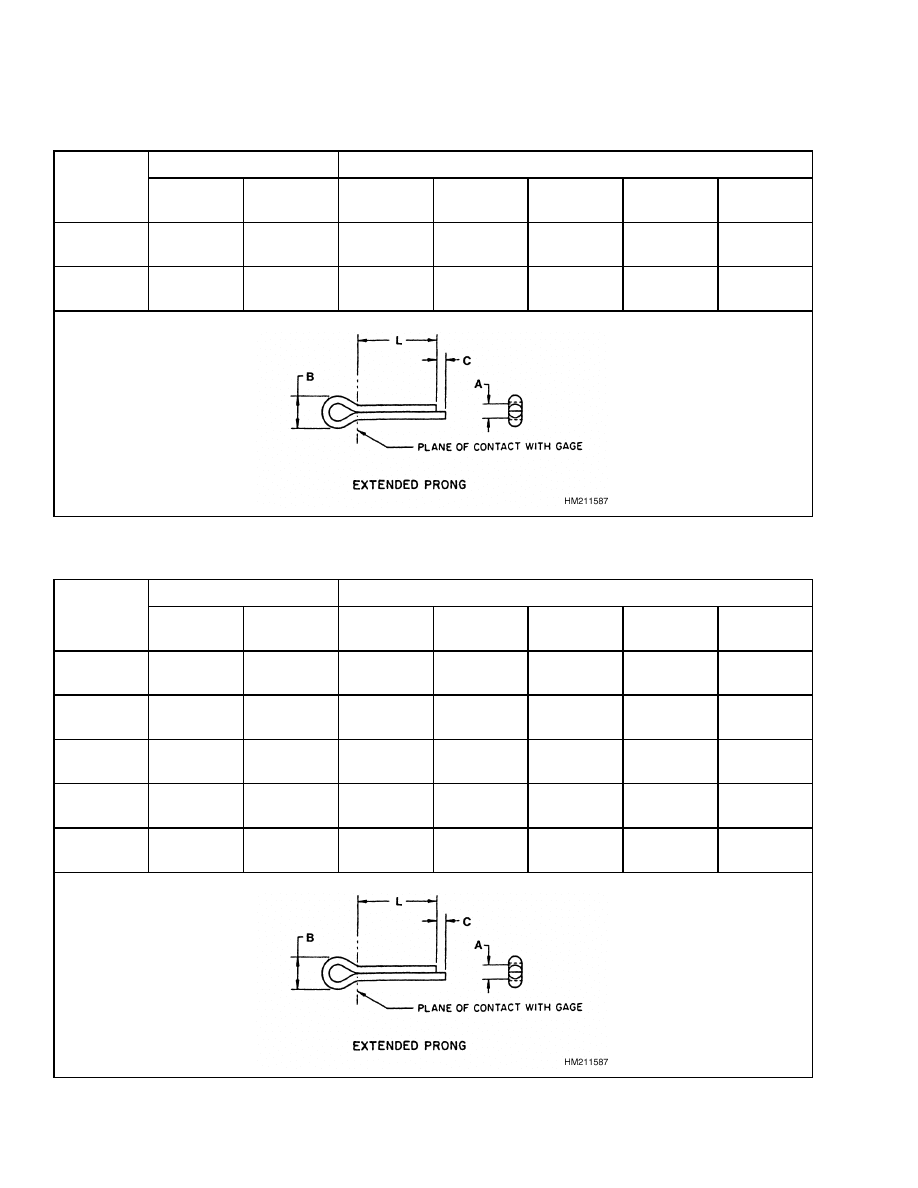
Table 9. Cotter Pin Dimensional Data (Continued)
Length Range
Nominal Size - Part Numbers
Nominal
Length L
max
min
1.00 mm
(0.031 in.)
1.60 mm
(0.047 in.)
2.00 mm
(0.062 in.)
2.50 mm
(0.094 in.)
3.20 mm
(0.125 in.)
127.0 mm
(5.000 in.)
128.5 mm
(5.060 in.)
123.7 mm
(4.870 in.)
152.4 mm
(6.000 in.)
153.9 mm
(3.060 in.)
5.460 mm
(138.7 in.)
Table 10. Cotter Pin Dimensional Data
Length Range
Nominal Size - Part Numbers
Nominal
Length L
max
min
4.00 mm
(0.156 in.)
5.00 mm
(0.188 in.)
6.30 mm
(0.250 in.)
8.00 mm
(0.312 in.)
9.52 mm
(0.375 in.)
6.35 mm
(0.250 in.)
7.10 mm
(0.280 in.)
5.50 mm
(0.217 in.)
9.525 mm
(0.375 in.)
10.5 mm
(0.413 in.)
8.80 mm
(0.345 in.)
12.7 mm
(0.500 in.)
13.5 mm
(0.530 in.)
11.5 mm
(0.453 in.)
19.05 mm
(0.750 in.)
20.5 mm
(0.807 in.)
18.3 mm
(0.720 in.)
0015232
0015241
25.4 mm
(1.000 in.)
26.9 mm
(1.060 in.)
23.9 mm
(0.940 in.)
0015233
0015242
0015251
0015261
12
8000 SRM 231
General
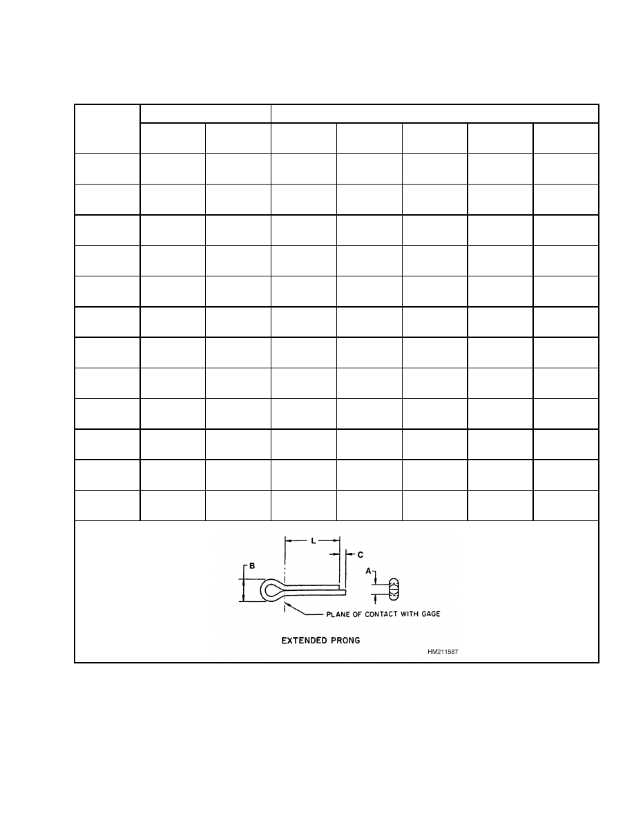
Table 10. Cotter Pin Dimensional Data (Continued)
Length Range
Nominal Size - Part Numbers
Nominal
Length L
max
min
4.00 mm
(0.156 in.)
5.00 mm
(0.188 in.)
6.30 mm
(0.250 in.)
8.00 mm
(0.312 in.)
9.52 mm
(0.375 in.)
31.75 mm
(1.250 in.)
33.3 mm
(1.310 in.)
29.2 mm
(1.150 in.)
0015234
0015243
0015252
0015262
0221884
38.1 mm
(1.500 in.)
40.9 mm
(1.610 in.)
36.6 mm
(1.440 in.)
0015235
0015244
0015253
0015263
0221885
44.45 mm
(1.750 in.)
46.0 mm
(1.810 in.)
42.9 mm
(1.690 in.)
0015236
0015245
0015254
0015264
0221886
50.8 mm
(2.000 in.)
52.3 mm
(2.060 in.)
49.3 mm
(1.940 in.)
0015237
0015246
0015255
0015265
0015271
57.15 mm
(2.250 in.)
58.7 mm
(2.310 in.)
55.1 mm
(2.170 in.)
0015238
0015247
0015256
0221880
0221887
63.5 mm
(2.500 in.)
65.0 mm
(2.560 in.)
62.0 mm
(2.440 in.)
0015240
0015248
0015257
0221881
0015273
69.85 mm
(2.750 in.)
72.1 mm
(2.840 in.)
68.3 mm
(2.690 in.)
0015280
0015249
0015258
0221882
0015286
76.2 mm
(3.000 in.)
81.3 mm
(3.200 in.)
74.7 mm
(2.940 in.)
0015283
0015250
0015259
0015267
0015272
88.9 mm
(3.500 in.)
91.4 mm
(3.600 in.)
87.4 mm
(3.440 in.)
0015239
0015284
0015266
0015274
101.6 mm
(4.000 in.)
113.3 mm
(4.460 in.)
98.8 mm
(3.890 in.)
0015301
0015260
0128754
0015275
127.0 mm
(5.000 in.)
128.5 mm
(5.060 in.)
123.7 mm
(4.870 in.)
0221883
0015277
152.4 mm
(6.000 in.)
153.9 mm
(3.060 in.)
5.460 mm
(138.7 in.)
0221888
13
General
8000 SRM 231
Table 11. Cotter Pin Dimensional Data
Length Range
Nominal Size - Part Numbers
Nominal Length
L
max
min
13.0 mm
(0.500 in.)
16.00 mm
(0.625 in.)
19.05 mm
(0.750 in.)
20.5 mm
(0.807 in.)
18.3 mm
(0.720 in.)
25.4 mm
(1.00 in.)
26.9 mm
(1.060 in.)
23.9 mm
(0.940 in.)
31.75 mm
(1.250 in.)
33.3 mm
(1.310 in.)
29.2 mm
(1.150 in.)
38.1 mm
(1.500 in.)
40.9 mm
(1.610 in.)
36.6 mm
(1.440 in.)
44.45 mm
(1.750 in.)
46.0 mm
(1.810 in.)
42.9 mm
(1.690 in.)
0221889
50.8 mm
(2.000 in.)
52.3 mm
(2.060 in.)
49.3 mm
(1.940 in.)
0221890
57.15 mm
(2.250 in.)
58.7 mm
(2.310 in.)
55.1 mm
(2.170 in.)
0221891
63.5 mm
(2.500 in.)
65.0 mm
(2.560 in.)
62.0 mm
(2.440 in.)
0221892
69.85 mm
(2.750 in.)
72.1 mm
(2.840 in.)
68.3 mm
(2.690 in.)
0221893
0221895
76.2 mm
(3.000 in.)
81.3 mm
(3.200 in.)
74.7 mm
(2.940 in.)
0015291
0221896
88.9 mm
(3.500 in.)
91.4 mm
(3.600 in.)
87.4 mm
(3.440 in.)
0015292
0221897
101.6 mm
(4.000 in.)
113.3 mm
(4.460 in.)
98.8 mm
(3.890 in.)
0015293
0221898
14
8000 SRM 231
General
Table 11. Cotter Pin Dimensional Data (Continued)
Length Range
Nominal Size - Part Numbers
Nominal Length
L
max
min
13.0 mm
(0.500 in.)
16.00 mm
(0.625 in.)
127.0 mm
(5.000 in.)
128.5 mm
(5.060 in.)
123.7 mm
(4.870 in.)
0015295
0221899
152.4 mm
(6.000 in.)
153.9 mm
(3.060 in.)
138.7 mm
(5.460 in.)
0015297
0221900
15

NOTES
____________________________________________________________
____________________________________________________________
____________________________________________________________
____________________________________________________________
____________________________________________________________
____________________________________________________________
____________________________________________________________
____________________________________________________________
____________________________________________________________
____________________________________________________________
____________________________________________________________
____________________________________________________________
____________________________________________________________
____________________________________________________________
____________________________________________________________
____________________________________________________________
____________________________________________________________
____________________________________________________________
____________________________________________________________
____________________________________________________________
16


TECHNICAL PUBLICATIONS
8000 SRM 231
12/04 (3/04)(3/03)(9/00)(3/98)(6/83) Printed in United Kingdom
Document Outline
- toc
- tables
- Table 1. Bolts and Screws
- Table 2. Studs and Nuts
- Table 3. Torque Nuts
- Table 4. Torque Nuts With Nylon Insert
- Table 5. Torque Values for Metric Fasteners*
- Table 6. Torque Values for Inch Fasteners*
- Table 7. Conversion Table for Metric and English Units
- Table 8. Cotter Pin Dimensional Data
- Table 9. Cotter Pin Dimensional Data
- Table 10. Cotter Pin Dimensional Data
- Table 11. Cotter Pin Dimensional Data
Wyszukiwarka
Podobne podstrony:
1554635 8000SRM1079 (06 2004) UK EN
1452930 8000SRM0680 (12 2002) UK EN
1565454 8000SRM1113 (06 2004) UK EN
1554636 8000SRM1080 (11 2004) UK EN
1494143 2200SRM0939 (12 2004) UK EN
1456997 8000SRM0708 (10 2004) UK EN
1467764 8000SRM0738 (05 2004) UK EN
1483865 8000SRM0916 (12 2003) UK EN
897001 8000SRM0291 (12 1993) UK EN
1553986 8000SRM1083 (05 2004) UK EN
1554635 8000SRM1079 (06 2004) UK EN
więcej podobnych podstron