
INFLUENCE OF SURFACE ENGINEERING ON
THE PERFORMANCE OF TOOL STEELS FOR
DIE CASTING
A. Persson and J. Bergstr¨om
Department of Materials Engineering
Karlstad University
SE-651 88 Karlstad
Sweden
S. Hogmark
The ˚Angstr¨om Laboratory
Uppsala University
SE-751 21 Uppsala
Sweden
Abstract
Thermal fatigue cracking and wear by erosion and corrosion are important
life-limiting failure mechanisms in die casting dies. To develop new and more
resistant tool materials for this application detailed knowledge of the casting
conditions, the failure mechanisms and their aggressiveness are essential.
Experimental simulations have successfully been applied to study the failure
mechanisms and also to evaluate the resistance of tool steels and surface
engineered materials against failure in die casting.
This study elucidates the thermal conditions during actual die casting of
brass. In addition, thermal fatigue and corrosive wear of surface engineered
hot work tool steel specimens were experimentally evaluated. Thermal fa-
tigue cracking was evaluated for the following conditions of a hot work tool
steel: quenched and tempered (reference), treated by boriding and Toyota dif-
fusion (CrC), respectively, PVD CrN-coated and duplex-treated topped with
a PVD CrN-coating, respectively. A special study of corrosive wear of CrN
PVD coatings applied on hot work tool steel specimens after treatment in an
aluminium melt was also performed.
1003

1004
6TH INTERNATIONAL TOOLING CONFERENCE
Temperature profiles in the surface layer of the mould were recorded and
details of the thermal cycling during actual die casting were obtained. With
the exception of duplex-treatment, all variants of surface engineering had
a tendency to decrease the resistance against thermal fatigue cracking as
compared to the reference steel. The mechanisms of initiation and progress
of liquid aluminium corrosion of CrN coated tool steels have been explained.
The corrosion resistance of CrN coatings improve with the coating thickness.
Finally, since the duplex-treated PVD CrN coating shows a high resistance to
surface cracking, and the corrosion resistance can be significantly improved
by CrN coatings, it is concluded that there is a potential to improve life and
performance of die casting tools by surface engineering.
Keywords:
Thermal fatigue, Corrosive wear, Failure, Temperature, Die casting.
INTRODUCTION
Die casting involves injection of molten metal, for example aluminium,
zinc, magnesium and copper based alloys, into a mould [1, 2, 3]. Prior
to casting aluminium and copper alloys, the die is normally preheated to
a temperature of 250-300℃ and 300-350℃, respectively, and the average
temperature is usually kept at those levels through internal cooling. High
velocity of the liquid metal during injection provides rapid filling of the die
cavity. For aluminium alloys, the entrance velocity during injection of the
melt is typically 20-60 m/s and the melt temperature is approximately 700℃,
whereas those for copper alloys is about 1-10 m/s and approximately 970℃.
When the casting has solidified, the die is opened and the casting is ejected.
Thereafter, the die may be externally cooled and lubricated by spraying. Hot
work tool steels, such as AISI H11, H13, H21 or H22, are frequently used
as die materials.
The life and performance of die casting dies is limited because of a num-
ber of reasons such as thermal fatigue cracking (heat checking), erosion,
corrosion, local adherence of the casting alloy to the tool (soldering), and
gross fracture [1, 2, 3]. Thermal fatigue cracking results from the cycling
of the tool temperature, which may induce stresses high enough to impose
plastic strain in the tool surface during each cycle. Surface cracks appear
already after a few thousand castings, or even earlier, and are, therefore,
formed in the low-cycle fatigue range [4]. However, it is reported that creep
and oxidation may significantly contribute to cracking [5, 6, 7]. The thermal
fatigue damage is often observed as a network of fine cracks on the tool

Influence of Surface Engineering on the Performance of Tool Steels for Die Casting
1005
surface. Erosion is induced by the high velocity of the incoming melt and
partially due to solid particles in the molten casting alloy. The erosive dam-
age is primarily seen where the molten metal jet first hits the die surface.
Corrosion damage originates from dissolution of the tool material into the
liquid metal. Erosion and corrosion may cause significant loss of surface
material. The mentioned failure mechanisms degrade the surface finish and
geometrical tolerances of the tool and, therefore, also those of the cast prod-
ucts, and may eventually cause rejection of the casting. Consequently, die
failure increases the production costs.
Surface engineering is today successfully introduced to improve the ero-
sion and corrosion resistance as well as to reduce soldering of dies and die ma-
terials [8, 9, 10, 11, 12, 13, 14, 15]. In addition, it has been shown that surface
engineered materials may show increased or decreased resistance to thermal
fatigue cracking as compared to untreated materials [11, 12, 13, 14, 15].
However, the mechanisms behind these discrepancies are not fully under-
stood. Experimental techniques have successfully been utilised to study
failure mechanisms and also to evaluate the resistance of tool steels and
surface engineered materials.
To develop new and more resistant tool materials for die casting detailed
knowledge of the casting conditions, the failure mechanisms as well as their
aggressiveness are essential. In this study, the temperature variations in the
surface layer of hot work tool steel, as heat treated or surface engineered,
were experimentally recorded during actual brass die casting. Thermal fa-
tigue and corrosive wear of surface engineered hot work tool steel specimens
were experimentally evaluated. Various types of surface engineering were
studied including surface treatment (boriding and Toyota diffusion to give
CrC) and physically vapour deposited (PVD) coatings of CrN used as a
single-layer or as the top layer in duplex-treatment (nitriding followed by
PVD coating). The untreated hot work tool steel was used as a reference
material. Corrosive wear of PVD coatings of CrN applied on hot work tool
steel specimens and treated in an aluminium melt was also studied.

1006
6TH INTERNATIONAL TOOLING CONFERENCE
EXPERIMENTAL
TEMPERATURE RECORDING DURING ACTUAL DIE
CASTING OF BRASS
Field test equipment.
For the temperature measurements, a relatively
simple tool used for production of tube couplings in brass was selected.
It was used in a 1.5 MN cold chamber machine in actual production runs.
The temperature of the brass melt was 980℃ and the total cycle time 30 s
during which the die was closed 10 s and open 20 s. Water at 20℃ was
continuously circulated through cooling channels in the tool. In addition,
the tool surfaces were lubricated but not intentionally cooled by spraying.
The total shot weight of each casting was 1.6 kg, the peak casting pressure
164 MPa, and the entrance velocity of the melt was about 1.5 m/s. Note that
the tool in this study was not preheated.
Four cylindrical measurement probes (∅ 16 mm) were designed, each
including a small cylindrical test specimen (∅ 8 mm) and a K-type (Chromel-
Alumel) thermocouple with thin wires (∅ 0.13 mm), spot welded to the back
of the specimen. The thin wires enable rapid response of any change in
temperature. The thickness of the four test specimens was 0.25, 0.50, 2.0
and 5.0 mm, respectively. Consequently, the temperature variations at these
depths below the surface are obtained. A hot work tool steel (Uddeholm
QRO 90 Supreme) of about 520 HV
30
was used both in the tool and the
probes.
The temperature data was collected simultaneously from all thermocou-
ples with a sampling rate of 500 Hz, using a customised data acquisition
system. More information is presented elsewhere [16].
Materials.
A hot work tool steel, Uddeholm QRO 90 Supreme, with the
nominal chemical composition (wt. %) 0.38 C, 0.30 Si, 0.75 Mn, 2.6 Cr,
2.25 Mo, 0.9 V and Fe balance, was used as test material. The specimens
were hardened and tempered (austenitizing 30 min at 1030℃ and tempering
2 × 2 h at 625℃) to a hardness of 500 ± 5 HV
30
.
The same steel, heat treated as above, was also borided (∼25 h at ∼850℃)
and CrN-coated by PVD, respectively. Prior to surface engineering, the
specimens were ground and polished with 1µm diamond paste in the last
step. The boriding process was followed by the same heat treatment as above.
The PVD-CrN coating was applied to the hardened and tempered steel, at

Influence of Surface Engineering on the Performance of Tool Steels for Die Casting
1007
a process temperature of 300℃. All treatments resulted in a martensitic
microstructure for the steel. The thickness of the diffusion zone profile of
the borided specimens was 27 ± 4 µm, and the PVD coating thickness was
4.6 ± 0.3 µm.
The brass cast alloy CuZn33Pb2Si-C (Ametal C, Tour & Andersson des-
ignation) was used in the tests. It has a nominal liquidus temperature of
887℃ and a solidus temperature of 844℃, and an approximate chemical
composition (wt. %), obtained by X-ray spectroscopy on a casting, of 64.1
Cu, 32.3 Zn, 1.9 Pb, 0.71 Si, 0.35 Fe, 0.05 As, 0.03 Al. More information
is presented elsewhere [16].
THERMAL FATIGUE TESTS
Materials.
A hot work tool steel, Uddeholm QRO 90 Supreme, with the
nominal chemical composition (wt. %) 0.38 C, 0.30 Si, 0.75 Mn, 2.6 Cr,
2.25 Mo, 0.9 V and Fe balance, was used as test material. The reference
specimens were hardened and tempered (austenitizing 30 min at 1030℃ and
tempering 2×2 h at 625℃), followed by fine grinding to a surface roughness
(R
a
) of 0.38 ± 0.05 µm.
Prior to surface engineering, the specimens were ground and polished with
1 µm diamond paste in a last step to a surface roughness (R
a
) of 20 ± 14 nm.
The specimens were surface treated by boriding (∼25 h at ∼850℃), Toy-
ota diffusion to generate CrC (TDP CrC) (6 h at 1030℃) or plasma nitriding
(15 h at 480℃), to produce a diffusion zone without any iron nitride com-
pound layer. The boriding process was followed by hardening and tempering
(at 1030℃ and 2 × 2 h at 625℃, respectively), while the TDP treatment was
followed by tempering 2 h at 625℃ and 2 h at 600℃. All plasma nitrided
specimens were duplex-treated with a PVD CrN coating on top of the ni-
trided layer. The PVD CrN coatings were produced in a multi-arc process,
with a deposition temperature of 300-400℃. The five treatments resulted in
different mechanical properties, see Table 1. More information is presented
elsewhere [17].
Thermal fatigue testing.
The test specimens are hollow cylinders with
a diameter of 10 mm and a length of 80 mm, and have a 3 mm axial hole
for internal cooling. An induction unit (25 kW, 3 MHz) heats the specimen
surface. Continuous cooling is performed internally by circulating silicon
oil of 60℃ through the specimen, but also externally with argon, which also

1008
6TH INTERNATIONAL TOOLING CONFERENCE
Table 1.
Mechanical properties of the test materials
Ref.
Boriding
TDP CrC
PVD CrN
Nitr.+PVD
CrN
Substrate hardness
[HV
30
]
507 ±4
520 ±2
522 ±2
495 ±1
507 ±2
Surface hardness
[HV
0
.
025
]
—
1740 ±100
1970 ±70
2000 ±100
2060 ±100
Nitriding hardness
[HV
0
.
025
]
—
—
—
—
915 ±15
Diffusion depth
[ µm ]
—
30 ±2
30 ±2
—
160 ±3
Coating thickness
[ µm ]
—
—
—
6.1 ±0.1
4.5±0.2
decreases oxidation during the thermal cycling. The specimen surface rep-
resents the surface of the die and the induction heating and cooling simulates
the temperature cycles during die casting.
Two temperature cycles were used to simulate aluminium and brass die
casting conditions, respectively. They include a steep ramp to the maximum
temperature, followed by a short hold time (<0.1 s), and subsequent cooling
to the minimum temperature. To simulate aluminium and brass die casting,
the maximum temperatures were set to 700℃ and 850℃, respectively. The
minimum temperature for both cycles was set to 170℃. The heating times
in the 700℃ and 850℃ cycles were 0.4 and 2.5 s, respectively, and the total
cycle times were 14.4 and 26.5 s, respectively.
Prior to testing, the specimens were pre-oxidised in order to get a thin ox-
ide layer, which facilitates the pyrometer temperature control during heating.
More information is presented elsewhere [17, 18].
CORROSION TESTS
Materials.
The substrate material used in the test specimens was a pre-
mium grade AISI H13 hot work tool steel, ORVAR SUPREME (Uddeholm
Tooling designation), with the nominal chemical composition (wt. %) 0.39
C, 1.0 Si, 0.4 Mn, 5.2 Cr, 1.4 Mo, 0.9 V and Fe balance. Prior to coating the
steel was hardened and tempered to a nominal hardness of 45–48 HRC. The

Influence of Surface Engineering on the Performance of Tool Steels for Die Casting
1009
Table 2.
Substrate temperature, deposition time and resulting thickness of the CrN coatings
Designation
Substrate temperature
Deposition time
Coating thickness
[℃ ]
[min]
[ µm ]
LL
230
50
2.9 ±0.2
LH
230
175
13.6 ±0.4
ML
280
50
4.2 ±0.3
MH
325
175
20.1 ±1.4
HL
440
40
3.2 ±0.3
HH
430
70
18.9 ±1.1
aluminium alloy used in the tests was ISO Al-Si8Cu3Fe with the nominal
chemical composition (wt. %) 3 Cu, <1.2 Fe, 9 Si and Al balance. This
alloy is similar to the common die casting alloy AA380.0.
The PVD CrN coatings were made in a similar way to those of the thermal
fatigue test. By varying the substrate temperature and deposition time, see
Table 2, six coating series were produced, representing six combinations of
coating thickness and defect density. Of the coating designations given in
Table 2, L denotes both low temperature and short time, M denotes medium
temperature, and H represents both high temperature and long deposition
time. Each series consisted of five specimens, except test series HH, which
consisted of three. More information is presented elsewhere [19].
Corrosion testing.
The experimental set-up consisted of a resistively
heated crucible for the aluminium melt, and a circular specimen holder for
three specimens, and a thermocouple. The melt temperature was controlled
to 710 ± 10℃. To maintain uniform temperature and concentration dur-
ing testing, the liquid aluminium was stirred by a ceramic plate rotating at
80 rev./min. Cylindrical specimens, 90 mm in length, 13 mm in diameter,
and with the tip rounded to a 6.5 mm radius, were used. During each test
three specimens and the thermocouple were clamped symmetrically in the
circular specimen holder and submerged 1 h in the liquid aluminium. More
information is presented elsewhere [19].

1010
6TH INTERNATIONAL TOOLING CONFERENCE
RESULTS
RECORDED TEMPERATURE PROFILES IN ACTUAL
BRASS DIE CASTING
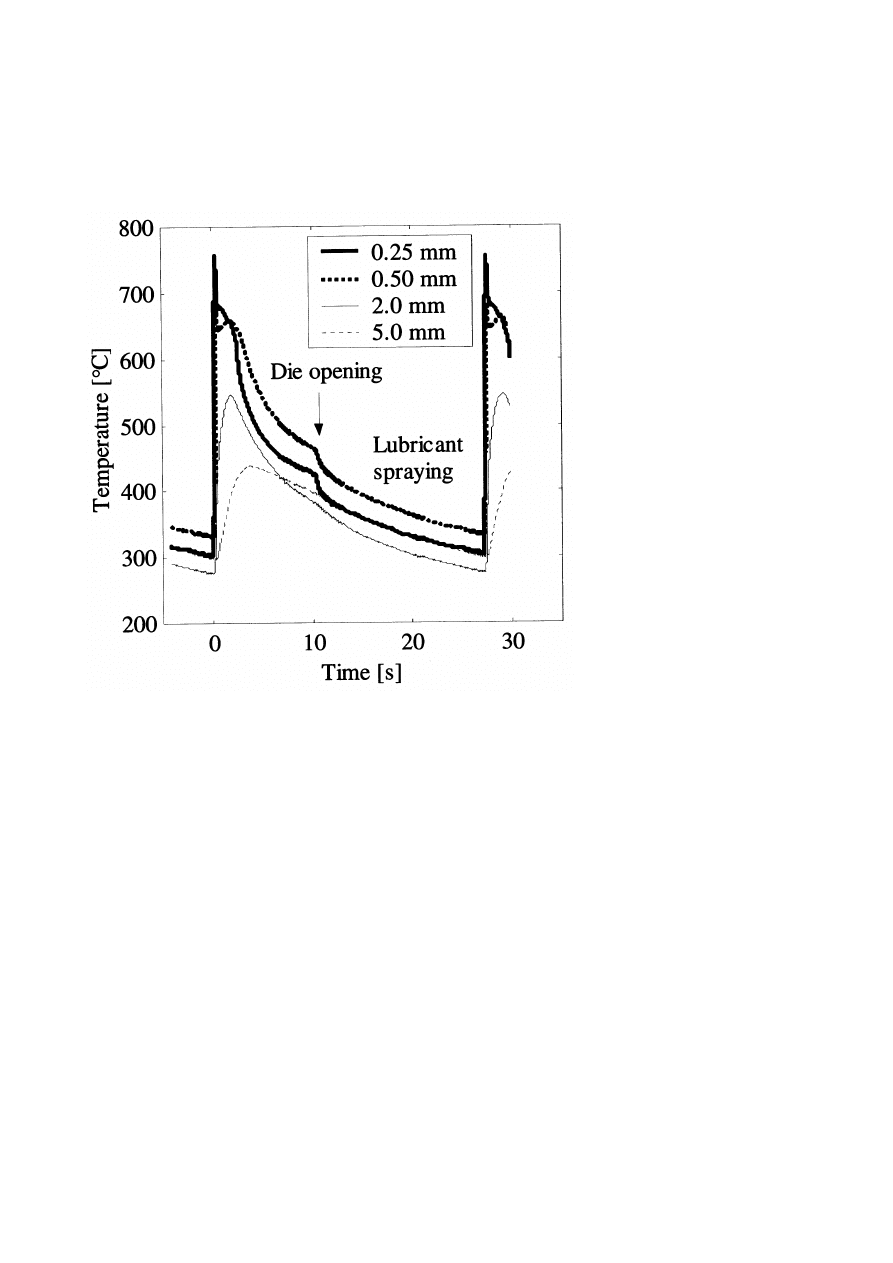
The measured temperature profiles consisted typically of a steep ramp
from the minimum to the maximum temperature, followed by a more gradual
decrease in temperature. During the first cycles (less than 20), the minimum
temperature increases from room temperature to about 300℃, where after
the temperature cycles are almost identical. A representative temperature
recording after equilibrium is shown in Fig. 1. As expected, the maximum
temperature and the heating time were strongly dependent on the distance
from the surface, while the minimum temperature appeared to be relatively
independent of the depth. Note that the minimum temperature is approxi-
mately the same at the beginning and at the end of a cycle at each depth in
the tool which proves that steady-state is reached. Finally, note that the tem-
perature decreases rapidly, especially near the surface when the die opens
and the casting is ejected. No additional cooling effect from the lubrication
can be observed.
The thin surface layers from the boriding or CrN treatment did not have
any notable effect on the thermal conditions.
SURFACE CRACKING AFTER THERMAL FATIGUE
TEST
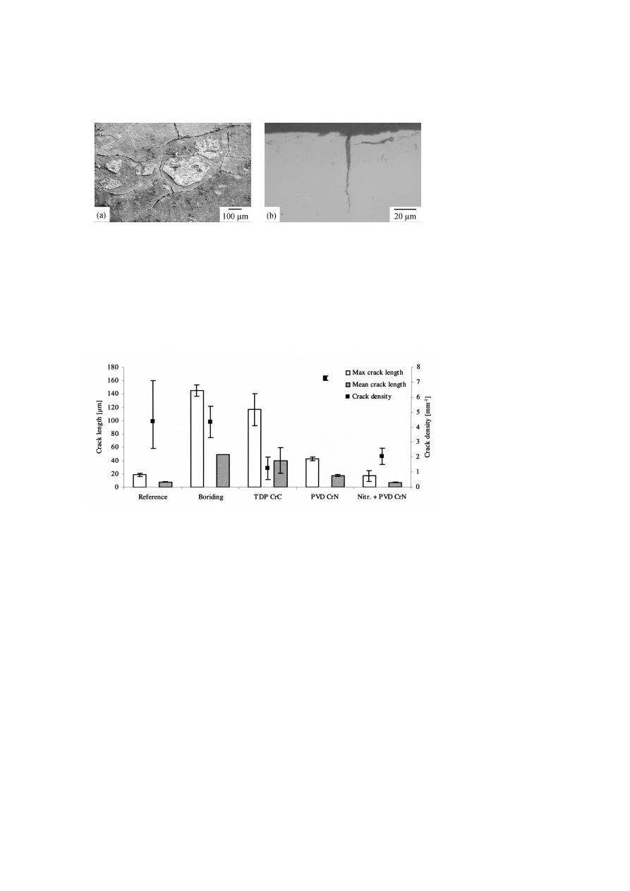
Thermal fatigue cracking of the surface engineered tool steel after thermal
cycling is exemplified in Figs. 2a and 2b. The crack growth was strongly
dependent on the number of cycles, and it was significantly faster during the
850℃ cycles as compared to the 700℃ cycles. The resistance to cracking
(as maximum and mean length of cracks such as that of Fig. 2b and crack
density (as number of cracks per unit of length) differs significantly between
the surface engineerings, see Fig. 3. It is seen that the boriding, TDP, and
CrN coating show a tendency to impair the resistance to thermal fatigue
cracking as compared to the reference material. It is also seen that the
duplex-treatment proved comparable to the reference material, but gave an
increased resistance to surface cracking as well as a reduced density of cracks
as compared to the single-layered CrN coating.
Influence of Surface Engineering on the Performance of Tool Steels for Die Casting
1011
Figure 1.
Typical temperature profiles at different depths from the surface obtained at
steady-state condition (Boronized specimens at cycle 20.).
1012
6TH INTERNATIONAL TOOLING CONFERENCE
(a) Typical crack network after 10 000 cycles
(scanning electron microscopy, SEM).
(b) Cross-section after 5 000 cycles (light op-
tical microscopy, LOM).
Figure 2.
Example of thermal fatigue cracking after treatment with the 700℃ cycle
(borided specimens).
Figure 3.
Maximum and mean crack length as well as crack density after 5 000 cycles to
700℃. Three reference specimens and two specimens of each treatment were tested. The
error bars indicate the maximum and minimum value.

Influence of Surface Engineering on the Performance of Tool Steels for Die Casting
1013
(a) Top view.
(b) Fractured cross-section.
Figure 4.
Typical bulge formation during the corrosion test after removal of solidified
aluminium (SEM).
COATING CHARACTERISTICS AFTER CORROSION
TEST
Coating damage in the form of localised circular bulges was frequently
detected by SEM, see Fig. 4a. Fractured cross-sections revealed a corrosive
attack on the substrate material under the bulge, see Fig. 4b. Note the pinhole
defects in the centre of the bulges.
Macroscopic corrosive damage was observed in the SEM as local corro-
sion pits in the coating surface, see Fig. 5a. Note that the damage consists of
circular corrosion pits, as well as pits that have grown together and formed
larger cavities. Local areas without any detected corrosive attack on the
coating material was observed even though the loss of the coating was large,
see Fig. 5b.
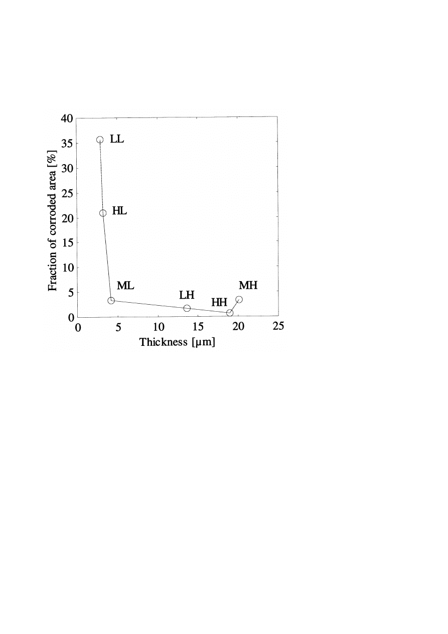
The fraction of corroded area occupied by the pits differs significantly
between the series, see Fig. 6. It is seen that the thick coatings (group LH,
MH and HH) show a low amount of corroded area, while the thin coatings
except ML show a high fraction.
DISCUSSION
TEMPERATURE CYCLING OF DIE SURFACE
DURING ACTUAL BRASS DIE CASTING
A typical heat distribution in the tool surface layer during one casting cycle
is seen in Fig. 1. When the 980℃ melt makes contact with the tool, the tool

1014
6TH INTERNATIONAL TOOLING CONFERENCE
(a) Overview revealing the type of bulge forma-
tion seen in Fig. 4, local corrosion pits, and larger
corroded areas.
(b) Local coating island without any corrosive
damage (indicated by the arrow).
Figure 5.
Macroscopic corrosive damage of the coated material identified after removal
of solidified aluminium (SEM).
material is heated within about 0.35 s from around 300℃ to a maximum
temperature of around 750℃ at a depth of 0.25 mm. Deeper below the tool
surface the maximum temperature is lower, and the heating rate is reduced.
Until the tool is opened, cooling occurs by heat conduction into the bulk of
the tool. Die opening and simultaneous cast ejection give rise to an additional
heat loss through irradiation and convection, which naturally is most notable
at the 0.25 and 0.5 mm depths.
Detailed knowledge of the thermal cyclic nature in the surface layer of
a die casting tool during actual service conditions can be used to perform
realistic imitations of the heat cycling in, for example, experimental and
numerical simulations of thermal fatigue. Since the thermal cyclic conditions
is most severe during the first phase of the casting cycle (when the die is
closed, cp. Fig. 1), knowledge of the cyclic nature in the surface layer
during this period is of greatest interest. For the 0.25–5.0 mm surface layer,
the following approximate values were found: Maximum temperature 750-
450℃, minimum temperature ∼300℃, heating time 0.35-4 s, and heating
rate 1250–40℃/s.
From measured temperature profiles such as those of Fig. 1, the maximum
surface temperature and surface heat flux can be estimated to approximately
826℃ and about 9.8 MW/m
2
, respectively [16].
Influence of Surface Engineering on the Performance of Tool Steels for Die Casting
1015
Figure 6.
Fraction of corroded area vs. the coating thickness.

1016
6TH INTERNATIONAL TOOLING CONFERENCE
THERMAL FATIGUE CRACKING
In general, the boriding, TDP and CrN coating show a tendency to de-
crease the resistance to thermal fatigue cracking as compared to the reference
material, see Fig. 3. Additionally, the resistance to cracking among these
seems to increase with the surface hardness, which is indicated by the fact
that the density of cracks was significantly lower for the TDP than for the
borided material. To resist thermal cracking, a material should, for example,
have a high hot hardness or hot yield strength, but also sufficient ductility,
since the hot yield strength controls the plastic strain for a given temper-
ature cycle, and the ductility represents the ability to resist plastic strain
without cracking [2]. The engineered surfaces have higher hardness levels
than the reference material, and it is consequently expected that their hot
yield strength is higher and their ductility is lower than for the reference
material. However, the high deposition temperature of the boriding and the
TDP processes seem to deteriorate the mechanical properties of the substrate
more than the nitriding and PVD processes do, even if this is not reflected
by the substrate hardness numbers. This is supported by the fact that the
maximum crack lengths in the borided and TDP treated materials are well
beyond the diffusion depths. Consequently, the subsurface and substrate
properties are very different. However, the difference between the thermal
fatigue resistance and the crack density between the two categories of sur-
face engineering is explained by the combined effect of differences in plastic
response, residual stress state of the surface zone, as well as differences in
these properties of the substrate.
Finally, it is clearly demonstrated that the duplex-treatment results in
an increased resistance to surface cracking as well as a reduced density of
cracks as compared to the single-layered CrN coating, see Fig. 3. This
indicates that the plasma nitriding process prior to coating plays a dominant
role to inhibit crack initiation and to slow down the crack propagation. The
initiation and growth of cracks is probably slowed down as a consequence
of the increased strength and the compressive stresses generated in a zone
beneath the surface during plasma nitriding. Simplified, this reduces the
surface plastic strain and the tensile stress intensity range during thermal
cycling and, consequently, the driving force for crack initiation and growth.

Influence of Surface Engineering on the Performance of Tool Steels for Die Casting
1017
CORROSION
Previously, the corrosive damage of coated materials exposed to liquid
aluminium has been observed as local attacks in the form of corrosion pits,
while other areas seemed to be completely unaffected by the exposure. In
addition, it is indicated that the corrosion pits result from local coating defects
rather than from any intrinsic deficiency [9, 10]. Finally, the unaffected areas
between the corrosion pits (cp. Fig. 5) indicate that the coatings themselves
are inert to the exposure of liquid aluminium [9]. Since the coating material
is inert, the defects behind the corrosion must penetrate through the coating.
The mechanisms of initiation and progress of liquid aluminium corrosion
of CrN coated tool steels have previously been explained [9, 19]. It was
observed that the corrosive attack is initiated through pinhole defects, which
act as small channels for the liquid aluminium through the coating down
to the substrate (cp. Fig. 4), where intermetallic phase transformation and
volume expansion due to diffusion of aluminium occurred. The volume
below the defect continues to expand and local coating detachment occurs
when the deflection of the coating is excessively large. In the following, the
craters coalesce to aggravate the corrosion as evidenced by Fig. 5a [9].
From Fig. 6 it is evident that the resistance to corrosive wear is improved by
increasing the coating thickness. This is supported by previous observations
that the density of defects through the coating (pinhole defects) decrease
with increasing coating thickness [19].
CONCLUSIONS
In this study, the temperature variations in a surface layer of hot work tool
steel, as heat treated or surface engineered, were experimentally recorded
during actual brass die casting. In addition, thermal fatigue and corrosive
wear of surface engineered hot work tool steel specimens were experimen-
tally evaluated. The following main conclusions can be drawn.
The temperature profiles in the surface layer of the mould were ac-
curately recorded and details of the thermal cyclic conditions were
obtained.
Thermal fatigue cracking of a surface engineered tool steel is primarily
influenced by the modification of the mechanical properties of the
substrate which occurs during the engineering process.

1018
6TH INTERNATIONAL TOOLING CONFERENCE
With the exception of duplex-treatment, all variants of surface engi-
neering decrease the resistance to thermal fatigue cracking as com-
pared to the reference steel.
However, the fact that the duplex-treated PVD CrN coating increased
the resistance to thermal fatigue cracking as well as reduces the density
of cracks as compared to the single- layered CrN coating, the poten-
tial to improve the life and performance in for example die casting
applications still prevails.
Liquid aluminium corrosion of CrN coated tool steels occurs as fol-
lows. Initially, through-the-coating defects act as channels and cause
the liquid aluminium to locally attack the steel. The subsequently
formed corrosion pits coalesce and the corrosive attack aggravates.
The corrosion resistance of CrN coatings is improved by increasing
their thickness.
The fact that the defect free areas of the CrN coating did not show
any corrosion indicates that the potential of further improvement the
CrN/tool steel system is high.
Since the duplex-treated PVD CrN coating showed the highest resis-
tance to surface cracking, and the corrosion resistance can be signifi-
cantly improved by CrN coatings, there is a potential to improve life
and performance of die casting tools by surface engineering.
ACKNOWLEDGMENTS
The authors like to acknowledge the Swedish Knowledge Foundation,
Uddeholm Tooling AB, Tour & Andersson AB, and Bodycote Heat Treat-
ment AB for their financial and material support.
REFERENCES
[1] L.J.D. SULLY, in "Metals Handbook, 9th ed., vol. 15" (ASM International, Metals Park,
Ohio, 1988) p. 286.
[2] J.R. DAVIS (Ed.), in "ASM Speciality Handbook, Tool Materials" (ASM International,
Materials Park, Ohio, 1995) p. 251.
[3] D.F. ALLSOP, D. KENNEDY, in "Pressure diecasting, Part 2: The technology of the
casting and the die" (Pergamon Press Ltd, Oxford, 1983).

Influence of Surface Engineering on the Performance of Tool Steels for Die Casting
1019
[4] R. DANZER, F. STURM, A. SCHINDLER, W. ZLEPPNIG, Gisserei-Praxis, 19/20
(1983) 287.
[5] V.A. KOVRIGIN, B.S. STAROKOZHEV, S.A. YURASOV, Metal Science and Heat
Treatment, 22 (1980) 688.
[6] W. ZLEPPNIG, R. DANZER, F.D. FISCHER, K.L. MAURER, in Proceedings of the
6th Biennial European Conference on Fracture, Amsterdam, 1986, p. 1139.
[7] A.M. SCHINDLER, R.B. DANZER, in Proceedings of the International Conference
Step into the 90’s, 3, Queensland, 1986, p. 905.
[8] S. CHELLAPILLA, R. SHIVPURI, S. BALASUBRAMANIAM, in Transactions 19th
International Die Casting Congress and Exposition, Minneapolis, 1997, p. 295.
[9] M. SUNDQVIST, J. BERGSTR ¨
OM, T. BJ ¨
ORK, R. WESTERG˚ARD, in Transactions
19th International Die Casting Congress and Exposition, Minneapolis, 1997, p. 325.
[10] T. ARAI, in Transactions 18th International Die Casting Congress and Exposition,
Indianapolis, 1995, p. 327.
[11] C. MITTERER, F. HOLLER, F. USTEL, D. HEIM, Surface and Coatings Technology,
125 (2000) 233.
[12] C.M.D. STARLING, J.R.T. BRANCO, Thin Solid Films, 308-309 (1997) 436.
[13] Y. WANG, Surface and Coatings Technology, 94-95 (1997) 60.
[14] M. FACCOLI, G.M. LA VECCHIA, R. ROBERTI, A. MOLINARI, M. PELLIZZARI,
International Journal of Materials and Product Technology, 15 (2000) 49.
[15] M. PELLIZZARI, A. MOLINARI, G. STRAFFELINI, Surface and Coatings Technol-
ogy, 142-144 (2001) 1109.
[16] A. PERSSON, S. HOGMARK, J. BERGSTR ¨
OM, Submitted to Journal of Materials
Processing Technology.
[17] A. PERSSON, J. BERGSTR ¨
OM, C. BURMAN, S. HOGMARK, in Proceedings of the
10th International Conference on Fracture, Honolulu, 2001.
[18] A. PERSSON, J. BERGSTR ¨
OM, C. BURMAN, in Proceedings of the 5th International
Conference on Tooling, Leoben, 1999, p. 167.
[19] A. PERSSON, J. BERGSTR ¨
OM, C. BURMAN, S. HOGMARK, Surface and Coatings
Technology, 146-147 (2001) 42.
Wyszukiwarka
Podobne podstrony:
Effect of surface finish on the osseointegration of laser
Effect of magnetic field on the performance of new refrigerant mixtures
94 1363 1372 On the Application of Hot Work Tool Steels for Mandrel Bars
On the Performance of Internet Worm Scanning Strategies
On the Performance of Minimum Quantity Lubrication in Milling Al 6061
36 495 507 Unit Cell Models for Thermomechanical Behaviour of Tool Steels
78 1101 1109 Industrial Production of Tool Steels Using Spray Forming Technology
81 1147 1158 New Generation of Tool Steels Made by Spray Forming
45 625 642 Numerical Simulation of Gas Quenching of Tool Steels
6 63 76 Influence of Surface Heat Treatment on Thermal Fatique Behaviour
Influence of titanium surfaces on attachment of osteoblast
więcej podobnych podstron