s20e115 / 040114
1 / 2
Data
sheet
SL20 with remote shut-down
SL20.115
• Input: AC 115/230V auto select
• Output: 24...28V / 480W (600W)
• 90% efficiency
• Ideal for parallel operation
• Remote shut-down
Order information
Order number
Description
SL20.115
SLZ02
(wall mounting set; contains 2 pcs.)
CUL/CSA-C22.2
EMC and
Low Volt.
UL60950 E137006
UL508 LISTED
IND. CONT. EQ.
No 60950
18 WM, 60°C
Directive
CB
scheme
IEC60950
Type approval
• IEC / EN60950
• EN50178
• EN60204
acc. to:
Overvolt. cat. III
Input
Efficiency, Reliability
Further information
Output
(signal terminals see overleaf)
Construction / Mechanics
Input voltage
AC 100-120V/220-240V,
47-63Hz, auto select
Rated tolerances
• Continuous
operation
• Short-term (1 min)
at 24V/20A
AC 85...132V resp. AC 184...264V
AC 85...140V resp. AC 170...280V
Input current I
n
<10A (115V range); <5A (230V range)
Inrush current limiting with active bypass of the limiting resistor (NTC).
Inrush current I
pk
<18A @ AC 264V (T
amb
= +25°C, cold start)
<37A @ AC 264V (T
amb
= +50°C, cold start)
Fuse loading I²t
<5A
2
s (T
amb
= +25°C, cold start)
<8A
2
s (T
amb
= +50°C, cold start)
To be fused with a 16A, B-type 'circuit-breaker' switch based on the
usual thermomagnetic overload sensing principle (used anyway to fuse
the input lines).
EN 61000-3-2 (harmonic current emissions [PFC]) is fulfilled
Transient
handling
Transient resistance acc. to VDE 0160 / W2
(750V/1.3ms), for all load conditions.
Hold-up time
30ms at 24V/20A, AC 230V
in
30ms at 24V/20A, AC 120V
in
15ms at 24V/20A, AC 100V
in
Efficiency
typ. 90.5%
(AC 230V, 24V/20A)
Losses
typ. 50W
(AC 230V, 24V/20A)
MTBF
519.000h acc. to Siemensnorm SN29500
(24V/20A, 230V, T
amb
= 40°C)
Life cycle (electrolytics)
The unit exclusively uses longlife electrolytics,
specified for +105°C (cf. ’The SilverLine’, p.2).
High reliability, as
• only five aluminium electrolytics and
• no small aluminium electrolytics are used.
Further information, especially about
• EMC, Connections, Safety, Approvals, Mechanics and Mounting
see page 2 of the „The SilverLine“ data sheet.
• For detailed dimensions see SilverLine mechanics data sheet SL20.
Output voltage
DC 24...28V, adjustable by (covered) front pan-
el potentiometer. Adjust. range guaranteed.
Output noise
suppression
Radiated EMI values below EN50081-1, even
when using long, unscreened output cables.
Ambient temperature
range T
amb
Operation: 0°C...+70°C (>60°C: Derating)
Storage: -25°C...+85°C
Rated continuous loading with convection cooling:
• T
amb
=0°C - 60°C
24V/20A resp. 28V/18A
short-term (<30s) 24V/25A resp. 28V/22A
Derating 12W/K
(at
T
amb
= 60-70°C)
Voltage regulation
better than 2% over all
Ripple
• Output charact. S
• Output charact. P
(S/P: Single/Parallel Mode)
(incl. spikes (20MHz bandw.), 50
Ω measurem.
<20mV
PP
(<0.1%)
<40mV
PP
(In: AC 230V, Out: 24V/20A)
<100mV
PP
(In: AC 184V, Out: 24V/20A)
Over-voltage protection
At 33V ± 10%: switch to hiccup mode
Front panel indicators:
• Green LED on, when V
out
> U
T
, where U
T
is appr. 2V below V
out
adjusted (24V...28V)
• Red LED on, when V
out
< U
T
Parallel operation
Yes, up to ten SL20
To achieve current sharing the output V/I characteristic can be altered
to be 'softer' (25V at 0.4A, 24V at 20A). This is done by repositioning an
external bridge connection (without opening the unit).
Power Back Immunity
max. 30V
Housing dimensions and Weight
• W x H x D
• Free space for
ventilation
• Weight
220mm x 124mm x 102mm (+ DIN rail)
above/below 70mm recommended
left/right 25mm recommended
2,5kg
Design advantages:
• All connection blocks are easy to reach as mounted on the
front panel.
• PVC insulated cable can be used for all connections, as the connection
blocks are mounted in the cooler area on the underside of the unit.
Datasheet
Your partner in power supply:
European
Power Supply
Manufacturers
Association
PULS GmbH
Arabellastraße 15
D-81925 München
Tel.: +49 89 9278-0
www.puls-power.com
Fax: +49 89 9278-199
Data sheet
2 / 2
s20e115 / 040114
Bayerns Best 50
Czech 100 Best
Europe’s 500
Unless otherwise stated, specifications are valid for AC 230V input voltage, +25°C ambient temperature, and 5 min. run-in time. They are subject to change without prior notice.
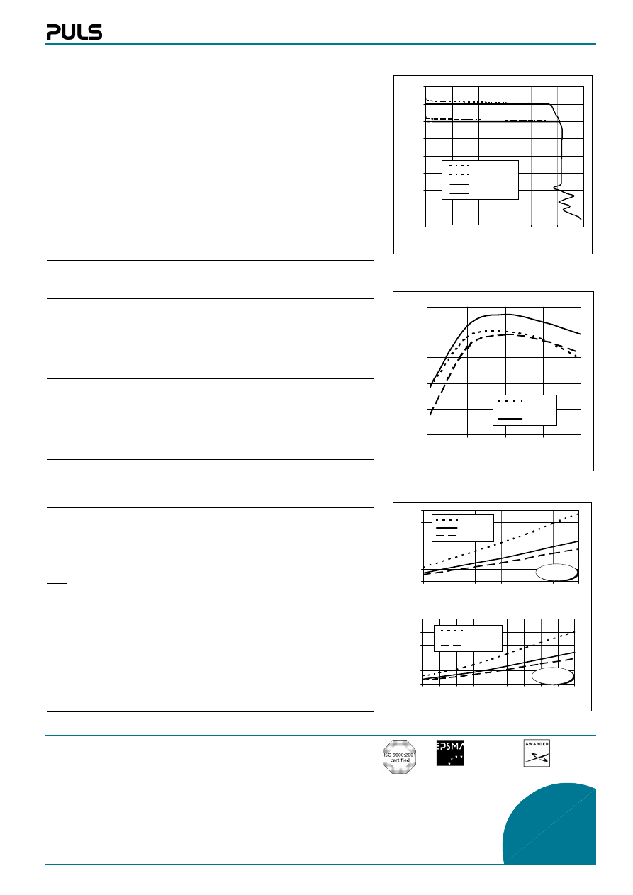
Start / Overload Behaviour
Signal terminals
Startup delay
typ. 0.55s
Rise time
appr. 20-80ms, depending on load
Overload behaviour
Puls Overload Design (see right-hand diagram)
Advantages:
• No disconnection/hiccup, thus overloading is possible also for a longer period of
time (load start-up), ideal for parallel operation.
• High overload/short-circuit current due to straight characteristic; each bias point of
the V/I characteristic extends 20A.
Advantage: Due to the high and continuously supplied overload current the unit starts
reliably even with awkward loads (DC-DC converters, motors). No 'sticking' can occur
as, for example, with fold-back characteristics, and secondary fuses trigger more relia-
bly.
The remote On/off control is activated via the signal terminals 'Remote Shutdown 1 and
2'. The unit is delivered with the signal terminals jumpered (control state is 'On' with
the terminals jumpered).
a) Remote shut-down by switch:
Unit turns on when the signal terminals 'Remote Shutdown 1 and 2' are closed by a
switch (R<10
Ω).
• Connect the switch contact with the signal terminals Remote Shutdown 1 and 2, on-
ly! Ensure the switch contact is not connected to the output voltage or in contact
with any separate voltages.
• Unit is in standby mode with open switch contact (R>100k
Ω)
b) Remote shut-down by control voltage:
Positive voltage is applied to 'Remote Shutdown 1' against minus output (reference po-
tential)
• Unit turns on, when positive voltage (3...30V, 0.3...2mA) is applied to 'Remote Shut-
down 1' against the minus output
• Unit switches off at <0.6V
• Input voltages of 0.6...3V and negative voltages are not defined
Parallel operation / cascading of outputs:
• Use a multi-pole switch with one switch contact for each power supply unit (1 x On);
connection of the signal terminals with one switch contact is not permissible when
being used in parallel operation
Additional control features with parallel operation:
Unit turns on:
• positive voltage (4...30V) is applied to 'Remote Shutdown 1' against negative output
voltage
Unit switches off:
• 0...0.5V
in
is applied to 'Remote Shutdown 1'
Note:
• Connection of the terminals 'Remote Shutdown 1' is possible with parallel opera-
tion; do not use the terminals 'Remote Shutdown 2'
• Only connect the signalling lines at one single point of the negative output voltage;
a voltage drop between the connection point and the minus terminals must not ex-
ceed 0.5V, even at maximum load!
Additional data regarding remote shut-down:
• Output current
< 5mA (mean)
• Power consumption
<2.5W
• Residual voltage at zero load
<3V
• Startup delay
<500ms
• Switching operations per min.
<10
0
4
8
12
16
20
24
28
32
0
5
10
15
20
25
30
Output current Iout [A]
O
u
tput voltage V
out [V
]
28V / Parallel
24V / Parallel
24V / Single
28V / Single
0
20
40
60
80
100
85
90
95 100 105 110 115 120 125 130
Input voltage VACin [V]
Hold-up time [ms]
60% load
100% load
125% load
0
10
20
30
40
50
60
180
190
200
210
220
230
240
Input voltage VACin [V]
H
old-up time [ms]
60% load
100% load
125% load
87
88
89
90
91
92
5
10
15
20
25
Output current Iout [A]
Efficiency [%]
100 VAC
120 VAC
230 VAC
Efficiency (typ., at V
out
=24V)
Hold-up time (min., at V
out
=24V)
Output characteristic (typ.)
at AC 230V
at AC 115V
Wyszukiwarka
Podobne podstrony:
Datasheet SL20 303
Datasheet SL20 100
Datasheet SL20 310
Datasheet SL20 300
Datasheet SL20 112
Datasheet SL20 113
Datasheet SL20 110
Datasheet SL20 303
Datasheet SL20 100
Datasheet SL4 100
Datasheet QS10 241 C1
więcej podobnych podstron