Siemens AG Österreich, 07/2007
1
of 8
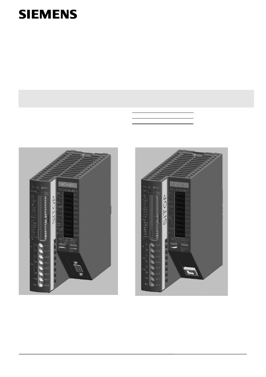
SITOP DC-USV-Modul 15
SITOP DC-USV-Modul 15
6EP1931-2EC21
SITOP
DC-UPS-Module
15
6EP1931-2EC31
6EP1931-2EC42
Betriebsanleitung Order No.: C98130-A7555-A2-07-7419
Operating Instructions
Manuel d'utilisation
voir Internet
http://www.siemens.de/sitop
Manuale di servizio
vedi Internet
http://www.siemens.de/sitop
Manual de instrucciones
véase Internet
http://www.siemens.de/sitop
6EP1931-2EC31
6EP1931-2EC42
Siemens AG Österreich, 07/2007
2
of 8
SITOP DC-USV-Modul 15
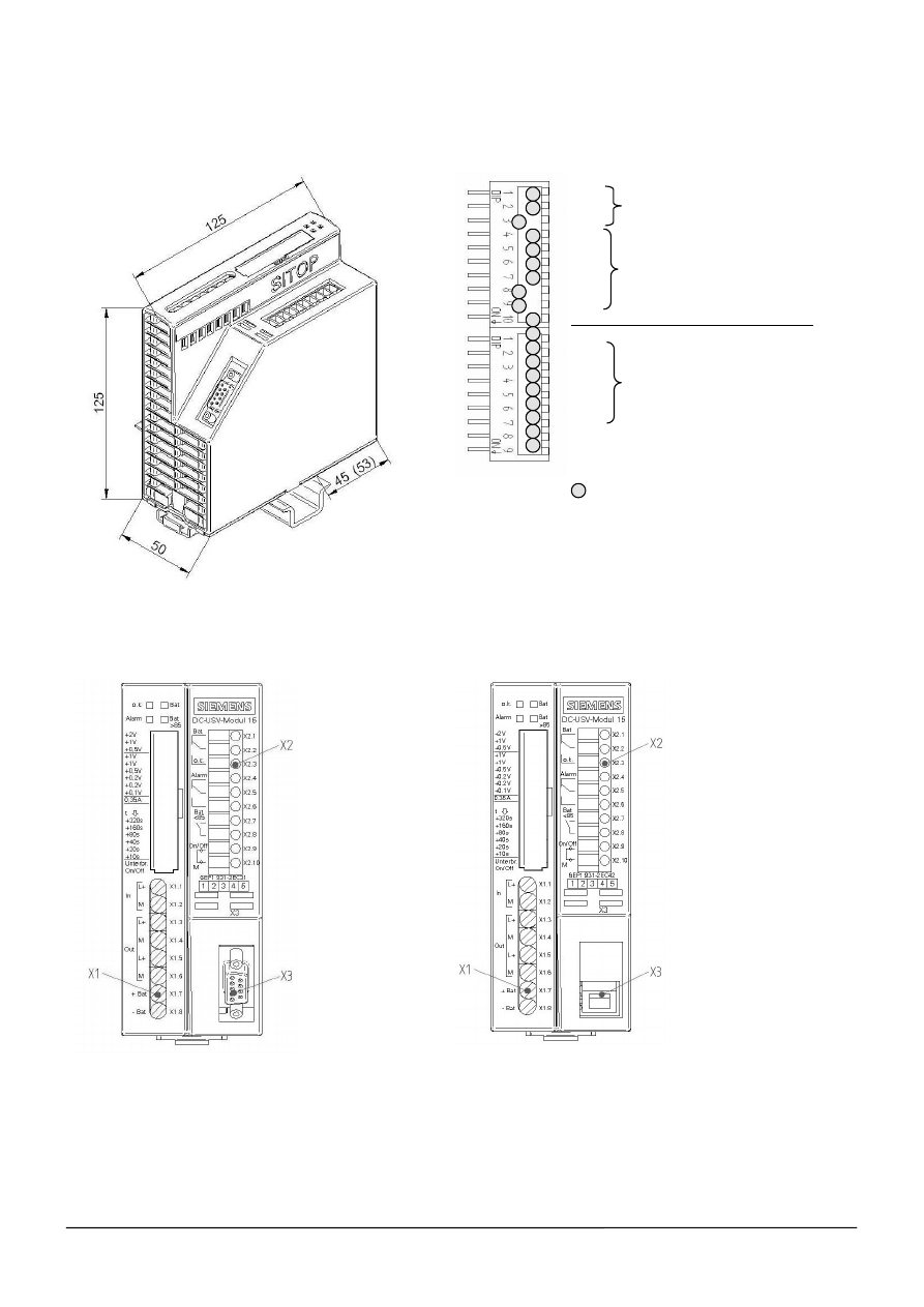
Maßbild
Dimension drawings
6EP1931-2EC21/31/42
On / Off
Die Hutschienenbefestigung auf der Rückwand kann von der Position wie SITOP modular (Auslieferzustand) durch Lösen der drei
selbstschneidenden Schrauben auf die Position wie SITOP power versetzt werden.
The mounting position on the rail can be changed from position SITOP modular (delivery state) to new position SITOP power (remove the
three self-tapping
screws)
Hinweis
Diese Betriebsanleitung enthält aus Gründen der Übersichtlichkeit nicht sämtliche Detailinformationen des Produkts und kann auch nicht jeden denkbaren Fall
der Aufstellung, des Betriebes oder der Instandhaltung berücksichtigen. Technische Änderungen jederzeit vorbehalten. In Zweifelsfällen gilt der deutsche
Text.
Note
These operating instructions do not purport to cover all details of the product, nor to provide for every possible contingency that may arise during installation,
operation or maintenance. Subject to change without notice. The German text applies in cases of doubt.
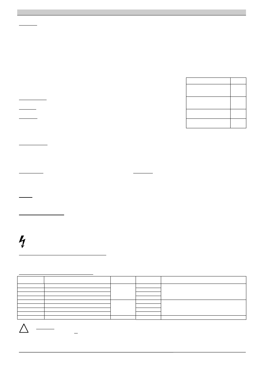
+2V Zuschaltschwelle
+1V (cut-in threshold)
+0,5V +22V fest eingestellt (fixed)
+1V
+1V
+0,5V Ladeschlussspannung
+0,2V (end-of-charge voltage)
+0,2V
+ 26,3V fest eingestellt (fixed)
+0,1V
0,35A / 0,7A Ladestrom (charging current)
eingestellte Zeit / max. Zeit (set time / max.)
+320s
+160s
+ 80s Pufferzeit (buffering time)
+ 40s
+ 20s
+ 10s +5s fest eingestellt (fixed)
Unterbrechung output (disconnection)
Betriebszustand Akku On / Off (operating
state battery)
Grundeinstellung, Auslieferzustand
(basic setting, delivery state)
Siemens AG Österreich, 07/2007
3
of 8
SITOP DC-USV-Modul 15
1
Deutsch
!
WARNHINWEISE
Nur entsprechend qualifiziertes Fachpersonal darf an diesem Gerät oder in dessen Nähe arbeiten.
Der einwandfreie und sichere Betrieb dieses Gerätes setzt sachgemäßen Transport, fachgerechte Lagerung, Aufstellung, Montage und die
ausschließliche Verwendung von SITOP Batteriemodulen (z.B. Batterie- bzw. Akku-Module 6EP1935-6MD11, 6EP1935-6MD31, 6EP1935-
6ME21oder 6EP1935-6MF01) voraus.
Der Wert des Ladestromes und der Ladeschlussspannung ist gemäß den Empfehlungen unter "Einstellungen" mit den DIP-Schaltern
anzupassen. Eine falsche Einstellung vermindert die Lebensdauer des Akkus und kann zu Zerstörungen führen.
ACHTUNG
Nur geschultes Personal darf das Gerät öffnen. Elektrostatisch gefährdete Bauelemente (EGB)
Beschreibung und Aufbau
Das DC-USV-Modul 15 ist ein Einbaugerät der SITOP -Reihe zur Montage auf Normprofilschiene DIN EN 50022-35x15/7,5. Für die Installation der Geräte und Batteriemodule sind die
einschlägigen DIN/VDE-Bestimmungen oder länderspezifischen Vorschriften (z.B. VDE 0510 Teil 2 / EN 50272-2) zu beachten .
In Kombination mit SITOP Batteriemodulen dient es zur Pufferung eines Teiles des Laststromes (max. 15A) von 24V-Laststromversorgungen der Reihe SITOP .
Der Eingang "Input L+" des DC-USV-Moduls ist mit dem Ausgang L+ des versorgenden 24V DC-Netzteils zu verbinden, der Eingang "Input M" mit dem Ausgang M des versorgenden Netzteils.
Das Batteriemodul wird an den Klemmen +Bat und –Bat angeschlossen. Die zu puffernden Verbraucher werden über den Ausgang „Output L+“ und „Output M“ des DC-USV-Moduls mit der am
Eingang angelegten Spannung
versorgt, bei Ausfall der 24V DC-Versorgungsspannung bzw. Spannungseinbruch unter die eingestellte Zuschaltschwelle werden die Verbraucher durch
Zuschaltung des im Bereitschaftsparallelbetrieb auf Vollladung gehaltenen Akku-Moduls versorgt.
Über DIP-Schalter können die Akku-Zuschaltschwelle, die Ladeschlussspannung, der Ladestrom und die Überbrückungszeit eingestellt werden. Ein Schalter dient zur Einstellung einer
definierten Überbrückungszeit mit anschließender Abschaltung des Akkus (siehe Einstellungen), ein Schalter zur Überbrückung des ON/OFF-Kreises, ein Schalter zur Wahl „vor Abschaltung der
Akkus U
a
für 5s unterbrechen“.
Vier Leuchtdioden, zwei potentialfreie Wechsler, ein Schließer und eine serielle Schnittstelle (nur 6EP1931-2EC31) bzw. USB-Schnittstelle (nur 6EP1931-2EC42) übernehmen die Signalisierung
von Betriebszuständen des DC-USV-Moduls 15 (siehe Signalisierung) und die Steuerung „Remote-Timerstart“.
Technische Daten
Eingangsgrößen:
Eingangsnennspannung: 24V DC
Arbeitsspannungsbereich: 22 bis 29V DC
max. Eingangsstrom bei 24V und Batterieladung: 16,0A DC
max. Eingangsstrom bei 24V und geladener Batterie: 15,1A DC
max. Batteriestrom im Pufferbetrieb: 15,1A DC
Ruhestromaufnahme aus dem Akku:
ca. 0,30 mA
Verlustleistung bei 24V und Batterieladung: ca. 16,0W
Verlustleistung 24V und geladener Batterie: ca. 14,0W
Verlustleistung im Pufferbetrieb: ca. 15,0W
Ausgangsgrößen:
Ausgangsnennspannung: U
A1
= 24V DC
Ausgangsnennstrom: I
A1
= 15A DC
Ausgangsstrombereich: I
A1
= 0 ... 15A DC
Ausgangskennlinie des Ladereglers:
Die Ladung des Akkumoduls erfolgt mit einstellbarem Konstantstrom bis zur
eingestellten Ladeschlussspannung.
Ladeschlussspannung: U
A2
= 26,3 bis 29,3V DC
Ladestrom: I
A2
= 0,35 oder 0,7A DC
Einstellungen
Einstellung der Zuschaltschwelle:
Sinkt die Eingangsspannung unter den eingestellten Wert der Zuschaltschwelle, so schaltet das USV-Modul in den Pufferbetrieb um. Die Verbraucher werden dann ausschließlich durch das
Akkumodul versorgt. Die Einstellung der Zuschaltschwelle erfolgt mittels 3 Stück DIP-Schalter (Position siehe Seite 2) gemäß Tabelle 2 (siehe Seite 7). Einstellbereich: 22,0 bis 25,5 V DC in 0,5V-
Schritten (Auslieferzustand: 22,5V DC
± 0,1V). Genauigkeit: ± 1,8%
Einstellung des Ladestromes:
Die Ladung des Akkumoduls erfolgt mittels Konstantstrom, bis die eingestellte Ladeschlussspannung erreicht ist. Der Ladevorgang wird dann beendet. Bei der Einstellung des Ladestromes sind die
Angaben des verwendeten Akkumoduls zu beachten, um die jeweils optimale Einstellung zu wählen. Die Einstellung des Ladestromes erfolgt mittels eines DIP-Schalters (Position siehe Seite 2).
Einstellbereich: 0,35A DC
± 0,1A DC oder 0,7A DC ± 0,1A DC (Auslieferzustand: 0,7A DC ± 0,1A DC)
Einstellung der Ladeschlussspannung:
Die Ladeschlussspannung hängt von der jeweiligen Type des Akkus sowie von der Temperatur welcher er ausgesetzt ist ab. Tabelle 1 (siehe Seite 7) beinhaltet die Ladeschlussspannungen für die
angegebenen Akkumodule bei unterschiedlichen Temperaturen. Zwischen den Werten kann interpoliert werden. Die Einstellung erfolgt mittels 6 Stück DIP-Schalter (Position siehe Seite 2) gemäß
Tabelle 3 (siehe Seite 7). Einstellbereich: 26,3 bis 29,3V DC in 0,1V-Schritten (Auslieferzustand: 26,6V DC
± 0,1V für +40°C Bleigelakku-Temperatur). Genauigkeit: ± 0,7%
Hinweis: Für vorteilhafte tiefere Temperaturen (Optimum sind +20 …+25°C) muss die Ladeschlussspannung auf Werte gemäß Tabelle 1 erhöht werden !
Einstellung des Betriebszustandes ON/OFF:
*
ACHTUNG: Zur normalen Funktion muss der Betriebszustand unbedingt auf „ON“ eingestellt werden (Auslieferzustand ist „OFF“), dazu DIP-Schalter auf „ON“ oder X2.9 mit X2.10 verbinden !!
Um eine unbeabsichtigte Entladung des Akkus (z.B. durch Ausschalten der Anlage) zu verhindern, kann das DC-USV-Modul mittels DIP-Schalter (oder durch Öffnen einer potenzialfreien
Verbindung oder Drahtbrücke zw. Klemme X2.9 und X2.10) in den Betriebszustand „OFF“ (Auslieferzustand) geschaltet werden.
Im Betriebszustand „ON“ (DIP-Schalter geschlossen oder Klemme X2.9 mit X2.10 mit potenzialfreiem Schließer für Umax = 15V DC, Imax = 10mA verbunden oder X2.9 auf Masse gelegt) bietet
das DC-USV-Modul die volle Funktionalität laut Spezifikation. Im Betriebszustand „OFF“ erfolgt bei Wegfall der Versorgungsspannung keine Umschaltung in den Pufferbetrieb. Alle anderen
Funktionen bleiben erhalten. Wird das USV-Modul während des Pufferbetriebes in den Zustand „OFF“ geschaltet, so wird auch der Pufferbetrieb beendet. Im Normalbetrieb wird die Einstellung
ON/OFF alle ca. 20s abgefragt.
Einstellung der Pufferzeit
Die Einstellung der Pufferzeit erfolgt mittels 6 Stück DIP-Schaltern (Position siehe Seite 2) und kann gemäß Tabelle 4 (siehe Seite 7) in 10s-Schritten von 5s bis 635s vorgenommen werden. Mit
Schalter 1 (eingestellte Zeit / max. Zeit) kann gewählt werden, ob die Beendigung des Pufferbetriebes nach der eingestellten Zeit oder erst bei Erreichen der Tiefentladeschwelle des Akkus (=
maximale Pufferzeit) erfolgt. (Auslieferzustand Pos. Off = maximale Pufferzeit). Bei 6EP1931-2EC31 und 6EP1931-2EC42 kann mit dem Remote-Signal (wird bei der Schnittstelle beschrieben)
der Puffertimer gestartet werden um die USV nach der eingestellten Pufferzeit abzuschalten. In diesem Fall muss der Schalter 1 (eingestellte Zeit / max. Zeit) auf Pos. Off stehen und der Schalter
Unterbrechung auf Pos. On. Wenn die Abschaltung erfolgt ist, besteht keine Möglichkeit mittels Änderung der Schaltereinstellung den Pufferbetrieb wieder einzuschalten. Erst nach Wiederkehr der
Eingangsspannung kann ein neuerlicher Pufferbetrieb erfolgen. Bei geladenem Batteriemodul Type 6EP1935-6MD11 (3,2Ah) und 10A Laststrom beträgt die Pufferzeit min. 4,5 Minuten bis zur
Entladung auf 20,4V DC.Bedingung: Neues Batteriemodul mit Akkutemperatur nicht unter +20°C
Unterbrechung der Ausgangsspannung
Mittels DIP-Schalter kann gewählt werden, ob die Ausgangsspannung nach Ablauf der eingestellten Pufferzeit für ca. 5 sec unterbrochen wird oder nicht (Auslieferzustand: Keine Unterbrechung).
Bei Einstellung „maximale Pufferzeit“ erfolgt eine Unterbrechung der Ausgangsspannung nur bei 6EP1931-2EC31 und 6EP1931-2EC42 über das Remote-Signal der Schnittstelle.
Schutz- und Überwachungsfunktionen
Verpolschutz:
Das USV-Modul ist gegen Verpolung der Eingangsspannung und des Akkus elektronisch geschützt.
Überstrom und Kurzschlussschutz
:
Im Normalbetrieb und im Pufferbetrieb ist das USV-Modul durch die interne Strombegrenzung (typ. 25 bis 40A für ca. 20ms bei Kurzschluss; 1,05
bis 1,4 I
N
für ca. 80ms bei Überstrom) geschützt. Eine eingebaute (nicht zugängliche) 16A - Sicherung schützt im Fehlerfall. . Im Normalfall erfolgen automatische Wiederanlaufversuche alle ca.
20s. Im Pufferbetrieb erfolgt speichernde Abschaltung. Wiederanlauf nach Rückkehr zum Normalbetrieb.
Tiefentladeschutz
:
Blei-Akkumulatoren dürfen nur bis zu einer bestimmten Spannung (Tiefentladeschwelle) entladen werden. Wird der Akku weiter entladen, so vermindert dies die
Lebensdauer und kann bis zur Zerstörung führen. Um den angeschlossenen Akku vor Beschädigung zu schützen, wird das USV-Modul speichernd abgeschaltet und die Verbraucher vom Akku
getrennt, sobald die Akkuspannung im Pufferbetrieb unter typ. 19V DC (Bereich 19,5...18,5V DC) sinkt.
Akkutest:
Um einen zuverlässigen Pufferbetrieb zu gewährleisten, muss sichergestellt werden, dass das Akku-Modul voll funktionsfähig ist. Aus diesem Grund wird im Normalbetrieb alle 4h das
angeschlossene Akku-Modul getestet. Der Test findet nur statt, wenn innerhalb dieser 4h kein Pufferbetrieb oder eine Abschaltung des USV-Moduls erfolgt ist. Falls in einer Anwendung in kürzeren
Intervallen regelmäßig ein Pufferbetrieb eingeleitet wird so erfolgt kein Akkutest. Ein
defekter Akku wird durch Blinken der Alarmmeldung signalisiert und muss ausgetauscht werden.
Wichtiger Hinweis zum Akkutausch:
Werden die Akkus bei blinkendem roten Alarm im laufenden Betrieb (d.h. ohne Abschaltung der 24V DC) ausgetauscht, erlischt der blinkende
rote Alarm (rote LED und Alarm-Relais) erst nach bis zu 4 Stunden ! Bei unzureichend geladenen neuen Akkus kann blinkender oder konstant roter Alarm (bei Akkuspannung < 18,5V) noch
länger (z.B. 8 oder 12 Stunden) anstehen !

Siemens AG Österreich, 07/2007
4
of 8
SITOP DC-USV-Modul 15
Deutsch
Signalisierung
„Normalbetrieb“,
d.h. die Eingangsspannung am DC-USV-Modul ist höher als die eingestellte Zuschaltschwelle. Die Verbraucher werden von der vorgeschalteten Stromversorgung versorgt.
Falls ein Akku-Modul angeschlossen ist, wird dieses geladen. Im Normalbetrieb leuchtet die grüne Leuchtdiode (o.k.) und der Relaiskontakt X2.2 – X2.3 (o.k.) ist geschlossen.
„>85% Vollladung“,
d.h. Akkuladung größer 85%
der je nach Alterung noch vorhandenen Restkapazität. Es leuchtet die zweite grüne Leuchtdiode (Bat>85%) und der Relaiskontakt X2.7
– X2.8 ist geschlossen. (zweite grüne Leuchtdiode aus und Relaiskontakt X2.7 – X2.8 offen (Ruhestellung bei abgeschaltetem Gerät) bedeutet : Bat<85%, d.h. Akkuladung unter 85%)
„Pufferbetrieb“,
d.h. die Eingangsspannung ist niedriger als die eingestellte Zuschaltschwelle. Die Verbraucher werden vom Akku-Modul versorgt. Im Pufferbetrieb leuchtet die gelbe
Leuchtdiode (Bat) und der Relaiskontakt X2.1 – X2.2 (Bat) ist geschlossen (Ruhestellung bei abgeschaltetem Gerät).
Alarmmeldung “Pufferbereitschaft fehlt“:
Bei Signal „Pufferbereitschaft fehlt“ leuchtet die rote Leuchtdiode (Alarm) und der Relaiskontakt X2.4 – X2.5 (Alarm) ist geschlossen
(Ruhestellung bei abgeschaltetem Gerät). Ursachen für eine fehlende Pufferbereitschaft im Normalbetrieb können sein:
Betriebszustand OFF, kein Akku-Modul angeschlossen, verpolter oder defekter Akku (Akkuspannung < 18,5V) oder Drahtbruch zwischen Akku und USV-Modul.
Die Abfrage von Betriebszustand ON/OFF, verpolter, defekter oder kein Akku sowie Drahtbruch und somit auch die Ausgabe des Signals erfolgt im Normalbetrieb alle 20s. Nach Fehlerende erfolgt
die Rücksetzung nach der nächsten Abfrage.
Blinkt das Signal im 2s Takt, so ist der Akku zwar defekt, jedoch kann ein Pufferbetrieb noch erfolgen. Die angegebenen Pufferzeiten können allerdings nicht mehr eingehalten werden. Das Akku-
Modul ist auszutauschen.
Im Pufferbetrieb bedeutet das Signal „Alarm“, dass die Akkuspannung auf <20,4V gesunken ist und eine Zwangsabschaltung zum Schutz des Akkus unmittelbar bevor steht. Nach Abschaltung des
Akkus aufgrund Überlast, Kurzschluss, Tiefentladeschutz oder abgelaufener Pufferzeit erlischt die rote Leuchtdiode (Alarm), der Relaiskontakt X2.4 – X2.5 bleibt geschlossen. Belastbarkeit der
Relaiskontakte: 60V DC / 1A oder 30V AC / 1A
Signal Klartext
Pufferbereitschaft vorhanden
Pufferbereitschaft fehlt
BUFRD
ALARM
Normalbetrieb
kein Normalbetrieb
DC_OK
DC_LO
kein Pufferbetrieb
Pufferbetrieb
*****
*BAT*
Serielle Schnittstelle:
Bei der Type 6EP1931-2EC31 werden die Signale zusätzlich über eine PC-fähige serielle Schnittstelle
ausgegeben. Die Signale werden mit einem jeweils 5 Zeichen langen String ausgegeben. Nachstehende Tabelle zeigt die Zuordnung. Bei
defektem Akku wechselt das Signal „Alarm/Pufferbereitschaft vorhanden“ mit einer Frequenz von 0,25Hz im Tastverhältnis 0,5. Ein
Softwaretool zum Auslesen und Verarbeiten der Signale steht im Internet unter http://www.ad.siemens.de/sitop kostenlos zur Verfügung.
Hier sind auch weitere Informationen zur Schnittstelle angeführt.
Technische Ausführung: 8N1 Senden und Empfangen, 9600 Baud, 8 Datenbit, 1 Stoppbit, kein Paritätsbit, Ausgabe der Signalzustände
alle 84ms
± 20%; 29ms ± 20% Datenausgabe; 55ms ± 20% Pause. Die PC-Schnittstelle muss eine sichere elektrische Trennung nach
EN 60950 aufweisen. Die Verbindung zum PC erfolgt über ein 1:1 durchverbundenes 9pol. SUB-D-Verlängerungskabel (Stecker/Buchse),
wobei nur 3 Pole benötigt werden. (Pin2, Pin3, Pin7).
Sendedaten: Pin2: RXD (Datenleitung, entspricht Pin3 bei 25-pol. Stecker/Buchse); Pin 3: TDX (negative Versorgung für Schnittstelle,
entspricht Pin2 bei einem 25-pol. Stecker/Buchse); Pin 7: RTS (positive Versorgung für Schnittstelle sowie gleichzeitig
Dateneingangsleitung für Remotesignal, entspricht Pin4 bei einem 25-pol. Stecker/Buchse).
Empfangsdaten: Pin7 (entspricht Pin4 bei einem 25-pol. Stecker/Buchse): Signal Remote Timerstart. Startet den Timer im DC-USV-Modul
mit der dort eingestellten Überbrückungszeit (Tabelle 2) (Nur bei Einstellung „maximale Zeitdauer“ und „Unterbrechung“). Nach der
eingestellten Überbrückungszeit wird der Pufferbetrieb beendet bzw. die Ausgangsspannung unterbrochen. Verlauf des erforderlichen
Remotesignals siehe Diagramm 1 (Seite 8), wird erzeugt durch Zu- und Abschalten der Versorgungsspannung.
≥ 85% Vollladung
≤ 85% Vollladung
BA>85
BA<85
USB:
Bei der Type 6EP1931-2EC42 werden die Signale zusätzlich über eine PC-fähige USB-Schnittstelle ausgegeben. Die Signale werden wie bei der seriellen Schnittstelle mit einem jeweils 5
Zeichen langen String ausgegeben. Es gilt die obenstehende Tabelle. Ein Softwaretool zum Auslesen und Verarbeiten der Signale steht im Internet unter http://www.ad.siemens.de/sitop kostenlos
zur Verfügung. Hier sind auch weitere Informationen zur Schnittstelle angeführt.
Technische Ausführung: Die USB Schnittstelle entspricht der Spezifikation 2.0. Die Kommunikation erfolgt aber nur mit Full Speed, d.h. 12Mbit/s, die USB-Optionsbaugruppe wird von der DC-USV
mit +5V versorgt („self powered“), Ausgabe der Signalzustände alle 75ms
± 20%; 29ms ± 20% Datenausgabe; 46ms ± 20% Pause. Die Verbindung zum PC erfolgt über ein handelsübliches 4-
adriges, geschirmtes USB-Kabel mit einem Wellenwiderstand von 90Ohm, einem USB Series „A“ Stecker zum PC und einem USB Series „B“ Stecker zur DC-USV und einer maximalen Länge von
5m. Das Kabel besteht aus zwei 28 bis 20 AWG „non-twisted“ USB-Versorgungsleitungen (VBUS und GND) und aus zwei 28 AWG „twisted pair“ Datenleitungen (D+ und D-).
Steckerbelegung: Pin 1: VBUS (+4,40V ... +5,25V DC), Sendedaten auf Pin2 (D-) und Pin 3 (D+), Pin 4: GND.
Empfangsdaten: Der Empfang des Zeichens „R“ (Signal Remote Timerstart) startet den Timer im DC-USV-Modul mit der dort eingestellten Überbrückungszeit (Tabelle 2) (Nur bei Einstellung
„maximale Zeitdauer“ und „Unterbrechung“). Nach der eingestellten Überbrückungszeit wird der Pufferbetrieb beendet bzw. die Ausgangsspannung unterbrochen.
Umgebung
Einsatzbedingungen nach EN 60721-3-3, Klimaklasse 3K3 (relative Luftfeuchte
5% bis 85% und absolute Luftfeuchte 1 g/m³ bis 25 g/m³; keine Betauung).
Ortsfester Einsatz, wettergeschützt, Verschmutzungsgrad 2
Temperatur für Lagerung und Transport: -40 bis +70°C
Temperatur für Betrieb: 0 bis +60°C
Gewicht
6EP1931-2EC21 0,4kg
6EP1931-2EC31/42 0,45kg
Vorschriften
Schutzart: IP20 nach EN60529 (VDE 0470 Teil1)
Schutzklasse III nach EN60950
VDE 0100 Teil 410 (IEC 364-4-41)
VDE 0106 Teil 1 (IEC 536)
VDE 0113 Teil 1 (EN 60204-1)
IEC 61131; ; UL 508 / CSA C22.2 File E197259
Funkentstört nach EN55022, Grenzwertkurve B
Störfestigkeit nach EN 61000-6-2
Montagehinweise
Das Gerät ist zwecks ordnungsgemäßer Entwärmung vertikal so zu montieren, dass die Eingangsklemmen, die Ausgangsklemmen und Zuluftschlitze unten sind. Unterhalb und oberhalb des
Gerätes soll mindestens ein Freiraum von je 50mm eingehalten werden.
Um Störeinkopplungen und thermische Beanspruchung zu minimieren, sollen DC-USV-Module und zugehörige Batteriemodule mindestens 50 cm entfernt von Kommutierungsdrosseln installiert
werden! Schnittstellen- (serielle SS, USB) und Steuerleitungen (ON/OFF-Steuerstromkreis) dürfen nicht direkt parallel zu Leistungsleitungen (insbesondere Leitungen zwischen Frequenzumrichter
und Motor sowie Frequenzumrichter und Kommutierungsdrossel) verlegt werden. Um Störeinkopplungen zu minimieren soll zu diesen Leitungen ein Abstand von mindestens 10cm eingehalten
werden. Batteriemodule sollen niederohmig verdrahtet (4mm²) und an kühlem Ort installiert werden (bei Schaltschränken in der Regel ganz unten).
Montage / Demontage siehe Bild Seite 8.
Vor Beginn der Installations oder Instandhaltungsarbeiten ist der Hauptschalter der Anlage auszuschalten und gegen Wiedereinschalten zu sichern. Es ist
die Betriebsanleitung von SITOP power zu beachten.
Die Sicherung am Akku-Modul ist bei allen Arbeiten zu entfernen.
Wartungshinweise für Batteriemodule
Um für Bleigel-Batteriemodule eine möglichst lange Lebensdauer zu erhalten empfiehlt sich technologiebedingt, die Batteriemodule bei der Erst-Inbetriebnahme der Anlage mehrmals auf ca. 19V
zu entladen und wieder aufzuladen (ca. 3 x Entladen / Laden, z.B. mit den 24V DC-Verbrauchern der Anlage entladen, hierzu Pufferzeit auf max. Zeit einstellen. Wiederaufladen durch das DC-
USV-Modul). Bei Reinblei-Batteriemodulen ist das nicht erforderlich.
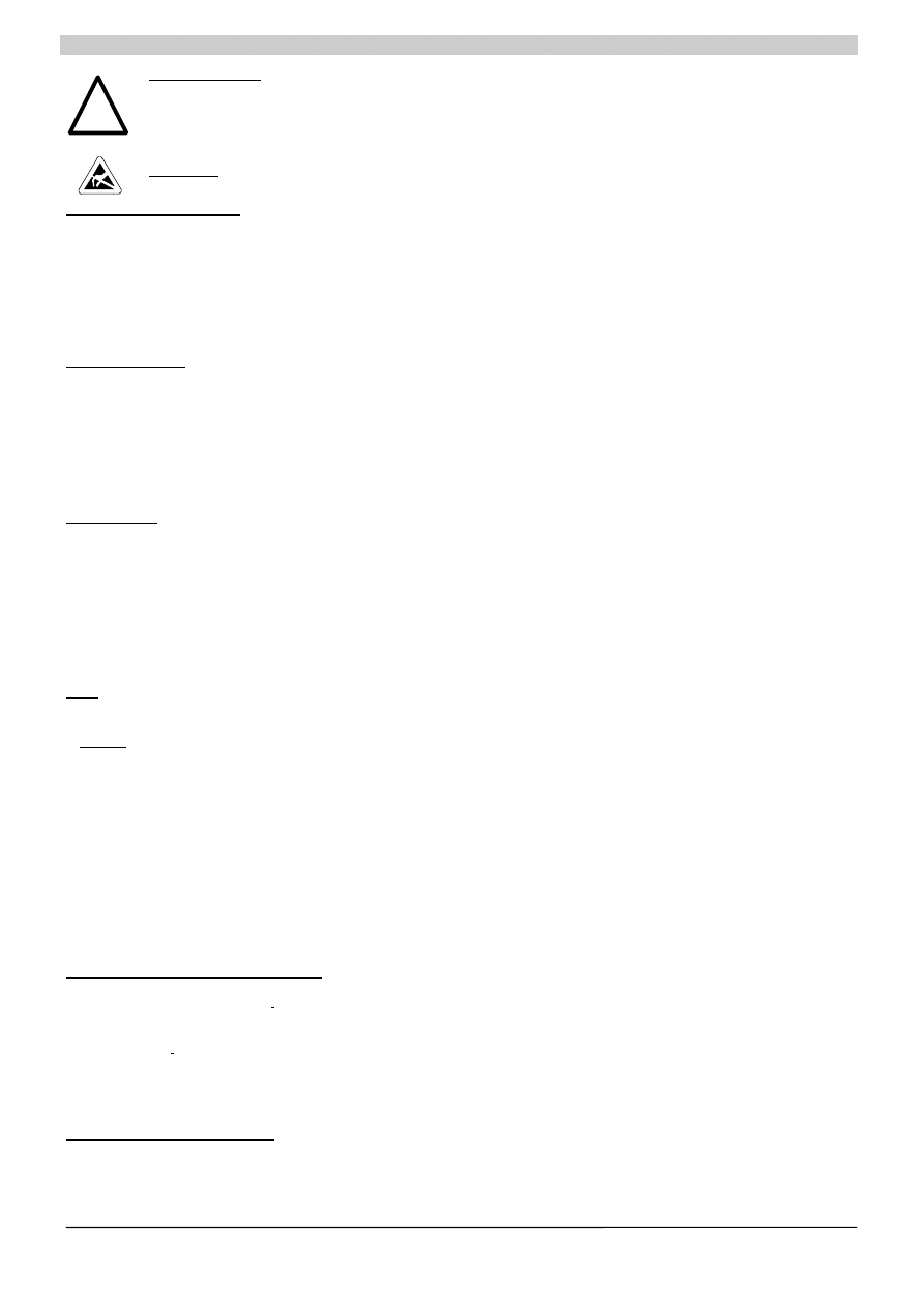
Anschluss und Klemmenbelegung
Klemmen Funktion
Anschlusswert Anschlusslänge
Bemerkung
X1.1
Eingangsspannung DC 24V
1,0 ... 4mm
2
bis 3m
Schraubklemmen für Schraubendreher mit
X1.3, X1.5
Ausgangsspannung DC 24V
17...11 AWG
4,5mm Klingenbreite
X1.2/X1.4, X1.6
Ein/Ausgangsspannung DC 0V
X1.7/X1.8
Akku-Modul DC 24V
bis 3m
empfohlenes Anzugsmoment 0,7-0,9Nm
X2.1,2,3
Signal: Normalbetrieb / Pufferbetrieb
0,5... 2,5mm
2
bis 3m
Schraubklemmen für Schraubendreher mit
X2.4,5,6 Signal:
Pufferbereitschaft fehlt / vorhanden
20...13 AWG
bis 3m
3,5mm Klingenbreite
X2.7,8
Signal: Ladezustand >85%
bis 3m
X2.9/X2.10
On/Off – Brücke (keine Brücke =Off)
bis 3m
empfohlenes Anzugsmoment 0,5-0,7Nm
X3
Serielle Schnittstelle bzw. USB-Schnittstelle
Siehe Beschreibung oben
!
ACHTUNG
Die externe Beschaltung aller Klemmen (auch Signal- und Meldekontakte) muss den Anforderungen an SELV-Kreise nach
VDE 0805 / EN 60950 genügen.
Siemens AG Österreich, 07/2007
5
of 8
SITOP DC-USV-Modul 15
English
!
WARNINGS
Only properly qualified personnel may work on or around this equipment.
The successful and safe operation of this equipment is dependent on proper handling, storage and installation. Correct functioning is also
dependent on the use of SITOP battery modules (e.g. battery modules of type 6EP1935-6MD11, 6EP1935-6MD31, 6EP1935-6ME21or 6EP1935-
6MF01.
The charging current level and the end-of-charge voltage must be adjusted with DIP-switches to the settings recommended under "Technical
Data". Setting incorrect current and voltage values reduces the life of the battery and may cause irreparable battery damage.
CAUTION
Only trained personnel may open the unit. Electrostatically sensitive devices (ESD)
Description and Design
The DC-UPS module 15 is a chassis unit in the SITOP power product range for mounting on a DIN rail of type DIN EN 50022-35x15/7.5.
The modules and the battery modules must be installed in accordance with the applicable DIN/VDE specifications or pertinent regulations in the country of installation (e.g. VDE 0510 Part2 / EN
50272-2).
In conjunction with the battery module, it buffers a proportion of the load current (max. 6A) of 24V load current supplies in the SITOP range.
Input "Input L+" on the DC-UPS module must be connected to output L+ of the 24V DC power supply unit and input "Input M" to output M of the power supply unit. The battery module is connected
to terminals +Bat and –Bat.
The loads to be buffered are supplied via outputs "Output L+" and "Output M" on the DC-UPS module with the voltage connected to the input. If the 24V DC supply
voltage fails or drops below the set cut-in threshold, the battery module, which is maintained at full charge in continuous supply mode, is connected in to supply the loads.
The battery cut-in threshold, end-of-charge voltage, charging current and the buffering time can be set via DIP-switches. A switch is provided for setting a defined buffering (stored energy) time with
subsequent disconnection of the battery (see Settings).
The operating states of the DC-UPS module 6 are signaled by four LEDs, two floating changeover and one normally-open contacts and a serial interface (6EP1931-2EC31 only) or USB-interface
(6EP1931-2EC42 only) (see Signaling) and the control signal “Remote Timerstart”.
Technical Data
Input quantities:
Rated input voltage: 24V DC
Operating voltage range: 22 to 29V DC
Max. input current at 24V and battery charging: 16.0A DC
Max. input current at 24V and charged battery: 15.1A DC
Battery current in floating operation: 15.1A DC
Max. quiescent current consumption of the battery appr. 0.3mA
Power loss at 24V and battery charging: appr. 16.0W
Power loss at 24V and charged battery: appr. 14.0W
Power loss in floating operation: appr. 15.0W
Output quantities:
Rated output DC voltage: V
A1
= 24V DC
Rated output direct current: I
A1
= 15A DC
Output current range: I
A1
= 0 … 15A DC
Output characteristic of charging regulator:
The battery module is charged at an adjustable constant current until the
set end-of-charge voltage is reached.
End-of-charge voltage: V
A2
= 26.3 to 29.3V DC
Charging current: I
A2
= 0.35 or 0.7A DC
Settings
Setting the cut-in threshold:
If the input voltage drops below the selected cut-in threshold voltage, the UPS module switches over to floating operation. The loads are then supplied solely by the battery module. The cut-in
threshold is set via three DIP-switches (see page 2 for position) according to table 2 (see page 7).
Setting range: 22.0 to 25.5V DC in 0.5-steps (delivery state: 22.5V DC
± 0.1V), accuracy ± 1.8%
Setting the charging current:
The end-of-charge voltage depends on the battery type and on the battery`s ambient operating temperature. Table 1 (see page 7) shows the end-of-charge voltages for specific battery modules at
different temperatures. It is possible to interpolate between these values. The voltage is set by six DIP-switches (see page 2 for position) according to table 3 (see page 7).
Setting range: 26.3 to 29.2V DC in 0.1V-steps (delivery state: 26,6V DC
± 0.1V for +40°C lead-gel-battery temperature), accuracy ± 0.7%V DC
Note: for lower temperatures (recommended optimum temperature +20°C ... +25°C) increase the end-of-charge voltage according to table 1 !
Setting the end-of-charge voltage:
The end-of-charge voltage depends on the battery type and on the battery´s ambient operating temperature. Table 1 (see page 7) shows the end-of-charge voltages for specific battery modules at
different temperatures. It is possible to interpolate between these values. The voltage is set by six DIP-switches (see page 2 for position) according to table 3
(see page 7).
Setting range: 26.3 to 29.2V DC in 0.1V-steps (delivery state: 27.0V DC
± 0.1V for +25°C lead-gel-battery temperature), accuracy ± 0.7%
Setting the operating state ON/OFF:
*
Caution: For normal operation "ON" state is necessary (delivery state is “OFF”), in order to achieve that use DIP-switch closed or terminals X2.8 and X2.9 connected with X2.10
To prevent the battery from being discharged unintentionally (e.g. when the system power is disconnected), the DC-UPS module can be switched with a DIP-switch (or a wire jumper (or floating
connection) inserted between terminals X2.9 and X2.10) to operating state "OFF" (delivery state). In the "ON" state (DIP-switch closed or terminals X2.8 and X2.9 connected with a floating
normally-open contact (V
max
= 15V DC, I
max
= 10mA) ), the DC-UPS module is fully functional according to specification. In the "OFF" state, the module does not switch over to floating operation
when the mains supply is disconnected but remains functional in every other respect. If the module is switched to "OFF" in floating operation, it stops operating in floating mode.
During normal operation, the polling interval for the ON/OFF setting is appr. 20s.
Setting the buffering time:
The buffering time is set via six DIP-switches (see page 2 for position) as illustrated in Table 4 (see page 7) in 10s-steps from 5s to 635s. By switch 1 (delivery state max. time) you can choose
whether floating operation will be terminated after a prespecified period or when the exhaustive discharge threshold of the battery (= maximum buffering time) is reached (delivery state: max.
buffering time). Using a 6EP1931-2EC31 or 6EP1931-2EC42 the remote signal starts the timer to terminate after a prespecified period (switch 1 has to be in position Off and switch interruption in
position On). Once the battery has been disconnected, there is no way in which floating operation can be restarted again by altering the switch setting. Only when the input voltage has recovered
floating operation can be resumed. The buffering time is a minimum of 10 minutes until discharge to 20.4V DC with a charged battery module type 6EP1935-6MD11 (3.2Ah) and a load current of
5A. (requires a new battery modul with a temperature of the battery above +20°C)
Interruption of the output voltage:
By a DIP-switch you can choose if the output voltage is interrupted for 5 s at the end of the buffering time or not (delivery state : no interruption). Using a 6EP1931-2EC31 or 6EP1931-2EC42 and
set “max. time” an interruption is started by the remote signal.
Protective and Monitoring Functions
Reverse polarity protection:
The UPS module is electronically protected against polarity reversal of the input voltage and battery.
Overcurrent and short-circuit protection:
The UPS module is protected by an internal current limitation (typ. 25 to 40A for appr. 20
ms at a short-circuit,
1.05 to 1.4 I
N
for appr. 80ms at a overcurrent) in normal and floating operations. An internal 16A-fuse (not accessible) protects the module in case of failure. In normal operation automatic restart
attempts are made appr. every 20s. In floating operations the module shuts down in store mode. Restart after return to normal operation.
Exhaustive discharge protection:
Lead-acid batteries may only be discharged down to a certain voltage (exhaustive discharge threshold). Allowing them to discharge further will
reduce their service life and may result in irreparable battery damage. In order to protect the battery against damage, the UPS module is shut down in store mode and the loads disconnected from
the battery as soon as the battery voltage drops below typ. 19V DC (range 19.5 to 18.5V DC) in floating operation.
Battery test:
In order to guarantee reliable floating operation, the battery module must be checked to ensure that it is fully functional. For this reason, the connected battery module is tested
every 4 hours under normal operation. The test is carried out only if the battery has not operated in floating mode or been disconnected within this 4 hour period. The battery test is not performed for
applications in which floating operation is activated regularly at shorter intervals. A defective battery is signaled by a flashing alarm and must be replaced then.
Important note changing rechargeable batteries:
if you change rechargeable batteries with red alarm blinking under current operation (i.e. without switching off 24V DC), red
blinking alarm (red LED and alarm relay) turns off only up to 4 hours ! When exchanging to not completely charged batteries the blinking or constantly occurent alarm (when battery voltage <
18,5V) may persist even longer (e.g. 8 or 12h !).
Siemens AG Österreich, 07/2007
6
of 8
SITOP DC-USV-Modul 15
English
Signaling
"Normal operation",
i.e. the input voltage at the DC-UPS module is higher than the set cut-in threshold. The loads are being supplied by the line-side power supply. If a battery module is
connected, it is fully charged. In normal operation, the green LED (o.k.) is illuminated and relay contact X2.2 – X2.3 (o.k.) is closed.
“>85% charge”, i.e. battery is loaded more than 85% (available rest capacity dependent upon aging). The second green LED (Bat>85%) is illuminated and relay contact X2.7 – X2.8 is closed. .
(second green LED off and relay contact X2.7 – X2.8 open (de-energized position when unit is disconnected) means : Bat<85%, i.e. battery charge below 85%)
"Floating operation",
i.e. the input voltage is lower than the set cut-in threshold. The loads are being supplied by the battery module. In floating operation, the yellow LED (Bat) is illuminated
and relay contact X2.1 – X2.2 (Bat) closed (de-energized position when unit is disconnected).
Alarm signal "Battery not ready":
When the "Battery not ready" signal is active, the red LED (Alarm) is illuminated and relay contact X2.4 – X2.5 (Alarm) closed (de-energized position when
unit is disconnected). Causes for the "battery not ready" state in normal operation are as follows: "OFF" operating state, no battery module connected, reversed polarity or defective battery (battery
voltage < 18.5V) or open circuit between battery and UPS module. The interval for polling the operating states ON/OFF, reversed polariy, defective battery or no battery module connected, open
circuit between battery and UPS module, and for activating the relevant signal output is 20 s during normal operation. After the end of the failure the signal remains till to the next polling.
If the signal flashes in a 2s cycle, this indicates that the battery is defective, but still capable of floating operation. The specified buffering times cannot be kept in such cases. The battery module
must be replaced.
The "Alarm" signal in floating operation means that the battery voltage has dropped to <20.4V and automatic disconnection to protect the battery is imminent. When the battery has been
disconnected due to overload, short circuit, exhaustive discharge protection or buffering timeout, the red LED (Alarm) goes out, but relay contact X2.4 – X2.5 remains closed. Load rating of relay
contacts: 60V DC / 1A or 30V AC / 1A
Signal
Text
Battery ready
Battery not ready
BUFRD
ALARM
Normal operation
Not normal operation
DC_OK
DC_LO
Not floating operation
Floating operation
*****
*BAT*
Interface
:
With module type 6EP1931-2EC31, the signals are additionally outputs via a PC-capable serial interface. They are each
displayed in the shape of 5 characters of plain text. The assignment is shown in the table on the right. When the battery is defective, the
signal "Battery ready / not ready" is displayed alternately in a 0.25Hz cycle with a duty cycle of 0.5. A tool for reading out and processing
the signals is available free of charge on the Internet at http://www.ad.siemens.de/sitop. This website also contains further information
about the interface.
Technical specification: 8N1 transmit and receiving, 9600 baud, 8 data bits, 1 stop bit, no parity bit, signal state output every 84ms
± 20%;
data output 29ms
± 20%, pause 55ms ± 20%.PC-interface has to be safety separated according to EN 60950. The connection to the PC is
made by means of a continuous 9-way SUB-D extension lead, (plug/socket), although only 3 pins are needed. (Pin2, Pin3, Pin7)
Transmit data: Pin2: RXD (data line, acc. to Pin3 of a 25-way plug/socket); Pin3: TDX (neg. supply for the interface, acc. to Pin2 of a 25-
way plug/socket); Pin7: RTS (pos. supply for the interface and at the same time data input line for the remote signal, acc. to Pin4 of a 25-
way plug/socket).
Receiving data: Pin7 (acc. to Pin4 of a 25-way plug/socket): Signal Remote Timerstart. The timer of the UPS module is started with the set
buffering time (table 2) (only with setting “max. time” and “disconnection”). After the set buffering time the floating operation ends or the
output voltage will be disconnected. Sequence of the necessary remote signal see diagram1 (page 8), generated by On and Off of the
supply voltage.
>85% charge
<85% charge
BA>85
BA<85
USB:
With module type 6EP1931-2EC42, the signals are output additionally via a PC-capable USB interface. They are each displayed in the shape of 5 characters of plain text. The assignment is
shown in the table above. A tool for reading out and processing the signals is available free of charge on the Internet at http://www.ad.siemens.de/sitop. This website also contains further
information about the interface.
Technical specification: The USB interface is according to specification 2.0, the communication runs only with full speed, i.e. 12Mbit/s. The Interface will be supplied by the DC-UPS with +5V (“self-
powered”), signal state output every 75ms
± 20%; data output 29ms ± 20%, pause 46ms ± 20%. The connection to the PC is made by means of a usual 4-wired shielded USB-cable with a wave-
resistance of 90Ohm, a USB Series”A” connector to the PC and a USB Series “B” connector to the DC-UPS module and a maximum length of 5m. The cable contains two 28 to 20 AWG “non-
twisted” USB-supply wires (VBUS and GND) and two 28 AWG “twisted pair” data wires (D+ and D-).
Pin assignment: Pin1: VBUS (+4.4V to +5.25V DC), transmit data on Pin2 (D-) and Pin3 (D+), Pin4: GND
Receiving data: Receive of the character “R” (Signal Remote Timerstart) starts the timer of the DC-UPS module with the set buffering time (table 2) (only with setting “max. time” and
“disconnection”). After the set buffering time the floating operation ends or the output voltage will be disconnected.
Environment
Operating conditions acc. to EN 60721-3-3, climate model 3K3 (relative air
humidity 5% to 85%, absolute air humidity 1 g/m
3
to 25 g/m
3
, no condensation)
Stationary operation, weather protected, pollution degree 2
Temperature for storage and shipment: -40 to +70°C
Temperature for operation: 0 to +60°C
Weight
6EP1931-2EC21 0.4kg
6EP1931-2EC31/42 0.45kg
Standards
Degree of protection: IP20 to EN60529 (VDE 0470 Part1)
Protection class III to EN60950
VDE 0100 Part 410 (IEC 364-4-41)
VDE 0106 Part 1 (IEC 536)
VDE 0113 Part 1 (EN 60204-1)
IEC 1131; UL 508 / CSA C22.2 File E197259
RI suppression to EN55022, limit-value curve B
Interference immunity to EN 50082-2 incl. Table A2,A3
Installation Instructions
In order to guarantee effective cooling, the unit must be vertically installed such that the input and output terminals and the incoming air slots are at the bottom. A clearance of at least 50 mm must
be left above and below the unit. Assembly / disassembly see page 8.
To reduce EMI and thermal strain DC-UPS modules and their battery modules should be installed at least 50cm away from commutating chokes ! Interfaces (serial, USB) and control leads
(ON/OFF control circuit) must not be laid directly in parallel to power leads or cables (especially leads between frequency converter and motor or frequency converter and commutating choke).
To minimize EMI the distance to those leads should be at least 10cm. Battery modules should be connected low-resistively (4 mm
2
) and in a cool place (in cubicles usually at the lower end).
Before commencing with the installation or any repair work, switch off the plant main switch and lock it in the "OFF" position. Please read the operating
instructions for SITOP power.
The fuse on the battery module must be removed before any work is carried out.
Maintenance Instructions for Battery modules
To maintain the life cycle of lead gel accumulators as long as possible, it is recommended to discharge them several times down to appr. 19V and then re-charge them (approx. 3 times discharge /
charge, discharge for instance by the DC loads of the plant, buffer time set to maximum; re-charge by DC-UPS module) at the first start-up of the machine.
With pure lead battery modules this is not necessary.
Connection and Terminal Assignments
Terminals Function
Cable
cross-
section
Cable length
Comments
X1.1
Input voltage DC 24V
1.0 ... 4mm
2
up to 2m
Screw-type terminals for screwdriver with
X1.3, X1.5
Output voltage DC 24V
17...11 AWG
4.5mm blade width
X1.2/X1.4, X1.6
Input/output voltage DC 0V
X1.7/X1.8
Battery module DC 24V
up to 2.5m
Recommended tightening torque 0.7-0.9Nm
X2.1,2,3
Signal: Normal operation / Floating operation
0.5... 2.5mm
2
up to 3m
Screw-type terminals for screwdriver with
X2.4,5,6
Signal: Battery not ready / ready
20...13 AWG
up to 3m
3.5mm blade width
X2.7,8
Signal: charge >85%
X2.9/X2.10
On/Off jumper (no jumper =Off)
up to 3m
Recommended tightening torque 0.5-0.7Nm
X3
Serial interface or USB-interface
See description above
!
CAUTION
The external circuitry of all terminals (including signaling and status contacts) must meet the safety requirements stipulated by
VDE 0805 (EN 60950): SELV.
Siemens AG Österreich, 07/2007
7
of 8
SITOP DC-USV-Modul 15
Tabelle 1: Ladeschlussspannungen bei anderen Akku-Temperaturen
Table 1: End-of-charge voltage for other battery temperatures
Akkumodule Typ Bleigel /Battery type lead gel: 6EP1935-6MC01, 6EP1935-6MD11, 6EP1935-6ME21, 6EP1935-6MF01
-10°C
29,0V
0°C
28,4V
10°C
27,8V
20°C
27,3V
25°C
27,0V
30°C
26,8V
35°C
26,7V
40°C
26,6V
Akkumodul Typ Reinblei /Battery type pure lead : 6EP1935-6MD31D31
-10°C
29,0V
0°C
28,6V
10°C
28,3V
20°C
27,9V
25°C
27,7V
30°C
27,5V
35°C
27,4V
40°C
27,2V
45°C
27,0V
50°C
26,8V
60°C
26,4V
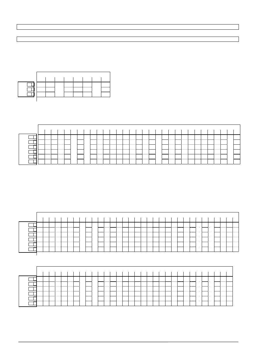
Tabelle 2: Einstellbare Zuschaltschwellen
Table 2: Adjustable cut-in threshold
gewünschte Zuschaltschwelle [V]
22,0 22,5 23,0 23,5 24,0 24,5 25,0 25,5
0 0 0 0 1 1 1 1
0 0 1 1 0 0 1 1
0 1 0 1 0 1 0 1
On
←1
2
3
Tabelle 3: Einstellbare Ladeschlussspannungen
Table 3: Adjustable end-of-charge voltage
gewünschte Ladeschlussspannung [V]
26,3 26,4 26,5 26,6 26,7 26,8 26,9 27,0 27,1 27,2 27,3 27,4 27,5 27,6 27,7 27,8 27,9 28,0 28,1 28,2 28,3 28,4 28,5 28,6 28,7 28,8 28,9 29,0 29,1 29,2 29,3
0 0 0 0 0 0 0 0 0 0 0 0 0 0 0 0 0 0 0 0 1 1 1 1 1 1 1 1 1 1 1
0 0 0 0 0 0 0 0 0 0 1 1 1 1 1 1 1 1 1 1 1 1 1 1 1 1 1 1 1 1 1
0 0 0 0 0 1 1 1 1 1 0 0 0 0 0 1 1 1 1 1 0 0 0 0 0 1 1 1 1 1 1
0 0 0 0 1 0 0 0 0 1 0 0 0 0 1 0 0 0 0 1 0 0 0 0 1 0 0 0 0 1 1
0 0 1 1 1 0 0 1 1 1 0 0 1 1 1 0 0 1 1 1 0 0 1 1 1 0 0 1 1 1 1
On
←4
5
6
7
8
9
0 1 0 1 0 0 1 0 1 0 0 1 0 1 0 0 1 0 1 0 0 1 0 1 0 0 1 0 1 0 1
Tabelle 4: Einstellbare Pufferzeiten
Table 4: Adjustable buffering time
Schalterstellung / Switch position: On = 1 ; Off = 0
Schalter 1 auf Pos. On: Einstellung um nach der gewünschten Pufferzeit abzuschalten (setting to terminate after the prespecified buffering time)
Schalter 1 auf Pos. Off: Die Abschaltung erfolgt erst bei Erreichen der Tiefentladeschwelle des Akkus. Bei 6EP1931-2DC31 und 6EP1931-2DC42 kann im Remote-
Betrieb nach der eingestellten Pufferzeit die Spannung unterbrochen werden ( DIP-Schalter Unterbrechung – On)
Setting to terminate when the exhaustive discharge threshold of the battery is reached. Using a 6EP1931-2EC31 or 6EP1931-2EC42 an interruption is started by the
remote signal. (DIP-switch Disconnection – On)
gewünschte Pufferzeit / buffering time [s]
5 15 25 35 45 55 65 75 85 95 105
115 125 135 145 155 165 175 185 195 205 215 225 235
245
255
265
275
285 295 305 315
0 0 0 0 0 0 0 0 0 0 0 0 0 0 0 0 0 0 0 0 0 0 0 0 0 0 0 0 0 0 0 0
0 0 0 0 0 0 0 0 0 0 0 0 0 0 0 0 1 1 1 1 1 1 1 1 1 1 1 1 1 1 1 1
0 0 0 0 0 0 0 0 1 1 1 1 1 1 1 1 0 0 0 0 0 0 0 0 1 1 1 1 1 1 1 1
0 0 0 0 1 1 1 1 0 0 0 0 1 1 1 1 0 0 0 0 1 1 1 1 0 0 0 0 1 1 1 1
0 0 1 1 0 0 1 1 0 0 1 1 0 0 1 1 0 0 1 1 0 0 1 1 0 0 1 1 0 0 1 1
0 1 0 1 0 1 0 1 0 1 0 1 0 1 0 1 0 1 0 1 0 1 0 1 0 1 0 1 0 1 0 1
On
←2
3
4
5
6
7
gewünschte Pufferzeit / buffering time [s]
325 335 345 355 365 375 385 395 405 415 425 435 445 455 465 475 485 495 505 515 525 535 545 555 565 575 585 595 605 615 625 635
1 1 1 1 1 1 1 1 1 1 1 1 1 1 1 1 1 1 1 1 1 1 1 1 1 1 1 1 1 1 1 1
0 0 0 0 0 0 0 0 0 0 0 0 0 0 0 0 1 1 1 1 1 1 1 1 1 1 1 1 1 1 1 1
0 0 0 0 0 0 0 0 1 1 1 1 1 1 1 1 0 0 0 0 0 0 0 0 1 1 1 1 1 1 1 1
0 0 0 0 1 1 1 1 0 0 0 0 1 1 1 1 0 0 0 0 1 1 1 1 0 0 0 0 1 1 1 1
0 0 1 1 0 0 1 1 0 0 1 1 0 0 1 1 0 0 1 1 0 0 1 1 0 0 1 1 0 0 1 1
On
←2
3
4
5
6
7
0 1 0 1 0 1 0 1 0 1 0 1 0 1 0 1 0 1 0 1 0 1 0 1 0 1 0 1 0 1 0 1
Siemens AG Österreich, 07/2007
8
of 8
SITOP DC-USV-Modul 15
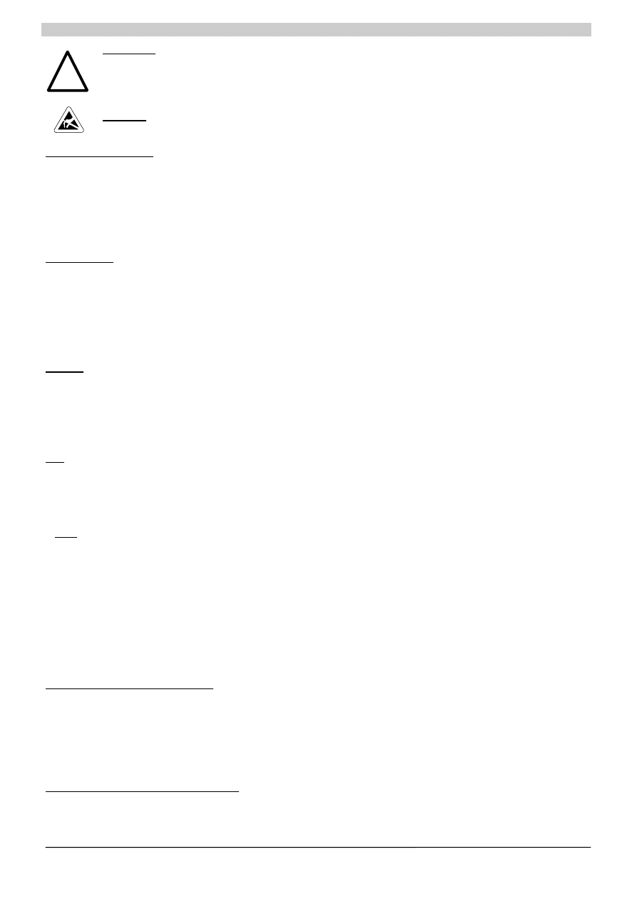
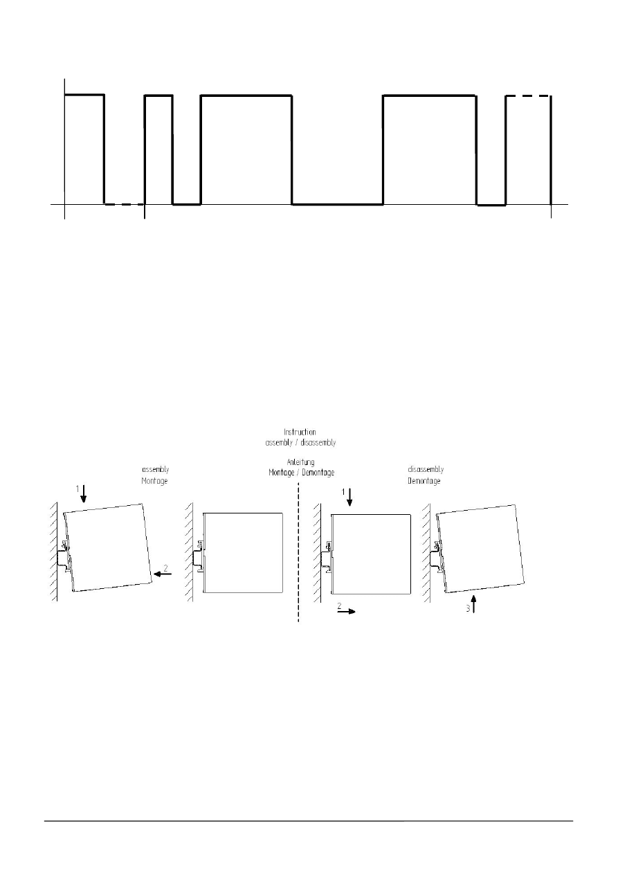
Diagramm 1: Remote-signal
Diagram 1: Remote-signal
Lowsignal unbestimmter Länge startet das Remotesignal
Low signal with undefined length starts the remote signal
1.) 30ms – 120ms Highsignal
2.) 30ms – 120ms Lowsignal
3.) 200ms – 400ms Highsignal
4.) 200ms – 400ms Lowsignal
5.) 200ms – 400ms Highsignal
6.) 30ms – 120ms Lowsignal
7.) max. 256s Highsignal
mit der letzten Flanke High-Low wird das Remote-Signal ausgewertet und der Timer gestartet
the remote signal will be evaluated with the last High-Low edge and starts the timer
Herausgegeben vom / Published by
SIMEA
Bereich / Group A&D
Siemensstrasse
88-92
© Siemens AG Österreich All rights reserved.
A
1210
Wien
Liefermöglichkeiten
und
technische
Änderungen
vorbehalten
Delivery
conditions
and
technical
content
subject
to
changes
H
L
1 2 3 4 5 6 7 t
Wyszukiwarka
Podobne podstrony:
opi sitop dc ups 40 07 2007 ende
opi sitop dc ups 40 07 2007 ende
opi sitop dc ups 6 07 2007 ende
mod części 15 07
Podstawy woiągów i kanalizacji 15.11.2007, STUDIA, Polibuda - semestr IV, Podstawy Woiągów i Kanaliz
testy egzaminacyjne z anatomii, egzaminypraktyczne 2006 2007, Bydgoszcz, dnia 15 maja 2007 roku
kodeks karny skarbowy 15 07 2016
PIP zmiany i uprawnienia od 1[1] 07 2007
15 07 86
CREN SGH 15 KU 2007
wyklad 6 15.11.2007, Administracja UŁ, Administracja I rok, Teoria organizacji i zarządzania, Teoria
loveparade 2010 anlage 16 protokoll 15 07 10
kk, ART 191 KK, WYROK SA W KATOWICACH z dnia 15 lutego 2007 r
opzzata skarbowa stan na 26 07 2007
Szczęśliwa Dziesiątka Disco Polo (15 07 2010)
PWiK - Wykład 15-10-2007, Budownictwo S1, Semestr IV, PWiK, Wykłady, PWiK 2
więcej podobnych podstron