Bulletin 783
I
Cleaning Flame Ionization Detectors: When and How
Noisy chromatograms, random spikes, and poor detector
sensitivity are symptoms of a dirty FID — a common
problem in gas chromatography. You will consistently
obtain better chromatograms and reduce instrument down-
time if you keep the FID clean. This bulletin describes
methods of troubleshooting noise to confirm whether the
source is a dirty FID, methods of cleaning FIDs, and ways to
reduce contamination in the future.
Key Words:
●
gas chromatograph maintenance
●
flame ionization
●
detector maintenance
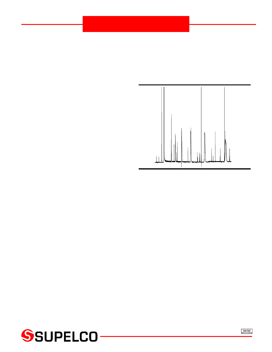
The most common source of contamination in a flame ionization
detector (FID) is bleed from silicone stationary phases and silylating
reagents, which combust in the FID and produce silica. When
deposited on surfaces within the detector, this white powder
causes noisy chromatograms, random spikes, and poor detector
sensitivity (Figure A). The use of carbon disulfide or hydrocarbons
as solvents creates other forms of detector contamination.
Is the Detector Really Your Problem?
Before you shut down your instrument and clean your detector,
it is wise to confirm that the problem is detector-related, rather
than related to some other component of your system. The few,
simple procedures described here can eliminate other possibilities
as the source of the problem.
Carrier Gas and Stationary Phase
Seal the detector inlet in the oven with a Swagelok
®
plug and
ignite the detector. If the chromatogram noise disappears, then
the source of the problem is contaminants in the carrier gas or
bleed from the chromatography column, not a dirty FID. To
prevent this problem, you should always use a carrier gas purifi-
cation system and columns prepared from chromatography-
quality stationary phases.
Hydrogen and Air Systems
A problem in the hydrogen or compressed air delivery system can
be a source of noise. Measure the flow rates for both gases (refer
to your instrument manual). An incorrect flow rate in either source
can cause noise, lack of sensitivity, and/or difficulty when igniting
the flame. Also check the connections on both systems. An
electronic gas leak detector, such as one of the GOW-MAC
®
detectors from Supelco, will quickly and easily pinpoint gas leaks
via differences in thermal conductivity. If you do not find a major
leak, check the gas pressure at the cylinders. If the pressure is less
than 500psig, replace the cylinder.
Figure A.
A Noisy Chromatogram,
Caused by a Dirty FID
A contaminated cylinder of gas could be the source of the
problem, especially if the noise appeared several hours after you
changed a cylinder. Check each cylinder for contaminants and
replace if necessary. To eliminate the problem of contaminated
air, we recommend using a zero air generator (see page 3).
Electrical System
Electrical noise can cause symptoms similar to a dirty FID. A poor
connection due to oxidized contacts will act as a small capacitor
and cause spikes and/or loss of sensitivity. If your FID has clip
contacts to the collector or flame jet, we recommend you clean
them periodically with emery cloth.
Electrical devices located near your chromatograph can interfere
with the instrument’s power supply and cause intermittent or
random spikes. To isolate this source of noise, disconnect the
electrometer cable(s) from the FID. If noise persists, it is coming
from the electrical system.
In a two-detector system, electrical noise will appear on both
detectors. If noise is present on only one channel, the electrom-
eter or electrometer cable(s) may be the problem. Switch the
cables at the electrometer and FID. If the noise now appears on
the channel that was previously noise-free, replace the cable
supplying the noise. If the noise does not change channels, check
the electrometer on the malfunctioning channel by removing the
electrometer cable at the FID, resting the cable connector on a
surface to prevent contact with the metal frame of the GC. If the
noise continues, the electrometer should be serviced. If the noise
is eliminated, examine the hydrogen and oxidant systems.
796-0593
T100783
I
©
1998 Sigma-Aldrich Co
.

SUPELCO
Bulletin 783
2
Before Cleaning
Before you disassemble the detector, we suggest you take the
following precautions:
•
Think Safety ! Disconnect the power to the detector, and be
sure the collector assembly is cool before you begin.
•
Be Prepared ! Have spare detector parts available, as rec-
ommended in your instrument manual. Some detectors
contain ceramic parts which break easily; and spare parts
can minimize downtime should breakage occur.
•
Pay Attention ! Carefully note the distance from the collec-
tor assembly to the flame jet. On some detectors this
distance is not fixed, and if you inadvertently alter the
distance when you reassemble the detector, you can dras-
tically change the FID response. The flame may be difficult
to ignite and noise can occur.
How to Clean an FID
To properly clean an FID, you must clean the collector assembly,
the jets, the Teflon
®
or ceramic insulators, and the housing. If the
detector has been cleaned recently, a light coat of silica or a single
silica flake could be causing the trouble, and only a light cleaning
is required. If the detector has not been cleaned recently, a
thorough cleaning probably is necessary.
Light Cleaning
There are two ways of removing light coatings of dirt. Both
methods are simple and should be attempted before costly
instrument downtime is incurred.
Freon
®
TF Injection: A light coat of silica can be removed by
injecting several microliters of Freon TF (Detector Cleaner No. 1,
see Ordering Information) into the column while the detector is
lit. The Freon is combusted by the flame, producing hydrofluoric
acid (HF). The HF converts the silica to a volatile fluoride, cleaning
the detector in the process. Freon TF acts best when used on a
regular basis, to prevent the buildup of silica, rather than as a cure
for a very dirty detector.
Scrubbing: Disassemble the detector and scrub the contamina-
tion from the components. The brass wire brushes in our detector
cleaning kits (see Ordering Information) will not scratch metal or
ceramic parts; use a nylon brush on Teflon parts.
1. Disconnect the power to the detector, and be sure the
collector assembly is cool.
2. Remove the collector assembly and brush the collector to
remove the deposits.
3. Clean the jets, including the bore, using a brass toothbrush
and a fine wire, such as a syringe needle cleaning wire.
4. Clean the electrical contacts, using a fine emery cloth. (Be
careful not to bend the contacts.)
Thorough Cleaning
If the light cleaning methods do not adequately clean your FID,
a more thorough cleaning is required. Disconnect the power to
the detector, allow the detector to cool, then disassemble it.
1.
Fill the basin in an ultrasonic cleaning device with a detergent
that will effectively remove silica and other contamination
from the FID (e.g., a 10:1 water solution of Detector Cleaner
No. 2, a surfactant which is especially effective in removing
heavy deposits of silica). Immerse the FID parts, except the
electrical contacts, and sonicate for 2 hours. You can brush
the collector assembly and jets (with nylon or brass brushes)
with the cleaning solution during the ultrasonic treatment.
After the treatment, rinse the parts with distilled water to
remove the detergent, then rinse with acetone to remove the
water. Use a fine emery cloth to clean the electrical contacts.
2.
Ceramic parts of an FID are best cleaned with aqua regia, a
1:~3 mixture of concentrated nitric and hydrochloric acids,
at ambient or mildly elevated temperature. Before treat-
ment, remove all metal and rubber from the ceramic parts –
aqua regia will attack these. Place the ceramic parts in a
beaker half-filled with aqua regia for one hour, then rinse
with water and acetone as in step 1.
Exercise extreme caution – aqua regia is extremely corrosive.
3.
After you have cleaned all parts of the detector, check all O-
rings and replace them if necessary. Worn-out O-rings will
cause gas leaks, which can produce detector noise or an
increase in detector contamination.
Reassemble the FID, light the flame, and allow the detector
temperature to equilibrate at 10°C–50°C higher than the column
will reach during typical operation. This will reduce the amount
of phase condensing onto the detector parts. Do not exceed the
maximum temperature limit of the stationary phase – many
columns fit far enough into the detector to expose the phase to
these elevated temperatures. Set the proper flow rates for
hydrogen and compressed air (refer to the instrument manual),
and ignite the flame. Turn on the electrometer and allow a few
minutes for warmup. The flame should now be stable and
noise-free.
Reducing Detector Noise
and Contamination
Conditioning
Most detector noise and contamination is the result of column
bleed. The amount of bleed is greatest when the column is initially
conditioned. Your detector will remain clean longer if you condi-
tion a new column before connecting it to the detector. By-
products eluted during conditioning, potentially harmful to the
FID, are voided into the oven.
Connect the column inlet to the injector as usual. Place a restrictor
at the column exit to prevent back diffusion of air into the column
(exposure of a heated column to air can destroy the liquid phase).
Purge the column with carrier gas at room temperature for a few
hours before you begin the temperature program. Do not allow
a combustible carrier gas such as hydrogen, methane, etc. to exit
the column into the oven. Pipe these materials out of the oven and
into a hood. (Be sure to attach a restrictor to the outlet of the
pipeline in the hood.) Consult the column manufacturer for
conditioning details, i.e., duration and temperature of condition-
ing. Do not routinely condition new columns at the maximum
temperature limit of the stationary phase – this will reduce column
life.
Connecting a well-conditioned column to a clean FID should
produce good sensitivity. If detector stability quickly degener-
ates, you should evaluate the quality of your stationary phase and
carrier gas.
Stationary Phase
Use GC quality stationary phases whenever possible — they are
purified to remove lower molecular weight components. Techni-
cal grade materials will bleed more than GC quality materials.
3
SUPELCO
Bulletin 783
Carrier Gas
Moisture and oxygen in the carrier gas will cause stationary phase
to deteriorate and bleed. Use chromatography-quality gases, and
periodically monitor the gas system for leaks, which might allow
atmospheric oxygen and water to enter the column. For details
on carrier gas purification, ask for Bulletin 848 and Bulletin 918.
Septa
Frequently check the septum for leaks. A leaking septum can allow
oxygen and water to enter the carrier gas and cause the stationary
phase to deteriorate and bleed. To check for leaks without
contaminating the septum (and subsequent samples) with liquid
leak detectors, use an electronic GOW-MAC leak detector (see
Ordering Information. If you run your instrument frequently, we
recommend you change the septum daily. If you change the
septum at the end of the work day you can condition the new
septum overnight. For septa-related information and trouble-
shooting hints, request Application Note 82.
Ordering Information:
Reduce total hydrocarbons to less than 0.1ppm, stabilizing
baselines and improving detection
CE approved – UL and CSA listed – IEC 1010 certified
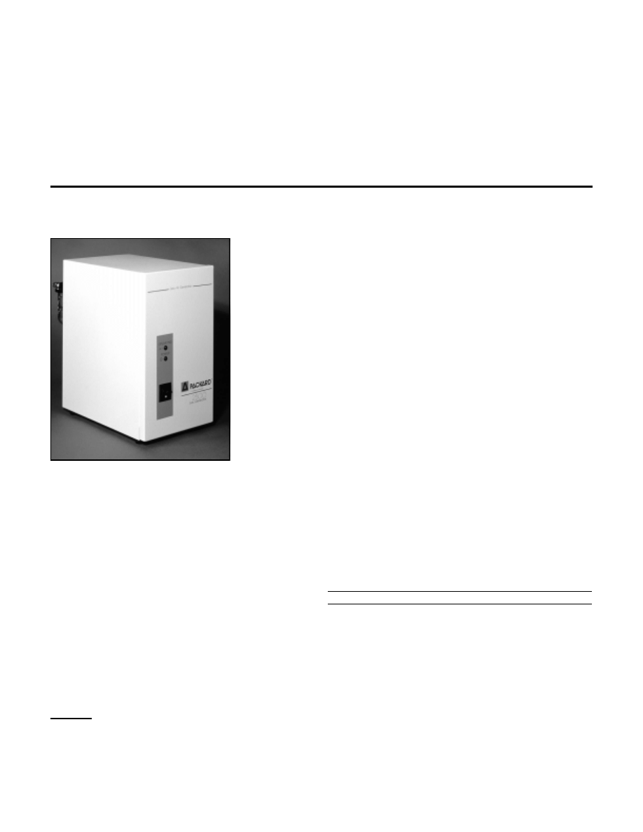
These Packard zero air generators produce ultra-high purity
(UHP) air from a standard compressed air supply – at continuous
flow rates up to 3500cc/min, at pressures up to 125psig. We
recommend using a zero air generator with flame ionization
detectors – the resulting noise reduction and improved baseline
stability allow lower detection limits, increasing the sensitivity of
your analyses.
The Packard system consists of three stages: a 0.5µm coalescing
inlet filter removes particles, oil, and water, a heated catalyst
removes hydrocarbons, and a 0.01µm cellulose fiber outlet filter
removes residual particulate material from the product air stream.
Maintenance is minimal – just clean the inlet and outlet filters
every 6 months and change them every 2 years. For replacement
filters, refer to our catalog.
994-0071
Packard Zero Air Generators
Specifications
Product Purity:
< 0.1ppm total hydrocarbons
(as methane)
Inlet Air Pressure:
2-125psig
Delivery Pressure:
125psig
Outlet:
1/8" Swagelok
Pressure Drop at
Maximum Flow Rate:
5psig
Flow Rate Pressure
Stabilization Time:
<2 minutes
Maximum Air Flow Rate:
Models 1000, 1001
1000cc/min (serves 2-3 FIDs)
Models 3500, 3501
3500cc/min (serves 10 FIDs)
Dimensions:
Models 1000, 1001
25 x 14.7 x 30.8cm (H x W x D)
Models 3500, 3501
29.2 x 17.8 x 39.4cm
Weight:
Models 1000, 1001
11lbs/5kg
Models 3500, 3501
20lbs/9.1kg
Electrical Requirements
Models 1000, 3500 (110 VAC)
100-125VAC, 60Hz, 100W, 1.0A (1.5A fuse)
Models 1001, 3500 (220VAC)
200-250VAC, 50 Hz, 100W, 0.5A (0.8A fuse)
One-Year Parts and Labor Warranty from Packard.
Description
Cat. No.
Packard Zero Air Generators
Model 1000 (110VAC)
22824
Model 3500 (110VAC)
27625-U
Model 1001 (220VAC)
22830-U
Model 3501 (220VAC)
27626-U
Activated Charcoal Trap
If halocarbons or sulfur-containing compounds might be present
in the source air, we recommend using a Supelpure-HC trap to
avoid contaminating the catalyst in the zero air generator.
Supelpure-HC Trap
1/8" fittings
22445-U
1/4" fittings
22446
Replacement Charcoal, 400cc
22451
Trademarks
Freon, Teflon – E.I. du Pont de Nemours & Co., Inc.
GOW-MAC — GOW-MAC Instrument Co.
Snoop – Nupro Company
Supelco – Sigma-Aldrich Co.
Swagelok – Crawford Fitting Co.
SUPELCO
Bulletin 783
4
BULLETIN 783
BOD
Molecular Sieve 5A Water Vapor Traps
These traps effi-
ciently remove
water and heavy
h y d r o c a r b o n s
from com-
pressed air, elec-
trolytically pro-
duced hydrogen, house nitrogen, or other gases with high
moisture or hydrocarbon content. 200cc traps are 2' x 1" (61 x
2.5cm), 750cc traps are 18" x 2 3/8" (45.7 x 6cm). The extended
bed length ensures prolonged contact between the gas and the
adsorbent. Use the smaller tubes with up to 5 GCs, the larger traps
with 6-20 instruments.
Molecular Sieve 5A Water Vapor Traps
200cc, 1/8" Fittings
20619
200cc, 1/4" Fittings
20618
750cc, 1/4" Fittings
23991
750cc, 1/2" Fittings
23992
S-Trap, 1/8" Fittings
503118
Molecular Sieve 5A Refill, 1/2lb./0.22kg
20298
Mounting Clip for 200cc Traps
503231
Mounting Clip for 750cc Traps
24983
Mounting Clip for S-Trap
502901
E000008
Description
Cat. No.
Detector Cleaner No. 1
Detector Cleaner No. 1, a halocarbon liquid (Freon TF), cleans
your FID in place. Just inject a few microliters into a column that
is connected to the lighted detector. The combustion products of
the cleaner remove silica deposits from the detector electrodes.
Recommended for preventive cleaning. In liquid form, Detector
Cleaner No. 1 is useful for removing greases and oils from
glassware, syringes, etc.
Detector Cleaner No. 1, 100mL
33000-U
Detector Cleaner No. 2
For removing heavy silica deposits. Immerse silica-coated detec-
tor parts in a 1:10 mixture of this surfactant cleaning solution in
water, preferably in an ultrasonic bath. The concentrate is an
innocuous aqueous solution.
Detector Cleaner No. 2, 100mL
22662
Detector
Cleaning Kit
Consists of two
brass wire brushes,
a brass tube brush
for your specific in-
jection port, a brass
toothbrush, and a
piece of fine emery
cloth.
Needle and Jet
Cleaning Kit
10 wires, each in 5
diameters, plus sy-
ringe cleaning solu-
tion.
Needle Cleaning Kit
21578
Description
Cat. No.
910-0031
910-0030
For Hewlett-Packard Models
(collector
@ 0.145" ID)
22403
For Perkin Elmer Sigma Series Models
(collector
@ 0.187" ID)
22405
For Varian Models
(collector
@ 0.235" ID)
22404
995-0110
Mini Model 21-050
Deluxe Model 21-250
GOW-MAC Gas Leak Detectors
GOW-MAC Gas Leak Detectors pinpoint leaks by detecting gases
that have a thermal conductivity value different from that of air.
This clean, efficient method of leak detection completely elimi-
nates the risk of system contamination that can result from using
soap solution. These easy-to-use units feature probes designed to
reach difficult and confined locations. In the deluxe model, an
audible tone alerts you to a leak. An LED bar graph on the hand-
held mini model visually alerts you to leaks.
Deluxe Model 21-250
22409
Mini Model 21-050
110VAC/60Hz
22807
220VAC/50Hz
22808
Carrying Case for Mini Model
22809
For more information, or current prices, contact your nearest Supelco subsidiary listed below. To obtain further contact information, visit our website (www.sigma-aldrich.com), see the Supelco catalog, or contact
Supelco, Bellefonte, PA 16823-0048 USA.
ARGENTINA
· Sigma-Aldrich de Argentina, S.A. · Buenos Aires 1119
AUSTRALIA
· Sigma-Aldrich Pty. Ltd. · Castle Hill NSW 2154
AUSTRIA
· Sigma-Aldrich Handels GmbH · A-1110 Wien
BELGIUM
· Sigma-Aldrich N.V./S.A. · B-2880 Bornem
BRAZIL
· Sigma-Aldrich Quimica Brasil Ltda. · 01239-010 São Paulo, SP
CANADA
· Sigma-Aldrich Canada, Ltd. · 2149 Winston Park Dr., Oakville, ON L6H 6J8
CZECH REPUBLIC
· Sigma-Aldrich s.r.o.· 186 00 Praha 8
DENMARK
· Sigma-Aldrich Denmark A/S · DK-2665 Vallensbaek Strand
FINLAND
· Sigma-Aldrich Finland/YA-Kemia Oy · FIN-00700 Helsinki
FRANCE
· Sigma-Aldrich Chimie · 38297 Saint-Quentin-Fallavier Cedex
GERMANY
· Sigma-Aldrich Chemie GmbH · D-82041 Deisenhofen
GREECE
· Sigma-Aldrich (o.m.) Ltd. · Ilioupoli 16346, Athens
HUNGARY
· Sigma-Aldrich Kft. · H-1067 Budapest I
NDIA
· Sigma-Aldrich Co. · Bangalore 560 048
IRELAND
· Sigma-Aldrich Ireland Ltd. · Dublin 24
ISRAEL
· Sigma Israel Chemicals Ltd. · Rehovot 76100
ITALY
· Sigma-Aldrich s.r.l. · 20151 Milano
JAPAN
· Sigma-Aldrich Japan K.K. · Chuo-ku, Tokyo 103
KOREA
· Sigma-Aldrich Korea · Seoul
MALAYSIA
· Sigma-Aldrich (M) Sdn. Bhd. · Selangor
MEXICO
· Sigma-Aldrich Química S.A. de C.V. · 50200 Toluca
NETHERLANDS
· Sigma-Aldrich Chemie BV · 3330 AA Zwijndrecht
NORWAY
· Sigma-Aldrich Norway · Torshov · N-0401 Oslo
POLAND
· Sigma-Aldrich Sp. z o.o. · 61-663 Poznañ
PORTUGAL
· Sigma-Aldrich Quimica, S.A. · Sintra 2710
RUSSIA
· Sigma-Aldrich Russia · Moscow 103062
SINGAPORE
· Sigma-Aldrich Pte. Ltd.
SOUTH AFRICA
· Sigma-Aldrich (pty) Ltd. · Jet Park 1459
SPAIN
· Sigma-Aldrich Quimica, S.A. · 28100 Alcobendas, Madrid
SWEDEN
· Sigma-Aldrich Sweden AB · 135 70 Stockholm
SWITZERLAND
· Supelco · CH-9471 Buchs
UNITED KINGDOM
· Sigma-Aldrich Company Ltd. · Poole, Dorset BH12 4QH
UNITED STATES
· Supelco · Supelco Park · Bellefonte, PA 16823-0048 · Phone 800-247-6628 or 814-359-3441 · Fax 800-447-3044 or 814-359-3044 · email:supelco@sial.com
H
Supelco is a member of the Sigma-Aldrich family. Supelco products are sold through Sigma-Aldrich, Inc. Sigma-Aldrich warrants that its products conform to the information contained in this and other
Sigma-Aldrich publications. Purchaser must determine the suitability of the product for a particular use. Additional terms and conditions may apply. Please see the reverse side of the invoice or packing slip.
Wyszukiwarka
Podobne podstrony:
ECU codes and how to read them out
MCRP 3 37C Flame, Riot Contol Agents and Herbicide Ops
„The Blame Game” and how it affects our lives
10 killer job interview questions and how to answer them
The crime of bad Power Point and how to avoid it
Compressors And How To Use Them
When I consider how mu light is spent
101 Project Management Problems and How to Solve Them 2011
Jack M Bickham 38 Most Common Fiction Writing Mistakes and how to avoid them
ECU codes and how to read them out
Bearden Electret What it is and how it works (2005)
Your Forces and How to Use Them Christian D Larson
Hacking Basic Security, Penetration Testing and How to Hack (2015)
Collaborative Defense Against Zero Day and Polymorphic Worms Detection, Response and an Evaluation F
Weber; Philosophy of Science, 2001 Determinism, Realism, And Probability In Evolutionary Theory Th
Secrets and How to Keep Them
MICHAŁ MOCHOCKI Reality is Broken Why Games Make Us Better and How They Can Change the World Jane M
13 Creativity and how to foster it
Online Investors What They Want, What They Do, and How Their Portfolios Perform
więcej podobnych podstron