

2
Abstract
KNX is an ideal candidate for large commercial sector projects due to its flexibility, high
reliability and complete interworking between products. However, the massive scale
difference between even the largest residential installations and modern commercial sites
means that there are a number of obstacles facing the implementation of large KNX projects
in practice. Over the past few years, Andromeda have tackled these problems by
implementing subtly different EIB design strategies and by working closely with a number of
KNX manufacturers. Where necessary we have developed our own products to fulfil the
specialised requirements of particularly large projects.
Andromeda have adopted an IP based EIB network structure in which line and area couplers
are no longer used. This has allowed EIB networks to extend across previously unattainable
distances and also made it possible to route a high volume of data to head-end computers
where it is processed for maintenance and operational management purposes.
In addition, through in-depth collaboration with Andromeda, manufacturers have
implemented new and exciting features and products to support our cutting edge projects.
These developments include:
•
KNX – DALI gateway, with support for
-
Self contained emergency lighting testing
-
Central battery emergency lighting testing
-
Local circuit failure
-
Simplified DALI commissioning
-
Simplified DALI maintenance
•
KNX – IP gateway, with support for
-
De-centralised scheduling, with ability to be modified over IP
-
Advanced Scene Control
•
Switch Actuator with luminaire failure detection
We have also implemented advanced system functionality, including :
•
Virtual energy metering
•
Lamp run hour metering
•
Device failure monitoring
The complexity of large projects, coupled with the possibility of human error makes the
traditional ETS project design and commissioning cycle unattractive and a lengthy process.
We have therefore had to develop new and exciting ways of automating the system design &
configuration. The projects typically have small commissioning windows, requiring multiple
teams to work concurrently on the same project. This again has lead to innovation in the
control and management of ETS databases and to the custom development of our own
commissioning tools.

3
Table of Contents
Abstract .................................................................................................... 2
Table of Contents....................................................................................... 3
1
Large Project Design Strategies............................................................ 4
1.1
Physical Project Structure.............................................................. 4
1.1.1
The Traditional approach........................................................ 4
1.1.2
Advantages of EIBNet/IP ........................................................ 4
1.1.3
A Cheaper and Easier Topology .............................................. 5
1.2
Logical Project Structure ............................................................... 6
1.2.1
Group Addresses Limitations................................................... 6
1.2.2
Re-use of Group Addresses..................................................... 6
1.2.3
Shortfall of Group Address Re-use........................................... 8
2
KNX Product Advancement................................................................... 9
2.1
Driving Factors for Large Projects .................................................. 9
2.2
Special KNX-DALI gateway enhancements.................................... 10
2.3
Special KNX - IP Gateway Enhancements. .................................... 11
3
Commissioning and Maintenance........................................................ 12
3.1
Multiple Users Working Concurrently............................................ 12
3.1.1
Subdivision of Large Projects ................................................ 12
3.1.2
Maintaining Control with a “Master” Spreadsheet ................... 12
3.2
High Skill Levels Required For Commissioning and Maintenance .... 13
3.2.1
DALI Commissioning and Maintenance .................................. 14
3.3
Proactive Maintenance ................................................................ 15
4
Suggested ETS Improvements ........................................................... 16
4.1
Concurrent Access through XML Data Export/Import..................... 16
4.2
Version Control........................................................................... 16
4.3
Access Control............................................................................ 17
4
1 Large Project Design Strategies
1.1 Physical Project Structure
1.1.1 The Traditional approach
Traditional KNX architecture allows for 15 areas of 15 lines to be connected using
conventional line and area couplers. While in theory this allows for the creation of very large
KNX projects, in practice the main and backbone lines tend to get easily overloaded. This
especially becomes an issue when a head end PC is connected to the system, as all group
addresses that need to be visualised have to be routed on to the backbone line.
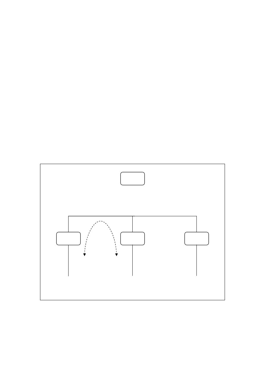
1.1.2 Advantages of EIBNet/IP
The introduction of EIBNet/IP has changed the way large projects can be approached. It is
no longer necessary to worry about the mainline becoming overloaded as Ethernet is over
1000 times faster. In particular the differentiation between
routing
and
tunnelling
/
object
server
communication the EIBNet/IP protocol further supports this approach. This is
illustrated in
Figure 1
and
Figure 2
.
Figure 1 EIBNet/IP Routing
KNX/IP
Gateway
KNX/IP
Gateway
KNX/IP
Gateway
KNX Line
KNX Line
KNX Line
All routed group addresses are broadcast to all KNX/IP gateways. However, only group addresses that are
specifically required in other KNX lines need to be routed. In practice this is a small set of group addresses, e.g.
global commands, time, date, etc
Head End
PC
5
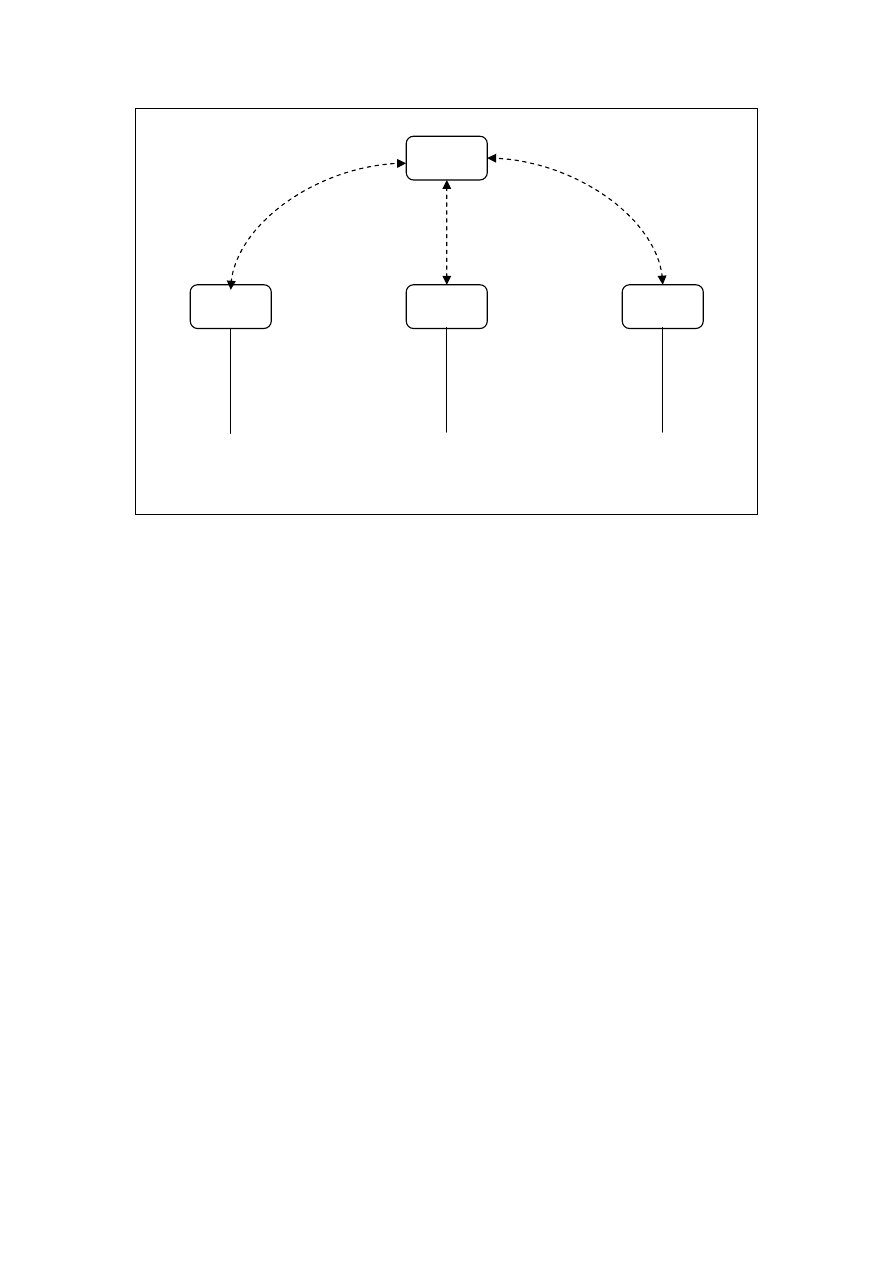
Figure 2 EIBNet/IP Tunnelling / Object Server
1.1.3 A Cheaper and Easier Topology
The increased bandwidth associated with EIBNet/IP Routing along with the absence of any
restrictions on the main line current consumption when KNX/IP gateways are used in place of
traditional KNX line couplers makes it possible to implement a flat topology, rather than the
usual two-tier line/area topology. Area couplers are therefore no longer required. This has the
advantage of reducing cost and simplifying the physical installation (which on large projects is
usually performed by untrained workers with little understanding of the importance of
differentiating between three different types of green cable that are otherwise identical).
The resulting topology is illustrated in Figure 3 .
KNX/IP
Gateway
KNX/IP
Gateway
KNX/IP
Gateway
KNX Line
KNX Line
KNX Line
Head End
PC
Head End PC creates a point-to-point connection with each KNX/IP gateway. Group address information is
transferred directly to/from the particular KNX line without affecting any other KNX line. This allows for massive
data transfer between the head end and the system as a whole without overloading any particular KNX line.
6
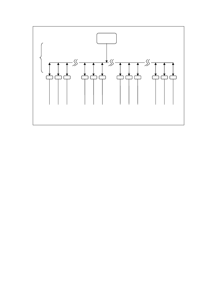
Figure 3 Flat KNX Topology
In really large projects, more than 225 KNX lines may be required (e.g. Heathrow Terminal
5). In this case it becomes necessary to divide the project into sub-projects and use different
IP multicast addresses for each. This allows the same physical address to be used more than
once as the transport telegrams are not routed between sub-projects.
1.2 Logical Project Structure
1.2.1 Group Addresses Limitations
It has been demonstrated above how a KNX project can be physically expanded to an almost
limitless size. However in reality it is the group address structure that comes under pressure
well before the physical address structure.
There can only be a maximum of 32 640 group addresses in one KNX project. When a
gateway to another protocol (e.g. DALI) is used, up to 250 group addresses can be used on a
single KNX device. In the worst possible case this would mean that a maximum of around
130 such devices can be used in a single project.
Currently ETS allows for either a two or three level structure. In the best case this can
accommodate 128 distinct categories (16 main groups x 8 middle groups). In large projects it
is particularly important to apply a rigid and logical structure to the group address allocations.
Whether you choose to allocate main and middle groups to function or location, it is apparent
that 128 categories do not go very far.
When the two factors above are combined, i.e. multiple gateways spread across a number of
locations, group addresses are easily exhausted. It is therefore necessary to adopt a different
strategy: re-use of group addresses.
1.2.2 Re-use of Group Addresses
Head End
PC
The use of IP over Ethernet results in area couplers becoming redundant.
1.1
1.2
1.3
1.15
2.1
2.2
2.15
3.1
3.2
15.13
15.14
15.15
…
…
…
IP
7
In the previous section a topology was demonstrated that utilised two modes of EIBNet/IP
communication (routing and tunnelling). The number of group addresses that are actually
required to be routed between KNX lines is typically fairly low. Examples include global
commands, time, date, etc.
It is therefore possible to designate one or two main groups that will be routed. The
remaining group addresses are then able to be replicated on each KNX line without any
concerns about conflicts.
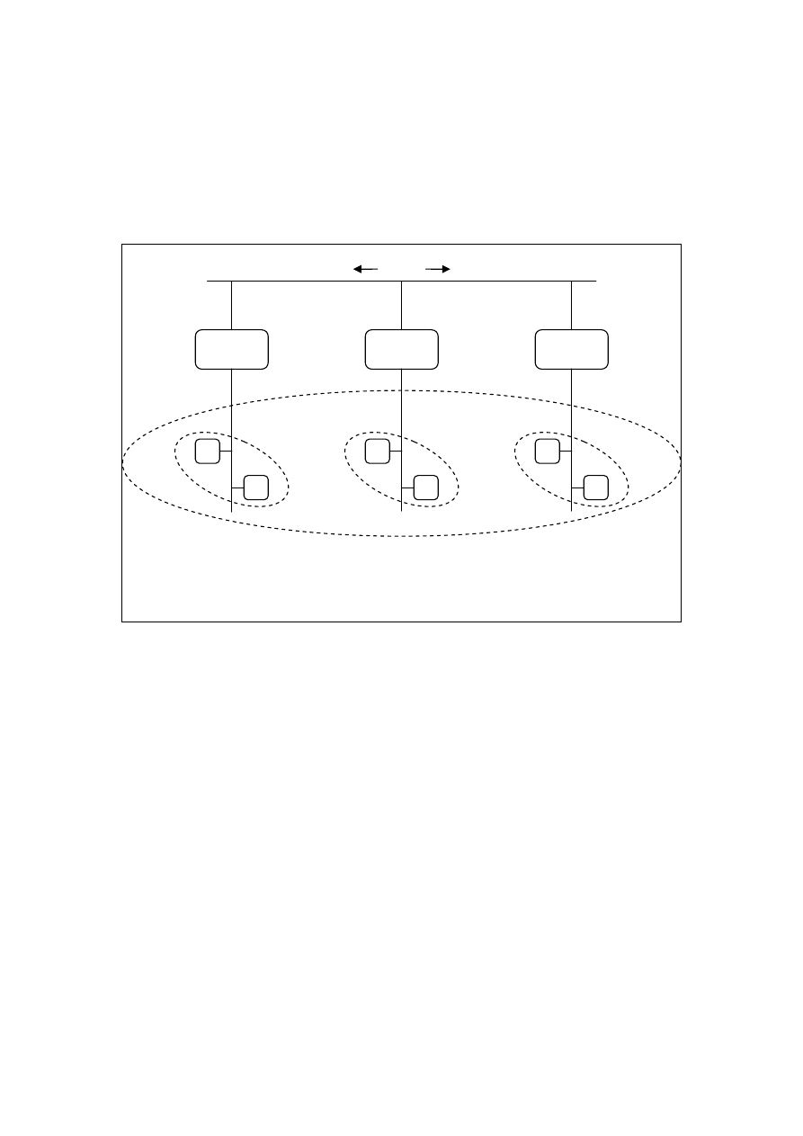
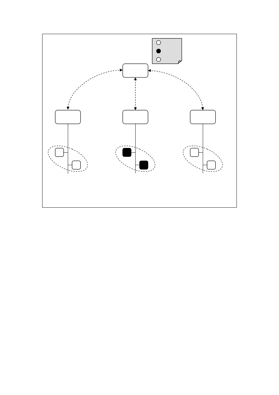
Figure 4 Group Address Re-use
Because each KNX/IP gateway is uniquely identified in the tunnelling or object server
connection, the head end PC is still able to distinguish between the same group address that
is repeated on each line.
KNX/IP
Gateway
KNX/IP
Gateway
KNX/IP
Gateway
Only one or two main groups are routed by the KNX/IP gateways – allowing global commands to be issued
across the project. Yet within each KNX line the non-routed group addresses can be re-used without conflicts.
7/1/1
7/1/1
0/1/1
7/1/1
0/*/*
8
Figure 5 Making Re-used Group Addresses Unique
1.2.3 Shortfall of Group Address Re-use
However it must be noted that the re-use of group addresses poses a number of problems.
Foremost is the fact that it is impossible to create a single ETS project where the same group
address is linked to multiple unrelated devices without causing complete confusion. It is
therefore necessary to split the ETS project into many individual projects, each with only one
KNX line. Yet this presents its own problems: there is no control over group addresses that
are to be routed and no safeguards against accidental duplication of physical addresses. This
issue is discussed further in Section 3.1.2 below.
KNX/IP
Gateway
KNX/IP
Gateway
KNX/IP
Gateway
Head End
PC
With a tunnelling or object server connection, each group address is prefixed by the KNX/IP gateway name
thereby making re-used group addresses appear unique to the head end.
A:7/1/1
B:7/1/1
C:0/1/1
A
B
C
A:7/1/1
B:7/1/1
C:7/1/1
9
2 KNX Product Advancement
2.1 Driving Factors for Large Projects
Large commercial customers who are investing significant sums of money in a control system
demand increased functionality from the system. At the same time a high level of reliability is
expected, which needs to be achieved by reducing the complexity of the system. This is
especially important when it comes to maintaining the system after handover. Unfortunately,
today’s economics dictate that the primary driving factor is reduced cost. At first it appears
that these factors contradict each other, especially given the relatively high cost per device of
KNX.
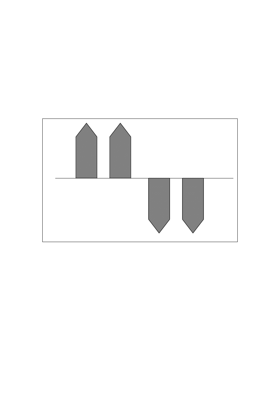
Figure 6 Driving Factors in System Design
Upon closer inspection though, these four factors can in fact be made to work together. If, in
a large system, the number of different devices is reduced to a bare minimum, then the
volumes per device are increased, reducing cost by creating an economy of scale. As there
are only a limited number of devices that need to work together, overall complexity is
decreased while at the same time reliability is increased, as the system now relies on fewer
elements for correct operation.
Heathrow Terminal 5, for example, consists of 300 lines with more than 7 000 devices – yet
only 5 different device types are used, including the KNX power supply unit.
However, in order to meet the control requirements, it becomes necessary to increase the
functionality per device. To achieve this, ATL have had to work in close partnership with KNX
manufacturers and have jointly developed a number of advanced KNX devices.
F
u
n
c
ti
o
n
a
li
ty
R
e
li
a
b
il
it
y
C
o
m
p
le
x
it
y
C
o
s
t

10
2.2 Special KNX-DALI gateway enhancements.
Within a single device, the Siemens GE141 KNX-DALI gateway, the following additional
features have been implemented:
•
Ability to control and monitor DALI luminaires in groups and individually.
The Siemens gateway allows normal lighting to be controlled and monitored as part
of a group. Yet the monitoring of emergency luminaires is done individually because
errors need to be identified and corrected as soon as possible.
•
Dynamic management of failure information.
On a large project there could be over 50 000 luminaires. For each luminaire the
lamp and ECG status can be reported. This can easily translate into one alarm every
2-3 hours. If alarms are raised this frequently the operator becomes swamped and
the information becomes worthless.
Since it is not always necessary to react to the first failure in a large area, the
Siemens gateway reports the failures in any group as a relative value, i.e. the
number of failures vs. the number of luminaires. Once the number of failures has
exceeded a predetermined level (e.g. 15%) then maintenance can commence.
The gateway dynamically updates luminaire information so that as new luminaires
are added the failure information will reflect the new total quantity of luminaires. This
means that the head end does not need to be modified every time a new luminaire is
added.
•
Local circuit failure monitoring.
When the mains supply to a local circuit is lost, the default DALI behaviour results in
all emergency luminaires controlled by the local gateway reverting to a default level
(usually 100%). At the same time the gateway is able to sense this power failure and
relay the message to neighbouring gateways over the KNX bus. The neighbouring
gateways then also ensure that their luminaires revert to the emergency level. For
the duration of the failure, and until all supplies are healthy, any switch and dim
commands are ignored.
•
Central Battery Emergency Testing
Statutory regulations require that the central battery system be tested regularly. In
order to achieve this the gateway can be put into an emergency mode via a KNX
command without the need to switch off supply circuits. While in this mode all
emergency lighting is set to the emergency level, and all switch and dim commands
are ignored. This ensures that the central battery experiences a full load for the
duration of the test.
•
Self Contained Emergency Testing
Some manufacturers have introduced intelligent inverters that are able to
communicate over DALI. The Siemens gateway has implemented the additional DALI
commands that the emergency testing protocol requires.
The gateway is able to configure the inverter to perform weekly, monthly and annual
self tests. All test results and failures are relayed over the KNX bus, including useful
information such as battery level, inverter status, etc.

11
2.3 Special KNX - IP Gateway Enhancements.
A single unit from IPAS, the MCG-R, has all of the following features:
•
EIBNet/IP Routing
The IPAS gateway is able to route certain group addresses between KNX lines over a
specified multicast address.
•
EIBNet/IP Object Server Connection
The gateway can accept object server connections from, e.g. the Head End. This
allows for the control and visualisation of all group addresses that exist on the KNX
line without the group addresses being routed.
•
EIBNet/IP Tunnelling
The IPAS gateway allows for tunnelling in addition to the object server connection.
This allows for ETS to connect to the KNX line at the same time as the Head End PC.
This means that maintenance can be performed on the KNX line from ETS without
disrupting the flow of information between the head end and the bus.
•
Scene Controller
The gateway has an advanced scene controlling element that can control up to 80
group addresses over 200 scene elements. In addition a time factor can be
introduced to any scene, allowing the implementation of staircase timers, etc.
Furthermore, it is possible that any scene can be cancelled by another trigger event.
•
IP based Scheduler
The IPAS gateway has a scheduler that is able to operate on up to 80 group
addresses. In large systems it is important that the end user is able to modify the
schedules without having to involve a specialist KNX contractor.
The gateway is able to accept and update new schedules over its IP connection. This
makes it possible for the head end to modify the schedule, but at the same time the
system is robust in that each KNX line does not rely on any other KNX line, the head
end or the IT network for the successful day to day scheduling of events.

12
3 Commissioning and Maintenance
When implementing very large KNX projects, there are a number of limitations introduced by
the traditional ETS-based methods of commissioning and maintenance. These limitations are
due to two primary factors:
•
ETS does not explicitly support multiple users working concurrently on a single project
database
•
The skill levels required for the use of ETS means that maintenance operations are more
complex and expensive
3.1 Multiple Users Working Concurrently
3.1.1 Subdivision of Large Projects
When implementing a large KNX project the device count is too high for a single engineer to
be responsible for the configuration of every device. In order to allow a team of engineers to
work concurrently, ATL have devised a method whereby a large project is broken up into a
number of smaller sub-projects, each of which is connected to its own KNX - IP gateway and
is contained within a separate ETS database. This makes it possible for each database to be
worked on individually both for configuration and commissioning. However, adopting this
strategy means that ETS is no longer to able to automatically create filter tables for the
KNX - IP gateways and cannot prevent the same group addresses or physical addresses being
re-used across multiple projects. While re-using group addresses and physical addresses is
not a typical ETS approach, it is not impossible to do so and as explained in Section 1.2.2, it
becomes essential in order to accommodate the high number of group addresses required for
larger projects. The proviso is that the use of group addresses and physical addresses across
multiple projects has to be very tightly controlled
.
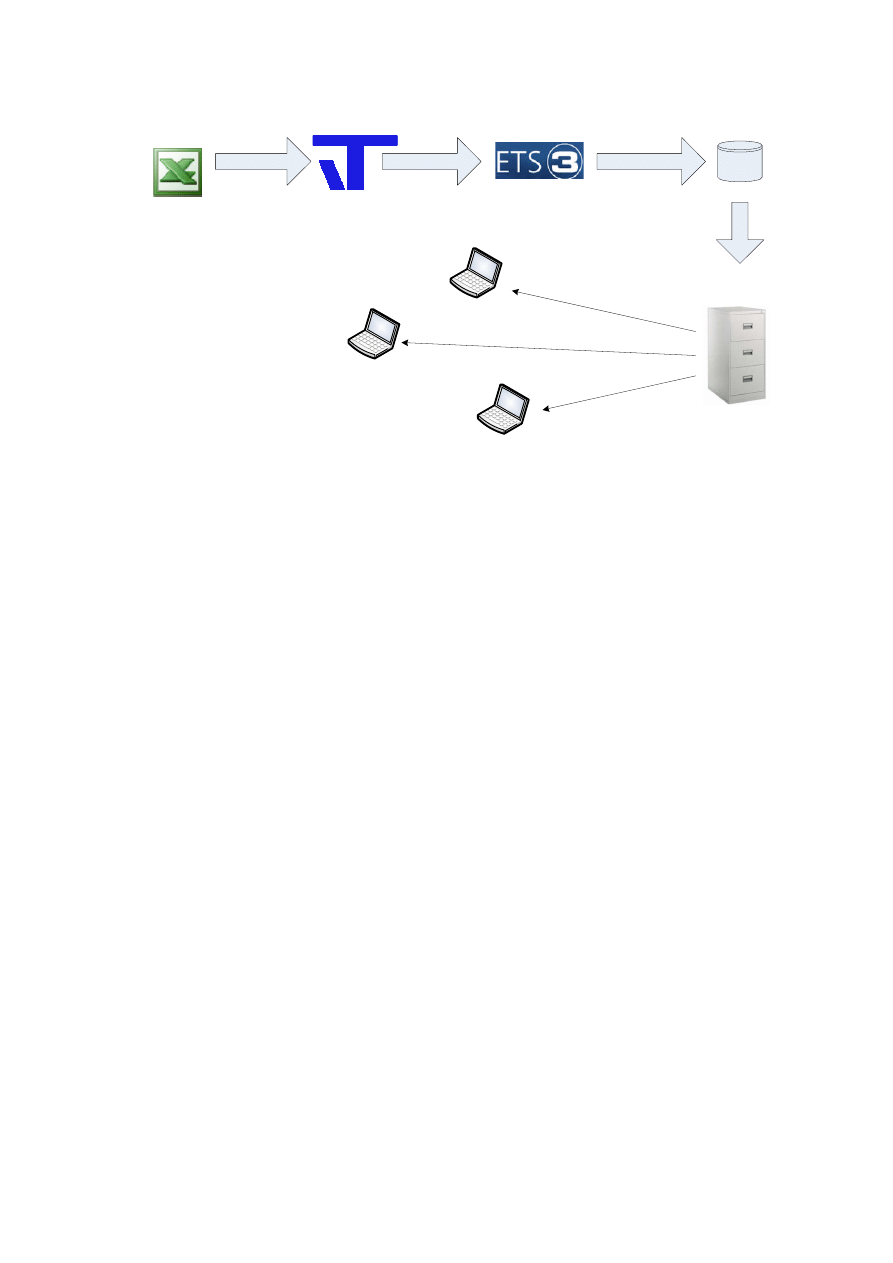
3.1.2 Maintaining Control with a “Master” Spreadsheet
The overall control and integration of all the separate ETS databases is achieved through
extensive use of Microsoft Excel and the IT Tools macros. Using these tools allows the
generation of fully functional ETS databases without users having to manually assign physical
addresses, edit device parameters or assign group addresses. As shown in Figure 7 below,
the ATL workflow uses a system whereby a “master” Excel spreadsheet is used to control
which group/physical addresses are re-used across ETS databases and also ensures that filter
tables within KNX - IP gateways are setup to allow communication between sub-projects
where necessary.
13
Export CSV files
Import CSV files
Excel Master
Spreadsheet
IT Tools Macros
Create ETS database
DB File
Version Control
Repository
S
to
re
d
Commissioning
Engineer
Commissioning
Engineer
Commissioning
Engineer
Figure 7 ETS Database Generation via Microsoft Excel and IT Tools Macros
This method also ensures that devices and group addresses are named and assigned
consistently and that a single set of parameters can be globally applied to all devices
within the greater project, as opposed to relying on the personal preferences and
practices of individual engineers. Finally, because all sub-projects are coordinated by a
single master spreadsheet, it is possible to run automated post-configuration checks that
can identify any conflicting configuration data, physical addresses and group addresses.
3.2 High Skill Levels Required For Commissioning and Maintenance
For most standard KNX installations, relatively little change or maintenance is required
after the project has been handed over and the client is generally prepared to retain a
KNX integrator on a service contract basis. With larger installations, though, the client
often requires constant modifications to suit changing site conditions (e.g. changing
floorplans, new tenants etc.). In addition, the sheer number of devices dictates that
hardware failure will be a significant factor and will require a substantial number of hours
to replace faulty parts. In these cases the client commonly wishes to avoid the high
callout fee of skilled contractors and prefers to use its own dedicated on-site maintenance
teams. Unfortunately, modifying and replacing KNX devices requires ETS skills beyond
those possessed by typical maintenance teams. The client is thus left with having to
choose between purchasing costly licenses for ETS software and training maintenance
technicians to use it, or paying the relatively high rates demanded by skilled KNX
contractors. Neither option is ideal and can count heavily against the choice of KNX to
start with.
It must be said that with a system as powerful as KNX it is inevitable that some level of
skill is necessary for its setup and maintenance. ATL have therefore concentrated on
reducing the required skill levels for some of the more common tasks, leaving
complicated operations to skilled KNX engineers. In particular, an ETS-independent
system for commissioning and maintaining DALI fittings attached to a KNX – DALI
gateway has been developed to allow reduced commissioning costs and greatly improved
ease of maintenance.

14
3.2.1 DALI Commissioning and Maintenance
Over the past few years, DALI has experienced an unprecedented growth. A larger
variety of DALI products is now available and prices are dropping continuously. When
used in conjunction with KNX via a KNX – DALI gateway, the flexibility and functionality
offered by DALI is exceptional. However, the uptake of DALI is still being hampered by
customers’ perception that it is difficult to commission and maintain. While it is beyond
the scope of this document to describe the DALI commissioning process in detail, it is
briefly explained as follows:
1. The KNX – DALI gateway is configured to control a given number of DALI fittings
which may be grouped in various ways (e.g. 10 fittings in a reception hall may all
be part of a single group that is turned on and off via a particular group
address).
2. Once connected to the DALI bus, the KNX – DALI bus automatically discovers all
DALI devices that are connected to it. In a perfect scenario the number of
detected DALI devices will exactly match the number of DALI fittings for which
the gateway has been configured.
3. Each DALI device within the system is flashed at random.
4. While the DALI device is flashing, the engineer must link it to the corresponding
fitting (e.g. a flashing lamp over a reception desk will be linked to the fitting that
is labeled as such).
While this may seem relatively simple, one must consider that almost all construction
sites are not built exactly according to plan. Thus a KNX – DALI gateway may be
configured to control a certain number of DALI devices that are shown in the plans, while
the actual number of devices that are installed on site may differ. This requires further
skill on the part of the commissioning engineer to be able to reconfigure the KNX – DALI
gateway on an ad hoc basis. With this in mind, ATL set out to develop a tool that would
simplify the DALI commissioning process to the extent that it could be performed by a
commissioning engineer with minimal training.
15
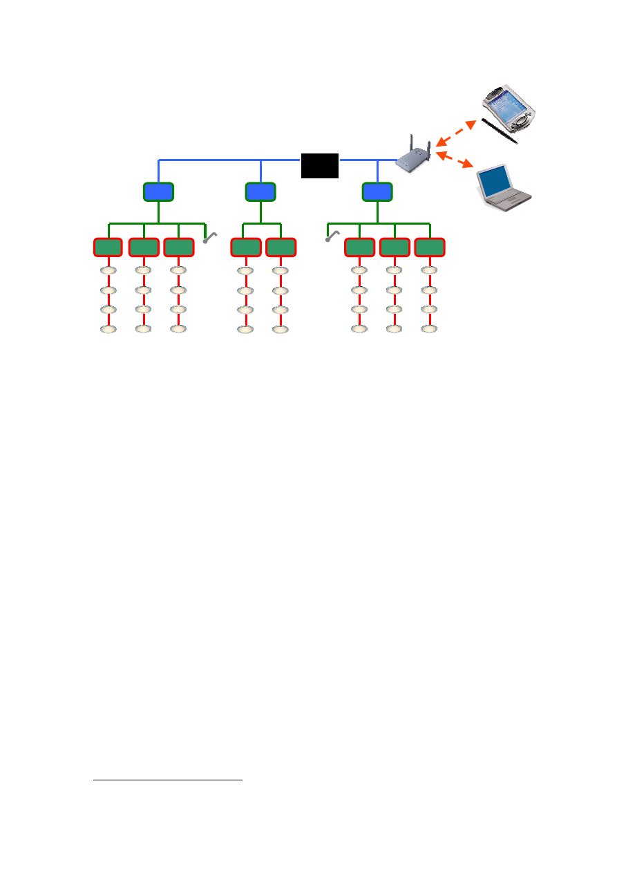
Figure 8 DALI Commissioning Tool
Figure 8 above shows the basic outline of the DALI commissioning and maintenance tool
developed by ATL. As shown in the diagram, user interaction takes place via a handheld
PDA which interacts wirelessly with a web server running on an embedded platform. The
embedded platform is connected via a suitable bus coupler to the KNX bus. Information
input by the users on the PDA is processed on the embedded platform which then
generates the necessary KNX communications. The current generation of embedded
platforms are running Linux and using open source software developed by the University
of Vienna to achieve this.
Through careful design in close consultation with commissioning engineers, ATL have
created an intuitive user interface that allows rapid commissioning and also guides
engineers through re-configuring the KNX – DALI gateway on site when necessary.
Whereas previously the replacement of faulty DALI devices required skilled technicians,
this same tool can now be used by relatively low skilled maintenance teams.
3.3 Proactive Maintenance
As described in Section 1.1.3, the IP-based backbone is used to feedback a large volume of
data to a head end PC. This data includes device failure information which is processed by
custom software modules residing on the head end PC. This allows detailed maintenance
schedules to be implemented wherein certain devices are only replaced when a threshold
number of faulty devices have been detected, while other safety critical devices are replaced
immediately1. Furthermore, the custom software modules are able to compute the run hours
of individual lamps to facilitate an optimal replacement strategy. On large sites where
permits and special equipment (scaffolding, cherry pickers etc.) may be required for
maintaining certain areas, planning of this nature ensures minimal disruption and greatly
reduces costs.
1
This is described in greater detail in Section 2.2
KNX-DALI
Gateway
KNX-DALI
Gateway
KNX-DALI
Gateway
KNX-DALI
Gateway
KNX-DALI
Gateway
KNX-DALI
Gateway
KNX-DALI
Gateway
KNX-DALI
Gateway
IP-KNX
Gateway
IP-KNX
Gateway
IP-KNX
Gateway
KNX
DALI
IP
Embedded
Platform
16
4 Suggested ETS Improvements
While much of the ATL design, configuration and commissioning process is now relatively
independent of ETS, the ETS package itself is still central to any KNX project. Recent
versions of ETS have all offered substantial improvements over their predecessors, but there
are a few areas in which a small amount of development would result in significant benefits
to KNX integrators.
4.1 Concurrent Access through XML Data Export/Import
Because KNX is an open standard, any KNX project should be configurable and maintainable
by any KNX qualified operator. This makes it essential to ensure that all projects are fully
compatible with ETS (i.e. there should be no custom installations that cannot later be
modified through ETS). However, as KNX projects become increasingly larger it is apparent
that there needs to be a way in which a single ETS database can be accessed concurrently by
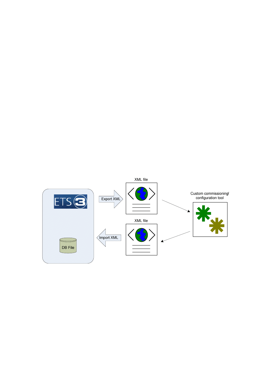
multiple users. This is already implemented to a certain extent with the Siemens KNX – DALI
gateway which can export relevant configuration data in an XML file with a well documented
format. This XML file is then used by a third party tool for configuration or maintenance and
updated configuration data is then written back to the XML file. The modified XML file can
then be re-imported to ETS, fulfilling the vital requirement that the whole project is still
completely accessible to ETS. This is shown diagrammatically in Figure 9 below.
Figure 9 Export and Import of Data from ETS
The application of this export/import method to every KNX device within an ETS project
would dramatically increase the potential of the KNX system as a whole.
4.2 Version Control
When controlling large sites (and especially commercial sites with high public profile), even
the smallest changes can have far reaching consequences. As such it is imperative to retain
a comprehensive record of all changes and have the capability to revert to a previous
configuration in the event that an engineer makes changes that have unforeseen

17
consequences. Moreover, version control is indispensable in ensuring that only the most up
to date version of an ETS database is used for configuration and maintenance (this is an
especially salient point when multiple engineers are working on the same project).
As shown in Figure 7, ATL have implemented a stand alone version control system to store
ETS database files. However, ETS currently has very limited support for version control.
Critically, it alters the structure of a database file simply by opening it (i.e. even if no changes
whatsoever are made to the project). Thus for a given database file, it appears that
modifications have been made every time that the file is opened by ETS. Changing this
behaviour of ETS would massively improve its compatibility with version control systems.
4.3 Access Control
There are cases when the client is willing to train maintenance teams in the basic use of ETS.
While this allows greater flexibility for the client, it introduces the possibility that
misunderstood changes can be made due to the limited KNX experience of maintenance
teams. It also creates difficulties in maintaining a single up to date ETS database as the
client’s ETS database will no longer be identical to the database retained by the integrator.
This could be remedied by a two level access control system allowing restricted access to the
maintenance teams. In this restricted mode, users would be able to address and download
to replacement KNX devices being installed in the place of failed parts. However, they would
be prevented from making any changes to the configuration of the project itself. The client
would thus be self sufficient in terms of replacing broken parts, but would not be able to
corrupt the integrity of the KNX installation. The KNX integrator could also be assured that
their ETS database contains a complete record of all configuration data.
Wyszukiwarka
Podobne podstrony:
15 ATL 2006 Up scaling KNX for large projects
LBC3090 31 15 03 2006 PA PL F
Party Games for Large Groups of Teenagers
LBC3011 x1 15 03 2006 PA PL F
LBC1259 00 15 03 2006 PA PL F
LBC340x 15 15 03 2006 PA PL F
LBC1256 00 15 03 2006 PA PL F
LA1 UW24 x 15 03 2006 PA PL F
LBC2900 xx 15 03 2006 PA PL F
LBB1949 00 15 03 2006 PA PL F
LBC1227 01 15 03 2006 PA PL F
LBC3087 41 15 03 2006 PA PL F
LBB1990 00 15 03 2006 PA PL F
MW1 RX Fx 15 05 2006 DS PA PL F
LBC3950 01 15 03 2006 PA PL F
LBC3951 11 15 03 2006 PA PL F
LB1 UW12 x 15 03 2006 PA PL F
test 15.02.2006 (kilka pyt), FARMAKOLOGIA TEST 15
15 07 2006 wersja A
więcej podobnych podstron