
2205-6508
34 pages
M05/4/PHYSI/HP2/ENG/TZ1/XX+
Thursday 19 May 2005 (afternoon)
PHYSICS
HIGHER LEVEL
PAPER 2
IB DIPLOMA PROGRAMME
PROGRAMME DU DIPLÔME DU BI
PROGRAMA DEL DIPLOMA DEL BI
INSTRUCTIONS TO CANDIDATES
•
Write your session number in the boxes above.
•
Do not open this examination paper until instructed to do so.
•
Section A: answer all of Section A in the spaces provided.
•
Section B: answer two questions from Section B in the spaces provided.
•
At the end of the examination, indicate the numbers of the questions answered in the candidate box
on your cover sheet.
2 hours 15 minutes
Candidate session number
0
0
22056508
0133
2205-6508
– 2 –
M05/4/PHYSI/HP2/ENG/TZ1/XX+
SECTION A
Answer all the questions in the spaces provided.
A1. Data analysis question
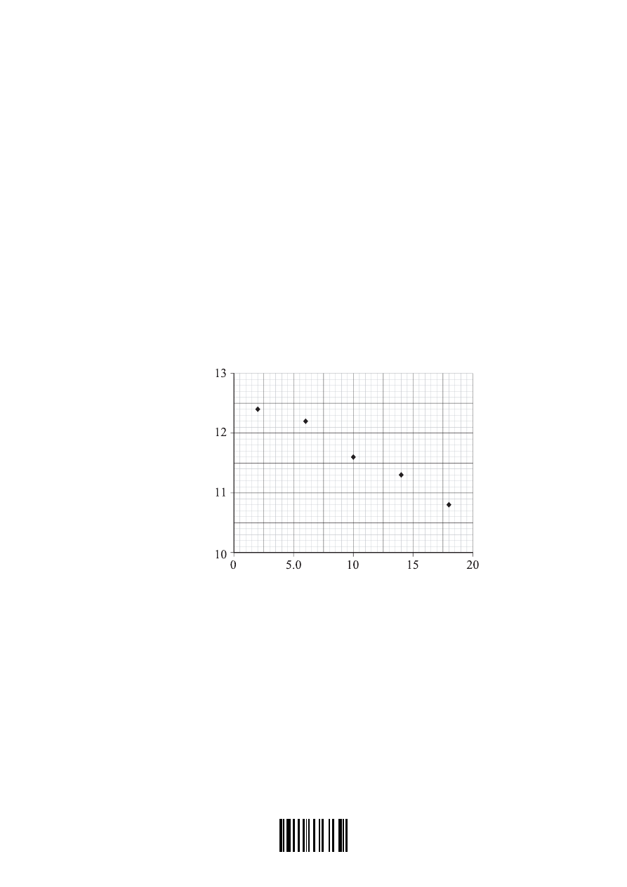
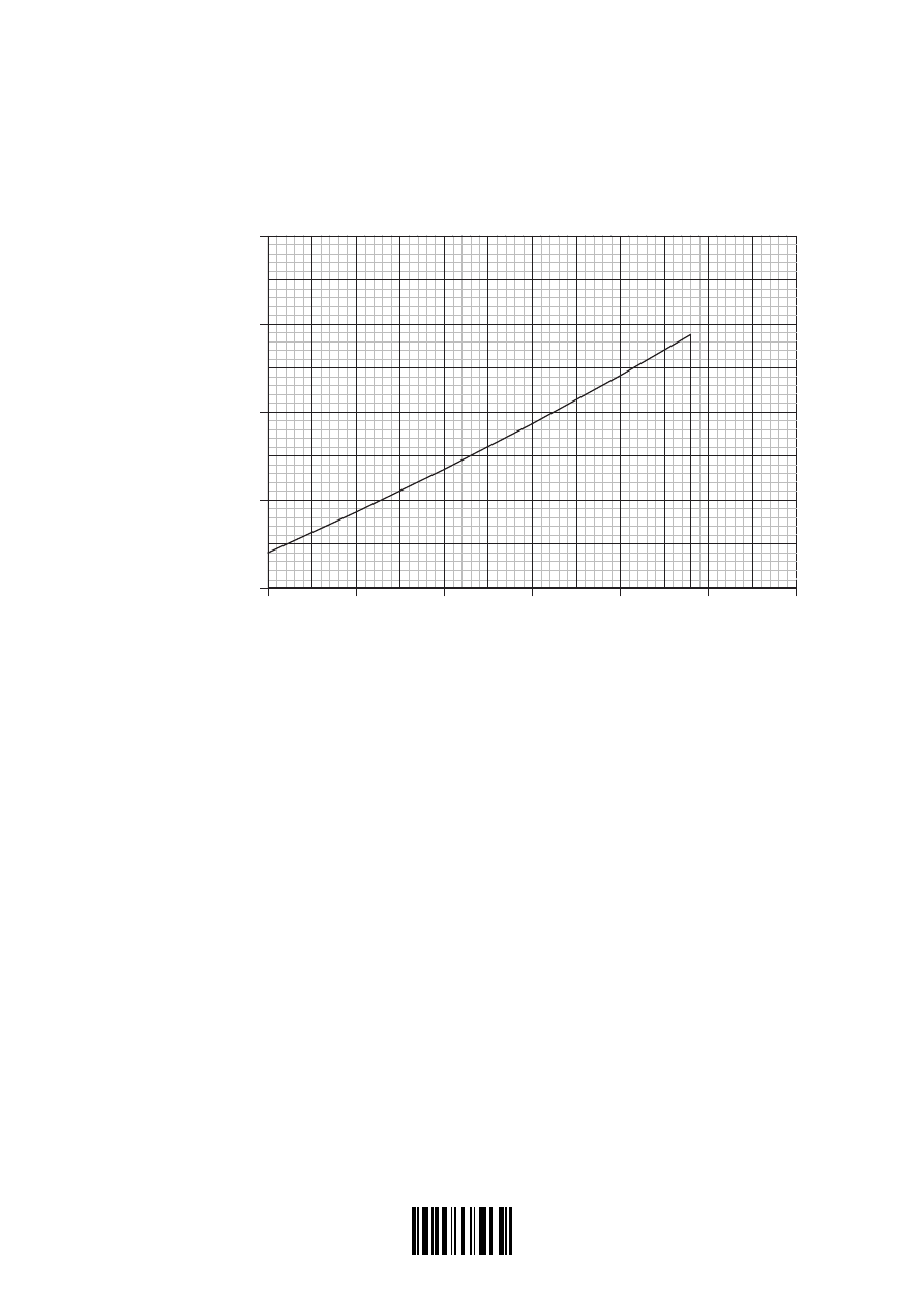
At high pressures, a real gas does not behave as an ideal gas. For a certain range of pressures,
it is suggested that the relation between the pressure P and volume V of one mole of the gas at
constant temperature is given by the equation
PV A BP
= +
where A and B are constants.
In an experiment to measure the deviation of nitrogen gas from ideal gas behaviour, 1 mole
of nitrogen gas was compressed at a constant temperature of 150 K. The volume V of the gas
was measured for different values of the pressure P. A graph of the product PV of pressure
and volume was plotted against the pressure P and is shown below. (Error bars showing the
uncertainties in measurements are not shown).
PV /
PV /×10
2
N m
P /
P /×10
6
Pa
(a) Draw a line of best fit for the data points.
[1]
(This question continues on the following page)
0233

2205-6508
– 3 –
Turn over
M05/4/PHYSI/HP2/ENG/TZ1/XX+
(Question A1 continued)
(b) Use the graph to determine the values of the constants A and B in the equation
PV A BP
= +
.
[5]
Constant A
. . . . . . . . . . . . . . . . . . . . . . . . . . . . . . . . . . . . . . . . . . . . . . . . . . . . . . . . . . . . . . . . .
. . . . . . . . . . . . . . . . . . . . . . . . . . . . . . . . . . . . . . . . . . . . . . . . . . . . . . . . . . . . . . . . .
. . . . . . . . . . . . . . . . . . . . . . . . . . . . . . . . . . . . . . . . . . . . . . . . . . . . . . . . . . . . . . . . .
Constant B . . . . . . . . . . . . . . . . . . . . . . . . . . . . . . . . . . . . . . . . . . . . . . . . . . . . . . . . . . . .
. . . . . . . . . . . . . . . . . . . . . . . . . . . . . . . . . . . . . . . . . . . . . . . . . . . . . . . . . . . .
. . . . . . . . . . . . . . . . . . . . . . . . . . . . . . . . . . . . . . . . . . . . . . . . . . . . . . . . . . . .
. . . . . . . . . . . . . . . . . . . . . . . . . . . . . . . . . . . . . . . . . . . . . . . . . . . . . . . . . . . .
. . . . . . . . . . . . . . . . . . . . . . . . . . . . . . . . . . . . . . . . . . . . . . . . . . . . . . . . . . . .
(c) State the value of the constant B for an ideal gas.
. . . . . . . . . . . . . . . . . . . . . . . . . . . . . . . . . . . . . . . . . . . . . . . . . . . . . . . . . . . . . . . . . . . . . .
[1]
(d) The equation
PV A BP
= +
is valid for pressures up to
6 0 10
7
. ×
Pa
.
(i) Determine the value of PV for nitrogen gas at a pressure of
6 0 10
7
. ×
Pa
.
. . . . . . . . . . . . . . . . . . . . . . . . . . . . . . . . . . . . . . . . . . . . . . . . . . . . . . . . . . . . . . . . .
. . . . . . . . . . . . . . . . . . . . . . . . . . . . . . . . . . . . . . . . . . . . . . . . . . . . . . . . . . . . . . . . .
. . . . . . . . . . . . . . . . . . . . . . . . . . . . . . . . . . . . . . . . . . . . . . . . . . . . . . . . . . . . . . . . .
[2]
(ii) Calculate the difference between the value of PV for an ideal gas and nitrogen gas
when both are at a pressure of
6 0 10
7
. ×
Pa
.
. . . . . . . . . . . . . . . . . . . . . . . . . . . . . . . . . . . . . . . . . . . . . . . . . . . . . . . . . . . . . . . . .
. . . . . . . . . . . . . . . . . . . . . . . . . . . . . . . . . . . . . . . . . . . . . . . . . . . . . . . . . . . . . . . . .
. . . . . . . . . . . . . . . . . . . . . . . . . . . . . . . . . . . . . . . . . . . . . . . . . . . . . . . . . . . . . . . . .
[2]
(e) In the original experiment, the pressure P was measured to an accuracy of 5 % and the
volume V was measured to an accuracy of 2 %. Determine the absolute error in the value
of the constant A.
. . . . . . . . . . . . . . . . . . . . . . . . . . . . . . . . . . . . . . . . . . . . . . . . . . . . . . . . . . . . . . . . . . . . . .
. . . . . . . . . . . . . . . . . . . . . . . . . . . . . . . . . . . . . . . . . . . . . . . . . . . . . . . . . . . . . . . . . . . . . .
. . . . . . . . . . . . . . . . . . . . . . . . . . . . . . . . . . . . . . . . . . . . . . . . . . . . . . . . . . . . . . . . . . . . . .
[3]
0333
2205-6508
– 4 –
M05/4/PHYSI/HP2/ENG/TZ1/XX+
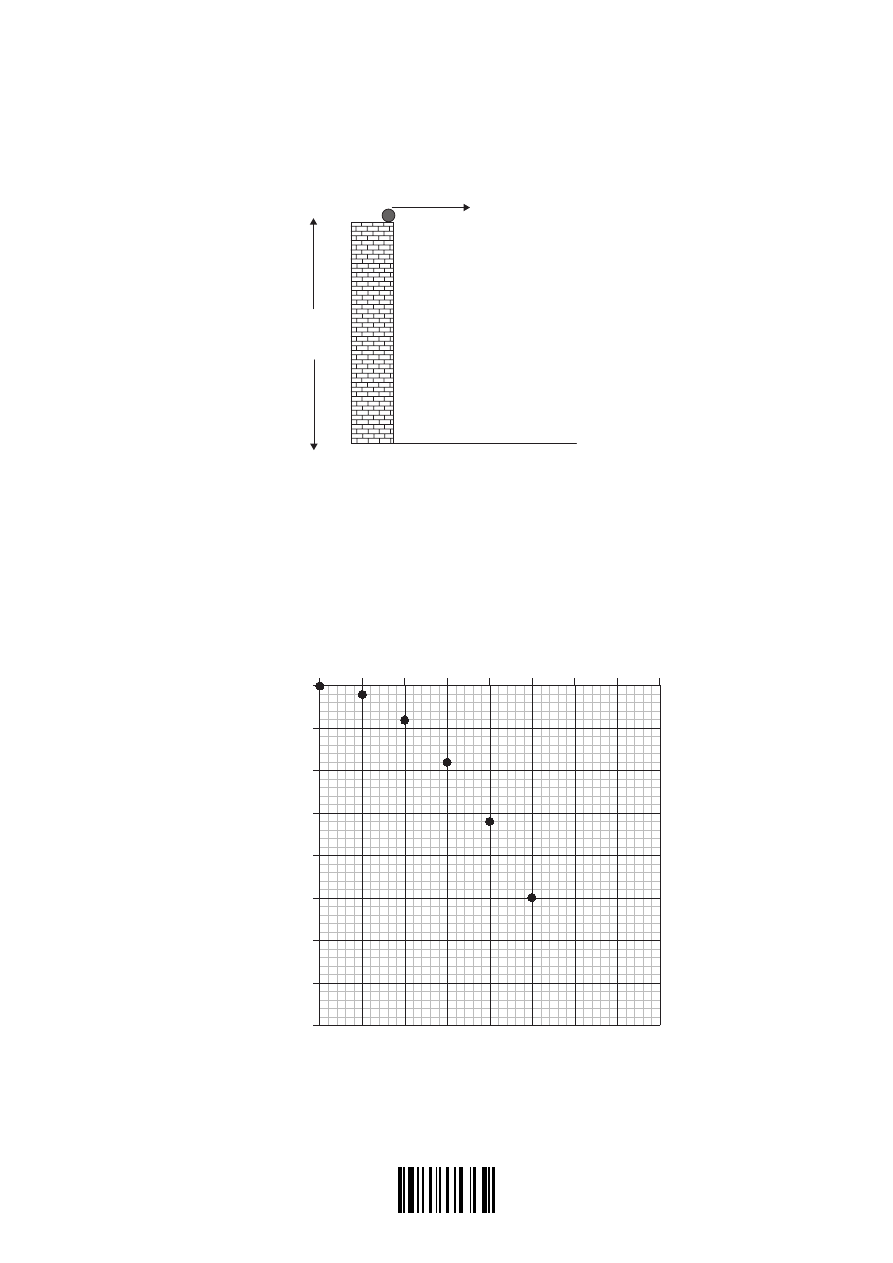
A2. This question is about projectile motion.
A marble is projected horizontally from the edge of a wall 1.8 m high with an initial speed V.
V
1.8 m
ground
A series of flash photographs are taken of the marble. The photographs are combined into a
single photograph as shown below. The images of the marble are superimposed on a grid that
shows the horizontal distance x and vertical distance y travelled by the marble.
The time interval between each image of the marble is 0.10 s.
x / m
0
0.50
1.0
1.5
2.0
y / m
0
– 0.50
– 1.0
– 1.5
– 2.0
(a) On the images of the marble at x
x = 0.5 m
0.5 m and x
x = 0.5 m
1.0 m, draw arrows to represent the
horizontal velocity
V
H
and vertical velocity
V
V
.
[2]
(This question continues on the following page)
0433

2205-6508
– 5 –
Turn over
M05/4/PHYSI/HP2/ENG/TZ1/XX+
(Question A2 continued)
(b) On the photograph, draw a suitable line to determine the horizontal distance d from the
base of the wall to the point where the marble hits the ground. Explain your reasoning.
. . . . . . . . . . . . . . . . . . . . . . . . . . . . . . . . . . . . . . . . . . . . . . . . . . . . . . . . . . . . . . . . . . . . . .
. . . . . . . . . . . . . . . . . . . . . . . . . . . . . . . . . . . . . . . . . . . . . . . . . . . . . . . . . . . . . . . . . . . . . .
. . . . . . . . . . . . . . . . . . . . . . . . . . . . . . . . . . . . . . . . . . . . . . . . . . . . . . . . . . . . . . . . . . . . . .
[3]
(c) Use data from the photograph to calculate a value of the acceleration of free fall.
. . . . . . . . . . . . . . . . . . . . . . . . . . . . . . . . . . . . . . . . . . . . . . . . . . . . . . . . . . . . . . . . . . . . . .
. . . . . . . . . . . . . . . . . . . . . . . . . . . . . . . . . . . . . . . . . . . . . . . . . . . . . . . . . . . . . . . . . . . . . .
. . . . . . . . . . . . . . . . . . . . . . . . . . . . . . . . . . . . . . . . . . . . . . . . . . . . . . . . . . . . . . . . . . . . . .
[3]
0533
2205-6508
– 6 –
M05/4/PHYSI/HP2/ENG/TZ1/XX+
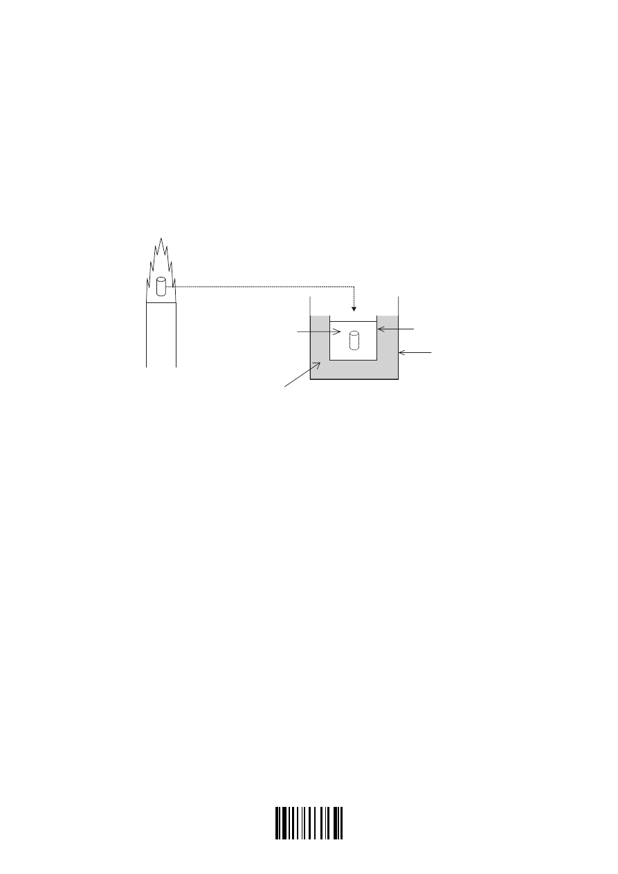
A3. This question is about an experiment to measure the temperature of a flame.
(a) Define heat (thermal) capacity
. . . . . . . . . . . . . . . . . . . . . . . . . . . . . . . . . . . . . . . . . . . . . . . . . . . . . . . . . . . . . . . . . . . . . .
. . . . . . . . . . . . . . . . . . . . . . . . . . . . . . . . . . . . . . . . . . . . . . . . . . . . . . . . . . . . . . . . . . . . . .
[1]
A piece of metal is held in the flame of a Bunsen burner for several minutes. The metal is then
quickly transferred to a known mass of water contained in a calorimeter.
flame
water
calorimeter
container
Bunsen burner
lagging (insulation)
The water into which the metal has been placed is stirred until it reaches a steady temperature.
(b) Explain why
(i) the metal is transferred as quickly as possible from the flame to the water.
. . . . . . . . . . . . . . . . . . . . . . . . . . . . . . . . . . . . . . . . . . . . . . . . . . . . . . . . . . . . . . . . .
. . . . . . . . . . . . . . . . . . . . . . . . . . . . . . . . . . . . . . . . . . . . . . . . . . . . . . . . . . . . . . . . .
[1]
(ii) the water is stirred.
. . . . . . . . . . . . . . . . . . . . . . . . . . . . . . . . . . . . . . . . . . . . . . . . . . . . . . . . . . . . . . . . .
. . . . . . . . . . . . . . . . . . . . . . . . . . . . . . . . . . . . . . . . . . . . . . . . . . . . . . . . . . . . . . . . .
[1]
(This question continues on the following page)
0633

2205-6508
– 7 –
Turn over
M05/4/PHYSI/HP2/ENG/TZ1/XX+
(Question A3 continued)
The following data are available:
heat capacity of metal
= 82 7
. J K
-1
J K
–1
heat capacity of the water in the calorimeter
=
×
5 46 10
2
.
J K
-1
J K
–1
heat capacity of the calorimeter
= 54 6
. J K
-1
J K
–1
initial temperature of the water
= 288 K
K
final temperature of the water
= 353 K
K
(c) Assuming negligible energy losses in the processes involved, use the data to calculate the
temperature T of the Bunsen flame.
. . . . . . . . . . . . . . . . . . . . . . . . . . . . . . . . . . . . . . . . . . . . . . . . . . . . . . . . . . . . . . . . . . . . . .
. . . . . . . . . . . . . . . . . . . . . . . . . . . . . . . . . . . . . . . . . . . . . . . . . . . . . . . . . . . . . . . . . . . . . .
. . . . . . . . . . . . . . . . . . . . . . . . . . . . . . . . . . . . . . . . . . . . . . . . . . . . . . . . . . . . . . . . . . . . . .
. . . . . . . . . . . . . . . . . . . . . . . . . . . . . . . . . . . . . . . . . . . . . . . . . . . . . . . . . . . . . . . . . . . . . .
. . . . . . . . . . . . . . . . . . . . . . . . . . . . . . . . . . . . . . . . . . . . . . . . . . . . . . . . . . . . . . . . . . . . . .
. . . . . . . . . . . . . . . . . . . . . . . . . . . . . . . . . . . . . . . . . . . . . . . . . . . . . . . . . . . . . . . . . . . . . .
[4]
0733

2205-6508
– 8 –
M05/4/PHYSI/HP2/ENG/TZ1/XX+
A4. This question is about the photoelectric effect.
The following are two observations relating to the emission of electrons from a metal surface
when light of different frequencies and different intensities is incident on the surface.
I.
There exists a frequency of light (the threshold frequency) below which no electrons are
emitted whatever the intensity of the light.
II. For light above the threshold frequency, the emission of the electrons is instantaneous
whatever the intensity of the light.
Explain why the wave model of light is unable to account for these observations.
[6]
Observation I . . . . . . . . . . . . . . . . . . . . . . . . . . . . . . . . . . . . . . . . . . . . . . . . . . . . . . . . . . . . . .
. . . . . . . . . . . . . . . . . . . . . . . . . . . . . . . . . . . . . . . . . . . . . . . . . . . . . . . . . . . . . .
. . . . . . . . . . . . . . . . . . . . . . . . . . . . . . . . . . . . . . . . . . . . . . . . . . . . . . . . . . . . . .
. . . . . . . . . . . . . . . . . . . . . . . . . . . . . . . . . . . . . . . . . . . . . . . . . . . . . . . . . . . . . .
. . . . . . . . . . . . . . . . . . . . . . . . . . . . . . . . . . . . . . . . . . . . . . . . . . . . . . . . . . . . . .
. . . . . . . . . . . . . . . . . . . . . . . . . . . . . . . . . . . . . . . . . . . . . . . . . . . . . . . . . . . . . .
. . . . . . . . . . . . . . . . . . . . . . . . . . . . . . . . . . . . . . . . . . . . . . . . . . . . . . . . . . . . . .
Observation II . . . . . . . . . . . . . . . . . . . . . . . . . . . . . . . . . . . . . . . . . . . . . . . . . . . . . . . . . . . . . .
. . . . . . . . . . . . . . . . . . . . . . . . . . . . . . . . . . . . . . . . . . . . . . . . . . . . . . . . . . . . . .
. . . . . . . . . . . . . . . . . . . . . . . . . . . . . . . . . . . . . . . . . . . . . . . . . . . . . . . . . . . . . .
. . . . . . . . . . . . . . . . . . . . . . . . . . . . . . . . . . . . . . . . . . . . . . . . . . . . . . . . . . . . . .
. . . . . . . . . . . . . . . . . . . . . . . . . . . . . . . . . . . . . . . . . . . . . . . . . . . . . . . . . . . . . .
. . . . . . . . . . . . . . . . . . . . . . . . . . . . . . . . . . . . . . . . . . . . . . . . . . . . . . . . . . . . . .
. . . . . . . . . . . . . . . . . . . . . . . . . . . . . . . . . . . . . . . . . . . . . . . . . . . . . . . . . . . . . .
0833

2205-6508
– 9 –
Turn over
M05/4/PHYSI/HP2/ENG/TZ1/XX+
Blank page
0933
2205-6508
– 10 –
M05/4/PHYSI/HP2/ENG/TZ1/XX+
SECTION B
This section consists of four questions: B1, B2, B3 and B4. Answer two questions.
B1. This question is in two parts. Part 1 is about momentum and the kinematics of a proposed
journey to Jupiter. Part 2 is about radioactive decay.
Part 1 Momentum and kinematics
(a) State the law of conservation of momentum.
. . . . . . . . . . . . . . . . . . . . . . . . . . . . . . . . . . . . . . . . . . . . . . . . . . . . . . . . . . . . . . . . . . . . . .
. . . . . . . . . . . . . . . . . . . . . . . . . . . . . . . . . . . . . . . . . . . . . . . . . . . . . . . . . . . . . . . . . . . . . .
. . . . . . . . . . . . . . . . . . . . . . . . . . . . . . . . . . . . . . . . . . . . . . . . . . . . . . . . . . . . . . . . . . . . . .
[2]
A solar propulsion engine uses solar power to ionise atoms of xenon and to accelerate them.
As a result of the acceleration process, the ions are ejected from the spaceship with a speed of
3 0 10
4
1
. ×
−
ms
.
xenon ions
spaceship
speed =
3 0 10
4
1
. ×
−
ms
mass = 5.4
3 0 10
4
1
. ×
−
ms
10
2
kg
(b) The mass (nucleon) number of the xenon used is 131. Deduce that the mass of one ion of
xenon is 2.2
3 0 10
4
1
. ×
−
ms
10
–25
kg.
. . . . . . . . . . . . . . . . . . . . . . . . . . . . . . . . . . . . . . . . . . . . . . . . . . . . . . . . . . . . . . . . . . . . . .
. . . . . . . . . . . . . . . . . . . . . . . . . . . . . . . . . . . . . . . . . . . . . . . . . . . . . . . . . . . . . . . . . . . . . .
. . . . . . . . . . . . . . . . . . . . . . . . . . . . . . . . . . . . . . . . . . . . . . . . . . . . . . . . . . . . . . . . . . . . . .
. . . . . . . . . . . . . . . . . . . . . . . . . . . . . . . . . . . . . . . . . . . . . . . . . . . . . . . . . . . . . . . . . . . . . .
[2]
(c) The original mass of the fuel is 81 kg. Deduce that, if the engine ejects
7 7 10
18
. ×
xenon
ions every second, the fuel will last for 1.5 years. (1 year =
(1 year =3.2 10 s)
7
×
)
. . . . . . . . . . . . . . . . . . . . . . . . . . . . . . . . . . . . . . . . . . . . . . . . . . . . . . . . . . . . . . . . . . . . . .
. . . . . . . . . . . . . . . . . . . . . . . . . . . . . . . . . . . . . . . . . . . . . . . . . . . . . . . . . . . . . . . . . . . . . .
. . . . . . . . . . . . . . . . . . . . . . . . . . . . . . . . . . . . . . . . . . . . . . . . . . . . . . . . . . . . . . . . . . . . . .
. . . . . . . . . . . . . . . . . . . . . . . . . . . . . . . . . . . . . . . . . . . . . . . . . . . . . . . . . . . . . . . . . . . . . .
[2]
(This question continues on the following page)
1033

2205-6508
– 11 –
Turn over
M05/4/PHYSI/HP2/ENG/TZ1/XX+
(Question B1, part 1 continued)
(d) The mass of the spaceship is
5 4 10
2
. ×
kg
. Deduce that the initial acceleration of the
spaceship is
8 2 10
5
2
. ×
−
−
ms
.
. . . . . . . . . . . . . . . . . . . . . . . . . . . . . . . . . . . . . . . . . . . . . . . . . . . . . . . . . . . . . . . . . . . . . .
. . . . . . . . . . . . . . . . . . . . . . . . . . . . . . . . . . . . . . . . . . . . . . . . . . . . . . . . . . . . . . . . . . . . . .
. . . . . . . . . . . . . . . . . . . . . . . . . . . . . . . . . . . . . . . . . . . . . . . . . . . . . . . . . . . . . . . . . . . . . .
. . . . . . . . . . . . . . . . . . . . . . . . . . . . . . . . . . . . . . . . . . . . . . . . . . . . . . . . . . . . . . . . . . . . . .
. . . . . . . . . . . . . . . . . . . . . . . . . . . . . . . . . . . . . . . . . . . . . . . . . . . . . . . . . . . . . . . . . . . . . .
. . . . . . . . . . . . . . . . . . . . . . . . . . . . . . . . . . . . . . . . . . . . . . . . . . . . . . . . . . . . . . . . . . . . . .
. . . . . . . . . . . . . . . . . . . . . . . . . . . . . . . . . . . . . . . . . . . . . . . . . . . . . . . . . . . . . . . . . . . . . .
. . . . . . . . . . . . . . . . . . . . . . . . . . . . . . . . . . . . . . . . . . . . . . . . . . . . . . . . . . . . . . . . . . . . . .
[5]
(This question continues on the following page)
1133
2205-6508
– 12 –
M05/4/PHYSI/HP2/ENG/TZ1/XX+
(Question B1, part 1 continued)
The graph below shows the variation with time t of the acceleration a of the spaceship. The solar
propulsion engine is switched on at time
t = 0
when the speed of the spaceship is
1 2 10
3
1
. ×
−
ms
.
a /
a /×
−
−
10
5
2
ms
10.0
9.5
9.0
8.5
8.0
0.0
1.0
2.0
3.0
4.0
5.0
6.0
t /
t /×10
7
s
(e) Explain why the acceleration of the spaceship is increasing with time.
. . . . . . . . . . . . . . . . . . . . . . . . . . . . . . . . . . . . . . . . . . . . . . . . . . . . . . . . . . . . . . . . . . . . . .
. . . . . . . . . . . . . . . . . . . . . . . . . . . . . . . . . . . . . . . . . . . . . . . . . . . . . . . . . . . . . . . . . . . . . .
. . . . . . . . . . . . . . . . . . . . . . . . . . . . . . . . . . . . . . . . . . . . . . . . . . . . . . . . . . . . . . . . . . . . . .
. . . . . . . . . . . . . . . . . . . . . . . . . . . . . . . . . . . . . . . . . . . . . . . . . . . . . . . . . . . . . . . . . . . . . .
[2]
(f) Using data from the graph, calculate the speed of the spaceship at the time when the
xenon fuel has all been used.
. . . . . . . . . . . . . . . . . . . . . . . . . . . . . . . . . . . . . . . . . . . . . . . . . . . . . . . . . . . . . . . . . . . . . .
. . . . . . . . . . . . . . . . . . . . . . . . . . . . . . . . . . . . . . . . . . . . . . . . . . . . . . . . . . . . . . . . . . . . . .
. . . . . . . . . . . . . . . . . . . . . . . . . . . . . . . . . . . . . . . . . . . . . . . . . . . . . . . . . . . . . . . . . . . . . .
. . . . . . . . . . . . . . . . . . . . . . . . . . . . . . . . . . . . . . . . . . . . . . . . . . . . . . . . . . . . . . . . . . . . . .
. . . . . . . . . . . . . . . . . . . . . . . . . . . . . . . . . . . . . . . . . . . . . . . . . . . . . . . . . . . . . . . . . . . . . .
[4]
(This question continues on the following page)
1233

2205-6508
– 13 –
Turn over
M05/4/PHYSI/HP2/ENG/TZ1/XX+
(Question B1, part 1 continued)
(g) The distance of the spaceship from Earth when the solar propulsion engine is switched on
is very small compared to the distance from Earth to Jupiter. The fuel runs out when the
spaceship is a distance of
4 7 10
11
. ×
m
from Jupiter. Estimate the total time that it would
take the spaceship to travel from Earth to Jupiter.
. . . . . . . . . . . . . . . . . . . . . . . . . . . . . . . . . . . . . . . . . . . . . . . . . . . . . . . . . . . . . . . . . . . . . .
. . . . . . . . . . . . . . . . . . . . . . . . . . . . . . . . . . . . . . . . . . . . . . . . . . . . . . . . . . . . . . . . . . . . . .
. . . . . . . . . . . . . . . . . . . . . . . . . . . . . . . . . . . . . . . . . . . . . . . . . . . . . . . . . . . . . . . . . . . . . .
. . . . . . . . . . . . . . . . . . . . . . . . . . . . . . . . . . . . . . . . . . . . . . . . . . . . . . . . . . . . . . . . . . . . . .
[2]
(This question continues on the following page)
1333

2205-6508
– 14 –
M05/4/PHYSI/HP2/ENG/TZ1/XX+
(Question B1 continued)
Part 2 Radioactive decay
A nucleus of the isotope xenon, Xe – 131, is produced when a nucleus of the radioactive isotope
iodine I-13 decays.
(a) Explain the term isotopes.
. . . . . . . . . . . . . . . . . . . . . . . . . . . . . . . . . . . . . . . . . . . . . . . . . . . . . . . . . . . . . . . . . . . . . . . . . . . .
. . . . . . . . . . . . . . . . . . . . . . . . . . . . . . . . . . . . . . . . . . . . . . . . . . . . . . . . . . . . . . . . . . . . . . . . . . . .
. . . . . . . . . . . . . . . . . . . . . . . . . . . . . . . . . . . . . . . . . . . . . . . . . . . . . . . . . . . . . . . . . . . . . .
[2]
(b) Fill in the boxes below in order to complete the nuclear reaction equation for this decay.
[2]
131
131
54
I
Xe
→
+
+
−
β
The activity A of a freshly prepared sample of the iodine isotope is
6 4 10
5
. ×
Bq
and its
half-life is 8.0 days.
(c) Using the axes, draw a graph to illustrate the decay of this sample.
[3]
A / Bq
6 4 10
5
. ×
Bq
0
0
5.0
10
15
20
25
time / days
(This question continues on the following page)
1433

2205-6508
– 15 –
Turn over
M05/4/PHYSI/HP2/ENG/TZ1/XX+
Question B1, part 2 continued)
(d) Determine the decay constant of the isotope
I -131
.
. . . . . . . . . . . . . . . . . . . . . . . . . . . . . . . . . . . . . . . . . . . . . . . . . . . . . . . . . . . . . . . . . . . . . .
. . . . . . . . . . . . . . . . . . . . . . . . . . . . . . . . . . . . . . . . . . . . . . . . . . . . . . . . . . . . . . . . . . . . . .
. . . . . . . . . . . . . . . . . . . . . . . . . . . . . . . . . . . . . . . . . . . . . . . . . . . . . . . . . . . . . . . . . . . . . .
. . . . . . . . . . . . . . . . . . . . . . . . . . . . . . . . . . . . . . . . . . . . . . . . . . . . . . . . . . . . . . . . . . . . . .
[2]
The sample is to be used to treat a growth in the thyroid of a patient. The isotope should not be
used until its activity is equal to
0 5 10
5
. ×
Bq
.
(e) Calculate the time it takes for the activity of a freshly prepared sample to be reduced to
an activity of .
. . . . . . . . . . . . . . . . . . . . . . . . . . . . . . . . . . . . . . . . . . . . . . . . . . . . . . . . . . . . . . . . . . . . . .
. . . . . . . . . . . . . . . . . . . . . . . . . . . . . . . . . . . . . . . . . . . . . . . . . . . . . . . . . . . . . . . . . . . . . .
. . . . . . . . . . . . . . . . . . . . . . . . . . . . . . . . . . . . . . . . . . . . . . . . . . . . . . . . . . . . . . . . . . . . . .
. . . . . . . . . . . . . . . . . . . . . . . . . . . . . . . . . . . . . . . . . . . . . . . . . . . . . . . . . . . . . . . . . . . . . .
[2]
0 5 10
5
. ×
Bq
1533

2205-6508
– 16 –
M05/4/PHYSI/HP2/ENG/TZ1/XX+
B2. This question is in two parts. Part 1 is about waves and wave motion. Part 2 is about the
possibility of generating electrical power using a satellite orbiting the Earth.
Part 1 Waves and wave motion
(a) Describe, by reference to the propagation of energy, what is meant by a transverse wave.
[2]
Transverse wave
. . . . . . . . . . . . . . . . . . . . . . . . . . . . . . . . . . . . . . . . . . . . . . . . . . . . . . . . . . . . . . . . . . . . . .
. . . . . . . . . . . . . . . . . . . . . . . . . . . . . . . . . . . . . . . . . . . . . . . . . . . . . . . . . . . . . . . . . . . . . .
. . . . . . . . . . . . . . . . . . . . . . . . . . . . . . . . . . . . . . . . . . . . . . . . . . . . . . . . . . . . . . . . . . . . . .
(b) State one example, other than a wave on a string, of a transverse wave.
[1]
. . . . . . . . . . . . . . . . . . . . . . . . . . . . . . . . . . . . . . . . . . . . . . . . . . . . . . . . . . . . . . . . . . . . . .
(This question continues on the following page)
1633
2205-6508
– 17 –
Turn over
M05/4/PHYSI/HP2/ENG/TZ1/XX+
(Question B2, part 1 continued)
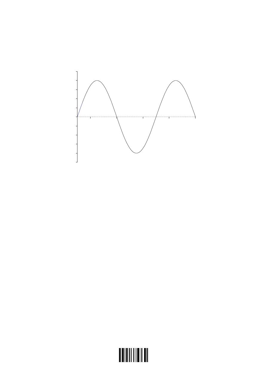
A transverse wave is travelling along a string that is under tension. The diagram below shows
the displacement of part of the string at time
t = 0
. The dotted line shows the position of the
string when there is no wave travelling along it.
displacement / cm
distance along string / cm
5.0
15
25
35
45
(c) On the diagram, draw lines to identify for this wave
(i) the amplitude (label this A).
[1]
(ii) the wavelength (label this
λ
).
[1]
(d) The period of the wave is
1 2 10
3
. ×
−
s
. Deduce that the speed of the wave is
250
1
ms
−
.
. . . . . . . . . . . . . . . . . . . . . . . . . . . . . . . . . . . . . . . . . . . . . . . . . . . . . . . . . . . . . . . . . . . . . .
. . . . . . . . . . . . . . . . . . . . . . . . . . . . . . . . . . . . . . . . . . . . . . . . . . . . . . . . . . . . . . . . . . . . . .
. . . . . . . . . . . . . . . . . . . . . . . . . . . . . . . . . . . . . . . . . . . . . . . . . . . . . . . . . . . . . . . . . . . . . .
. . . . . . . . . . . . . . . . . . . . . . . . . . . . . . . . . . . . . . . . . . . . . . . . . . . . . . . . . . . . . . . . . . . . . .
. . . . . . . . . . . . . . . . . . . . . . . . . . . . . . . . . . . . . . . . . . . . . . . . . . . . . . . . . . . . . . . . . . . . . .
[2]
(This question continues on the following page)
1733
2205-6508
– 18 –
M05/4/PHYSI/HP2/ENG/TZ1/XX+
(Question B2, part 1 continued)
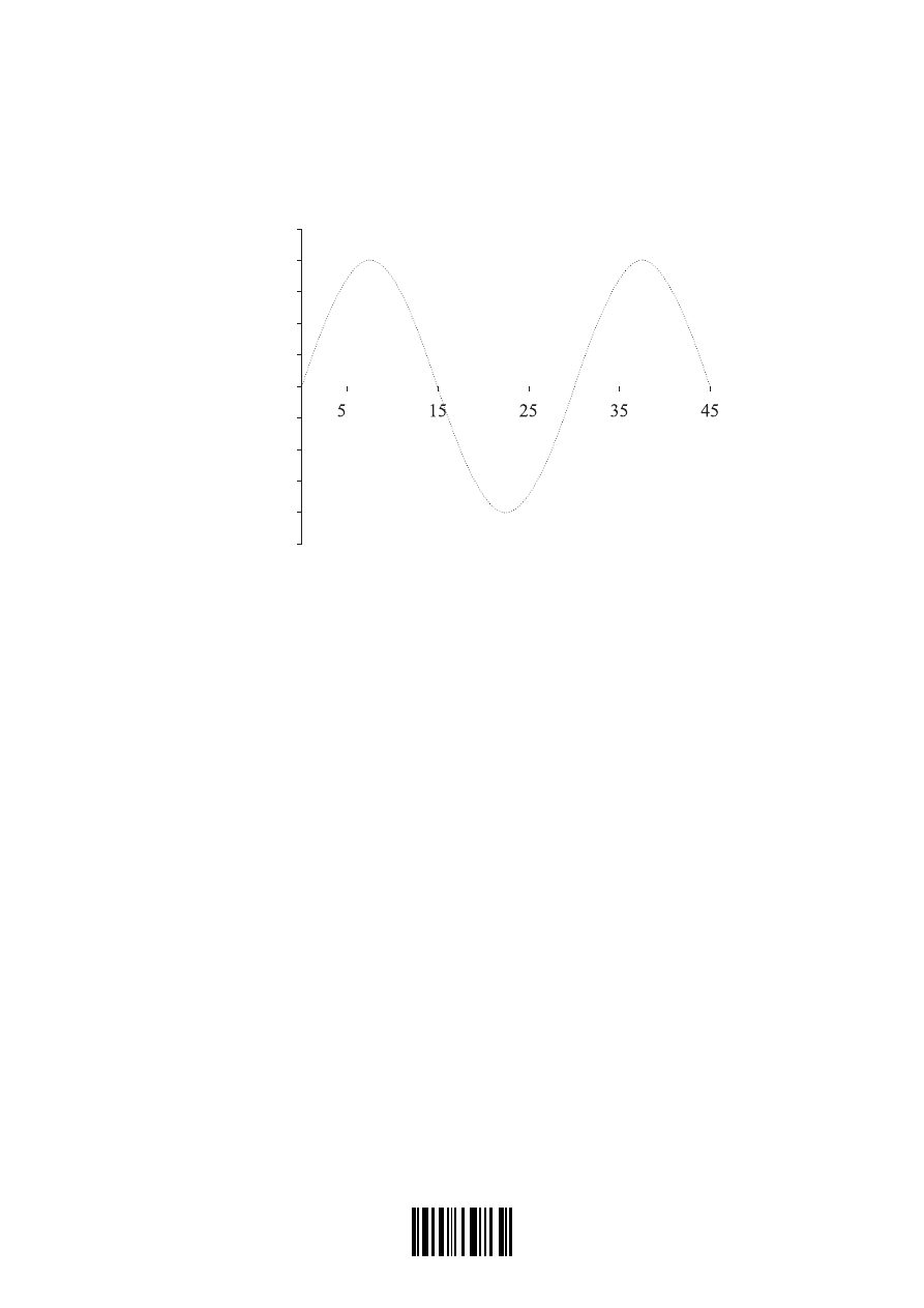
(e) Using the axes below, draw the displacement of the string when
t =
×
−
3 0 10
4
.
s
. (The
displacement of the string at is shown as a dotted line.)
[3]
displacement / cm
distance along string / cm
.0
The string is maintained at the same tension and is adjusted in length to 45 cm. It is made to
resonate at its first harmonic (fundamental) frequency.
(f) Explain what is meant by resonance.
. . . . . . . . . . . . . . . . . . . . . . . . . . . . . . . . . . . . . . . . . . . . . . . . . . . . . . . . . . . . . . . . . . . . . .
. . . . . . . . . . . . . . . . . . . . . . . . . . . . . . . . . . . . . . . . . . . . . . . . . . . . . . . . . . . . . . . . . . . . . .
. . . . . . . . . . . . . . . . . . . . . . . . . . . . . . . . . . . . . . . . . . . . . . . . . . . . . . . . . . . . . . . . . . . . . .
. . . . . . . . . . . . . . . . . . . . . . . . . . . . . . . . . . . . . . . . . . . . . . . . . . . . . . . . . . . . . . . . . . . . . .
[2]
(g) Describe how the string can be made to resonate at its first harmonic frequency only.
. . . . . . . . . . . . . . . . . . . . . . . . . . . . . . . . . . . . . . . . . . . . . . . . . . . . . . . . . . . . . . . . . . . . . .
. . . . . . . . . . . . . . . . . . . . . . . . . . . . . . . . . . . . . . . . . . . . . . . . . . . . . . . . . . . . . . . . . . . . . .
. . . . . . . . . . . . . . . . . . . . . . . . . . . . . . . . . . . . . . . . . . . . . . . . . . . . . . . . . . . . . . . . . . . . . .
. . . . . . . . . . . . . . . . . . . . . . . . . . . . . . . . . . . . . . . . . . . . . . . . . . . . . . . . . . . . . . . . . . . . . .
[2]
(h) Determine the frequency of the first harmonic of the string.
. . . . . . . . . . . . . . . . . . . . . . . . . . . . . . . . . . . . . . . . . . . . . . . . . . . . . . . . . . . . . . . . . . . . . .
. . . . . . . . . . . . . . . . . . . . . . . . . . . . . . . . . . . . . . . . . . . . . . . . . . . . . . . . . . . . . . . . . . . . . .
. . . . . . . . . . . . . . . . . . . . . . . . . . . . . . . . . . . . . . . . . . . . . . . . . . . . . . . . . . . . . . . . . . . . . .
[2]
(This question continues on the following page)
t = 0
1833

2205-6508
– 19 –
Turn over
M05/4/PHYSI/HP2/ENG/TZ1/XX+
(Question B2 continued)
Part 2 The satellite and electrical power generation
(a) Define gravitational field strength.
. . . . . . . . . . . . . . . . . . . . . . . . . . . . . . . . . . . . . . . . . . . . . . . . . . . . . . . . . . . . . . . . . . . . . .
. . . . . . . . . . . . . . . . . . . . . . . . . . . . . . . . . . . . . . . . . . . . . . . . . . . . . . . . . . . . . . . . . . . . . .
. . . . . . . . . . . . . . . . . . . . . . . . . . . . . . . . . . . . . . . . . . . . . . . . . . . . . . . . . . . . . . . . . . . . . .
[2]
(b) Use the definition of gravitational field strength to deduce that
GM g R
=
0
2
where M is the mass of the Earth, R it’s radius and
g
0
is the gravitational field strength
at the surface of the Earth. (You may assume that the Earth is a uniform sphere with its
mass concentrated at its centre.)
. . . . . . . . . . . . . . . . . . . . . . . . . . . . . . . . . . . . . . . . . . . . . . . . . . . . . . . . . . . . . . . . . . . . . .
. . . . . . . . . . . . . . . . . . . . . . . . . . . . . . . . . . . . . . . . . . . . . . . . . . . . . . . . . . . . . . . . . . . . . .
. . . . . . . . . . . . . . . . . . . . . . . . . . . . . . . . . . . . . . . . . . . . . . . . . . . . . . . . . . . . . . . . . . . . . .
. . . . . . . . . . . . . . . . . . . . . . . . . . . . . . . . . . . . . . . . . . . . . . . . . . . . . . . . . . . . . . . . . . . . . .
[2]
(This question continues on the following page)
1933
2205-6508
– 20 –
M05/4/PHYSI/HP2/ENG/TZ1/XX+
(Question B2, part 2 continued)
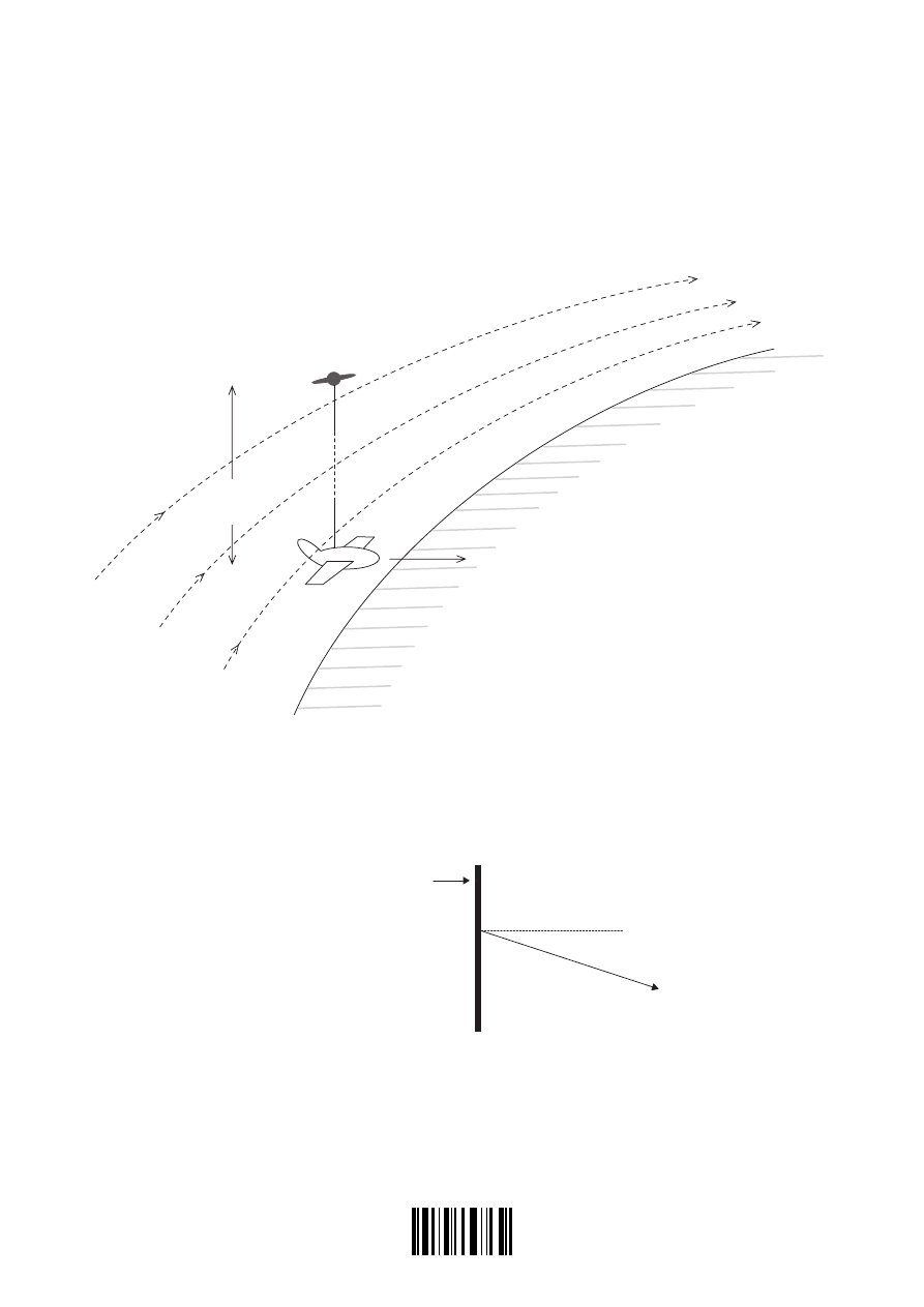
A space shuttle orbits the Earth and a small satellite is launched from the shuttle. The satellite
carries a conducting cable connecting the satellite to the shuttle. When the satellite is a distance
L from the shuttle, the cable is held straight by motors on the satellite.
Diagram 1
Earth’s magnetic field
satellite
conducting cable
L
shuttle
direction of orbit
speed v
EARTH
As the shuttle orbits the Earth with speed v, the conducting cable is moving at right angles to the
Earth’s magnetic field. The magnetic field vector B makes an angle
θ
to a line perpendicular to
the conducting cable as shown in diagram 2. The velocity vector of the shuttle is directed out
of the plane of the paper.
Diagram 2
conducting cable
θ
B
(c) On diagram 2, draw an arrow to show the direction of the magnetic force on an electron
in the conducting cable. Label the arrow F.
[1]
(This question continues on the following page)
2033

2205-6508
– 21 –
Turn over
M05/4/PHYSI/HP2/ENG/TZ1/XX+
(Question B2, part 2 continued)
(d) State an expression for the force F on the electron in terms of B, v, e and
θ
, where B is the
magnitude of the magnetic field strength and e is the electron charge.
. . . . . . . . . . . . . . . . . . . . . . . . . . . . . . . . . . . . . . . . . . . . . . . . . . . . . . . . . . . . . . . . . . . . . .
[1]
(e) Hence deduce an expression for the e.m.f. E induced in the conducting wire.
. . . . . . . . . . . . . . . . . . . . . . . . . . . . . . . . . . . . . . . . . . . . . . . . . . . . . . . . . . . . . . . . . . . . . .
. . . . . . . . . . . . . . . . . . . . . . . . . . . . . . . . . . . . . . . . . . . . . . . . . . . . . . . . . . . . . . . . . . . . . .
. . . . . . . . . . . . . . . . . . . . . . . . . . . . . . . . . . . . . . . . . . . . . . . . . . . . . . . . . . . . . . . . . . . . . .
. . . . . . . . . . . . . . . . . . . . . . . . . . . . . . . . . . . . . . . . . . . . . . . . . . . . . . . . . . . . . . . . . . . . . .
. . . . . . . . . . . . . . . . . . . . . . . . . . . . . . . . . . . . . . . . . . . . . . . . . . . . . . . . . . . . . . . . . . . . . .
[3]
(f) The shuttle is in an orbit that is 300 km above the surface of the Earth. Using the
expression
GM g R
=
0
2
and given that
R =
×
6 4 10
6
.
m
and
g
0
1
10
=
−
N kg
, deduce that the orbital speed v of the
satellite is
7 8 10
3
. ×
ms
-1
.
. . . . . . . . . . . . . . . . . . . . . . . . . . . . . . . . . . . . . . . . . . . . . . . . . . . . . . . . . . . . . . . . . . . . . .
. . . . . . . . . . . . . . . . . . . . . . . . . . . . . . . . . . . . . . . . . . . . . . . . . . . . . . . . . . . . . . . . . . . . . .
. . . . . . . . . . . . . . . . . . . . . . . . . . . . . . . . . . . . . . . . . . . . . . . . . . . . . . . . . . . . . . . . . . . . . .
. . . . . . . . . . . . . . . . . . . . . . . . . . . . . . . . . . . . . . . . . . . . . . . . . . . . . . . . . . . . . . . . . . . . . .
. . . . . . . . . . . . . . . . . . . . . . . . . . . . . . . . . . . . . . . . . . . . . . . . . . . . . . . . . . . . . . . . . . . . . .
. . . . . . . . . . . . . . . . . . . . . . . . . . . . . . . . . . . . . . . . . . . . . . . . . . . . . . . . . . . . . . . . . . . . . .
. . . . . . . . . . . . . . . . . . . . . . . . . . . . . . . . . . . . . . . . . . . . . . . . . . . . . . . . . . . . . . . . . . . . . .
[3]
(g) The magnitude of the magnetic field strength is
6 3 10
6
. ×
−
T
and the angle
θ = 20
o
.
Estimate the length L of the cable required in order to generate an e.m.f. of
1 kV
.
. . . . . . . . . . . . . . . . . . . . . . . . . . . . . . . . . . . . . . . . . . . . . . . . . . . . . . . . . . . . . . . . . . . . . .
. . . . . . . . . . . . . . . . . . . . . . . . . . . . . . . . . . . . . . . . . . . . . . . . . . . . . . . . . . . . . . . . . . . . . .
. . . . . . . . . . . . . . . . . . . . . . . . . . . . . . . . . . . . . . . . . . . . . . . . . . . . . . . . . . . . . . . . . . . . . .
[2]
2133

2205-6508
– 22 –
M05/4/PHYSI/HP2/ENG/TZ1/XX+
Blank page
2233
2205-6508
– 23 –
Turn over
M05/4/PHYSI/HP2/ENG/TZ1/XX+
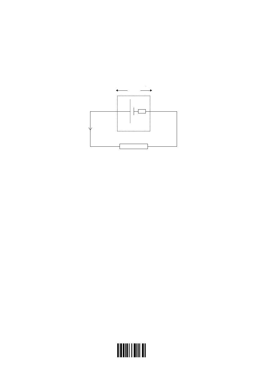
B3. This question is in two parts. Part 1 is about e.m.f. and internal resistance. Part 2 is about the
wave properties of light and electrons.
Part 1 e.m.f. and internal resistance
A dry cell has an e.m.f. E and internal resistance r and is connected to an external circuit. There
is a current I in the circuit when the potential difference across the terminals of the cell is V.
V
r
I
E
(a) State expressions, in terms of E, V, r and I where appropriate, for
(i) the total power supplied by the cell.
. . . . . . . . . . . . . . . . . . . . . . . . . . . . . . . . . . . . . . . . . . . . . . . . . . . . . . . . . . . . . . . . .
[1]
(ii) the power dissipated in the cell.
. . . . . . . . . . . . . . . . . . . . . . . . . . . . . . . . . . . . . . . . . . . . . . . . . . . . . . . . . . . . . . . . .
[1]
(iii) the power dissipated in the external circuit.
. . . . . . . . . . . . . . . . . . . . . . . . . . . . . . . . . . . . . . . . . . . . . . . . . . . . . . . . . . . . . . . . .
[1]
(b) Use your answers to (a) to derive a relationship between V, E, I and r.
. . . . . . . . . . . . . . . . . . . . . . . . . . . . . . . . . . . . . . . . . . . . . . . . . . . . . . . . . . . . . . . . . . . . . .
. . . . . . . . . . . . . . . . . . . . . . . . . . . . . . . . . . . . . . . . . . . . . . . . . . . . . . . . . . . . . . . . . . . . . .
. . . . . . . . . . . . . . . . . . . . . . . . . . . . . . . . . . . . . . . . . . . . . . . . . . . . . . . . . . . . . . . . . . . . . .
[2]
(This question continues on the following page)
2333
2205-6508
– 24 –
M05/4/PHYSI/HP2/ENG/TZ1/XX+
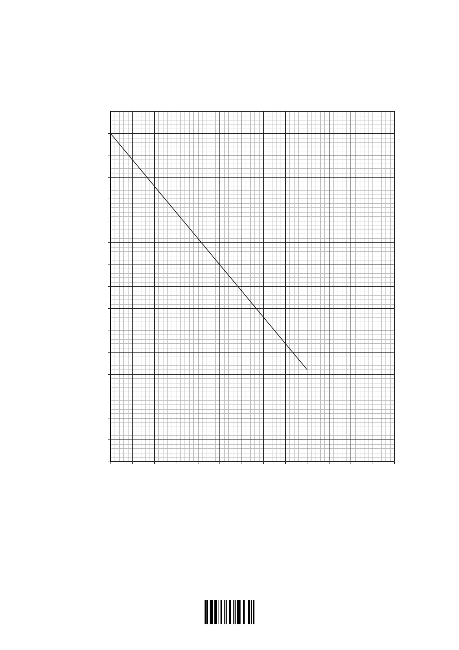
(Question B3, part 1 continued)
The graph below shows the variation of V with I for the dry cell.
V / V
0.0 0.10 0.20 0.30 0.40 0.50 0.60 0.70 0.80 0.90 1.0 1.1 1.2 1.3
0.0
0.10
0.20
0.30
0.40
0.50
0.60
0.70
0.80
0.90
1.0
1.1
1.2
1.3
1.4
1.5
1.6
I / A
(This question continues on the following page)
2433

2205-6508
– 25 –
Turn over
M05/4/PHYSI/HP2/ENG/TZ1/XX+
(Question B3, part 1 continued)
(c) Complete the diagram below to show the circuit that could be used to obtain the data from
which the graph was plotted.
[3]
(d) Use the graph, explaining your answers, to
(i) determine the e.m.f. E of the cell.
. . . . . . . . . . . . . . . . . . . . . . . . . . . . . . . . . . . . . . . . . . . . . . . . . . . . . . . . . . . . . . . . .
. . . . . . . . . . . . . . . . . . . . . . . . . . . . . . . . . . . . . . . . . . . . . . . . . . . . . . . . . . . . . . . . .
[2]
(ii) determine the current in the external circuit when the resistance R of the external
circuit is very small.
. . . . . . . . . . . . . . . . . . . . . . . . . . . . . . . . . . . . . . . . . . . . . . . . . . . . . . . . . . . . . . . . .
. . . . . . . . . . . . . . . . . . . . . . . . . . . . . . . . . . . . . . . . . . . . . . . . . . . . . . . . . . . . . . . . .
. . . . . . . . . . . . . . . . . . . . . . . . . . . . . . . . . . . . . . . . . . . . . . . . . . . . . . . . . . . . . . . . .
. . . . . . . . . . . . . . . . . . . . . . . . . . . . . . . . . . . . . . . . . . . . . . . . . . . . . . . . . . . . . . . . .
[2]
(iii) deduce that the internal resistance r of the cell is about 1.2
1 2
. Ω
.
. . . . . . . . . . . . . . . . . . . . . . . . . . . . . . . . . . . . . . . . . . . . . . . . . . . . . . . . . . . . . . . . .
. . . . . . . . . . . . . . . . . . . . . . . . . . . . . . . . . . . . . . . . . . . . . . . . . . . . . . . . . . . . . . . . .
. . . . . . . . . . . . . . . . . . . . . . . . . . . . . . . . . . . . . . . . . . . . . . . . . . . . . . . . . . . . . . . . .
. . . . . . . . . . . . . . . . . . . . . . . . . . . . . . . . . . . . . . . . . . . . . . . . . . . . . . . . . . . . . . . . .
. . . . . . . . . . . . . . . . . . . . . . . . . . . . . . . . . . . . . . . . . . . . . . . . . . . . . . . . . . . . . . . . .
[3]
(This question continues on the following page)
2533

2205-6508
– 26 –
M05/4/PHYSI/HP2/ENG/TZ1/XX+
(Question B3, part 1 continued)
(e) The maximum power dissipated in the external circuit occurs when the resistance of the
external circuit has the same value as the internal resistance of the cell. Calculate the
maximum power dissipation in the external circuit.
. . . . . . . . . . . . . . . . . . . . . . . . . . . . . . . . . . . . . . . . . . . . . . . . . . . . . . . . . . . . . . . . . . . . . .
. . . . . . . . . . . . . . . . . . . . . . . . . . . . . . . . . . . . . . . . . . . . . . . . . . . . . . . . . . . . . . . . . . . . . .
. . . . . . . . . . . . . . . . . . . . . . . . . . . . . . . . . . . . . . . . . . . . . . . . . . . . . . . . . . . . . . . . . . . . . .
. . . . . . . . . . . . . . . . . . . . . . . . . . . . . . . . . . . . . . . . . . . . . . . . . . . . . . . . . . . . . . . . . . . . . .
[3]
(This question continues on page 28)
2633

2205-6508
– 27 –
Turn over
M05/4/PHYSI/HP2/ENG/TZ1/XX+
Blank page
2733
2205-6508
– 28 –
M05/4/PHYSI/HP2/ENG/TZ1/XX+
(Question B3 continued)
Part 2 Light and electrons
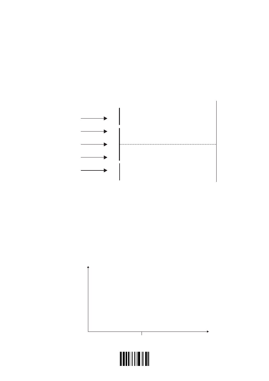
The diagram below (not to scale) is an arrangement for observing the interference pattern
produced on a screen when the light from two narrow slits
S
1
and
S
2
overlaps. A beam of light
from a laser is incident on the slits and after passing through the slits, the light is incident on
a screen. The separation between the slits is large compared to the width of the slits and the
distance between the slits and the screen is large compared to the slit separation.
The point X on the screen is equidistant from
S
1
and
S
2
.
light from laser
screen
double slit
S
1
X
S
2
(a) Explain why an interference pattern will not be observed on the screen if the laser is
replaced with a tungsten filament lamp.
. . . . . . . . . . . . . . . . . . . . . . . . . . . . . . . . . . . . . . . . . . . . . . . . . . . . . . . . . . . . . . . . . . . . . .
. . . . . . . . . . . . . . . . . . . . . . . . . . . . . . . . . . . . . . . . . . . . . . . . . . . . . . . . . . . . . . . . . . . . . .
. . . . . . . . . . . . . . . . . . . . . . . . . . . . . . . . . . . . . . . . . . . . . . . . . . . . . . . . . . . . . . . . . . . . . .
. . . . . . . . . . . . . . . . . . . . . . . . . . . . . . . . . . . . . . . . . . . . . . . . . . . . . . . . . . . . . . . . . . . . . .
[2]
(b) On the axes below, draw a sketch-graph to show how the intensity of the observed
interference pattern varies with distance along the screen.
[2]
intensity /
arbitrary units
X
distance along screen
(This question continues on the following page)
2833

2205-6508
– 29 –
Turn over
M05/4/PHYSI/HP2/ENG/TZ1/XX+
(Question B3, part 2 continued)
(c) The wavelength of the light from the laser is 633 nm and the angular separation of the
bright fringes on the screen is
4 00 10
4
. ×
−
rad. Calculate the distance between
S
1
and
S
2
.
. . . . . . . . . . . . . . . . . . . . . . . . . . . . . . . . . . . . . . . . . . . . . . . . . . . . . . . . . . . . . . . . . . . . . .
. . . . . . . . . . . . . . . . . . . . . . . . . . . . . . . . . . . . . . . . . . . . . . . . . . . . . . . . . . . . . . . . . . . . . .
. . . . . . . . . . . . . . . . . . . . . . . . . . . . . . . . . . . . . . . . . . . . . . . . . . . . . . . . . . . . . . . . . . . . . .
. . . . . . . . . . . . . . . . . . . . . . . . . . . . . . . . . . . . . . . . . . . . . . . . . . . . . . . . . . . . . . . . . . . . . .
. . . . . . . . . . . . . . . . . . . . . . . . . . . . . . . . . . . . . . . . . . . . . . . . . . . . . . . . . . . . . . . . . . . . . .
[3]
(d) Consider now a “thought” experiment in which the light from the laser is replaced by a
beam of electrons that has been accelerated from rest through a potential difference V.
Deduce that the de Broglie wavelength
λ
of the electrons is
λ =
h
m Ve
e
2
where h is the Planck constant,
m
e
the electron mass and e the electron charge.
. . . . . . . . . . . . . . . . . . . . . . . . . . . . . . . . . . . . . . . . . . . . . . . . . . . . . . . . . . . . . . . . . . . . . .
. . . . . . . . . . . . . . . . . . . . . . . . . . . . . . . . . . . . . . . . . . . . . . . . . . . . . . . . . . . . . . . . . . . . . .
. . . . . . . . . . . . . . . . . . . . . . . . . . . . . . . . . . . . . . . . . . . . . . . . . . . . . . . . . . . . . . . . . . . . . .
. . . . . . . . . . . . . . . . . . . . . . . . . . . . . . . . . . . . . . . . . . . . . . . . . . . . . . . . . . . . . . . . . . . . . .
. . . . . . . . . . . . . . . . . . . . . . . . . . . . . . . . . . . . . . . . . . . . . . . . . . . . . . . . . . . . . . . . . . . . . .
. . . . . . . . . . . . . . . . . . . . . . . . . . . . . . . . . . . . . . . . . . . . . . . . . . . . . . . . . . . . . . . . . . . . . .
[3]
(e) The electron beam is accelerated from rest through a potential difference of 400 V.
Calculate the separation of
S
1
and
S
2
such that the angular separation of the electron
interference fringes is
4 00 10
4
. ×
−
rad.
. . . . . . . . . . . . . . . . . . . . . . . . . . . . . . . . . . . . . . . . . . . . . . . . . . . . . . . . . . . . . . . . . . . . . .
. . . . . . . . . . . . . . . . . . . . . . . . . . . . . . . . . . . . . . . . . . . . . . . . . . . . . . . . . . . . . . . . . . . . . .
. . . . . . . . . . . . . . . . . . . . . . . . . . . . . . . . . . . . . . . . . . . . . . . . . . . . . . . . . . . . . . . . . . . . . .
. . . . . . . . . . . . . . . . . . . . . . . . . . . . . . . . . . . . . . . . . . . . . . . . . . . . . . . . . . . . . . . . . . . . . .
[2]
2933
2205-6508
– 30 –
M05/4/PHYSI/HP2/ENG/TZ1/XX+
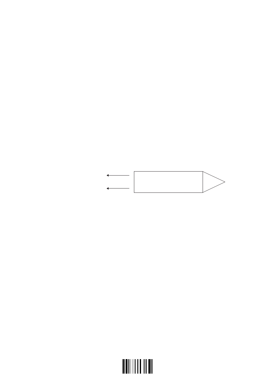
B4. This question is in two parts. Part 1 is about driving a metal bar into the ground and the engine
used in the process. Part 2 is about the force between current-carrying wires.
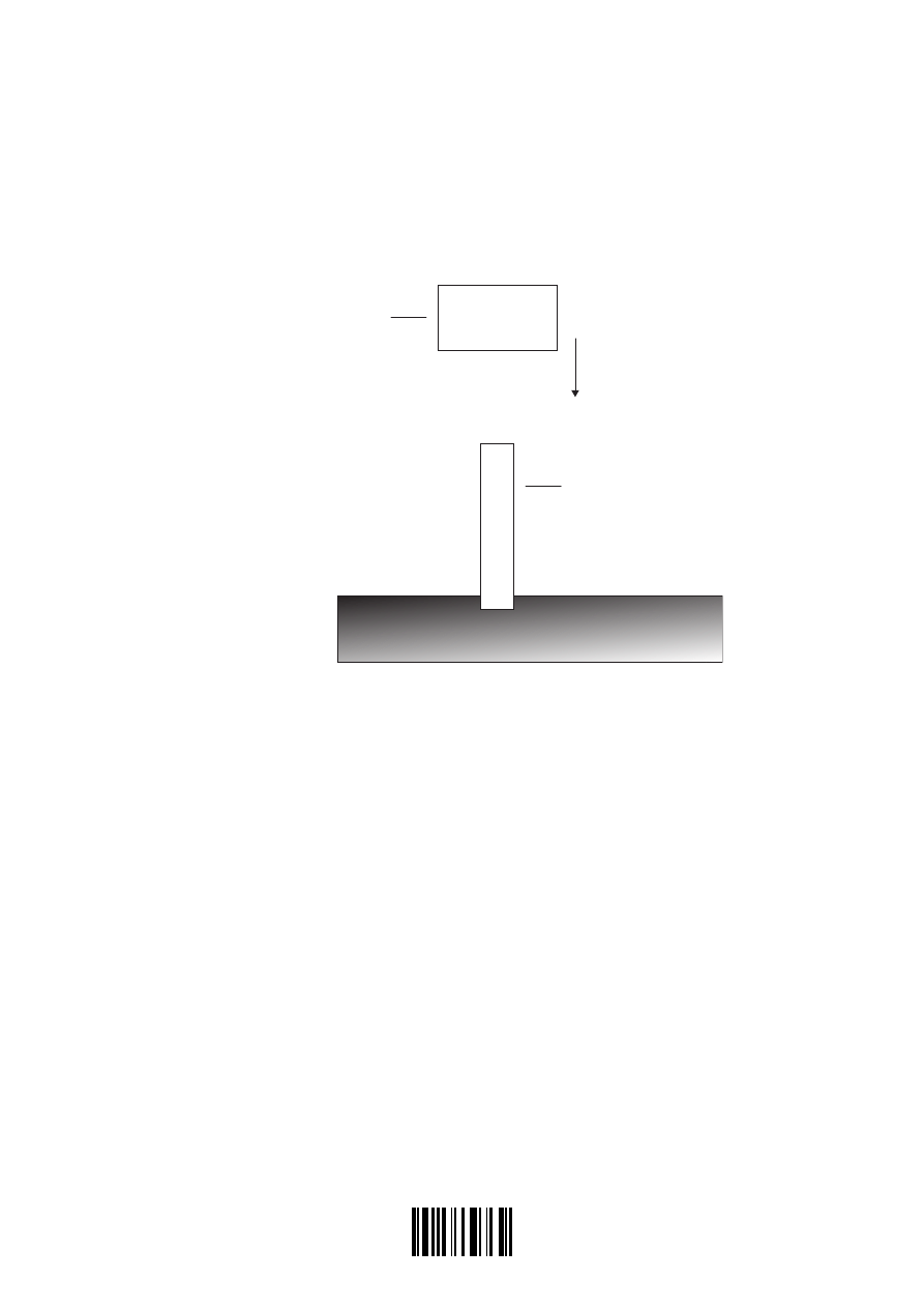
Part 1 The metal bar
Large metal bars can be driven into the ground using a heavy falling object.
object mass =
2 0 10
3
. ×
kg
bar mass = 400 kg
In the situation shown, the object has a mass
2 0 10
3
. ×
kg
and the metal bar has a mass of 400 kg.
The object strikes the bar at a speed of
6 0
1
. ms
−
. It comes to rest on the bar without bouncing.
As a result of the collision, the bar is driven into the ground to a depth of 0.75 m.
(a) Determine the speed of the bar immediately after the object strikes it.
. . . . . . . . . . . . . . . . . . . . . . . . . . . . . . . . . . . . . . . . . . . . . . . . . . . . . . . . . . . . . . . . . . . . . .
. . . . . . . . . . . . . . . . . . . . . . . . . . . . . . . . . . . . . . . . . . . . . . . . . . . . . . . . . . . . . . . . . . . . . .
. . . . . . . . . . . . . . . . . . . . . . . . . . . . . . . . . . . . . . . . . . . . . . . . . . . . . . . . . . . . . . . . . . . . . .
. . . . . . . . . . . . . . . . . . . . . . . . . . . . . . . . . . . . . . . . . . . . . . . . . . . . . . . . . . . . . . . . . . . . . .
. . . . . . . . . . . . . . . . . . . . . . . . . . . . . . . . . . . . . . . . . . . . . . . . . . . . . . . . . . . . . . . . . . . . . .
. . . . . . . . . . . . . . . . . . . . . . . . . . . . . . . . . . . . . . . . . . . . . . . . . . . . . . . . . . . . . . . . . . . . . .
[4]
(This question continues on the following page)
3033

2205-6508
– 31 –
Turn over
M05/4/PHYSI/HP2/ENG/TZ1/XX+
(Question B4, part 1 continued)
(b) Determine the average frictional force exerted by the ground on the bar.
. . . . . . . . . . . . . . . . . . . . . . . . . . . . . . . . . . . . . . . . . . . . . . . . . . . . . . . . . . . . . . . . . . . . . .
. . . . . . . . . . . . . . . . . . . . . . . . . . . . . . . . . . . . . . . . . . . . . . . . . . . . . . . . . . . . . . . . . . . . . .
. . . . . . . . . . . . . . . . . . . . . . . . . . . . . . . . . . . . . . . . . . . . . . . . . . . . . . . . . . . . . . . . . . . . . .
. . . . . . . . . . . . . . . . . . . . . . . . . . . . . . . . . . . . . . . . . . . . . . . . . . . . . . . . . . . . . . . . . . . . . .
. . . . . . . . . . . . . . . . . . . . . . . . . . . . . . . . . . . . . . . . . . . . . . . . . . . . . . . . . . . . . . . . . . . . . .
[3]
(c) The object is raised by a diesel engine that has a useful power output of
7.2 kW
.
In order that the falling object strikes the bar at a speed of
6 0
1
. ms
−
, it must be raised to
a certain height above the bar. Assuming that there are no energy losses due to friction,
calculate how long it takes the engine to raise the object to this height.
. . . . . . . . . . . . . . . . . . . . . . . . . . . . . . . . . . . . . . . . . . . . . . . . . . . . . . . . . . . . . . . . . . . . . .
. . . . . . . . . . . . . . . . . . . . . . . . . . . . . . . . . . . . . . . . . . . . . . . . . . . . . . . . . . . . . . . . . . . . . .
. . . . . . . . . . . . . . . . . . . . . . . . . . . . . . . . . . . . . . . . . . . . . . . . . . . . . . . . . . . . . . . . . . . . . .
. . . . . . . . . . . . . . . . . . . . . . . . . . . . . . . . . . . . . . . . . . . . . . . . . . . . . . . . . . . . . . . . . . . . . .
. . . . . . . . . . . . . . . . . . . . . . . . . . . . . . . . . . . . . . . . . . . . . . . . . . . . . . . . . . . . . . . . . . . . . .
. . . . . . . . . . . . . . . . . . . . . . . . . . . . . . . . . . . . . . . . . . . . . . . . . . . . . . . . . . . . . . . . . . . . . .
[4]
(This question continues on the following page)
3133
2205-6508
– 32 –
M05/4/PHYSI/HP2/ENG/TZ1/XX+
(Question B4, part 1 continued)
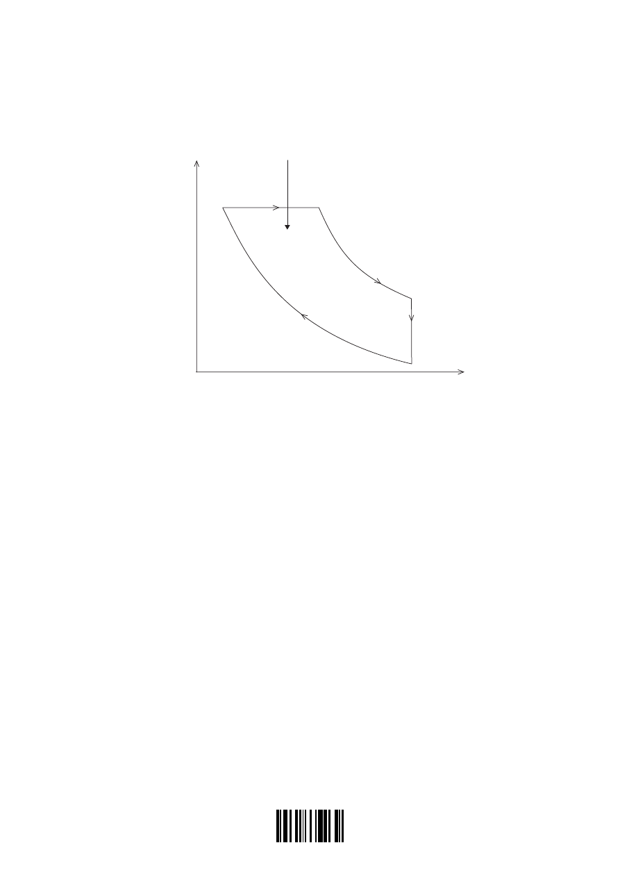
The diagram below shows the relation between the pressure and the volume of the air in the
diesel engine for one cycle of operation of the engine. During the cycle there are two adiabatic
processes, an isochoric process and an isobaric process.
pressure
thermal energy
B
C
D
A
volume
(d) Explain what is meant by
(i) an adiabatic process.
. . . . . . . . . . . . . . . . . . . . . . . . . . . . . . . . . . . . . . . . . . . . . . . . . . . . . . . . . . . . . . . . .
. . . . . . . . . . . . . . . . . . . . . . . . . . . . . . . . . . . . . . . . . . . . . . . . . . . . . . . . . . . . . . . . .
. . . . . . . . . . . . . . . . . . . . . . . . . . . . . . . . . . . . . . . . . . . . . . . . . . . . . . . . . . . . . . . . .
[2]
(ii) an isochoric process.
. . . . . . . . . . . . . . . . . . . . . . . . . . . . . . . . . . . . . . . . . . . . . . . . . . . . . . . . . . . . . . . . .
. . . . . . . . . . . . . . . . . . . . . . . . . . . . . . . . . . . . . . . . . . . . . . . . . . . . . . . . . . . . . . . . .
[1]
(iii) an isobaric process.
. . . . . . . . . . . . . . . . . . . . . . . . . . . . . . . . . . . . . . . . . . . . . . . . . . . . . . . . . . . . . . . . .
. . . . . . . . . . . . . . . . . . . . . . . . . . . . . . . . . . . . . . . . . . . . . . . . . . . . . . . . . . . . . . . . .
[1]
(This question continues on the following page)
3233

2205-6508
– 33 –
Turn over
M05/4/PHYSI/HP2/ENG/TZ1/XX+
(Question B4, part 1 continued)
(e) Identify, from the diagram, the following processes.
(i) Adiabatic processes
. . . . . . . . . . . . . . . . . . . . . . . . . . . . . . . . . . . . . . . . . . . . . . . . . . . . . . . . . . . . . . . . .
[1]
(ii) Isochoric process
. . . . . . . . . . . . . . . . . . . . . . . . . . . . . . . . . . . . . . . . . . . . . . . . . . . . . . . . . . . . . . . . .
[1]
(iii) Isobaric process
. . . . . . . . . . . . . . . . . . . . . . . . . . . . . . . . . . . . . . . . . . . . . . . . . . . . . . . . . . . . . . . . .
[1]
During the process
B
C
→
thermal energy is absorbed.
The diesel engine has a total power output of 8.4 kW and an efficiency of 40 %. The cycle of
operation is repeated 40 times every second.
(f) State what quantity is represented on the diagram by the area ABCD.
. . . . . . . . . . . . . . . . . . . . . . . . . . . . . . . . . . . . . . . . . . . . . . . . . . . . . . . . . . . . . . . . . . . . . .
[1]
(g) Determine the value of the quantity that is represented by the area ABCD.
. . . . . . . . . . . . . . . . . . . . . . . . . . . . . . . . . . . . . . . . . . . . . . . . . . . . . . . . . . . . . . . . . . . . . .
. . . . . . . . . . . . . . . . . . . . . . . . . . . . . . . . . . . . . . . . . . . . . . . . . . . . . . . . . . . . . . . . . . . . . .
[1]
(h) Determine the thermal energy absorbed during the process
B
C
→
.
. . . . . . . . . . . . . . . . . . . . . . . . . . . . . . . . . . . . . . . . . . . . . . . . . . . . . . . . . . . . . . . . . . . . . .
. . . . . . . . . . . . . . . . . . . . . . . . . . . . . . . . . . . . . . . . . . . . . . . . . . . . . . . . . . . . . . . . . . . . . .
. . . . . . . . . . . . . . . . . . . . . . . . . . . . . . . . . . . . . . . . . . . . . . . . . . . . . . . . . . . . . . . . . . . . . .
. . . . . . . . . . . . . . . . . . . . . . . . . . . . . . . . . . . . . . . . . . . . . . . . . . . . . . . . . . . . . . . . . . . . . .
[2]
(This question continues on the following page)
3333
2205-6508
– 34 –
M05/4/PHYSI/HP2/ENG/TZ1/XX+
(Question B4 continued)
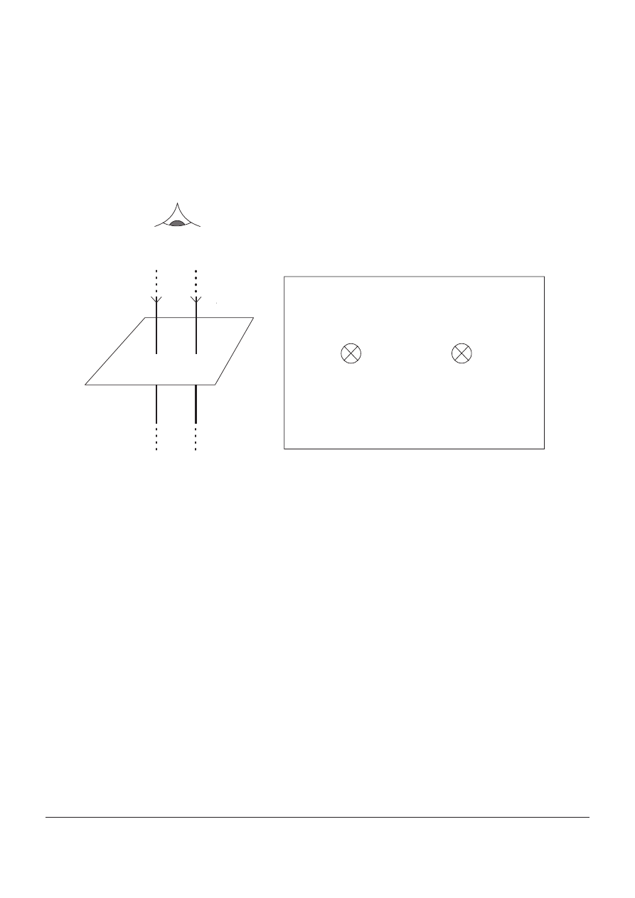
Part 2 Force between current-carrying wires
Diagram 1 below shows two long, parallel vertical wires each carrying equal currents in the
same direction. The wires pass through a horizontal sheet of card. Diagram 2 shows a plan
view of the wires looking down onto the card.
eye
sheet of card
Diagram 1
Diagram 2
(a) Draw on diagram 2 the magnetic field pattern due to the currents in the wire.
[3]
(b) Outline how two current carrying conductors may be used to define the ampere.
. . . . . . . . . . . . . . . . . . . . . . . . . . . . . . . . . . . . . . . . . . . . . . . . . . . . . . . . . . . . . . . . . . . . . .
. . . . . . . . . . . . . . . . . . . . . . . . . . . . . . . . . . . . . . . . . . . . . . . . . . . . . . . . . . . . . . . . . . . . . .
. . . . . . . . . . . . . . . . . . . . . . . . . . . . . . . . . . . . . . . . . . . . . . . . . . . . . . . . . . . . . . . . . . . . . .
[2]
(c) The card is removed and one of the two wires is free to move. Describe and explain, the
changes in the velocity and in acceleration of the moveable wire.
. . . . . . . . . . . . . . . . . . . . . . . . . . . . . . . . . . . . . . . . . . . . . . . . . . . . . . . . . . . . . . . . . . . . . .
. . . . . . . . . . . . . . . . . . . . . . . . . . . . . . . . . . . . . . . . . . . . . . . . . . . . . . . . . . . . . . . . . . . . . .
. . . . . . . . . . . . . . . . . . . . . . . . . . . . . . . . . . . . . . . . . . . . . . . . . . . . . . . . . . . . . . . . . . . . . .
. . . . . . . . . . . . . . . . . . . . . . . . . . . . . . . . . . . . . . . . . . . . . . . . . . . . . . . . . . . . . . . . . . . . . .
. . . . . . . . . . . . . . . . . . . . . . . . . . . . . . . . . . . . . . . . . . . . . . . . . . . . . . . . . . . . . . . . . . . . . .
[3]
Wyszukiwarka
Podobne podstrony:
PhysHL P2 M05 TZ1 M
PhysHL P3 M05 TZ1 M
PhysHL P2 M05 TZ2 M
PhysHL P2 M04 TZ1
PhysHL P3 M05 TZ1
PhysHL P1 M05 TZ1
PhysHL P1 M05 TZ1 M
PhysHL P2 M05 TZ2
PhysHL P2 M06 TZ1
PhysHL P3 M05 TZ1 M
PhysHL P2 M00
PhysHL P2 M03
PhysHL P2 M04 TZ2 M
PhysHL P1 M06 TZ1
PhysHL P2 N06 TZ0 MS
PhysHL P2 N04 TZ0 M
PhysHL P3 M06 TZ1
PhysHL P2 M06 TZ2 M
więcej podobnych podstron