Hepworth Heating Ltd.,
Nottingham Road, Belper, Derbyshire. DE56 1JT
General/Sales enquiries:
Tel: (01773) 824141 Fax: (01773) 820569
One Contact Local Service
Customer Services:
Tel: (01773) 828100
Fax: (01773) 828070
221917C.06.02
All replacement parts
All labour charges
All call-out charges
Guarantee Registration
Miami GF
Radiant Convector Gas Fire
This is a Cat I
2H
Appliance
Reference in these instructions to British Standards and Statutory
Regulations/Requirements apply only to the United Kingdom.
For Ireland the rules in force must be used.
The instructions consist of three parts, User, Installation and Servicing Instructions, which includes the Guarantee Registration
Card. The instructions are an integral part of the appliance and must, to comply with the current issue of the Gas Safety
(Installation and Use) Regulations, be handed to the user on completion of the installation.
T o b e l e f t w i t h t h e u s e r
❏
✔
❏
✔
❏
✔
Instructions for Use
Installation and Servicing
G.C. No. 32- 047- 05
REGISTER YOUR GLOW-WORM APPLIANCE
FOR 1ST YEAR GUARANTEE PROTECTION
CALL 0208 247 9857
Thank you for installing a new Glow-worm appliance in your home.
Glow-worm appliances' are manufactured to the very highest standard so we are pleased to offer our customers'
a Comprehensive First Year Guarantee.
In the center pages are to be found your Guarantee Registration Card, which we recommend you complete and
return as soon as possible.
If this card is missing you can obtain a copy or record your registration by telephoning the Heatcall Customer
Service number 01773 828100.
Our Guarantee gives you peace of mind plus valuable protection against breakdown by covering the cost of:
9418

2
221917C
CONTENTS
DESCRIPTION
SECTION
PAGE No.
Certification
This fire is certificated to the current issue of BS6332 part 2, invoking the current issue of BS5258 part 5 for safety and performance.
It is, therefore, important that no alteration is made to the fire, without permission, in writing, from Hepworth Heating Ltd.
Any alteration that is not approved by Hepworth Heating Ltd., could invalidate the certification, the warranty and could infringe the
statutory requirements.
CE Mark
The CE mark on this appliance shows compliance with:
1. Directive 90/396/EEC on the approximation of the Laws of the Member States relating to appliances burning gaseous fuels.
2. Directive 89/336/EEC on the harmonization of the Laws of the Member States relating to electromagnetic compatibility.
INFORMATION FOR THE INSTALLER AND SERVICE ENGINEER.
Under Section 6 of the Health and Safety at Work Act 1974, we are required to provide information on substances hazardous to health.
The Adhesives and sealants used in this appliance are cured and give no known hazard in this state.
RADIANTS
After handling wash hands thoroughly.
INSULATION PADS/CERAMIC FIBRE, GLASSYARN, MINERAL WOOL
These can cause irritation to skin, eyes and the respiratory tract.
If you have a history of skin complaint you may be susceptible to irritation. High dust levels are usual only if the material is broken.
Normal handling should not cause discomfort, but follow normal good hygiene and wash your hands before eating, drinking or going
to the lavatory.
If you do suffer irritation to the eyes or severe irritation to the skin seek medical attention.
Safety
3
Operating your Fire
4
Cleaning
5
Replacing Radiants
5
Maintenace
5
Installation Requirements
1
6
Pre-Installation Preparation
2
9
Closure Plate Installation
3
10
Appliance Installation
4
11
Control & Pressure Checks
5
12
Outer Case Fitting
6
12
Spillage Check
7
13
Final Review
8
13
Servicing & Parts Replacement
9
14
Fault Finding
10
16
INSTRUCTIONS
FOR USE
INSTALLATION
INSTRUCTIONS
SERVICING
INSTRUCTIONS
Important Information
SERVICING
REMEMBER, When replacing a part on this appliance, use only spare parts that you can be assured conform to the safety and
performance specification that we require. Do not use reconditioned or copy parts that have not been clearly authorised by Hepworth
Heating Ltd.

3
221917C
Instructions for Use
IF YOU SMELL GAS
DON’T SMOKE
EXTINGUISH ALL NAKED FLAMES
DON’T TURN ELECTRICAL SWITCHES ON OR OFF
TURN OFF THE GAS SUPPLY AT THE METER
OPEN DOORS AND WINDOWS TO GET RID OF THE GAS
IMMEDIATELY CALL THE GAS EMERGENCY SERVICE - SEE YOUR LOCAL TELEPHONE
DIRECTORY
For your Safety
Have the fire installed by a competent person. In the United
Kingdom, installation must be in accordance with the latest
edition of the Gas Safety (installation & use) Regulations. In the
Republic of Ireland, installation must be in accordance with all
national and local regulations in force.
Have the chimney swept prior to installation if it was previously
used for solid fuel.
Have the fire installed in accordance with the installation
instructions
Allow a minimum clearance of 110mm from the top of the
appliance case to the underside of any shelf whether it is made
from combustible or non-combustible materials. This clearance
is necessary to allow the case to be lifted off for servicing and
also allows sufficient access to operate the control knob. For a
shelf made from wood or other combustible materials deeper
than 150mm add 12.5mm to this clearance for every 25mm of
shelf depth over 150mm. Please bear this in mind if ever you
add a shelf.
Provide a suitable guard which complies with BS 6539 or 6778
for the protection of young children, the elderly and the infirm.
Such a guard is also recommended for the protection of pet
animals. (Although this fire conforms to all the applicable
standards, it is a heating appliance and certain parts of its
surface will become hot.)
Note: The guard supplied with the fire acts as a fireguard
conforming to BS1945:1971 and satisfies the Heating Appliance
(Fireguard) (Safety) Regulations 1991.
Always wait three minutes before attempting to relight if the fire
is switched off or the flames are extinguished for any reason.
(Your fire is fitted with a safety device which will automatically
shut off the gas supply to the fire if, for any reason, the flames
go out.)
Get advice about the suitability of any wall covering near your
fire. Soft wall coverings (e.g. embossed vinyl, etc.) which have
a raised pattern, are easily affected by heat. They may, therefore,
scorch or become discoloured when close to a heating appliance.
Please bear this in mind whenever you are considering
redecorating.
Provide a minimum clearance of 12mm between the outer case
sides and any corner wall or other surface which projects
beyond the front of the fire. Please bear this in mind if ever you
are considering altering the room.
Never hang clothing, towels or any other fabrics over the fire.
Never fill in the space behind the case.
Never use the fire without the dress guard being in position.
Never attempt to clean or service the fire off until it has been
switched off and allowed to cool completely.
Never use the fire with damaged radiants
SAFETY
4
221917C
Instructions for Use
OPERATING YOUR FIRE
Please Note
When operating your fire for the first time, some vapours may
be given off which may cause a slight odour and could possibly
set off any smoke alarms in the immediate vicinity. These
vapours are quite normal with new appliances. They are totally
harmless and will disappear after a few hours use.
The Oxysafe flame sensing & flue blockage
safety system.
For your safety, this appliance is fitted with a flue blockage
safety device which will shut down the appliance in the event of
abnormal flue conditions. This device is NOT a substitute for
an independently mounted Carbon Monoxide detector.
The device will also automatically shut off the gas supply to the
fire if the pilot flame goes out due to lack of oxygen or for any
other reason.
If this device starts to repeatedly shut off the gas, get expert
advice.
This device incorporates a probe which senses that the heat
from the pilot flame is correct. If this probe is cool, the device
will prevent any gas flow unless the control knob is held down
at the ignition position.
If, for any reason, the flames go out when the fire is hot or if the
fire is turned off when hot, always wait at least three minutes
before attempting to relight.
To light the fire
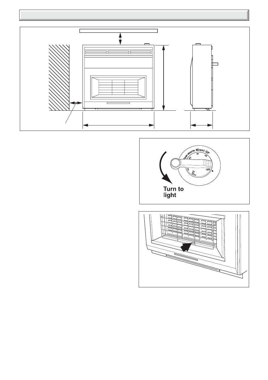
The control is shown in diagram 2.
Depress the control knob and turn anticlockwise towards the 1/
IGN position. A spark should be generated at the pilot while
turning. The spark should ignite the pilot. The pilot flame can be
seen through the opening immediately below the centre radiant
- See diagram 3.
If the pilot does not light, turn the knob back to OFF and try
again.
In the unlikely event of failure of the ignition mechanism the pilot
can be lit with a long match or taper - See next page.
When the pilot has lit keep the knob depressed for about ten
seconds to allow the flame sensing probe to warm up.
Diagram 1
Diagram 2
Diagram 3
The control knob can then be set to your preferred heat level.
The settings are:
Knob
Radiants Condition
Position
2
Centre radiant on low. Outer radiants off.
3
Centre radiant fully on. Outer radiants off.
4
Centre radiant fully on. Outer radiants on low.
5
All radiants fully on.
9421
9402
SEE SAFETY INSTRUCTIONS
12mm MINIMUM
EITHER SIDE
686mm
203mm
625mm
9424
5
221917C
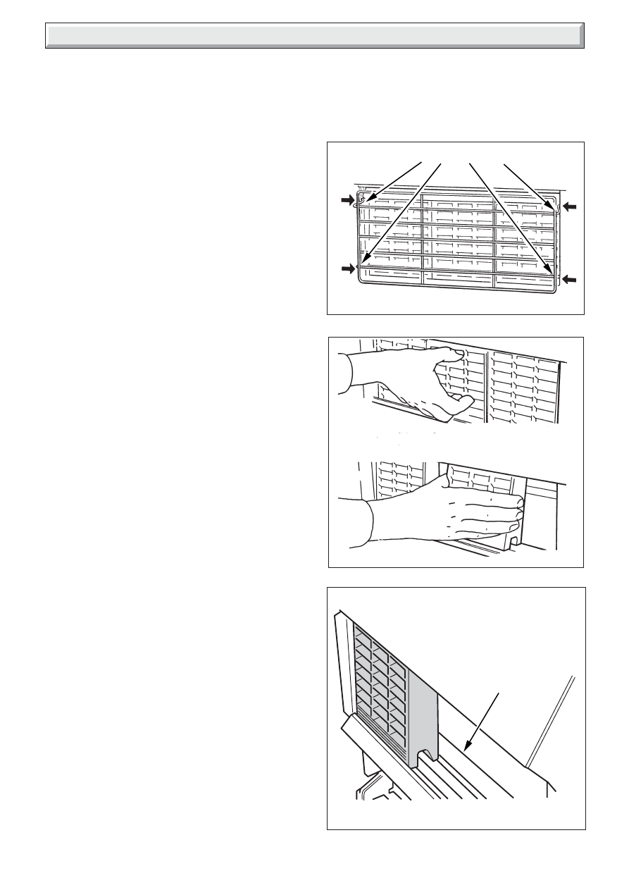
Diagram 4
LOCATION PINS
1678
0723
Diagram 5
Diagram 6
To exchange a radiant first ensure the fire is cold and
remove dressguard.
Lift up the radiant at the bottom and withdraw forward.
Instructions for Use
To Turn the Fire Off
Partially depress the knob and turn clockwise to off.
Wait at least three minutes before attempting to relight.
Lighting with a match or taper
Depress the control knob and turn anticlockwise towards the 1/
IGN position.
While keeping the knob depressed,light the pilot by inserting a
long match or taper into the pilot viewing opening, see diagram
3.
When the pilot is alight, keep the knob depressed for about ten
seconds to allow the flame sensing probe to warm up before
setting to your preferred heat level.
For your own convenience, have the heater serviced as soon as
possible.
CLEANING
Turn the fire off and allow it to cool before attempting any
cleaning.
Normally the fire will only need dusting. The bright metal trims
may be cleaned with a damp cloth and dried with a soft duster.
The wood case can be polished with furniture polish from time
to time.
Obstinate marks can be removed from the guard and trims
using soapy water. Never use abrasive cleaners.
The radiants can be cleaned with a soft brush - see the next
section for how to remove the radiants.
REPLACING RADIANTS
Make sure that the fire is cold
Remove the dress guard by holding the outer edge and flexing
the centre outwards to release the upper and lower locating
pins. See diagram 4.
Lift up the centre radiant from the bottom and withdraw forwards.
Move the other radiants to the centre and remove in a similar
way. See diagram 5.
To replace, insert the top of the radiant first then the bottom.
Lower into position. The back of the radiant should rest against
the rear ribs of the metal fire box and the bottom front edge of
the radiant should be behind the metal retaining bar. See
diagram 6.
It will be found easier to replace the radiants at the centre and
move them left or right.
Replace the dress guard.
We suggest that the position of the radiants is changed from
time to time to equalise any colour change caused during use.
MAINTENANCE
Regular maintenance
In order to achieve and maintain high levels of personal safety
and performance efficiency, it is essential that the opening at
the back of the fire and the flue are kept clear of any form of
obstruction. It is possible that deposits of mortar or soot could
fall and accumulate causing the flue to be blocked or restricted
and so preventing proper clearance of dangerous exhaust
fumes.
In the United Kingdom it is the law that a landlord must have any
gas appliance, flue and pipework which is situated in a tenant’s
premises checked for safety at least every twelve months by a
competent person (In the U.K, a CORGI registered installer).
We recommend that all gas appliances and their flues, wherever
situated, are checked annually.
Servicing
Use only genuine Glow-worm parts. Buy them from a recognised
supplier.
For all service enquiries please quote that the appliance is a
Glow-worm Miami GF, GC No. 32-047-05.
Radiants to touch
rear rib
9426
6
221917C
1 Installation Requirements
Diagram 1.1
This appliance does not contain any component manufactured
from asbestos or asbestos related products.
The appliance data label is on the inner face of the back panel
at the lower left hand side. It is visible when the outer case is
removed.
1.1 Data
Gas
Natural (G20)
Inlet Pressure
20mbar
Gross Heat Input
Max.
5.01kW (17,220Btu/h)
Min.
1.13kW (3,880Btu/h)
Max. Output
3.58kW (12,215Btu/hr)
*
Burner Test
Pressure (Cold)
17.95+0.75mbar (7.2+0.3in w.g.)
Gas Connection
8mm pipe
Burner Injector
Upper
(Centre Radiant)
Bray Cat. 28 Size 120
Lower
(Outer Radiants)
Bray Cat. 28 Size 250B
Pilot & Atmosphere
Sensing Device
OP9093
Ignition
Piezo-electric integral with gas tap
Aeration
Non-adjustable
Total Weight
17.1Kg
*
As tested in accordance with BSI Document No. 98/708846.
1.2 Statutory Requirements
The installation must be in accordance with these instructions.
For the user’s protection, in the United Kingdom it is the law that
all gas appliances are installed by competent persons in
accordance with the current edition of the Gas Safety (Installation
and Use) Regulations. Failure to install the appliance correctly
could lead to prosecution. The Council for the Registration of
Gas Installers (CORGI) requires its members to work to
recognised standards.
In the United Kingdom the installation must also be in accordance
with:
• All the relevant parts of local regulations.
• All relevant codes of practice.
• The relevant parts of the current editions of the following British
Standards:-
BS 715, BS 1251, BS 1289 Part 1, BS EN 1806,
BS 4543 Part 2, BS 5440 Parts 1 and 2, BS 5871 Part 1,
BS 6461 Part 1, BS 6891.
• In England and Wales, the current edition of the Building
Regulations issued by the Department of the Environment and
the Welsh Office.
• In Scotland, the current edition of the Building Standards
(Scotland) Regulations issued by the Scottish Executive.
• In Northern Ireland, the current edition of the Building regulations
(Northern Ireland) issued by the Department of the Environment
for Northern Ireland.
• In the republic of Ireland the installation must also conform to
the relevant parts of:
• The current edition of IS 813
• All relevant national and local rules in force.
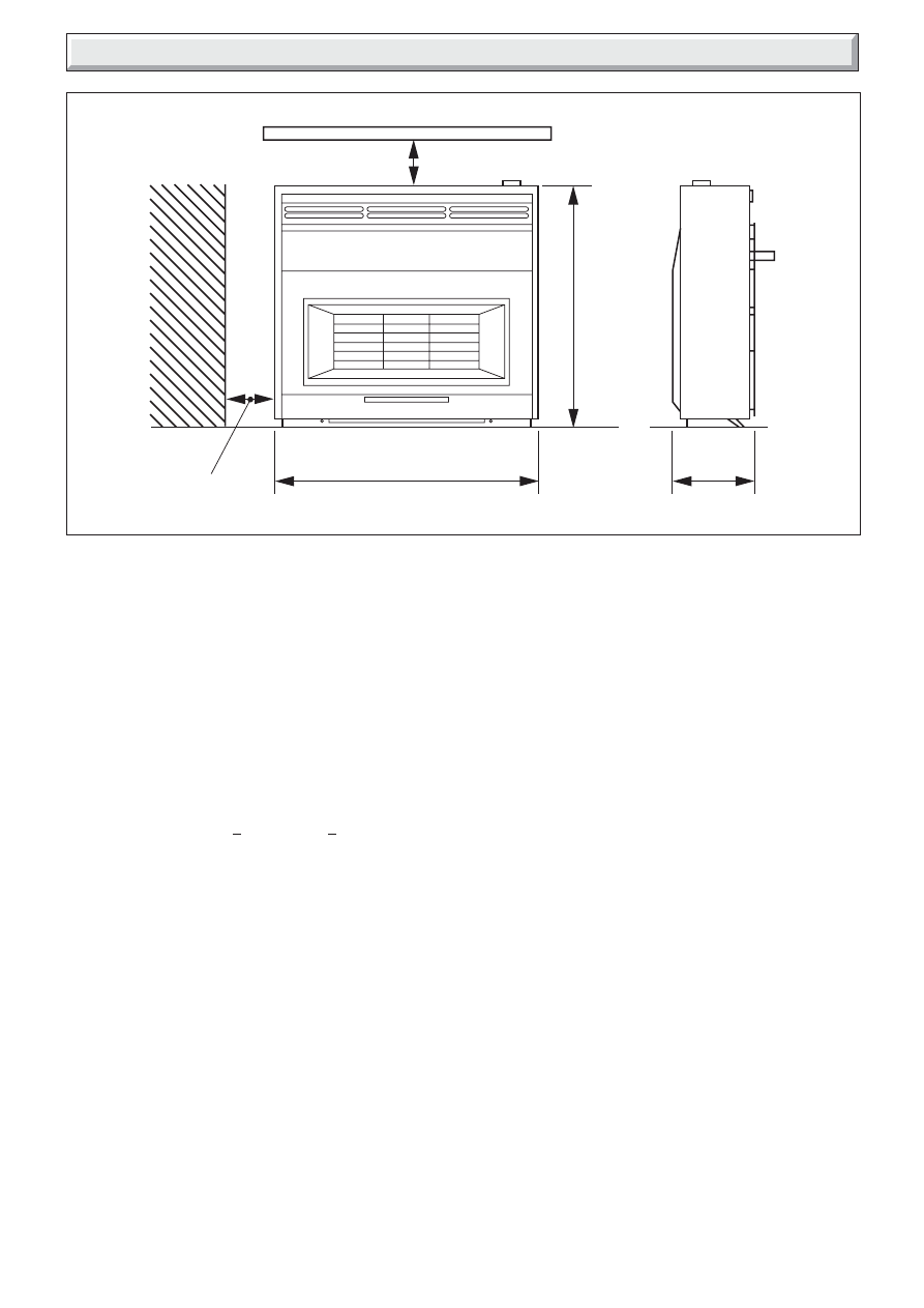
DIMENSIONS & CLEARANCES
SEE SECTION 1.10.
12mm MINIMUM
EITHER SIDE
686mm
203mm
625mm
9424
7
221917C
1 Installation Requirements
Diagram 1.2
Diagram 1.3
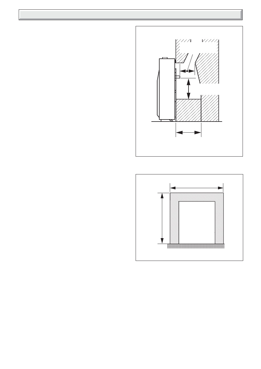
1.3 Fire Location
• If the fireplace opening is an underfloor draught type, it must
be sealed to stop any draughts.
• The flue spigot and any spigot extension must be capable of
passing through the closure plate by at least 25mm with a
minimum clearance of 50mm between its open end and the
nearest obstruction. See diagram 1.2
• There must also be a minimum clearance of 165mm between
the back of the closure plate and the back of the catchment
space. See diagram 1.2.
• The catchment space below the flue spigot must extend at
least 250mm downwards measured from the bottom of the flue
spigot. See diagram 1.2.
• The front of the fireplace should be flat over an area sufficient
to ensure a good seal with the closure plate. The flat surface
should extend for a height equal to that of the closure plate plus
20mm and a for a width equal to that of the closure plate plus
40mm.
• If the fire is to be fitted against walls with combustible cladding,
the cladding must be removed from the area shown in diagram
1.3.
• In the United Kingdom, as supplied, this appliance can be
installed in the following situations:-
1.4 Conventional Fireplace
The fireplace opening must be within the following dimensions:
Width
Max.
440mm
Min.
305mm
Height
Max.
610mm
*
Min.
525mm
*
Though the total height of the closure plate will accommodate
a maximum opening height of 650mm, heights above 610mm
will leave the closure plate and sealing tape visible above the
appliance.
• The appliance must be mounted on a non-combustible hearth
(N.B. conglomerate marble hearths are considered as non-
combustible). The hearth must be at least 880mm wide x
300mm deep. The hearth material must be at least 12mm thick.
The periphery of the hearth (or fender) should be at least 50mm
above floor level to discourage the placing of carpets or rugs
over it.
• The appliance can be fitted to a purpose made proprietary
class “O” 150°C surround.
1.5 Wall Mounted
The wall opening must be within the following dimensions:
Width
Max.
440mm
Min.
305mm
Height
Max.
610mm
*
Min.
350mm
*
Though the total height of the closure plate will accommodate
a maximum opening height of 650mm, heights above 610mm
will leave the closure plate and sealing tape visible above the
appliance.
• The bottom of the appliance must be at least 50mm above the
finished floor covering. See diagram 1.1. This requires the top
of the opening to be at least 575mm above the finished floor
covering. Any opening visible below the appliance may be
closed in but the depth of the catchment space within the wall
opening must be as shown in diagram 1.2.
FIREPLACE CATCHMENT SPACE
AREA TO BE FREE OF
COMBUSTIBLE CLADDING
9427
9425
NOT LESS THAN
165mm
NOT LESS THAN
250mm
NOT LESS THAN
50mm
520mm
615mm

8
221917C
1.6 Precast Flues
• The appliance can be installed to a fireplace that has a properly
constructed precast concrete or clay flue block system
conforming to BS1289 or BS EN 1806. The appliance is suitable
for installations conforming to older versions of BS1289 as well
as the current standards. The flue blocks must have a minimum
width not less than 63mm and a cross-sectional area not less
than 13,000mm
2
.
Older editions of BS1289 required a cross-
sectional area of 13,000mm
2
. The current revision of the standard
requires 16,500mm
2
. This appliance is suitable in both cases.
• The chimney should be one or two storeys high but not less
than 3m vertical height and be correctly terminated. No mortar
fangs between the blocks should be extruded into the flueway.
If raking blocks are used, they must be fitted in accordance with
the manufacturer’s instructions. Mortar must not be allowed to
drop down and accumulate in the raked positions.
• The fireplace opening must be within the following dimensions:
Width
Max.
440mm
Min.
305mm
Height
Max.
610mm
1
Min.
610mm
2
1
Though the total height of the closure plate will accommodate
a maximum opening height of 650mm, heights above 610mm
will leave the closure plate and sealing tape visible above the
appliance.
2
Any opening visible below the appliance may be closed in.
1.7 Metal Flue Box
• The appliance can be installed to a metal flue box conforming
to BS715 Section 6 (For gas fires to BS5258:Part5) having a
minimum internal depth of 165mm.
• The opening must be within the following dimensions:
Width
Max.
440mm
Min.
380mm
Height
Max.
610mm
*
Min.
525mm
*
Though the total height of the closure plate will accommodate
a maximum opening height of 650mm, heights above 610mm
will leave the closure plate and sealing tape visible above the
appliance.
1.8 Flue Requirements
The following flues are suitable:
• 225mm x 225mm conventional brick flue.
If a flue liner is used, it must be a minimum of 125mm diameter.
The liner must be sealed to the surrounding area above the
fireplace opening and to the top of the chimney. An approved
terminal must be fitted.
• A properly constructed precast flue conforming to B.S 1289 or
BS EN 1806.
• A flue pipe with a minimum diameter of 127mm. See B.S 6461
Part 1 for suitable materials. Metal flue pipes must comply with
B.S 715. See section 2.9.4 of this guide for flue box opening
sizes.
• The flue must conform to BS 5440: Part 1 in design and
installation.
• The flue, measured from the bottom of the fireplace opening
to the bottom of the terminal, shall be not less than 3m in actual
vertical height. When calculated in accordance with BS 5440:
Part 1 Annex A, the minimum equivalent height of the flue shall
be 2.0m of 125mm dia. flue pipe.
The flue must be clear of any obstruction and its base must be
clear of debris.
The flue must be completely sealed so that combustion products
do not come into contact with combustible materials outside the
chimney.
The flue must serve only one fireplace.
Proprietary terminals must comply with BS 715 or BS 1289. Any
terminal or termination must be positioned in accordance with
BS 5440 Part 1 to ensure that the products of combustion can
be safely dispersed into the outside atmosphere. Where the
appliance is connected to an unlined brick chimney it is generally
unnecessary for the chimney pot to be replaced or for a terminal
to be fitted unless the flue has a diameter smaller than 170mm.
If the appliance is intended to be installed to a chimney which
was previously used for solid fuel, the flue must be swept clean
prior to installation. All flues should be inspected for soundness
and freedom from blockages.
Any chimney dampers or restrictors should be removed. If
removal is not possible they must be fixed in the open position.
1.9 Ventilation
In the United Kingdom (GB) special ventilation bricks or vents
are not normally required in the room for this appliance.
In the Republic of Ireland (IE), permanent ventilation must
comply with the regulations currently in force.
An extractor fan may only be used in the same room as this
appliance, or in any area from which ventilation for the appliance
is taken, if it does not affect the safe performance of the
appliance. Note the spillage test requirements detailed further
on in this manual. If the fan is likely to affect the appliance, the
appliance must not be installed unless the fan is permanently
disconnected.
1.10 Appliance Clearances
Note that soft wall coverings (e.g. embossed vinyl, etc.) are
easily affected by heat. They may scorch or become discoloured
when close to a heating appliance. Please bear this in mind
when installing.
The minimum allowable distance from the outside of the
appliance case to a corner wall or other combustible surface
which projects beyond the front of the appliance is 12mm at
either side. See diagram 1.1.
Allow a minimum clearance of 110mm from the top surface of
the appliance case to the underside of any shelf whether it is
made from combustible or non-combustible materials. This
clearance is necessary to allow the case to be lifted off for
servicing and also allows the owner sufficient access to operate
the control knob.
A shelf made from wood or other combustible materials
deeper than 150mm must have a minimum clearance of
110mm + 12.5mm for every 25mm depth over 150mm. See
diagram 1.1.
The space between the fireplace front face and the back of the
outer case must not be filled in.
1.10 Room Restrictions
The appliance must not be installed in any room, which contains
a bath, or shower or where steam is regularly present.
1 Installation Requirements
9
221917C
2 Pre-installation Preparation
Diagram 2.1
2.1 Unpacking
This appliance is supplied completely assembled except for:-
• 3 radiants which are in a cardboard pack inside the firebox.
• The closure plate
• Literature pack
• An olive & olive nut for gas line connection
Remove all the items carefully to prevent damage. Some items
may be contained in the packaging fitments -Examine the
packaging carefully before discarding. Check that all the items
are present and undamaged.
2.2 Fireplace Flue Pull
Close all doors and windows in the room in which the appliance
is to be installed. After confirming with a match that smoke is
drawn into the flue, light a 13 gram smoke pellet and check that
there is a definite flow through the flue. Verify outside that the
smoke exits from one terminal only and that the termination is
suitable. Observe, where possible, upstairs rooms and loft
spaces for signs of escaping smoke indicating a defective flue.
If there is not a definite flow warm the flue for a few minutes and
repeat the smoke pellet test. If there is still no definite flow the
flue may need remedial work - Do not fit the appliance until
there is a definite flow through the flue.
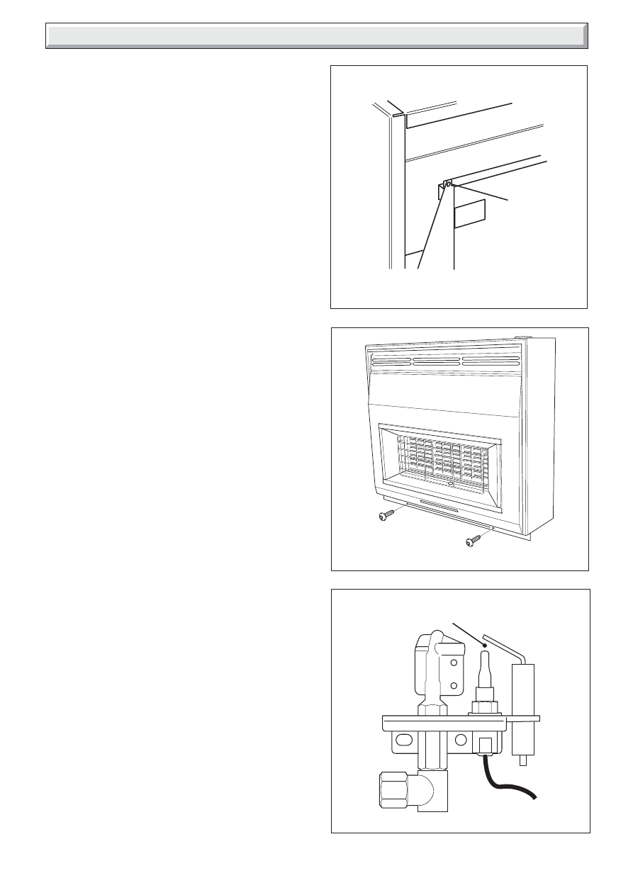
2.3 Appliance Preparation
Stand the fire upright.
Remove the two transit screws from the top of the back panel,
see diagram 2.1
Remove the control knob by pulling clear of the gas tap spindle.
Remove the two case retaining screws located at the front of the
case near the bottom. See diagram 2.2.
Lift the case up and forward to clear the rear top location and
store in a safe place.
Remove the radiant pack.
Remove any protective film from all the bright trims.
2.4 Check ignition spark
Before attempting to install, it is worth checking that the piezo
electric spark ignition system operates satisfactorily.
To initiate the spark, temporarily refit the control knob to the
spindle. Depress the knob and while keeping it depressed, turn
to the 1/IGN position. A spark should track from the electrode pin
to the thermocouple tip. If there is no spark or incorrect tracking,
check the spark gap between the electrode wire and
thermocouple tip. See diagram 2.3.
If the spark gap is correct but there is no spark check the ignition
wiring.
If the fire is fitted to a recessed fireplace, an extension flue spigot
up to a maximum total length of 125mm may be used. The
extension must be a tight fit over the flue spigot and be secured
by two self tapping screws. Note the minimum clearance required
as shown in diagram 1.2.
Diagram 2.2
CASE ATTCHMENT SCREWS
PILOT SPARK GAP
9464
9421
TRUE GAP
3.0mm - 5.0mm
Diagram 2.2
9421
TRANSIT
SCREW
(2off)
10
221917C
3 Closure Plate Installation
Diagram 3.1
Diagram 3.2
Diagram 3.3
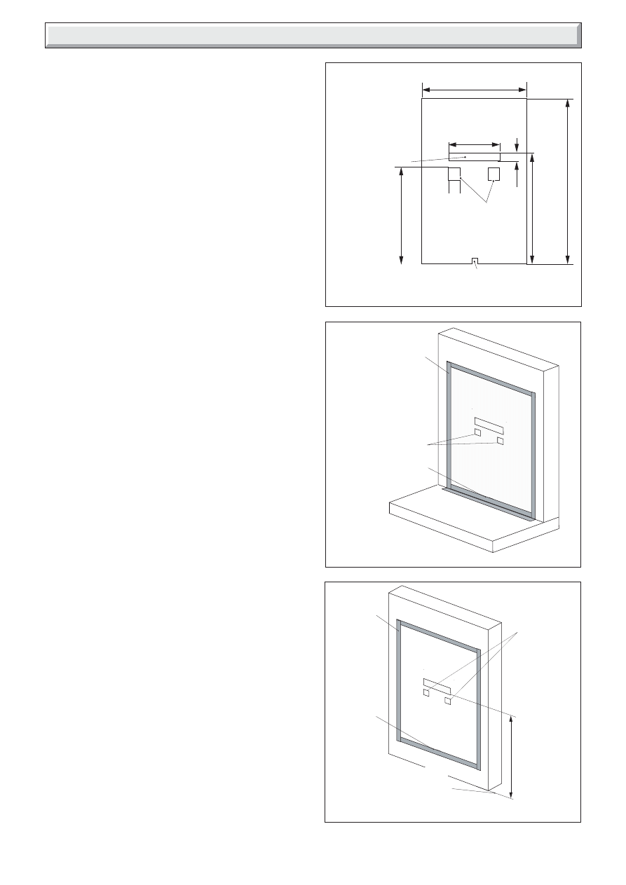
3.1 Closure Plate Details
The closure plate details are shown in diagram 3.1.
The closure plate has an opening at the bottom for a central gas
feed pipe. The gap between the pipe and this opening should be
sealed with tape after connection. If a central feed pipe is not
required the opening should be completely sealed with tape.
3.2 Hearth mounting
See diagram 3.2.
The closure plate must be fitted and sealed to the hearth and
fireplace opening using a suitable heat resistant material. If
necessary cut the closure plate but make sure that it overlaps
the fireplace opening sufficiently to allow satisfactory sealing.
Make sure that the rectangular air relief openings are fully within
the fireplace opening.
3.3 Wall mounting
See diagram 3.3.
The closure plate must be fitted and sealed to the hearth and
fireplace opening using a suitable heat resistant material. If
necessary cut the closure plate but make sure that it overlaps
the fireplace opening sufficiently to allow satisfactory sealing.
Make sure that the rectangular air relief openings are fully within
the fireplace opening.
The bottom of the appliance must be at least 50mm above any
carpet or other floor covering. To achieve this, the bottom of the
flue spigot opening must be at least 495mm above the finished
floor covering.
3.4 Flue Pull Check
Check the flue pull with closure plate fitted by applying a lighted
match or smoke match to the flue spigot opening in the closure
plate and observe the smoke. If there is a definite flow continue
with the installation. If not check the fitting of the closure plate.
The fireplace flue pull check described in section 2.2 should
have confirmed that the fireplace itself is satisfactory.
CLOSURE PLATE
CLOSURE PLATE FOR
HEARTH MOUNTING
CLOSURE PLATE FOR
WALL MOUNTING
10172
10173
10174
225mm
460mm
660mm
425mm
475mm
30mm
FLUE
SPIGOT
OPENING
2 AIR RELIEF
OPENINGS
DO NOT COVER
OR CUT AWAY
OPENING OR CENTRE PIPE.
SEAL OPENING IF NOT USED.
SEAL ALL ROUND
WITH TAPE
KEEP AIR RELIEF
OPENINGS CLEAR
SEAL CENTRAL
FEED PIPE
OPENING
SEAL ALL
ROUND
WITH TAPE
KEEP AIR
RELIEF
OPENINGS
CLEAR
SEAL
CENTRAL
FEED PIPE
OPENING
495mm MIN.
TO BOTTOM
OF FLUE
SPIGOT
OPENING
50mm
TOP OF FINISHED
FLOOR COVERING
11
221917C
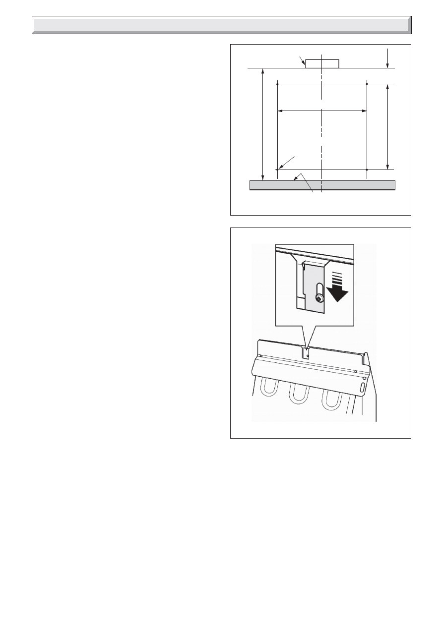
Diagram 4.2
Diagram 4.1
WALL FIXING HOLES
4 Appliance Installation
4.1 Hearth Mounting
Place the fire centrally on the hearth making sure that the spigot
lines up with the spigot hole in the closure plate. Gently slide the
appliance into place. The spigot must enter the closure plate to
a depth of at least 25mm.
Level the fire by loosening the lock nuts and turning the levelling
screws in the feet up or down as required while they bear on the
hearth. When the fire is level and square to the wall, retighten
the lock nuts.
Mark the fixing holes by marking the wall through the holes in the
back panel. Remove the fire, drill and plug the holes using no.
10 wall plugs.
Place the fire in position and secure with four no. 10 x 2in.
woodscrews.
4.2 Wall Mounting
The fixing hole positions in relation to the flue spigot opening are
shown in diagram 4.1. Mark these positions on the wall. The
positions can alternatively be marked by placing the fire in
position and marking the wall through the holes in the back
panel.
Drill and plug the holes using no. 10 wall plugs.
Place the fire in position and secure with four no. 10 x 2in.
woodscrews.
4.3 Gas Supply Connection
8mm rigid tubing must be used to connect the gas supply to the
appliance.
An olive and nut are provided for connection to the “T” connector
on the appliance. The connector can be rotated to allow
connection from either side or the rear. The connector includes
a valve for isolating the gas supply.
The closure plate has a cut-out for rear connection. Seal the gap
between the cut-out and the supply pipe.
Pressure check the installation pipework for gas soundness. In
the United Kingdom check in accordance with the current
edition of BS6891. In the Republic of Ireland check in accordance
with the rules in force.
4.4 Radiants Installation
Fit the radiants ensuring that they rest against the horizontal ribs
in the rear panel and that their bottom front edges are just
behind the retaining channel at the front of the radiant box.
4.5 Flue Restrictor Adjustment
See diagram 4.2.
The appliance has an integral adjustable flue draught restrictor.
This is supplied set in the fully open (unrestricted) position and
in most cases no adjustment should be necessary. It can be
reset to a fully restricted position if the flue draught is excessive.
The restrictor must remain in its fully open position if the
flue has an equivalent height of 4m or less (as calculated in
accordance with BS5440: Part 1 Appendix A) or where a
pre-cast flue is used.
To close the restrictor:
1.
Loosen the screw situated behind the cut-out in the black
upper heat shield. Do not fully remove the screw.
2.
Push the restrictor firmly down as far as it will go.The top
of the slot in the restrictor bracket should touch the screw.
3.
Fully tighten the screw.
There may be certain exceptional circumstances where closing
the restrictor causes the fire to fail the spillage test (See section
7). In such cases the restrictor will have to be reopened.
FLUE RESTRICTOR ADJUSTMENT
FIRE C
L
9410
9411
495mm MIN.
315mm
65mm
SLIDE
DOWN
TO
RESTRICT
FLUE
TOP OF FLOOR COVERING
4 FIXING HOLE
POSITIONS
540mm
FLUE SPIGOT OPENING
12
221917C
5 Control & Pressure Checks
5.1 Check Control Settings
If closed, open the isolating valve at the inlet elbow.
To check the control positions temporarily place the outer case
loosely over the engine. Fit the control knob over the gas tap
spindle.
Depress the control knob and turn anticlockwise partially towards
the 1/IGN position until some resistance is felt.
Keep depressed at this position for a few seconds to purge air
from the system then, while keeping it depressed, turn fully to
the 1/IGN position. A spark should be generated at the pilot
while turning. The spark should ignite the pilot.
When pilot ignition has been achieved, keep the control knob
depressed for approximately ten seconds to allow the
thermocouple probe to warm up and then release it. If the pilot
does not remain alight, ensure that the air has been purged, that
the pilot orifice is clear and that the thermocouple connections
are sound. Replace the pilot unit if necessary (see servicing
section of this manual).
Check all the control settings. These are:-
Knob
Radiants Condition
Position
2
Centre radiant on low. Outer radiants off.
3
Centre radiant fully on. Outer radiants off.
4
Centre radiant fully on. Outer radiants on low.
5
All radiants fully on.
5.2 Flame Supervision & Spillage Monitoring
System
The pilot unit incorporates a system which will automatically
shut off the gas supply if the pilot flame goes out or if there is
insufficient oxygen due to spillage or lack of ventilation.
Check that the system operates properly as follows;
Light the appliance. Set at position 5 and leave for one minute.
Turn back to “OFF” to extinguish the pilot. Note the time when
the pilot goes out.
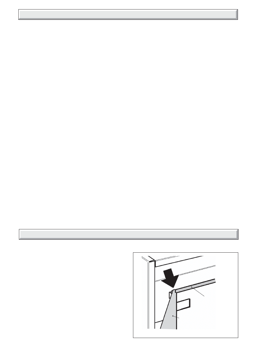
6.1 Outer Case Fitting
Remove the protective wood transit strips (secured with panel
pins) from the bottom of the wooden case sides.
Place the case over the engine. Make sure that the channel
near the top of the rear of the outer case locates fully into the
wings of the engine back panel. See diagram 6.1.
Fit the control knob firmly on to the control spindle.
Refit the two case retaining screws at the front of the case near
the bottom.
Listen for a snap sound at the gas tap. Note the time when the
sound is heard. This sound is caused by an electromagnetic
valve shutting off the gas supply through the tap. The valve is
located in the body of the tap. The valve should operate within
60 seconds of the pilot going out.
If the valve does not operate within this time limit do not allow
the appliance to be used until the fault has been corrected.
This monitoring system must not be adjusted, bypassed or
put out of operation.
This monitoring system, or any of its parts, must only be
exchanged using Glow-worm authorised parts.
5.3 Check Reference Pressure
The appliance is pre-set to give the correct heat input at the inlet
pressure shown in section 1 of this manual. No adjustment is
necessary.
Detach the control knob from the spindle. Remove the outer
case.
Check the burner pressure by fitting a pressure gauge at the test
point. The test point is on the gas tap. Check the pressure with
the appliance alight and set at maximum output (Control position
5).
After checking, turn off the appliance. Remove the pressure
gauge and replace the test point sealing screw. Relight the
appliance. Turn to the maximum output position and test around
the sealing screw for gas soundness with a suitable leak
detection fluid.
If all the above checks are satisfactory, continue with the
installation. If not, check the control and ignition circuitry and
components as described in the servicing section of this manual.
6 Outer Case Fitting
Diagram 6.1
9415
CASE TOP LOCATION
OUTER CASE
CHANNEL
BACK PANEL
WING
13
221917C
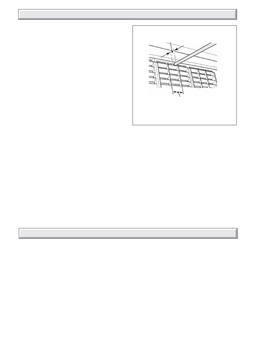
7 Spillage Check
Diagram 7.1
SPILLAGE CHECK
7.1 Spillage Check
A spillage test must be made before the installed appliance
is left with the customer.
Close all doors and windows in the room containing the fire.
Light the appliance and set the control knob to the maximum
position (Position 5).
Leave the appliance on for five minutes.
Place a smoke match tube (with lighted match) horizontally
underneath the radiant box but touching the top lip of the box.
The tube should be between the two vertical inner ribs of the
centre radiant. The tip of the match should project between
2mm and 5mm beyond the lowest edge of the radiant box lip.
See diagram 7.1.
The installation is satisfactory if the smoke is drawn into the
appliance.
If the smoke is not drawn into the appliance, leave the appliance
alight at the maximum setting for a further ten minutes and then
repeat the test.
If the smoke is still not drawn into the appliance, inspect the
sealing of the closure plate.
If the sealing is satisfactory but the appliance is installed with the
flue restrictor in the closed position (see section 4.5), reopen the
restrictor, reseal the appliance and retest.
If smoke is still not drawn into the appliance Disconnect the
appliance and seek expert advice.
If the above test is satisfactory, open all internal connecting
doors, hatches, etc. in the room. Keep all doors and windows
that open to the outside of the building closed. recheck for
spillage as above.
If an extractor fan is installed in the same room as the appliance
or a connecting room, check that spillage does not occur with
the fan operating and all doors and other openings between the
fan and the appliance open.
If the test is satisfactory continue with the installation.
If the test is not satisfactory Disconnect the appliance and
advise the customer of the cause of failure.
8.1 Final Review
Make sure that the radiants and dress guard are securely in
position.
Recheck the operation of the fire at all control positions.
Visually inspect the appliance. Clean off any marks incurred
during installation.
Advise the customer how to operate the fire.
Explain to the customer that the appliance has a flame failure
and spillage monitoring system. Point out the explanation of this
system shown in the Instructions for use. Advise that if the fire
goes out for any reason, wait at least three minutes before
relighting. Stress that if the monitoring system repeatedly shuts
off the fire, the appliance should be switched off and a specialist
should be consulted.
Advise that the dressguard can be removed to replace the
radiants.
Advise that the fire may give off a slight odour while new. This
is quite normal and it will disappear after a short period of use.
Advise that any cleaning must only be carried out when the fire
is off and cold.
Advise the customer that they should read the Instructions for
use before operating the fire.
Advise the user that the appliance can be lit with a match if
necessary by inserting it through the central opening at the
bottom of the radiant box.
Recommend that the appliance should be serviced and the
chimney inspected by a competent person (In the UK a CORGI
registered person) at least annually.
If the appliance is in premises in the United Kingdom occupied
by a tenant, point out that by law a landlord must have any gas
appliance, flue and pipework which is situated in a tenant’s
premises checked for safety at least every 12 months.
Mention that the radiants may become brown with use, that this
is quite normal and has no adverse effect.
Hand these instructions to the customer.
8 Final Review
9416
SMOKE MATCH TO BE
BETWEEN INNER RIBS
OF CENTRE RADIANT
2mm - 5mm INSIDE
RADIANT BOX LIP
14
221917C
Diagram 9.1
9 Servicing & Parts Replacement
REMEMBER, When replacing a part on this appliance, use only
spare parts that you can be assured conform to the safety and
performance specification that we require. Do not use
reconditioned or copy parts that have not been clearly authorised
by Hepworth Heating Ltd.
Always turn off the gas supply before commencing any
servicing (The appliance inlet “T” connector incorporates
an isolating valve).
It is recommended that, at least once a year, the appliance
is disconnected and the catchment space behind the closure
plate checked and cleared of any debris. The closure plate
must be resealed to the wall after checking.
Check that soot or debris is not impairing the electrode spark or
pilot burner.
Check that soot or debris is not blocking any of the holes in the
main burner.
Always test for gas soundness and spillage after servicing
the appliance.
9.1 To Replace Radiant(s)
Remove the dress guard by holding its outer edges and flexing
the centre outwards to release the upper and lower locating
pins.
Remove the old radiant(s) Fit the new radiant(s) ensuring that
they rest against the horizontal ribs in the rear panel and that
their bottom front edges are just behind the retaining channel at
the front of the radiant box.
Replace in the reverse order.
9.2 To Remove the Outer Case
Remove the control knob by pulling clear of the gas tap spindle.
Remove the two case retaining screws located at the front of the
case near the bottom.
Lift the case up and forward to clear the rear top location.
Replace in the reverse order. Make sure that the channel near
the top of the rear of the outer case locates fully into the wings
of the engine back panel. See diagram 6.1 in the installation
section.
Make sure that the radiants are not dislodged when refitting the
case.
9.3 To Replace the Pilot Unit
Remove the outer case as section 9.2 above.
Disconnect the thermocouple connection at the bottom of the
gas tap.
Disconnect the pilot pipe from the gas tap. It is the upper
connection at the right side of the tap.
Remove the first screw securing the dust cage to the pilot unit
& burner bracket. Carefully remove the dust cage and place
aside. Remove the second screw securing the pilot unit to the
burner bracket.
Disconnect the electrode lead from below the pilot electrode.
Carefully remove the pilot unit together with the pilot pipe then
disconnect the pipe from the pilot unit.
Replace in the reverse order.
Note:
1 The pilot unit must be replaced as a whole assembly. Its
individual components are not separately replaceable.
2. Once removed, ensure that the dust cage is cleaned
before refitting. Make sure that it locates squarely onto the
pilot unit without any gaps between the cage edges and
the pilot unit.
9.4 To Remove the Piezo Generator
Remove the outer case as section 9.2.
Disconnect the electrode lead from below the pilot electrode.
Disconnect the control spindle & adapter from the gas tap by
removing the split pin. Lift the adapter clear of the gas tap
spindle.
Remove the circlip holding the piezo generator to the tap.
Replace in the reverse order. Make sure that the control knob
with spindle is correctly turned to agree with the gas tap position
before refitting the split pin.
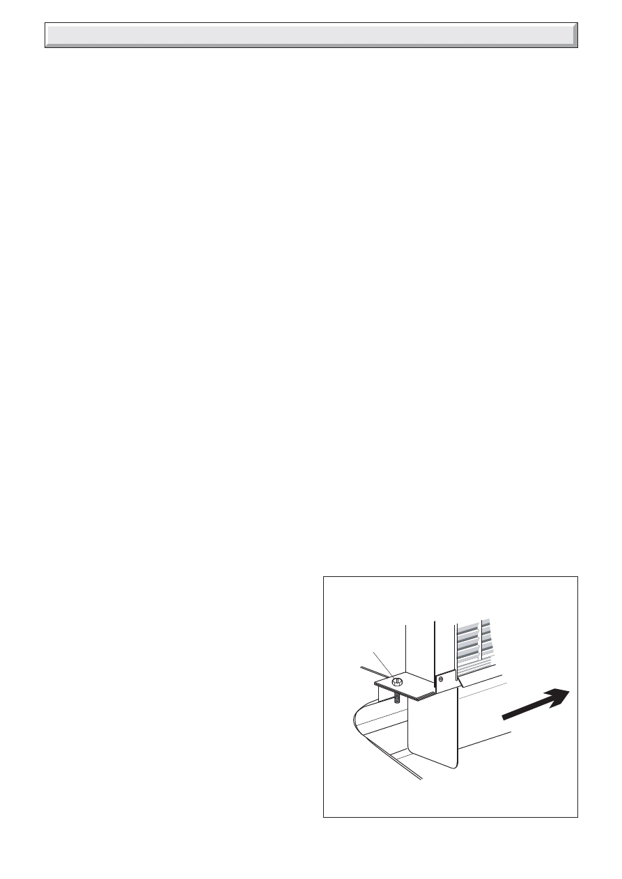
9.5 To Remove The Complete Burner Module,
Pipes and Pilot
Remove the outer case as section 9.2
Support the inlet isolating elbow to avoid straining the pipework
and disconnect the appliance from the elbow.
Disconnect the control spindle & adapter from the gas tap by
removing the split pin. Lift the adapter clear of the gas tap
spindle.
Detach the left end of the burner module from the radiant box by
removing one screw. See diagram 9.1.
Carefully slide the burner module to the right to free it from the
right side of the radiant box. See diagram 9.1.
Remove the pipes, gas tap or injectors as required.
Replace in the reverse order.
Take care when replacing the injectors. The injectors have
ceramic tips at each end. It is important not to allow jointing
compound to get on either end of the injectors.
Make sure that the control knob with spindle is correctly turned
to agree with the gas tap position before refitting the split pin.
BURNER MODULE REMOVAL
9417
1
REMOVE
SCREW
2
SLIDE BURNER UNIT
TO RIGHT
15
221917C
9.6 To Grease the Gas Tap
Remove the burner module as section 9.5.
Remove the circlip holding the piezo generator to the tap.
Remove the two screws from the head of the tap.
Remove the spindle and spring from the tap.
Note the position of the slot in the plug. Mark this position on the
tap body.
Rotate the plug and pull it out of the tap.
Clean and grease the plug lightly with a suitable grease. Do not
apply excessive grease. Particularly, make sure that the gas
ports are not restricted by grease.
Push the plug back into the tap body. Line up the slot in the plug
with the mark previously made on the tap body.
Reassemble in the reverse order making sure that the
components are correctly engaged. Check the operation of the
tap and piezo. Make sure that the control knob with spindle is
correctly turned to agree with the gas tap position before
refitting the split pin.
9 Servicing & Parts Replacement
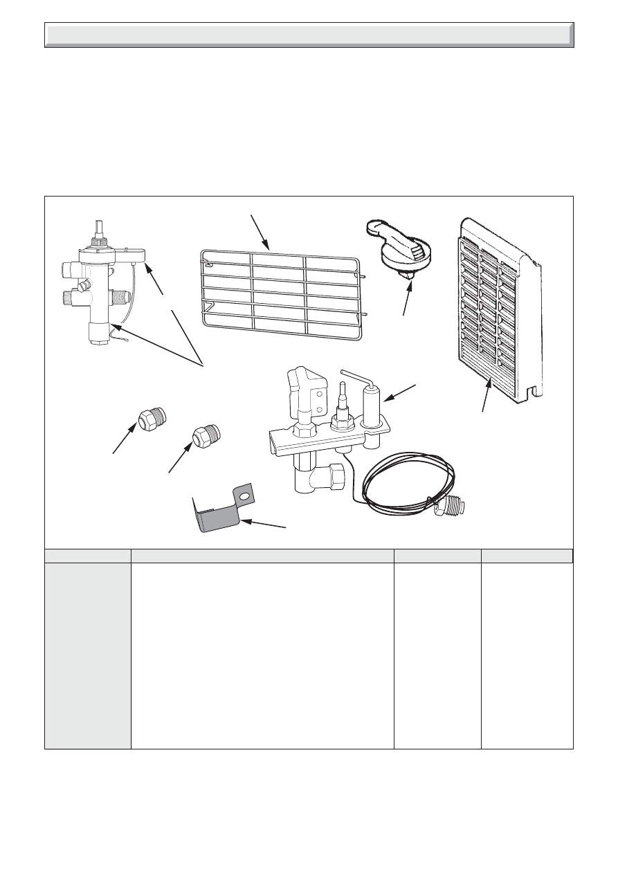
KEY
DESCRIPTION
No. OFF
PART No.
A
Gas Tap & Spark Generator
1
462500
B
Spark Generator
1
462501
C
Upper injector Bray Cat. 28 Size 120
1
462502
D
Lower injector Bray Cat. 28 Size 250B
1
462503
E
Pilot Unit
1
462504
F
Control Knob
1
462506
G
Radiant
3
462507
H
Dress Guard
1
427504
J
Dust cage
1
427509
9423
9466
A
H
F
G
E
C
D
J
B
16
221917C
Because of our constant endeavour for improvement details may vary slightly from those in the instructions.
10 Fault Finding
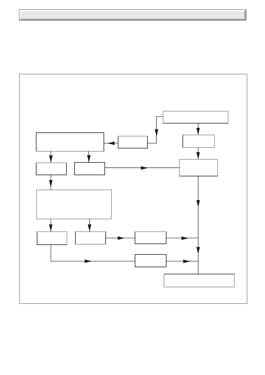
10.1 Ignition Fault Finding
Refer to diagram 10.1.
10.2 Flue Blockage Safety Device
If the device operates it indicates there could be a problem with
the chimney. First make sure air vents are free of obstructions,
by carrying out spillage checks as section 7.1.
Diagram 10.1
IGNITION FAULT FINDING
9467
Disconnect ignition lead from
electrode and place within 4mm of
burner. Operate igniter
No spark
Spark across
gap
Remove ignition lead from piezo unit
and place screwdriver between
applaince chassis and piezo tag,
leaving a 4mm gap between blade
and tag. Operate igniter
No spark
Spark
No spark
Renew ignition
lead
Renew piezo
unit
Reassemble ignition system and
check ignition is satisfactory
Renew Flue
Blockage
Safety Device
Spark
no ignition
Turn on tap to operate igniter and
observe spark
If burner will not light, check the electrode lead connections are satisfactory
and that the burner ports are clean.
Check the electrode gap is correct.
If ignition is still unsatisfactory carry out the following procedure.
Wyszukiwarka
Podobne podstrony:
Glow Worm installation and service manual Miami GF UIS
Glow Worm installation and service manual Hideaway 70CF UIS
Glow Worm installation and service manual Ultimate 50CF UIS
Glow Worm installation and service manual Ultimate 60CF UIS
Glow Worm installation and service manual Hideaway 80BF UIS
Glow Worm installation and service manual Hideaway 120BF UIS
Glow Worm installation and service manual Hideaway 120CF UIS
Glow Worm installation and service manual Ultimate 40CF UIS
Glow Worm installation and service manual Hideaway 100CF UIS
Glow Worm installation and service manual Hideaway 70BF UIS
Glow Worm installation and service manual Hideaway 80CF UIS
Glow Worm installation and service manual Ultimate 40BF UIS
Glow Worm installation and service manual Hideaway 40BF UIS
Glow Worm installation and service manual Hideaway 50BF UIS
Glow Worm installation and service manual Hideaway 60CF UIS
Glow Worm installation and service manual Hideaway 70CF UIS
więcej podobnych podstron