C102988-0 Page 1 of 8
15.05.2008
© The information contained in this document is the sole property of Steerprop Ltd. any reproduction or disclosure in part or whole without written permission is prohibited.
DOC-1017-1
Service Programme
SP20D AND SP20F
Service Manual
Revision history:
REV. DATE MODIFIER DESCRIPTION
0 2.4.2008
AaNi Created
A
B
C
D
E
F

C102988-0 Page 2 of 8
15.05.2008
© The information contained in this document is the sole property of Steerprop Ltd. any reproduction or disclosure in part or whole without written permission is prohibited.
DOC-1017-1
1
SERVICE PROGRAM........................................................................................................................... 3
1.1
A
MONTH AFTER COMMISSIONING
................................................................................................... 3
1.2
D
AILY SERVICE
................................................................................................................................. 3
1.3
W
EEKLY SERVICE
............................................................................................................................. 3
1.4
R
OUTINE SERVICE
12
WEEKS
............................................................................................................ 4
1.5
R
OUTINE SERVICE
36
WEEKS
............................................................................................................ 4
1.6
R
OUTINE SERVICE
52
WEEKS
............................................................................................................ 4
1.7
R
OUTINE SERVICE
3
YEARS
.............................................................................................................. 5
1.8
O
VERHAUL SERVICE
......................................................................................................................... 5
2
SETTINGS AND ADJUSTMENT ........................................................................................................ 6
2.1
L
OCAL CONTROL SELECTION
........................................................................................................... 6
2.2
C
ALIBRATION TEMPERATURE
.......................................................................................................... 6
2.3
C
ONTROL AND INDICATION SYSTEM
Z
ERO ANGLE SETTING
............................................................ 6
2.4
S
ETTING AND ADJUSTMENT TABLE SOFTWARE
................................................................................ 7
2.5
S
ETTING AND ADJUSTMENT TABLE
E
LECTRIC
................................................................................. 7
2.6
S
ETTING AND ADJUSTMENT TABLE
H
YDRAULIC
.............................................................................. 7
2.7
S
ETTING AND ADJUSTMENT TABLE PNEUMATIC
.............................................................................. 7
3
OIL FILLING AND LUBRICATION .................................................................................................. 8
3.1
O
IL VOLUMES
................................................................................................................................... 8
3.2
L
UBRICATION OIL FILTER
................................................................................................................. 8
3.3
A
IR BREATHER
................................................................................................................................. 8
4
CORROSION CONTROL..................................................................................................................... 8
C102988-0 Page 3 of 8
15.05.2008
© The information contained in this document is the sole property of Steerprop Ltd. any reproduction or disclosure in part or whole without written permission is prohibited.
DOC-1017-1
1 S
ERVICE PROGRAM
If there is some failures or malfunctions, should the reason find out immediately and
repair it.
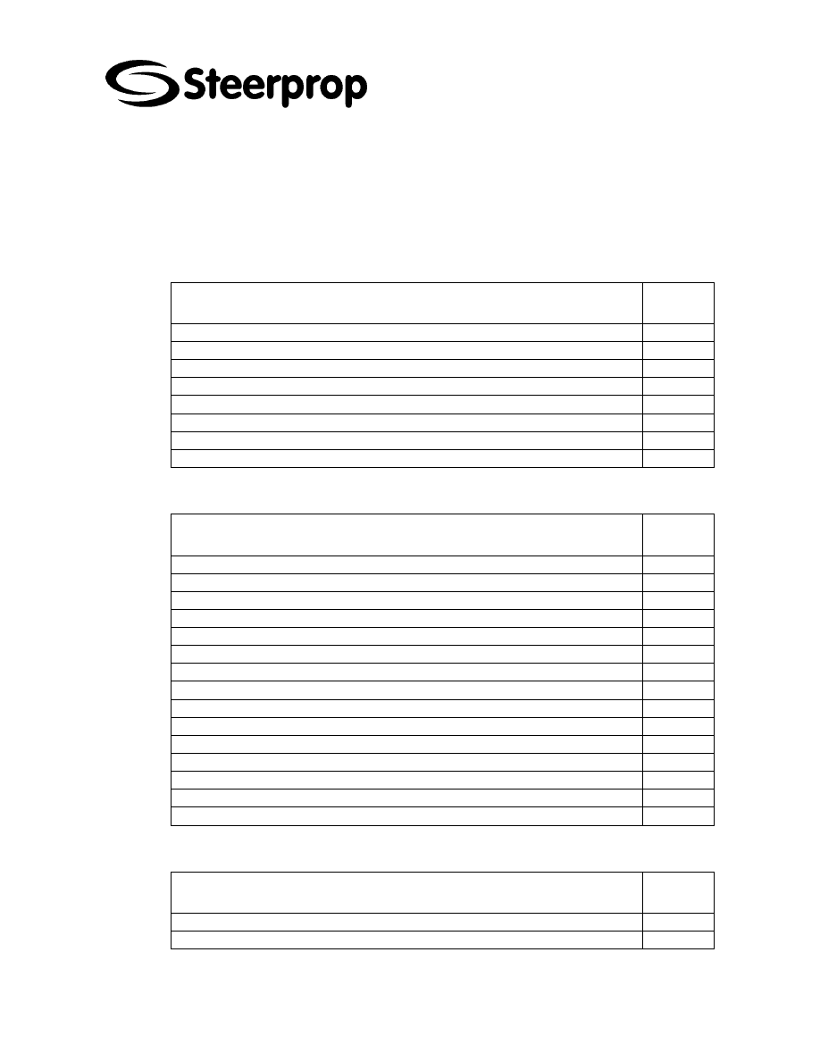
1.1 A
MONTH AFTER COMMISSIONING
SERVICE OPERATION
Check the oil levels
Steering gear magnetic plugs
Air breathers
Oil filters
Electrical connections
Hydraulic connections, oil leakage
Fastenings
Cooling system
1.2 D
AILY SERVICE
SERVICE OPERATION
DAILY
Before starting, check that there is enough oil in propulsor and steering tank
Sealing oil tank oil level
Check lubrication oil temperature
Check steering oil temperature
Cooling system check
Oil and water leakage check
No abnormal noise
Oil filters (warm oil)
Check that suction valves are open (if any).
Test the indication lamps with test push button
Test the operation of back-up controls
Test the operation of main controls
Test the operation of indicators
Test the operation of alarm indicators
1.3 W
EEKLY SERVICE
SERVICE OPERATION
WEEKLY
Check the oil levels at propeller seal oil system
C102988-0 Page 4 of 8
15.05.2008
© The information contained in this document is the sole property of Steerprop Ltd. any reproduction or disclosure in part or whole without written permission is prohibited.
DOC-1017-1
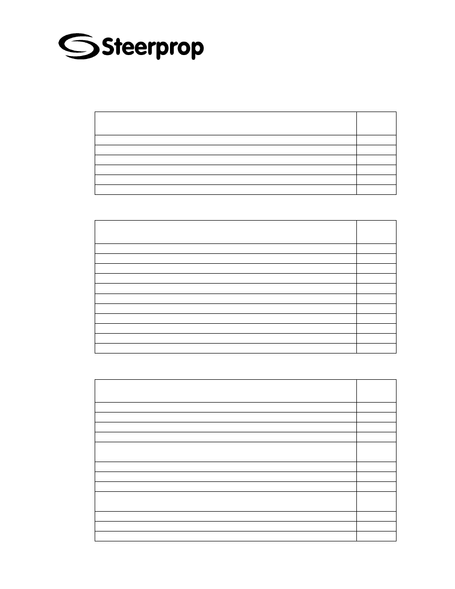
1.4 R
OUTINE SERVICE
12
WEEKS
SERVICE OPERATION
12 WEEKS
Check the installation of couplings of the pump unit
Check the condition of oil visually.
Check the grounding of the electric components
Check the operation of local control
Bulkhead seal nut tightness
1.5 R
OUTINE SERVICE
36
WEEKS
SERVICE OPERATION
36 WEEKS
Lubrication oil condition check
Sealing oil condition check and refreshing if needed
Check the air filter.
Cardan shaft re-greasing
Slip ring unit at intermediate part
Seal oil pressure adjusting valve
Steering motor brake
Intermediate shaft bearings (see hours)
Seal oil air pressure input filter
1.6 R
OUTINE SERVICE
52
WEEKS
SERVICE OPERATION
52 WEEKS
Air gap adjusting at the disc brake at steering motor
Change the filter elements.
The lubrication check of the gears of the steering feedback transmitter
Check the fastening of electrical motor.
Check the bearings of the electrical motors or the belt drive according to free
moving of the shaft and bearing temperature.
Check the fastening of transmitters and indications on the propulsor
Check the fastening of transmitters at the steering motor
Check of the gears and the fastening of the angle feedback transmitters
Check the operation of electric plug connectors, cabling and wiring terminals and
connections
C102988-0 Page 5 of 8
15.05.2008
© The information contained in this document is the sole property of Steerprop Ltd. any reproduction or disclosure in part or whole without written permission is prohibited.
DOC-1017-1
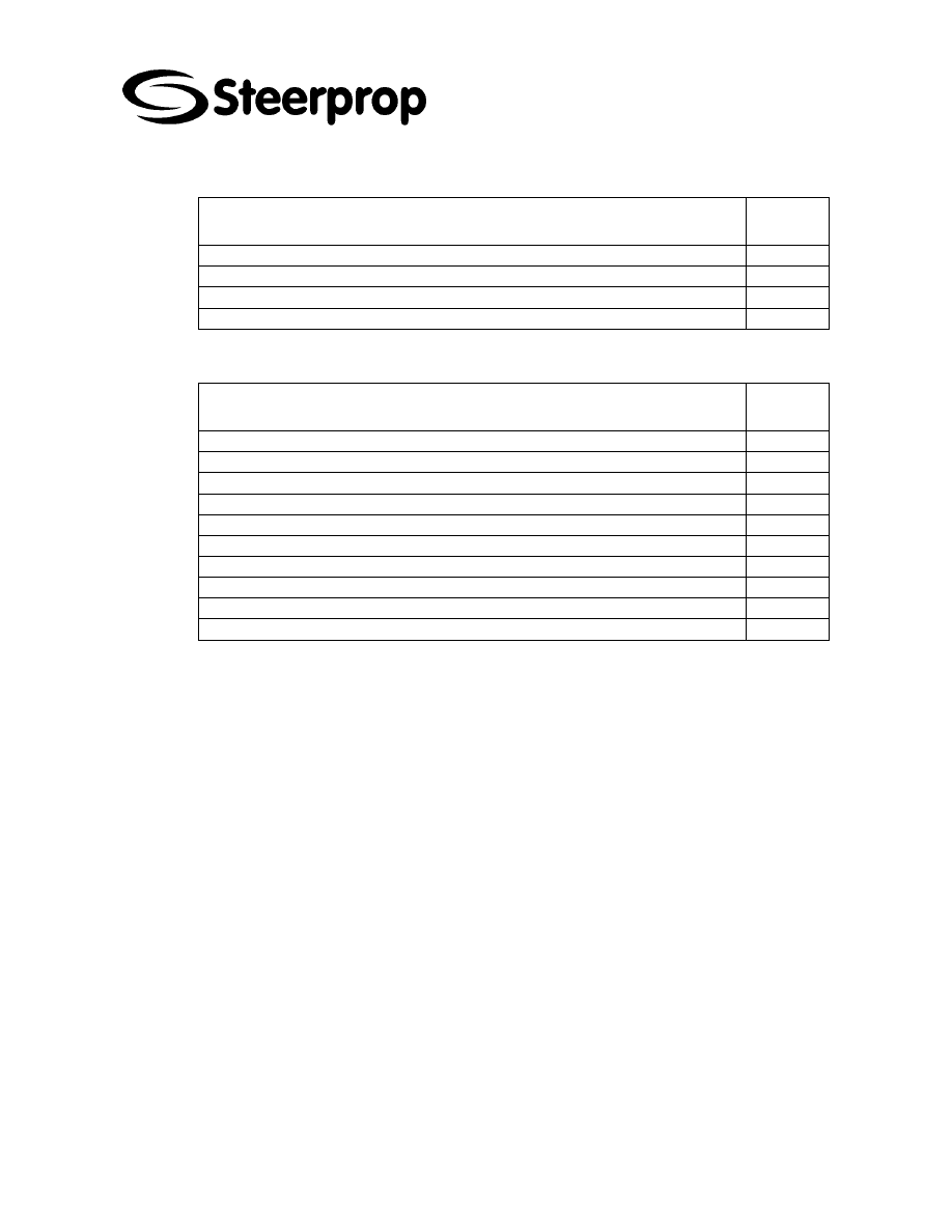
1.7 R
OUTINE SERVICE
3
YEARS
SERVICE OPERATION
3
YEAR
Replace the battery of the A1 unit (PLC)
Replace the battery of ECR displays
The bearing change of electric motors if needed.
1.8 O
VERHAUL SERVICE
SERVICE OPERATION
DRY
DOCK
Replace the battery of the A1 unit (PLC)
Replace the battery of ECR displays
The bearing change of electric motors if needed.
Replace sacrifial anodes at propulsor when needed / dry dock
Replace sacrifial anodes at propeller seal box when needed /dry dock
Propeller shaft seal service when needed / dry dock
Check steering tube seals wearing

C102988-0 Page 6 of 8
15.05.2008
© The information contained in this document is the sole property of Steerprop Ltd. any reproduction or disclosure in part or whole without written permission is prohibited.
DOC-1017-1
2 S
ETTINGS AND ADJUSTMENT
2.1 L
OCAL CONTROL SELECTION
When you do settings or adjustment, you should select local control at SCU to prevent
somebody control the system remotely.
Also is advisable to open the control voltage supply.
2.2 C
ALIBRATION TEMPERATURE
Calibration oil temperature is 20
°C.
2.3 C
ONTROL AND INDICATION SYSTEM
Z
ERO ANGLE SETTING
The following control system steering angle zero settings are going at same time
Steering feedback transmitter RG10
Indication feedback transmitter RG11
*
YOU HAVE TO CHECK THE CALIBRATION OF THE REMOTE ANGLE INDICATORS
AFTER CONTROL SYSTEM ZERO SETTING
C102988-0 Page 7 of 8
15.05.2008
© The information contained in this document is the sole property of Steerprop Ltd. any reproduction or disclosure in part or whole without written permission is prohibited.
DOC-1017-1
2.4 S
ETTING AND ADJUSTMENT TABLE SOFTWARE
FUNCTION
ID
VALUE UNIT SIGNAL UNIT ADJUSTING
PM starting prevention limit
RPM
A1
Lubrication oil pressure alarm
BP02 2
BAR 12
MA A1
Lubrication oil temperature
BT02 75
C
16
MA A1
Steering speed set main control
24
s
ESU
Steering speed set back-up control
50
s
ESU
2.5 S
ETTING AND ADJUSTMENT TABLE
E
LECTRIC
FUNCTION
ID
VALUE UNIT SIGNAL UNIT ADJUSTING
Seal oil pressure low alarm
SP08 0.1
bar
SOT
Steering motor fan circuit breaker
FF1
Steering motor fan circuit breaker
FF2
Steering motor brake circuit breaker
FB1
Steering motor brake circuit breaker
FB2
Lubrication pump motor circuit breaker
FP1
2.6 S
ETTING AND ADJUSTMENT TABLE
H
YDRAULIC
FUNCTION
ID
VALUE UNIT SIGNAL UNIT ADJUSTING
Lubrication oil pressure
PV11 3
bar
Lubrication oil pump overpressure
PV12 8
bar
2.7 S
ETTING AND ADJUSTMENT TABLE PNEUMATIC
FUNCTION
ID
VALUE UNIT SIGNAL UNIT ADJUSTING
Seal oil pressure adjusting
PV
SOT

C102988-0 Page 8 of 8
15.05.2008
© The information contained in this document is the sole property of Steerprop Ltd. any reproduction or disclosure in part or whole without written permission is prohibited.
DOC-1017-1
3 O
IL FILLING AND LUBRICATION
The propulsion unit uses well-known manufacturers mineral oils. The oils are EP-
additive based transmission oils meant for gear units under heavy load. The oil needs
to have good pressure durability and FZG – number > 12.
Recommended oils are in differerent document:
3.1 O
IL VOLUMES
Lubrication oil volume (steerable) .................................................. 1090 litres
Lubrication oil volume (not steerable) .............................................. 960 litres
Seal oil tank........................................................................................ 20 litres
3.2 L
UBRICATION OIL FILTER
Type ................................................................................................................
3.3 A
IR BREATHER
Above the upper gear is with breather equipped oil pipe. If the filter is dirty, it should
clean or change.
4 C
ORROSION CONTROL
The propulsor is equipped with sacrificial anodes/cathodes at following places
It is not allowed to paint those cathodes.
There are cathodes:
Propulsor body
Nozzle
Bottom well
Propeller shaft seal (there is available a replacement kit)
Inside rope guard
Wyszukiwarka
Podobne podstrony:
C102982 0 SERVICE LUBRICATION SP20 STE
3485A SERVICE PROGRAMME
OReilly Programming Web Services with SOAP, OReilly Programming Web Services with SOAP
Prezentacja firmy MARSTATE SERVICE BHP PPOZ PPT
Nowy Prezentacja programu Microsoft PowerPoint 5
Charakterystyka programu
1 treści programoweid 8801 ppt
Programowanie rehabilitacji 2
Rola rynku i instytucji finansowych INowy Prezentacja programu Microsoft PowerPoint
Nowy Prezentacja programu Microsoft PowerPoint ppt
Szkoła i jej program
wykluczenie społ program przeciwdział
więcej podobnych podstron