
Cat. 41-42E
2
MONO RAIL:
NEW ROLLON BALL RECIRCULATING LINEAR GUIDES....................3
MRS SERIES (standard slider)......................................................................4
MRT SERIES (low profile slider)...................................................................5
TECHNICAL DATA:
MRS SERIES (with flange)..............................................................................6
MRS SERIES (without flange)........................................................................7
MRT SERIES (with flange)..............................................................................8
MRT SERIES (without flange)........................................................................9
LOAD CAPACITY, PRELOAD / RADIAL CLEARANCE.........................10
LINEAR PRECISION........................................................................................11
LIFETIME.............................................................................................................12
VERIFICATION UNDER STATIC LOAD......................................................13
MOUNTING METHODS...................................................................................14
MOUNTING PRECISION.................................................................................14
MOUNTING PROCEDURE.............................................................................15
FIXING EXAMPLES..........................................................................................16
ORDER CODES.................................................................................................17
INDEX

Cat. 41-42E
3
MONO RAIL: NEW ROLLON BALL
RECIRCULATING LINEAR GUIDES
ROLLON introduces its new 4-rows circular contact ball recirculating linear guides in the
MONO RAIL family.
This new family is added to the well-known COMPACT RAIL, TELESCOPIC RAIL, EASY RAIL,
UNILINE, ECOLINE, CURVILINE, LIGHT RAIL families, widening again the product range in order
to offer 360° solutions to industrial linear motion problems. As usual in ROLLON, this new family
maintains the large reliability characteristics that have always been the Company ‘trade-mark’.
ROLLON offers MONO RAIL linear guides in seven different sizes, from section 15 mm as far as
section 55 mm.
Sliders are available in two different series, depending from main section profile (standard version
and low profile version), subdivided in two variants following the slider shape (with and without
flanges).
Slider configurations differ in:
- Fixing holes (threaded or cylindrical holes)
- Slider length (normal, long, short).
- Linear precision (normal, high, precision, super-precision, ultra-precision)
- Preload (clearance, no-preload, light-preload, middle-preload, heavy-preload)
Rails and sliders are hardened and ground, moreover every slider mounts a self-lubricating
device that, raising lubrication intervals, reduces maintenance costs.
total protection
high load capacities
high precision
CONTACT ANGLES
90°
45°
45°
high smoothness
self-lubricating
high stiffness
Cat. 41-42E
4
4
6
3
2
5
7
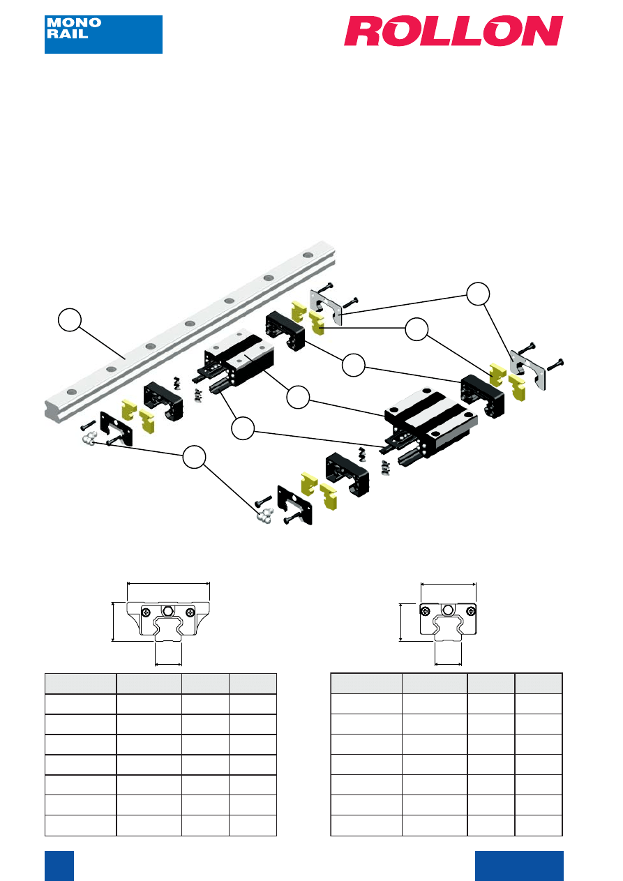
MRS SERIES (standard slider)
It’s a 4-rows circular contact ball recirculating slider with a self-lubricating system coupled with a
rail, all hardened and ground. It’s available in two variants (with or without flanges).
For all technical information (sizes, load capacities, etc.) see page 6 and page 10.
Order codes on page 17.
Available sizes:
MRS..
MRS..W
e
p
y
T
A
)
m
m
(
B
)
m
m
(
C
)
m
m
(
W
5
1
S
R
M
4
3
8
2
5
1
W
0
2
S
R
M
4
4
0
3
0
2
W
5
2
S
R
M
8
4
0
4
3
2
W
0
3
S
R
M
0
6
5
4
8
2
W
5
3
S
R
M
0
7
5
5
4
3
W
5
4
S
R
M
6
8
0
7
5
4
W
5
5
S
R
M
0
0
1
0
8
3
5
e
p
y
T
A
)
m
m
(
B
)
m
m
(
C
)
m
m
(
5
1
S
R
M
7
4
4
2
5
1
0
2
S
R
M
3
6
0
3
0
2
5
2
S
R
M
0
7
6
3
3
2
0
3
S
R
M
0
9
2
4
8
2
5
3
S
R
M
0
0
1
8
4
4
3
5
4
S
R
M
0
2
1
0
6
5
4
5
5
S
R
M
0
4
1
0
7
3
5
A
B
C
List of components:
1. Rail
2. Grease nipple
3. Slider body
4. Head
5. Self-lubricant elements
6. Head cap
7. Low seal (on request)
A
B
C
1
Cat. 41-42E
5
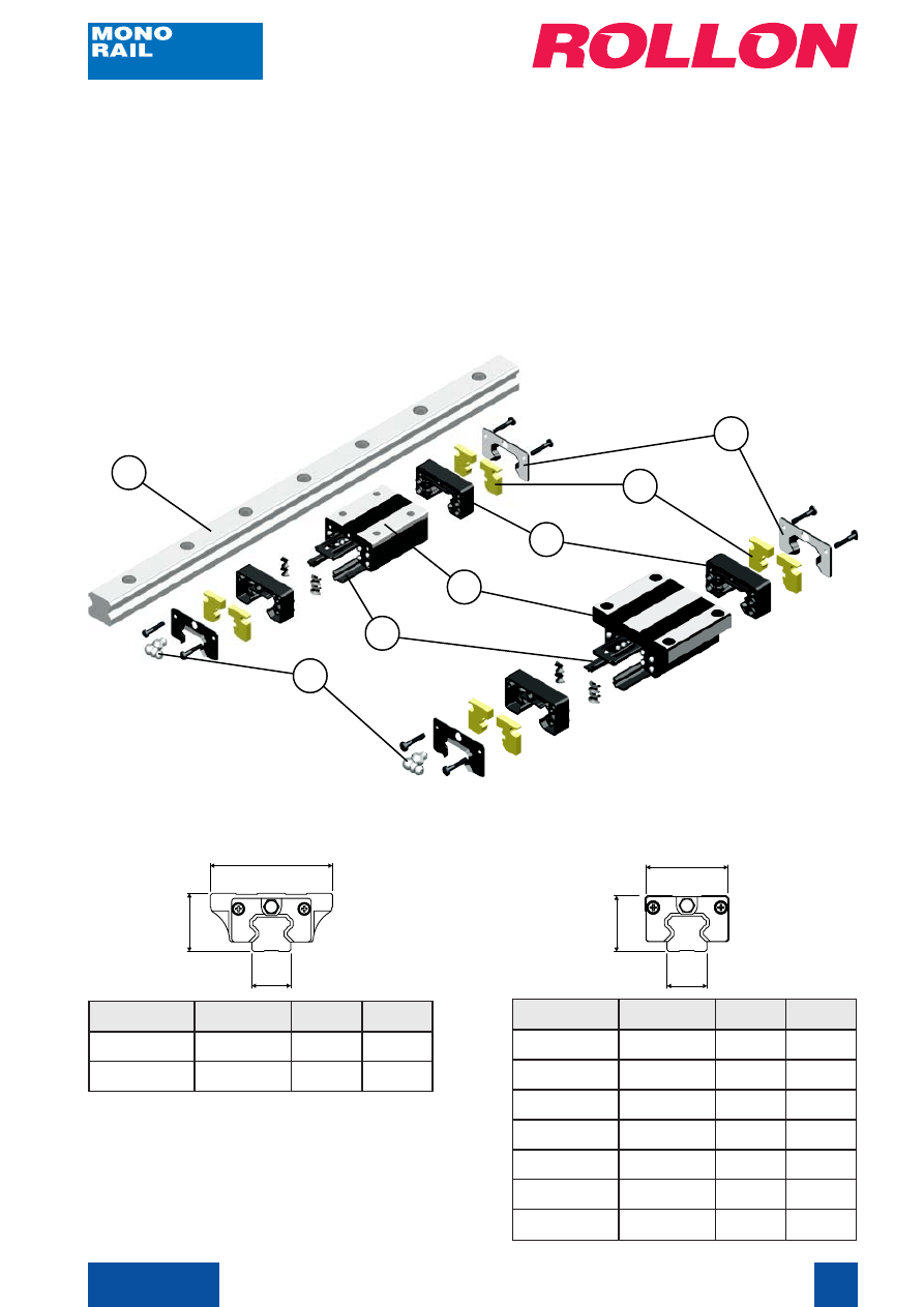
MRT SERIES (low profile slider)
It’s a 4-rows circular contact ball recirculating slider with a self-lubricating system coupled with a
rail, all hardened and ground. It’s available in two variants (with or without flanges).
It’s from MRS series for height overall dimensions (mounted rail/slider).
For all technical information (sizes, load capacities, etc.) see page 8 and page 10.
Order codes on page 17.
Available sizes:
MRT..
MRT..W
e
p
y
T
A
)
m
m
(
B
)
m
m
(
C
)
m
m
(
W
5
1
T
R
M
4
3
4
2
5
1
W
0
2
T
R
M
2
4
8
2
0
2
W
5
2
T
R
M
8
4
3
3
3
2
W
0
3
T
R
M
0
6
2
4
8
2
W
5
3
T
R
M
0
7
8
4
4
3
W
5
4
T
R
M
6
8
0
6
5
4
W
5
5
T
R
M
0
0
1
8
6
3
5
e
p
y
T
A
)
m
m
(
B
)
m
m
(
C
)
m
m
(
0
2
T
R
M
9
5
8
2
0
2
5
2
T
R
M
3
7
3
3
3
2
A
B
C
A
B
C
4
6
3
2
5
7
List of components:
1. Rail
2. Grease nipple
3. Slider body
4. Head
5. Self-lubricant elements
6. Head cap
7. Low seal (on request)
1
Cat. 41-42E
6
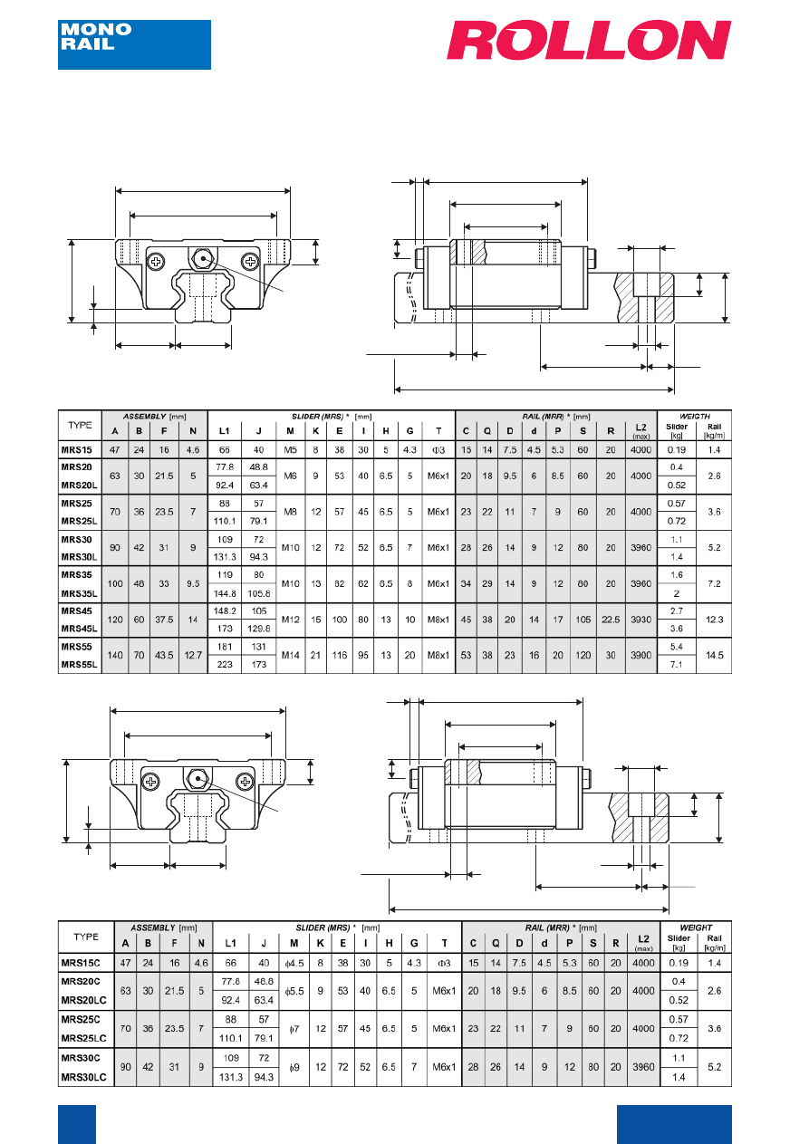
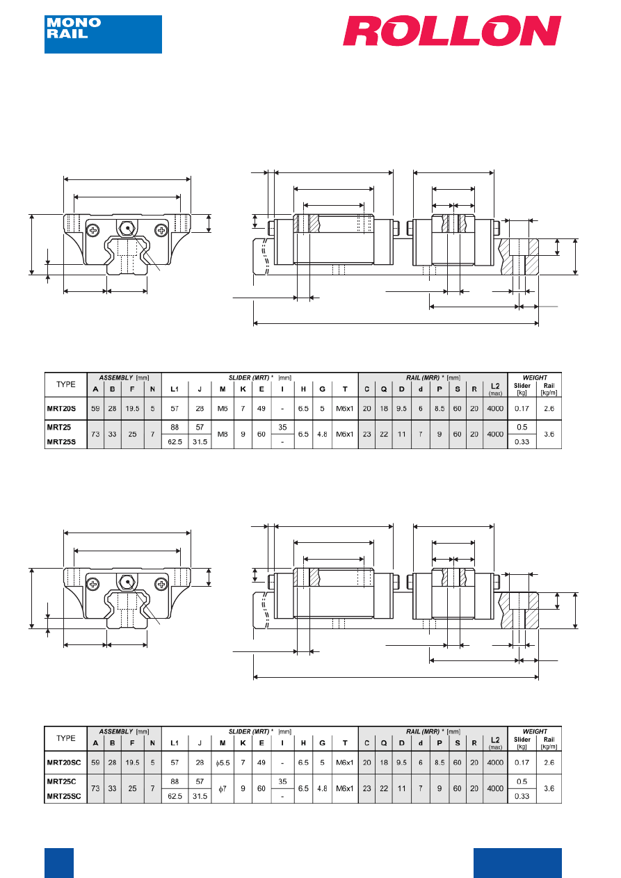
TECHNICAL DATA
MRS Series (with flange)
Threaded holes version
A
B
C
N
E
F
G
M
(n°4 holes)
H
I
J
K
L1
φφφφφ
D
φφφφφ
d
S
(holes pitch)
R
P
Q
L2
max
Cylindrical holes version
A
B
C
N
E
F
G
M
(n°4 holes)
H
I
J
K
L1
φφφφφ
D
φφφφφ
d
S
(holes pitch)
R
P
Q
L2
max
T
(grease nipple)
T
(grease nipple)
* For order codes see page 17
* For order codes see page 17
Cat. 41-42E
7
TECHNICAL DATA
MRS Series (without flange)
A
B
C
N
E
F
G
M
(n°4 holes)
H
I
J
K
L1
* For order codes see page 17
φφφφφ
D
φφφφφ
d
S
(holes pitch)
R
P
Q
L2
max
T
(grease nipple)
Threaded holes version
Cat. 41-42E
8
Threaded holes version
A
B
C
N
E
F
G
M
(n°4 holes)
H
I
J
K
L1
φφφφφ
D
φφφφφ
d
S
(holes pitch)
R
P
Q
L2
max
Cylindrical holes version
T
(grease nipple)
J
L1
M
(n°2 holes)
=
=
A
B
C
N
E
F
G
M
(n°4 holes)
H
I
J
K
L1
φφφφφ
D
φφφφφ
d
S
(holes pitch)
R
P
Q
L2
max
T
(grease nipple)
J
L1
M
(n°2 holes)
=
=
* For order codes see page 17
* For order codes see page 17
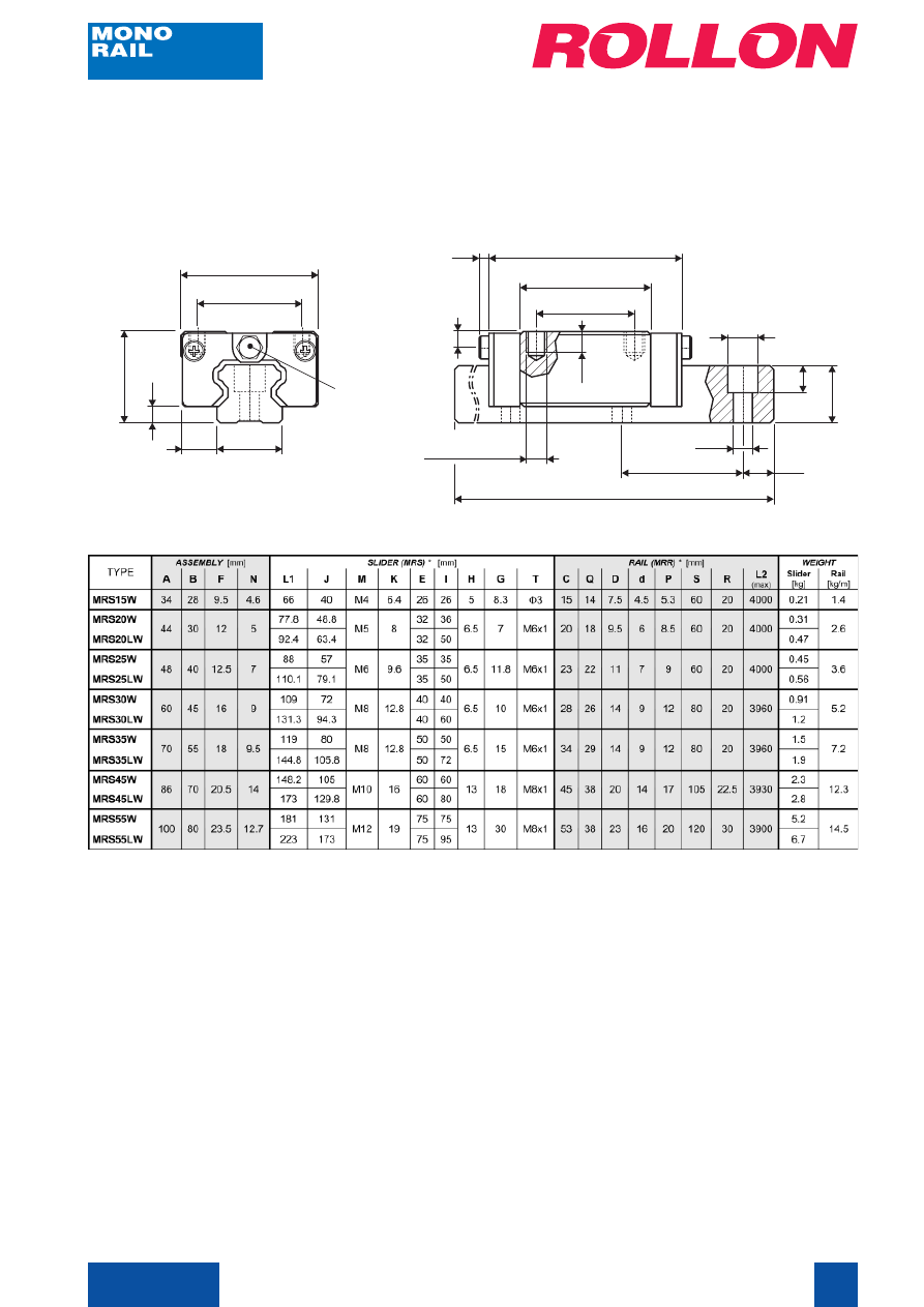
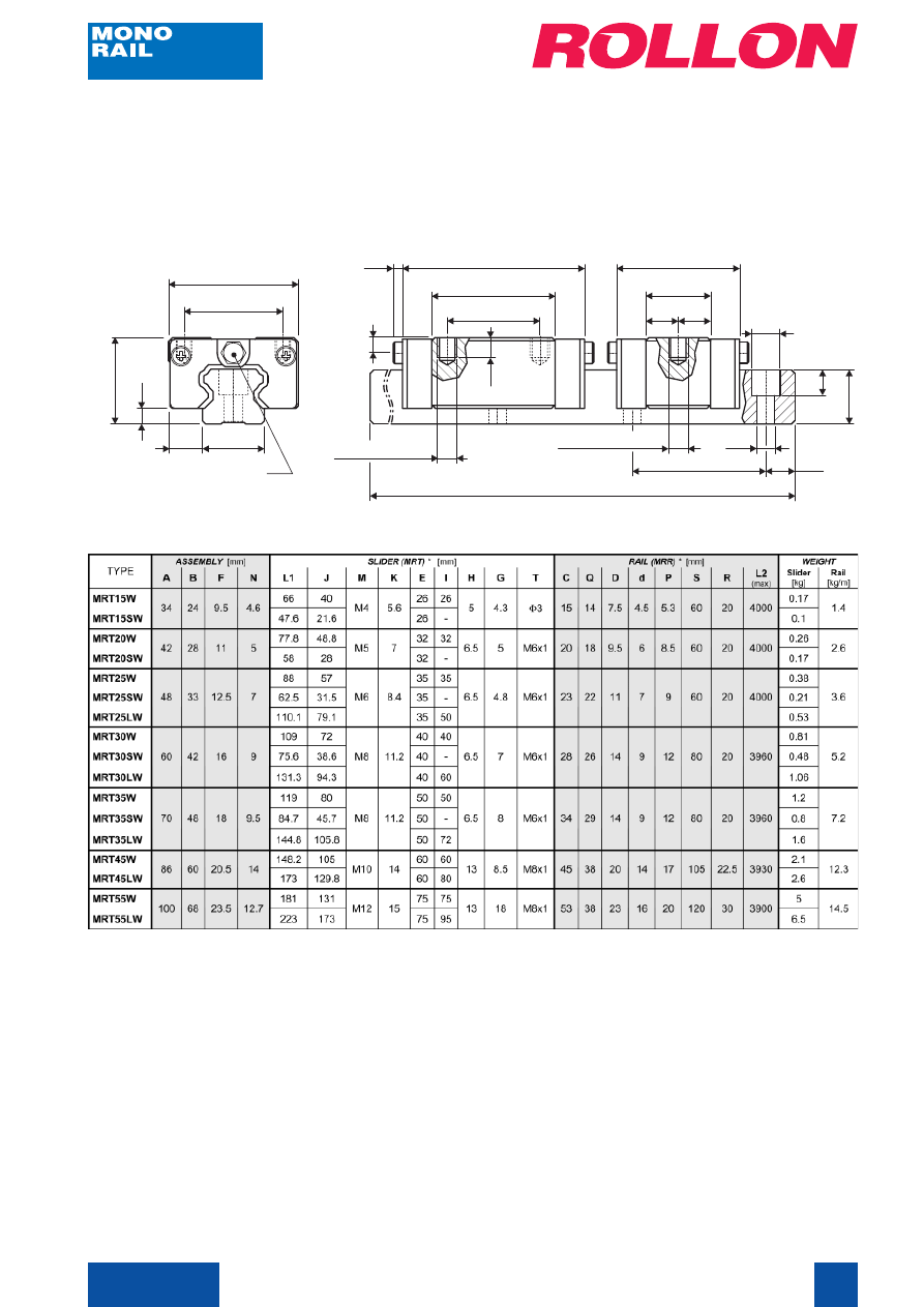
TECHNICAL DATA
MRT Series (with flange)
Cat. 41-42E
9
A
B
C
N
E
F
G
M
(n°4 holes)
H
I
J
K
L1
M
(n°2 holes)
=
=
J
L1
* For order codes see page 17
φφφφφ
D
φφφφφ
d
S
(holes pitch)
R
P
Q
L2
max
TECHNICAL DATA
MRT Series (without flange)
T
(grease nipple)
Threaded holes version
Cat. 41-42E
10
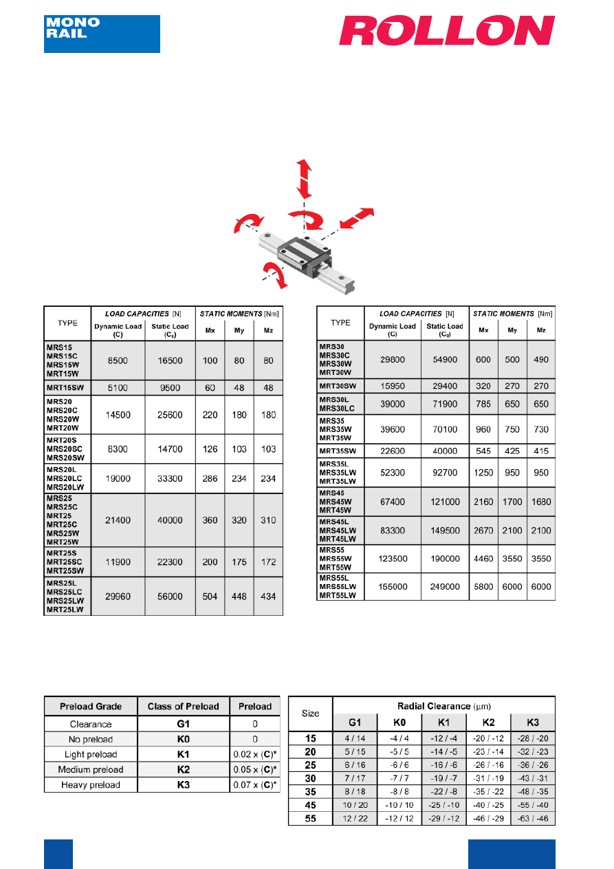
LOAD CAPACITIES
In the table below are indicated load capacities for each slider type.
Axial and radial static capacity loads are the same. This is true because of the 4-rows circular
contact ball recirculating system (45° contact angles). For more information, please contact our
Application Engineering Department.
C
0
Mx
Mz
My
C
0
PRELOAD / RADIAL CLEARANCE
In the table below classes of preload and radial clearance of the sliders are indicated.
*
(C) is the dynamic load capacity indicated in the load capacity
table above.
Cat. 41-42E
11
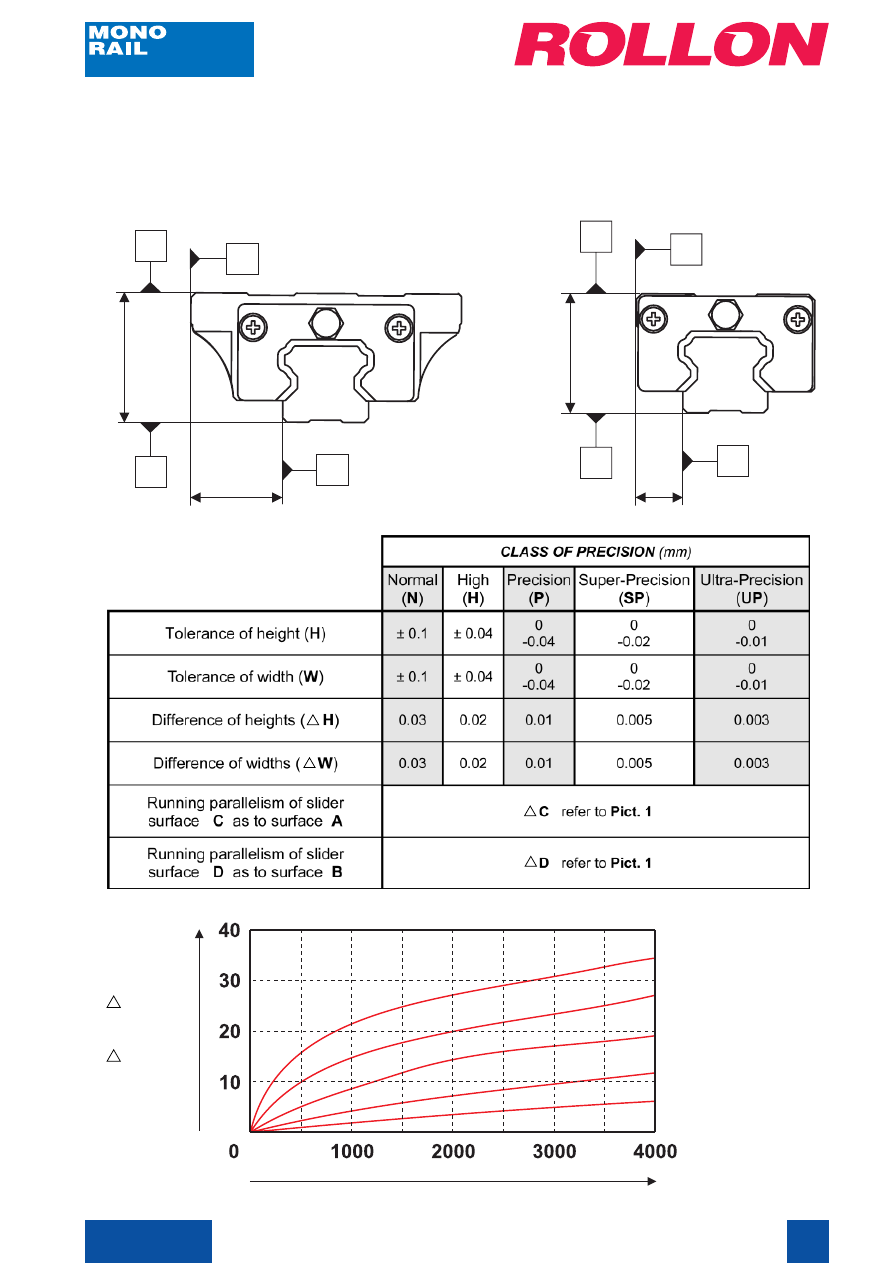
LINEAR PRECISION
C
D
A
W
B
H
C
D
A
W
B
H
Rail length (mm)
C (
µ
m)
D (
µ
m)
Linear precision means the running parallelism of the slider, i.e. the maximum deviation of the
slider, referred to the lateral surface and to the supporting one, during its run along the rail.
Normal (N)
High (H)
Precision (P)
Super-precision (SP)
Ultra-precision (UP)
Pict. 1
Cat. 41-42E
12
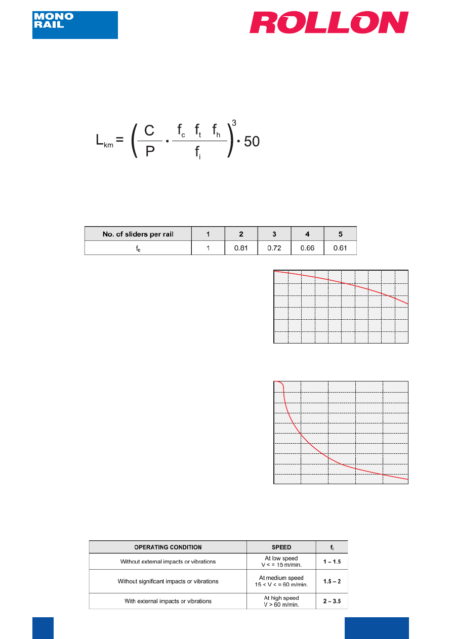
LIFETIME
LIFE CALCULATION:
The dynamic load rating C is a conventional load rating used in life calculations. The life to
which this load rating is here related is 50 km. Life L
km
(in km), load rating C (in Newton) and the
applied external load P (in Newton) are related to each other by the formula:
Hardness factor f
h
The optimum load capacity can be reached when
the raceways hardness is 58 to 64 HRc.
If the raceways hardness is lower than 58 HRc,
the load rating C must be multiplied by hardness
factor f
h
indicated in the table nearby.
Temperature factor f
t
When the system temperature is higher than
100 °C, temperature factor f
t
has a significant
value (lower than 1).
Temperature close raceways (°C)
Contact factor f
c
The factor f
c
refers to applications where more than one slider pass over the same point on the
rail. In ball recirculating systems is difficult to obtain a uniform load distribution because of the
mounting surfaces precision. When two or more sliders are acting over the same points of the
rail, we need to multiply static and dynamic load rating by the figures in the table below:
Service factor f
i
Service factor f
i
has a meaning similar to the safety factor used in the ‘Verification under static
load’ and the values are indicated in the table below:
Note 1: above 80°C, seals and end plates should be designed
for high temperature operations.
Note 2: above 120°C, special treatments shoud be designed
for stabilizing the dimensions.
where:
fc
= contact factor
ft
= temperature factor
f h
= hardness factor
fi
= service factor
Temperature factor
f
t
Hardness of raceway (HRc)
Hardness factor
f
h
1.0
0.9
0.8
0.7
0.6
0.5
100
150
200
50
40
30
20
10
60
0.9
0.8
0.7
0.6
0.5
0.4
0.3
0.2
0.1
1.0
Cat. 41-42E
13
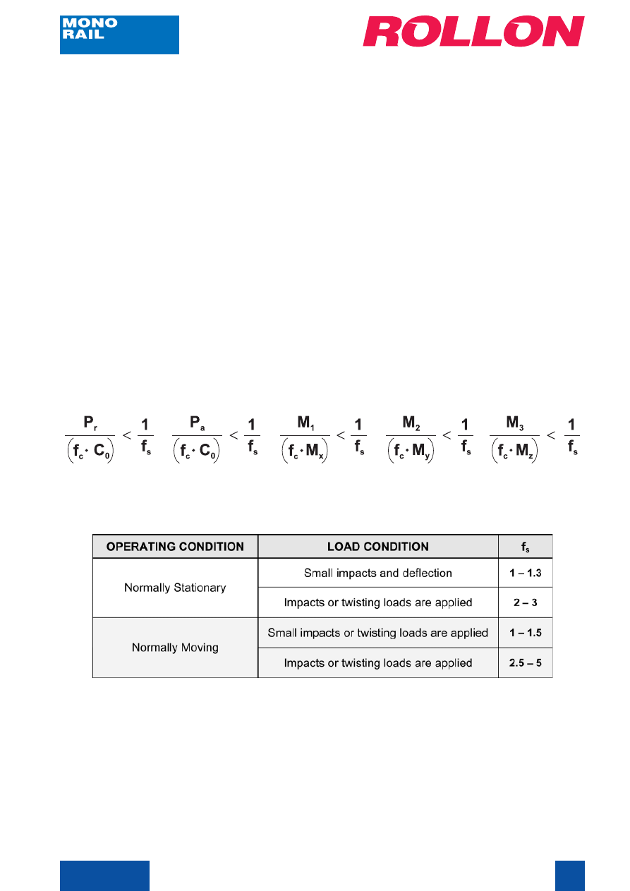
VERIFICATION UNDER STATIC LOAD
CALCULATION:
The values of static load rating given on page 10 for each slider, represent the maximum allowable
loads, above which a permanent deformation of the raceways could occur and consequently the
running quality could be compromised.
The verification is made:
- by calculating the forces and the moments acting simultaneously on each slider
- by comparing these values with the corresponding load ratings
If:
P
r
, P
a
are the radial and axial resultants of the external forces, in Newton;
M
1
, M
2
, M
3
are the external moments, in Nm;
C
0
, M
x
, M
y
, M
z
are the load ratings in the various directions, given on page 10;
f
s
is the safety factor (see table below);
f
c
is the contact factor (see table on page 12);
the result should be:
Values of the safety factor f
s
:
The safety factor f
s
should be lowest when the dynamic forces to be added to the loads can be
determined accurately, and higher when overloads may occur, especially dynamic loads such
as shocks and vibrations.
Please contact our Application Engineering Department if further information is required.
Cat. 41-42E
14
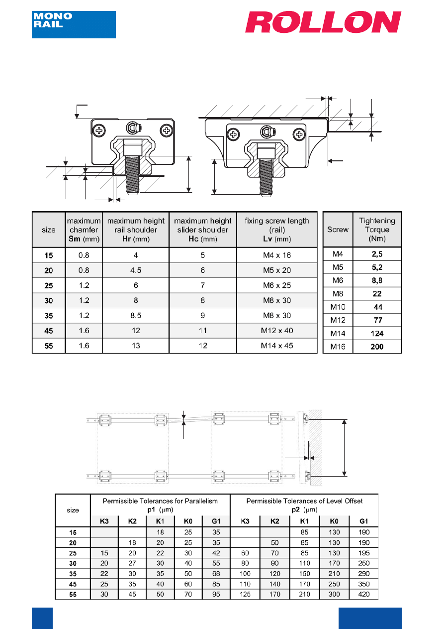
MOUNTING METHODS
In the tables below are indicated the types of screw to be used and the optimum tightening
torques for rails mounting.
MOUNTING PRECISION
In the drawing and table below the maximum allowable errors of the rails mounting surfaces are
indicated.
ground surface
Sm
ground
surface
Sm
Hc
Lv
Lv
Sm
Hr
Sm
p1
p2
500
mm
Cat. 41-42E
15
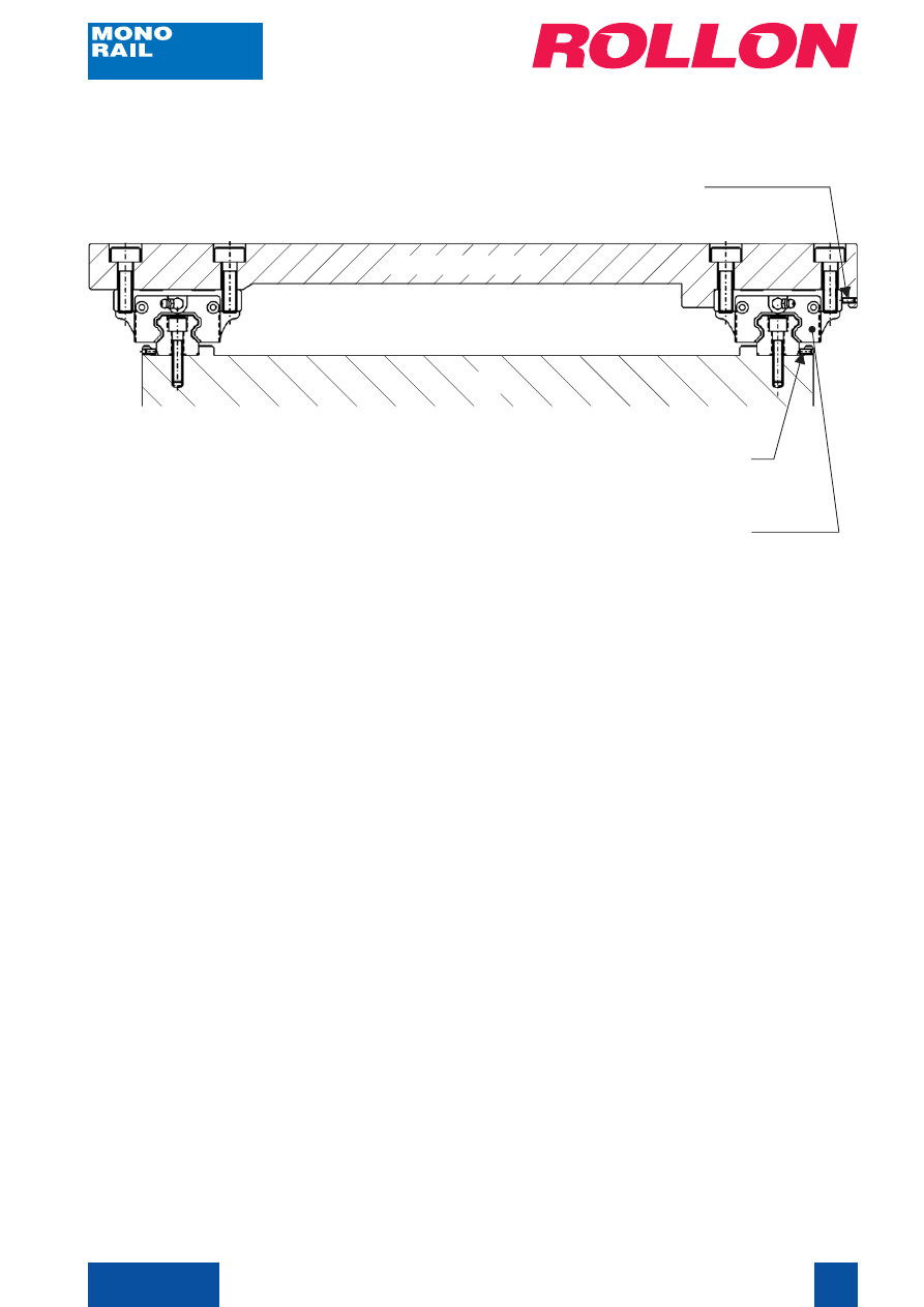
MOUNTING PROCEDURE
INSTRUCTIONS:
1. Remove dents, burrs and dirt on mounting surfaces;
2. Place rail against the shoulder of mounting surfaces;
3. Tighten the mounting bolts lightly (check that holes on rail are aligned with the screw holes on
mounting surfaces). Do not tighten a bolt if the holes are not aligned;
4. Tighten the rail set screws;
5. When tightening the mounting bolts, start with the bolt at the longitudinal center of the rail and
move towards both rail ends;
6. Mount the other rail in the same way (from point 1. to 5.);
7. Install caps in unused mounting holes;
8. Place the table on the blocks carefully, checking the screw holes alignement;
9. Tightening the block set screw to position the table;
10. Tighten the mounting bolts on the master and subsidiary blocks (the mounting bolts should
be tightened in the diagonal sequence);
Note: Accuracy of master rail depend on the accuracy of shoulder and datum plane of frame.
slider / reference side
MOBILE TABLE
BASE
set screw (rail)
set screw (slider)
Cat. 41-42E
16
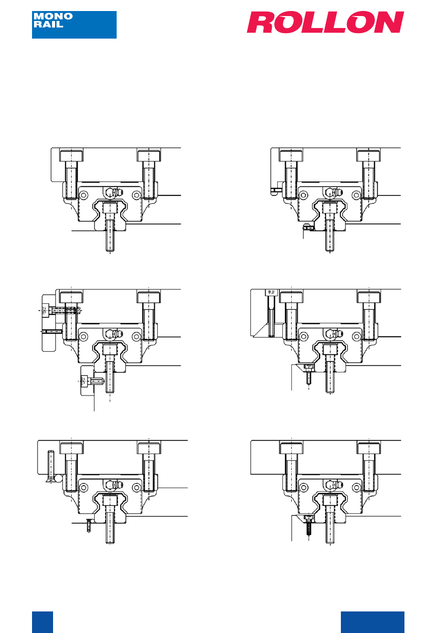
FIXING EXAMPLES
In the drawings below some rail/slider fixing examples, following the structure type to which they
are joined, are indicated.
Example 1
Example 3
Example 5
Example 2
Example 4
Example 6
Cat. 41-42E
17
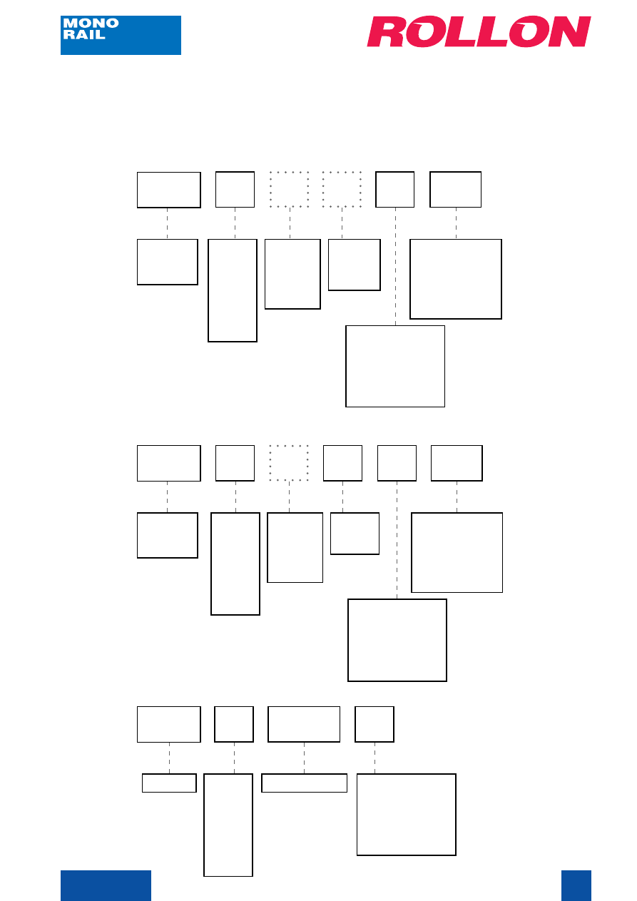
ORDER CODES
The rails and sliders order codes are listed below. Rails and sliders must be ordered separately.
Slider (with flange):
MRS
20
slider type:
MRS
MRT
size:
15
20
25
30
35
45
55
L
option*
slider
length:
L (long)
S (short)
C
option*
with
cylindrical
holes
H
class of precision:
N (normal)
H (high)
P (precision)
SP (super-precision)
UP (ultra-precision)
K1
class of preload:
G1
K0
K1
K2
K3
* When these letters are not inserted, slider will be
supplied with standard length and threaded holes.
Slider (without flange):
MRT
45
slider type:
MRS
MRT
size:
15
20
25
30
35
45
55
S
option*
slider
length:
L (long)
S (short)
W
version
without
flange
P
class of precision:
N (normal)
H (high)
P (precision)
SP (super-precision)
UP (ultra-precision)
K1
class of preload:
G1
K0
K1
K2
K3
* When this letter is not inserted, slider will be
supplied with standard length.
Rail:
MRR
35
rail type
size:
15
20
25
30
35
45
55
1240
rail length
N
class of precision:
N (normal)
H (high)
P (precision)
SP (super-precision)
UP (ultra-precision)
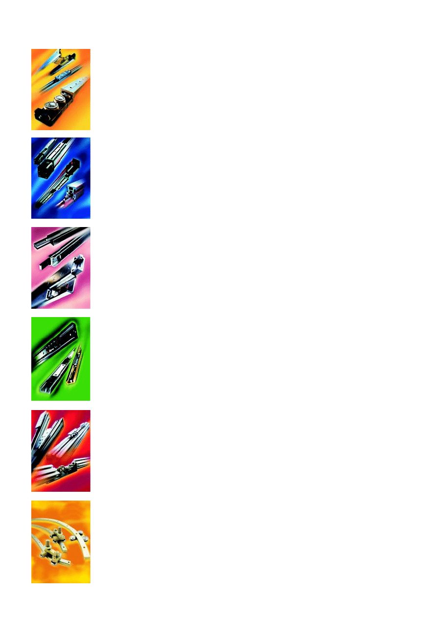
More product families:
COMPACT RAIL has all of the characteristics that distinguishes ROLLON’s whole
product line: originality, innovative designs, compactness, smooth movement, and
ease of use. The T+U and K+U rail systems can be mounted on non-machined
surfaces and can even compensate for mounting surface parallelism inconsistencies.
This flexibility allows the design engineer to focus more time and energy on the
application itself and not on the components while saving large amounts of mounting
time and, therefore, money. All COMPACT RAIL sliders have radial ball bearing rollers,
which provide smooth and fast movement.
COMPACT RAIL:
World’s most versatile roller slider system
ROLLON’s TELESCOPIC RAIL family improves upon all of the characteristics that
made our Heavy Duty family of rails well known. Design improvements on existing
products and the addition of new ones will allow ROLLON’s extended family of
telescopic rails to remain the industry leader.
The TELESCOPIC RAIL family offers various types of slides which means that a design
engineer can easily find an original solution for each application. All of the products
have innovative, problem-solving designs and are built to extend heavy loads out
from their mounting structure with little or no deflection.
TELESCOPIC RAIL:
Industrial telescopic rails
The simple but extremely versatile design of the rails in this family is the characteristic
that defines their success. Made from cold-drawn steel with internal, hardened
raceways like most of ROLLON’s products, these slides are made for 24 hours a
day industrial use. With high load and moment capacities, EASY RAIL linear bearings
are known for their high quality, affordability, ease of movement, and compactness.
EASY RAIL:
Strong and easy linear solution
ECOLINE:
Affordable and innovative linear bearings
ECOLINE’s products have been designed to fit in applications where quality movement
is needed but high prices are not. The patented design offers a wellprotected, smooth
slide that is easily and quickly mounted. ECOLINE combines the quality associated
with all of ROLLON’s products with the affordability needed in application sectors
like industrial protective panels, vehicle slides, and machine tool doors. ECOLINE is
the answer to labor intensive, homemade solutions, cheap bent steel slides, or
expensive, overdesigned round or profiled shafting.
ROLLON’s CURVILINE is the cost effective linear solution for applications with linear
movement that isn’t always strictly linear.
CURVILINE is a custom solution made according to your application’s needs.
The system is composed of one or more sliders and a zinc-plated rail. The sliders
have multiple radial ball bearings mounted to them providing the movement and
carrying the load.
Two versions are available: one with a constant radius, and one with a variable
radius which can be composed of both straight and curved sections. Each version
has its own specific slider which is designed to uniformly follow the rail without
modification to its preload. All sliders are have radial ball bearings which are lubricated
for life and offer long life due to their hardened raceways.
CURVILINE:
High flexibility curvilinear rails
A complete family of belt-driven linear actuators designed to run in real-world
applications. Based on COMPACT RAIL, these compact units are versatile, fast, and
well protected. With designs for every application, UNILINE offers “personalized”
actuators with high load capacity, high stiffness and rigidity, and all in a very compact,
high quality package. With tee-slots and standard accessories, this family is as
modular and versatile as it is innovative.
UNILINE:
Linear units with roller sliders

...where you can find MONO RAIL:
www.rollon.com
While every care has been taken in the manufacture of this catalog, we apologize for any errors or omissions it may contain.
Data and characteristics indicated in the catalogue may be varied without notice.
Even partial reproduction is allowed only by written permission.
Headquarters:
ROLLON S.p.A.
Via Trieste, 26 - 20059 Vimercate (MILANO) - ITALY
Phone: (+39) 039 62591 - Fax: (+39) 039 6259205
e-mail: infocom.it@rollon.com
Sales companies and Partners:
ROLLON B.V.
Edisonstraat 32b
NL-6902 PK Zevenaar - Holland
phone: (+31) 316 58 19 99
fax: (+31) 316 34 12 36
e-mail: info@rollon.nl
HAUDENSCHILD AG
Hummelbergstrasse 11
Postfach 1529
CH-8640 Rapperswil-Jona - Switzerland
phone: (+41) 055 225 40 50
fax: (+41) 055 225 40 60
e-mail: haud@haudenschild.com
ROLLON GmbH
Industriegebiet Voisweg
40878 Ratingen - Germany
phone: (+49) 2102 8745 0
fax: (+49) 2102 8745 10
e-mail: info@rollon.de
ROLLON S.R.O.
Na Máchovnè 1270
CZ-26604 Beroun - Czech Rep.
phone: (+420) 311 61 00 50
fax: (+420) 311 61 00 53
e-mail: info@rollon.cz
ROLLON S.A.R.L.
8, rue Paul Valérien Perrin
Z.I. de la Tuilerie
38170 Seyssinet - France
phone: (+33) 04 38 12 05 22
fax: (+33) 04 38 12 16 33
e-mail: infocom@rollon.fr
S.R.O ASSI SA
Centro GTL, CP47
CH-6929 Gravesano - Switzerland
phone: (+41) 91 612 22 80
fax: (+41) 91 612 22 89
e-mail: sro.assi.sa@bluevin.ch
Wyszukiwarka
Podobne podstrony:
41 42 43 id 38542 Nieznany (2)
41 3 id 38500 Nieznany
41 15 id 38540 Nieznany
41 id 38495 Nieznany
pkm projekt5 41 id 360112 Nieznany
41 5 id 38503 Nieznany (2)
cw 41 id 122430 Nieznany
GG 2007 2 41 id 190133 Nieznany
Abolicja podatkowa id 50334 Nieznany (2)
4 LIDER MENEDZER id 37733 Nieznany (2)
katechezy MB id 233498 Nieznany
metro sciaga id 296943 Nieznany
perf id 354744 Nieznany
interbase id 92028 Nieznany
Mbaku id 289860 Nieznany
Probiotyki antybiotyki id 66316 Nieznany
miedziowanie cz 2 id 113259 Nieznany
LTC1729 id 273494 Nieznany
więcej podobnych podstron