
Chapter V
FIRE SUPPORT
1. Background
This chapter focuses on the force
multiplier of fire support. It defines fire
support and related terms to establish a
common point of reference for subsequent
discussions. It also highlights diverging
service perspectives on selected fire support
coordinating measures and offers fire support
TTP to support
integrated combat
operations.
2. Terminology
a. Fire Support. The term “fire support”
is not defined in approved joint doctrine.
Service publications define it as follows:
(1) Army. FM 100-5, Operations,
defines fire support as “the collective and
coordinated employment of the fires of armed
aircraft, land- and sea-based indirect fire
systems, and electronic warfare systems
against ground targets to support land
combat operations at both the operational and
tactical levels. Fire support is the integration
and synchronization of fires and effects to
delay, disrupt, or destroy enemy forces,
combat functions, and facilities in pursuit of
operational and tactical objectives. ”
(2) USMC. FMFRP 0-14, Marine
Corps Supplement to the DOD Dictionary of
Military and Associated Terms, defines fire
support as “assistance to elements of the
MAGTF engaged with the enemy rendered by
other firing units, including (but not limited
to) artillery, mortars, naval surface fire
support, and offensive air support.”
(3) Proposed Joint Definition. Given
the general Army-Marine Corps definition
consensus reflected above, this text defines
fire support as the collective and coordinated
use of indirect-fire weapons, armed aircraft,
sea surface fires, and other lethal and
disruptive means in support of a battle plan.
b. Supporting Arms. Joint Pub 1-02
defines supporting arms as “air, sea, and
land weapons of all types employed to support
ground units.” FMFRP 0-14 proposes a
modification that reads “weapons systems of
all types employed to provide fires to the
commander.”
c. Firepower. Joint Pub 1-02 defines
firepower as “the amount of fire which may
be delivered by a position, unit or weapon
system; the ability to deliver fire.” The
Universal Joint Task List cites employ
firepower as a fundamental operational task.
Conceptually, employ firepower means “to
apply the amount of fire which may be
delivered by joint forces through all available
means and systems. The collective and
coordinated use of target acquisition data,
direct and indirect fire weapons, armed
aircraft of all types, and other lethal and
nonlethal means against ground targets in
support of JFC objectives. This task includes,
artillery, mortar, and other non line-of-sight
fire, naval gunfire, close air support, and
electronic countermeasures. It includes strike,
air defense, antiair/surface/subsurface defense
and naval surface fire support, counterair,
and air interdiction. Firepower includes all
types of ordnance. ”
3. Fire Support Coordinating Measures
The Army and Marine Corps recognize
and use a common set of FSCM intended to
expedite the attack of targets, protect the
force, safeguard noncombatants and sites of
religious or cultural significance, preserve
infrastructure, and set the stage for future
operations. Two notable exceptions include
differing service interpretations of the fire
support coordination line (FSCL) and NFA
as discussed below. Accordingly, operations
plans and orders must clearly articulate the
intent regarding use of these two particular
FSCM.
V-1

a. FSCL. In defining the FSCL, Joint
Pub 1-02 states: “Supporting elements may
attack targets forward of the fire support
coordination line without prior coordination
with the ground force commander provided
the attack will not produce adverse effects on
or to the rear of the line.” The Army inter-
prets the term “supporting element”
(undefined as a joint term) to mean
subordinate elements. For example, elements
subordinate to a corps may fire beyond a
corps established FSCL irrespective of
boundaries; adjacent units from another
corps may not. The Marine Corps interprets
supporting elements to mean an element of a
supporting force as defined in Joint Pub
1-02 rather than a subordinate element. The
Marine Corps subscribes to the Joint Pub
3-O, Doctrine for Joint Operations, description
of the FSCL as a permissive fire support
coordinating measure established by
commanders to ease coordination require-
ments for attack operations within their area
of operations by forces not under their
control, such as naval gunfire or air
interdiction and that it applies to all superior,
subordinate, supporting, and other affected
commanders. Joint Pub 3-O includes an
expansive discussion on the FSCL and
provides the following amplifying guidance:
“Forces attacking target beyond an FSCL
must inform all affected commanders in
sufficient time to allow necessary reaction to
avoid fratricide, both in the air and on the
ground . . . . Coordination of attacks beyond the
FSCL is especially critical to commanders of
air, land, and special operations forces. Their
forces may now be operating beyond an FSCL
or may plan to maneuver on that territory in
the future. Such coordination is also
important when attacking forces are
employing wide area munitions or munitions
with delayed effects.
Finally, this
coordination assists in avoiding conflicting
or redundancy attack operations. In
exceptional circumstances, the inability to
conduct this coordination will not preclude
the attack of targets beyond the FSCL.
However, failure to do so may increase the risk
of fratricide and could wastes limited
resources.
y
b. No Fire Area, Marine Corps doctrine
states that “typically the host country
establishes an NFA. On arrival of military
forces, the force commander coordinates the
location of an NFA with local authorities.”
In Army doctrine, tactical units—normally
corps or divisions—establish NFAs.
4. A Common Perspective
Great commonality exists when viewing
Army and Marine Corps perspectives on fire
support, particularly regarding field artillery
(artillery in Marine terminology) doctrine,
tactics, and employment principles. The
discussions that follow explore areas where
those perspectives diverge and offer
recommendations on how the JFC can
effectively employ fire support to support
intent and concept of operations.
5. DRB Fire Support Operations
Field artillery units provide cannon,
rocket, and missile fires in support of
designated commanders and operations as
directed. Field artillery commanders and fire
support agencies at corps through company
levels advise and assist respective maneuver
commanders with integrating, coordinating,
and executing all means of available fire
support to support combat operations.
a. Field Artillery Command Structure.
Field artillery is organized at corps, division,
and brigade levels with a specific command
and control structure that enables the field
artillery commander to accomplish dual
responsibilities as a FSCOORD and an
artillery commander. There is a field artillery
headquarters and headquarters battery
(HHB) in each corps artillery, division
artillery, field artillery brigade, and each
close support field artillery battalion such as
the DRB’s supporting artillery battalion. At
each level, the HHB provides both a CP for
the command and control of field artillery
units and the nucleus of a FSE that operates
as part of the supported maneuver CP. Both
are supervised on a full-time basis by the
field artillery commander’s designated
representatives. S3 operations officers
V-2
normally run the artillery CPs; deputy fire
support coordinator (DFSCOORD) at corps
and division levels and fire support officers
(FSOs) at brigade level and below supervise
FSEs. Table V-1 depicts Army fire support
coordination organizations and FSCs from
corps down to company levels.
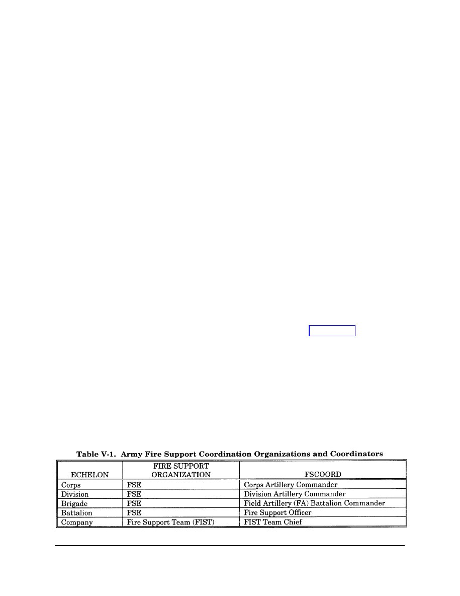
b. DRB Fire Support Coordination
Organizations and Coordinators. The
commander of the DS artillery battalion also
functions as the brigade FSCOORD. The
commander of the DS artillery battalion
establishes a fire support section comprised
of a FSO, fire support noncommissioned officer
(NCO), and several fire support specialists
that operate from an M577 CP vehicle as part
of the brigade’s main CP. The fire support
section serves as the nucleus of the brigade’s
FSE. Additional members of the FSE may
include an Air Force ALO, a Marine air and
naval gunfire liaison company (ANGLICO)
supporting arms liaison team (SALT), an
engineer representative, a chemical officer,
and the S3 air. Each maneuver battalion
tactical operations center features a similarly
configured FSE. The FIST coordinates fire
support at the company level. A FIST
headquarters supports each company of a
tank battalion. The FIST for the mechanized
infantry battalion consists of a FIST
headquarters (FIST chief serves as company
FSO) and 3 forward observer (FO) parties per
company. Although FSEs and FISTs are
organic to artillery organizations, once
deployed they remain with supported
maneuver units regardless of the tactical
missions assigned to their parent artillery
units. FISTS operate from the M981 fire
support team vehicle (FIST-V) equipped with
the ground/vehicular laser locator designator
(G/VLLD); FO parties operate with and are
transported by their supported maneuver
platoons. Figure V-1 illustrates the DRB’s
supporting fire support coordination
organizational structure. Also depicted are
the brigade’s 3 combat observation and
lasing teams (COLTs). COLTs do not serve
a specific fire support coordination function;
however, because they are valuable assets
designed to maximize the brigade’s
employment of smart munitions, command
and control of the COLTS is normally
retained at the brigade level.
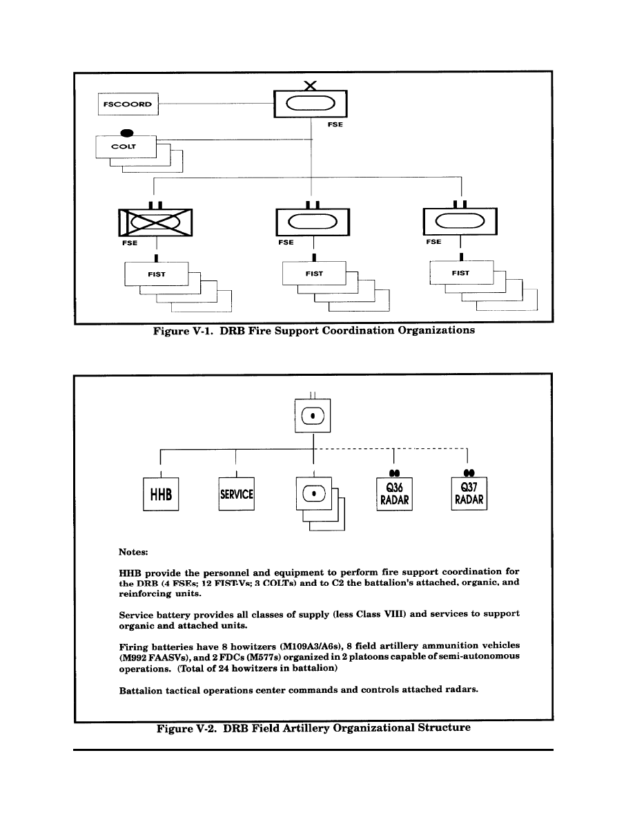
c. DRB Fire Support Attack Assets.
(1) Field Artillery. Each committed
maneuver brigade in the USA has a
habitually associated field artillery battalion
in direct support. Although the DRB
currently receives its direct support artillery
fires from an M109A3-equipped howitzer
battalion, that battalion will transition to the
M109A6 “Paladin” howitzer. In either case,
the MLRS battery (if attached as assumed
for the purposes of this publication) provides
reinforcing fires. Figure V-2 depicts the
DRB’s supporting field artillery organization.
(a) M109A6 “Paladin” Howitzer.
The Paladin affords the force a more
responsive, longer range, more survivable,
and easily maintainable cannon system than
its predecessor, the M109A3. An automatic
fire control system includes position
V-3
V-4
navigation and a ballistic computer that does
on-board technical fire direction that enables
it to respond to calls for fire in less than 2
minutes. Its range advantage over the
M109A3 is 23.1 to 18.5 km for unassisted
projectiles and 30 to 23.5 km for rocket
assisted projectiles. Because the Paladin can
rapidly occupy a firing position, shoot, and
displace, its vulnerability to counterfire is
significantly reduced.
(b) Multiple
Launch Rocket
System (MLRS). The MLRS is a highly
mobile, rapid-fire, surface-to-surface, free-
flight rocket, and guided missile system
designed to complement cannon artillery to
attack the enemy deep and to strike at
counterfire, air defense, and high payoff
targets.
“Capabilities. MLRS provides
the commander with a significant capability
for executing counterfire, interdiction, and
assisting in SEAD. The MLRS is well suited
for attacking large area targets; recom-
mended target sets include personnel, self-
propelled artillery, air defense systems,
infrastructure and lightly protected combat,
combat support, and CSS systems. To
support deep operations, the Army Tactical
Missile System (ATACMS) capable MLRS
battery provides the JFC the capability to
attack high payoff targets at ranges from 25
to 165 km. The system can also assist in joint
suppression of enemy air defenses (J-SEAD)
to support air interdiction and/or deep
operations.
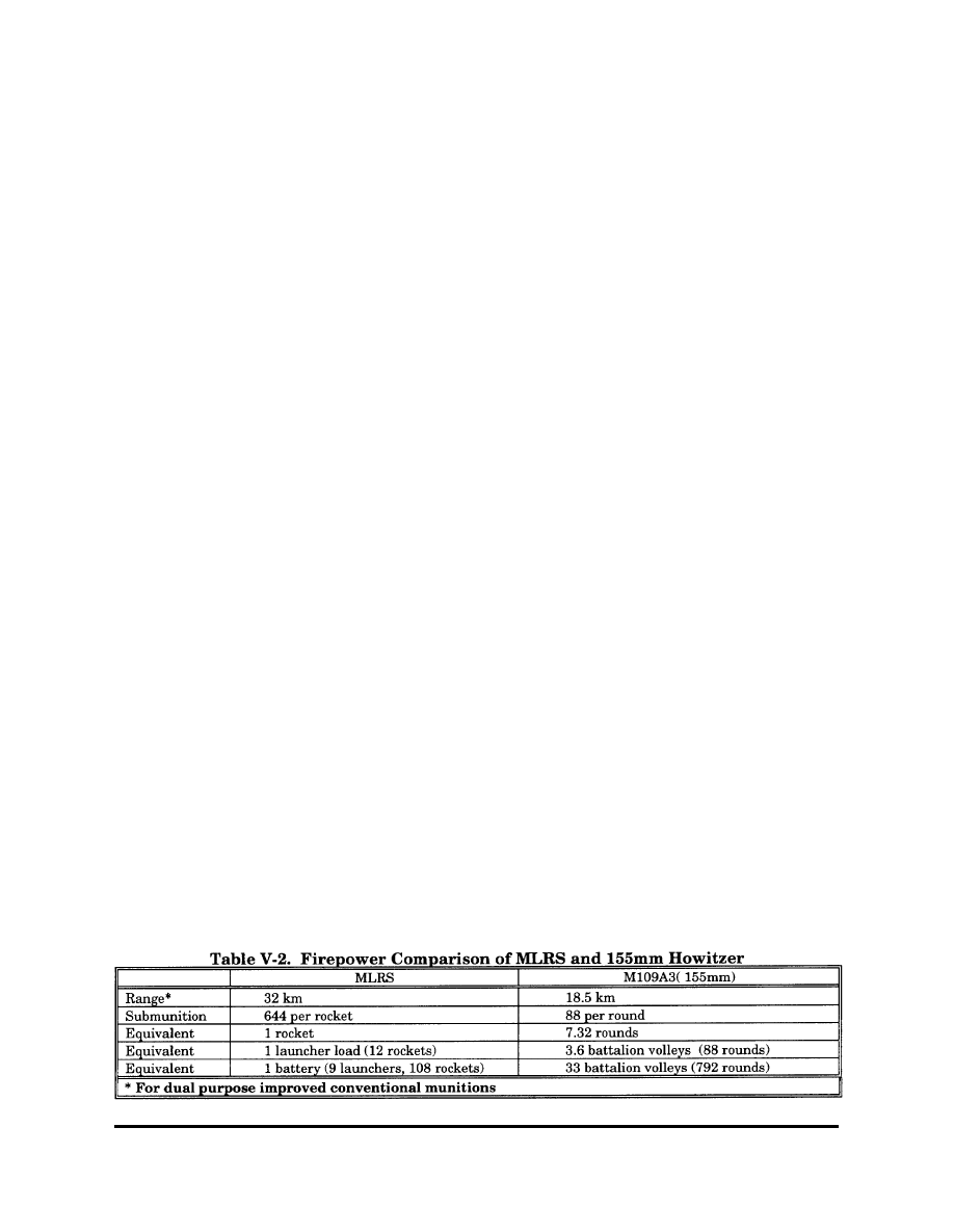
• Firepower. The firepower
comparison between the MLRS and the
155mm howitzer shown in Table V-2 reflects
the increased attack potential that MLRS
provides the joint force.
• Interoperability. The MLRS
interfaces with many types of command and
control systems. The fire direction center at
platoon, battery, and battalion levels can
interface directly with the Tactical Fire
Direction System
(TACFIRE), light
TACFIRE (LTACFIRE), the Interim Fire
Support Automation System (IFSAS), digital
message devices, other FDCs, the Cannon
Battery Computer System (BCS), the
AFATDS, the Airborne Target Handover
System (ATHS), and the GSM—the ground
link to J-STARS.
• System Characteristics. MLRS
features an on-board, self-location, direc-
tional control, ballistic computation, and
digital communications system in one piece
of equipment. The system consists of M270
launchers; launcher pods; ammunition
resupply vehicles and trailers; and a
command, control, and communications
system. Each launcher has the on-board
capability to receive a fire mission, self-
locate, compute firing data, orient on the
target, and deliver up to 12 rockets, All 12
rockets can be fired in less than 60 seconds
at single or multiple aimpoints. Rockets can
be fired individually or a designated number
can be fired at specified intervals. To improve
response time and facilitate target
engagement, the MLRS interfaces directly
with target acquisition assets.
V-5
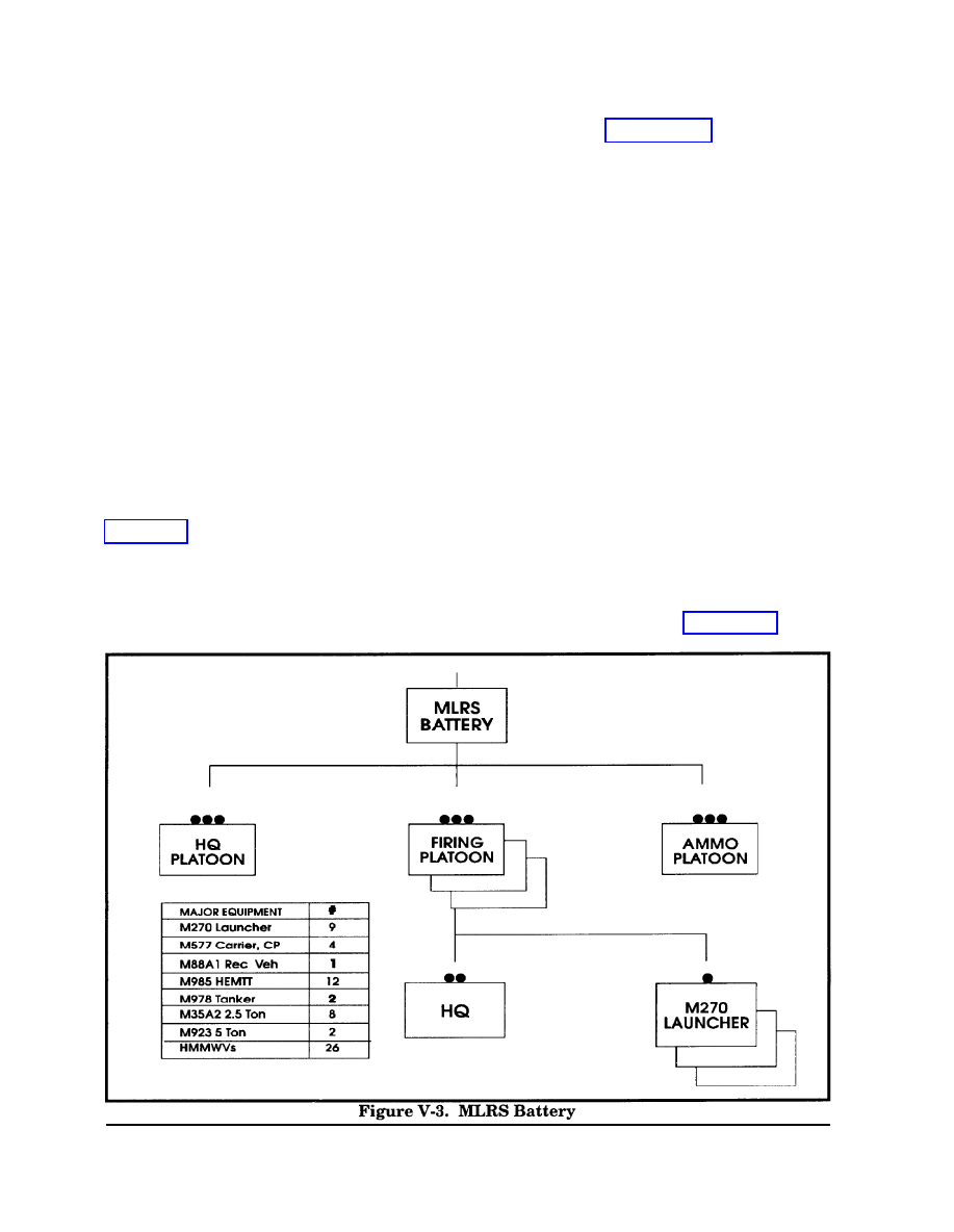
• Ammunition Resupply. Ammu-
nition resupply of the battery’s 9 launchers
occurs with the 12 M985 heavy expanded
mobility tactical trucks (HEMTTs) and 12
M989A1 heavy expanded mobility
ammunition trailers (HEMATs) assigned to
the battery’s ammunition platoon. Each
HEMTT/HEMAT combination can carry 48
rockets (8 pods).
• Organization. Figure V-3
depicts the organizational structure of the
DRB’s supporting MLRS battery.
(2) Mortars. Each of the DRB’s 3
ground maneuver battalions features a
company of 6 120mm mortars. The company
provides dedicated, immediately responsive
fires in support of battalion/task force
operations.
(3) Electronic Warfare Assets.
Chapter III described DRB electronic warfare
systems and assets capabilities.
(4) USAF Air Support. USAF fixed-
wing air support is coordinated through the
corresponding tactical air control parties
(TACPS). See Chapter VII for additional
discussion.
(5) Naval Support. See paragraph 7
C
for naval surface fire support and naval air
support of DRB operations.
d. DRB Target Acquisition Assets. The
DRB features a variety of target acquisition
assets ranging in scope from the FISTS, to
access, to national-level collection assets. As
reflected in Figure V-1, the DRB has a full
complement of FISTS attached to the
maneuver companies and 3 COLTS available
for employment at brigade level. An AN/
TPQ-36 weapons-locating radar may support
the artillery battalion’s operations; target
acquisition range more than doubles (from
24 to 50 km) if the AN/TPQ-37 weapons-
locating radar is available for support. The
DRB may also have aerial assets (OH-58D
helicopters) from supporting Army aviation
units. Finally, the brigade has a direct link
to targeting intelligence developed by higher
headquarters through the intelligence
brigade and battalion ALOs/S3 air and
architecture described in Chapter III.
V-6
6. Army Aviation
The DRB may be augmented by Army
aviation assets as described in Chapters I
and VII. Attack helicopters are most
effective when employed in mass (battalions
or companies) in an air maneuver role
against enemy armor or artillery formations
or against other high payoff combat, combat
support, or CSS target sets. The division’s
aviation brigade’s primary mission is engage
and destroy threat armored and mechanized
forces. When necessary, Army aviation can
provide fire support for ground maneuver
units, coordinate and adjust indirect fires,
conduct joint air attack team operations, and
command and control deep operations.
7. MEF (FWD) Fire Support Operations
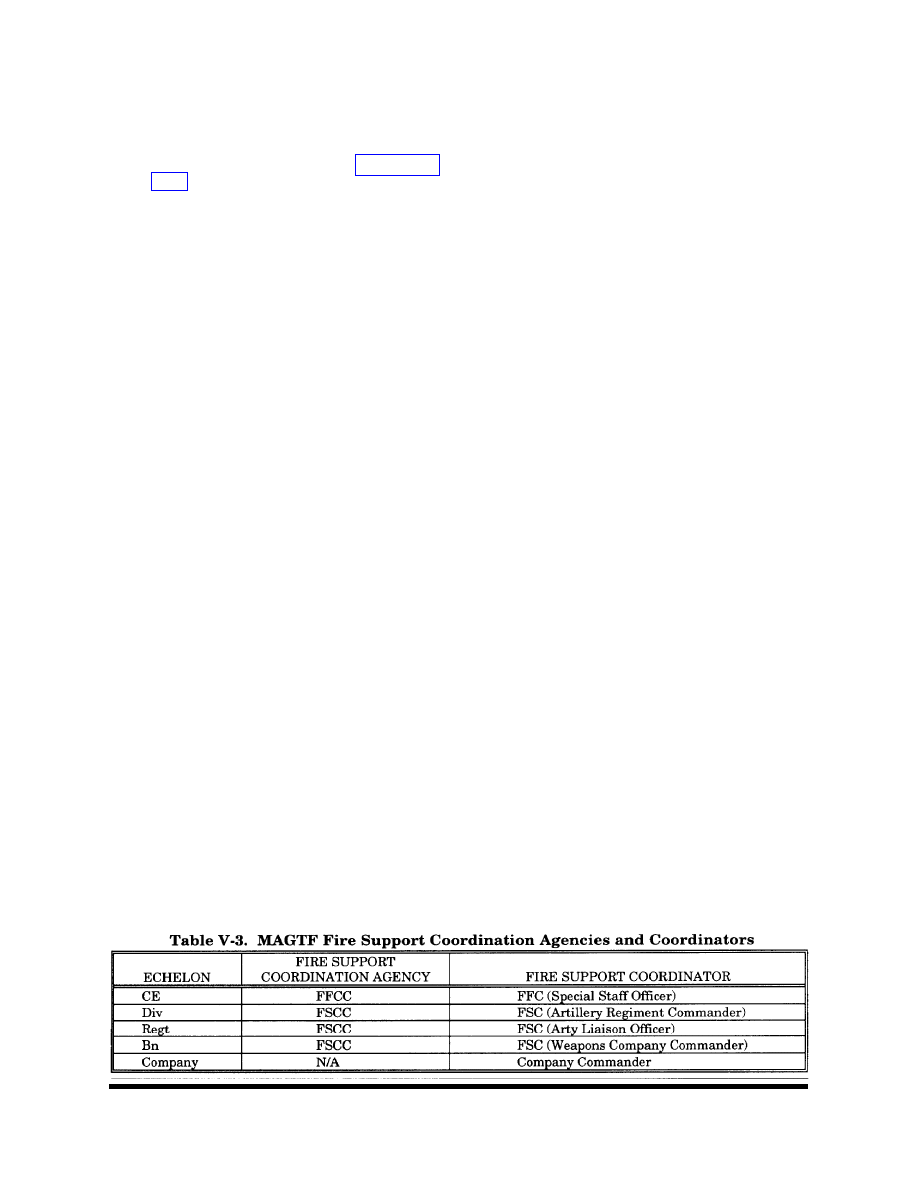
a. MEF (FWD) Fire Support Coordi-
nation Agencies and Coordinators. MEF
(FWD) fire support coordination agencies
include the FFCC at the MEF (FWD) CE and
FSCCs at each battalion level and higher
maneuver force of the GCE. All agencies are
staffed with representatives of the various
supporting arms. A force fires coordinator
(FFC) directs the operations of the FFCC;
fire support coordinators (FSCs) exercise
responsibility
for respective FSCC
operations. Once established, FSCCs
coordinate directly with FSCCs of adjacent
and higher units. Table V-3 details MAGTF
fire support coordination agencies and
coordinators from MEF to company levels.
(1) MEF (FWD) FFCC. The MEF
(FWD) commander task organizes the FFCC
with the personnel, equipment, and commu-
nications required to support operational
requirements. The MEF (FWD) FFCC plans
fires to support deep operations, participates
in planning joint deep operations, and
coordinates those operations with GCE close
operations through the GCE FSCC. The GCE
FSCC identifies and submits additional fire
support requirements in the form of targets
and requests for reinforcing fires to the MEF
(FWD) FFCC. The MEF (FWD) FFCC
receives the GCE’s target nominations and
coordinates the GCE’s requests for fire
support from external agencies (e.g.,
coordinating Army MLRS mission support for
the GCE). The MEF (FWD) FFCC also
coordinates ACE and CSSE fire support
requirements, including SEAD and fire
support for rear operations respectively.
(2) GCE FSCC. The GCE commander
employs FSCC to conduct fire support
coordination. The GCE FSCC plans fires,
conducts targeting, and integrates deep
supporting fires with maneuver. Close
supporting fires require detailed integration
and coordination and are primarily the
concern of lower echelons. To enable the
efficient employment and coordination of
Marine aviation with ground operations, the
direct air support center (DASC) is typically
collocated, either physically or electronically,
with the GCE’s senior FSCC. If the DASC/
FSCC collocation is not possible, the DASC
may establish an air support liaison team
(ASLT) at the FSCC to facilitate coor-
dination. The tactical linkage between the
GCE and ACE is maintained through TACPs
organic to GCE units. The GCE directly
interfaces with other elements of the MEF
(FWD) as required. Conflicts that cannot be
resolved directly are resolved by the MEF
(FWD) FFCC.
V-7
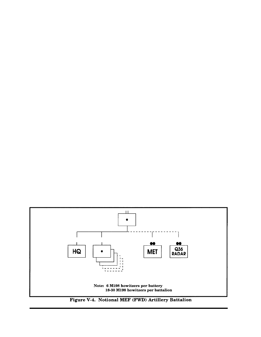
b. MEF (FWD) Fire Support Assets.
(1) Artillery.
The MEF (FWD)
normally deploys with a supporting artillery
battalion comprised of a headquarters
battery, 3 to 5 6-gun M198 howitzer
batteries, and attached meteorological and
radar support. The headquarters battery
includes the battalion headquarters and the
administrative and logistical elements
required to support battalion operations.
Figure V-4 depicts a notional MEF (FWD)
artillery battalion.
(2) Mortars. Each of the MEF’s (FWD)
3 rifle battalions (and the LAR battalion)
features 8 81mm mortars in its organic
weapons company. There are 4 60mm
mortars organic to the weapons platoon of
each rifle company.
c. Naval Surface Fire Support. When
naval fire support is available and the
general tactical situation permits its use,
naval firepower can provide large volumes
of devastating, immediately available, and
responsive fire support to combat forces
operating near coastal waters. Long-range
missiles and carrier-based naval aviation
also enable the JFC to extend reach well
beyond littoral regions to attack targets at
operational depths. The general mission of
naval surface fire support (NSFS) is to
provide fires by Navy surface gun, missile,
and electronic warfare systems in support of
units tasked with achieving the commander’s
objectives.
(1) Naval Gunfire Ships. Naval
gunfire ships may be assigned one of two
missions: direct support (DS) or general
support (GS).
(a) DS. DS makes ship fires
responsive to the needs of a battalion or
regiment size ground force, Destroyers
equipped with 5-inch guns usually execute
this mission. A ship assigned a DS mission
delivers planned and on-call (targets of
opportunity) fires in support of the ground
force. A supporting arms observer, normally
a naval gunfire spotter from the ANGLICO
for the DRB or a member of a shore fire
control party (SFCP) organic to Marine units,
requests and adjusts on-call fires. Note that
naval gunfire direct support does not equate
to artillery direct support. A direct support
ship, for example, responds to calls for fire
from units other than the supported unit
when ordered to do so by the fire support
group commander or by division or brigade
naval gunfire officers.
V-8
(b) GS. Cruisers with 5-inch guns
normally assume general support missions
to provide fires in support of regiment or
larger-size ground forces. Aerial observers
or designated battalion spotters generally
request and control the fires of GS ships.
GS ships also execute planned fires IAW
schedules of fires.
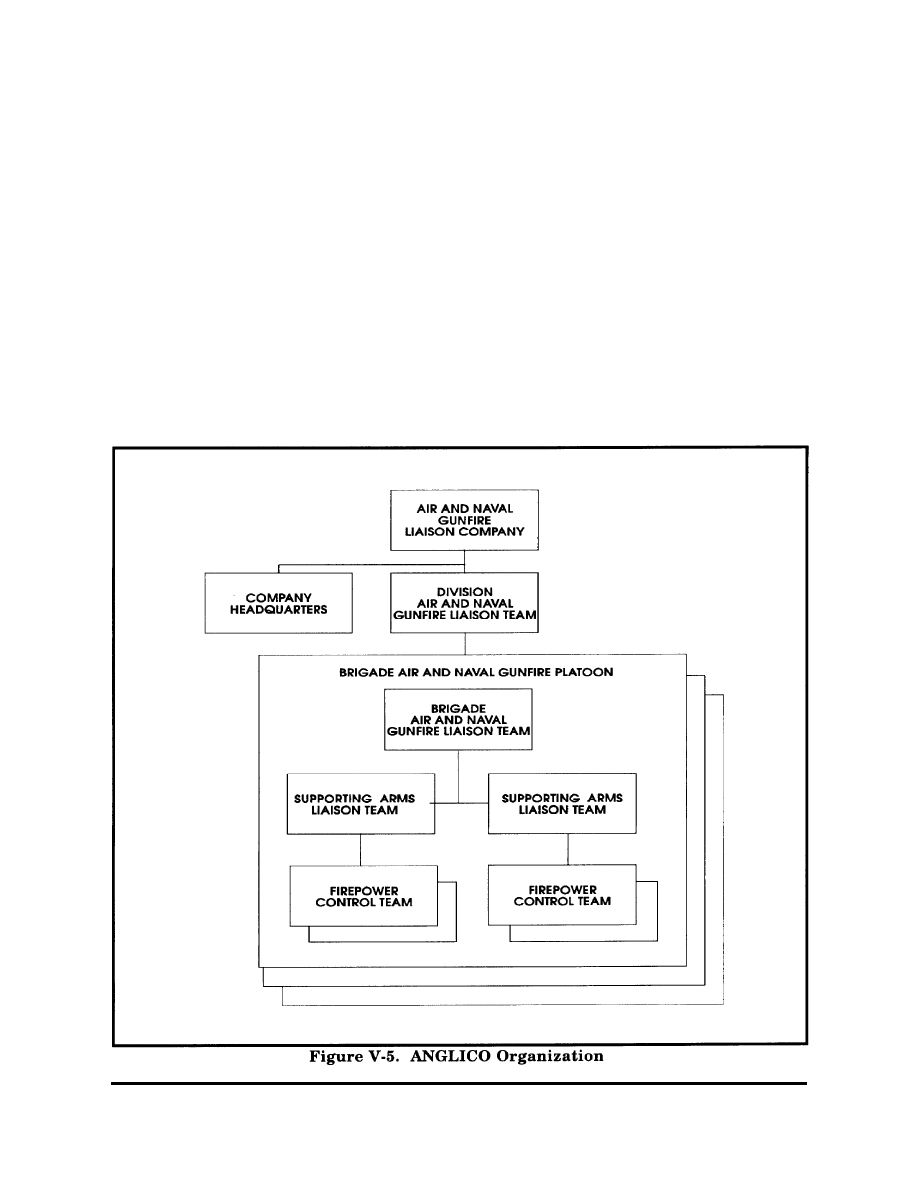
(2) Organization of the ANGLICO.
The ANGLICO is a Marine organization.
In a joint operation, the ANGLICO will
send liaison teams to the other joint
players. The company’s 3 organic brigade
air and naval gunfire platoons are
organized to plan, request, coordinate, and
control naval gunfire and naval air support
for the supported DRB. The DRB receives
support from at least 1 brigade platoon.
Platoons consist of 2 SALTS. Under normal
conditions, these SALTS support 2 of the
maneuver battalions. The SALT consists of
2 SALT officers and 6 enlisted. Two
firepower control teams (FCTs) are
available to support maneuver companies
to request, observe, and adjust naval fire
support. Each FCT has laser designation
capabilities. Figure V-5 portrays the
organization of the ANGLICO.
V-9
d. Marine Aviation. Marine aviation,
operating as part of the concerted air-ground
effort, provides the MEF (FWD) or joint force
commander a significant capability to
destroy, deceive, or disrupt the enemy. The
MEF (FWD) uses the Marine Air Command
and Control System (MACCS) to control
aircraft and missiles.
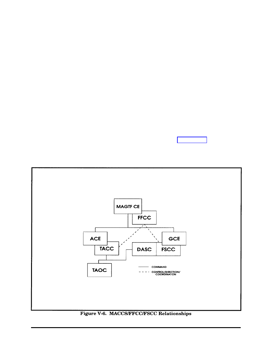
(1) MACCS. The MEF (FWD) FFCC
is linked to the ACE MACCS through the
tactical air command center (TACC).
Paramount to the employment of the MACCS
is the requirement for the MEF (FWD) FFCC
to have connectivity with the ACE TACC and
the GCE FSCCs to be collocated or
electronically connected with a MACCS
agency. Such connectivity promotes the
integration of MEF (FWD) air and ground
assets into a combined arms effort. Figure
(2) Air Tasking Cycle. The MAGTF air
operations tasking process evolves around a
24-hour cycle. The process culminates with
the production and subsequent execution of
the air tasking order (ATO). If the operation
is being conducted under a JFC, the MAGTF
air tasking cycle will conform to the
established joint air tasking cycle procedures.
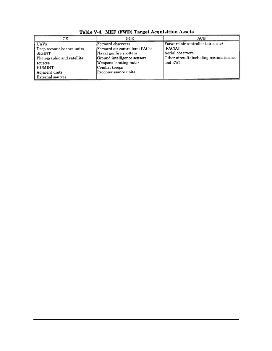
e. MEF (FWD) Target Collection
Assets. The MEF (FWD) CE determines
and coordinates the employment of
information and intelligence collection
assets such as reconnaissance assets,
UAVs, and other target acquisition assets
within the MEF (FWD). To ensure
integration and continuous coverage,
coordination is also made with joint and/or
allied forces.
V-6 depicts MACCS/FFCC/FSCC relationships.
(FWD) target acquisition assets.
V-10
8. Integrated Fire Support Operations
(b) Step 2. On the recommendation
—
——
a. Task Organizing Artillery Assets.
Successful fire support planning and
execution in part hinges on the JFC’s ability
to task organize available fire support assets.
The following highlights the fundamentals
of organizing fire support assets for combat,
describes the process of artillery organization
for combat, and defines the seven inherent
responsibilities in executing artillery tactical
missions.
(1) Fire Support Fundamentals—
(a) Provide adequate fire support
to committed maneuver units.
(b) Weight the main effort.
(c) Provide the commander with
immediately available fire support.
(d) Retain maximum feasible cen-
tralized control.
(e) Provide fire support for future
operations.
(2) Artillery Organization for Combat.
Artillery organization for combat consists of
the 2-step process of establishing command
relationships and assigning tactical missions.
(a) Step 1. The appropriate com-
mander establishes a command relationship
for supporting artillery units of either
attached, OPCON, or TACON.
from the fire support coordinator, the
maneuver commander assigns tactical
missions of direct support, reinforcing,
general support reinforcing, or general
support to artillery units.
• DS. DS is the most decentralized
tactical mission wherein an artillery unit
provides close and continuous fire support
to a specific maneuver unit.
• Reinforcing (R). An artillery unit
with a reinforcing mission augments the
fires of another artillery unit with a DS
mission. This mission weights an effort and
provides additional responsive fires to the
supported maneuver commander. An
artillery unit can reinforce only one other
artillery unit at a time.
• GSR. An artillery unit with a
GSR mission furnishes fires for the entire
force within its range and reinforces the
fires of another artillery unit as a second
priority.
• GS. GS, the most centralized
mission, retains artillery to support the
force as a whole and provides the
commander with immediately available
firepower to influence the battle.
(3) Inherent Responsibilities. Table
V - 5 d e s c r i b e s t h e s e v e n i n h e r e n t
responsibilities of field artillery tactical
missions that guide the planning and
operational employment of artillery assets
during integrated operations.
V-11
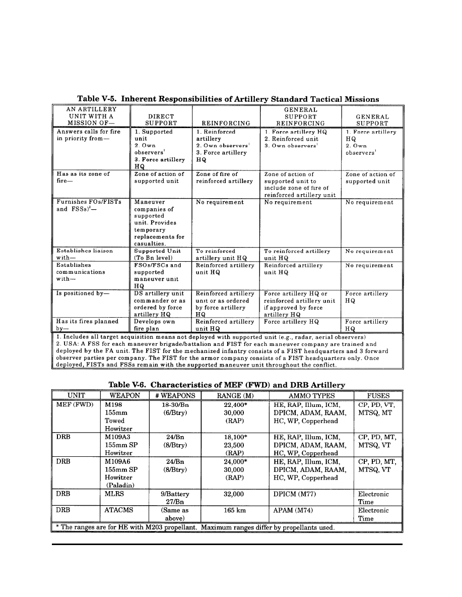
b. Characteristics of MEF (FWD) and
DRB Artillery.
Table V-6 provides
commanders and staffs with a ready
reference that delineates the characteristics
of artillery weapons systems available to the
MEF (FWD) and DRB.
V-12

c. Counterfire Operations.
Given the vulnerability of our forces—
particularly our “light” combat forces and our
combat and combat service support units—
to enemy artillery, the JFC and subordinate
commanders and staffs must devote special
attention to providing effective counterfire
against an artillery-rich foe. The USMC does
not have organic MLRS or Q-37 radar to
assist in providing counterfire; Marine
commanders rely primarily on organic
artillery units, Marine aviation, and
attached/OPCON MLRS provided by the
Army for counterfire. The most effective
counterfire system will often be the MLRS.
To maximize the capabilities of the MLRS
battery, direct “sensor-to-shooter” linkage
may be established from specific sensors to
the MLRS battery. Linking the battery with
a Q-36 or (preferably) a Q-37 provides the
commander with a responsive counterfire
capability to locate and attack firing enemy
indirect fire systems. When the MEF (FWD)
must rely on Marine aviation for long-range
counterfire, “sensor-to-shooter” linkage can be
established with a quick-fire channel
connecting an air officer in the target
processing center directly to a TAC(A). A
proactive counterfire strategy links sensors
(such as a USMC UAV) with the MLRS or
other attack means in order to locate, attack,
and eliminate enemy artillery before it enters
the fight.
d. MLRS Support of USMC Operations.
Task organizing the MEF or MEF (FWD)
with supporting MLRS units provides
respective commanders with a significantly
enhanced indirect fire capability to conduct
counterfire operations. The discussion below
addresses command and control of MLRS
units under MEF control, describes required
communications linkages, and highlights
planning
considerations
for MLRS
employment.
(1) Command and Control. The MEF
commander may elect to employ attached
MLRS unit(s) in general support of the MEF
or assign other tactical missions to support
MEF ground units. When operating under
USMC control, MLRS units should be placed
within the artillery organization but could
be tasked to support the MEF (FWD) as a
whole. The senior artillery headquarters
establishes the tactical mission of the MLRS
unit by assigning it a GS mission or
nonstandard GSR or R missions. The senior
fire direction center exercises tactical fire
control over attached MLRS units; the senior
artillery commander or S3 directs the
positioning of GS and GSR MLRS units and
associated radars under regimental control
of the artillery headquarters.
(2) Communications. The MLRS unit
operates on the following external nets when
supporting USMC operations:
(a) Regimental Command Net (HF).
(b) Regimental Tactical Net (VHF).
(c) Regimental Fire Direction
Net (VHF).
(d) Radar Telling Net (VHF), as
required.
(e) Regimental Survey/Met Net
(VHF), as required.
(f) Regimental Communication
Coordination Net (HF/VHF).
(3) Employment Considerations. The
employment of the MLRS unit will be similar
to the employment of a Marine artillery
battalion with a GS mission. MLRS
operations are characterized by rapid
emplacement, engagement, and displace-
ment of widely dispersed launchers. Specific
planning considerations include—
(a) Sustained Operations/Launcher
Response Time. Schedules of fire must be
coordinated so the battery can manage
launcher posture and/or response time.
Because of maintenance, personnel, and
other factors, “rule of thumb” is to plan fires
for no more than 6 launchers at one time. If
V-13

a surge condition arises, the unit can be
tasked to provide a higher number. If all
available launchers fire on a schedule,
temporary loss of the asset (20 to 45 minutes)
can be expected while the launchers move to
reload points, reload, and return to firing
points.
• Launcher Response Posture.
On the basis of METT-T, the force com-
mander’s guidance, ammunition resupply,
and launcher maintenance status, the
commander determines how unit launchers
are postured. A launcher response posture
is its readiness to respond to fire missions.
The terms hot, cool, and cold indicate
launcher response posture.
• • Hot status indicates the
launcher is fully capable of firing. Status is
based on the launcher’s electrical and
mechanical systems, not on its location or
ammunition load.
• • Cool status indicates a
launcher is capable of firing but only after a
warm-up period of about 8 minutes.
• • Cold status indicates the
launcher is not mission-capable for
maintenance reasons or that one or more
essential systems are shut down for
maintenance, preventive maintenance
checks and services (PMCS), crew rest, and
so forth. If a cold launcher is mission-capable,
it may take 30 minutes or more for it to
respond.
• Tactical Posturing. The battery
directs the platoons to maintain a specific
number of launchers in a hot status. This is
based on guidance from the controlling FA
headquarters, METT-T, total launchers
available, ammunition available, crew rest,
and fatigue. The platoons usually rotate their
launchers through hot status, changing
individual launchers and maintaining the
total number of required hot launchers.
(b) Fire Planning. The MLRS uses
two basic types of fire missions in support of
close operations: planned (scheduled) and
targets of opportunity (unscheduled). Given
the different platoon positions described
above, at least 30 minutes may be required
for the entire MLRS battery to execute a fire
plan. In scheduling MLRS fires, each
launcher is given a separate line on the
scheduling worksheet.
(c) Positioning. MLRS fights as
close to the FLOT as possible in order to
maximize its 32 km range and offset the
range advantage enjoyed by some enemy
indirect fire systems. METT-T availability of
ground maneuver units to protect MLRS, the
scheme of maneuver, and a degree of risk
acceptable to the commander dictate
employment and positioning decisions.
(d) Increased Target Processing
Requirements. Because of the additional
target production from radars accompanying
attached MLRS, the Marine target
processing center may require augmentation
by target processing sections to efficiently
process targets.
(e) Ammunition Expenditure.
MLRS ammunition consumption requires
intense management by planners, operations
personnel, and logisticians. Requirements for
current and projected operations are
balanced against the controlled supply rate;
MLRS support and appropriate controls are
established accordingly. The missile profile,
the measure of effort expected of a system
under various levels of combat intensity,
provides one methodology of determining the
anticipated consumption rates for MLRS
units (see Table V-7). These levels of
intensity include—
• Supported level of effort
expended per day over an extended period of
combat for a committed force; it is normally
expected to occur 75 percent of the time for
MLRS units.
• Surge level of effort required
when a committed force faces a main attack;
it is expected to occur less than 20 percent of
the time for MLRS units.
V-14
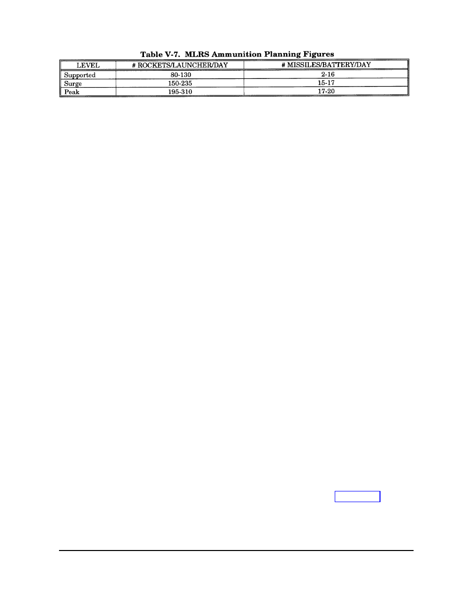
• Peak level of effort during an
intense period of combat. Direct support and/
or reinforcing artillery within a selected
brigade area are likely candidates; it is
expected less than 5 percent of the time for
MLRS units.
(f) Maintenance Support. MLRS
units attached to the MEF must deploy with
the appropriate automotive and missile
maintenance personnel, equipment, and
repair parts required to conduct sustained
combat operations. The MEF possesses no
capability to support specialized MLRS
equipment.
(g) Troop Safety. Troop safety
considerations normally preclude employ-
ment of MLRS in proximity to friendly
personnel. Danger close for MLRS M26
rockets is 2 km at maximum range. For
planning purposes, MLRS fires are generally
directed no closer than 2 km beyond the
FLOT. The potential for unexploded
ordnance (UXO) in areas where large
volumes of MLRS fires have occurred must
be considered from both troop safety and
maneuver/movernent standpoints during
operational planning and execution.
e. Close Air Support (CAS) Operations.
(1) CAS for the DRB when deployed
with the MEF. Army forces normally receive
CAS from the Air Force and are provided
with Air Force liaison parties that request,
coordinate, and control available Air Force
CAS. The key consideration for providing
Marine or Navy CAS to the DRB is sufficient
numbers of terminal controllers from the
MAGTF.
(a) ANGLICO Support. Terminal
controllers normally come from ANGLICO in
the form of FCTs that are trained and
equipped to provide planning advice and CAS
terminal control for Marine aviation. Likely
j
the DRB will receive an ANGLICO brigade
liaison platoon consisting of a BLT, 2 SALTS,
and 4 FCTs. The BLT acts as the principal
staff coordinator for Navy and Marine Corps
CAS and naval gunfire for the DRB
commander. SALTS operate at the battalion/
task force level and each has 2 FCTs that
support committed companies. The SALT
officer in charge (OIC) (either a naval aviator
or flight officer) plans, requests, coordinates,
and (when required) controls Navy and
Marine Corps CAS or NSFS for DRB task
forces. The FCT, comprised of 1 officer (a
universal spotter) and 5 enlisted Marines,
plans and controls CAS and NSFs for the
forward companies of a task force.
(b) CAS Request Flow, SALTS
submit requests for preplanned Navy and
Marine CAS through fire support
coordination agencies in the maneuver chain
of command, first to the BLT at the DRB
FSE, next to the division FSCC for
consolidation, then to the MEF FFCC for
approval, and ultimately to the ACE via the
Marine TACC for planning and execution if
approved by the MEF. Requests for
immediate Navy and Marine Corps CAS are
submitted by the FCT to the DASC on the
tactical air request (TAR) Net (HF). The
SALT monitors this net and provides any
coordination necessary at that level.
Terminal control of CAS aircraft supporting
the DRB is normally provided by ANGLICO
FCTs. In the absence of an observer, Marine
air may be controlled by the company FSO,
ALO, or Air Force FAC. Chapter VII provides
additional detail on CAS request procedures.
(c) Considerations. Although the
brigade liaison platoon normally consists of
V-15

2 SALT teams, Desert Storm after action
reports recognized the need for 3 SALTs per
brigade team
rather than 2. DRB
commanders must also consider the force
protection issue when receiving supporting
ANGLICOs; SALTs are equipped with
HMMWVs and do not enjoy the protection
afforded by the Abrams tank and Bradley
fighting vehicle.
(2) CAS for the MEF (FWD) When
Deployed with a Corps. The MEF (FWD)
possesses CAS-capable aircraft and the
means to coordinate and control those
aircraft. Except in exceptional circumstances,
Marine aviation remains under the OPCON
of the MAGTF commander. Chapter VII
addresses procedures for requesting air
support when the MEF (FWD) requires
support that exceeds the capability of the
MEF (FWD) ACE.
f. Naval Surface Fire Support of the DRB.
(1) Procedures during Amphibious
Assaults. During amphibious phases of a
joint operation, a naval task force provides
interface with the DRB FSE through the
ship-based supporting arms coordination
center (SACC). The SACC is responsible for
coordinating all fires during the assault. To
facilitate the coordination of fires in support
of the landing force assault to shore, the
SACC augments with personnel and
equipment from the MAGTF FFCC and the
senior GCE FSCC. Normal coordination is
through the Artillery Command Fire (CF) or
Fire Direction (FD) Nets. The Landing Force
Fire Support Coordination Net (HF) can
serve as a backup. To minimize dependence
on ship-to-shore communications and
because higher echelons may not be ashore,
units conduct lateral coordination when fires
clearance must be obtained from only one
other landing force unit. When ashore and
prepared, the FFCC assumes responsibility
for fire support coordination from the SACC.
The change in responsibility depends on
which agency possesses the best capability
to coordinate and is contingent on the
commander, amphibious task force (CATF)
decision.
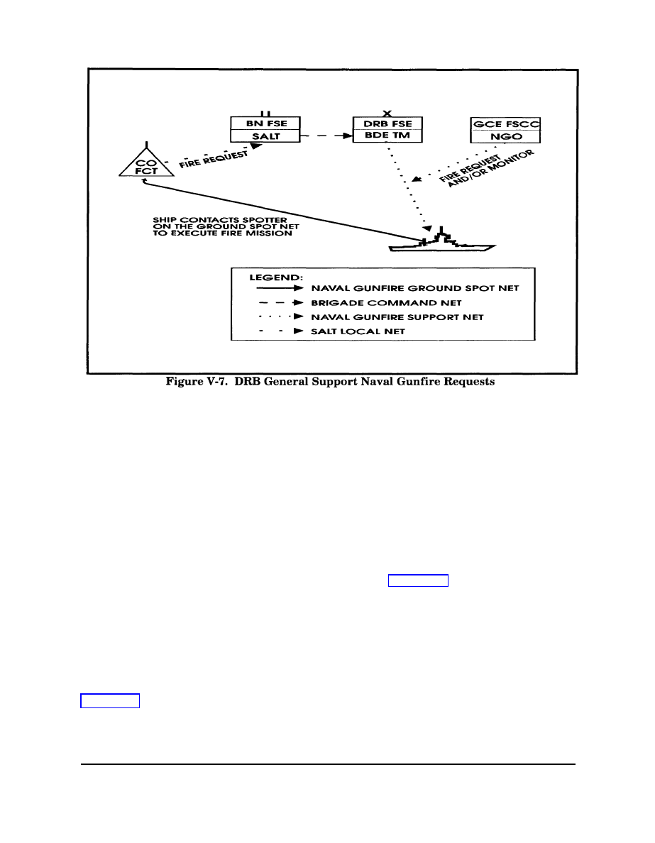
(2) Procedures Ashore. The BLT
maintains communications on the NGF
Support and/or NGF Control Net (HF) and
the Brigade Command I and II Nets (VHF).
These nets provide communications for the
planning and coordination of NSFS between
the NSGS ships, the GCE FSCC, the BLT,
and SALTs. These nets support day-to-day
planning among these agencies. The SALTs
and FCTs maintain communications on the
SALT Local (VHF) and NGF Ground Spot
(HF) Nets. The SALT at the battalion FSE
monitors any requests for NSFs on the NGF
Ground Spot Net and coordinates as
necessary with the BLT. Figure V-7
illustrates general support naval gunfire
requests at the DRB level.
Army personnel also request and conduct
fire support missions using naval gunfire in
the absence of ANGLICO personnel. The
naval gunfire communications interface
includes a designated naval gunfire ground
spot net with a frequency of 2-30 MHz HF.
Compatible communications equipment
includes: USMC—PRC-104, GRC-193, MRC-
138; USA—GRC-106, GRC-193, and Single-
channel Ground and Airborne System
(SINCGARS) family of radios; USAF—PRC-
104, MRC-107/108, GRC-206.
g. Naval Air Support of the DRB. Navy
aircraft provide support to the DRB when
available. The primary missions of Navy
aircraft are fleet air defense and offensive
attack. When designated to support the DRB,
Navy aircraft are placed in a general aircraft
sortie pool for tasking by the Navy TACC.
Communications and control of Navy aircraft
are the same as for Air Force aircraft. Air
interdiction (AI) sorties are tasked by the
Navy TACC. CAS sorties require the same
positive control as Air Force CAS during the
actual strike. As with Air Force CAS, the Air
Force FAC, ANGLICO, or Army FIST
provide the required control. The DRB must
be operating in an AOA or receiving its
V-16
primary tactical air support from the Navy.
In this case, the naval air commander would
likely be the air component commander. An
Army battlefield coordination element (BCE)
may be required to deploy to the CATF’s
TACC to perform the full functional interface
and coordination as it does with the Air Force
air operations center (AOC).
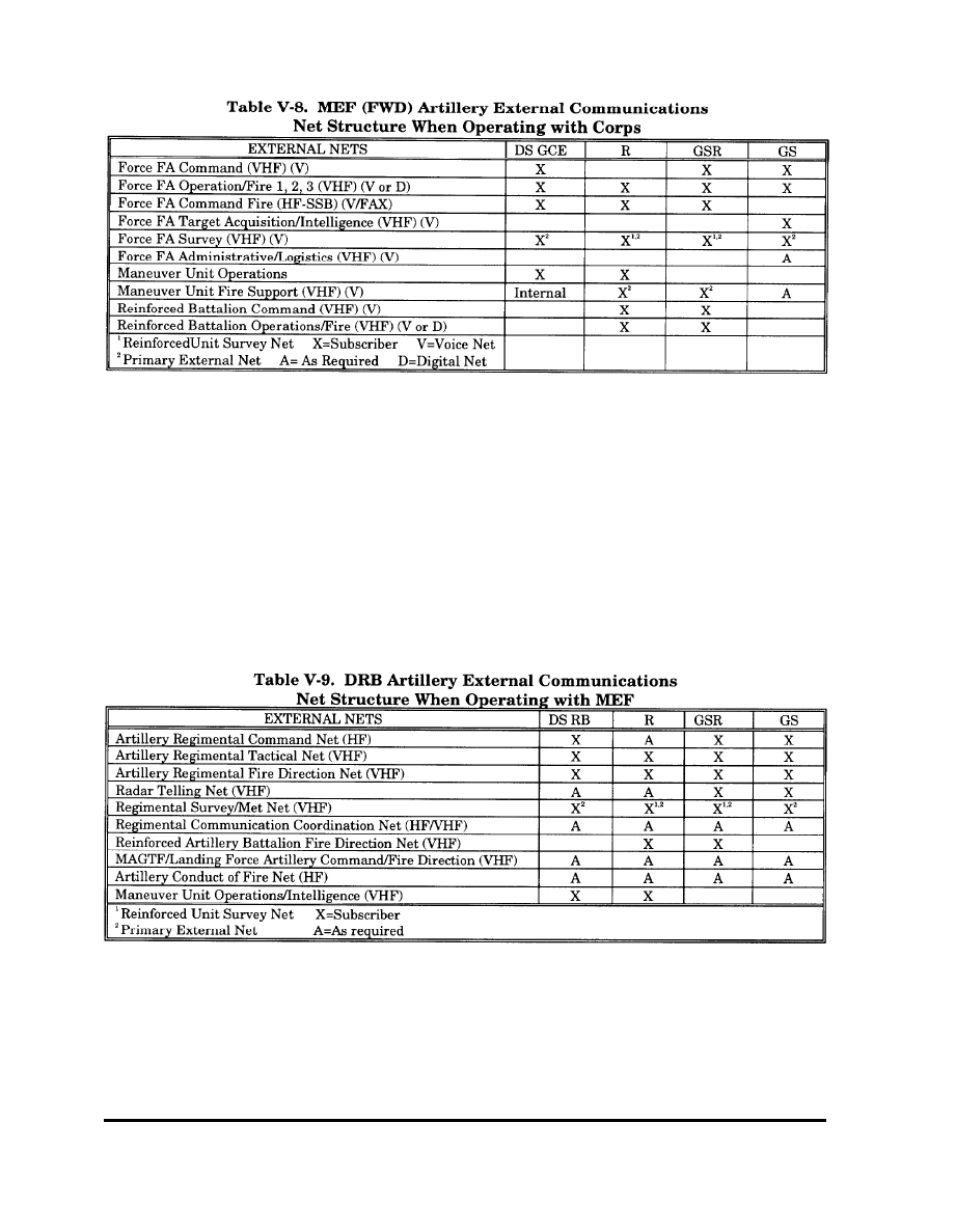
h. Artillery
Communications. The
artillery unit’s ability to communicate is
arguably the greatest single factor in
determining whether or not the unit will
accomplish its mission. The discussion below
defines the external operating nets for the
artillery battalions supporting the MEF
(FWD) when operating with a corps and for
the DRB when operating with a MEF
respectively:
(1) MEF (FWD) Under Corps Control.
Table V-8 identifies the external nets that
the MEF’s (FWD) supporting M 198 artillery
battalion must operate in when the MEF
(FWD) fights as part of a corps. The table
assumes the artillery battalion performs a
tactical mission of direct support for the
MEF’s (FWD) GCE. However, there may be
occasions (e. g., when the MEF [FWD] is
assigned a reserve mission) when the
assignment of reinforcing, general support
reinforcing, or general support missions may
be appropriate.
(2) MEF (FWD) under MEF (FWD)
Control. Table V-9 identifies the external
nets the DRB’s supporting artillery battalion
must operate in when the DRB fights as part
of a MEF (assuming artillery regimental
headquarters is present). The table presumes
the artillery battalion will only perform a
tactical mission of direct support for the DRB.
However, there may be occasions (e.g., when
the DRB is assigned a reserve mission) when
the assignment of reinforcing, general
support reinforcing, or general support
missions may be appropriate.
V-17
V-18
Wyszukiwarka
Podobne podstrony:
Ch5 pg155 220
Ch5 Q1
Ch5 Layers & Layer Groups
cisco2 ch5 concept SHZWZYJFASP4NH42Z32ORE227DP7NOQMEKX3KEA
Ch5 Q3
Ch5 E3
Ch5 E8
4 ch5
Ch5
Ch5 E5
ch5 pl
Ch5 4 EnvironmentalSustainabilityOfForestEnergyProduction
Ch5 E7
ch5 pl p3
ch5
ch5
cisco2 ch5 focus HM6IBS7SIWLTS7OQGINJHJ365QI5N3JGW4XK5WA
Ch5 5 EnvironmentalSustainabilityOfForestEnergyProduction
CH5
więcej podobnych podstron