
USER INTERFACE
SERVICE TECHNICIAN
S30FT, S35FT, S40FTS [E010];
H1.6FT, H1.8FT, H2.0FTS
(H30FT, H35FT, H40FTS) [F001];
S2.0-3.5FT (S40-70FT, S55FTS ) [F187];
H2.0-3.5FT (H40-70FT) [L177]
This manual contains information that is confidential and/or proprietary to Hyster
Company, its subsidiaries and/or vendors. Copying or distribution of any sections of
this manual marked "Confidential/Proprietary" is prohibited.
PART NO. 1580519
2200 SRM 1131

SAFETY PRECAUTIONS
MAINTENANCE AND REPAIR
• When lifting parts or assemblies, make sure all slings, chains, or cables are correctly
fastened, and that the load being lifted is balanced. Make sure the crane, cables, and
chains have the capacity to support the weight of the load.
• Do not lift heavy parts by hand, use a lifting mechanism.
• Wear safety glasses.
• DISCONNECT THE BATTERY CONNECTOR before doing any maintenance or repair
on electric lift trucks. Disconnect the battery ground cable on internal combustion lift
trucks.
• Always use correct blocks to prevent the unit from rolling or falling. See HOW TO PUT
THE LIFT TRUCK ON BLOCKS in the Operating Manual or the Periodic Mainte-
nance section.
• Keep the unit clean and the working area clean and orderly.
• Use the correct tools for the job.
• Keep the tools clean and in good condition.
• Always use HYSTER APPROVED parts when making repairs. Replacement parts
must meet or exceed the specifications of the original equipment manufacturer.
• Make sure all nuts, bolts, snap rings, and other fastening devices are removed before
using force to remove parts.
• Always fasten a DO NOT OPERATE tag to the controls of the unit when making repairs,
or if the unit needs repairs.
• Be sure to follow the WARNING and CAUTION notes in the instructions.
• Gasoline, Liquid Petroleum Gas (LPG), Compressed Natural Gas (CNG), and Diesel fuel
are flammable. Be sure to follow the necessary safety precautions when handling these
fuels and when working on these fuel systems.
• Batteries generate flammable gas when they are being charged. Keep fire and sparks
away from the area. Make sure the area is well ventilated.
NOTE: The following symbols and words indicate safety information in this
manual:
WARNING
Indicates a condition that can cause immediate death or injury!
CAUTION
Indicates a condition that can cause property damage!

User Interface
Table of Contents
TABLE OF CONTENTS
General ...............................................................................................................................................................
Description .....................................................................................................................................................
Dash Display Menu Access ...........................................................................................................................
Menu Navigation ...............................................................................................................................................
Main Menu .........................................................................................................................................................
Passwords ...........................................................................................................................................................
Adding Passwords..........................................................................................................................................
Hourmeters ........................................................................................................................................................
View Versions .....................................................................................................................................................
VSM Versions.................................................................................................................................................
Dash Display Versions...................................................................................................................................
Engine Controller Version.............................................................................................................................
Transmission Controller Version ..................................................................................................................
Truck Serial Number .....................................................................................................................................
Truck Configuration ......................................................................................................................................
Diagnostics .........................................................................................................................................................
Clear Fault Log..............................................................................................................................................
View Fault Log...............................................................................................................................................
No-Run Data Display ....................................................................................................................................
Engine Accelerator and Throttle Data Display............................................................................................
Engine Speeds and Governor Data Display .................................................................................................
Engine Fuel and Emissions Data Display....................................................................................................
Engine General Data Display .......................................................................................................................
XMSN/Brake Data Display ...........................................................................................................................
Hydraulic Data Display.................................................................................................................................
General Truck Data Display .........................................................................................................................
Set Travel and Braking......................................................................................................................................
Speed Limit ....................................................................................................................................................
Acceleration Rate...........................................................................................................................................
Auto-Deceleration Rate .................................................................................................................................
Set Power Reversal Rate ...............................................................................................................................
Set Inching/Brake Overlap............................................................................................................................
Setup Hydraulics ...............................................................................................................................................
Lift Maximum Speed .....................................................................................................................................
Lower Maximum Speed.................................................................................................................................
Tilt Maximum Speed .....................................................................................................................................
Auxiliary Function One, Direction A, Maximum Speed..............................................................................
Auxiliary Function One, Direction B, Maximum Speed..............................................................................
Auxiliary Function Two, Direction A, Maximum Speed..............................................................................
Auxiliary Function Two, Direction B, Maximum Speed..............................................................................
Auxiliary Function Three, Direction A, Maximum Speed...........................................................................
Auxiliary Function Three, Direction B, Maximum Speed...........................................................................
Lift/Lower Ramp Rate ...................................................................................................................................
Hydraulic Auxiliary Ramp Rate ...................................................................................................................
Return to Set Tilt Delay/On/Off ....................................................................................................................
Setup Display .....................................................................................................................................................
Set Service Language ....................................................................................................................................
Setup General Items ..........................................................................................................................................
Motion Alarm Activation Type......................................................................................................................
Light Shutdown Time-Out ............................................................................................................................
Restore Default Settings ...............................................................................................................................
©2005 HYSTER COMPANY
i

Table of Contents
User Interface
TABLE OF CONTENTS (Continued)
Restore Engine Controller Default Calibration ...........................................................................................
Calibrations........................................................................................................................................................
Calibrate Transmission Valve .......................................................................................................................
Set Tilt Stop Point .........................................................................................................................................
Calibrate Travel Speed Sensor......................................................................................................................
This section is for the following models:
S30FT, S35FT, S40FTS [E010];
H1.6FT, H1.8FT, H2.0FTS (H30FT, H35FT, H40FTS) [F001];
S2.0-3.5FT (S40-70FT, S55FTS ) [F187];
H2.0-3.5FT (H40-70FT) [L177]
ii
2200 SRM 1131
General
General
DESCRIPTION
This section contains information on accessing the
additional service technician functions of the dash
display. With a proper service technician password,
the service technician can access menu items not vis-
ible to persons with operator or supervisor password
level access.
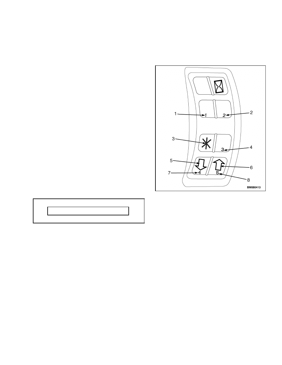
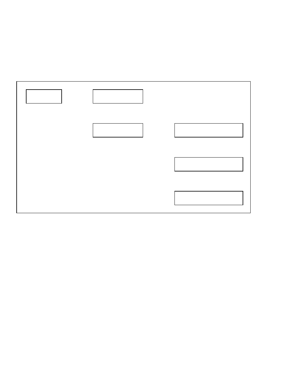
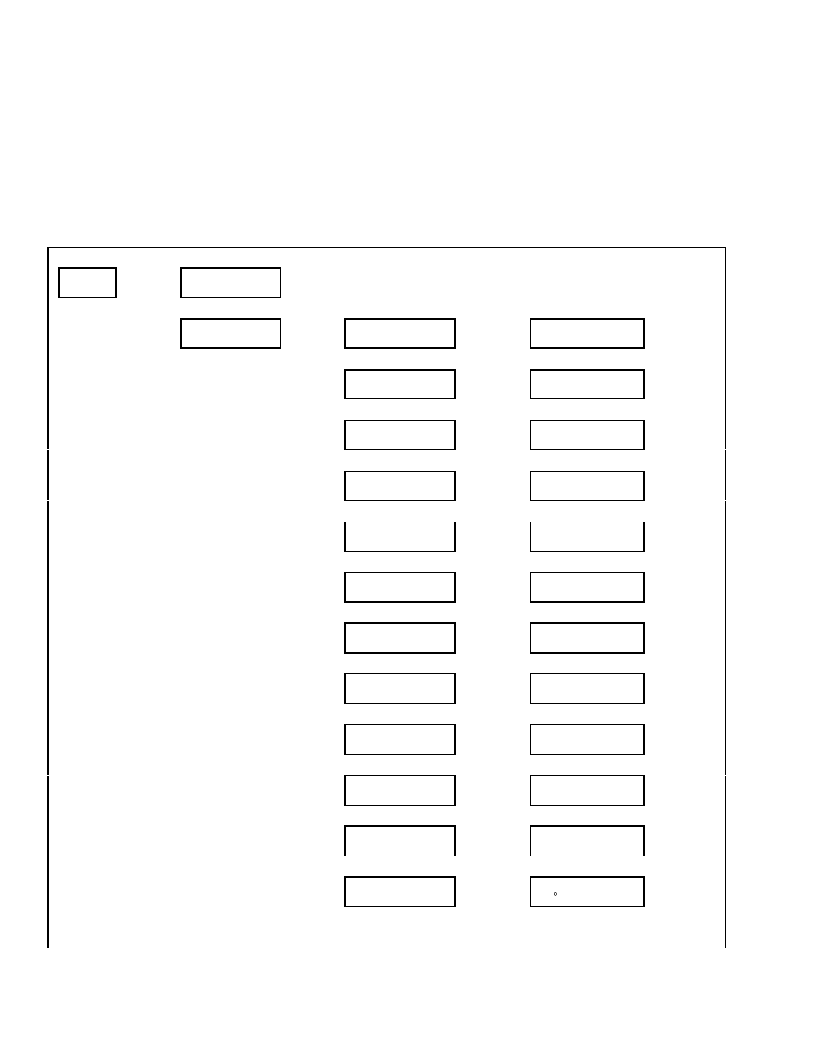
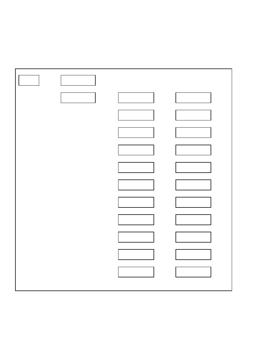
DASH DISPLAY MENU ACCESS
When the key is turned to the ON position or the
Power On button is pushed, the menu access keys
will be activated. See Figure 1.
If the operator passwords function is activated, the
password screen will be shown at startup. See Ta-
ble 1. Enter your five-digit service technician pass-
word using the five number keys on the right-hand
dash display input panel. See Passwords in this sec-
tion. After input of your service password, the screen
will automatically revert to the Main Menu, Pass-
words screen. Use the scroll keys #4 and #5 to scroll
through the main menu. This will enable all dash
display menu options allowed for service technician
password access.
Table 1. Password Screen
Enter Password XXXXX
If the operator passwords function is not activated or
a non-service technician password has been entered
at the initial passwords screen on the dash display,
the passwords entry screen may be accessed by press-
ing the
*
key to enter the Main Menu and selecting
Passwords.
1.
NUMERICAL PASSWORD ENTRY KEY #1
2.
NUMERICAL PASSWORD ENTRY KEY #2
3.
ENTER KEY
4.
NUMERICAL PASSWORD ENTRY KEY #3
5.
SCROLL DOWN KEY
6.
SCROLL UP KEY
7.
NUMERICAL PASSWORD ENTRY KEY #4
8.
NUMERICAL PASSWORD ENTRY KEY #5
Figure 1. Menu Access Keys
Confidential/Proprietary - Do Not Copy or Duplicate
1

Main Menu
2200 SRM 1131
Menu Navigation
Upon successful entry of your service technician
password, you will be directed to the Main Menu.
Using the scroll keys #4 and #5, scroll through the
menu selections until you see the menu selection
you want to access. Press the
*
key to access that
selection.
The
*
key allows you to move from menu to menu
and is used to make selections within a menu. The
#4 and #5 scroll keys allow you to move up and down
within a menu.
Each menu (except the Main Menu) will have a Back
1 Level option within the menu options at that level.
Use the scroll keys #4 and #5 to access this option.
Press the
*
key to select this option and return to
the previous menu.
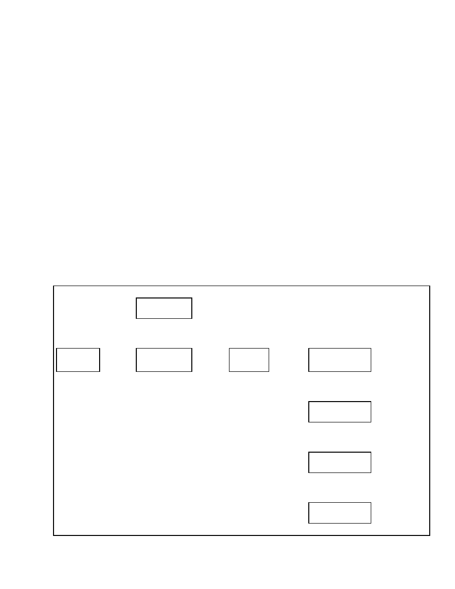
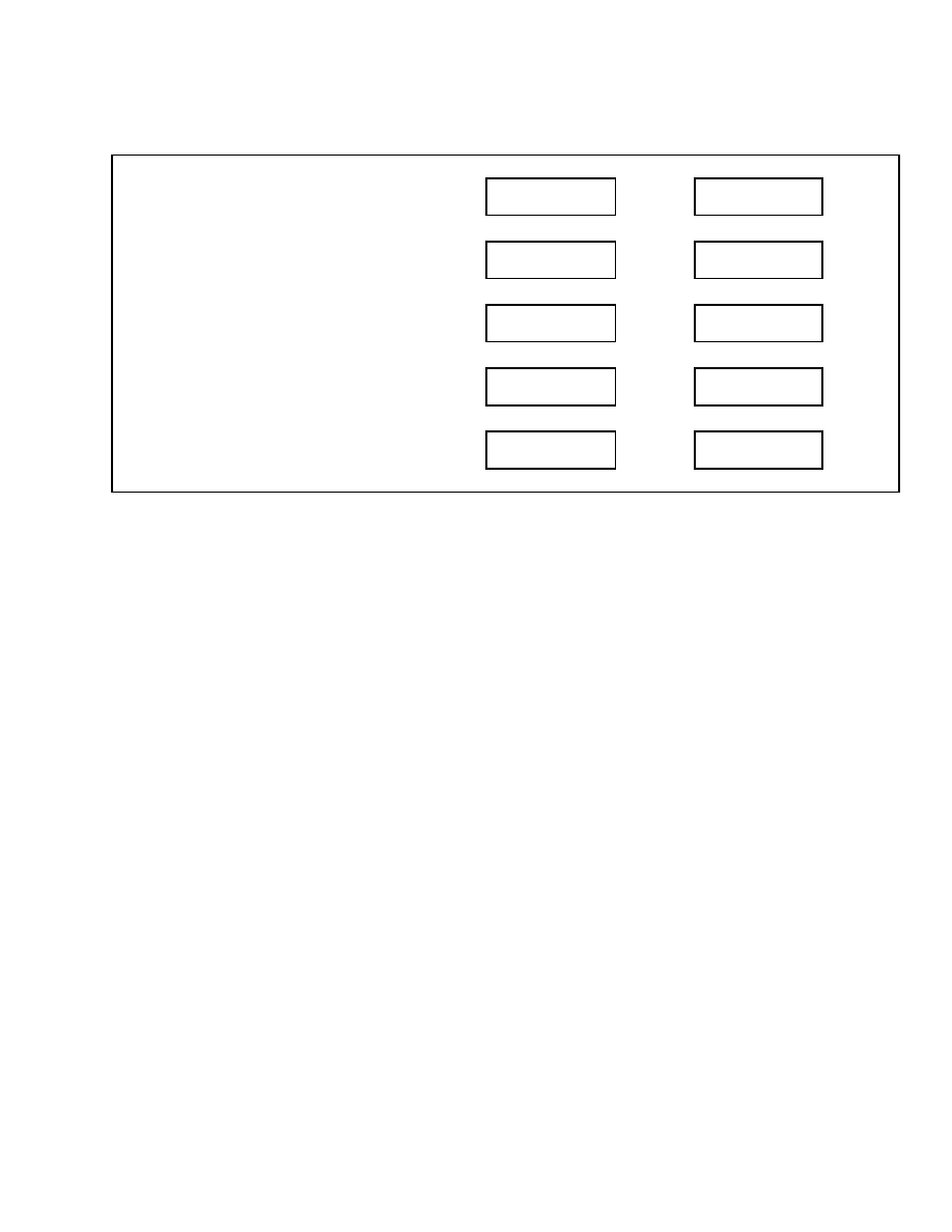
Any time an optional value is changed within a
menu, pressing the
*
key will take you to the Exit
Menu where you will have the opportunity to return
to the previous menu, exit the menu system without
saving any changes, or save your changes and exit
the menu system. See Table 2.
Some menus may contain several optional values
that can be adjusted. It is not necessary to exit the
menu after each adjustment and re-enter the menu
to make multiple changes within a menu.
After
making a change to an optional value, use the Back
1 Level option to re-enter the menu, scroll to the
next option to be adjusted, and make the change.
After all adjustments have been made, press the
*
key to access the Exit Menu and save your changes.
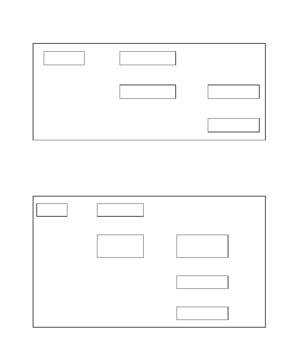
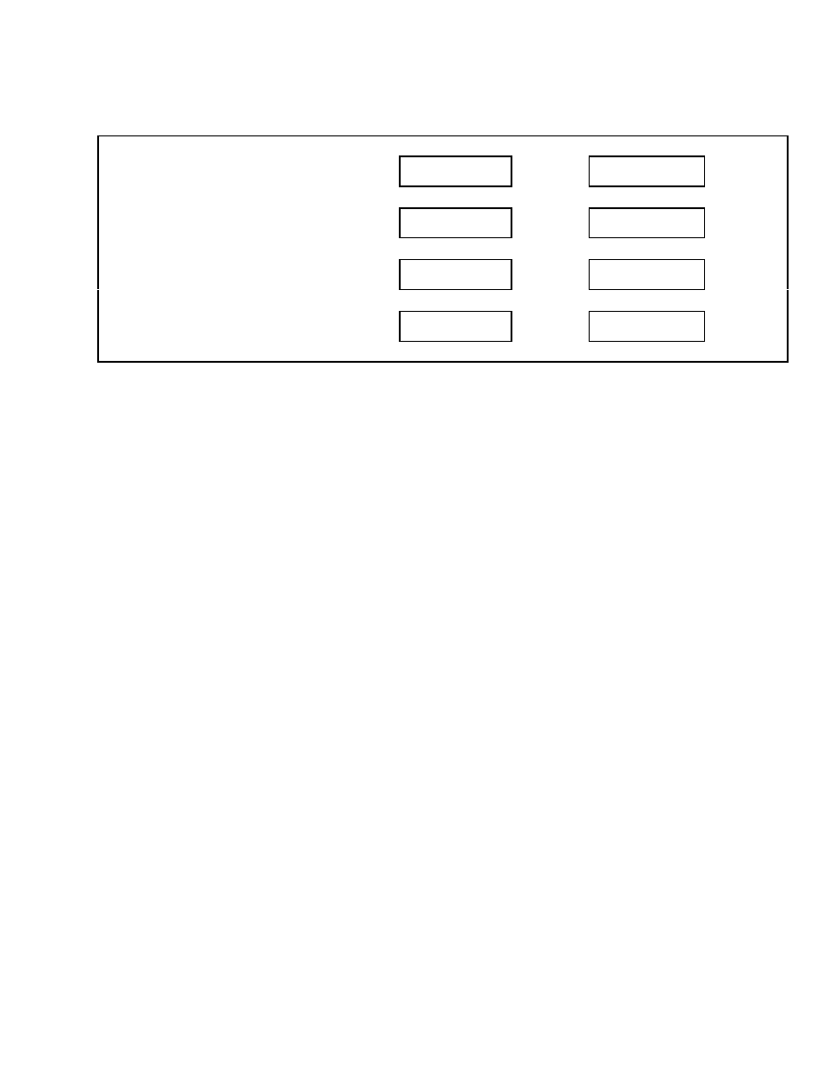
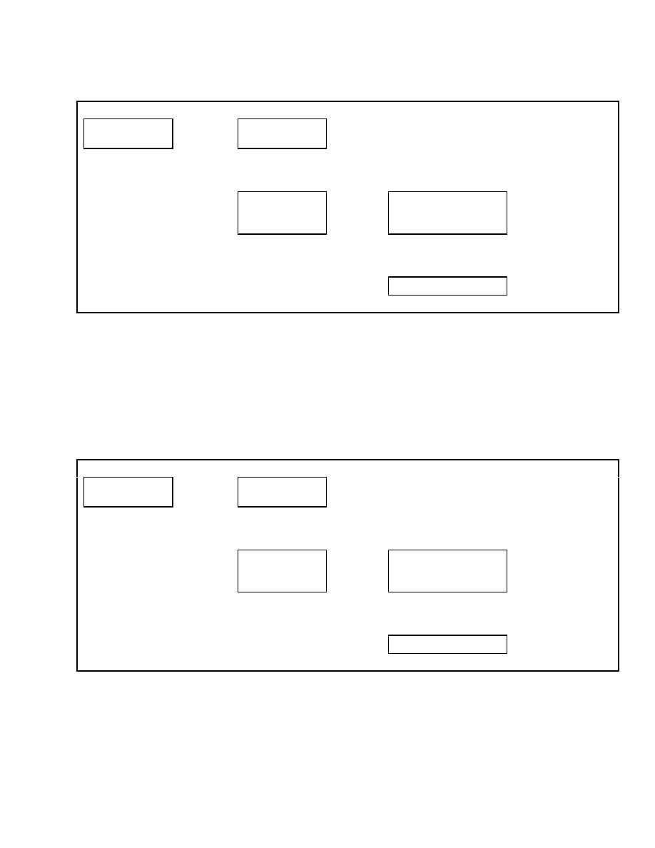
Table 2. Exit Menu
Main Menu
Save and Exit
Press
*
Key
Save All Changes
and Exit Menu - Yes
Press
*
Key to Save
Changes
↑
SCROLL
↓
↑
SCROLL
↓
Main Menu
Exit Without Saving
Cancel Save
Return to Menu
Press
*
Key to Exit and
Return to Menu
Main Menu
NOTE: Depending upon how the lift truck is
equipped, some of the functions described in this
section may not be included in the on-board menu
structure for a particular lift truck.
Upon entering the Main Menu from the password en-
try screen, the following menu functions are visible
to the service technician:
• Hourmeters
• View Versions
• Passwords
• Diagnostics
• Set Travel and Braking
• Setup Hydraulics
• Setup Display
• Setup General Items
• Calibrations
• Save and Exit
• Exit Without Saving
2
Confidential/Proprietary - Do Not Copy or Duplicate
2200 SRM 1131
Passwords
Passwords
Service level password access is required to add,
delete, or edit Service Level Passwords and the first
installation of a Supervisor level password. Anyone
with Service Level access can add, delete, or edit
Operator or Supervisor passwords using the Dash
Display or PC Service tool.
The default Service Level password installed at the
factory is 55555. Use this password when installing
the lift truck at the customer location to set up cus-
tomer passwords in the display. When initial instal-
lation is complete, choose a new personal password
and enter it into the dash display. When you have
entered your personal service technician password in
the dash display, the default password can no longer
be used to access the service technician function of
the dash display. If a Service Technician password is
lost, the password can be reset using the PC Service
Tool.
Once activated, the service technician password will
remain active until the key is turned to the OFF
position and the Password Time-Out function cycles
through the Time Delay setting. The service techni-
cian password can also be immediately disabled after
completing the lift truck service by turning the key to
the OFF position and then pressing the
*
key three
times
*
,
*
,
*
.
NOTE: The Service Technician must install the first
Supervisor password into the dash display. Once an
initial Supervisor password is installed, then that
password access can add additional Supervisor pass-
words to the dash display.
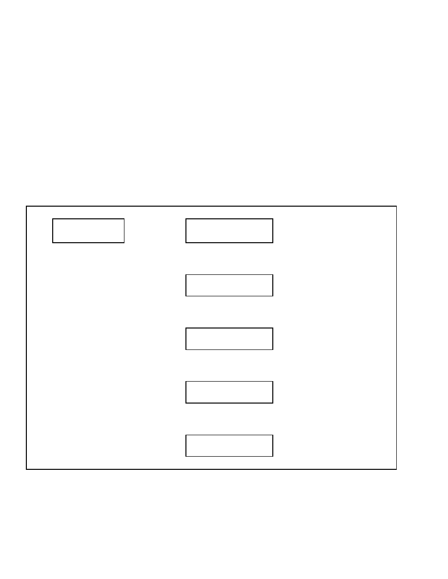
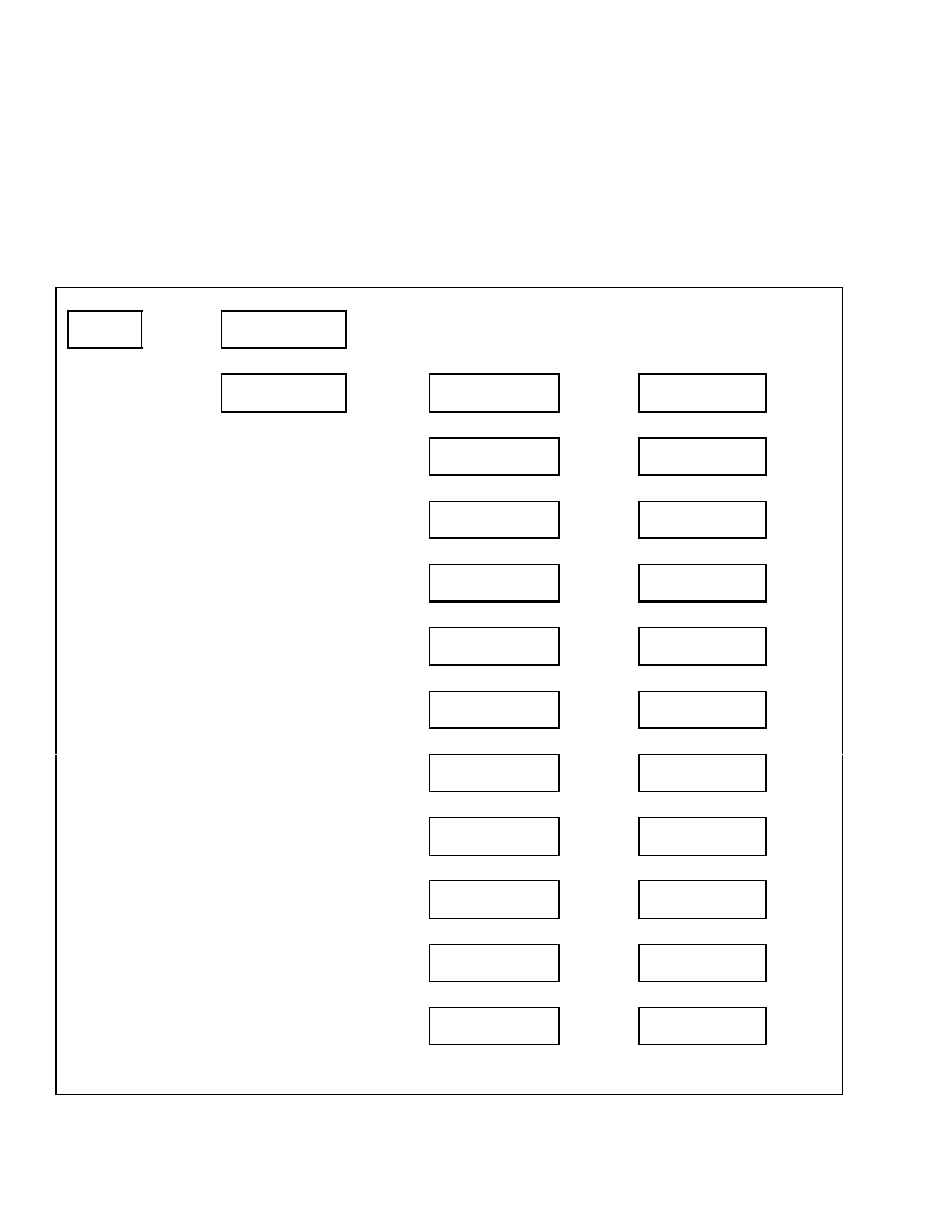
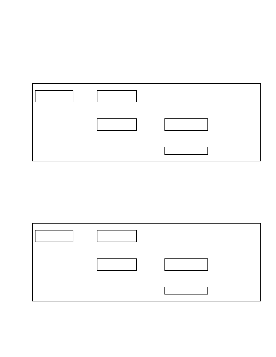
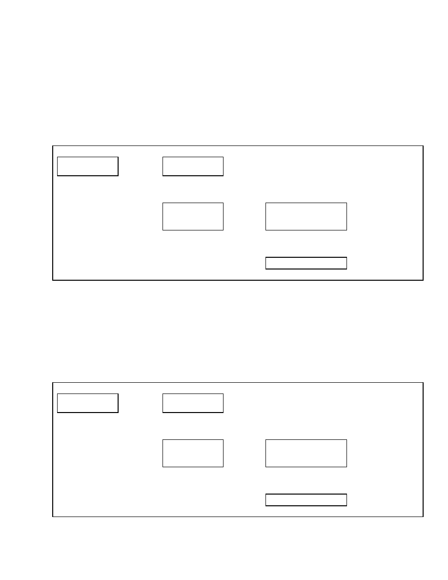
ADDING PASSWORDS
After entering the Add Password menu, enter the
new user’s five-digit password using the number
keys and press the
*
key to add the password. See
Table 3. You will be asked to enter the password
type.
Table 3. Add Password Menu
Passwords
Enter Password
↑
Scroll
↓
Main Menu
Passwords
Press
*
Key
Passwords
Add Password
Press
*
Key
Enter
Password
Press
*
Key
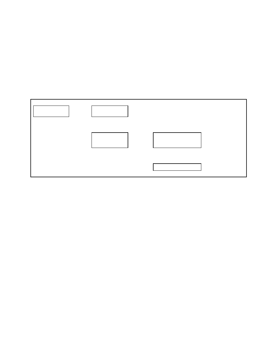
Password Type
Operator
Select One
Password Type
↑
Scroll
↓
Password Type
Lockout Reset
↑
Scroll
↓
Password Type
Supervisor
↑
Scroll
↓
Password Type
Technician
Confidential/Proprietary - Do Not Copy or Duplicate
3
Hourmeters
2200 SRM 1131
Select:
Operator – allows Truck Operation Lockout
Reset – allows Person to Reset the Password Func-
tion After Password Lockout has been Enabled.
Supervisor – allows Access to the Above Func-
tions, All Password Menu Functions, and All
Password entry Logs.
Technician – allows access to the Above Functions
and All Other Functions Listed in this Section.
See the section User Interface, Supervisor 2200
SRM 1130 for other Password Administration infor-
mation and instructions.
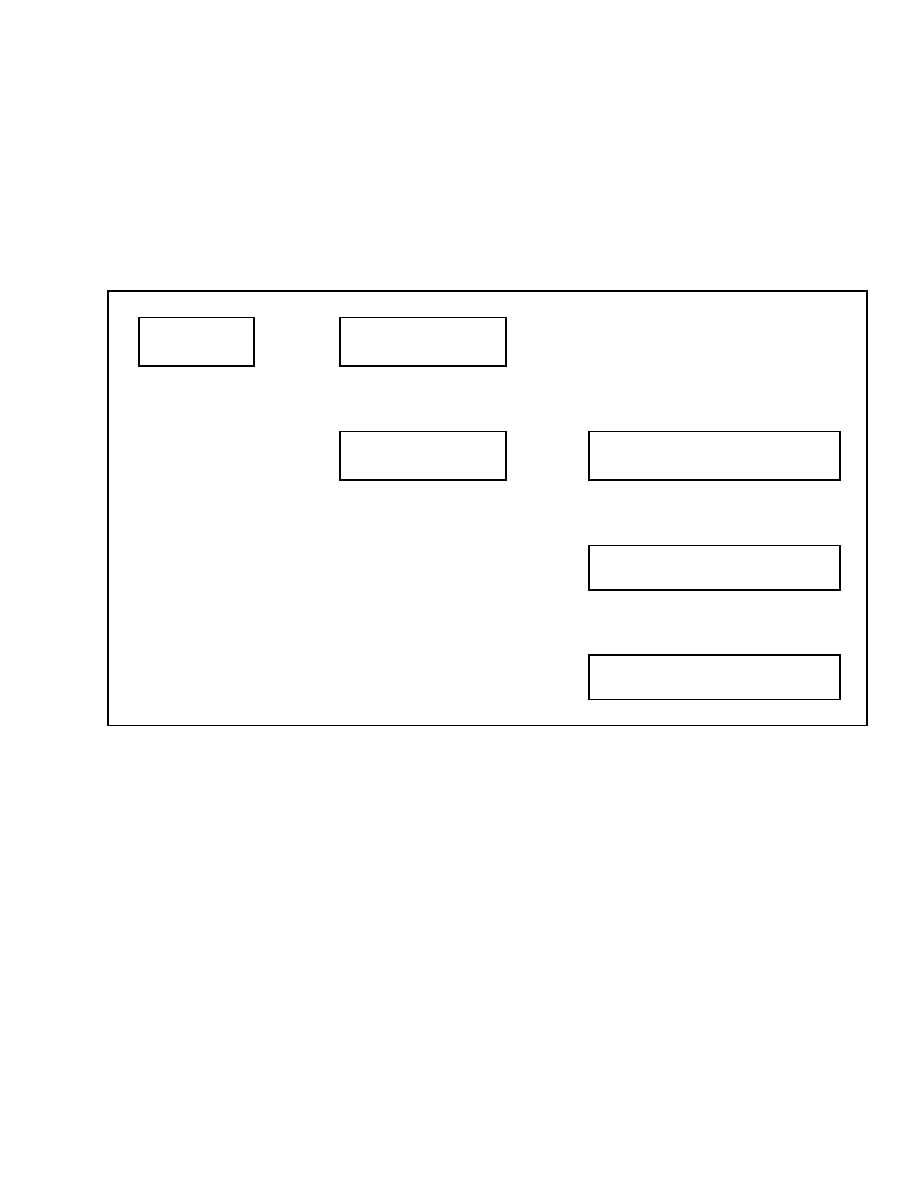
Hourmeters
This function allows the service technician access to
the various hourmeter readings available on the lift
truck. When this menu is accessed, you can view
the engine hours, system hours, and starter hours.
See Table 4. If the lift truck is equipped with op-
tional electro-hydraulics, hydraulic hours will also be
shown in the menu. The hourmeters are accessible
with the engine running.
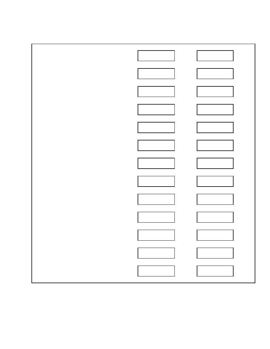
Table 4. Hourmeters Menu
Main Menu
Hourmeters
Press
*
Key
Hourmeters
Engine Hours XXXXX
When Finished Viewing, Press
*
Key to Return to the Main Menu
↑
SCROLL
↓
Hourmeters
System Hours XXXXX
↑
SCROLL
↓
Hourmeters
Hydraulic Hours XXXXX
↑
SCROLL
↓
Hourmeters
Starter Hours XXXXX
↑
SCROLL
↓
Hourmeters
Back One Level
Engine hours accumulate any time the engine is
running.
System hours accumulate anytime system power
is on.
Hydraulic hours accumulate anytime a powered
hydraulic function is being used.
Starter hours accumulate anytime the engine
starter solenoid is activated.
4
Confidential/Proprietary - Do Not Copy or Duplicate

2200 SRM 1131
View Versions
View Versions
Upon entering the View Versions Menu from the
Main Menu, the following menu functions are visible
to the service technician:
• Vehicle Systems Manager
• Dash Display
• Engine Controller
• Xmsn Controller
• Truck Serial Number
• Truck Configuration
Use the scroll keys to move to the desired function
and press the
*
key to select the function.
VSM VERSIONS
This function allows the service technician access to
the hardware, software, and configuration versions
currently installed on the lift truck.
From the View Versions menu, select the Vehicle
System Manager menu and press the
*
key. Using
the scroll keys, you can view the hardware, software,
and configuration versions of the vehicle system
manager. See Table 5. Select Back One Level, then
press the
*
key to return to the previous menu.
Table 5. View VSM Versions Menu
Main Menu
View Versions
Press
*
Key
View Versions
Vehicle Syst Manager
Press
*
Key
Vehicle Syst Manager
Hardware
XXXXXXXX
↑
SCROLL
↓
Vehicle Syst Manager
Software
XXXXXXXX
↑
SCROLL
↓
Vehicle Syst Manager
Config
XXXXXXXX
↑
SCROLL
↓
Vehicle Syst Manager
Back One Level
Confidential/Proprietary - Do Not Copy or Duplicate
5

View Versions
2200 SRM 1131
DASH DISPLAY VERSIONS
This function allows the service technician access to
the hardware, software, and configuration versions
of the dash display currently installed on the lift
truck.
From the View Versions menu, select the Dash Dis-
play menu and press the
*
key. Using the scroll keys,
you can view the hardware, software, and configura-
tion versions of the dash display. See Table 6. Select
Back One Level, then press the
*
key to return to the
previous menu.
Table 6. View Dash Display Versions Menu
Main Menu
View Versions
Press
*
Key
View Versions
Vehicle Syst Manager
↑
SCROLL
↓
View Versions
Dash Display
Press
*
Key
Dash Display
Hardware
XXXXXXXX
↑
SCROLL
↓
Dash Display
Software
XXXXXXXX
↑
SCROLL
↓
Dash Display
Config
XXXXXXXX
↑
SCROLL
↓
Dash Display
Back One Level
6
Confidential/Proprietary - Do Not Copy or Duplicate
2200 SRM 1131
View Versions
ENGINE CONTROLLER VERSION
This function allows the service technician access to
the hardware and software versions of the engine
controller currently installed on the lift truck.
From the View Versions menu, select the Engine
Controller menu and press the
*
key.
Using the
scroll keys, you can view the hardware and software
versions of the engine controller. See Table 7. Select
Back One Level, then press the
*
key to return to
the previous menu.
Table 7. View Engine Controller Versions Menu
Main Menu
View Versions
Press
*
Key
View Versions
Vehicle Syst Manager
↑
SCROLL
↓
View Versions
Engine Controller
Press
*
Key
Engine Controller
Hardware
XXXXXXXX
↑
SCROLL
↓
Engine Controller
Software
XXXXXXXX
↑
SCROLL
↓
Engine Controller
Back One Level
Confidential/Proprietary - Do Not Copy or Duplicate
7
View Versions
2200 SRM 1131
TRANSMISSION CONTROLLER VERSION
This function allows the service technician access to
the hardware and software versions of the optional
transmission controller currently installed on the lift
truck.
From the View Versions menu, select the Xmsn Con-
troller menu and press the
*
key. Using the scroll
keys, you can view the hardware and software ver-
sions of the transmission controller. See Table 8. Se-
lect Back One Level, then press the
*
key to return
to the previous menu.
Table 8. View Transmission Controller Versions Menu
Main Menu
View Versions
Press
*
Key
View Versions
Vehicle Syst Manager
↑
SCROLL
↓
View Versions
Xmsn Controller
Press
*
Key
Xmsn Controller
Hardware
XXXXXXXX
↑
SCROLL
↓
Xmsn Controller
Software
XXXXXXXX
↑
SCROLL
↓
Xmsn Controller
Back One Level
TRUCK SERIAL NUMBER
This function allows the service technician access to
the truck serial number.
From the View Versions menu, select the Truck Se-
rial Number menu and press the
*
key to view the
truck serial number. See Table 9. Select Back One
Level, then press the
*
key to return to the previous
menu.
8
Confidential/Proprietary - Do Not Copy or Duplicate
2200 SRM 1131
View Versions
Table 9. View Truck Serial Number Menu
Main Menu
View Versions
Press
*
Key
View Versions
Vehicle Syst Manager
↑
SCROLL
↓
View Versions
Truck Serial Number
Press
*
Key
Truck Serial Number
XXXXXXXXXXXXXXX
↑
SCROLL
↓
Truck Serial Number
Back One Level
TRUCK CONFIGURATION
This function allows the service technician to view
the codes for the truck configuration.
From the View Versions menu, select the Truck Con-
fig menu and press the
*
key. Use the scroll keys
to view the truck configuration codes. See Table 10.
Press the
*
key to return to the previous menu.
Table 10. View Truck Configuration Menu
Main Menu
View Versions
Press
*
Key
View Versions
Vehicle Syst Manager
↑
SCROLL
↓
View Versions
Truck Config
Press
*
Key
Truck Config 0
XXXXXXXXXXXXXXXXX
When Finished
Viewing, Press
*
Key to Go Back
One Level
↑
SCROLL
↓
Truck Config 1
XXXXXXXXXXXXXXXXX
↑
SCROLL
↓
Truck Config 2
XXXXXXXXXXXXXXXXX
Confidential/Proprietary - Do Not Copy or Duplicate
9

Diagnostics
2200 SRM 1131
Diagnostics
Upon entering the Diagnostics Menu from the Main
Menu, the following menu functions are visible to the
service technician:
• Clear Fault Log
• View Fault Log
• No-Run Data Display
• Engine Accelerator and Throttle Data Display
• Engine Speeds and Governor Data Display
• Engine Fuel and Emission Data Display
• Engine General Data Display
• XMSN/Brake Data Display
• Hydraulic Data Display
• General Truck Data Display
For a complete description of the Diagnostic func-
tions accessible through the Dash Display. See the
Diagnostic Troubleshooting Manual 9000 SRM
1112.
Use the scroll keys to move to the desired function
and press the
*
key to select the function.
CLEAR FAULT LOG
This function will allow the service technician to
clear all fault log entries from the VSM. See Ta-
ble 11.
Table 11. Clear Fault Log
Main Menu
Diagnostics
Press
*
Key
Diagnostics
Clear Fault Log
Press
*
Key
Clear Fault Log
No?
Press
*
Key
↑
SCROLL
↓
Clear Fault Log
Yes?
Press
*
Key
10
Confidential/Proprietary - Do Not Copy or Duplicate

2200 SRM 1131
Diagnostics
VIEW FAULT LOG
This function will allow the service technician to view
all faults stored in the VSM. All fault codes will be
displayed with the most recent fault listed first. See
Table 12.
Table 12. View Fault Log
Main Menu
Diagnostics
Press
*
Key
Diagnostics
Clear Fault Log
↑
SCROLL
↓
Diagnostics
View Fault Log
Press
*
Key
VSM
1st
123456-12
#
9 Last
9
12 Press
*
Key
↑
SCROLL
↓
Hydr
1st
123457- 2
#
11 Last
1
11
Press
*
Key
↑
SCROLL
↓
ECU
1st
111111- 3 #
5 Last
12
9
Press
*
Key
Confidential/Proprietary - Do Not Copy or Duplicate
11
Diagnostics
2200 SRM 1131
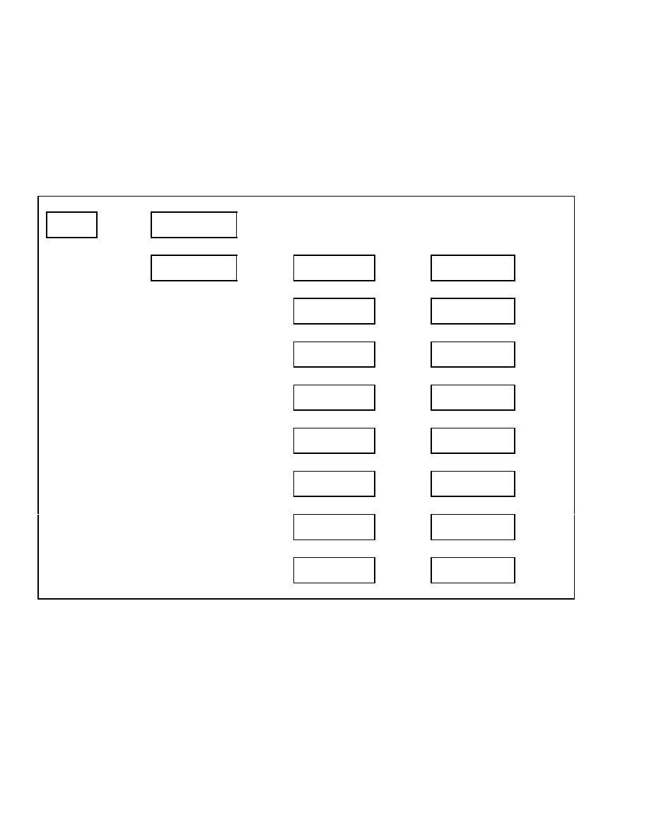
NO-RUN DATA DISPLAY
This function will allow the service technician to view
inputs or values listed in the menu when the engine
is not running. Use the scroll keys to move to the de-
sired function and press the
*
key to select the func-
tion. See Table 13. When finished viewing an input
or value, press the
*
key to return to the previous
menu.
NOTE: Depending on how an individual lift truck is
equipped, some functions shown in the menu may not
be available for viewing.
Table 13. No-Run Data Display
Main Menu
Diagnostics
Press
*
Key
Diagnostics
Clear Fault Log
↑
Scroll
↓
Diagnostics
No-Run Data Display
Press
*
Key
No-Run Data Display
Accelerator Pedal A
Press
*
Key
Accelerator Pedal A
XXXXX Volts
Press
*
Key
↑
Scroll
↓
No-Run Data Display
Accelerator Pedal B
Press
*
Key
Accelerator Pedal B
XXXXX Volts
Press
*
Key
↑
Scroll
↓
No-Run Data Display
Throttle Position A
Press
*
Key
Throttle Position A
XXXXX Volts
Press
*
Key
↑
Scroll
↓
No-Run Data Display
Throttle Position B
Press
*
Key
Throttle Position B
XXXXX Volts
Press
*
Key
↑
Scroll
↓
No-Run Data Display
Hyd Lift/Lower Input
Press
*
Key
Hyd Lift/Lower Input
XX%
Press
*
Key
↑
Scroll
↓
No-Run Data Display
Hydraulic Tilt Input
Press
*
Key
Hydraulic Tilt Input
XX%
Press
*
Key
↑
Scroll
↓
No-Run Data Display
Hydraulic Aux 1 Input
Press
*
Key
Hydraulic Aux 1 Input
XX%
Press
*
Key
↑
Scroll
↓
No-Run Data Display
Hydraulic Aux 2 Input
Press
*
Key
Hydraulic Aux 2 Input
XX%
Press
*
Key
12
Confidential/Proprietary - Do Not Copy or Duplicate
2200 SRM 1131
Diagnostics
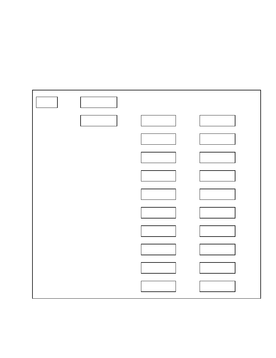
ENGINE ACCELERATOR AND THROTTLE
DATA DISPLAY
This function will allow the service technician to view
all inputs and other values associated with the accel-
erator and throttle sensors while the engine is oper-
ating. Use the scroll keys to move to the desired func-
tion and press the
*
key to select the function. See
Table 14. When finished viewing an input or value,
press the
*
key to return to the previous menu.
NOTE: Depending on how an individual lift truck is
equipped, some functions shown in the menu may not
be available for viewing.
Table 14. Engine Accelerator and Throttle Data Display
Main Menu
Diagnostics
Press
*
Key
Diagnostics
Clear Fault Log
↑
Scroll
↓
Diagnostics
Engine Accel & Throt
Press
*
Key
Engine Accel & Throt
Accelerator Pedal A
Press
*
Key
Accelerator Pedal A
XXXXX Volts
Press
*
Key
↑
Scroll
↓
Engine Accel & Throt
Accelerator Pedal B
Press
*
Key
Accelerator Pedal B
XXXXX Volts
Press
*
Key
↑
Scroll
↓
Engine Accel & Throt
Accelerator Pedal %
Press
*
Key
Accelerator Pedal %
XX%
Press
*
Key
↑
Scroll
↓
Engine Accel & Throt
Throttle Position A
Press
*
Key
Throttle Position A
XXXXX Volts
Press
*
Key
↑
Scroll
↓
Engine Accel & Throt
Throttle Position B
Press
*
Key
Throttle Position B
XXXXX Volts
Press
*
Key
↑
Scroll
↓
Engine Accel & Throt
Accelerator Pedal %
Press
*
Key
Accelerator Pedal %
XX%
Press
*
Key
↑
Scroll
↓
Engine Accel & Throt
Cable-Actuated TPS
Press
*
Key
Cable-Actuated TPS
XXXXX Volts
Press
*
Key
↑
Scroll
↓
Engine Accel & Throt
Gasoline ECU TPS
Press
*
Key
Gasoline ECU TPS
XXXXX Volts
Press
*
Key
↑
Scroll
↓
Engine Accel & Throt
Throt Sens Supply A
Press
*
Key
Throt Sens Supply A
XXXXX Volts
Press
*
Key
↑
Scroll
↓
Engine Accel & Throt
Throt Sens Supply B
Press
*
Key
Throt Sens Supply B
XXXXX Volts
Press
*
Key
Confidential/Proprietary - Do Not Copy or Duplicate
13
Diagnostics
2200 SRM 1131
ENGINE SPEEDS AND GOVERNOR DATA
DISPLAY
This function will allow the service technician to
view all inputs and other values associated with the
speeds and governing of the engine control system
while the engine is operating. Use the scroll keys
to move to the desired function and press the
*
key
to select the function. See Table 15. When finished
viewing an input or value, press the
*
key to return
to the previous menu.
NOTE: Depending on how an individual lift truck is
equipped, some functions shown in the menu may not
be available for viewing.
Table 15. Engine Speeds and Governor Data Display
Main Menu
Diagnostics
Press
*
Key
Diagnostics
Clear Fault Log
↑
Scroll
↓
Diagnostics
Engine Speeds & Gov
Press
*
Key
Engine Speeds & Gov
Engine Speed (RPM)
Press
*
Key
Engine Speed (RPM)
XXXX RPM
Press
*
Key
↑
Scroll
↓
Engine Speeds & Gov
Gasoline ECU Speed
Press
*
Key
Gasoline ECU Speed
XXXX RPM
Press
*
Key
↑
Scroll
↓
Engine Speeds & Gov
Requested Speed
Press
*
Key
Requested Speed
XXXX RPM
Press
*
Key
↑
Scroll
↓
Engine Speeds & Gov
Target Idle Speed
Press
*
Key
Target Idle Speed
XXXX RPM
Press
*
Key
↑
Scroll
↓
Engine Speeds & Gov
Governed Speed
Press
*
Key
Governed Speed
XXXX RPM
Press
*
Key
↑
Scroll
↓
Engine Speeds & Gov
Governing Status
Press
*
Key
Governing Status
XX
Press
*
Key
↑
Scroll
↓
Engine Speeds & Gov
Torque Mode
Press
*
Key
Torque Mode
XX
Press
*
Key
↑
Scroll
↓
Engine Speeds & Gov
Actual Engine Torque
Press
*
Key
Actual Engine Torque
XX%
Press
*
Key
↑
Scroll
↓
Engine Speeds & Gov
Requested Torque
Press
*
Key
Requested Torque
XX%
Press
*
Key
14
Confidential/Proprietary - Do Not Copy or Duplicate
2200 SRM 1131
Diagnostics
ENGINE FUEL AND EMISSIONS DATA
DISPLAY
This function will allow the service technician to view
inputs and other values associated with the engine
fuel and emissions control system while the engine
is operating. Use the scroll keys to move to the de-
sired function and press the
*
key to select the func-
tion. See Table 16. When finished viewing an input
or value, press the
*
key to return to the previous
menu.
NOTE: Depending on how an individual lift truck is
equipped, some functions shown in the menu may not
be available for viewing.
Table 16. Engine Fuel and Emissions Data Display
Main Menu
Diagnostics
Press
*
Key
Diagnostics
Clear Fault Log
↑
Scroll
↓
Diagnostics
Engine Fuel & Emissn
Press
*
Key
Engine Fuel & Emissn
Actual Ign Timing
Press
*
Key
Actual Ign Timing
XX
Press
*
Key
↑
Scroll
↓
Engine Fuel & Emissn
Desired Ign Timing
Press
*
Key
Desired Ign Timing
XX
Press
*
Key
↑
Scroll
↓
Engine Fuel & Emissn
Inlet Air Temp
Press
*
Key
Inlet Air Temp
XXX F
Press
*
Key
↑
Scroll
↓
Engine Fuel & Emissn
Manifold Abs Press
Press
*
Key
Manifold Abs Press
X PSI
Press
*
Key
↑
Scroll
↓
Engine Fuel & Emissn
Fuel Pump Status
Press
*
Key
Fuel Pump Status
X
Press
*
Key
↑
Scroll
↓
Engine Fuel & Emissn
Fuel Ctrl Status Sn1
Press
*
Key
Fuel Ctrl Status Sn1
X
Press
*
Key
↑
Scroll
↓
Engine Fuel & Emissn
Fuel Ctrl Status Sn2
Press
*
Key
Fuel Ctrl Status Sn2
X
Press
*
Key
↑
Scroll
↓
Engine Fuel & Emissn
Short Term FuelTrim1
Press
*
Key
Short Term FuelTrim1
XX%
Press
*
Key
↑
Scroll
↓
Engine Fuel & Emissn
Short Term FuelTrim2
Press
*
Key
Short Term FuelTrim2
XX%
Press
*
Key
↑
Scroll
↓
Confidential/Proprietary - Do Not Copy or Duplicate
15
Diagnostics
2200 SRM 1131
Table 16. Engine Fuel and Emissions Data Display (Continued)
Engine Fuel & Emissn
Long Term Fuel Trim
Press
*
Key
Long Term Fuel Trim
XX%
Press
*
Key
↑
Scroll
↓
Engine Fuel & Emissn
Oxygen Sensor 1 Volt
Press
*
Key
Oxygen Sensor 1 Volt
XXXX Volts
Press
*
Key
↑
Scroll
↓
Engine Fuel & Emissn
Oxygen Sensor 2 Volt
Press
*
Key
Oxygen Sensor 2 Volt
XXXX Volts
Press
*
Key
↑
Scroll
↓
Engine Fuel & Emissn
O2 Sensor1 Heat Duty
Press
*
Key
O2 Sensor1 Heat Duty
XX%
Press
*
Key
↑
Scroll
↓
Engine Fuel & Emissn
O2 Sensor2 Heat Duty
Press
*
Key
O2 Sensor2 Heat Duty
XX%
Press
*
Key
↑
Scroll
↓
Engine Fuel & Emissn
Idle Air Ctrl Valve
Press
*
Key
Idle Air Ctrl Valve
XX%
Press
*
Key
↑
Scroll
↓
Engine Fuel & Emissn
Test Mode Status
Press
*
Key
Test Mode Status
X
Press
*
Key
16
Confidential/Proprietary - Do Not Copy or Duplicate
2200 SRM 1131
Diagnostics
ENGINE GENERAL DATA DISPLAY
This function allows the service technician to view
inputs and other values associated with the general
engine control system while the engine is operating.
Use the scroll keys to move to the desired function
and press the
*
key to select the function. See Ta-
ble 17. When finished viewing an input or value,
press the
*
key to return to the previous menu.
NOTE: Depending on how an individual lift truck is
equipped, some functions shown in the menu may not
be available for viewing.
Table 17. Engine General Data Display
Main Menu
Diagnostics
Press
*
Key
Diagnostics
Clear Fault Log
↑
Scroll
↓
Diagnostics
Engine General Data
Press
*
Key
Engine General Data
Engine Coolant Temp
Press
*
Key
Engine Coolant Temp
XXX F
Press
*
Key
↑
Scroll
↓
Engine General Data
Coolant Temp - ECU
Press
*
Key
Coolant Temp - ECU
XXX F
Press
*
Key
↑
Scroll
↓
Engine General Data
Engine Oil Pressure
Press
*
Key
Engine Oil Pressure
XX PSI
Press
*
Key
↑
Scroll
↓
Engine General Data
Engine Starter Output
Press
*
Key
XXXXXXXXXXXXXXX
XXX
Press
*
Key
↑
Scroll
↓
Engine General Data
ECU Battery Voltage
Press
*
Key
ECU Battery Voltage
XXXX Volts
Press
*
Key
↑
Scroll
↓
Engine General Data
ECU Ignition Voltage
Press
*
Key
ECU Ignition Voltage
XXXX Volts
Press
*
Key
↑
Scroll
↓
Engine General Data
Malfunction Light
Press
*
Key
Malfunction Light
X
Press
*
Key
↑
Scroll
↓
Engine General Data
ECU Make
Press
*
Key
ECU Make
XXX
Press
*
Key
↑
Scroll
↓
Engine General Data
ECU Model
Press
*
Key
ECU Model
XXX
Press
*
Key
Confidential/Proprietary - Do Not Copy or Duplicate
17
Diagnostics
2200 SRM 1131
XMSN/BRAKE DATA DISPLAY
This function will allow the service technician to view
inputs from the Transmission and Braking systems
while the engine is running. Use the scroll keys to
move to the desired function and press the
*
key to
select the function. See Table 18. When finished
viewing an input or value, press the
*
key to return
to the previous menu.
NOTE: Depending on how an individual lift truck is
equipped, some functions shown in the menu may not
be available for viewing.
Table 18. XMSN Brake Data Display
Main Menu
Diagnostics
Press
*
Key
Diagnostics
Fault Logs
↑
Scroll
↓
Diagnostics
XMSN/Brake Data Disp
Press
*
Key
XMSN/Brake Data Display
Forward Switch
Press
*
Key
Forward Switch
Switch XXXXXX
Press
*
Key
↑
Scroll
↓
XMSN/Brake Data Display
Reverse Switch
Press
*
Key
Reverse Switch
Switch XXXXXX
Press
*
Key
↑
Scroll
↓
XMSN/Brake Data Display
Brake Pressure
Press
*
Key
Brake Pressure
XXX psi
Press
*
Key
↑
Scroll
↓
XMSN/Brake Data Display
Parking Brake Sensor
Press
*
Key
Parking Brake Sensor
XXXX Volts
Press
*
Key
↑
Scroll
↓
XMSN/Brake Data Display
Inch/Brake Position
Press
*
Key
Inch/Brake Position
XXXX Volts
Press
*
Key
↑
Scroll
↓
XMSN/Brake Data Display
Brake Fluid Level
Press
*
Key
Brake Fluid Level
Switch Open
Press
*
Key
↑
Scroll
↓
XMSN/Brake Data Display
Xmsn Input Speed
Press
*
Key
Xmsn Input Speed
XXXX RPM
Press
*
Key
↑
Scroll
↓
XMSN/Brake Data Display
Xmsn Output Speed
Press
*
Key
Xmsn Output Speed
XXXX RPM
Press
*
Key
↑
Scroll
↓
XMSN/Brake Data Display
Xmsn Forward 1 Pressure
Press
*
Key
Xmsn Forward 1 Pressure
XXX psi
Press
*
Key
↑
Scroll
↓
XMSN/Brake Data Display
Xmsn Forward 2 Pressure
Press
*
Key
Xmsn Forward 2 Pressure
XXX psi
Press
*
Key
↑
Scroll
↓
XMSN/Brake Data Display
Xmsn Reverse Pressure
Press
*
Key
Xmsn Reverse Pressure
XXX psi
Press
*
Key
↑
Scroll
↓
XMSN/Brake Data Display
Xmsn Oil Temp
Press
*
Key
Xmsn Oil Temp
XXX F
Press
*
Key
↑
Scroll
↓
18
Confidential/Proprietary - Do Not Copy or Duplicate
2200 SRM 1131
Diagnostics
Table 18. XMSN Brake Data Display (Continued)
XMSN/Brake Data Display
Xmsn Forward 1 Valve
Press
*
Key
Xmsn Forward 1 Valve
XXX Amps
Press
*
Key
↑
Scroll
↓
XMSN/Brake Data Display
Xmsn Forward 2 Valve
Press
*
Key
Xmsn Forward 2 Valve
XXX Amps
Press
*
Key
↑
Scroll
↓
XMSN/Brake Data Display
Xmsn Reverse Valve
Press
*
Key
Xmsn Reverse Valve
XXX Amps
Press
*
Key
↑
Scroll
↓
XMSN/Brake Data Display
Travel Speed Sensor
Press
*
Key
Travel Speed Sensor
Speed XX MPH
Press
*
Key
Confidential/Proprietary - Do Not Copy or Duplicate
19
Diagnostics
2200 SRM 1131
HYDRAULIC DATA DISPLAY
This function will allow the service technician to view
inputs and values from the hydraulic system while
the engine is running. Use the scroll keys to move
to the desired function and press the
*
key to select
the function. See Table 19. When finished viewing
an input or value, press the
*
key to return to the
previous menu.
NOTE: Depending on how an individual lift truck is
equipped, some functions shown in the menu may not
be available for viewing.
Table 19. Hydraulic Data Display
Main Menu
Diagnostics
Press
*
Key
Diagnostics
Fault Logs
↑
Scroll
↓
Diagnostics
Hydraulic Data Display
Press
*
Key
Hydraulic Data Display
Lift Height Sensor
Press
*
Key
Lift Height Sensor
XXXX Volts
Press
*
Key
↑
Scroll
↓
Hydraulic Data Display
Tilt Stop Sensor
Press
*
Key
Tilt Stop Sensor
XXXX Volts
Press
*
Key
↑
Scroll
↓
Hydraulic Data Display
Lift Valve Output
Press
*
Key
Lift Valve Output
XXXX Amps
Press
*
Key
↑
Scroll
↓
Hydraulic Data Display
Lower Valve Output
Press
*
Key
Lower Valve Output
XXXX Amps
Press
*
Key
↑
Scroll
↓
Hydraulic Data Display
Tilt Fw Valve Output
Press
*
Key
Tilt Fw Valve Output
XXXX Amps
Press
*
Key
↑
Scroll
↓
Hydraulic Data Display
Tilt Bk Valve Output
Press
*
Key
Tilt Bk Valve Output
XXXX Amps
Press
*
Key
↑
Scroll
↓
Hydraulic Data Display
Aux 1 Output Dir A
Press
*
Key
Aux 1 Output Dir A
XXXX Amps
Press
*
Key
↑
Scroll
↓
Hydraulic Data Display
Aux 1 Output Dir B
Press
*
Key
Aux 1 Output Dir B
XXXX Amps
Press
*
Key
↑
Scroll
↓
Hydraulic Data Display
Aux 2 Output Dir A
Press
*
Key
Aux 2 Output Dir A
XXXX Amps
Press
*
Key
↑
Scroll
↓
Hydraulic Data Display
Aux 2 Output Dir B
Press
*
Key
Aux 2 Output Dir B
XXXX Amps
Press
*
Key
↑
Scroll
↓
Hydraulic Data Display
Aux 3 Output Dir A
Press
*
Key
Aux 3 Output Dir A
XXXX Amps
Press
*
Key
↑
Scroll
↓
20
Confidential/Proprietary - Do Not Copy or Duplicate
2200 SRM 1131
Diagnostics
Table 19. Hydraulic Data Display (Continued)
Hydraulic Data Display
Aux 3 Output Dir B
Press
*
Key
Aux 3 Output Dir B
XXXX Amps
Press
*
Key
↑
Scroll
↓
Hydraulic Data Display
Manual Interlock Out
Press
*
Key
Manual Interlock Out
XXXXXXXXXX
Press
*
Key
↑
Scroll
↓
Hydraulic Data Display
Hyd Lift/Lower Input
Press
*
Key
Hyd Lift/Lower Input
XX%
Press
*
Key
↑
Scroll
↓
Hydraulic Data Display
Hydraulic Tilt Input
Press
*
Key
Hydraulic Tilt Input
XX%
Press
*
Key
↑
Scroll
↓
Hydraulic Data Display
Hydraulic Aux 1 Input
Press
*
Key
Hydraulic Aux 1 Input
XX%
Press
*
Key
↑
Scroll
↓
Hydraulic Data Display
Hydraulic Aux 2 Input
Press
*
Key
Hydraulic Aux 2 Input
XX%
Press
*
Key
↑
Scroll
↓
Hydraulic Data Display
Hydraulic Lift Pressure
Press
*
Key
Hydraulic Lift Pressure
XXXX psi
Press
*
Key
↑
Scroll
↓
Hydraulic Data Display
Hydraulic Filter
Press
*
Key
Hydraulic Filter
Switch XXXXXX
Press
*
Key
↑
Scroll
↓
Hydraulic Data Display
Hyd Funct Switch 1
Press
*
Key
Hyd Funct Switch 1
Switch XXXXXX
Press
*
Key
↑
Scroll
↓
Hydraulic Data Display
Hyd Funct Switch 2
Press
*
Key
Hyd Funct Switch 2
Switch XXXXXX
Press
*
Key
↑
Scroll
↓
Hydraulic Data Display
Hyd Funct Switch 3
Press
*
Key
Hyd Funct Switch 3
Switch XXXXXX
Press
*
Key
↑
Scroll
↓
Hydraulic Data Display
Hyd Funct Switch 4
Press
*
Key
Hyd Funct Switch 4
Switch XXXXXX
Press
*
Key
↑
Scroll
↓
Hydraulic Data Display
Armrest-Down Switch
Press
*
Key
Armrest-Down Switch
Switch XXXXXXX
Press
*
Key
Confidential/Proprietary - Do Not Copy or Duplicate
21
Diagnostics
2200 SRM 1131
GENERAL TRUCK DATA DISPLAY
This function will allow the service technician to view
inputs and values associated with the general lift
truck operation while the engine is running. Use the
scroll keys to move to the desired function and press
the
*
key to select the function. See Table 20. When
finished viewing an input or value, press the
*
key
to return to the previous menu.
Table 20. General Truck Data Display
Main Menu
Diagnostics
Press
*
Key
Diagnostics
Fault Logs
↑
Scroll
↓
Diagnostics
General Data Display
Press
*
Key
General Data Display
Truck Voltage
Press
*
Key
Truck Voltage
XXXX Volts
Press
*
Key
↑
Scroll
↓
General Data Display
Engine Cover Switch
Press
*
Key
Engine Cover Switch
Switch XXXXXX
Press
*
Key
↑
Scroll
↓
General Data Display
Seat Sensor
Press
*
Key
Seat Sensor
XXXX Volts
Press
*
Key
↑
Scroll
↓
General Data Display
Fuel Level Sensor
Press
*
Key
Fuel Level Sensor
XXXX Volts
Press
*
Key
↑
Scroll
↓
General Data Display
"1" Button
Press
*
Key
"1" Button
Switch XXXXXX
Press
*
Key
↑
Scroll
↓
General Data Display
"2" Button
Press
*
Key
"2" Button
Switch XXXXXX
Press
*
Key
↑
Scroll
↓
General Data Display
"3" Button
Press
*
Key
"3" Button
Switch XXXXXX
Press
*
Key
↑
Scroll
↓
General Data Display
Front Wiper Button
Press
*
Key
Front Wiper Button
Switch XXXXXX
Press
*
Key
↑
Scroll
↓
General Data Display
Rear Wiper Button
Press
*
Key
Rear Wiper Button
Switch XXXXXX
Press
*
Key
↑
Scroll
↓
General Data Display
Washer Button
Press
*
Key
Washer Button
Switch XXXXXX
Press
*
Key
↑
Scroll
↓
General Data Display
Left Turn Signal
Press
*
Key
Left Turn Signal
Switch XXXXXX
Press
*
Key
↑
Scroll
↓
22
Confidential/Proprietary - Do Not Copy or Duplicate
2200 SRM 1131
Diagnostics
Table 20. General Truck Data Display (Continued)
General Data Display
Right Turn Signal
Press
*
Key
Right Turn Signal
Switch XXXXXX
Press
*
Key
↑
Scroll
↓
General Data Display
Accelerometer X-axis
Press
*
Key
Accelerometer X-axis
XXXX Volts
Press
*
Key
↑
Scroll
↓
General Data Display
Accelerometer Y-axis
Press
*
Key
Accelerometer Y-axis
XXXX Volts
Press
*
Key
↑
Scroll
↓
General Data Display
Steering Wheel Sensor
Press
*
Key
Steering Wheel Sensor
XX Volts
Press
*
Key
↑
Scroll
↓
General Data Display
Steer Tire < Sensor
Press
*
Key
Steer Tire < Sensor
XX Volts
Press
*
Key
NOTE: Depending on how an individual lift truck is
equipped, some functions shown in the menu may not
be available for viewing.
Confidential/Proprietary - Do Not Copy or Duplicate
23

Set Travel and Braking
2200 SRM 1131
Set Travel and Braking
Upon entering the Set Travel and Braking menu, the
following menu functions are visible to the service
technician:
• Speed Limit
• Acceleration Rate
• Auto-Deceleration Rate
• Set Power Reversal Rate
• Set Inching/Brake Overlap
Use the scroll keys to move to the desired function
and press the
*
key to select the function.
SPEED LIMIT
If the lift truck is configured for optional speed limit,
this function can be used to adjust or deactivate the
truck speed limit. Speed may be set from a minimum
of 3 km/h (2 mph) up to the maximum allowed for the
lift truck model being adjusted. The speed may be
set in 1 km/h (0.5 mph) increments up to a maximum
speed of 24 km/h (15 mph). Setting the speed limit
higher than the maximum allowed for the lift truck
model being adjusted will cause this function to be
deactivated.
From the Set Travel and Braking menu, select Set
Speed Limit and press the
*
key. Enter the desired
limit for maximum truck speed or use the scroll keys
to select Speed Limit Off. See Table 21. Press the
*
key to save your selection and access the Exit Options
menu.
Table 21. Speed Limit Menu
Main Menu
Set Travel & Braking
Press
*
Key
Set Travel & Braking
Set Speed Limit
Press
*
Key
Set Speed Limit
Speed Limit Off
Select Maximum Speed from
Menu or Turn the Speed Limit
Off and Press
*
Key to Exit
↑
SCROLL
↓
Set Speed Limit
Max Speed 15.0 mph
↑
SCROLL
↓
Set Speed Limit
Max Speed 2.0 mph
24
Confidential/Proprietary - Do Not Copy or Duplicate
2200 SRM 1131
Set Travel and Braking
ACCELERATION RATE
If the lift truck is configured for optional DuraMatch
or DuraMatch Plus transmission, this function can
be used to adjust the travel rate of acceleration. The
rate of acceleration can be adjusted using a scale of 1
to 10. Using a setting of 10 will result in the fastest
rate of acceleration. Using a number lower than 10
will result in a slower rate of acceleration.
From the Travel and Braking menu, select Set Accel-
eration and press the
*
key. See Table 22. Select a
number from 1 to 10 and press the
*
key to save your
selection and access the Exit Options menu.
Table 22. Acceleration Rate Menu
Main Menu
Set Travel & Braking
Press
*
Key
Set Travel & Braking
Set Speed Limit
↑
SCROLL
↓
Set Travel & Braking
Set Acceleration
Press
*
Key
Set Acceleration
10
Set Acceleration Rate from 1
to 10 and Press
*
Key to Exit
↑
SCROLL
↓
Set Acceleration
1
AUTO-DECELERATION RATE
If the lift truck is configured for optional DuraMatch
or DuraMatch Plus transmission, this function can
be used to adjust the travel rate of deceleration when
the accelerator pedal is released. The rate of deceler-
ation can be adjusted using a scale of 1 to 10. Using
a setting of 10 will result in the fastest rate of decel-
eration. Using a number lower than 10 will result in
a slower rate of deceleration.
From the Travel and Braking menu, select Set Auto-
Decel and press the
*
key. See Table 23. Select a
number from 1 to 10 and press the
*
key to save your
selection and access the Exit Options menu.
Table 23. Auto-Decel Menu
Main Menu
Set Travel & Braking
Press
*
Key
Set Travel & Braking
Set Speed Limit
↑
SCROLL
↓
Set Travel & Braking
Set Auto-Decel
Press
*
Key
Set Auto-Decel
10
Set Auto-Decel Rate from 1 to
10 and Press
*
Key to Exit
↑
SCROLL
↓
Set Auto-Decel
1
Confidential/Proprietary - Do Not Copy or Duplicate
25

Set Travel and Braking
2200 SRM 1131
SET POWER REVERSAL RATE
If the lift truck is configured for optional DuraMatch
or DuraMatch Plus transmission, this function can
be used to adjust the travel rate of deceleration when
the truck is required to reverse direction while trav-
eling. The rate of deceleration can be adjusted using
a scale of 1 to 10. Using a setting of 10 will result
in the fastest rate of deceleration. Using a number
lower than 10 will result in a slower rate of deceler-
ation.
From the Travel and Braking menu, select Power Re-
versal and press the
*
key. See Table 24. Select a
number from 1 to 10 and press the
*
key to save your
selection and access the Exit Options menu.
Table 24. Power Reversal Menu
Main Menu
Set Travel & Braking
Press
*
Key
Set Travel & Braking
Set Speed Limit
↑
SCROLL
↓
Set Travel & Braking
Set Power Reversal
Press
*
Key
Set Power Reversal
10
Set Power Reversal Rate
from 1 to 10 and
Press
*
Key to Exit
↑
SCROLL
↓
Set Power Reversal
1
26
Confidential/Proprietary - Do Not Copy or Duplicate
2200 SRM 1131
Set Travel and Braking
SET INCHING/BRAKE OVERLAP
This function is available for all lift trucks except
those equipped with the optional DuraMatch Plus
transmission.
Use this function to change the
amount of overlap between the brake and the trans-
mission. The overlap can be adjusted using a scale
of 1 to 10. Using a setting of 10 will result in the
most overlap. Using a setting of 1 will result in the
transmission being decoupled before brake system
pressure begins to rise (no overlap).
Typically, overlap will be set low if high rpm hy-
draulic operation is required at low travel speeds.
High overlap is typically used to hold the lift truck
in position at low travel speed when operating on
uneven or sloped terrain.
From the Travel and Braking menu, select Set Inch/
Brk Overlap and press the
*
key. See Table 25. Select
a number from 1 to 10 and press the
*
key to save
your selection and access the Exit Options menu.
Table 25. Inch/Brake Overlap Menu
Main Menu
Set Travel & Braking
Press
*
Key
Set Travel & Braking
Set Speed Limit
↑
SCROLL
↓
Set Travel & Braking
Set Inch/Brk Overlap
Press
*
Key
Set Inch/Brk Overlap
10
Set Inch/Brake Overlap
from 1 to 10 and
Press
*
Key to Exit
↑
SCROLL
↓
Set Inch/Brk Overlap
1
Confidential/Proprietary - Do Not Copy or Duplicate
27

Setup Hydraulics
2200 SRM 1131
Setup Hydraulics
Upon entering the Setup Hydraulics Menu from the
Main Menu, the following menu functions are visible
to the service technician:
• Lift Maximum Speed
• Lower Maximum Speed
• Tilt Maximum Speed
• Aux. Function 1 Dir A Max Speed
• Aux. Function 1 Dir B Max Speed
• Aux. Function 2 Dir A Max Speed
• Aux. Function 2 Dir B Max Speed
• Aux. Function 3 Dir A Max Speed
• Aux. Function 3 Dir B Max Speed
• Lift Lower Ramp Rate
• Hyd. Aux. Ramp Rate
• Return To Set Tilt Delay/On/Off
Use the scroll keys to move to the desired function
and press the
*
key to select the function.
NOTE: For all hydraulic settings, a setting of 10 will
allow the function to operate at the maximum flow
rate of the lift truck.
LIFT MAXIMUM SPEED
If the lift truck is equipped with optional electro-hy-
draulics, this function can be used to set the maxi-
mum mast lift speed. The lift speed can be adjusted
using a scale of 1 to 10. Using a setting of 10 will
result in maximum lift speed. Using a number less
than 10 will result in a slower lift speed.
From the Setup Hydraulics menu, select Lift Max
Speed and press the
*
key. See Table 26. Select a
number from 1 to 10 and press the
*
key to save your
selection and access the Exit Options menu.
Table 26. Lift Speed Menu
Main Menu
Setup Hydraulics
Press
*
Key
Setup Hydraulics
Lift Max Speed
Press
*
Key
Lift Max Speed
10
Select Lift Maximum
Speed from 1 to 10 and
Press
*
Key to Exit
↑
SCROLL
↓
Lift Max Speed
1
LOWER MAXIMUM SPEED
If the lift truck is equipped with optional electro-hy-
draulics, this function can be used to set the maxi-
mum mast lowering speed. The lowering speed can
be adjusted using a scale of 1 to 10. Using a setting
of 10 will result in maximum lowering speed. Using
a number lower than 10 will result in a slower low-
ering speed.
From the Setup Hydraulics menu, select Lower Max
Speed and press the
*
key. See Table 27. Select a
number from 1 to 10 and press the
*
key to save your
selection and access the Exit Options menu.
28
Confidential/Proprietary - Do Not Copy or Duplicate
2200 SRM 1131
Setup Hydraulics
Table 27. Lower Speed Menu
Main Menu
Setup Hydraulics
Press
*
Key
Setup Hydraulics
Lift Max Speed
↑
SCROLL
↓
Setup Hydraulics
Lower Max Speed
Press
*
Key
Lower Max Speed
10
Set Lower Maximum
Speed from 1 to 10 and
Press
*
Key to Exit
↑
SCROLL
↓
Lower Max Speed
1
TILT MAXIMUM SPEED
If the lift truck is equipped with optional electro-hy-
draulics, this function can be used to set the maxi-
mum mast tilt speed. The tilt speed can be adjusted
using a scale of 1 to 10. Using a setting of 10 will re-
sult in maximum tilt speed. Using a number lower
than 10 will result in a slower tilt speed.
From the Setup Hydraulics menu, select Tilt Max
Speed and press the
*
key. See Table 28. Select a
number from 1 to 10 and press the
*
key to save your
selection and access the Exit Options menu.
Table 28. Tilt Speed Menu
Main Menu
Setup Hydraulics
Press
*
Key
Setup Hydraulics
Lift Max Speed
↑
SCROLL
↓
Setup Hydraulics
Tilt Max Speed
Press
*
Key
Tilt Max Speed
10
Set Tilt Maximum
Speed from 1 to 10 and
Press
*
Key to Exit
↑
SCROLL
↓
Tilt Max Speed
1
Confidential/Proprietary - Do Not Copy or Duplicate
29

Setup Hydraulics
2200 SRM 1131
AUXILIARY FUNCTION ONE, DIRECTION
A, MAXIMUM SPEED
If the lift truck is equipped with optional elec-
tro-hydraulics, this function can be used to set the
maximum auxiliary function speed in direction A.
The auxiliary function speed can be adjusted using
a scale of 1 to 10. Using a setting of 10 will result in
maximum auxiliary function speed. Using a num-
ber lower than 10 will result in a slower auxiliary
function speed.
From the Setup Hydraulics menu, select Aux 1 Max
Spd Dir A and press the
*
key. See Table 29. Select
a number from 1 to 10 and press the
*
key to save
your selection and access the Exit Options menu.
Table 29. Auxiliary Function Speed Menu
Main Menu
Setup Hydraulics
Press
*
Key
Setup Hydraulics
Lift Max Speed
↑
SCROLL
↓
Setup Hydraulics
Aux 1 Max Spd Dir A
Press
*
Key
Aux 1 Max Spd Dir A
10
Set Aux 1 Maximum
Speed Dir A from 1 to 10
and Press
*
Key to Exit
↑
SCROLL
↓
Aux 1 Max Spd Dir A
1
AUXILIARY FUNCTION ONE, DIRECTION
B, MAXIMUM SPEED
If the lift truck is equipped with optional elec-
tro-hydraulics, this function can be used to set the
maximum auxiliary function speed in direction B.
The auxiliary function speed can be adjusted using
a scale of 1 to 10. Using a setting of 10 will result in
maximum auxiliary function speed. Using a num-
ber lower than 10 will result in a slower auxiliary
function speed.
From the Setup Hydraulics menu, select Aux 1 Max
Spd Dir B and press the
*
key. See Table 30. Select
a number from 1 to 10 and press the
*
key to save
your selection and access the Exit Options menu.
Table 30. Auxiliary Function Speed Menu
Main Menu
Setup Hydraulics
Press
*
Key
Setup Hydraulics
Lift Max Speed
↑
SCROLL
↓
Setup Hydraulics
Aux 1 Max Spd Dir B
Press
*
Key
Aux 1 Max Spd Dir B
10
Set Aux 1 Maximum
Speed Dir B from 1 to 10
and Press
*
Key to Exit
↑
SCROLL
↓
Aux 1 Max Spd Dir B
1
30
Confidential/Proprietary - Do Not Copy or Duplicate
2200 SRM 1131
Setup Hydraulics
AUXILIARY FUNCTION TWO, DIRECTION
A, MAXIMUM SPEED
If the lift truck is equipped with optional electro-hy-
draulics and a four- or five-function valve, this
function can be used to set the maximum auxiliary
function speed in direction A. The auxiliary function
speed can be adjusted using a scale of 1 to 10. Using
a setting of 10 will result in maximum auxiliary
function speed. Using a number lower than 10 will
result in a slower auxiliary function speed.
From the Setup Hydraulics menu, select Aux 2 Max
Spd Dir A and press the
*
key. See Table 31. Select
a number from 1 to 10 and press the
*
key to save
your selection and access the Exit Options menu.
Table 31. Auxiliary Function Speed Menu
Main Menu
Setup Hydraulics
Press
*
Key
Setup Hydraulics
Lift Max Speed
↑
SCROLL
↓
Setup Hydraulics
Aux 2 Max Spd Dir A
Press
*
Key
Aux 2 Max Spd Dir A
10
Set Aux 2 Maximum
Speed Dir A from 1 to 10
and Press
*
Key to Exit
↑
SCROLL
↓
Aux 2 Max Spd Dir A
1
AUXILIARY FUNCTION TWO, DIRECTION
B, MAXIMUM SPEED
If the lift truck is equipped with optional electro-hy-
draulics and a four- or five-function valve, this
function can be used to set the maximum auxiliary
function speed in direction B. The auxiliary function
speed can be adjusted using a scale of 1 to 10. Using
a setting of 10 will result in maximum auxiliary
function speed. Using a number lower than 10 will
result in a slower auxiliary function speed.
From the Setup Hydraulics menu, select Aux 2 Max
Spd Dir B and press the
*
key. See Table 32. Select
a number from 1 to 10 and press the
*
key to save
your selection and access the Exit Options menu.
Table 32. Auxiliary Function Speed Menu
Main Menu
Setup Hydraulics
Press
*
Key
Setup Hydraulics
Lift Max Speed
↑
SCROLL
↓
Setup Hydraulics
Aux 2 Max Spd Dir B
Press
*
Key
Aux 2 Max Spd Dir B
10
Set Aux 2 Maximum
Speed Dir B from 1 to 10
and Press
*
Key to Exit
↑
SCROLL
↓
Aux 2 Max Spd Dir B
1
Confidential/Proprietary - Do Not Copy or Duplicate
31

Setup Hydraulics
2200 SRM 1131
AUXILIARY FUNCTION THREE,
DIRECTION A, MAXIMUM SPEED
If the lift truck is equipped with optional electro-hy-
draulics and a five-function valve, this function can
be used to set the maximum auxiliary function speed
in direction A. The auxiliary function speed can be
adjusted using a scale of 1 to 10. Using a setting of
10 will result in maximum auxiliary function speed.
Using a number lower than 10 will result in a slower
auxiliary function speed.
From the Setup Hydraulics menu, select Aux 3 Max
Spd Dir A and press the
*
key. See Table 33. Select
a number from 1 to 10 and press the
*
key to save
your selection and access the Exit Options menu.
Table 33. Auxiliary Function Speed Menu
Main Menu
Setup Hydraulics
Press
*
Key
Setup Hydraulics
Lift Max Speed
↑
SCROLL
↓
Setup Hydraulics
Aux 3 Max Spd Dir A
Press
*
Key
Aux 3 Max Spd Dir A
10
Set Aux 3 Maximum
Speed Dir A from 1 to 10
and Press
*
Key to Exit
↑
SCROLL
↓
Aux 3 Max Spd Dir A
1
AUXILIARY FUNCTION THREE,
DIRECTION B, MAXIMUM SPEED
If the lift truck is equipped with optional electro-hy-
draulics and a five-function valve, this function can
be used to set the maximum auxiliary function speed
in direction B. The auxiliary function speed can be
adjusted using a scale of 1 to 10. Using a setting of
10 will result in maximum auxiliary function speed.
Using a number lower than 10 will result in a slower
auxiliary function speed.
From the Setup Hydraulics menu, select Aux 3 Max
Spd Dir B and press the
*
key. See Table 34. Select
a number from 1 to 10 and press the
*
key to save
your selection and access the Exit Options menu.
Table 34. Auxiliary Function Speed Menu
Main Menu
Setup Hydraulics
Press
*
Key
Setup Hydraulics
Lift Max Speed
↑
SCROLL
↓
Setup Hydraulics
Aux 3 Max Spd Dir B
Press
*
Key
Aux 3 Max Spd Dir B
10
Set Aux 3 Maximum
Speed Dir B from 1 to 10
and Press
*
Key to Exit
↑
SCROLL
↓
Aux 3 Max Spd Dir B
1
32
Confidential/Proprietary - Do Not Copy or Duplicate

2200 SRM 1131
Setup Hydraulics
LIFT/LOWER RAMP RATE
If the lift truck is equipped with optional electro-hy-
draulics, this function can be used to adjust the rate
of valve opening and closing when requesting lift or
lower. This function is adjusted using only the num-
bers 1, 3, 5, 8, or 10. Using a setting of 10 will result
in the fastest opening and closing rate of the valve.
Using a setting lower than 10 will result in a slower
opening and closing rate of the valve. Changing this
function to a setting less than the factory default set-
ting of 10 will result in additional travel after the
Lift/Lower lever is returned to the neutral position.
From the Setup Hydraulics menu, select Lift/Lower
Ramp and press the
*
key. See Table 35. Select a
number (1, 3, 5, 8, or 10) and press the
*
key to save
your selection and access the Exit Options menu.
Table 35. Lift/Lower Ramp Rate Menu
Main Menu
Setup Hydraulics
Press
*
Key
Setup Hydraulics
Lift Max Speed
↑
SCROLL
↓
Setup Hydraulics
Lift/Lower Ramp
Press
*
Key
Lift/Lower Ramp
10
Set Lift/Lower Ramp
from 1 to 10 and
Press
*
Key to Exit
↑
SCROLL
↓
Lift/Lower Ramp
1
Confidential/Proprietary - Do Not Copy or Duplicate
33

Setup Hydraulics
2200 SRM 1131
HYDRAULIC AUXILIARY RAMP RATE
If the lift truck is equipped with optional electro-hy-
draulics, this function can be used to adjust the rate
of valve opening and closing when requesting any
auxiliary function. This function is adjusted using
only the numbers 1, 3, 5, 8, or 10. Using a setting
of 10 will result in the fastest opening and closing
rate of the valve. Using a setting lower than 10 will
result in a slower opening and closing rate of the
valve. Changing this function to a setting less than
the factory default setting of 10 will result in addi-
tional travel after the Hydraulic Auxiliary lever is
returned to the neutral position.
From the Setup Hydraulics menu, select Hydraulic
Aux Ramp and press the
*
key. See Table 36. Enter
a number (1, 3, 5, 8, or 10) and press the
*
key to save
your selection and access the Exit Options menu.
Table 36. Hydraulic Auxiliary Ramp Rate Menu
Main Menu
Setup Hydraulics
Press
*
Key
Setup Hydraulics
Lift Max Speed
↑
SCROLL
↓
Setup Hydraulics
Hydraulic Aux Ramp
Press
*
Key
Hydraulic Aux Ramp
10
Set Hydraulic Aux Ramp
from 1 to 10 and
Press
*
Key to Exit
↑
SCROLL
↓
Hydraulic Aux Ramp
1
34
Confidential/Proprietary - Do Not Copy or Duplicate
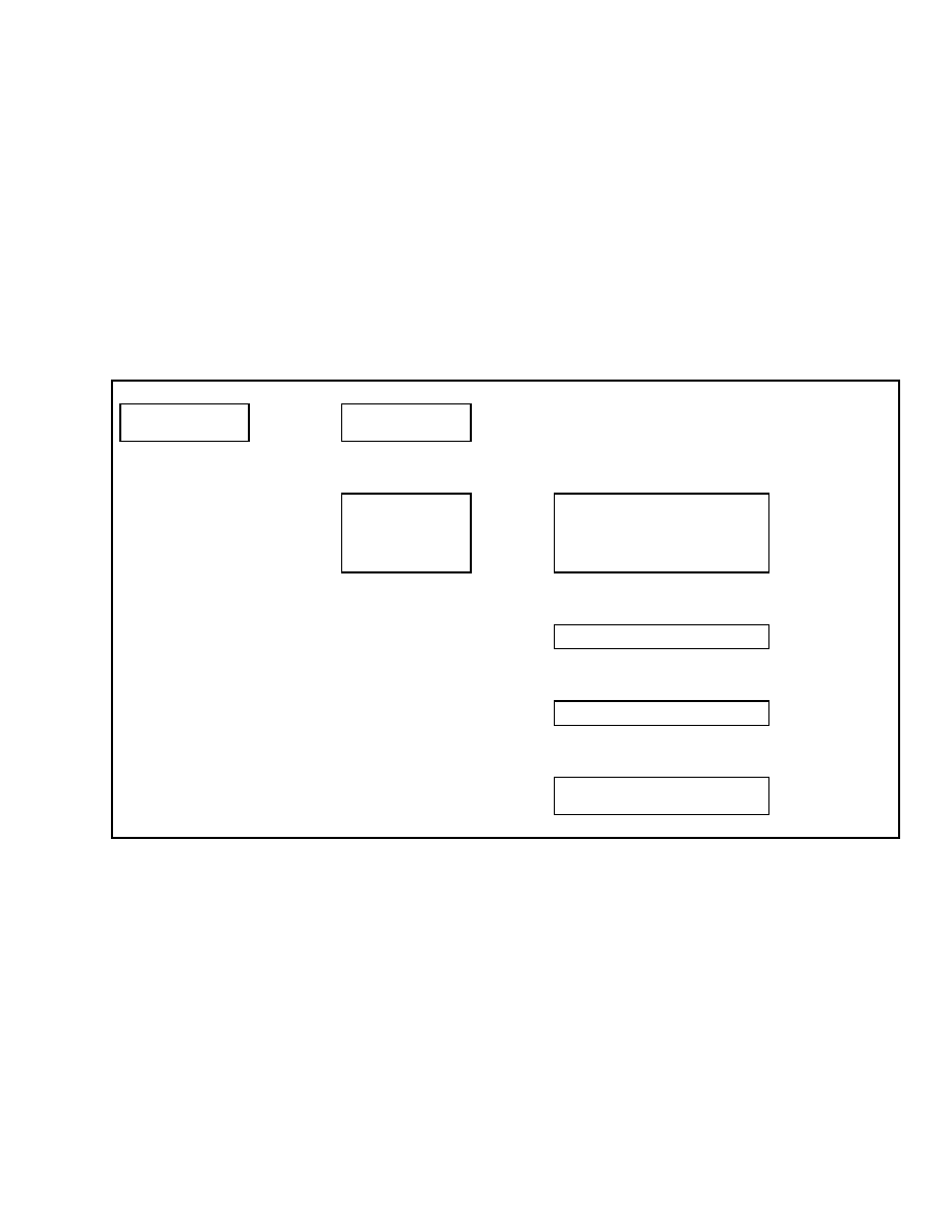
2200 SRM 1131
Setup Hydraulics
RETURN TO SET TILT DELAY/ON/OFF
If the lift truck is configured for optional return to
set tilt, this function can be used to set the time de-
lay before allowing tilt to resume. This function is
adjusted by selecting a time period from the menu
selection. The function can be set to delay from 0.1
sec. to 3.0 sec. The function can also be deactivated
using the OFF setting. Using the continuous setting
will cause tilt to stop and hold at the set point un-
til the function is returned to neutral or the override
button is pressed.
From the Setup Hydraulics menu, select Tilt Set-
Point Delay and press the
*
key. See Table 37. Us-
ing the scroll keys, select the desired setting from
the menu selections. When finished, press the
*
key
to save your selection and access the Exit Options
menu.
Table 37. Tilt Delay Menu
Main Menu
Setup Hydraulics
Press
*
Key
Setup Hydraulics
Lift Max Speed
↑
SCROLL
↓
Setup Hydraulics
Tilt Set Point Delay
Press
*
Key
Tilt Set Point Delay
Continuous
Set Tilt Set Point Delay
from 0.1 sec to 3.0
sec or Select OFF or
Continuous and Press
*
Key to Exit
↑
SCROLL
↓
Tilt Set Point Delay
3.0 sec
↑
SCROLL
↓
Tilt Set Point Delay
0.1 sec
↑
SCROLL
↓
Tilt Set Point Delay
Tilt Set Point Off
Confidential/Proprietary - Do Not Copy or Duplicate
35

Setup Display
2200 SRM 1131
Setup Display
SET SERVICE LANGUAGE
This function allows the service technician to select
the language used by the dash display. The dash dis-
play comes with English as the standard language.
A second language can be downloaded into the dash
display and selected for use.
From the Setup Display menu, select Set Service
Language and press the
*
key. Use the scroll keys
to select the desired language. See Table 38. Press
the
*
key to save your selection and access the Exit
Options menu.
Table 38. Service Language Menu
Main Menu
Setup Display
Press
*
Key
Setup Display
Set Service Language
Press
*
Key
Set Service Language
English
Select the Service
Language from the
Options Provided and
Press
*
Key to Exit
↑
SCROLL
↓
Set Service Language
Spanish
NOTE: After selecting the new language, it may take
up to 15 seconds for the new language to become ac-
tive.
36
Confidential/Proprietary - Do Not Copy or Duplicate

2200 SRM 1131
Setup General Items
Setup General Items
Upon entering the Setup General Items Menu from
the Main Menu, the following menu functions are vis-
ible to the service technician:
• Motion Alarm Activation Type
• Light Shutdown Time-Out
• Restore Default Settings
• Restore Engine Controller Default Calibration
Use the scroll keys to move to the desired function
and press the
*
key to select the function.
MOTION ALARM ACTIVATION TYPE
If the lift truck is equipped with an optional motion
alarm, this function can be used to select how the
alarm will function. The alarm can be selected to op-
erate as a backup alarm, which will operate any time
the reverse direction is selected with the travel direc-
tion control; a forward or reverse travel alarm; any
travel direction alarm; any hydraulic function alarm;
any travel or hydraulic function alarm; or the alarm
can be set to operate any time the forward direction
is selected with the travel direction control.
From the Setup General Items menu, select Alarm
Type and press the
*
key. Using the scroll keys, select
the desired alarm type. See Table 39. Press the
*
key to save your selection and access the Exit Options
menu.
Table 39. Alarm Type Menu
Main Menu
Setup General Items
Press
*
Key
Setup General Items
Alarm Type
Press
*
Key
Alarm Type
Backup
Select Alarm Type from
Menu Selections and
Press
*
Key to Exit
↑
SCROLL
↓
Alarm Type
Forward
↑
SCROLL
↓
Alarm Type
Travel
↑
SCROLL
↓
Alarm Type
Lift/Lower
↑
SCROLL
↓
Alarm Type
Travel or Lift/Lower
↑
SCROLL
↓
Alarm Type
Forward Switch
Confidential/Proprietary - Do Not Copy or Duplicate
37

Setup General Items
2200 SRM 1131
LIGHT SHUTDOWN TIME-OUT
If the lift truck is equipped with optional work lights,
this function can be used to time-delay or turn off the
work lights when system power has been turned off.
This function may be adjusted by entering a delay of
1 to 10 minutes using the menu selections. The delay
function may also be deactivated from the menu.
From the Setup General Items menu, select Light
Shutdown Time and press the
*
key. Using the scroll
keys, select the desired time delay or deactivate the
function. See Table 40. Press the
*
key to save your
selection and access the Exit Options menu.
Table 40. Light Time-Out Menu
Main Menu
Setup General Items
Press
*
Key
Setup General Items
Alarm Type
↑
SCROLL
↓
Setup General Items
Light Shutdown Time
Press
*
Key
Light Shutdown Time
10 Minutes
Select the Light
Shutdown Interval
from 1 to 10 min.
from the Menu
or Deactivate the
Function and Press
*
Key to Exit
↑
SCROLL
↓
Light Shutdown Time
1 Minute
↑
SCROLL
↓
Light Shutdown Time
Item Deactivated
38
Confidential/Proprietary - Do Not Copy or Duplicate
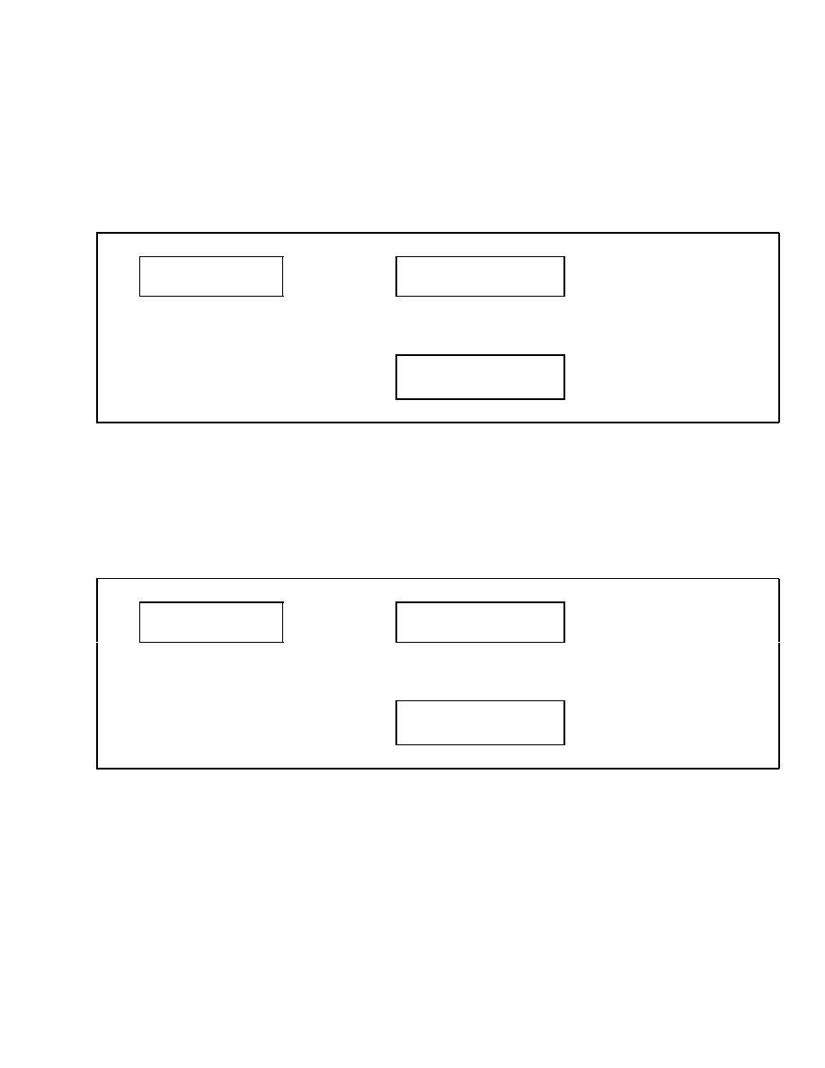
2200 SRM 1131
Setup General Items
RESTORE DEFAULT SETTINGS
This function is used to restore all service technician
adjustable truck settings to the factory default set-
tings. This function will not change any calibration
settings.
From the Setup General Items menu, select Restore
Defaults. See Table 41. Press the
*
key and proceed
to the Exit Options menu.
Table 41. Restore Defaults Menu
Main Menu
Setup General Items
Press
*
Key
Setup General Items
Alarm Type
↑
SCROLL
↓
Setup General Items
Restore Defaults
Press
*
Key to Exit and
Restore Defaults
RESTORE ENGINE CONTROLLER
DEFAULT CALIBRATION
If the lift truck is equipped with a GM engine, this
function can be used to restore the system to the fac-
tory default values.
From the Setup General Items menu, select Restore
ECU Defaults. Press the
*
key, scroll to the Exit
Options menu, and choose the Save and Exit menu
item. See Table 42. Press the
*
key to restore default
values.
Table 42. Restore Settings Menu
Main Menu
Setup General Items
Press
*
Key
Setup General Items
Alarm Type
↑
SCROLL
↓
Setup General Items
Restore ECU Defaults
Press
*
Key to Exit and
Restore Defaults
Confidential/Proprietary - Do Not Copy or Duplicate
39
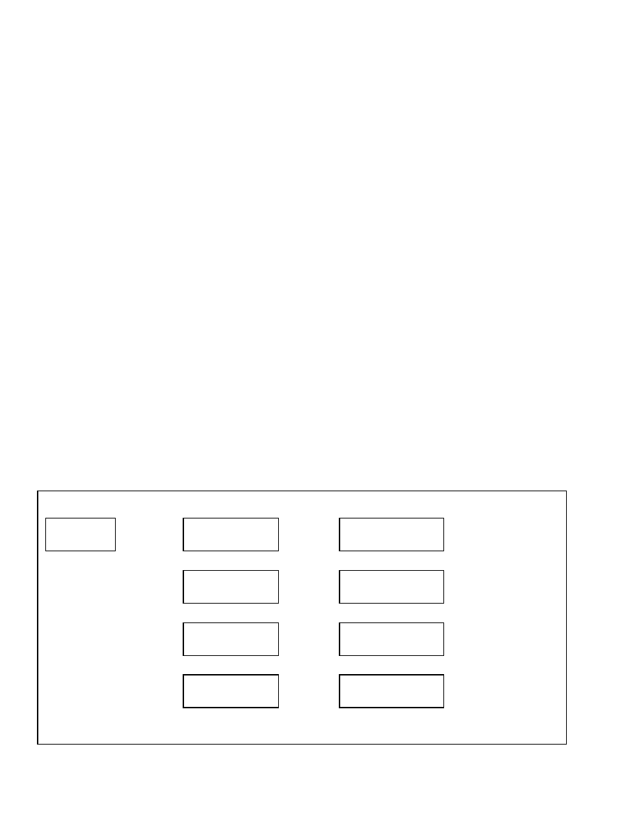
Calibrations
2200 SRM 1131
Calibrations
Upon entering the Calibrations Menu from the Main
Menu, the following menu functions are visible to the
service technician:
• Calibrate Lift Valve Output
• Calibrate Lower Valve Output
• Calibrate Tilt Back Valve Output
• Calibrate Tilt Forward Valve Output
• Calibrate Auxiliary Valve #1 Direction A Output
• Calibrate Auxiliary Valve #1 Direction B Output
• Calibrate Auxiliary Valve #2 Direction A Output
• Calibrate Auxiliary Valve #2 Direction B Output
• Calibrate Auxiliary Valve #3 Direction A Output
• Calibrate Auxiliary Valve #3 Direction B Output
• Calibrate Transmission Valve
• Set Tilt Stop Point
• Calibrate Travel Speed Sensor
• Calibrate Accelerator Pedal
NOTE: Unless otherwise specified, calibration values
are not stored in memory until the Save All Changes
menu item has been selected by pressing the
*
key.
All calibrations must be performed after replacing a
VSM.
If the lift truck is equipped with optional electro-hy-
draulics, the following functions can be used to cal-
ibrate the electro-hydraulic valve opening threshold
values for the hydraulic functions contained in the
truck configuration data file.
The functions that can be calibrated are:
• Lift Valve Output
• Lower Valve Output
• Tilt Back Valve Output
• Tilt Forward Valve Output
• Auxiliary Valve #1 Direction A Output
• Auxiliary Valve #1 Direction B Output
• Auxiliary Valve #2 Direction A Output
• Auxiliary Valve #2 Direction B Output
• Auxiliary Valve #3 Direction A Output
• Auxiliary Valve #3 Direction B Output
To perform this calibration, the lift truck must be
running and the hydraulic system at operating tem-
perature.
Start the lift truck and operate all hy-
draulic functions until the hydraulic system has been
operating for at least two minutes — this should be
sufficient to bring the hydraulic oil to operating tem-
perature.
From the Calibrations Menu, select the desired
electro-hydraulic function requiring calibration and
press the
*
key. See Table 43. With the engine at
idle, no load on the forks, and lift truck carriage in
the mast free-lift range, slowly operate the appro-
priate hydraulic control until the function selected
begins to move. Hold the control in this position and
press the
*
key.
Table 43. Calibrate Electro-Hydraulic Valve Menu
Main Menu
Calibrations
Press
*
Key
Calibrations
Lift Valve Output
Press
*
Key
Lift Valve Output
Press
*
At Creep
Press
*
Key to Proceed
With Next Function
↑
SCROLL
↓
Calibrations
Lower Valve Output
Press
*
Key
Lower Valve Output
Press
*
At Creep
Press
*
Key to Proceed
With Next Function
↑
SCROLL
↓
Calibrations
Tilt Bk Valve Output
Press
*
Key
Tilt Bk Valve Output
Press
*
At Creep
Press
*
Key to Proceed
With Next Function
↑
SCROLL
↓
Calibrations
Tilt Fw Valve Output
Press
*
Key
Tilt Fw Valve Output
Press
*
At Creep
Press
*
Key to Proceed
With Next Function
↑
SCROLL
↓
40
Confidential/Proprietary - Do Not Copy or Duplicate

2200 SRM 1131
Calibrations
Table 43. Calibrate Electro-Hydraulic Valve Menu (Continued)
Calibrations
Aux 1 Output Dir A
Press
*
Key
Aux 1 Output Dir A
Press
*
At Creep
Press
*
Key to Proceed
With Next Function
↑
SCROLL
↓
Calibrations
Aux 1 Output Dir B
Press
*
Key
Aux 1 Output Dir B
Press
*
At Creep
Press
*
Key to Proceed
With Next Function
↑
SCROLL
↓
Calibrations
Aux 2 Output Dir A
Press
*
Key
Aux 2 Output Dir A
Press
*
At Creep
Press
*
Key to Proceed
With Next Function
↑
SCROLL
↓
Calibrations
Aux 2 Output Dir B
Press
*
Key
Aux 2 Output Dir B
Press
*
At Creep
Press
*
Key to Proceed
With Next Function
↑
SCROLL
↓
Calibrations
Aux 3 Output Dir A
Press
*
Key
Aux 3 Output Dir A
Press
*
At Creep
Press
*
Key to Proceed
With Next Function
↑
SCROLL
↓
Calibrations
Aux 3 Output Dir B
Press
*
Key
Aux 3 Output Dir B
Press
*
At Creep
Press
*
Key to Proceed
With Next Function
If the calibration was successful, the program will
store the value and automatically move to the next
item in the calibration sequence.
If the calibration was not successful, the display
will read, Result Out of Range – Repeat Calibration.
Press the
*
key to repeat the calibration. Repeat the
calibration procedure until the hydraulic function
has been successfully calibrated.
At any time, use the scroll keys to access the Back
1 Level option and press the
*
key to return to the
Main Menu.
CALIBRATE TRANSMISSION VALVE
This function allows the service technician to cal-
ibrate the transmission proportional valve after a
transmission valve replacement.
NOTE: Always calibrate the transmission valve if the
valve or VSM has been replaced.
To perform this calibration, the lift truck must be
running and the transmission at operating temper-
ature. Start the lift truck and operate the lift truck
for at least two minutes — this should be sufficient
to bring the transmission to operating temperature.
WARNING
This procedure requires the engine to be run-
ning at full speed. The parking brake and ser-
vice brakes must be applied when conducting
this procedure.
To perform this procedure, the engine must be run-
ning and the parking and service brakes must be
applied. If the engine is not running, the parking
brakes are not set or the service brake pedal is not de-
pressed, the dash display will display an error mes-
sage indicating which function is not complete.
Confidential/Proprietary - Do Not Copy or Duplicate
41
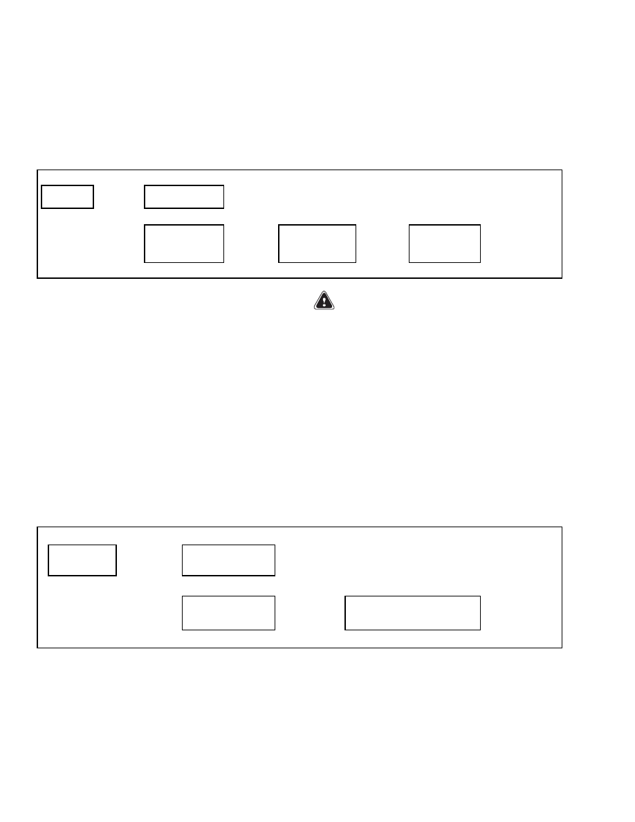
Calibrations
2200 SRM 1131
From the Calibrations menu, select Calibrate Xmsn
Valve and press the
*
key. Ensure the parking brake
is set and fully apply the service brakes. Depress
the accelerator pedal completely and maintain full
engine speed throughout the calibration procedure.
At the Calibrate Xmsn Valve - Press
*
Key to Begin
menu option, press the
*
key to begin the calibration.
See Table 44. The calibration procedure is automatic
and does not require technician input.
Table 44. Calibrate Transmission Valve Menu
Main Menu
Calibrations
Press
*
Key
Calibrations
Lift Valve Output
↑
SCROLL
↓
Calibrations
Calibrate Xmsn Valve
Press
*
Key
Calibrate Xmsn Valve
Press
*
Key to Begin
Press
*
Key
Calibrate Xmsn Valve
Done in XX
When Calibration
Complete, Will Return
to Calibration/Calibrate
Xmsn Valve Menu
After successful calibration of the transmission
valve, the dash display will automatically return
to the Calibrate Xmsn Valve menu. This completes
the calibration procedure. Scroll to the Exit Options
menu and choose the appropriate action.
NOTE: After successful calibration, the values are
automatically stored. A Save and Exit step is not nec-
essary.
SET TILT STOP POINT
If the lift truck is equipped with optional return to set
tilt, this function is used to calibrate that feature.
WARNING
This procedure requires the engine to be run-
ning. The parking and service brakes must be
applied when conducting this procedure.
From the Calibrations menu, select Set Tilt Stop
Point and press the
*
key. At the Press
*
With Mast
at Desired Stop Point menu option, adjust the mast
to the angle desired when the tilt stop point function
is activated (for example, forks horizontal, clamp
arms/pads vertical, or other features level as ap-
propriate for your attachment and application) and
press the
*
key to store the set point. See Table 45.
This completes the calibration procedure. Scroll to
the Exit Options menu and select the appropriate
action.
Table 45. Tilt Stop Point Menu
Main Menu
Calibrations
Press
*
Key
Calibrations
Lift Valve Output
↑
SCROLL
↓
Calibrations
Set Tilt Stop Point
Press
*
Key
Press
*
Key With Mast at
Desired Stop Point
Press
*
Key to
Exit
42
Confidential/Proprietary - Do Not Copy or Duplicate
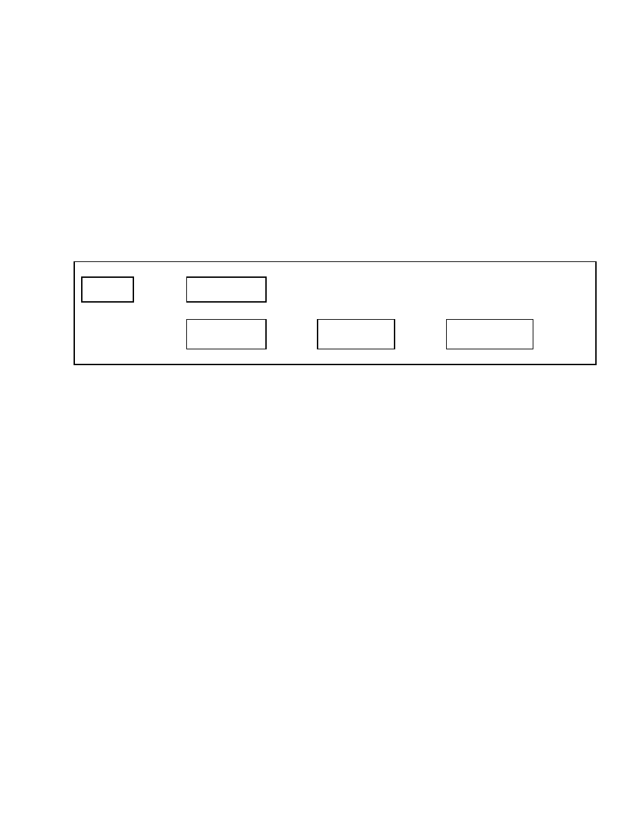
2200 SRM 1131
Calibrations
CALIBRATE TRAVEL SPEED SENSOR
If the lift truck is equipped with the optional Dura-
Match or DuraMatch Plus transmission, this func-
tion is used to calibrate the travel speed sensor. This
calibration may be needed to fine tune the system to
account for the use of non standard size tires on the
lift truck.
Mark off a straight line distance of 50 feet if the lift
truck has been programmed to use Imperial units.
Mark off a straight line distance of 15.24 meters if the
lift truck has been programmed to use Metric units.
Position the drive tires of the lift truck on the start
line of the measured distance.
From the Calibrations menu, select the Travel Speed
Sensor option and press the
*
key. See Table 46. At
the Travel Speed Sensor – Press
*
to Begin message,
press the
*
key. Drive the lift truck to the end of the
measured distance and stop with the drive tires on
the end line. At the Travel Speed Sensor – Press
*
After 50 ft. message, press the
*
key. If the calibra-
tion has been successful, the display will automati-
cally move to the Save and Exit screen.
Table 46. Travel Speed Menu
Main Menu
Calibrations
Press
*
Key
Calibrations
Lift Valve Output
↑
SCROLL
↓
Calibrations
Travel Speed Sensor
Press
*
Key
Travel Speed Sensor
Press
*
Key to Begin
Press
*
Key
Travel Speed Sensor
Press
*
Key After 50 ft
Press
*
Key to
Exit
If the calibration was not successful, a Result Out
of Range – Repeat Calibration message will be dis-
played.
Press the
*
key to recalibrate the travel
speed sensor.
Confidential/Proprietary - Do Not Copy or Duplicate
43

NOTES
____________________________________________________________
____________________________________________________________
____________________________________________________________
____________________________________________________________
____________________________________________________________
____________________________________________________________
____________________________________________________________
____________________________________________________________
____________________________________________________________
____________________________________________________________
____________________________________________________________
____________________________________________________________
____________________________________________________________
____________________________________________________________
____________________________________________________________
____________________________________________________________
____________________________________________________________
____________________________________________________________
____________________________________________________________
____________________________________________________________
44


TECHNICAL PUBLICATIONS
2200 SRM 1131
7/05 (6/05)(5/05)(12/04) Printed in United Kingdom
Document Outline
- toc
- User Interface
- Safety Precautions Maintenance and Repair
- General
- Menu Navigation
- Main Menu
- Passwords
- Hourmeters
- View Versions
- Diagnostics
- Set Travel and Braking
- Setup Hydraulics
- Lift Maximum Speed
- Lower Maximum Speed
- Tilt Maximum Speed
- Auxiliary Function One, Direction A, Maximum Speed
- Auxiliary Function One, Direction B, Maximum Speed
- Auxiliary Function Two, Direction A, Maximum Speed
- Auxiliary Function Two, Direction B, Maximum Speed
- Auxiliary Function Three, Direction A, Maximum Speed
- Auxiliary Function Three, Direction B, Maximum Speed
- Lift/Lower Ramp Rate
- Hydraulic Auxiliary Ramp Rate
- Return to Set Tilt Delay/On/Off
- Setup Display
- Setup General Items
- Calibrations
- tables
- Table 1. Password Screen
- Table 2. Exit Menu
- Table 3. Add Password Menu
- Table 4. Hourmeters Menu
- Table 5. View VSM Versions Menu
- Table 6. View Dash Display Versions Menu
- Table 7. View Engine Controller Versions Menu
- Table 8. View Transmission Controller Versions Menu
- Table 9. View Truck Serial Number Menu
- Table 10. View Truck Configuration Menu
- Table 11. Clear Fault Log
- Table 12. View Fault Log
- Table 13. No-Run Data Display
- Table 14. Engine Accelerator and Throttle Data Display
- Table 15. Engine Speeds and Governor Data Display
- Table 16. Engine Fuel and Emissions Data Display
- Table 17. Engine General Data Display
- Table 18. XMSN Brake Data Display
- Table 19. Hydraulic Data Display
- Table 20. General Truck Data Display
- Table 21. Speed Limit Menu
- Table 22. Acceleration Rate Menu
- Table 23. Auto-Decel Menu
- Table 24. Power Reversal Menu
- Table 25. Inch/Brake Overlap Menu
- Table 26. Lift Speed Menu
- Table 27. Lower Speed Menu
- Table 28. Tilt Speed Menu
- Table 29. Auxiliary Function Speed Menu
- Table 30. Auxiliary Function Speed Menu
- Table 31. Auxiliary Function Speed Menu
- Table 32. Auxiliary Function Speed Menu
- Table 33. Auxiliary Function Speed Menu
- Table 34. Auxiliary Function Speed Menu
- Table 35. Lift/Lower Ramp Rate Menu
- Table 36. Hydraulic Auxiliary Ramp Rate Menu
- Table 37. Tilt Delay Menu
- Table 38. Service Language Menu
- Table 39. Alarm Type Menu
- Table 40. Light Time-Out Menu
- Table 41. Restore Defaults Menu
- Table 42. Restore Settings Menu
- Table 43. Calibrate Electro-Hydraulic Valve Menu
- Table 44. Calibrate Transmission Valve Menu
- Table 45. Tilt Stop Point Menu
- Table 46. Travel Speed Menu
Wyszukiwarka
Podobne podstrony:
więcej podobnych podstron