
AE-117
Purdue University
Cooperative Extension Service
West Lafayette, IN 47907
ALCOHOL DISTILLATION: BASIC PRINCIPLES, EQUIPMENT,
PERFORMANCE RELATIONSHIPS, AND SAFETY
Eric Kvaalen, Doctoral Student in Chemical Engineering
Philip C. Wankat, Professor of Chemical Engineering
Bruce A. McKenzie, Extension Agricultural Engineer,
Purdue University
The purpose of this publication is to help you understand the distillation of ethyl alcohol. It first presents the
basic principles involved in distillation and how the process works. The types of distillation equipment and
systems that might be involved in a small fuel alcohol plant are then discussed, as are the performance and
control criteria needed for a general evaluation of each. The publication concludes with a discussion of safety,
along with some general selection, operation and management criteria useful in evaluating alternatives.
The information presented here hopefully will help you decide if you want to get into alcohol production, and if
so, will help you evaluate the different options that are available to you. We will only cover those distillation
processes and equipment capable of producing alcohol concentrations up to about 95.6 weight percent (wet
basis).
Remember, this publication is not a design manual. Rather its goal is to give a general understanding of
distillation processes and the performance of various equipment options in order to aid you in evaluating alcohol
production proposals and give a basis for more detailed self-study. We will not discuss fermentation processes
and equipment, or uses of the finished alcohol concentrate.
ETHYL ALCOHOL--A VIABLE ALTERNATIVE FUEL
The idea of ethyl alcohol as a liquid fuel is not new. It received considerable discussion and publicity in the
1920's and 1930's as a motor fuel. It was used as a fuel in several countries during World War II. Interest
surfaced again in the U.S. in the mid 1970's, with the advent of the oil embargo and cartel and the rapidly
escalating oil prices that resulted.

At the time of these rapid oil price increases, many people, particularly in the farming community, began to look
seriously at ethyl alcohol and gasoline/alcohol blends as alternative fuels. However, by the early 1980's,
increased U.S. oil production plus a significant drop in oil consumption due to high prices brought a
corresponding world oversupply of oil and a marked drop in oil and gasoline prices. As a result, interest in
alcohol fuels diminished sharply. Interestingly, the increased use of unleaded fuels and subsidies for fuels using
10 percent alcohol caused many oil companies to add ethyl alcohol to their gasoline as a non-lead octane
improvement additive. Such fuels are not normally advertised as gasoline/alcohol blends.
If one accepts, however, that the long range price of oil and energy will continue to increase, then ethyl alcohol
as a liquid fuel, especially for internal combustion spark ignition engines, will continue to be a potentially viable
alternative fuel source. The fact that alcohol may be profitably manufactured from a variety of crop and forest
residues, as well as from grains themselves, enhances its appeal to farm producers.
Ethyl Alcohol from "Beer"
Alcohol can be made from a variety of agricultural products by a three basic step sequence:
1. Breaking down the feed-stock (the raw material) chemically by a process which may involve cooking
and adding enzymes.
2. Fermentating, i.e., the action of micro-organisms (usually yeast) to produce a "beer" (The term "beer"
describes the liquid traction of a fermented mixture of water and ground or crushed grain that is usually
no more than 10-12% alcohol, hence the similarity of the process and the final alcohol content to that of
domestic beer.) containing a small percentage of alcohol, along with the remains of the feedstock, the
yeast cells and various other substances dissolved in water.
3. Separating the alcohol from the water and other components in the beer, usually by distillation, to
obtain the alcohol in a pure enough form to be used as fuel.
Fermenting grain (cooking it in water and treating it with enzymes to break down the starch and convert it to
sugars) results in an alcohol concentration of roughly 5-10 percent. The finished concentration or "beer"
depends on the amount of water used, the grain and the quality of the fermentation. This beer is so low in
alcohol content that it is useless as a fuel and must be further concentrated to obtain mixtures that will ignite and
burn. For this reason a distillation column is used to produce a higher alcohol concentration. (Several
publications that discuss fermentation in considerable detail are listed at the end of this publication under
"References.")
DISTILLATION--HOW IT WORKS
First of all, let's look at how distillation works. We are all generally familiar with how distilled water is
produced. The water is heated, and the steam or water vapor conducted away in a tube. If the tube is looped
downward and cooling is applied below the hump, the vapor is condensed and distilled water obtained. This is
"simple" distillation- i.e., removing a volatile substance (water) from non-volatile substances (lime, impurities,
etc.).
"Fractional" distillation is used to separate mixtures of two liquids with different boiling points, such as alcohol
and water. Ethyl alcohol with 4 percent water boils at approximately 173° F, while water boils at 212° F. A
mixture of the two liquids will boil at all temperatures between 173° and 212°, depending on the ratio of alcohol

to water.
Consider a beaker or a glass jug filled partially with a mixture of alcohol and water at some temperature. The
top of the container is closed except for a small hole, to which a balloon is attached to keep air out. Thus, the
vessel is at atmospheric pressure, but the enclosure above the liquid level is essentially undisturbed by air
currents circulating around the jug.
After a period of time, the amount of water vapor and amount of alcohol vapor contained in the gaseous mixture
above the liquid in the container will reach a constant value, depending on the temperature and pressure. The
liquid and vapor mixtures reach an "equilibrium," a condition under which there is no net change in the liquid/
vapor ratio or in the alcohol/water ratio within either the liquid or vapor mixture. However, the ratio of alcohol
to water in the vapor phase is generally greater than the ratio in the liquid phase, because alcohol is usually more
volatile than water (see Figure 1). It is this characteristic of a liquid-versus-vapor state of a substance that
permits us to distill off an increasing concentration of alcohol from the alcohol/water mixture.
By bringing about a controlled series of successive sequences re-evaporation, condensation, re-evaporation and
re-condensation), each re-condensation from the previous vapor state achieves a higher alcohol concentration.
This is because the alcohol in the vapor is at a higher concentration than was the concentration in the liquid
mixture from which it was vaporized.
Figure 1 shows the vapor-versus-liquid composition when the pressure is atmospheric. The dotted line in the
figure represents an equal concentration of alcohol in both the liquid and the vapor state. Note that the alcohol
concentration is consistently higher in the vapor phase than in the liquid phase for most of the range of the
graph. The axes are explained later.
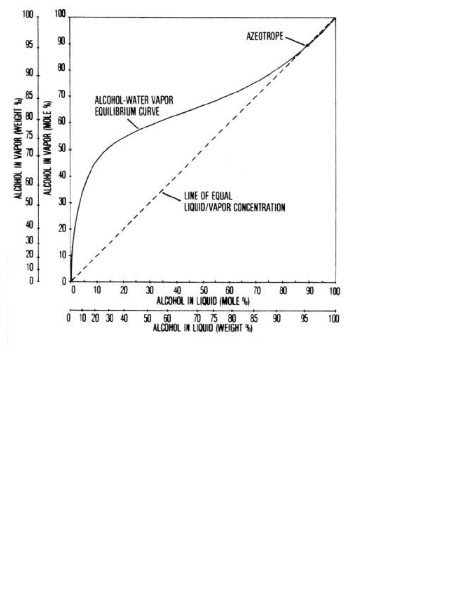
Figure 1. Equilibrium relationship between gaseous and liquid alcohol-water mixtures
(atmospheric pressure).
Azeotropic Mixtures
The previous relationships of alcohol-water mixtures hold true up to alcohol concentrations of about 95.6
percent. At this concentration, the two substances quit boiling separately (i.e., the alcohol in the vapor phase is
no longer more concentrated than in the liquid phase), and fractional distillation no longer works. A mixture of
this composition is called an "azeotropic mixture".
Generally, a third substance must be introduced into the mixture to permit separation by distillation, or some
other separation scheme must be used. The details of separating the azeotrope are discussed briefly later.
Types of Distillation Processes Most Applicable to the Farm
There are two general types of distillation processes that appear applicable to farm-size fuel alcohol production
with present technology. One is the continuous-feed distillation column system, in which a beer containing a
constant alcohol content is continuously pumped into a column. The other is a pot-type distillation system, in
which a batch of beer, with the heavy solids (spent grain) not removed, is simply boiled in place to vaporize the
alcohol. The alcohol-water vapors are then forced to flow through a distillation column to bring about
concentration.
These two processes are discussed in detail in the following pages. There are other fractional distillation systems
that may or may not use a column as we normally think of such units. They include centrifugal techniques,
mechanical rotating wipers in a tube, etc., and are not discussed here.
CONTINUOUS -FEED DISTILLATION COLUMN PROCESS
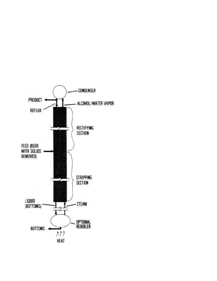
A simplified schematic of a continuous distillation column is presented in Figure 2. The column consists of a
long tube, which includes a stripping section (the lower portion) and a rectifying section (the upper portion).
There is a condenser located on the top end of the column and an optional reboiler on the bottom.
Figure 2. A continuous distillation process.
The process involves a controlled flow of liquid beer (preferably preheated and with all solids removed), which
is fed into the top of the stripping portion of the column. The liquid alcohol-water mixture (beer) trickles

downward through the column, its flow impeded or slowed by either a series of plates or continuous packing. It
passes vapor (a mixture of water vapor and alcohol vapor, but no air) which moves up. The source of the water
vapor is either steam injected from a boiler or vapor produced in the reboiler. The plates or packing serve to
cause good mixing of the vapor and liquid, allowing the alcohol to evaporate and the water to condense.
At any given point along the column, there is more alcohol in the vapor than in the liquid, but not as much as
there should be according to the equilibrium principle. Since the alcohol concentration in the vapor has not
reached equilibrium, its vapor pressure causes it to evaporate out of the liquid, and water condenses out of the
vapor.
These two processes must happen simultaneously, because the first (the vaporization) requires heat and the
second (condensation) produces heat. In a well designed and insulated column, all the heat supplied by the
condensation goes into the evaporation of the alcohol.
About the same amount of alcohol evaporates as the amount of water that condenses. Thus, the vapor (moving
up the column) constantly increases in alcohol content, whereas the liquid (flowing down) constantly loses
alcohol This means that the top of the column will have high alcohol content in both liquid and vapor, and the
bottom low in alcohol content.
The column shown can be operated either in a "continuous mode" or a "batch mode", similar to continuous
versus batch grain drying processes. The next two paragraphs describe the differences between these modes.
In a continuous operation, the column is brought to a balanced-operation state. It consists of a continuous feed
input of beer, continuous outflow of "bottoms" (Bottoms is a mixture of condensate water and some beer, in
which not all alcohol was removed or distilled), steam input from a boiler or reboiler (for process heat and to
make up for inefficiencies) and an output of highly concentrated alcohol vapor. Alcohol vapor is condensed and
a large fraction refluxed (recirculated) into the top of the column to control the final concentration of the product
output. This reflux flow is required to produce a downward flowing liquid stream in the top section of the
column. Without the reflux stream, there can be no liquid in the rectifying section of the column, which means
no separation would then occur in the rectifying section. The remaining highly-concentrated alcohol-water
condensate or distillate is collected as product. Once the column is brought into an operating balance in
"continuous mode," the operation is ideally sustained night and day, week after week, because each time it is
shut down and must be restarted, the start-up and shut-down result in appreciable losses in energy and
efficiency.
In a batch operating mode, the column is started, brought to a balanced performance and operated until the
quantity (or batch) of beer on hand is distilled. The column must then be shut down, cooled and cleaned, ready
for start-up for the next batch. Batch operation and performance will be discussed later.
Actual Operation in the Still
Let us now describe the continuous-feed distillation column process in the still as seen in Figure 2. The
"stripping" section and the "rectifying" section of the column are shown in the figure as a single vertical column
unit, which is the preferred configuration. They may, however, be built side by side, interconnected with tubing
to return the output of the stripping unit to the rectifying section and vice versa. This makes the total height
shorter, but requires a pump to lift liquid from the bottom of the second column to the top of the first. Tubing
must be quite large and well insulated. The vapor for the stripping section is supplied either by steam injected at
the bottom of the column or by the reboiler, which collects some of the liquid (mainly water) coming out the
bottom of the column and boils it to produce the vapor.

As the vapor moves out of the stripper, the rectifying section increases the alcohol concentration by allowing the
vapor flow to move up the column against some of the final liquid product flow (reflux) moving down. When
the vapor finally reaches the top of the rectifying section, it should have a concentration of 80-95 percent
alcohol, depending on the column length and the operating conditions used.
The concentrated alcohol-water vapor of 80-95 percent is then condensed to liquid in the condenser by cooling
it. Roughly 2/3 to 3/4 of the final liquid is returned to the rectifying section of the still as "reflux" (a liquid of
high alcohol concentration). It provides a highly volatile source of alcohol vapor to facilitate a high final-
product concentration and to condense out some of the remaining water vapor. This reflux is necessary to obtain
a concentrated alcohol product.
The remaining liquid flowing from the condenser (about 1/3 to 1/4 of the total) is the finished product, ready for
whatever use is intended. The ratio of amount of alcohol returned to the column to amount collected as product
is called the "reflux ratio." This ratio controls both product purity and amount of energy required for the
distillation. The higher the reflux ratio, the purer the alcohol product and the more energy that is required for
distillation.
The incoming beer feed, if well-filtered, may be used as part of the cooling fluid in the condenser. This will
bring about condensation of the reflux and finished product, while at the same time preheating the beer feed just
before it enters the stripper section. Thus, a minimum of added heat is needed to bring about the initial alcohol
vaporization (stripping) operation.
When the reflux liquid reaches the bottom of the rectifier, it enters the feed input level and joins the feed, which
is preheated beer. The mixture enriches the alcohol content of the hot beer and facilitates the vaporizing
(stripping) process as the liquids flow down against the upward flow of steam and alcohol vapor. As the steam
moves upward, it causes the alcohol to vaporize from the liquid as some of the water vapor condenses.
If the vapor composition at every point in the entire column is plotted versus the corresponding composition of
the liquid, the result is the two lines (operating lines) of Figure 3, shown superimposed on the equilibrium
diagram of Figure 1. The axes are based on how many alcohol molecules there are per hundred molecules, rather
than on a weight basis (This is because one alcohol molecule evaporates for every water molecule that
condenses: thus, the number of molecules of vapor passing a given point per second doesn't change as you move
up the column, and the same goes for the liquid. So if the stripper has, for instance, four times as many
molecules of liquid as of gas passing some point near the top, it will also have four times as many molecules of
liquid as of gas passing some other point near the bottom This means that if the molecular composition of the
gas changes by percent in a certain segment of the column, then the molecular composition of the liquid has to
change by percent in the same segment, regardless of where that segment is.) The two lines in Figure 3 are
straight, having a constant slope when axes of molecular percent are used. (Weight percent is also shown on the
horizontal axis, so conversion can be made very easily.) The slope of an operating line is directly related to the
ratio of flows of liquid to vapor: the higher the slope, the more liquid flow to vapor flow there is.
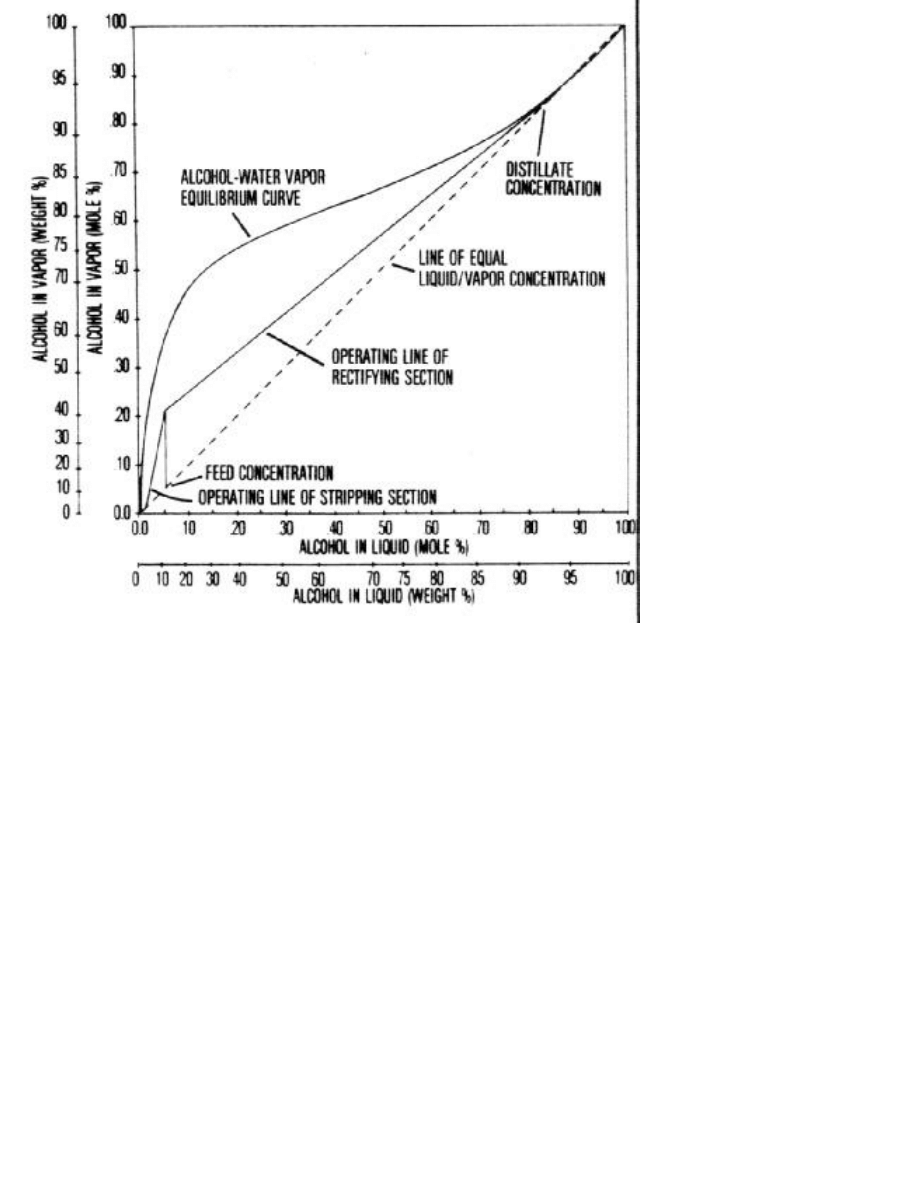
Figure 3. Operating lines for stripping and rectifying.
The "operating line" of the rectifying section intersects the dotted line of equal vapor and liquid compositions at
the high end. This is because the reflux (the liquid added at the top) was part of the vapor which has now been
condensed and now has the same composition as the vapor. The higher the alcohol concentration in the product,
the smaller will be the slope of the operating line (since operating and equilibrium lines cannot intersect) and the
greater the reflux will have to be. Hence, less product is obtained per pound of vapor if the product is higher in
alcohol, and more energy is used per pound of product.
The equilibrium curve in the figure has a "sway-back" at high concentrations. To get a product really close to
the azeotrope, the slope of the operating line must be increased to almost 45 degrees. This means increasing the
amount of reflux liquid until it almost equals the amount of vapor flowing up, thereby increasing the reflux ratio
sharply. This procedure leaves less actual product, since most of the condensed vapors have to be sent back
down the column. Consequently, it takes about twice as much energy to get a gallon of 95 percent alcohol (by
weight) as it does to get a gallon of 85 percent alcohol.
Plate or Tray-Type Columns
The length of column necessary to bring about a given concentration of final product is determined from the
operating relationships presented in Figure 3. Consider a column constructed with "plates" along its entire length
as shown in Figure 4. Liquid introduced into a plate-type column forms a shallow pool on each plate. The liquid
flows across the plate, while the gas bubbles up through holes in the plate (called a sieve tray). Each plate or tray
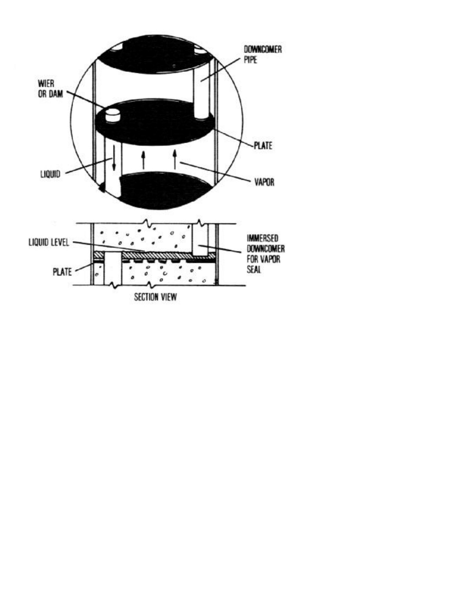
has a short section of tubing cut through the plate.
Figure 4. Sieve tray plate of a staged column. Each plate retains a liquid layer, the depth of
which is controlled by the height of the weir. The holes in each plate are small enough that the
vapor bubbles keep the liquid from passing through. The slight pressure of the alcohol-water
vapor created by the reboiler, or pot, forces the vapor to bubble through the holes, bringing
about intimate contact between the vapor (initially at lower alcohol concentration) and the
liquid (which is at slightly higher concentration). Vapor of increased alcohol concentration
leaves the surface of each successive plate while traveling upward through the column.
The assembly is similar to a toadstool, with the hollow stem positioned off to one side of the cap about 1/4 of
the way in from one edge. The top end of the tube projects above the plate surface; the lower end stops just
above the surface of the plate below. The tube is projected above the plate surface in order to form a miniature
dam (called a "weir") to maintain a depth of liquid on the plate. As the liquid level rises, overflow occurs into
the downcomer pipe to the next plate below.
The discharge end of each downcomer pipe must be positioned close to the surface of the plate below, so that
the free end will be immersed in the liquid level on that plate. This forms a liquid seal over the open end to keep
vapor from entering the pipe. By positioning successive downcomer pipes on opposite sides of each sieve tray,
the liquid flows across each plate, minimizing any stagnate flow sections and helping move any solids that
might accumulate from the distillation column.
Sometimes the holes in the sieve tray are covered with caps or checkvalves to help prevent the liquid from
coming down through the hole. If the vapor flow remains strong, however, it will prevent counterflow itself.
Ideally, when the liquid leaves a plate in its flow downward, it should be in equilibrium with the vapor flowing
upward from the same plate.
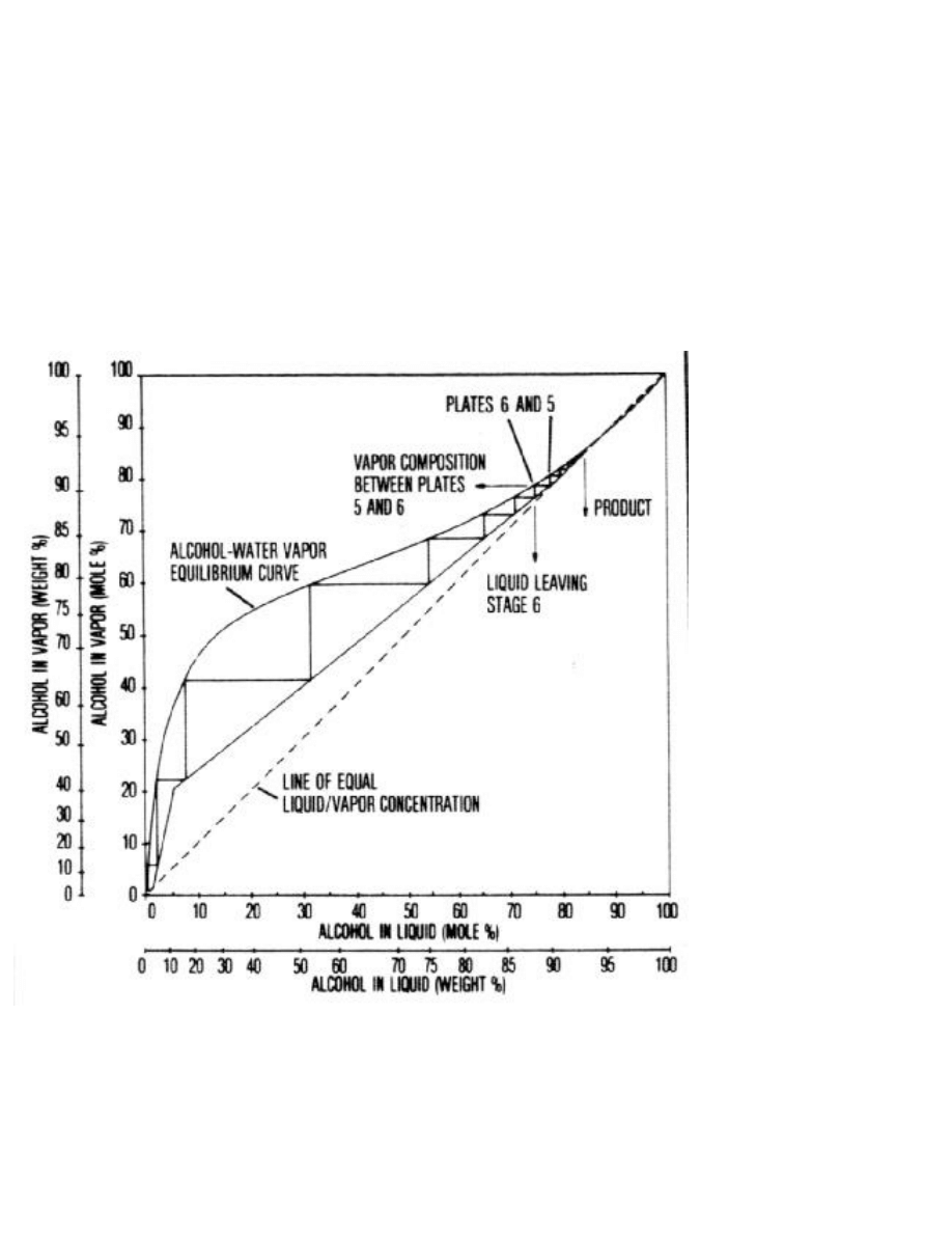
Now we have a theoretical basis to predict the alcohol content of the liquid and vapor at any plate or stage along
the column. If we want an alcohol content in the final product of 85 percent (moles per mole), then we can read
from Figure 5 what liquid concentration would be in equilibrium with the final vapor concentration (Remember,
this is the same as the product concentration.)
This liquid concentration is that which is on the surface of the top plate. If we know the composition of the
liquid flowing down the downcomer between the top plate and the second one, we can look at the operating line
on Figure 5 to determine the vapor composition flowing up between the two plates. Because the liquid
descending from the second plate must be in equilibrium with the vapor rising from it, we can now determine
the liquid composition below the second plate from the equilibrium curve.
Figure 5. Stepping-off procedure to determine the necessary number of ideal plates.
This procedure, shown on Figure 5, is the method used to determine the ideal number of stages or plates needed
for a given set of operating conditions. In actual practice, it usually takes roughly 1 1/2 to 2 times as many actual
stages as this theoretical analysis predicts. Calculations for the column design need to be precise and are usually
done by computer (Column length depends on feed concentration and desired product purity, but not on amount
of feed column diameter depends on feed flow rate and reflux ratio. Column cross sectional area is controlled by
the allowable vapor flow rate. Since vapor flow rate is directly proportional to feed rate, the column area is

directly proportional to the feed rate. Double the feed rate and the column area must double, column diameter
will be proportional to the square root of the feed rate. Vapor flow rate also increases as the reflux ratio
increases Thus, the required column diameter will also increase when the reflux ratio is increased).(Column
design is usually done by the column manufacturer, not by the user.)
Packed Columns
An alternative to a plate-type unit is the packed column. In distillation columns larger than 4 feet in diameter,
trays or plates have been found generally more economical for alcohol production. But in small columns, the
cost of fabrication, installation and maintenance of plates often makes a packed unit less expensive and more
workable.
Another consideration is the ease of cleaning deposits that may form in the course of time. In the case of plate-
type columns, deposits can sometimes be removed with a chemical rinse: other times trays may have to be
scrubbed (through portholes) or packing taken out and cleaned. Small-diameter plate columns are difficult to
clean inside, since port holes are quite small.
A packed column is filled with solid objects, with a relatively large amount of open space for liquid and vapor
flow. The objective of a packed column, as with a plate column, is to bring about intimate contact between the
liquid and the vapor without too much flow resistance. Packing objects should stack loosely in the column,
having a relatively large amount of exposed surface area, providing many surfaces for liquid and vapor flow to
intermingle.
Packing material may range in size from 1/4 inch for small columns (2-4 inch diameter) to 2 inches in length
and/or breadth for large columns (2 feet in diameter or more). Several examples of commercial packings are
shown in Figure 6. For alcohol production, ceramic, polypropylene plastic or stainless steel packings may be
desirable. The important criteria are: (1) efficiency of contact between the liquid and the vapor, (2) amount of
resistance to flow, (3) flow capacity (amount of vapor flow per square foot of area that can occur before the
vapor will prevent the liquid from coming down), (4) resistance of the packing to corrosion or dissolving and (5)
cost.
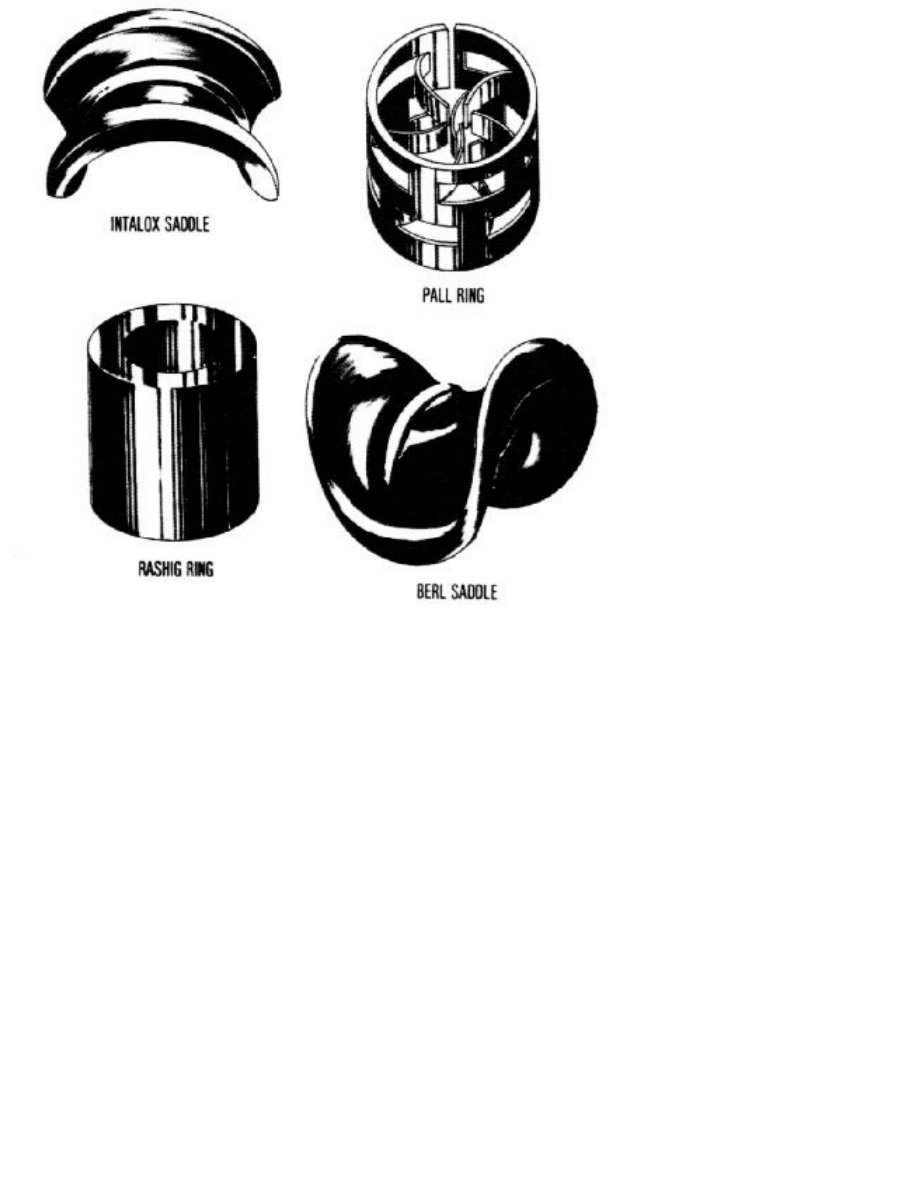
Figure 6. Four common types of packing.
The efficiency of contact between the liquid and the vapor determines a factor known as the "height equivalent
to a theoretical plate" or HETP. A HETP is estimated as follows:
* First, find the actual alcohol separation occurring in a test section of height h.
* Next, use an analysis like Figure 5 to determine the number of equilibrium stages required to give the
separation observed.
* Then, divide height of test section by number of stages.
Marbles are poor packing. They do not spread the liquid coming down the column enough to get an efficient
exposure of liquid-gas interaction. Marble packing, therefore, gives a large HETP value, requiring a tall column.
Also, the inside of the marble is not available for flow, so large diameter columns are required.
Another important consideration in deciding on packing material is how long the packing will hold up in a hot
alcohol solution. Durable packing like stainless steel may last indefinitely but is expensive initially. Thus, cost-
benefit ratio must be considered.
Some general estimates of packing properties are commonly used. The size of the packing should normally be

less than 1/8 of the diameter of the column. The HETP varies with the size of packing, from about 1 1/2 feet (for
1-inch packing) to about 2 1/2 feet (for 2-inch packing). Below 1 inch in size, the HETP usually remains above
1 foot.
The HETP usually gets worse (larger) if the flow is either too high or too low. If flexibility in operation rate is
desired, a packing should be chosen that has a low HETP over a large range of flows. The approximate ratio of
the highest to the lowest flow rates which yield good HETP values is known as the "turndown ratio". Pall rings
and Intalox saddles are good in this respect, with turndown ratios above 6.
If we know the HETP, we can estimate the required column length. With an assumed HETP of 1 1/2 feet and an
ideal number of trays in the rectifying section often, we need a rectifying section 15 feet tall. The HETP will
determine the actual number of plates needed; the number should not be doubled.
All of the previous discussion has considered distillation processes in terms of a constant feed of beer of uniform
alcohol content. Such processes can be operated either as a continuous or as a batch procedure.
POT-TYPE DISTILLATION PROCESS
In the pot distillation process, the entire batch of beer is heated to boiling in a large container, and the alcohol-
water vapors are collected and channeled into a distillation column. Such a process will always be a batch
procedure and involves only the use of a rectifying column, since the Stripping is done as the alcohol vapors are
boiled off from the vat. A pot distillation process is illustrated in Figure 7.
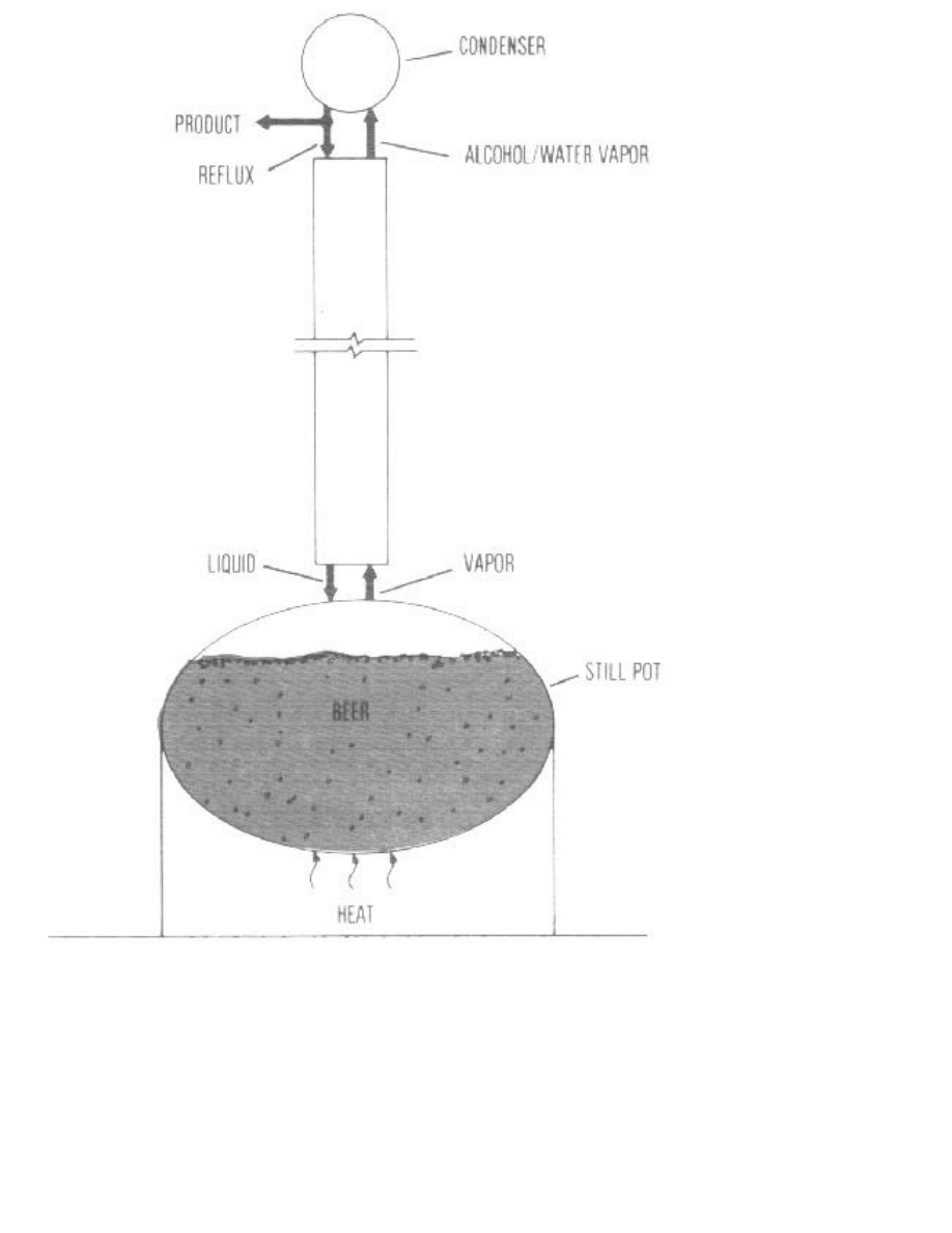
Figure 7. A pot-type batch distillation process.
The process has the characteristic that, as alcohol vapor is boiled off from the beer, the concentration of alcohol
in the beer becomes less and less. As the beer loses its alcohol content, the alcohol product also decreases in
concentration. To prevent this, the reflux ratio must be raised.
Recall that higher reflux ratios usually mean higher proof. Raising the reflux ratio means getting less product
from a given amount of vapor produced, hence a greater energy cost. When almost all the alcohol has been
boiled out of the beer, the process is stopped and the spent stillage (formerly beer) is removed.

The basic advantage of this pot distillation process is its simplicity. It does not require a constant supply of beer,
which is often not available in minimum-labor fuel alcohol processes. It also provides a very simple equipment
system. with cooking, fermentation and boiling for distillation carried out in the same vessel. This procedure
may aid in sterilizing equipment between successive batches, since cooking and fermenting in the same vessel
tends to heat-sterilize. Separation of the spent grain and large solids from the beer prior to heating for distillation
is not necessary, an added advantage.
It is possible to approach a continuous batching operation in a three-vessel, one-column pot system. A batch of
grain would be cooked and fermented every 72 hours, with one batch ready for distillation every 24 hours.
The disadvantage of the pot distillation process and its system simplicity is lower distillation efficiency, because
of the diminishing alcohol concentration in the beer under continuous boiling. Typically, a pot distillation unit
requires about three times as much energy as an equivalent continuous distillation system, based on (by weight)
feed 8 percent, stillage 0.4 percent and product 90 percent. Less stored heat may be used at the end of cooking
when the slurry is rapidly cooled for fermentation; and heat losses during cooking and distillation heating cannot
be minimized as readily as with the constant-feed process. Insulation applied to the pot to conserve heat during
cooking and distillation heating may hinder cooling necessary to fermentation in the summer. Thus, amount of
energy required per gallon of alcohol for the pot distillation process is high.
OTHER DISTILLATION METHODS
Vacuum Distillation
Carrying out distillation using a vacuum (low pressure) allows use of lower temperatures and attains higher
alcohol concentrations. For instance, at 42 mm Hg pressure (about 6 percent of atmospheric pressure (Normal
atmospheric pressure is 760 mm Hg (millimeters of mercury column), equivalent to 30 inches of Hg or 14.7 psi.
Thus, 6 percent of 14.7 psi is approximately 0.88 psi.), the temperature at the bottom of the column need only be
about 35° C (95° F) and the top about 20° C (68° F). This makes it hard to condense the vapor, since there is a
smaller temperature difference between the vapor and the coolant (whether air or water). But this pressure may
be advantageous if heat is supplied at only 35° C Here, waste heat from other machinery or solar heat might be
exploited.
In the vacuum process, the azeotrope (or point where distillation ceases to work) moves toward 100 percent as
the pressure is lowered. At a pressure below 1/10 atmosphere, the azeotrope disappears, enabling distilling all
the way to 100 percent alcohol. However, the difference in volatility (vaporizability) between the water and the
alcohol is still very small, requiring a high reflux ratio (more than 20). The amount of energy used is around
15,000 BTU/pound alcohol produced, which compares to combustion energy of around 11,500 BTU/pound
alcohol.
By holding the condenser near 0° F, a vacuum of around 4 mm Hg could be created. The volatility difference
would be great enough that the energy cost would be about 6000 BTU/pound. The column, however, would
have to be very large to accommodate the large volume of low-pressure vapor. Vacuum distillation appears
uneconomical in commercial applications.
Azeotropic Distillation
This is the term used for the process that produces 100 percent alcohol with the help of an organic solvent and
two additional distillations. It is used by large plants to produce industrial absolute alcohol. In the process, a

solvent, such as pentane or gasoline, is added to the product (alcohol which is not water-free) coming out of the
usual distillation column. This mixture is fed into a distillation column which divides it into a top product (a
distillate of an exact composition determined by the solvent) and a bottom product, which can be controlled to
produce pure alcohol by adjusting the amount of solvent added. The distillate of this column is fed to a third
column, which distills out the solvent, leaving as the bottom product a mixture of just alcohol and water. This
bottom product is returned to the first alcohol-water column.
Ideally, no solvent is added to the system once it's working, because it is recycled and never gets out. This
process is obviously more complicated than the usual distillation system and requires an expert to design.
Adsorption
There are several other methods of producing 100 percent alcohol under development that look promising. One
adsorption process uses a final column packed with organic material, such as finely ground, very dry cornmeal.
Cornmeal is a stable and inexpensive (5-10 cents per pound) selective absorbent of water from ethanol/water
vapor. Laboratory results show that the adsorption of water from ethanol by cornmeal gives an anhydrous (water-
free) product, starting from 190 proof vapors from a distillation column. The process uses two parallel columns
packed with cornmeal or other organic materials, with one column used for adsorption, while the other is being
regenerated (by forcing a hot inert gas through the organic bed to evaporate the water absorbed). The
combustion energy of the ethanol product can exceed the energy needed to carry out the dehydration by a factor
of 10.
This process may have special advantages for use in small scale plants. Further development on the practical
aspects of using this technology is not discussed here.
COLUMN START-UP, OPERATION, AND SHUT-DOWN
Start-Up and Operation
In a continuous flow column, the first step of start-up is to turn on the cooling fluid to the condenser, so that
when the heat is applied later there will be no danger of pressure build-up. Then, if direct steam is used instead
of a reboiler, the steam can be turned on to flush out the air in the system. This is similar to purging a steam
heating system in a house.
If direct steam is not being used, water should be fed into the column at the feed point. This water will run down
to the reboiler and provide steam. Once the air has been sufficiently diluted with steam, there is no possibility of
explosive mixtures being present. However, it is best to force practically all the air out of the system and
through the condenser, so it won't interfere with alcohol separation and heat transfer in the condenser.
Once the system has been purged of air, the reflux ratio can be set and the beer flow started. After sufficient
time (depending on column size, flow rate, etc.-usually several hours), alcohol will spread throughout the
column according to the design. The product will not attain the desired concentration until this distribution
balance is reached. It can be recycled back into the beer tank until this occurs. Or, a quicker method is to reflux
everything until the desired composition is reached, setting the reflux ratio to continue this concentration. The
amount of time in either case depends on column size but usually runs several hours.
If a continuous flow column is used to process batches of beer, be sure the column is small enough that the start-
up time will be relatively small compared to the total run time. Short run times are undesirable, because of the

long start-up, shut-down and cleaning time involved.
Planning the reflux flow and control system is an important factor in product quality control and process
management. One design uses a condensate reservoir, with the reflux rate controlled by a variable-speed pump
drawing from the reservoir. Another design has a gravity flow of reflux from the reservoir, regulated by an
automatic or manual valve. The reservoir may be designed with an overflow into the product line to maintain a
constant pressure on the gravity reflux feed.
A sufficient liquid level in a reboiler used to supply steam to the column is important from a performance and
safety standpoint. The reboiler is under a slight pressure and therefore must be a pressure vessel. It usually has a
gasketed and bolted lid. Welded steam outlet and stillage return lines connect the reboiler to the column. The
liquid return enters the reboiler below the desired liquid level. The outflow of bottoms can be controlled by
regulating the back-pressure in the bottoms line, in turn controlling the level of liquid in the pot. The pot must be
designed so it can be completely drained to ease clean-out.
In a batch system using pot-type distillation, the usual procedure is to start the condenser cooling fluid, and then
turn on the heat below the vat or boiler containing the beer. An outlet must be provided for air escape. (See
previous discussion concerning how to obtain the desired product quality.)
Shut-Down
During shut-down of a continuous system, the first step is to shut off the feed and divert the product. This keeps
low-quality alcohol produced during shut-down from entering the product st&rage tank. The alcohol remaining
in the column can then be distilled out and added to the next batch of beer. A complete sequence is as follows:
1.Turn off feed and steam entering the reboiler.
2.Shut off heat.
3.Increase reflux to 100 percent (no product output).
4.Wait until condenser temperature has cooled to below 100°F.
5.Open vent to the column.
6.Drain column out of the bottom, leaving the air vent at the top open. (Caution: bottoms liquid may be
very hot.)
7.Turn off condenser cooling water.
Because cooling water for the condenser will be needed throughout shut-down, it is the last flow to be stopped.
The exact order in the above steps is not critical, since steps 1-3 are performed in rapid sequence. The important
point is not to vent the column until it has cooled down, to avoid loosing a lot of alcohol vapor which might
burn, smell or explode.
In a pot system, the shut-down consists of turning off the heat and allowing air to enter as the vapors condense.
It may be possible to catch the liquid draining from the column, so that the alcohol it contains won't be lost with
the stillage. The material will initially be very hot, requiring caution in collection and handling.

SOLIDS REMOVAL
Most distillation processes require that the spent grain and all solids be removed from the beer before the feed is
delivered to the column. However, the two "exceptions" discussed below do not require solids removal before
distillation.
One exception is the occasional plate- or tray-type column, designed to pass the mash (beer plus all solids)
through stripper section, using a combination of large holes in the plates and large diameter downcomer pipes
between plates. This helps move the mash (which is like sloppy oatmeal or mush) down the column. Such a
design can be quite effective in stripping the alcohol from the spent grain and solids as well as from the beer; but
it tends to be low in energy efficiency and presents problems in flow uniformity, due to column plugging and
changing solids percentage in the feed. This type column must be designed by an expert. Handling all solids
with the beer may also present some pumping problems along with problems in clean-up.
A second exception is the batch procedure using pot distillation. The beer and mash are simply boiled together
to evaporate the alcohol. The mixture in the pot must be well stirred to prevent the solids from baking onto the
pot surface; and care must be taken to keep the mash from boiling over into the column.
In this process, the liquid condensate from the column returns to the pot or batch tank being boiled. When the
alcohol concentration in what was the beer (now stillage water and distillers grain) reaches a point where further
distillation is not practical, the entire slurry is transferred to a holding tank for processing or feeding. Since most
animal nutritionists do not foresee the feasibility of feeding much of the stillage water, the mash will probably
have to be separated, even if it is fed wet.
Packed columns require a feed that contains very few suspended solids to reduce the chance of plugging,
column contamination and cleaning problems. Most plate- or tray-type columns can handle a small
concentration of suspended solids without plugging or cleaning problems under continuous operation, provided
the heavy solids have been removed. Plate or sieve columns may be easier to clean than packed columns if the
plates are easily removed or accessible.
The heavy solids usually sink to the bottom of the fermentation vat or tank once agitation is stopped. Some of
the beer can then be withdrawn in such a way that none of the remaining heavy solids are withdrawn.
Several farm fuel production installations use a section of "U" trough or round tube auger conveyor, on which a
perforated housing has been rigged on the lower side. The perforated bottom of the, conveyor may also be
covered with a 12-16 mesh screen similar to fly screen. In operation, the auger conveyor is inclined upward at a
15-25 degree angle and the slurry fed into the lower intake end. The auger conveys the stillage over the screen
bottom, with the liquids and fine suspended solids passing through the screen. The larger grain particles are
retained and carried to the top of the incline, where they are discharged into a vehicle or holding chamber. The
auger flight, in scraping the mash across the screen, does a reasonably good job of maintaining flow and clearing
the screen surface. Commercial filters, sieves and screens are also available in stationary, rotary and vibrating
arrangements.
Continuous flow conveyors or extractors that compress the stillage grain to improve beer removal are common
in commercial distilleries. Similar designs sized for small-scale plants are under development. Keep in mind that
separating solids before distillation can result in up to a 20 percent alcohol loss if extraction design is too simple.
INSULATION AND HEAT RECOVERY

A loss of heat along the column causes increased condensation and reduced evaporation. Thus, the amount of
vapor diminishes in the upward part of the column, where the flow of liquid is also less than at the bottom.
Where heat loss occurs, more vapor has to be produced in the reboiler or steam generator, resulting in a loss in
energy efficiency.
In Figure 3, the effect of heat loss is that the bottom line (the rectifier line) curves up and the upper line (the
stripper line) curves down. This means that in the stripper, the "size" or magnitude of the steps considered in the
stepping-off procedure (Figure 5) is decreased, sharply decreasing process efficiency as well.
The distillation column should be well insulated to prevent loss of heat and to protect against burns. Two to
three inches of fiberglass blanket insulation is good. On columns located outdoors because of size and safety,
the insulation blanket will shield the column from increased heat loss due to wind currents. Exposed insulation
blanket may require weather shielding to maintain its performance.
Heat recovery from cooling hot mash for fermentation, from stillage in the column bottoms during distillation
and from heat absorbed in the condenser can be an important source of energy efficiency. A detailed discussion
of heat recovery techniques is outside the scope of this publication; but it is important to note the potential for
energy conservation or heat wastage in a spirits distillation process. The incoming beer feed to the column, for
instance, should be used as the cooling fluid for the condenser as much as possible, in order to reclaim
condensation heat to preheat the beer, thus using and saving energy. However, savings are not as great if
distillers dry solids are produced (spent grain and solids are dried).
The rest of the condensation (over and above what the beer preheating can do) is generally obtained using water.
The water-heating capability of a condenser on a 50-gallon-per-day (2-gallon-per-hour) alcohol plant can
provide 500,000 BTUs per day of heating for buildings. The reclaimed heat available, however, is basically the
amount of heat put into the bottom of the column in the form of steam or reboiler heat. Heat reclamation is cost-
effective only if the heat saved is used efficiently elsewhere as process or space heat. To use waste heat
inefficiently just because it is easily available simply lowers overall system efficiency.
The lines carrying the beer through the condenser for the dual preheating/cooling function slowly accumulate a
protein layer on their inside wall, hampering flow and heat transfer. The protein must be removed periodically
with a caustic (strong base) soda.
Hot stillage water discharged from the base of the stripping column may also be reclaimed and either used to
preheat the beer, used to preheat water for the next cooking cycle or recycled directly info the next batch as the
water for cooking and starch hydrolysis. Up to 1/3 of the stillage water may be recycled as cooking water for the
next batch, provided accumulation of chemical substances from previous fermentations is not a problem. Any of
these waste-heat sources may also be utilized in space or water heating.
A heat exchanger between the partially heated feed coming from the condenser and the very hot stillage from
the bottom of the column can save some energy by further increasing the preheat on the beer feed before it
enters the column.
Be sure to evaluate the cost-benefit ratio when considering use of heat exchangers or heat storage systems.
Process design and choice of equipment should consider energy conservation practices.
FACTORS AFFECTING ENERGY USE AND COLUMN SIZE

This publication does not present details of any particular column design or of input-output conditions.
However, some general relationships between product condition and flow versus column size, number of stages
and energy use can be illustrated. Tables 1-5 were generated by computer analysis to illustrate the basic physical
and performance relationships. They show typical process response and sensitivity as design and operating
factors are varied.
A few principles are:
* Energy usage increases when there is less alcohol in the feed stream or when the product concentration
is raised (Tables 1-3).
* There is a trade-off between energy usage and column length. Columns can usually be made shorter by
using more energy (Table 4).
* The degree to which the feed is preheated also affects the energy usage, as long as preheating is done
"for free" by using the feed as a cooling fluid in the condenser and/or by using heat exchangers (Table 5).
Thus, the best way to operate is to have a good fermentation (high alcohol content in beer), not to try to go much
above 90 percent by weight alcohol in the distillate and to preheat the feed (in the condenser, if not also with a
heat exchanger). In this way, one can produce alcohol for around 1800 BTU/pound (11,000-12,000 BTU/
gallon), which can be burned without further concentration in a slightly modified gasoline engine. However, this
90 percent alcohol will not mix satisfactorily with gasoline to form gasohol.
Assumptions for Table Calculations
Where not otherwise stated in Tables 1-5, the stillage is 0.4 percent, the feed 8 percent and the product 90
percent ethanol by weight. Energy is in BTUs per pound product, while diameter is for 50 gallon-per-hour feed
with a packed column using plastic Intalox saddles for packing.
A 0.4 percent ethanol content in the stillage and an 8 percent ethanol content in the feed calculates as a 5 percent
overall ethanol loss. (If the feed were only 4-6 percent ethanol concentration, the loss ratio will be much higher).
A 5 percent continuous loss would mean a substantial loss of profit. The 0.4 percent loss level should not
necessarily be considered as a desired loss level, but rather as a typical illustration (see Table 3).
In Table 1, the column entitled "reflux ratio" is the external reflux ratio -i.e., the ratio of liquid condensate
returned as reflux to that kept as product. Having chosen this ratio and the concentration of stillage, feed and
product, the ideal number of stages required in the rectifying and stripping sections, as well as the energy, are
then determined.
The diameter is not strictly determined; the diameter given is a recommended value generated by computer. In
practice, a standard-size commercially available column or pipe which is as large or slightly larger than the
listed diameter would be used.
The "energy ratio in/out" column is the ratio of energy required for distillation to energy produced by burning
the product.
Note that as the feed concentration goes up from 1 percent alcohol to 12 percent, the reflux ratio becomes quite
low. This means that the amount of energy required also tails dramatically. This is why it is important to have a

good fermentation and to produce a high concentration of alcohol in the beer.
Table 1. Varying the Feed (product = 90%, bottoms = 0.4%).
Beer Rectifying Stripping Column Energy
feed Reflux column column Energy use diameter ratio
(wt.%) ratio stages stages (BTU/lb.) (in.) in/out
-------------------------------------------------------------------------
1 33.9 7 2 15300 4.3 1.5
2 16.1 7 3 7510 5.0 .73
3 10.1 7 4 4870 5.1 .47
4 7 1 7 5 3580 5.2 .35
5 5.4 7 6 2810 5.2 .27
6 4.6 7 6 2460 5.4 .24
8 3.5 8 5 1980 5.7 .19
9 3 8 6 1760 5.7 .17
10 2.7 8 6 1630 5.8 .16
11 2.5 8 6 1540 6.0 .15
12 2.3 8 6 1450 6.1 .14
-------------------------------------------------------------------------
Table 2 shows that the amount of energy needed increases as the alcohol concentration in the product increases.
But since the energy given by burning is also higher for higher product concentration, the energy-in to energy-
out ratio is rather constant up to about 93 percent. After this point, the ratio increases dramatically because of
the "sway back" in the equilibrium curve discussed in the text (i.e., the reflux ratio has to be much higher). Here
the energy cost is much higher, too. Notice also that the length of the column (number of stages) gets very great
as the desired product concentration approaches the azeotrope (95.6 percent).
Table 2. Varying the Distillate Concentration (feed = 8%, bottoms = 0.4%).
Alcohol Rectifying Stripping Column Energy
product Reflux column column Energy use diameter ratio
(wt.%) ratio stages stages (BTU/lb.) (in.) in/out
--------------------------------------------------------------------
50 .2 2 11 811 4.9 .15
50 4 2 6 946 5.3 .18
60 .7 2 10 1050 5.1 .16
60 1 2 6 1230 5.5 .19
70 1.2 3 10 1230 5.1 .16
70 1.5 3 6 1390 5.4 .18
80 1.8 4 12 1400 5.0 .15
80 2.2 4 7 1590 5.4 .18
85 2.3 5 9 1550 5.2 .16
85 2.7 5 6 1730 5.5 .18
90 2.6 9 11 1580 5.1 .15
90 3 8 7 1760 5.3 .17
90 3.5 8 5 1980 5.7 .19
93 3 18 10 1690 5.1 .16
93 4 14 6 2110 5.7 .20

93 5 13 4 2530 6.3 .24
95 5.5 67 4 2660 6.4 .24
95 6 53 3 2870 6.6 .26
95 7 41 3 3280 7.1 .30
95 8 36 3 3690 7.5 .34
95.5 8.5 90 3 3860 7.7 .35
95.5 12 57 3 5290 9.0 .48
--------------------------------------------------------------------
In Table 3, note that more stages are needed in the bottom section (the stripping section) to get less alcohol in
the bottoms. Again, the effect can also be achieved to an extent by using more energy. Also notice here that the
amount of energy needed per unit of product is constant, given a constant feed concentration, product
concentration and reflux ratio. Thus, no energy is saved by recovering more of the alcohol from the beer; but
one would, of course, save on the raw material of the fermentation.
Table 3. Varying Bottoms Concentration (feed = 8%, product = 90%).
Alcohol
bottoms Alcohol Rectifying Stripping Column Energy
concentration loss Reflux column column Energy use diameter ratio
(wt.%) (wt.%) ratio stages stages (BTU/lb.) (in.) in/out
----------------------------------------------------------------------------------
3 35.3 3 8 3 1760 4.4 .17
2 23.3 3 8 3 1760 4.8 .17
1 11.5 3 8 5 1760 5.1 .17
.5 5.7 3 8 7 1760 5.3 .17
.5 5.7 5 7 3 2640 6.5 .26
.2 2.3 3 8 9 1760 5.4 .17
.2 2.3 5 7 5 2640 6.6 .26
.1 1.1 3 8 12 1760 5.4 .17
----------------------------------------------------------------------------------
The alcohol loss levels (column 2) for various levels of bottoms concentration (even at a bottoms concentration
of only 0.1 percent) is over 1 percent of the total. Adding only three stages from 9 to 12 in the stripping column
cut the alcohol loss more than half. Losses in the bottoms are very important from a profit standpoint. The key
question is, "How much can I afford to lose?"
Table 4 gives a larger range of reflux ratios for the same feed, product and bottoms. Note again the trade-off
between energy Usage and column length. We can get the same results by using a small reflux ratio (low
energy) and a column of 26 total stages, or with a high reflux ratio (high energy) and only nine column stages.
Table 4. Varying Reflux Ratio (bottoms = O.4%, feed = 8%, product = 90%).
Rectifying Stripping Column Energy
Reflux column column Energy use diameter ratio
ratio stages stages (BTU/lb.) (in.) in/out
----------------------------------------------------------------
2.5 10 16 1540 5.0 .15

3 8 7 1760 5.3 .17
3.5 8 5 1980 5.7 .19
4 7 5 2200 6.0 .21
5 7 4 2630 6.5 .26
6 7 3 3070 7.1 .30
8 6 3 3950 8.0 .38
10 6 3 4830 8.9 .47
----------------------------------------------------------------
Table 5 shows the effects of preheating the feed on energy requirements. The 86° F feed represents un-preheated
beer. A temperature of 173° F is approached by preheating in the condenser only, while 198° F (the boiling
point of 8 percent alcohol) can also be reached by using a heat exchanger with the stillage. A perfect heat
exchanger could actually vaporize about 1.4 percent of the beer, leading to the lowest energy usage. Small
changes in the temperature of the feed can cause rather large changes in the reflux ratio needed, and hence in the
energy cost.
Table 5. Varying the Feed Conditions (bottoms = 0.4% feed = 8%, product = 90%).
Rectifying Stripping Column Energy
Reflux column column Energy use diameter ratio
State of feed ratio stages stages (BTU/lb.) (in.) in/out
-------------------------------------------------------------------------
2% vaporized 2.9 9 12 1490 4.9 .15
2% vaporized 3 9 10 1540 5.0 .15
2% vaporized 3.5 8 7 1760 5.3 .17
198 F 2.5 10 16 1540 5.0 .15
198 F 2.6 9 11 1580 5.1 .15
198 F 2.9 8 8 1710 5.3 .17
198 F 3.2 8 6 1840 5.5 .18
173 F 2.9 8 6 1930 5.6 .19
173 F 2.9 8 6 1930 5.6 .19
86 F 1.4 12 7 2470 6.3 .24
86 F 1.9 9 5 2690 6.6 .26
-------------------------------------------------------------------------
FUEL FOR PROCESS HEAT
Ideally, fuel sources for cooking and distilling fuel alcohol would come from solid fuels, such as coal, wood and
crop residues. Such practice would minimize the amount of high-quality liquid and gaseous fuels consumed for
heating and increase the total quantity of liquid fuels available. Alternative fuels include: natural and LP gas and
fuel oil; alcohol product: mined solid fuels (coal, peat, anthracite); crop and forest residues, farm and forest fuel
crops and combustible wastes: methane gas produced from animal wastes and biomass; and solar radiation.
Liquid and gaseous fuels have the advantage of clean burning and easy combustion control. They are high in
quality, portable, expensive and storable with high value alternative uses.
Solid fuels can save on the amount of premium liquid and gaseous fuels that must be consumed, but present air

pollution and process control problems that are not easily solved. Harvest, handling and conversion technology
for crop, forest and other cellulosic materials needs further development.
Methane gas from animal and industrial wastes and biomass presents an interesting possibility as a source of
process fuel, but requires a major investment in technology and production plant to produce.
Solar heating requires concentrating collectors (e.g., parabolic) to produce the likely process temperatures and
overall performance needed. It also limits operation to daytime hours and sunny days or requires a way of
storing energy at high temperatures.
In planning any fuel alcohol production plant, whether an individual farm unit, a small cooperative project or a
large community or industrial fuel alcohol plant, consideration must be given to the short-and long-run
availability and price of alternative fuels. The implications in plant design and operation, if solid fuels are used
or needed in the future, must be seriously evaluated.
The alcohol product itself may be used to fuel the process. However, this basically spends one unit of high-
quality liquid fuel to save one unit of another type of fuel, making the unit of alcohol fuel unavailable for
replacing imported or domestic oil.
SAFETY AND CONTROLS
Alcohol distillation involves some dangers besides the ordinary risks of large, complex equipment.
Explosion or Burning
The first danger is that of explosion or burning of the alcohol. Most farmers immediately recognize the potential
explosion or fire dangers of distilling a petroleum fraction to produce gasoline. Alcohol and gasoline fuels share
these common risks-a primary reason they are such excellent fuel sources for spark ignition engines, which
actually use a controlled explosion to produce power Table 6 lists some characteristics of both fuels.
Table 6. Characteristics of Ethanol and Gasoline.
1
Characteristic Ethanol Gasoline
--------------------------------------------------------
Flash point 55 F -44 F
Ignition temperature 689 F 536 F
Vapor flammability limit 3.3-19 1.4-7 6
(% by volume)
Specific gravity 0.8 0.8
(Water equals 1)
Vapor density 1.6 3-4
(Air equals 1)
Boiling point 172 F 100-400 F

--------------------------------------------------------
1 "Suggested Underwriting Guidelines for Ethanol Production",
Special Release, October, 1980
In accordance with the National Fire Protection Association's pamphlet #30, "Flammable and Combustible
Liquid Code"(Pamphlet #30 "Flammable and Combustible Liquid Code", National Fire Protection Association.
60 Batterymarch Street. Boston. MA 02110.US), any liquid with a flash point (the lowest temperature at which
that fuel will give off flammable vapors) less than 73° F and a boiling point 100° F or above is classified as a
Class I-B flammable liquid. The ignition temperature (in the table) is the lowest temperature that vapors will
ignite. Since both ethanol and gasoline are classified as Class I-B flammable liquids, the same safety
considerations given to the production, storage and handling of gasoline must also be used with ethanol.
Alcohol vapor is explosive when mixed with air in amounts ranging from 3-19 percent by volume, at room
temperature and atmospheric pressure. Gasoline vapor is explosive when mixed with air in the range of from 1.4-
7.6 percent by volume for the same temperature and pressure conditions. Both alcohol and gasoline vapors are
heavier than air, which may add to their accumulation in enclosed areas or in low-lying ground depressions
around or down stream from the vapor source.
Handling such volatile fuels must always be cautious and planned. Gasoline is one suggested additive that can
be applied to ethyl alcohol fuels to denature the alcohol and render it unfit for human consumption. Be sure to
treat both products with equal caution when combining them. Adding alcohol to diesel fuel to make "diesohol"
increases the volatility of diesel fuel, requiring added safety precautions.
The basic precautions for handling alcohol fuels and alcohol-gasoline or alcohol-diesel blends are:
1. Never smoke anywhere in or around the buildings or process equipment.
2. Have interconnected electrical grounding of all process equipment and storage components to
minimize the risk of a spark from static electricity or a ground fault occurring in the presence of an
explosive mixture.
3. Install adequate gauges and controls to permit rapid monitoring and control of the process.
A distillation column contains no air in normal operation, so there is no danger of the vapor or liquid inside
catching fire or exploding. But air is present during column start-up and shut-down. As long as you maintain no
possibility of a spark or source of ignition, the danger is minimal. The way to do so is to purge the column of
any presence of air by starting the column on water without any alcohol. This replaces the air with steam before
the alcohol is introduced.
Another precaution is to guard against leaks, which would allow alcohol vapor and air to mix in the column.
Leaks are most likely with vacuum distillation, whereas the slight positive pressure normally accompanying
"atmospheric" distillation will keep air from leaking into the still. Keeping air out of the column also makes the
column and the condenser more efficient.
Blow-Out of Components
A second danger is a blow-out of components due to pressure build-up. Source of the pressure is the steam
produced by constant heating of the reboiler, or that injected from a separate steam generator. Pressure builds up
if too much resistance occurs from the flow of gas up the column or the flow of product out of the condenser.

The former can happen if: (1) the column is too small for the amount of liquid or gas being put through it, (2) a
flow blockage develops due to an accumulation of solids in the column, or (3) a failure of a packing or a plate
assembly exists. Be sure that there is an outlet to the atmosphere somewhere downstream from the condenser,
such as in the storage tank for the product.
To avert high-pressure blow-outs of plumbing and equipment, pressure gauges and pop-off valves should be
installed in the following places: (1) in the condenser to sense product pressure, (2) near the base of the stripping
and rectifying column sections to sense internal column pressure, and (3) in the reboiler steam chamber or the
steam injector nozzle to sense steam pressure being applied.
All pop-off or pressure relief valves should be placed in such a way that discharge is directed away from any
place where an operator or a visitor might be sprayed. This discharge should be vented out-of-doors. Test all
pressure relief valves periodically to make sure that they are operable and set for the correct pressure.
The system should also be equipped with automatic shut-off controls on the heat going to the reboiler or the
steam to the injector. If the temperature at the bottom of the column reaches more than a few degrees above the
boiling point of water (212° F). the shut-off controls will activate. This happens if either the pressure in the
column gets too high or the reboiler runs nearly dry.
A good control concept and good-quality control equipment go hand in hand with top process performance and
safety. When things work right, the safety risk is always at the minimum. Remember that a continuously
operating distillation process must simultaneously and continuously monitor and regulate: (1) beer feed rate and
temperature, (2) column pressure and temperature (for both the stripping and the rectifying sections), (3) reflux-
to-product flow rate to control the column discharge temperature and alcohol vapor concentration, and (4) heat
application to the reboiler or steam flow from the injector.
Ideally, each control function can modulate the flow of fluid, vapor or energy and maintain a continuous balance
of the process. Installing sight gauges for water level, pressure and temperature will provide added visual
information to evaluate system performance.
WHERE DO I GO FROM HERE?
The discussion of alcohol distillation processes presented in this publication is not intended to teach process
design, but rather understanding. The following references should be useful in further developing that
understanding. If a decision is made to pursue the design and development of a small-scale alcohol production
and distillation system, competent technical consultant(s) should be employed.
REFERENCES*
1.Westby, Carl A. and W. D. Gibbons, "Farm-Scale Production of Fuel Ethanol and Wet Grain from
Corn in a Batch Process", Biotechnology and Bioengineering, vol. 24, July 1982, pp. 1681-1699.
2.Hong, J., M. Voloch, M. R. Ladisch, and G. T. Tsao. "Adsorption of Ethanol-Water Mixtures by
Biomass Materials," Biotechnology and Bioengineering, vol. 24, September 1981, pp. 725-730.
3.Ladisch, Michael R. and Karen Dyck. "Dehydration of Ethanol: New Approach Gives Positive Energy
Balance," Science, vol. 205, no. 4409, August 1979, pp. 898-900.

4.Bergland, Gary R. and John G. Richardson. "Design for a Small-Scale Fuel Alcohol Plant," Chemical
Engineering Progress, August 1982, pp. 60-67.
5.Fuel from Farms, A Guide to Small-Scale Ethanol Production. U.S. Department of Agriculture and
Office of Alcohol Fuels, U.S. Department of Energy, Washington, D.C., May 1982, 163 pp.
6.Ethanol Production and Utilization for Fuel. Cooperative Extension Service, University of Nebraska,
Lincoln, NE, February 1980, 85 pp.
7."Feed and Fuel from Ethanol Production." From Proceedings of the Feed and Fuel from Ethanol
Production Symposium, Philadelphia, PA, NRAES-17. Cooperative Extension Service, North- east
Regional Agricultural Engineering Service, Cornell University, Ithaca, NY, September 1981, 101 pp.
8.Selected Bibliography on Alcohol Fuels (1901 through November 1981). U.S. Department of
Agriculture and Office of Alcohol Fuels, U.S. Department of Energy, Washington, D.C., March 1982,
460 pp.
9."Alcohol and Vegetable Oil as Alternative Fuels." Proceedings of Regional Workshops. Northern
Agricultural Energy Center, Technology Transfer Program. 181 SN. University, St., Peoria, IL, April
1981, 337 pp.
10. Ethanol Fuels Reference Guide. Superintendent of Documents. U.S. Government Printing Office,
Washington, D.C., October 1982, 240 pp.
11. Small-Scale Fuel Alcohol Production. U.S. Department of Agriculture, Washington, D.C., March
1980, 232 pp.
*These publications are generally only available at libraries associated with Land Grant universities (usually
your agricultural university), community and junior colleges interested in agriculture and alternative energy,
and organizations involved in research on alcohol fuels and alternative energy. Several of the titles are
accessible for reading only (not check out) from a small special alcohol fuel reference library supplied to the
county Extension offices in Indiana.
For more information, contact Dirk Maier, Agricultural and Biological Engineering, phone: 317-494-1175 or e-
mail: maier@ecn.purdue.edu
New 4/84
Cooperative Extension work in Agriculture and Home Economics, state of Indiana, Purdue University, and U.S.
Department of Agriculture cooperating; HA. Wadsworth, Director, West Lafayette. IN. Issued in furtherance of
the acts of May 8 and June 30, 1914. Purdue University Cooperative Extension Service is an equal opportunity/
equal access institution.
Document Outline
- purdue.edu
Wyszukiwarka
Podobne podstrony:
więcej podobnych podstron