MODFLOW-2000, THE U.S. GEOLOGICAL SURVEY
MODULAR GROUND-WATER MODEL—DOCUMENTATION
OF PACKAGES FOR SIMULATING EVAPOTRANSPIRATION
WITH A SEGMENTED FUNCTION (ETS1) AND DRAINS WITH
RETURN FLOW (DRT1)
U.S. Department of the Interior
U.S. Geological Survey
Open-File Report 00–466
Prepared in cooperation with the Colorado Water Conservation Board
and the Colorado Division of Water Resources

MODFLOW-2000, THE U.S. GEOLOGICAL SURVEY
MODULAR GROUND-WATER MODEL—DOCUMENTATION
OF PACKAGES FOR SIMULATING EVAPOTRANSPIRATION
WITH A SEGMENTED FUNCTION (ETS1) AND DRAINS
WITH RETURN FLOW (DRT1)
By
Edward R. Banta
Denver, Colorado
2000
U.S. GEOLOGICAL SURVEY
Open-File Report 00–466
Prepared in cooperation with the Colorado Water Conservation Board
and the Colorado Division of Water Resources

The use of firm, trade, and brand names in this report is for identification purposes only and does
not constitute endorsement by the U.S. Geological Survey.
For additional information write to:
Copies of this report can be
U.S. Geological Survey
Information Services
Box 25286
Federal Center
Denver, CO 80225
purchased from
:
District Chief
U.S. Geological Survey
Box 25046, Mail Stop 415
Denver Federal Center
Denver, CO 80225–0046
U.S. DEPARTMENT OF THE INTERIOR
BRUCE BABBITT,
Secretary
U.S. GEOLOGICAL SURVEY
Charles G. Groat,
Director

Preface
III
PREFACE
This report documents two computer-program packages designed to work with the U.S. Geological Survey
modular ground-water-flow model, MODFLOW-2000. The packages are designed to simulate (1) evapotranspira-
tion using a segmented-line relation of evapotranspiration rate to hydraulic head, and (2) drainage of water from a
ground-water system, with an option to simulate return flow of some of the drained water.
The code for the packages is contained in this report and is included in MODFLOW-2000, which is available
for downloading over the Internet from a U.S. Geological Survey software repository. The repository is accessible
on the World Wide Web from the U.S. Geological Survey Water Resources web page at the Universal Resource
Locator (URL) http://water.usgs.gov/. The URL for the software repository is http://water.usgs.gov/software/. If
revisions are made to the packages, the revised code will be made available from the software repository.

Contents
V
CONTENTS
PREFACE .............................................................................................................................................................................. III
ABSTRACT...........................................................................................................................................................................
1
INTRODUCTION .................................................................................................................................................................
1
EVAPOTRANSPIRATION SEGMENTS PACKAGE ..........................................................................................................
2
Conceptualization of Evapotranspiration Segments ....................................................................................................
3
Input Instructions for the Evapotranspiration Segments Package ...............................................................................
5
Explanation of Variables Read by the Evapotranspiration Segments Package............................................................
7
ETS1 Example Problem ..............................................................................................................................................
9
Module Documentation for the Evapotranspiration Segments Package...................................................................... 10
Module GWF1ETS1AL..................................................................................................................................... 11
Module GWF1ETS1RQ .................................................................................................................................... 14
Module GWF1ETS1RP ..................................................................................................................................... 15
Module GWF1ETS1FM .................................................................................................................................... 18
Module GWF1ETS1BD .................................................................................................................................... 22
Module SEN1ETS1FM ..................................................................................................................................... 26
DRAIN RETURN PACKAGE............................................................................................................................................... 30
Conceptualization of Drains with Return Flow ........................................................................................................... 31
Input Instructions for the Drain Return Package ......................................................................................................... 32
Explanation of Variables Read by the Drain Return Package ..................................................................................... 33
Flow Observations Using the Drain Return Package................................................................................................... 35
Input Instructions for Flow Observations .......................................................................................................... 35
Explanation of Variables for Flow Observations ............................................................................................... 35
DRT1 Example Problem.............................................................................................................................................. 37
Module Documentation for the Drain Return Package ............................................................................................... 39
Module GWF1DRT1AL .................................................................................................................................... 40
Module GWF1DRT1RQ.................................................................................................................................... 42
Module GWF1DRT1RP .................................................................................................................................... 44
Module GWF1DRT1FM.................................................................................................................................... 46
Module GWF1DRT1BD.................................................................................................................................... 48
Module SGWF1DRT1LR .................................................................................................................................. 53
Module SGWF1DRT1LS .................................................................................................................................. 58
Module OBS1DRT1AL ..................................................................................................................................... 62
Module OBS1DRT1RP...................................................................................................................................... 64
Module OBS1DRT1FM..................................................................................................................................... 70
Module OBS1DRT1DR..................................................................................................................................... 74
Module SOBS1DRT1OH .................................................................................................................................. 78
Module SOBS1DRT1QC................................................................................................................................... 83
Module SEN1DRT1FM..................................................................................................................................... 86
PARAMETER-ESTIMATION EXAMPLE PROBLEM....................................................................................................... 88
MODFLOW-2000 MODIFICATIONS NEEDED TO USE ETS1 AND DRT1 ................................................................... 89
File mf2k.f ................................................................................................................................................................... 90
File obs1bas6.f ............................................................................................................................................................. 92
File sen1bas6.f ............................................................................................................................................................. 93
File pes1bas6.f ............................................................................................................................................................. 93
File pes1gau1.f............................................................................................................................................................. 93
REFERENCES ...................................................................................................................................................................... 94
APPENDIX A—Input and Output Files for the ETS1 Example Problem ............................................................................ 97
APPENDIX B—Input and Output Files for the DRT1 Example Problem............................................................................ 105
APPENDIX C—Input and Output Files for the Parameter-Estimation Example Problem................................................... 111

VI
Contents
FIGURES
1.
Diagram showing conceptual surfaces used in simulating evapotranspiration...........................................................
3
2.
Graph showing volumetric evapotranspiration rate, Q
ET
, as a function of head for a situation
in which the function in the variable interval is defined using three segments ..........................................................
4
3.
Diagram showing hypothetical field situation showing cells from which evapotranspiration can
be extracted under the two options available in the ETS1 Package............................................................................
6
4.
Graph showing segmented relation of volumetric evapotranspiration rate to head for one cell
in the ETS1 example problem ....................................................................................................................................
9
5.
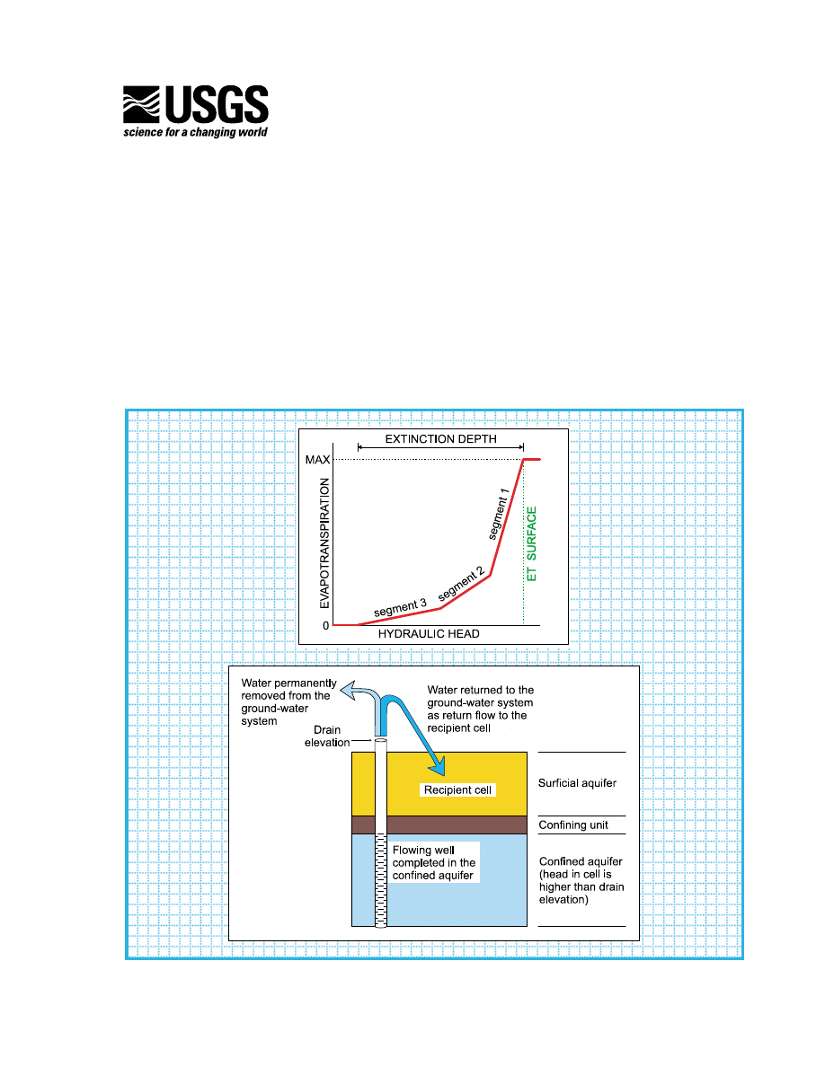
Diagram showing conceptual model of the use of the DRT1 Package to simulate the return
flow of a portion of discharge from a flowing well..................................................................................................... 32
6.
Diagram showing location of features simulated in the DRT1 example problem ...................................................... 38
TABLE
1.
Parameters defined by parameter-estimation example problem and starting, estimated, and
true parameter values .............................................................................................................................................. 89
CONVERSION FACTORS AND ABBREVIATIONS
Other abbreviations, terms, and symbols used in this report:
length (L)
time (T)
Multiply
By
To obtain
foot (ft)
0.3048
meter
foot per day (ft/d)
0.3048
meter per day
square foot per day (ft
2
/d)
0.09290
square meter per day

Introduction
1
ABSTRACT
Two new packages for the U.S. Geological Survey modular finite-difference ground-water-flow
model MODFLOW-2000 are documented. The new packages provide flexibility in simulating evapo-
transpiration and drain features not provided by the MODFLOW-2000 Evapotranspiration (EVT) and
Drain (DRN) Packages. The report describes conceptualization of the packages, input instructions, list-
ings and explanations of the source code, and example simulations.
The new Evapotranspiration Segments (ETS1) Package allows simulation of evapotranspiration
with a user-defined relation between evapotranspiration rate and hydraulic head. This capability
provides a degree of flexibility not supported by the EVT Package, which has been available in
MODFLOW since its initial release. In the ETS1 Package, the relation of evapotranspiration rate to
hydraulic head is conceptualized as a segmented line between an evaporation surface, defined as the
elevation where the evapotranspiration rate reaches a maximum, and an elevation located at an extinc-
tion depth below the evaporation surface, where the evapotranspiration rate reaches zero. The user
supplies input to define as many intermediate segment endpoints as desired to define the relation of
evapotranspiration rate to head between these two elevations. The EVT Package, in contrast, simulates
evapotranspiration with a single linear function.
The new Drain Return (DRT1) Package can be used to simulate the return flow of water
discharged from a drain feature back into the ground-water system. The DRN Package, which has been
available in MODFLOW since its initial release, does not have the capability to simulate return of flow.
If the return-flow option of the DRT1 Package is selected, for each cell designated as a drain-return cell,
the user has the option of specifying a proportion of the water simulated as leaving the ground-water
system through the drain feature that is to be simulated as returning simultaneously to one other cell in
the model.
INTRODUCTION
The U.S. Geological Survey (USGS) modular three-dimensional finite-difference ground-water-
flow model (McDonald and Harbaugh, 1988; Harbaugh and McDonald, 1996a, 1996b), commonly known as
MODFLOW, has included support for simulating evapotranspiration and flow to drains since its initial release.
In the modular design of MODFLOW, such stresses to a ground-water system are simulated by using groups
of subroutines called packages. In previous versions of MODFLOW, evapotranspiration can be simulated using
the Evapotranspiration (EVT) Package, and flow to drain features—for example, springs or agricultural
drains—can be simulated using the Drain (DRN) Package. However, the conceptual models underlying these
capabilities are not sufficiently complex to simulate certain field situations. The U.S. Geological Survey, in coop-
eration with the Colorado Water Conservation Board and the Colorado Division of Water Resources, developed
two new MODFLOW-2000 packages to allow simulation of more complex field situations.
MODFLOW-2000, The U.S. Geological Survey Modular
Ground-Water Model—Documentation of Packages for
Simulating Evapotranspiration with a Segmented Function
(ETS1) and Drains with Return Flow (DRT1)
By Edward R. Banta

2
MODFLOW-2000—Documentation of Packages for Simulating Evapotranspiration with a
Segmented Function (ETS1) and Drains with Return Flow (DRT1)
This report documents two new MODFLOW packages. The Evapotranspiration Segments (ETS1) Package
allows the user to specify a complex relation between evapotranspiration rate and hydraulic head. The Drain
Return (DRT1) Package allows the user to specify that a certain proportion of the simulated flow out of the
ground-water system at a drain cell be returned as simulated flow into any cell in the model. The report presents
the conceptualization for each package, input instructions, listings and explanations of the source code, and
example simulations.
The modular design of MODFLOW was enhanced with the release of MODFLOW-2000 by the addition of
the concept of processes (Harbaugh and others, 2000). In MODFLOW-2000, the simulation of ground-water flow,
which earlier versions of MODFLOW performed, is handled by the Ground-Water Flow Process. In addition,
MODFLOW-2000 includes the Observation, Sensitivity, and Parameter-Estimation Processes (Hill and others,
2000). The ETS1 Package includes support for the Ground-Water Flow, Sensitivity, and Parameter-Estimation
Processes. The DRT1 Package includes support for the Ground-Water Flow, Observation, Sensitivity, and
Parameter-Estimation Processes. This report assumes the user is familiar with MODFLOW-2000 and its Ground-
Water Flow, Observation, Sensitivity, and Parameter-Estimation Processes. Familiarity with the GLOBAL and
LIST output files (Harbaugh and others, 2000) also is assumed.
The source code for the subroutines of the ETS1 and DRT1 Packages generally conforms to FORTRAN 77
(American National Standards Institute, 1978), with the exception that some symbolic names exceed the 6-character
length limit. In addition, MODFLOW-2000 uses Fortran 90 (American National Standards Institute, 1992) state-
ments for dynamic memory allocation. The source code can be converted to use only static memory allocation by
following the instructions in Appendix B of Hill and others (2000). The program can be used on any computer or
operating system for which an appropriate Fortran compiler is available.
EVAPOTRANSPIRATION SEGMENTS PACKAGE
Evapotranspiration can account for a substantial fraction of the water budget for a ground-water system.
When modeling flow in a ground-water system where a large fraction of the water budget is lost through evapo-
transpiration, the method by which evapotranspiration is simulated can affect calculated hydraulic heads, and
thus interpretations regarding the system dynamics. The Evapotranspiration (EVT) Package (McDonald and
Harbaugh, 1988) provides a useful method for simulating evapotranspiration that may be based on a more simpli-
fied conceptual model of evapotranspiration than is warranted by knowledge of actual field conditions. The
method of simulating evapotranspiration used in the ETS1 Package documented in this report provides the flexi-
bility to represent a complex relation of evapotranspiration rate to hydraulic head.
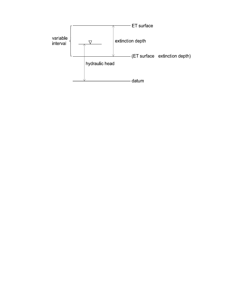
In the EVT Package, which has always been in MODFLOW, the evapotranspiration rate for a particular cell
is calculated based on the simulated hydraulic head in the cell, an “ET surface,” an “extinction depth” (fig. 1), and
a maximum evapotranspiration flux rate. If the elevation of the calculated hydraulic head (head) in the cell is at or
above the ET surface, the evapotranspiration rate is the maximum evapotranspiration rate. If the depth of the head
below the ET surface equals or exceeds the extinction depth, the evapotranspiration rate is zero. When the head is
below the ET surface but the depth of the head below the surface is less than the extinction depth, the evapotrans-
piration rate is variable and depends on the depth of the head below the ET surface. This interval, between the ET
surface and the elevation defined as the ET surface minus the extinction depth, is referred to as the “variable
interval” in this report. In the EVT Package, when the head is in the variable interval, the evapotranspiration rate
is a simple linear function of depth of the head below the ET surface, such that the evapotranspiration rate is the
maximum evapotranspiration rate when the depth is zero, and the evapotranspiration rate is zero when the depth
equals the extinction depth. This relation is defined by equation (1):
(1)
Q
Q
ETM
1
D
X
----
–
×
=
Evapotranspiration Segments Package
3
where
Q
is the volumetric evapotranspiration rate for the cell (L
3
/T),
Q
ETM
is the maximum evapotranspiration flux rate times the area of the cell (L
3
/T),
D
is the depth of the head below the ET surface (L), and
X
is the extinction depth (L).
The ETS1 Package differs from the EVT Package in that the ETS1 Package allows the user to specify a
segmented function for the relation of evapotranspiration rate to depth of head below the ET surface in the vari-
able interval (fig. 1). The user can specify as many segments as desired to approximate a curve or other type of
relation.
Conceptualization of Evapotranspiration Segments
In the ETS1 Package, the functional relation of evapotranspiration rate to head is conceptualized as a
segmented line in the variable interval. The segments that determine the shape of the function in the variable
interval are defined by intermediate points where adjacent segments join. The ends of the segments at the top
and bottom of the variable interval are defined by the ET surface, the maximum evapotranspiration rate, and the
extinction depth. The number of intermediate points that must be defined is one less than the number of segments
in the variable interval. For each intermediate point, two values, PXDP and PETM, are entered to define the point.
PXDP is a proportion (between zero and one) of the extinction depth, and PETM is a proportion of the maximum
evapotranspiration rate. PXDP is 0.0 at the ET surface and is 1.0 at the bottom of the variable interval. PETM
is 1.0 at the ET surface and is 0.0 at the bottom of the variable interval. Segments are numbered such that
segment one is the segment with its upper endpoint at the ET surface, and segment numbers increase downward.
The relation of evapotranspiration rate to head is defined over the model grid by a series of two-dimensional
arrays; therefore, PXDP and PETM also are specified as arrays.
When MODFLOW-2000 solves for heads, the ETS1 Package calculates an evapotranspiration rate for each
cell where evapotranspiration is simulated by first determining which segment should be used based on the head,
then calculating the evapotranspiration rate by interpolation. The interpolated evapotranspiration rate for a cell is
defined by equation (2):
(2)
Q
PETM
n
1
–
Q
ETM
PETM
n
1
–
PETM
n
–
(
)
PXDP
n
PXDP
n
1
–
–
(
)
--------------------------------------------------------
Q
ETM
X
--------------
D
PXDP
n
1
–
X
×
–
(
)
×
×
–
×
=
Figure 1.-- Conceptual surfaces used in simulating evapotranspiration. In the ETS1
Package, segments are defined in the variable interval.
_
4
MODFLOW-2000—Documentation of Packages for Simulating Evapotranspiration with a
Segmented Function (ETS1) and Drains with Return Flow (DRT1)
where n is the segment number of the applicable segment and refers to the point at the bottom of the segment,
and other symbols are as defined above or for equation (1). When n is 1, n–1 refers to the upper end of the first
segment, where PXDP = 0.0 and PETM = 1.0. Similarly, for the last segment, n is the total number of segments,
PXDP
n
= 1.0, and PETM
n
= 0.0. The maximum evapotranspiration flux rate may be defined in program input
either directly, by entering an array of numeric values, or indirectly, by using parameters. The concept of using
parameters to define model input is described by Harbaugh and others (2000). When a parameter is used to define
the maximum evapotranspiration flux rate, Q
ETM
is the product of the parameter value, the multiplier from the
multiplier array (if defined for the parameter), and the cell area. As with any head-dependent flow boundary, the
head used in the calculation, in this case the calculation of D, is the head that resulted from the previous solver
iteration. For this reason, to obtain an accurate head solution, solver input must specify that an iterative method be
used.
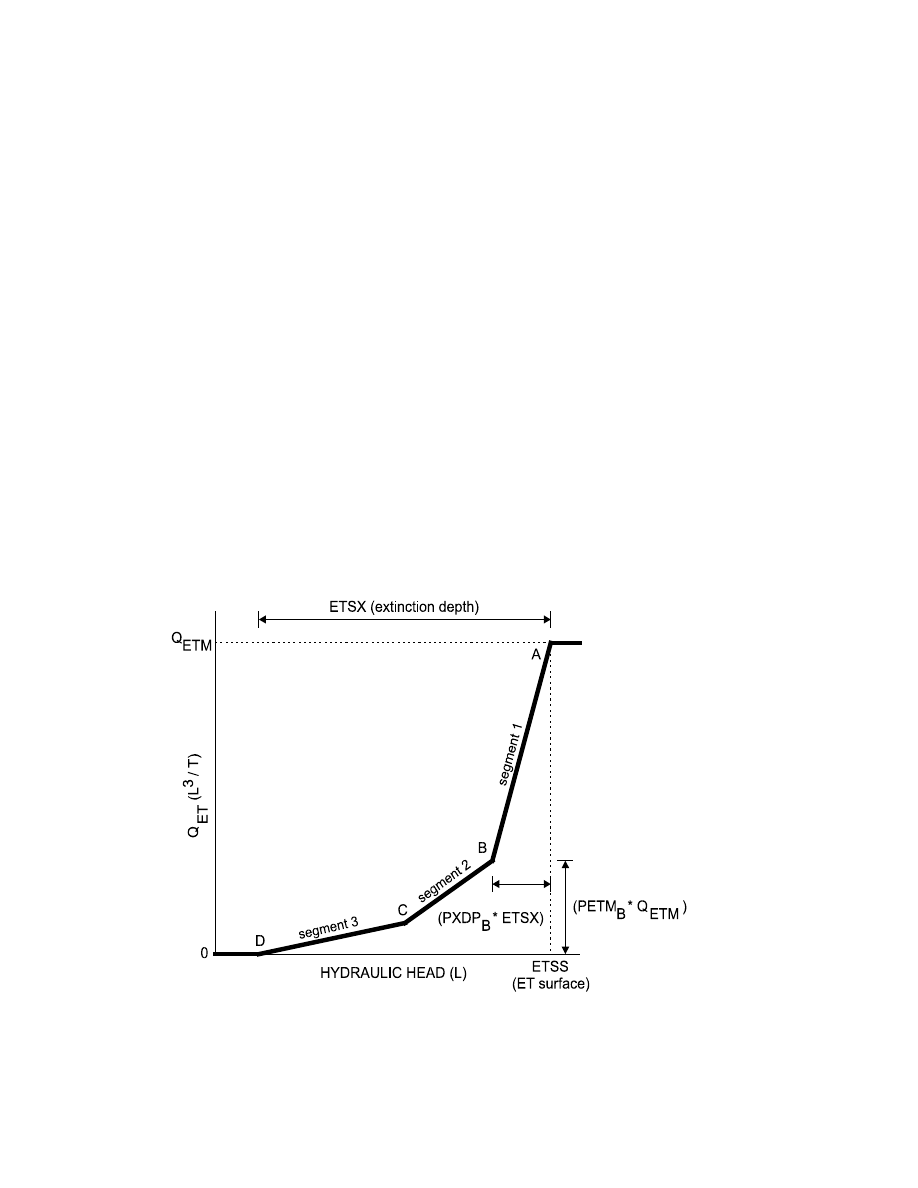
Figure 2 illustrates a possible function relating volumetric evapotranspiration rate to head for a situation
where three segments are used. The function in the variable interval is defined by the segments AB, BC, and CD.
Points A and D are determined by the ET surface (ETSS), the product of the maximum evapotranspiration flux
rate and the cell area (Q
ETM
), and the extinction depth (ETSX). Points B and C are intermediate segment
endpoints. The user inputs PXDP and PETM to define each intermediate endpoint. For the cell corresponding to
figure 2, PXDP
B
equals 0.2, PETM
B
equals 0.3, PXDP
C
equals 0.5, and PETM
C
equals 0.1.
In some cases a segmented relation between evapotranspiration rate and head in one part of the model area
and a simple linear relation in another part may be desired. The simple linear relation can be modeled by speci-
fying PXDP and PETM such that PETM = (1 – PXDP) for each intermediate endpoint. To use a simple linear rela-
tion everywhere in the model area, the modeler can specify that only one segment is to be used; use of this
approach results in evapotranspiration being simulated using the methodology of the EVT Package.
Figure 2.-- Volumetric evapotranspiration rate, Q
ET
, as a function of head for a situation
in which the function in the variable interval is defined using three segments. ETSX is
the extinction depth, ETSS is the ET surface, and Q
ETM
is the product of the maximum
evapotranspiration flux rate and the cell area. PETM
B
and PXDP
B
define the location of
point B.

Evapotranspiration Segments Package
5
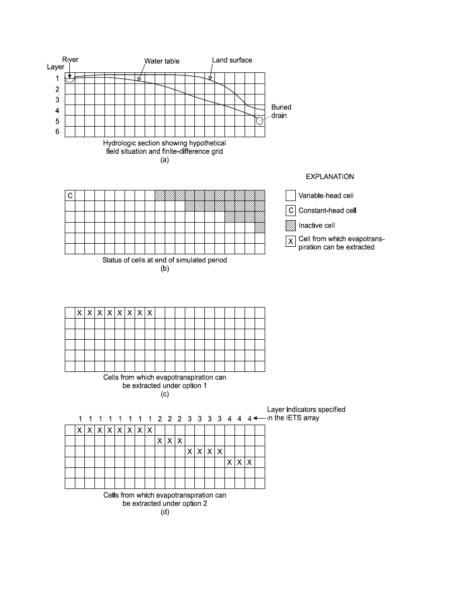
As for the EVT Package, the ETS1 Package provides two options for specifying the layer from which
evapotranspiration is to be extracted. Figure 3 shows a hypothetical field situation. Figure 3a shows a hydrogeo-
logic section of the situation under study, and figure 3b shows the distribution of variable-head, constant-head,
and inactive (no-flow) cells. When option 1 (fig. 3c) is used, evapotranspiration is drawn only from the uppermost
model layer; in the problem shown, the presence of no-flow-cells in this layer eliminates evapotranspiration from
the right side of the model. Figure 3d illustrates the use of option 2, where the user specifies layer numbers to indi-
cate which layer is allowed to have evapotranspiration in each vertical column of cells.
Input Instructions for the Evapotranspiration Segments Package
Input to the ETS1 Package is read from the file that is type “ETS” in the name file. All single-valued vari-
ables are free format if the option “FREE” is specified in the Basic Package input file; otherwise, the variables
have 10-character fields. Arrays are read by an array-reading utility module, either U2DREL or U2DINT
(Harbaugh and others, 2000), as indicated. Optional variables are shown in brackets.
FOR EACH SIMULATION
0. [#Text]
Item 0 is optional—“#” must be in column 1. Item 0 can be repeated as many times as desired.
1. NETSOP IETSCB NPETS NETSEG
2. [PARNAM PARTYP Parval NCLU]
3. [Mltarr Zonarr IZ]
Each repetition of Item 3 record is called a parameter cluster. Repeat Item 3 NCLU times.
Repeat Items 2 and 3 for each parameter to be defined (that is, NPETS times). Items 2 and 3 are omitted if
NPETS = 0.
FOR EACH STRESS PERIOD
4. INETSS INETSR INETSX [INIETS [INSGDF]]
5. [ETSS(NCOL,NROW)] –
U2DREL – If INETSS
≥
0
6. [ETSR(NCOL,NROW)] –
U2DREL – If NPETS = 0 and if INETSR
≥
0
7. [Pname [IETSPF]] –
If NPETS > 0 and if INETSR > 0
Either Item 6 or Item 7 may be read, but not both. If Item 7 is read, it is repeated INETSR times.
8. [ETSX(NCOL,NROW)] –
U2DREL – If INETSX
≥
0
9. [IETS(NCOL,NROW)] –
U2DINT – If NETSOP = 2 and if INIETS
≥
0
10. [PXDP(NCOL,NROW)] –
U2DREL – If NETSEG > 1 and INSGDF
≥
0
11. [PETM(NCOL,NROW)] –
U2DREL – If NETSEG > 1 and INSGDF
≥
0
If NETSEG > 1, (NETSEG
−
1) repetitions of items 10 and 11 are read. If NETSEG > 2, items 10 and 11
are read for the uppermost segment intersection, followed by repetitions of items 10 and 11 for successively
lower intersections.
6
MODFLOW-2000—Documentation of Packages for Simulating Evapotranspiration with a
Segmented Function (ETS1) and Drains with Return Flow (DRT1)
Figure 3.-- Hypothetical field situation showing cells from which evapotranspiration can be extracted under the two
options available in the ETS1 Package.

Evapotranspiration Segments Package
7
Explanation of Variables Read by the Evapotranspiration Segments Package
Text—is a character variable (79 characters) that starts in column 2. Any characters can be included in Text. The
“#” character must be in column 1. Lines beginning with “#” are restricted to these first lines of the input file. Text
is written to the LIST output file when the input file is read and provides an opportunity for the user to include
information about the model both in the input file and the associated output file.
NETSOP—is the evapotranspiration (ET) option code. ET variables (ET surface, maximum ET rate, and extinc-
tion depth) are specified in layer variables, ETSS, ETSR, and ETSX, with one value for each vertical column of
cells in the model grid. Accordingly, ET is calculated for one cell in each vertical column. The option codes deter-
mine the cell within a column for which ET will be calculated.
If NETSOP = 1, ET is calculated only for cells in the top grid layer.
If NETSOP = 2, the cell for each vertical column is specified by the user in variable IETS.
IETSCB—is a flag and a unit number.
If IETSCB > 0, it is the unit number to which ETS1-Package cell-by-cell flow terms will be written when
“SAVE BUDGET” or a non-zero value for ICBCFL is specified in Output Control (Harbaugh and
others, 2000). IETSCB must be a unit number associated with a file listed with type “DATA(BINARY)”
or “DATAGLO(BINARY)” in the name file.
If IETSCB
≤
0, ETS1-Package cell-by-cell flow terms will not be written.
NPETS—is the number of evapotranspiration-segments parameters.
NETSEG—is the number of segments used to define the relation of evapotranspiration rate to hydraulic head in
the interval where the evapotranspiration rate is variable.
PARNAM—is the name of a parameter to be defined. This name can consist of 1 to 10 characters and is not case
sensitive. That is, any combination of the same characters with different case will be equivalent.
PARTYP—is the type of parameter to be defined. For the ETS1 Package, the only allowed parameter type is
“ETS,” which defines values of the maximum ET flux.
Parval—is the parameter value. The units of Parval times Mltarr (if used) must be (LT
–1
). This parameter value
may be overridden by a value in the Sensitivity Process input file or by a value generated by the Parameter-
Estimation Process.
NCLU—is the number of clusters required to define a parameter. Each repetition of Item 3 record is a cluster
(variables Mltarr, Zonarr, and IZ). Usually only one cluster is needed to define an ETS parameter; however, more
than one cluster may be listed.
Mltarr—is the name of the multiplier array to be used to define the values determined by a parameter. The units of
Parval times Mltarr must be (LT
−
1
). The name “NONE” means there is no multiplier array, and the values will be
set equal to Parval.
Zonarr—is the name of the zone array to be used to define the cells associated with a parameter. The name “ALL”
means there is no zone array, and all cells are associated with the parameter.
IZ—is up to 10 zone numbers (separated by spaces) that define the cells associated with a parameter. These values
are not used if Zonarr is specified as “ALL.” Values can be positive or negative, but 0 is not allowed. The end of
the line, a zero value, or a non-numeric entry terminates the list of values.
INETSS—is the ET surface (ETSS) read flag.
If INETSS
≥
0, a layer variable containing the ET surface (ETSS) will be read from item 5 in the ETS1
input file.
If INETSS < 0, the ET surface from the preceding stress period will be reused.

8
MODFLOW-2000—Documentation of Packages for Simulating Evapotranspiration with a
Segmented Function (ETS1) and Drains with Return Flow (DRT1)
INETSR—is the ETSR read flag. Its function depends on whether or not parameters are being used.
If no parameters are being used (NPETS = 0):
If INETSR
≥
0, a layer variable containing the maximum ET rate (ETSR) will be read from item 6 in the
ETS1 input file.
If INETSR < 0, the maximum ET rate from the preceding stress period will be reused.
If parameters are being used (NPETS > 0):
If INETSR > 0, INETSR is the number of parameters used to define ETSR in the current stress period.
Item 7 defines the names of the parameters.
If INETSR < 0, ETS parameters from the preceding stress period are used.
INETSR = 0 is not allowed. That is, when parameters are used, at least one parameter must be specified
for each stress period.
INETSX—is the extinction depth (ETSX) read flag.
If INETSX
≥
0, a layer variable containing the extinction depth (ETSX) will be read from item 8 in the
ETS1 input file.
If INETSX < 0, the extinction depth from the preceding stress period will be reused.
INIETS—is the layer indicator (IETS) read flag. It is read if the ET option (NETSOP) is equal to two or if
NETSEG > 1. If NETSEG > 1 and NETSOP is not equal to two, INIETS is ignored and IETS is not read.
If INIETS
≥
0, a layer variable containing the layer indicators (IETS) will be read from item 9 in the ETS1
input file.
If INIETS < 0, layer indicators used during the preceding stress period will be reused.
INSGDF—is the segment definition read flag. It is read only if NETSEG > 1.
If INSGDF
≥
0, two layer variables to define PXDP and PETM for each of (NETSEG – 1) segment inter-
sections are read from items 10 and 11, respectively, of the ETS1 input file.
If INSGDF < 0, PXDP and PETM from the preceding stress period will be reused.
ETSS—is the elevation of the ET surface (L).
ETSR—is the maximum ET flux (volumetric flow rate per unit area, LT
–1
).
Pname—is the name of a parameter that will be used to define the ETSR variable in the current stress period.
IETSPF—is an optional format code for printing the ETSR variable after it has been defined by parameters. The for-
mat codes are the same as those used in the U2DREL array reading utility module (Harbaugh and others, 2000).
ETSX—is the ET extinction depth (L). This variable is read only if INETSX
≥
0.
IETS—is the layer indicator variable. For each horizontal location, IETS indicates the layer from which ET is
removed. It is read only if the ET option (NETSOP) is equal to two and if INIETS
≥
0.
PXDP—is a proportion of the extinction depth (dimensionless), measured downward from the ET surface, which,
with PETM, defines the shape of the relation between the evapotranspiration rate and head. The value of PXDP
must be between 0.0 and 1.0, inclusive. Repetitions of PXDP and PETM are read in sequence such that the first
occurrence represents the bottom of the first segment, and subsequent repetitions represent the bottom of succes-
sively lower segments. Accordingly, PXDP values for later repetitions (representing lower segments) should be
greater than PXDP values for earlier repetitions.
PETM—is a proportion of the maximum evapotranspiration rate (dimensionless) which, with PXDP, defines the
shape of the relation between the evapotranspiration rate and head. The value of PETM should be between 0.0 and
1.0, inclusive. Repetitions of PXDP and PETM are read in sequence such that the first occurrence represents the
bottom of the first segment, and subsequent repetitions represent the bottoms of successively lower segments.
Accordingly, PETM values for later repetitions (representing lower segments) generally would be less than PETM
values for earlier repetitions.
Evapotranspiration Segments Package
9
ETS1 Example Problem
A simple example problem was devised to demonstrate that the ETS1 Package correctly calculates evapo-
transpiration when the relation of evapotranspiration rate to head is segmented. For this problem a grid of 11 rows
by 11 columns in one layer was used to simulate an unconfined aquifer with a uniform base elevation of 0 ft. All
row and column widths were 100 ft. All cells in column 1 had a specified head of 50 ft, and all cells in column 11
had a specified head of 100 ft. Hydraulic conductivity of the aquifer material was 0.05 ft/d, and the system was
modeled in steady state. Evapotranspiration was the only stress, and it was simulated with the ETS1 Package for
one simulation and with the EVT Package (Harbaugh and others, 2000) for a second simulation. The input files
for these simulations are listed in Appendix A.
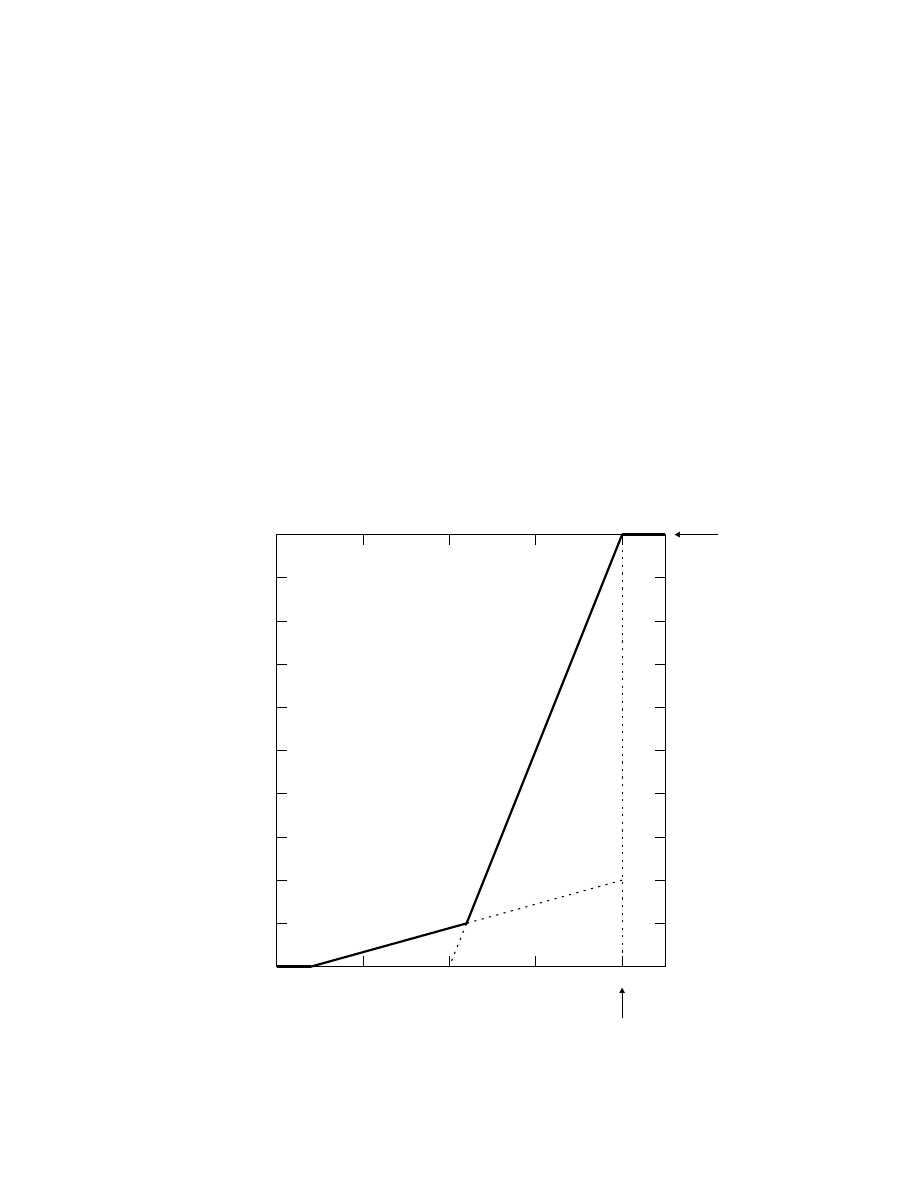
A two-segment function was assumed to relate evapotranspiration rate to head for both simulations (fig. 4).
The ET surface for the modeled area was defined as 100 ft, and the maximum evapotranspiration rate at the ET
surface was 0.01 ft/d. Each cell in the model had an area of 10,000 ft
2
, so the maximum evapotranspiration rate
over the area of one cell was 100 ft
3
/d. Segment 1 applies where the head is between 82 and 100 ft, and segment 2
applies where the head is between 64 and 82 ft. The two segments intersect at a depth below the ET surface of
18 ft, which corresponds to an elevation of 82 ft. At the intersection of the two segments, the evapotranspiration
rate is 0.001 ft/d (10 ft
3
/d over the cell area). The evapotranspiration rate is zero where the head is at or below
64 ft, which represents an extinction depth of 36 ft.
ET surface
Q
ETM
Q
ET
(L
3
/
T)
HYDRAULIC HEAD (L)
segment 2
segment 1
100
90
80
70
60
10
20
30
40
50
60
70
80
90
100
0
Figure 4.-- Segmented relation of volumetric evapotranspiration rate to head for one cell in the
ETS1 example problem.

10
MODFLOW-2000—Documentation of Packages for Simulating Evapotranspiration with a
Segmented Function (ETS1) and Drains with Return Flow (DRT1)
For the simulation using the ETS1 Package, the two-segment relation of evapotranspiration rate to head was
specified uniformly over the model domain. The extinction depth was specified as 36 ft, and the maximum evapo-
transpiration rate was specified as 0.01 ft/d. The two-segment function requires definition of one PXDP array
and one PETM array. PXDP was specified as 0.5 (18 ft / 36 ft) everywhere, and PETM was specified as
0.1 [(0.001 ft/d) / (0.01 ft/d)] everywhere. Appendix A lists the output file for this simulation. When evapotranspi-
ration is simulated with the ETS1 Package, as calculated head changes with changing stresses, the correct segment
is applied at each cell without the need for intervention by the modeler.
For the simulation using the EVT Package, the model domain was divided into two zones such that
segment 1 would apply in zone 1 (columns 1 through 9) and segment 2 would apply in zone 2 (columns 10 and
11). Segment 1 was simulated in zone 1 by specifying an extinction depth of 20 ft and a maximum evapotranspira-
tion rate of 0.01 ft/d. Segment 2 was simulated in zone 2 by specifying an extinction depth of 36 ft and a
maximum evapotranspiration rate of 0.002 ft/d. Appendix A includes the calculated head distribution and
volumetric water budget for this simulation. The calculated head distribution was identical to that obtained with
the ETS1 Package, and the volumetric budgets were identical within round-off error. Note that if head at a partic-
ular cell changes as a result of changing stresses, the function that applies at the cell does not change, even if the
head change causes the head to become less than or greater than the intersection elevation of 82 ft. To ensure that
each cell is simulated with the appropriate function, the modeler would need to adjust the zone distribution
manually.
Module Documentation for the Evapotranspiration Segments Package
The ETS1 Package is composed of six modules. Five of these are primary modules that are part of the
Ground-Water Flow Process (Harbaugh and others, 2000). Primary modules are called directly from the main
MODFLOW-2000 program unit. The sixth module is a primary module that is part of the Sensitivity Process (Hill
and others, 2000). The six modules are:
GWF1ETS1AL—Reads options and allocates memory for data arrays. GWF1ETS1AL is part of the Ground-
Water Flow Process and is in source-code file gwf1ets1.f.
GWF1ETS1RQ—Reads parameter definitions. GWF1ETS1RQ is part of the Ground-Water Flow Process and is
in source-code file gwf1ets1.f.
GWF1ETS1RP—Reads ETS1 data arrays and, if ETS parameters are defined, performs substitution using
parameter values. GWF1ETS1RP is part of the Ground-Water Flow Process and is in source-code file gwf1ets1.f.
GWF1ETS1FM—Formulates terms needed to solve the ground-water flow equation and adds them to the head-
coefficient array (HCOF) and to the right-hand side array (RHS). GWF1ETS1FM is part of the Ground-Water
Flow Process and is in source-code file gwf1ets1.f.
GWF1ETS1BD—Computes flow rates simulated as evapotranspiration and writes cell-by-cell flow rates if that
option is selected. GWF1ETS1BD is part of the Ground-Water Flow Process and is in source-code file gwf1ets1.f.
SEN1ETS1FM—Formulates terms needed to solve the sensitivity equation and adds them to the right-hand side
array (RHS). SEN1ETS1FM is part of the Sensitivity Process and is in source-code file sen1ets1.f.

Evapotranspiration Segments Package
11
Module GWF1ETS1AL
Narrative for Module GWF1ETS1AL
This module reads package options from item 1 of the ETS1 input file and allocates space in the RX and
IR arrays (Harbaugh and others, 2000). Output is written to the LIST file.
1.
Print a message identifying the ETS1 Package.
2.
Read and print comment lines (item 0) introduced with the “#” character.
3.
Read values for the option indicator (NETSOP), the unit number for cell-by-cell flow terms (IETSCB), the
number of parameters (NPETS), and number of segments (NETSEG). Ensure option is valid and print
messages showing option and, if IETSCB is greater than zero, the unit number. Print numbers of
parameters and segments.
4.
Allocate space in the RX array for the ETSR, ETSX, and ETSS arrays and for the PXDP and PETM arrays if
needed. Allocate space in the IR array for the IETS array.
5.
Print a message showing amount of storage required by the ETS1 Package.
Listing for Module GWF1ETS1AL
SUBROUTINE GWF1ETS1AL(ISUM,ISUMI,LCIETS,LCETSR,LCETSX,LCETSS,NCOL,
& NROW,NETSOP,IN,IOUT,IETSCB,IFREFM,NPETS,
& IETSPF,NETSEG,LCPXDP,LCPETM,NSEGAR)
C
C-----VERSION 20000620 ERB
C ******************************************************************
C ALLOCATE ARRAY STORAGE FOR EVAPOTRANSPIRATION SEGMENTS
C ******************************************************************
C
C SPECIFICATIONS:
C ------------------------------------------------------------------
CHARACTER*200 LINE
C ------------------------------------------------------------------
500 FORMAT(1X,/
&1X,'ETS1 -- EVAPOTRANSPIRATION SEGMENTS PACKAGE, VERSION 1,',
& ' 5/2/2000',/,9X,'INPUT READ FROM UNIT',I3)
510 FORMAT(
&1X,I5,' SEGMENTS DEFINE EVAPOTRANSPIRATION RATE FUNCTION')
520 FORMAT(' EVAPOTRANSPIRATION RATE FUNCTION IS LINEAR')
530 FORMAT(
&' ERROR: EVAPOTRANSPIRATION RATE FUNCTION MUST CONTAIN AT',/,
&' LEAST ONE SEGMENT -- STOP EXECUTION (GWF1ETS1AL)')
540 FORMAT(1X,'ILLEGAL ET OPTION CODE. SIMULATION ABORTING')
550 FORMAT(1X,'OPTION 1 -- EVAPOTRANSPIRATION FROM TOP LAYER')
560 FORMAT(1X,'OPTION 2 -- EVAPOTRANSPIRATION FROM ONE SPECIFIED',
& ' NODE IN EACH VERTICAL COLUMN')
570 FORMAT(1X,'CELL-BY-CELL FLOWS WILL BE SAVED ON UNIT',I3)
580 FORMAT(1X,I10,' ELEMENTS IN RX ARRAY ARE USED BY ETS')
590 FORMAT(1X,I10,' ELEMENTS IN IR ARRAY ARE USED BY ETS')
C
C1------IDENTIFY PACKAGE.
IETSPF=20
WRITE(IOUT,500)IN
C
C READ COMMENT LINE(S) (ITEM 0)
CALL URDCOM(IN,IOUT,LINE)

12
MODFLOW-2000—Documentation of Packages for Simulating Evapotranspiration with a
Segmented Function (ETS1) and Drains with Return Flow (DRT1)
C
C2------READ ET OPTION (NETSOP), UNIT OR FLAG FOR CELL-BY-CELL FLOW
C TERMS (IETSCB), NUMBER OF PARAMETERS (NPETS), AND NUMBER OF
C SEGMENTS (NETSEG) (ITEM 1)
IF (IFREFM.EQ.0) THEN
READ(LINE,'(4I10)') NETSOP,IETSCB,NPETS,NETSEG
ELSE
LLOC=1
CALL URWORD(LINE,LLOC,ISTART,ISTOP,2,NETSOP,R,IOUT,IN)
CALL URWORD(LINE,LLOC,ISTART,ISTOP,2,IETSCB,R,IOUT,IN)
CALL URWORD(LINE,LLOC,ISTART,ISTOP,2,NPETS,R,IOUT,IN)
CALL URWORD(LINE,LLOC,ISTART,ISTOP,2,NETSEG,R,IOUT,IN)
ENDIF
C
C3------CHECK TO SEE THAT ET OPTION IS LEGAL.
IF (NETSOP.GE.1.AND.NETSOP.LE.2) GO TO 10
C
C3A-----OPTION IS ILLEGAL -- PRINT A MESSAGE & ABORT SIMULATION.
WRITE(IOUT,540)
STOP
C
C4------OPTION IS LEGAL -- PRINT THE OPTION CODE.
10 CONTINUE
IF (NETSOP.EQ.1) WRITE(IOUT,550)
IF (NETSOP.EQ.2) WRITE(IOUT,560)
C
C5------IF CELL-BY-CELL FLOWS ARE TO BE SAVED, THEN PRINT UNIT NUMBER.
IF (IETSCB.GT.0) WRITE(IOUT,570) IETSCB
C
C-----PRINT NUMBER OF PARAMETERS TO BE USED
CALL UPARARRAL(-1,IOUT,LINE,NPETS)
C
C PRINT MESSAGE IDENTIFYING NUMBER OF SEGMENTS IN ET VS. HEAD CURVE
IF(NETSEG.GT.1) THEN
WRITE(IOUT,510) NETSEG
NSEGAR = NETSEG - 1
ELSEIF (NETSEG.EQ.1) THEN
WRITE(IOUT,520)
NSEGAR = 1
ELSE
WRITE(IOUT,530)
STOP
ENDIF
C
C6------ALLOCATE SPACE FOR THE ARRAYS ETSR, ETSX, ETSS, PXDP, AND PETM.
IRK=ISUM
LCETSR=ISUM
ISUM=ISUM+NCOL*NROW
LCETSX=ISUM
ISUM=ISUM+NCOL*NROW
LCETSS=ISUM
ISUM=ISUM+NCOL*NROW
IF (NETSEG.GT.1) THEN
LCPXDP=ISUM
ISUM=ISUM+NCOL*NROW*(NETSEG-1)
LCPETM=ISUM
ISUM=ISUM+NCOL*NROW*(NETSEG-1)
ELSE
LCPXDP=1
LCPETM=1
ENDIF
C

Evapotranspiration Segments Package
13
C7------ALLOCATE SPACE FOR LAYER INDICATOR ARRAY (IETS) EVEN IF ET
C7------OPTION IS NOT 2, TO AVOID ERROR OF ARRAY (IR) NOT LARGE ENOUGH
LCIETS=ISUMI
ISUMI=ISUMI+NCOL*NROW
C
C8------CALCULATE & PRINT AMOUNT OF SPACE USED BY ET PACKAGE.
IRK=ISUM-IRK
WRITE(IOUT,580)IRK
IRK=NCOL*NROW
WRITE(IOUT,590)IRK
C
C9------RETURN.
RETURN
END
List of Variables for Module GWF1ETS1AL
Variable
Range
Definition
IETSCB
Package
Cell-by-cell flag and unit number
IETSPF
Package
Format code for printing the ETSR array when defined by parameters
IFREFM
Process
Flag indicating if variables are to be read in free format
IN
Module
Unit number of input file
IOUT
Global
Unit number of LIST output file
IRK
Module
Number of array elements required
ISTART
Module
Starting position of parsed word
ISTOP
Module
Ending position of parsed word
ISUM
Module
Pointer used to keep track of position in RX
ISUMI
Module
Pointer used to keep track of position in IR
LCETSR
Package
Position in RX of first element of ETSR
LCETSS
Package
Position in RX of first element of ETSS
LCETSX
Package
Position in RX of first element of ETSX
LCIETS
Package
Position in IR of first element of IETS
LCPETM
Package
Position in RX of first element of PETM
LCPXDP
Package
Position in RX of first element of PXDP
LINE
Module
Contents of one line read from input file
LLOC
Module
Pointer used to keep track of position in LINE
NCOL
Global
Number of columns in model grid
NETSEG
Package
Number of segments used to relate evapotranspiration rate to head
NETSOP
Package
Flag identifying layer distribution method for simulating evapotranspiration
NPETS
Package
Number of evapotranspiration parameters
NROW
Global
Number of rows in model grid
NSEGAR
Package
Dimensioning variable for PXDP and PETM
R
Module
Dummy real variable
14
MODFLOW-2000—Documentation of Packages for Simulating Evapotranspiration with a
Segmented Function (ETS1) and Drains with Return Flow (DRT1)
Module GWF1ETS1RQ
Narrative for Module GWF1ETS1RQ
This module reads parameter definitions from items 2 and 3 of the ETS1 input file. Output is written to the
GLOBAL file.
1.
Print a message indicating how many evapotranspiration-segments parameters are being used.
2.
For each evapotranspiration-segments parameter, call a utility that reads the parameter definition. The utility
reads a record containing the parameter name, type, value, and number of clusters used to define the
parameter, then reads one or more records containing a multiplier array name, zone array name, and a list
of zone numbers.
Listing for Module GWF1ETS1RQ
SUBROUTINE GWF1ETS1RQ(IN,IOUT,NPETS,ITERP)
C
C-----VERSION 20000620 ERB
C ******************************************************************
C READ EVAPOTRANSPIRATION SEGMENTS PARAMETER DEFINITIONS
C ******************************************************************
C
C SPECIFICATIONS:
C ------------------------------------------------------------------
CHARACTER*4 PTYP
C ------------------------------------------------------------------
C
C-------READ NAMED PARAMETERS
IF (ITERP.EQ.1) WRITE(IOUT,5) NPETS
5 FORMAT(1X,//1X,I5,' Evapotranspiration segments parameters')
IF (NPETS.GT.0) THEN
DO 20 K=1,NPETS
C UPARARRRP READS PARAMETER NAME AND DEFINITION (ITEMS 2 AND 3)
CALL UPARARRRP(IN,IOUT,N,0,PTYP,ITERP)
IF(PTYP.NE.'ETS') THEN
WRITE(IOUT,7)
7 FORMAT(1X,'Parameter type must be ETS')
STOP
ENDIF
20 CONTINUE
ENDIF
C
C8------RETURN
60 RETURN
END
List of Variables for Module GWF1ETS1RQ
Variable
Range
Definition
IN
Module
Unit number of input file
IOUT
Global
Unit number of GLOBAL output file
ITERP
Global
Parameter-estimation iteration number
K
Module
Counter for parameters
N
Module
Dummy integer variable
NPETS
Package
Number of evapotranspiration-segments parameters
PTYP
Global
Parameter type

Evapotranspiration Segments Package
15
Module GWF1ETS1RP
Narrative for Module GWF1ETS1RP
This module is called each stress period to read items 4 through 11 of the ETS1 input file. Output is written
to the LIST file.
1.
Read INETSS, INETSR, INETSX, INIETS, and INSGDF or a subset of these, depending on the option
selected and the number of segments. These flags indicate which arrays need to be defined (or redefined)
for the stress period.
2.
If INETSS
≥
0, call a utility to read data into ETSS; otherwise, print a message indicating that ETSS used in
the previous stress period will be reused.
3.
If INETSR
≥
0, define ETSR either by reading directly (if NPETS = 0) or by calling a utility that generates
the array by substitution, using evapotranspiration-segments parameters and their definitions. Multiply
ETSR by the cell area to get a volumetric rate. If INETSR < 0, print a message indicating that ETSR used
in the previous stress period will be reused.
4.
If INETSX
≥
0, call a utility to read data into ETSX; otherwise, print a message indicating that ETSX used in
the previous stress period will be reused.
5.
If NETSOP = 2 and INIETS
≥
0, call a utility to read data into IETS. If NETSOP = 2 and INIETS < 0, print
a message indicating that IETS used in the previous stress period will be reused.
6.
If NETSEG > 1 and INSGDF
≥
0, make calls to a utility to read data into PXDP and PETM for (NETSEG – 1)
segment intersections. If NETSEG > 1 and INSGDF < 0, print a message indicating that PXDP and PETM
used in the previous stress period will be reused.
Listing for Module GWF1ETS1RP
SUBROUTINE GWF1ETS1RP(NETSOP,IETS,ETSR,ETSX,ETSS,DELR,DELC,NCOL,
& NROW,IN,IOUT,IFREFM,NPETS,RMLT,IZON,NMLTAR,
& NZONAR,IETSPF,NETSEG,PXDP,PETM,NSEGAR)
C
C VERSION 20000620 ERB
C ******************************************************************
C READ EVAPOTRANSPIRATION DATA, AND PERFORM SUBSTITUTION USING
C PARAMETER VALUES IF ETS PARAMETERS ARE DEFINED
C ******************************************************************
C
C SPECIFICATIONS:
C ------------------------------------------------------------------
CHARACTER*24 ANAME(6)
DIMENSION IETS(NCOL,NROW),ETSR(NCOL,NROW),ETSX(NCOL,NROW),
& ETSS(NCOL,NROW),DELR(NCOL),DELC(NROW),
& RMLT(NCOL,NROW,NMLTAR),IZON(NCOL,NROW,NZONAR),
& PXDP(NCOL,NROW,NSEGAR),PETM(NCOL,NROW,NSEGAR)
C
DATA ANAME(1) /' ET LAYER INDEX (IETS)'/
DATA ANAME(2) /' ET SURFACE (ETSS)'/
DATA ANAME(3) /' EVAPOTRANS. RATE (ETSR)'/
DATA ANAME(4) /' EXTINCTION DEPTH (ETSX)'/
DATA ANAME(5) /'EXTINCT. DEP. PROPORTION'/
DATA ANAME(6) /' ET RATE PROPORTION'/
C ------------------------------------------------------------------
C
C1------READ FLAGS SHOWING WHETHER DATA FROM PREVIOUS STRESS PERIOD ARE
C TO BE REUSED.

16
MODFLOW-2000—Documentation of Packages for Simulating Evapotranspiration with a
Segmented Function (ETS1) and Drains with Return Flow (DRT1)
IF (NETSEG.GT.1) THEN
IF(IFREFM.EQ.0) THEN
READ(IN,'(5I10)') INETSS,INETSR,INETSX,INIETS,INSGDF
ELSE
READ(IN,*) INETSS,INETSR,INETSX,INIETS,INSGDF
ENDIF
ELSE
IF(NETSOP.EQ.2) THEN
IF(IFREFM.EQ.0) THEN
READ(IN,'(4I10)') INETSS,INETSR,INETSX,INIETS
ELSE
READ(IN,*) INETSS,INETSR,INETSX,INIETS
ENDIF
ELSE
IF(IFREFM.EQ.0) THEN
READ(IN,'(3I10)') INETSS,INETSR,INETSX
ELSE
READ(IN,*) INETSS,INETSR,INETSX
ENDIF
ENDIF
ENDIF
C
C2------TEST INETSS TO SEE WHERE SURFACE ELEVATION COMES FROM.
IF (INETSS.LT.0) THEN
C2A------IF INETSS<0 THEN REUSE SURFACE ARRAY FROM LAST STRESS PERIOD
WRITE(IOUT,10)
10 FORMAT(1X,/1X,'REUSING ETSS FROM LAST STRESS PERIOD')
ELSE
C3-------IF INETSS=>0 THEN CALL MODULE U2DREL TO READ SURFACE.
CALL U2DREL(ETSS,ANAME(2),NROW,NCOL,0,IN,IOUT)
ENDIF
C
C4------TEST INETSR TO SEE WHERE MAX ET RATE COMES FROM.
IF (INETSR.LT.0) THEN
C4A-----IF INETSR<0 THEN REUSE MAX ET RATE.
WRITE(IOUT,20)
20 FORMAT(1X,/1X,'REUSING ETSR FROM LAST STRESS PERIOD')
ELSE
C5------IF INETSR=>0 CALL MODULE U2DREL TO READ MAX ET RATE.
IF(NPETS.EQ.0) THEN
CALL U2DREL(ETSR,ANAME(3),NROW,NCOL,0,IN,IOUT)
ELSE
C INETSR is the number of parameters to use this stress period
CALL PRESET('ETS')
WRITE(IOUT,30)
30 FORMAT(1X,///1X,
& 'ETSR array defined by the following parameters:')
IF (INETSR.EQ.0) THEN
WRITE(IOUT,35)
35 FORMAT(' ERROR: When parameters are defined for the ETS',
& ' Package, at least one parameter',/,' must be specified',
& ' each stress period -- STOP EXECUTION (GWF1ETS1RP)')
STOP
ENDIF
CALL UPARARRSUB2(ETSR,NCOL,NROW,0,INETSR,IN,IOUT,'ETS',
& ANAME(3),'ETS',IETSPF,RMLT,IZON,NMLTAR,
& NZONAR)
ENDIF
C
C6------MULTIPLY MAX ET RATE BY CELL AREA TO GET VOLUMETRIC RATE
DO 50 IR=1,NROW
DO 40 IC=1,NCOL
ETSR(IC,IR)=ETSR(IC,IR)*DELR(IC)*DELC(IR)
40 CONTINUE
50 CONTINUE
ENDIF
Evapotranspiration Segments Package
17
C
C7------TEST INETSX TO SEE WHERE EXTINCTION DEPTH COMES FROM
IF (INETSX.LT.0) THEN
C7A------IF INETSX<0 REUSE EXTINCTION DEPTH FROM LAST STRESS PERIOD
WRITE(IOUT,60)
60 FORMAT(1X,/1X,'REUSING ETSX FROM LAST STRESS PERIOD')
ELSE
C8-------IF INETSX=>0 CALL MODULE U2DREL TO READ EXTINCTION DEPTH
CALL U2DREL(ETSX,ANAME(4),NROW,NCOL,0,IN,IOUT)
ENDIF
C
C9------IF OPTION(NETSOP) IS 2 THEN WE NEED AN INDICATOR ARRAY.
IF (NETSOP.EQ.2) THEN
C10------IF INIETS<0 THEN REUSE LAYER INDICATOR ARRAY.
IF (INIETS.LT.0) THEN
WRITE(IOUT,70)
70 FORMAT(1X,/1X,'REUSING IETS FROM LAST STRESS PERIOD')
ELSE
C11------IF INIETS=>0 THEN CALL MODULE U2DINT TO READ INDICATOR ARRAY.
CALL U2DINT(IETS,ANAME(1),NROW,NCOL,0,IN,IOUT)
ENDIF
ENDIF
C
C12------IF ET FUNCTION IS SEGMENTED PXDP AND PETM ARRAYS ARE NEEDED.
IF (NETSEG.GT.1) THEN
C13------IF INSGDF<0 THEN REUSE PXDP AND PETM ARRAYS.
IF (INSGDF.LT.0) THEN
WRITE(IOUT,80)
80 FORMAT(1X,/1X,
& 'REUSING PXDP AND PETM FROM LAST STRESS PERIOD')
C14------IF INSGDF=>0 THEN CALL MODULE U2DREL TO READ PXDP AND PETM
C ARRAYS.
ELSE
DO 90 I = 1,NETSEG-1
WRITE(IOUT,100) I
CALL U2DREL(PXDP(1,1,I),ANAME(5),NROW,NCOL,0,IN,IOUT)
CALL U2DREL(PETM(1,1,I),ANAME(6),NROW,NCOL,0,IN,IOUT)
90 CONTINUE
ENDIF
ENDIF
100 FORMAT(/,' PXDP AND PETM ARRAYS FOR INTERSECTION ',I4,
&' OF HEAD/ET RELATION:')
C
C15-----RETURN
RETURN
END
List of Variables for Module GWF1ETS1RP
Variable
Range
Definition
ANAME
Module
Array content label
DELC
Global
Cell dimension in the column direction
DELR
Global
Cell dimension in the row direction
ETSR
Package
Maximum evapotranspiration rate
ETSS
Package
Evapotranspiration (ET) surface
ETSX
Package
Extinction depth
I
Module
Counter for segments
IC
Module
Column index

18
MODFLOW-2000—Documentation of Packages for Simulating Evapotranspiration with a
Segmented Function (ETS1) and Drains with Return Flow (DRT1)
Module GWF1ETS1FM
Narrative for Module GWF1ETS1FM
This module adds terms to the finite-difference equations to account for loss of water from the ground-water
system by evapotranspiration.
1.
For each cell in the horizontal model grid, determine the layer in which evapotranspiration is simulated and
add the terms to the equation for the cell. Do steps 2 through 10 for each cell in the horizontal model grid.
2.
Set the layer index to 1.
3.
If NETSOP = 2, get the layer index from the layer indicator array (IETS).
4.
If the cell is inactive or constant-head, skip steps 5 through 10.
5.
If the head in the cell is greater than or equal to the ET surface, add ETSR to the right-hand side array (RHS)
and move on to the next cell location. Skip steps 6 through 10.
IETS
Package
Layer indicator
IETSPF
Package
Format code for printing the ETSR array when defined by parameters
IFREFM
Process
Flag indicating if variables are to be read in free format
IN
Module
Unit number of input file
INETSR
Module
Flag indicating if ETSR is to be defined or redefined
INETSS
Module
Flag indicating if ETSS is to be read
INETSX
Module
Flag indicating if ETSX is to be read
INIETS
Module
Flag indicating if IETS is to be read
INSGDF
Module
Flag indicating if PXDP and PETM are to be read
IOUT
Global
Unit number of LIST output file
IR
Module
Row index
IZON
Global
Zone arrays
NCOL
Global
Number of columns in model grid
NETSEG
Package
Number of segments used to relate evapotranspiration rate to head
NETSOP
Package
Flag identifying layer distribution method for simulating evapotranspiration
NMLTAR
Global
Dimensioning variable for RMLT
NPETS
Package
Number of evapotranspiration parameters
NROW
Global
Number of rows in model grid
NSEGAR
Package
Dimensioning variable for PXDP and PETM
NZONAR
Global
Dimensioning variable for IZON
PETM
Package
Proportion of maximum evapotranspiration rate
PXDP
Package
Proportion of extinction depth
RMLT
Global
Multiplier arrays
Variable
Range
Definition

Evapotranspiration Segments Package
19
6.
If the head in the cell is less than the extinction elevation (ET surface minus extinction depth), no terms need
to be added to the finite-difference equation. Move on to the next cell location. Skip steps 7 through 10.
7.
If NETSEG = 1, add the term [–ETSR/ETSX] to HCOF and subtract the term [–ETSR*(ETSX –
ETSS)/ETSX] from RHS. Skip steps 8 through 10.
8.
If NETSEG > 1, set the proportion of extinction depth to 0.0 and the proportion of maximum ET rate to 1.0
to correspond to the top of the first segment, which is at the ET surface.
9.
Find the segment that applies to the head elevation by comparing the head with the bottom of successively
lower segments until the head is at or above the bottom of a segment. For the bottom of the final segment,
set the proportion of extinction depth to 1.0 and the proportion of maximum ET rate to 0.0.
10. Add the term [–(PETM
1
–PETM
2
)*ETSR/((PXDP
2
–PXDP
1
)*ETSX)] to HCOF and subtract the term
[(PETM
1
–PETM
2
)*ETSR/((PXDP
2
–PXDP
1
)*ETSX)*(ETSS–PXDP
1
*ETSX) – PETM
1
*ETSR] from
RHS, where the subscript 1 refers to the point at the top of the segment, and subscript 2 refers to the point
at the bottom of the segment.
Listing for Module GWF1ETS1FM
SUBROUTINE GWF1ETS1FM(NETSOP,IETS,ETSR,ETSX,ETSS,RHS,HCOF,IBOUND,
& HNEW,NCOL,NROW,NLAY,NETSEG,PXDP,PETM,
& NSEGAR)
C
C-----VERSION 20000620 ERB
C ******************************************************************
C ADD EVAPOTRANSPIRATION TO RHS AND HCOF
C ******************************************************************
C
C SPECIFICATIONS:
C ------------------------------------------------------------------
DOUBLE PRECISION HNEW, HH, SS, XX, DD, PXDP1, PXDP2
DIMENSION IETS(NCOL,NROW), ETSR(NCOL,NROW), ETSX(NCOL,NROW),
& ETSS(NCOL,NROW), RHS(NCOL,NROW,NLAY),
& HCOF(NCOL,NROW,NLAY), IBOUND(NCOL,NROW,NLAY),
& HNEW(NCOL,NROW,NLAY), PXDP(NCOL,NROW,NSEGAR),
& PETM(NCOL,NROW,NSEGAR)
C ------------------------------------------------------------------
C
C1------PROCESS EACH HORIZONTAL CELL LOCATION
DO 30 IR=1,NROW
DO 20 IC=1,NCOL
C
C2------SET THE LAYER INDEX EQUAL TO 1 .
IL=1
C
C3------IF OPTION 2 IS SPECIFIED THEN GET LAYER INDEX FROM IETS ARRAY
IF (NETSOP.EQ.2) IL=IETS(IC,IR)
C
C4------IF THE CELL IS EXTERNAL IGNORE IT.
IF (IBOUND(IC,IR,IL).GT.0) THEN
C=ETSR(IC,IR)
S=ETSS(IC,IR)
SS=S
HH=HNEW(IC,IR,IL)
C
C5------IF HEAD IN CELL IS GREATER THAN OR EQUAL TO ETSS, ET IS CONSTANT
IF(HH.GE.SS) THEN
C

20
MODFLOW-2000—Documentation of Packages for Simulating Evapotranspiration with a
Segmented Function (ETS1) and Drains with Return Flow (DRT1)
C5A-----SUBTRACT -ETSR FROM RHS
RHS(IC,IR,IL)=RHS(IC,IR,IL) + C
ELSE
C
C6------IF DEPTH TO WATER>=EXTINCTION DEPTH THEN ET IS 0
DD=SS-HH
X=ETSX(IC,IR)
XX=X
IF (DD.LT.XX) THEN
C7------VARIABLE RANGE. ADD ET TERMS TO BOTH RHS AND HCOF.
C
IF (NETSEG.GT.1) THEN
C DETERMINE WHICH SEGMENT APPLIES BASED ON HEAD, AND
C CALCULATE TERMS TO ADD TO RHS AND HCOF
C
C SET PROPORTIONS CORRESPONDING TO ETSS ELEVATION
PXDP1 = 0.0
PETM1 = 1.0
DO 10 ISEG = 1,NETSEG
C SET PROPORTIONS CORRESPONDING TO LOWER END OF
C SEGMENT
IF (ISEG.LT.NETSEG) THEN
PXDP2 = PXDP(IC,IR,ISEG)
PETM2 = PETM(IC,IR,ISEG)
ELSE
PXDP2 = 1.0
PETM2 = 0.0
ENDIF
IF (DD.LE.PXDP2*XX) THEN
C HEAD IS IN DOMAIN OF THIS SEGMENT
GOTO 15
ENDIF
C PROPORTIONS AT LOWER END OF SEGMENT WILL BE FOR
C UPPER END OF SEGMENT NEXT TIME THROUGH LOOP
PXDP1 = PXDP2
PETM1 = PETM2
10 CONTINUE
15 CONTINUE
C CALCULATE TERMS TO ADD TO RHS AND HCOF BASED ON
C SEGMENT THAT APPLIES AT HEAD ELEVATION
THCOF = -(PETM1-PETM2)*C/((PXDP2-PXDP1)*X)
TRHS = THCOF*(S-PXDP1*X) + PETM1*C
ELSE
C CALCULATE TERMS TO ADD TO RHS AND HCOF BASED ON SIMPLE
C LINEAR RELATION OF ET VS. HEAD
TRHS = C-C*S/X
THCOF = -C/X
ENDIF
RHS(IC,IR,IL)=RHS(IC,IR,IL)+TRHS
HCOF(IC,IR,IL)=HCOF(IC,IR,IL)+THCOF
ENDIF
ENDIF
ENDIF
20 CONTINUE
30 CONTINUE
C
C8------RETURN
RETURN
END

Evapotranspiration Segments Package
21
List of Variables for Module GWF1ETS1FM
Variable
Range
Definition
C
Module
Maximum evapotranspiration rate for a cell
DD
Module
Depth of head below ET surface
ETSR
Package
Maximum evapotranspiration rate
ETSS
Package
ET surface
ETSX
Package
Extinction depth
HCOF
Global
Head-coefficient array
HH
Module
Head in a cell
HNEW
Global
Head
IBOUND
Global
Boundary-status indicator
IC
Module
Column index
IETS
Package
Layer indicator
IL
Module
Layer index
IR
Module
Row index
ISEG
Module
Counter for segments
NCOL
Global
Number of columns in model grid
NETSEG
Package
Number of segments used to relate evapotranspiration rate to head
NETSOP
Package
Flag identifying layer distribution method for simulating evapotranspiration
NLAY
Global
Number of layers in model grid
NROW
Global
Number of rows in model grid
NSEGAR
Package
Dimensioning variable for PXDP and PETM
PETM
Package
Proportion of maximum evapotranspiration rate
PETM1
Module
Proportion of maximum evapotranspiration rate at the top of a segment
PETM2
Module
Proportion of maximum evapotranspiration rate at the bottom of a segment
PXDP
Package
Proportion of extinction depth
PXDP1
Module
Proportion of extinction depth at the top of a segment
PXDP2
Module
Proportion of extinction depth at the bottom of a segment
RHS
Global
Right-hand side
S
Module
ET surface for a cell
SS
Module
ET surface for a cell
THCOF
Module
Term to be added to HCOF
TRHS
Module
Term to be added to RHS
X
Module
Extinction depth for a cell
XX
Module
Extinction depth for a cell

22
MODFLOW-2000—Documentation of Packages for Simulating Evapotranspiration with a
Segmented Function (ETS1) and Drains with Return Flow (DRT1)
Module GWF1ETS1BD
Narrative for Module GWF1ETS1BD
This module calculates rates and volumes of water removed from the simulated system by evapotranspira-
tion. Output is written to the LIST file and, optionally, to the unformatted file associated with unit IETSCB.
1.
Set the rate accumulator RATOUT to zero.
2.
If budget terms will be saved, clear the buffer (BUFF) in which the budget terms will be accumulated.
3.
For each cell in the horizontal model grid calculate flow to evapotranspiration (steps 4 through 14).
4.
Set the layer index (IL) equal to 1.
5.
If NETSOP = 2, get the layer indicator (IETS).
6.
If the cell is inactive or constant-head, skip steps 7 through 14.
7.
If the head in the cell is greater than the elevation of the ET surface, set the ET rate for the cell equal to the
maximum ET rate. Skip steps 8 through 12.
8.
If the depth of the head in the cell below the ET surface is greater than the extinction depth, skip steps 9
through 12.
9.
If NETSEG = 1, calculate the evapotranspiration rate for the cell using the linear relation defined by
equation (1). Skip steps 10 through 12.
10. If NETSEG > 1, set the proportion of extinction depth to 0.0 and the proportion of maximum ET rate to 1.0 to
correspond to the top of the first segment, which is at the ET surface.
11. Find the segment that applies to the head elevation by comparing the head with the bottom of successively
lower segments until the head is at or above the bottom of a segment. For the bottom of the final segment,
set the proportion of extinction depth to 1.0 and the proportion of maximum ET rate to 0.0.
12. Using the end points of the applicable segment and equation (2), calculate the evapotranspiration rate for
the cell.
13. Subtract the ET flow rate from the accumulator (RATOUT).
14. If the cell-by-cell flow terms are to be saved, add the ET flow rate to the buffer (BUFF).
15. If the cell-by-cell flow terms are to be saved, call a utility to write the flow rates to the unformatted file asso-
ciated with unit IETSCB.
16. Move RATOUT into the VBVL array for printing.
17. Add RATOUT multiplied by the time-step length to the volume accumulators in VBVL for printing.
18. Move the ET budget-term labels to VBNM for printing.
19. Increment the budget-term counter.

Evapotranspiration Segments Package
23
Listing for Module GWF1ETS1BD
SUBROUTINE GWF1ETS1BD(NETSOP,IETS,ETSR,ETSX,ETSS,IBOUND,HNEW,NCOL,
& NROW,NLAY,DELT,VBVL,VBNM,MSUM,KSTP,KPER,
& IETSCB,ICBCFL,BUFF,IOUT,PERTIM,TOTIM,NETSEG,
& PXDP,PETM,NSEGAR)
C-----VERSION 20000620 ERB
C ******************************************************************
C CALCULATE VOLUMETRIC BUDGET FOR EVAPOTRANSPIRATION SEGMENTS
C ******************************************************************
C
C SPECIFICATIONS:
C ------------------------------------------------------------------
CHARACTER*16 VBNM(MSUM), TEXT
DOUBLE PRECISION HNEW, RATOUT, QQ, HH, SS, DD, XX, HHCOF, RRHS,
& PXDP1, PXDP2
DIMENSION IETS(NCOL,NROW), ETSR(NCOL,NROW), ETSX(NCOL,NROW),
& ETSS(NCOL,NROW), IBOUND(NCOL,NROW,NLAY),
& VBVL(4,MSUM), HNEW(NCOL,NROW,NLAY),
& BUFF(NCOL,NROW,NLAY), PXDP(NCOL,NROW,NSEGAR),
& PETM(NCOL,NROW,NSEGAR)
C
DATA TEXT /' ET SEGMENTS'/
C ------------------------------------------------------------------
C
C1------CLEAR THE RATE ACCUMULATOR.
ZERO=0.
RATOUT=ZERO
C
C2------SET CELL-BY-CELL BUDGET SAVE FLAG (IBD) AND CLEAR THE BUFFER.
IBD=0
IF(IETSCB.GT.0) IBD=ICBCFL
DO 30 IL=1,NLAY
DO 20 IR=1,NROW
DO 10 IC=1,NCOL
BUFF(IC,IR,IL)=ZERO
10 CONTINUE
20 CONTINUE
30 CONTINUE
C
C3------PROCESS EACH HORIZONTAL CELL LOCATION.
DO 70 IR=1,NROW
DO 60 IC=1,NCOL
C
C4------SET THE LAYER INDEX EQUAL TO 1.
IL=1
C
C5------IF OPTION 2 IS SPECIFIED THEN GET LAYER INDEX FROM IETS ARRAY.
IF (NETSOP.EQ.2) IL=IETS(IC,IR)
C
C6------IF CELL IS EXTERNAL THEN IGNORE IT.
IF (IBOUND(IC,IR,IL).GT.0) THEN
C=ETSR(IC,IR)
S=ETSS(IC,IR)
SS=S
HH=HNEW(IC,IR,IL)
C
C7------IF AQUIFER HEAD => ETSS,SET Q=MAX ET RATE.
IF (HH.GE.SS) THEN
QQ=-C
ELSE
C
C8------IF DEPTH=>EXTINCTION DEPTH, ET IS 0.

24
MODFLOW-2000—Documentation of Packages for Simulating Evapotranspiration with a
Segmented Function (ETS1) and Drains with Return Flow (DRT1)
X=ETSX(IC,IR)
XX=X
DD=SS-HH
IF (DD.LT.XX) THEN
C9------VARIABLE RANGE. CALCULATE Q DEPENDING ON NUMBER OF SEGMENTS
C
IF (NETSEG.GT.1) THEN
C DETERMINE WHICH SEGMENT APPLIES BASED ON HEAD, AND
C CALCULATE TERMS TO ADD TO RHS AND HCOF
C
C SET PROPORTIONS CORRESPONDING TO ETSS ELEVATION
PXDP1 = 0.0
PETM1 = 1.0
DO 40 ISEG = 1,NETSEG
C SET PROPORTIONS CORRESPONDING TO LOWER END OF
C SEGMENT
IF (ISEG.LT.NETSEG) THEN
PXDP2 = PXDP(IC,IR,ISEG)
PETM2 = PETM(IC,IR,ISEG)
ELSE
PXDP2 = 1.0
PETM2 = 0.0
ENDIF
IF (DD.LE.PXDP2*XX) THEN
C HEAD IS IN DOMAIN OF THIS SEGMENT
GOTO 50
ENDIF
C PROPORTIONS AT LOWER END OF SEGMENT WILL BE FOR
C UPPER END OF SEGMENT NEXT TIME THROUGH LOOP
PXDP1 = PXDP2
PETM1 = PETM2
40 CONTINUE
50 CONTINUE
C9------CALCULATE ET RATE BASED ON SEGMENT THAT APPLIES AT HEAD
C9------ELEVATION
HHCOF = -(PETM1-PETM2)*C/((PXDP2-PXDP1)*X)
RRHS = -HHCOF*(S-PXDP1*X) - PETM1*C
ELSE
C10-----SIMPLE LINEAR RELATION. Q=-ETSR*(HNEW-(ETSS-ETSX))/ETSX, WHICH
C10-----IS FORMULATED AS Q= -HNEW*ETSR/ETSX + (ETSR*ETSS/ETSX -ETSR).
HHCOF = -C/X
RRHS = (C*S/X) - C
ENDIF
QQ = HH*HHCOF + RRHS
ELSE
QQ = 0.0
ENDIF
ENDIF
C
C10-----ACCUMULATE TOTAL FLOW RATE.
Q=QQ
RATOUT=RATOUT-QQ
C
C11-----ADD Q TO BUFFER.
BUFF(IC,IR,IL)=Q
ENDIF
60 CONTINUE
70 CONTINUE
C
C12-----IF CELL-BY-CELL FLOW TO BE SAVED, CALL APPROPRIATE UTILITY
C12-----MODULE SAVE THEM.
IF(IBD.EQ.1) CALL UBUDSV(KSTP,KPER,TEXT,IETSCB,BUFF,NCOL,NROW,
& NLAY,IOUT)

Evapotranspiration Segments Package
25
IF(IBD.EQ.2) CALL UBDSV3(KSTP,KPER,TEXT,IETSCB,BUFF,IETS,NETSOP,
& NCOL,NROW,NLAY,IOUT,DELT,PERTIM,TOTIM,IBOUND)
C
C13-----MOVE TOTAL ET RATE INTO VBVL FOR PRINTING BY BAS1OT.
ROUT=RATOUT
VBVL(3,MSUM)=ZERO
VBVL(4,MSUM)=ROUT
C
C14-----ADD ET(ET_RATE TIMES STEP LENGTH) TO VBVL.
VBVL(2,MSUM)=VBVL(2,MSUM)+ROUT*DELT
C
C15-----MOVE BUDGET TERM LABELS TO VBNM FOR PRINT BY MODULE BAS1OT.
VBNM(MSUM)=TEXT
C
C16-----INCREMENT BUDGET TERM COUNTER.
MSUM=MSUM+1
C
C17-----RETURN.
RETURN
END
List of Variables for Module GWF1ETS1BD
Variable
Range
Definition
BUFF
Global
Buffer used to accumulate information before printing or recording it
C
Module
Maximum evapotranspiration rate at a cell
DD
Module
Depth of head below the ET surface
DELT
Global
Length of the current time step
ETSR
Package
Maximum evapotranspiration rate
ETSS
Package
Elevation of the ET surface
ETSX
Package
Extinction depth
HH
Module
Head in a cell
HHCOF
Module
Coefficient of head in expression to calculate ET rate
HNEW
Global
Head
IBD
Module
Cell-by-cell budget save flag
IBOUND
Global
Boundary-status indicator
IC
Module
Column index
ICBCFL
Process
Cell-by-cell flow-term write flag
IETS
Package
Layer indicator
IETSCB
Package
Cell-by-cell flow-term write flag for evapotranspiration package
IL
Module
Layer index
IOUT
Global
Unit number of LIST output file
IR
Module
Row index
ISEG
Module
Counter for segments
KPER
Global
Stress period counter
KSTP
Global
Time step counter

26
MODFLOW-2000—Documentation of Packages for Simulating Evapotranspiration with a
Segmented Function (ETS1) and Drains with Return Flow (DRT1)
Module SEN1ETS1FM
Narrative for Module SEN1ETS1FM
This module formulates a derivative needed to solve the sensitivity equation for one evapotranspiration-
segments parameter and adds the derivative to the RHS array.
1.
If the parameter is not active during current time step, return.
2.
For each cluster in the parameter definition, do steps 3 through 13.
3.
Get the multiplier array number, zone array number, and index of the last zone number for this cluster.
MSUM
Global
Counter for budget entries and labels in VBVL and VBNM
NCOL
Global
Number of columns in model grid
NETSEG
Package
Number of segments used to relate evapotranspiration rate to head
NETSOP
Package
Flag identifying layer distribution method for simulating evapotranspiration
NLAY
Global
Number of layers in model grid
NROW
Global
Number of rows in model grid
NSEGAR
Package
Dimensioning variable for PXDP and PETM
PERTIM
Global
Elapsed time since beginning of stress period
PETM
Package
Proportion of maximum evapotranspiration rate
PETM1
Module
Proportion of maximum evapotranspiration rate at the top of a segment
PETM2
Module
Proportion of maximum evapotranspiration rate at the bottom of a segment
PXDP
Package
Proportion of extinction depth
PXDP1
Module
Proportion of extinction depth at the top of a segment
PXDP2
Module
Proportion of extinction depth at the bottom of a segment
Q
Module
Flow from ET into the cell. (Reverse the sign to get the flow to ET.)
Module
Flow from ET into the cell. (Reverse the sign to get the flow to ET.)
RATOUT
Module
Accumulator for the total flow out of ground-water system to evapotranspiration
ROUT
Module
Total flow out of ground-water system to evapotranspiration
RRHS
Module
Constant term in expression to calculate ET rate
S
Module
Elevation of the ET surface for a cell
SS
Module
Elevation of the ET surface for a cell
TEXT
Module
Label to be printed or recorded with the array data
TOTIM
Global
Elapsed time since beginning of simulation
VBNM
Global
Labels for entries in the volumetric budget
VBVL
Global
Entries for the volumetric budget
X
Module
Extinction depth for a cell
XX
Module
Extinction depth for a cell
ZERO
Module
0.0
Variable
Range
Definition

Evapotranspiration Segments Package
27
4.
For each cell in the horizontal model grid, do steps 5 through 13.
5.
Set a multiplication factor equal to the value in the multiplier array, or set the factor to one if no multiplier
array applies.
6.
If a zone array applies, check to see if the current cell is in a zone to which this parameter applies. If not, set
the multiplication factor to zero.
7.
If the multiplication factor equals zero, skip steps 8 through 13.
8.
Set a variable that accumulates contributions to the derivative equal to the negative of the product of the
multiplication factor and the cell area. Based on the NETSOP option selected, determine the layer index of
the cell to which evapotranspiration applies.
9.
If the head in the cell is at or above the ET surface, skip steps 10 through 12.
10. If the depth of head in the cell below the ET surface is greater than or equal to the extinction depth, skip
steps 11 through 13.
11. If NETSEG = 1, calculate the contribution to RHS as the accumulator variable, adjusted by the ratio of the
depth of the head below the ET surface to the extinction depth. Skip step 12.
12. If NETSEG > 1, determine which segment contains the head elevation and determine the endpoints of the
segment. Calculate the contribution to RHS as the accumulator variable, with an adjustment based on the
segment and the head elevation.
13. Subtract the contribution from RHS.
Listing for Module SEN1ETS1FM
SUBROUTINE SEN1ETS1FM(NCOL,NROW,NLAY,DELR,DELC,RMLT,NETSOP,IETS,
& IBOUND,RHS,ETSS,ETSX,HNEW,IZON,NMLTAR,
& NZONAR,IP,NETSEG,PXDP,PETM,NSEGAR)
C-----VERSION 20000328 ERB
C ******************************************************************
C CALCULATE FORCING FUNCTION DERIVATIVE FOR ETS AND ADD TO RHS.
C ******************************************************************
C SPECIFICATIONS:
C ------------------------------------------------------------------
REAL DDD, DELC, DELR, ETSX, H, RHS, S, SM, RMLT, ETSS, XXX, ZERO
INTEGER IBOUND, IC, IFL, NETSOP, IETS, IR, IZ, K, KK, IZON, NCOL,
& NLAY, NROW, NZ
DOUBLE PRECISION RO, HNEW(NCOL,NROW,NLAY), PXDP1, PXDP2
DIMENSION DELR(NCOL), DELC(NROW), IETS(NCOL,NROW),
& RMLT(NCOL,NROW,NMLTAR), IBOUND(NCOL,NROW,NLAY),
& RHS(NCOL,NROW,NLAY), ETSS(NCOL,NROW),
& ETSX(NCOL,NROW), IZON(NCOL,NROW,NZONAR),
& PXDP(NCOL,NROW,NSEGAR), PETM(NCOL,NROW,NSEGAR)
INCLUDE 'param.inc'
C ------------------------------------------------------------------
IF (IACTIVE(IP).EQ.0) RETURN
ZERO = 0.0
ICL1 = IPLOC(1,IP)
ICL2 = IPLOC(2,IP)
C-----LOOP THROUGH CLUSTERS
DO 70 K = ICL1, ICL2
M = IPCLST(2,K)
LZ1 = IPCLST(3,K)
LASTZ = IPCLST(4,K)
C-------LOOP THROUGH CELLS

28
MODFLOW-2000—Documentation of Packages for Simulating Evapotranspiration with a
Segmented Function (ETS1) and Drains with Return Flow (DRT1)
DO 60 IR = 1, NROW
DO 50 IC = 1, NCOL
SM = 1.
IF (M.GT.0) SM = RMLT(IC,IR,M)
IF (LZ1.GT.0) THEN
IFL = 0
DO 10 IZ = 5, LASTZ
NZ = IPCLST(IZ,K)
IF (NZ.EQ.0 .OR. IFL.EQ.1) GOTO 20
IF (NZ.EQ.IZON(IC,IR,LZ1)) IFL = 1
10 CONTINUE
20 IF (IFL.EQ.0) SM = ZERO
ENDIF
IF (SM.EQ.ZERO) GOTO 50
C--------NETSOP=1
IF (NETSOP.EQ.1 .AND. IBOUND(IC,IR,1).LT.1) GOTO 50
IF (NETSOP.EQ.1 .AND. IBOUND(IC,IR,1).GT.0) THEN
RO = SM*DELR(IC)*DELC(IR)
KK = 1
ENDIF
C--------NETSOP=2
IF (NETSOP.EQ.2) THEN
IF (IBOUND(IC,IR,(IETS(IC,IR))).LT.1) GOTO 50
IF (IBOUND(IC,IR,(IETS(IC,IR))).GT.0) THEN
RO = SM*DELR(IC)*DELC(IR)
KK = IETS(IC,IR)
ENDIF
ENDIF
C--------ADJUST
RO = -RO
S = ETSS(IC,IR)
H = HNEW(IC,IR,KK)
IF (H.LT.S) THEN
DDD = S - H
XXX = ETSX(IC,IR)
IF (DDD.GE.XXX) GOTO 50
C--------VARIABLE RANGE. CALCULATE DERIVATIVE AND ADD TO RHS
C
IF (NETSEG.GT.1) THEN
C DETERMINE WHICH SEGMENT APPLIES BASED ON HEAD
C
C SET PROPORTIONS CORRESPONDING TO ETSS ELEVATION
PXDP1 = 0.0
PETM1 = 1.0
DO 30 ISEG = 1,NETSEG
C SET PROPORTIONS CORRESPONDING TO LOWER END OF
C SEGMENT
IF (ISEG.LT.NETSEG) THEN
PXDP2 = PXDP(IC,IR,ISEG)
PETM2 = PETM(IC,IR,ISEG)
ELSE
PXDP2 = 1.0
PETM2 = 0.0
ENDIF
IF (DDD.LE.PXDP2*XXX) THEN
C HEAD IS IN DOMAIN OF THIS SEGMENT
GOTO 40
ENDIF
C PROPORTIONS AT LOWER END OF SEGMENT WILL BE FOR
C UPPER END OF SEGMENT NEXT TIME THROUGH LOOP
PXDP1 = PXDP2
PETM1 = PETM2
30 CONTINUE

Evapotranspiration Segments Package
29
40 CONTINUE
C CALCULATE FORCING FUNCTION DERIVATIVE BASED ON
C SEGMENT THAT APPLIES AT HEAD ELEVATION
PSLOPE = (PETM1-PETM2)/(PXDP2-PXDP1)
RO = RO*(PETM1+PSLOPE*(PXDP1-DDD/XXX))
ELSE
RO = RO*(1.-(DDD/XXX))
ENDIF
ENDIF
C--------CONTRIBUTIONS TO RHS.
RHS(IC,IR,KK) = RHS(IC,IR,KK) - RO
50 CONTINUE
60 CONTINUE
70 CONTINUE
C
RETURN
END
List of Variables for Module SEN1ETS1FM
Variable
Range
Definition
DDD
Module
Depth of head below ET surface in a cell
DELC
Global
Cell dimension in the column direction
DELR
Global
Cell dimension in the row direction
ETSS
Package
Elevation of the ET surface
ETSX
Package
Extinction depth
H
Module
Head in a cell
HNEW
Global
Head
IACTIVE
Global
Flag indicating if a parameter is active
IBOUND
Global
Boundary-status indicator
IC
Module
Column index
ICL1
Module
Location in IPCLST array of first cluster in a parameter definition
ICL2
Module
Location in IPCLST array of last cluster in a parameter definition
IETS
Package
Layer indicator
IFL
Module
Indicator that cell is in zone included in a cluster of a parameter definition
IP
Module
Parameter number
IPCLST
Global
Array of parameter clusters
IPLOC
Global
First and last locations in IPCLST of clusters associated with each parameter
IR
Module
Row index
ISEG
Module
Segment index
IZ
Module
Zone-number index
IZON
Global
Zone arrays
K
Module
Cluster index
KK
Module
Layer number where ET may be simulated

30
MODFLOW-2000—Documentation of Packages for Simulating Evapotranspiration with a
Segmented Function (ETS1) and Drains with Return Flow (DRT1)
DRAIN RETURN PACKAGE
In the Drain (DRN) Package, which has been included in MODFLOW since its initial release, ground water
simulated as exiting the ground-water system by way of drain cells is accounted for in the volumetric budget, but
otherwise is removed from the system. In the Drain Return (DRT1) Package documented in this report, the user
can specify that a certain fraction of the simulated drain flow be returned simultaneously to any cell in the system.
One use for this capability would be to simulate a situation where water discharging from a well, which is
completed in a confined aquifer and has a hydraulic head above land surface, flows onto the land surface and may
infiltrate and recharge a shallow aquifer. Flowing wells can be simulated with either the DRN Package or the
DRT1 Package. If the fraction of well discharge recharging the shallow aquifer can be estimated, the DRT1
Package can be used effectively to more accurately simulate the ground-water system.
LASTZ
Module
Index of last zone number for cluster
LZ1
Module
Zone-array number
M
Module
Multiplier-array number
NCOL
Global
Number of columns in model grid
NETSEG
Package
Number of segments used to relate evapotranspiration rate to head
NETSOP
Package
Flag identifying layer distribution method for simulating evapotranspiration
NLAY
Global
Number of layers in model grid
NMLTAR
Global
Dimensioning variable for RMLT
NROW
Global
Number of rows in model grid
NSEGAR
Package
Dimensioning variable for PXDP and PETM
NZ
Module
Zone number
NZONAR
Global
Dimensioning variable for IZON
PETM
Package
Proportion of maximum evapotranspiration rate
PETM1
Module
Proportion of maximum evapotranspiration rate at the top of a segment
PETM2
Module
Proportion of maximum evapotranspiration rate at the bottom of a segment
PSLOPE
Module
Normalized slope of a segment
PXDP
Package
Proportion of extinction depth
PXDP1
Module
Proportion of extinction depth at the top of a segment
PXDP2
Module
Proportion of extinction depth at the bottom of a segment
RHS
Global
Right hand side
RMLT
Global
Multiplier arrays
RO
Module
Derivative of volumetric ET rate with respect to an ETS parameter
S
Module
ET surface at a cell
SM
Module
Parameter multiplier
XXX
Module
Extinction depth at a cell
ZERO
Module
0.0
Variable
Range
Definition

Drain Return Package
31
Conceptualization of Drains with Return Flow
When the DRT1 Package is used, activation of the return-flow capability is optional. If the return-flow capa-
bility is not selected, the internal functioning of the DRT1 Package is identical to the DRN Package (Harbaugh
and others, 2000; Hill and others, 2000), although the formats of the first few lines of the input files differ.
When the return-flow option of the DRT1 Package is selected, each cell designated as having a drain may
have either zero or one associated cell where some portion of the flow simulated as exiting the system at the drain
may be simulated as returning to the system. In the context of the DRT1 Package, the cell where the drain is
located is referred to as the drain-return cell. The cell where flow returns to the system is referred to as the recip-
ient cell.
To help distinguish the DRT1 Package from the DRN Package, the cell where the drain is located will be
referred to as the drain-return cell in this documentation, even if the return-flow option is not selected. In some
cases, to conserve space in the model output, “drain cell” or “drain” is used to refer to drain-return cells. In these
cases, additional text (for example, “DRT”) is printed to avoid possible confusion with output of the DRN
Package.
The functioning of drain-return cells and the return-flow capability is conceptually simple. For each drain-
return cell, the user identifies a recipient cell and a return-flow proportion in the range 0.0 to 1.0. Flow out of the
ground-water system at the drain-return cell is governed by one of two equations, depending on the head in the
cell relative to the drain elevation:
(3)
(4)
where
QD
i,j,k
is the volumetric flow rate (L
3
/T) computed from cell i,j,k for the drain-return feature,
CD
i,j,k
is the drain conductance (L
2
/T) for the drain-return feature in cell i,j,k,
h
i,j,k
is the hydraulic head (L) computed for cell i,j,k, and
d
i,j,k
is the drain elevation (L) for the drain-return feature in cell i,j,k.
When the head in the drain-return cell is higher than the drain elevation, equation (3) applies. Otherwise,
equation (4) applies.
Return flow into the ground-water system at an associated recipient cell is governed by the following
equation:
(5)
where
QRF
ir,jr,kr
is the volumetric flow rate (L
3
/T) into the recipient cell associated with the drain-return feature in
cell i,j,k, and
RFPROP
i,j,k
is the return-flow proportion (dimensionless) specified for the drain-return feature in cell i,j,k.
If the return-flow proportion is greater than 0.0, water is simulated as entering the ground-water system at
the recipient cell at a rate equal to the product of the rate of flow exiting the system at the drain-return cell and the
return-flow proportion. Figure 5 illustrates a conceptual model for one possible application of the DRT1 Package;
however, other applications and conceptual models are possible.
QD
i j k
, ,
CD
i j k
, ,
h
i j k
, ,
d
i j k
, ,
–
(
)
=
QD
i j k
, ,
0
=
QRF
ir jr kr
,
,
RFPROP
i j k
, ,
QD
i j k
, ,
×
=
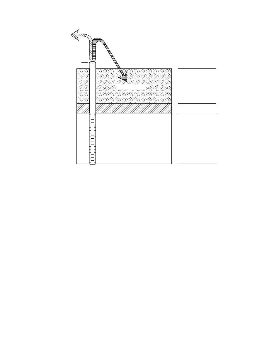
32
MODFLOW-2000—Documentation of Packages for Simulating Evapotranspiration with a
Segmented Function (ETS1) and Drains with Return Flow (DRT1)
Figure 5.-- Conceptual model of the use of the DRT1 Package to simulate the return flow of a portion of
discharge from a flowing well. When the head in the drain-return cell is higher than the drain elevation,
water discharges from the ground-water system; a user-specified proportion of this discharge returns to
the ground-water system at the recipient cell.
Recipient cell
Drain
elevation
Drain-return cell
Surficial aquifer
Confining unit
Confined aquifer
(head in cell is
higher than drain
elevation)
Water permanently
removed from the
ground-water
system
Water returned to the
ground-water system
as return flow to the
recipient cell
Flowing well completed
in the confined aquifer
When the DRT1 Package is used, the volumetric budget written to the LIST output file includes DRT1-
Package entries in both the “IN” and “OUT” sections. The volume and rate of flow listed for the DRT1 Package in
the “IN” section include the return flow to all recipient cells. The volume and rate of flow listed in the “OUT”
section include all water flowing out of all drain-return cells, and so include both the water permanently removed
from the ground-water system and the water returned to the ground-water system as return flow.
The DRT1 Package supports the use of parameters as discussed in Harbaugh and others (2000) and Hill and
others (2000). Drain-return parameters control the hydraulic conductance of drain-return features. Drain-return
features can be specified using parameters, without using parameters, or using a combination of the two methods.
More than one drain-return feature may be specified at a single cell for the same stress period, with or
without the use of parameters. The need for more than one such feature could arise if multiple flowing wells with
differing well-head elevations are located in a cell or if return flow is to be directed to more than one recipient cell.
Hill and others (2000) describe how to construct input files so that flow observations for different features in the
same cell are interpreted by the program as intended by the user.
Input Instructions for the Drain Return Package
Input to the DRT1 Package is read from the file that has type “DRT” in the name file. Optional variables are
shown in brackets. All variables are free format if the option “FREE” is specified in the Basic Package input file;
otherwise, the non-optional variables have 10-character fields and the optional variables are free format.

Drain Return Package
33
FOR EACH SIMULATION
0. [#Text]
Item 0 is optional -- “#” must be in column 1. Item 0 can be repeated as many times as desired.
1. MXADRT IDRTCB NPDRT MXL [Option]
2. [PARNAM PARTYP Parval NLST]
3. Layer Row Column Elevation Condfact [LayR RowR ColR Rfprop] [xyz]
NLST repetitions of Item 3 records are required; they are read by module ULSTRD (Harbaugh and others,
2000). (SFAC of the ULSTRD utility module applies to Condfact.)
Repeat Items 2 and 3 for each parameter to be defined (that is, NPDRT times). Items 2 and 3 are omitted if
NPDRT = 0.
FOR EACH STRESS PERIOD
4. ITMP NP
5. Layer Row Column Elevation Cond [LayR RowR ColR Rfprop] [xyz]
ITMP repetitions of Item 5 records are read by module ULSTRD (Harbaugh and others, 2000) if ITMP > 0.
(SFAC of the ULSTRD utility module applies to Cond). Item 5 is not read if ITMP
≤
0.
6. Pname
(Item 6 is repeated NP times. It is not read if NP
≤
0.)
Explanation of Variables Read by the Drain Return Package
Text—is a character variable (79 characters) that starts in column 2. Any characters can be included in Text. The
“#” character must be in column 1. Lines beginning with “#” are restricted to these first lines of the input file. Text
is written to the LIST output file when the input file is read.
MXADRT—is the maximum number of drain-return cells in use during any stress period, including those defined
using parameters. Recipient cells are not included in MXADRT.
IDRTCB—is a flag and a unit number.
If IDRTCB > 0, it is the unit number to which DRT1-Package cell-by-cell flow terms will be written when
“SAVE BUDGET” or a non-zero value for ICBCFL is specified in Output Control (Harbaugh and oth-
ers, 2000). IDRTCB must be a unit number associated with a file listed with type “DATA(BINARY)”
or “DATAGLO(BINARY)” in the name file.
If IDRTCB = 0, DRT1-Package cell-by-cell flow terms will not be written.
If IDRTCB < 0, drain leakage for each drain-return cell and return flow to each recipient cell will be writ-
ten to the LIST file when “SAVE BUDGET” or a non-zero value for ICBCFL is specified in Output
Control.
NPDRT—is the number of drain-return parameters.
MXL—is the maximum number of drain-return cells that will be defined using parameters. Recipient cells are not
included in MXL.
Option—is an optional list of character values.
“AUXILIARY abc” or “AUX abc”—defines an auxiliary variable (Harbaugh and McDonald, 1996a, p. 9,
item 4), named “abc,” which will be read for each drain as part of items 3 and 5. Up to five variables
can be specified, each of which must be preceded by “AUXILIARY” or “AUX.” These variables will
not be used by the Ground-Water Flow Process, but they will be available for use by other processes.
The auxiliary variable values will be read after the Cond variable.

34
MODFLOW-2000—Documentation of Packages for Simulating Evapotranspiration with a
Segmented Function (ETS1) and Drains with Return Flow (DRT1)
“CBCALLOCATE” or “CBC”—indicates that memory should be allocated to store cell-by-cell flow for
each drain in order to make these flows available for use in other packages.
“RETURNFLOW”—activates the return-flow option of the DRT1 Package. If “RETURNFLOW” is listed
as an option, LayR, and, optionally, RowR, ColR, and Rfprop are read from items 3 and(or) 5.
PARNAM—is the name of a parameter to be defined. This name can consist of 1 to 10 characters and is not case
sensitive. That is, any combination of the same characters with different case will be equivalent.
PARTYP—is the type of parameter to be defined. For the DRT1 Package, the only allowed parameter type is
“DRT,” which defines values of the drain hydraulic conductance.
Parval—is the parameter value. This parameter value may be overridden by a value in the Sensitivity Process
input file or by a value generated by the Parameter-Estimation Process.
NLST—is the number of drain-return cells included in the parameter.
Layer—is the layer number of the cell containing the drain.
Row—is the row number of the cell containing the drain.
Column—is the column number of the cell containing the drain.
Elevation—is the elevation of the drain.
Condfact—is the factor used to calculate drain hydraulic conductance from the parameter value. The conductance
(L
2
/T) is the product of Condfact and the parameter value.
LayR—is a flag and, if greater than 0, a layer number. If auxiliary variables are being read, LayR must be greater
than zero, so that RowR, ColR, and Rfprop are read. LayR is not read if “RETURNFLOW” is not listed as an
option in item 1.
If LayR > 0, it is the layer number of the recipient cell.
If LayR = 0, there is no return flow for the drain cell, and RowR, ColR, and Rfprop are not read.
RowR—is the row number of the recipient cell. RowR is not read if “RETURNFLOW” is not listed as an option
in item 1.
ColR—is the column number of the recipient cell. ColR is not read if “RETURNFLOW” is not listed as an option
in item 1.
Rfprop—is the return-flow proportion. Valid values are in the range 0.0 to 1.0, inclusive. Rfprop is the proportion
of the drain flow, if any, calculated for the drain-return cell simulated as returning to the recipient cell. If Rfprop
equals 0.0, the return-flow capability is deactivated for the cell. Rfprop is not read if “RETURNFLOW” is not
listed as an option in item 1.
[xyz]—is up to five auxiliary variables for a drain-return cell that have been defined in item 1. The auxiliary vari-
ables must be present in each repetition of items 3 and 5 record if they are defined in item 1.
ITMP—is a flag and a counter.
If ITMP < 0, non-parameter drain-return data from the last stress period will be reused.
If ITMP
≥
0, ITMP will be the number of non-parameter drain-return cells read for the current stress
period.
NP—is the number of drain-return parameters in use in the current stress period.
Cond—is the hydraulic conductance of the interface between the aquifer and the drain.
Pname—is the name of a parameter being used in the current stress period. NP parameter names will be read.

Drain Return Package
35
Flow Observations Using the Drain Return Package
The concept of flow observations and related equations are presented in chapter 4 of Hill and others (2000).
The method for specifying flow observations for features simulated using the DRT1 Package is nearly identical to
the method used for features simulated using the DRN Package (Hill and others, 2000). For each observation
specified, MODFLOW-2000 calculates a simulated equivalent, which can be compared to the user-specified
observed value. The simulated equivalents calculated by the DRT1 Package include the flow from the drain-return
cells and are not adjusted for any return flow to recipient cells. The differences between use of the DRN Package
and use of the DRT1 Package to specify flow observation are: (1) the file type “DTOB” is used in the name file for
the DRT1 Package instead of “DROB,” which is used for the DRN Package; and (2) the variable names differ.
When more than one drain-return feature is specified at the same cell in the same stress period, care must be
taken to ensure that flow observations are associated with the correct feature. Hill and others (2000) provide
instructions for preparing an input file to address this situation.
Input Instructions for Flow Observations
Input for the file used to specify flow observations using the DRT1 Package is read from a file that is speci-
fied with “DTOB” as the file type listed in the name file.
0. [#Text]
Item 0 is optional and can include as many lines as desired. Each line needs to begin with the “#” character
in the first column.
1. NQDT NQCDT NQTDT
(free format)
2. TOMULTDT EVFDT IOWTQDT
(free format)
Read items 3, 4, and 5 for each of NQDT groups of cells for which flow observations are to be specified for
features simulated with the DRT1 Package.
3. NQOBDT NQCLDT
(free format)
Read item 4 for each of NQOBDT observation times for this group of cells. STATISTIC and STAT-FLAG
are ignored if IOWTQDT > 0.
4. OBSNAM IREFSP TOFFSET HOBS STATISTIC STAT-FLAG PLOT-SYMBOL
(free format)
Read item 5 for each cell in this group; the number of cells equals the absolute value of NQCLDT from
item 3.
5. Layer Row Column Factor
(free format)
Read items 6 and 7 if IOWTQDT > 0.
6. FMTIN IPRN
(free format)
7. WTQ(1,1), WTQ(1,2), WTQ(1,3), ... , WTQ(1,NQTDT)
(format: FMTIN)
WTQ(2,1), WTQ(2,2), WTQ(2,3), ... , WTQ(2,NQTDT)
...
WTQ(NQTDT,1), WTQ(NQTDT,2), WTQ(NQTDT,3), ... , WTQ(NQTDT,NQTDT)
Explanation of Variables for Flow Observations
Text—is a character variable (79 characters) that starts in column 2. Any characters can be included in Text. The
“#” character must be in column 1. Lines beginning with “#” are restricted to these first lines of the input file. Text
is written to the LIST output file when the input file is read and provides an opportunity for the user to include
information about the model both in the input file and the associated output file.
NQDT—is the number of cell groups for which drain-return flow observations are listed. A group consists of the
drain-return cells needed to represent one flow measurement. Recipient cells are not included in NQDT.
NQCDT—is greater than or equal to the total number of drain-return cells in all cell groups. NQCDT must be
greater than or equal to the sum of all |NQCLDT|. Recipient cells are not included in NQCDT.

36
MODFLOW-2000—Documentation of Packages for Simulating Evapotranspiration with a
Segmented Function (ETS1) and Drains with Return Flow (DRT1)
NQTDT—is the total number of drain-return observations for all cell groups. NQTDT must equal the sum of all
NQOBDT, which are specified in repetitions of item 3 in the DTOB input file.
TOMULTDT—is the time-offset multiplier for drain-return observations [-- or T/T]. The product of TOMULTDT
and TOFFSET must produce a time value in units consistent with other model input. TOMULTDT can be dimen-
sionless or can be used to convert the units of TOFFSET to the time unit used in the simulation.
EVFDT—is the error variance multiplier for observations represented by the DRT1 Package, and is used to calcu-
late the weights as described below in the explanation of STATISTIC. EVFDT makes it easy to change the
weights uniformly for all flow observations represented using the DRT1 Package.
IOWTQDT—is a flag that indicates that the variance-covariance matrix on drain-return flow observations is to be
read into array WTQ of item 7. If IOWTQDT equals zero, weights are calculated using STATISTIC of item 4; if it
is greater than zero, items 6 and 7 are read and used to calculate the weights.
NQOBDT—is the number of times at which flows are observed for the group of cells.
NQCLDT—is a flag, and the absolute value of NQCLDT is the number of drain-return cells in the group. If
NQCLDT is less than zero, FACTOR = 1.0 for all cells in the group. Recipient cells are not included in
NQCLDT.
OBSNAM—is a string of 1 to 12 non-blank characters used to identify the observation.
IREFSP—is the reference stress period to which observation times are referenced. The reference point is the
beginning of the stress period.
TOFFSET—is the time offset of the observation from the beginning of stress period IREFSP [T]. TOFFSET must
be in units such that the product of TOMULTDT and TOFFSET is in time units consistent with other model input.
TOFFSET and TOMULTDT from the DTOB file and values of PERLEN, NSTP, and TSMULT from the DIS file
(Harbaugh and others, 2000) are used to determine the stress period, time step, and time during the time step for
the observation. To specify that an observation is for a steady-state model solution, specify IREFSP as the stress-
period number of the steady-state stress period, and specify TOFFSET such that TOMULTDT
×
TOFFSET is less
than or equal to PERLEN for the stress period; if PERLEN is zero, set TOFFSET to zero. If the observation falls
within a time step, the simulated equivalent is calculated by linearly interpolating between values for the begin-
ning and end of the time step. If the first stress period is transient and the observation falls within the first time
step, the simulated equivalent from the end of the time step is used because no flow from the beginning of the time
step is available for interpolation.
HOBS—is the observed drain-return-boundary flow [L
3
/T]. For the DRT1 Package, only negative values of
HOBS are expected. Negative values indicate flow out of the ground-water system.
STATISTIC—is the value from which the weight for the observation is calculated as determined using STAT-
FLAG. STATISTIC is ignored if IOWTQDT is greater than zero, in which case WTQ of item 7 is used to define
the weighting.
STAT-FLAG—is a flag identifying what STATISTIC is and how the weight is calculated. STAT-FLAG is ignored
if IOWTQDT is greater than zero.
STAT-FLAG = 0, STATISTIC is a scaled variance [(L
3
/T)
2
], weight = 1/(STATISTIC
×
EVFDT)
STAT-FLAG = 1, STATISTIC is a scaled standard deviation [L
3
/T], weight = 1/(STATISTIC
2
×
EVFDT)
STAT-FLAG = 2, STATISTIC is a scaled coefficient of variation [dimensionless], weight = 1/[(STATISTIC
×
HOBS)
2
×
EVFDT]
Drain Return Package
37
PLOT-SYMBOL—is an integer that will be written to output files intended for graphical analysis to allow control
of the symbols used when plotting data (Hill and others, 2000).
LAYER—is the layer index of a drain-return cell included in the cell group.
ROW—is the row index of a drain-return cell included in the cell group.
COLUMN—is the column index of a drain-return cell included in the cell group.
FACTOR—is the portion of the simulated drain flow in the cell that is included in the total simulated drain flow
for this cell group (f
n
of eq. 9 in Hill and others, 2000).
FMTIN—is the Fortran format to be used in reading each line of the variance-covariance matrix used to calculate
the weighting. The format needs to be enclosed in parentheses and needs to accommodate real numbers.
IPRN—is a flag identifying the format in which the variance-covariance matrix is to be printed. If IPRN is less
than zero, the matrix is not printed. Permissible values of IPRN and corresponding formats are
:
WTQ—is an NQTDT by NQTDT array containing the variance-covariance matrix on drain-return flow observa-
tions [(L
3
/T)
2
]. For elements WTQ(I,J), if I
≠
J, WTQ(I,J) is the covariance between observations I and J; if I = J,
WTQ(I,J) is the variance of observation I. Note that the variance-covariance matrix is symmetric, but the entire
matrix (upper and lower parts) must be entered.
DRT1 Example Problem
A simple example problem was devised to demonstrate that the DRT1 Package correctly calculates flow out
of a drain-return cell and into a recipient cell when the RETURNFLOW option is selected. For this problem, a
grid of 11 rows by 11 columns in one layer was used to simulate an unconfined aquifer with a uniform base eleva-
tion of 0 ft. All row and column widths were 100 ft. All cells in column 1 had a specified head of 50 ft, and all
cells in column 11 had a specified head of 100 ft. Hydraulic conductivity of the aquifer material was 0.05 ft/d, and
the system was modeled in steady state. A drain was simulated in row 5, column 8, and 40 percent of the flow
from the drain was assumed to return to the ground-water system in row 7, column 3 (fig. 6). The drain elevation
was 60 ft and the conductance of the drain was 2 ft
2
/d. This system was simulated with the DRT1 Package for one
simulation and with the DRN and WEL Packages (Harbaugh and others, 2000) for a second simulation. The input
files for these simulations are listed in Appendix B.
For the simulation using the DRT1 Package, a drain-return feature was defined in the cell in row 5,
column 8. The corresponding recipient cell was specified in row 7, column 3. The return-flow proportion was
specified as 0.4. Results of the model run showed that flow out of the ground-water system at the drain-return cell
was 45.2126 ft
3
/d. Note that, in general, model results would be presented with no more significant digits than are
supported by the input data; however, for this demonstration of model accuracy, all digits shown in the LIST file
Output requires more than 80 columns
Output requires 80 columns or less
IPRN
Format
IPRN
Format
1
10G12.3
6
5G12.3
2
10G12.4
7
5G12.4
3
9G12.5
8
5G12.5
4
8G13.6
9
4G13.6
5
8G14.7
10
4G14.7

38
MODFLOW-2000—Documentation of Packages for Simulating Evapotranspiration with a
Segmented Function (ETS1) and Drains with Return Flow (DRT1)
are reported. Flow into the system at the recipient cell was 18.0850 ft
3
/d, which equals 40 percent of the flow out
of the system at the drain-return cell. The LIST output file generated by this simulation is in Appendix B. When
the DRT1 Package is used to simulate the system, the ratio of flow into the system at the recipient cell to flow out
of the system at the drain-return cell always would equal 0.40, even if calculated head at the drain-return cell
changes with changing stresses.
For the simulation using the DRN and WEL Packages, a drain was simulated in row 5, column 8, and an
injection well was simulated in row 7, column 3. The injection rate was specified as 18.0850 ft
3
/d to agree with the
results from the simulation that used the DRT1 Package. Flow out of the ground-water system at the drain was
calculated as 45.2125 ft
3
/d, matching the outflow obtained using the DRT1 Package. The calculated head distribu-
tion and volumetric budget for this simulation are listed in Appendix B. The head distribution was identical to that
obtained with the DRT1 Package, and the volumetric budgets were identical within round-off error. Note that if
different stresses were applied to the system and were to result in a different calculated head at the drain cell, the
user would need to manually change the specified injection rate to maintain the assumed 40-percent ratio of inflow
to outflow.
1
2
3
4
5
6
7
8
9
10
11
1
2
3
4
5
6
7
8
9
10
11
Column number
Row number
C
C
C
C
C
C
C
C
C
C
C
C
C
C
C
C
C
C
C
C
C
C
I
D
Constant-head cell
Drain or drain-return cell
Injection well or recipient cell
C
D
I
Figure 6.-- Location of features simulated in the DRT1 example problem.

Drain Return Package
39
Module Documentation for the Drain Return Package
The DRT1 Package is composed of 14 modules. Five of these are primary modules that are part of the
Ground-Water Flow Process. Four are primary modules that are part of the Observation Process. One is a primary
module that is part of the Sensitivity Process. Primary modules are called directly from the main program unit. In
addition, the DRT1 Package includes two secondary modules that are part of the Ground-Water Flow Process and
two secondary modules that are part of the Observation Process. Secondary modules are called from other
modules. The 14 modules are:
GWF1DRT1AL—Reads options and allocates memory for data arrays. GWF1DRT1AL is a primary module of
the Ground-Water Flow Process and is in source-code file gwf1drt1.f.
GWF1DRT1RQ—Reads drain-return parameter definitions. GWF1DRT1RQ is a primary module of the Ground-
Water Flow Process and is in source-code file gwf1drt1.f.
GWF1DRT1RP—Reads drain-return cell data and, if DRT parameters are defined, performs substitution using
parameter values. GWF1DRT1RP is a primary module of the Ground-Water Flow Process and is in source-code
file gwf1drt.f.
GWF1DRT1FM—Formulates terms needed to solve the ground-water flow equation and adds them to the head-
coefficient array (HCOF) and to the right-hand side array (RHS). GWF1DRT1FM is a primary module of the
Ground-Water Flow Process and is in source-code file gwf1drt1.f.
GWF1DRT1BD—Computes flow rates simulated as flow from drain-return cells and to recipient cells and writes
cell-by-cell flow rates if that option is selected. GWF1DRT1BD is a primary module of the Ground-Water Flow
Process and is in source-code file gwf1drt1.f.
SGWF1DRT1LR—Reads and prints a list of drain-return cell data. SGWF1DRT1LR is a secondary module of
the Ground-Water Flow Process and in source-code file gwf1drt1.f.
SGWF1DRT1LS—Reads a DRT parameter name and performs substitution for associated drain-return cells using
the current parameter value. SGWF1DRT1LS is a secondary module of the Ground-Water Flow Process and is in
source-code file gwf1drt1.f.
OBS1DRT1AL—Reads data from the DTOB file regarding numbers of observations at drain-return cells and
allocates memory. OBS1DRT1AL is a primary module of the Observation Process and is in source-code file
obs1drt1.f.
OBS1DRT1RP—Reads and checks flow-observation data for drain-return cells. OBS1DRT1RP is a primary
module of the Observation Process and is in source-code file obs1drt1.f.
OBS1DRT1FM—Calculates simulated equivalents for flow observations at drain-return cells. OBS1DRT1FM is a
primary module of the Observation Process and is in source-code file obs1drt1.f.
OBS1DRT1DR—Calculates sensitivities for flow observations at drain-return cells. OBS1DRT1DR is a primary
module of the Observation Process and is in source-code file obs1drt1.f.
SOBS1DRT1OH—Calculates and prints weighted residuals for flow observations at drain-return cells.
SOBS1DRT1OH is a secondary module of the Observation Process and is in source-code file obs1drt1.f.

40
MODFLOW-2000—Documentation of Packages for Simulating Evapotranspiration with a
Segmented Function (ETS1) and Drains with Return Flow (DRT1)
SOBS1DRT1QC—Populates QCLS array with Condfact from parameter definition for one DRT parameter.
SOBS1DRT1QC is a secondary module of the Observation Process and is in source-code file obs1drt1.f.
SEN1DRT1FM—Formulates terms needed to solve the sensitivity equation and adds them to the right-hand side
array (RHS). SEN1DRT1FM is a primary module of the Sensitivity Process and is in source-code file sen1drt1.f.
Module GWF1DRT1AL
Narrative for Module GWF1DRT1AL
This primary module reads package options from item 1 of the DRT1 input file and allocates space in the
RX and IR arrays (Harbaugh and others, 2000). Output is written to the LIST file.
1.
Print a message identifying the DRT1 Package.
2.
Read and print comment lines (item 0) introduced with the “#” character.
3.
Read maximum number of DRT1 cells that can be active at one time (MXADRT), the unit number for cell-
by-cell flow terms (IDRTCB), the number of parameters (NPDRT), the maximum number of drain-return
cells to be defined using parameters (MXL), and any package options from item 1. Print messages related
to number of cells, number of parameters, options and, if IDRTCB is greater than zero, the unit number.
4.
Allocate space in the RX array for the DRTF array.
5.
Print a message showing amount of storage required by the DRT1 Package.
Listing for Module GWF1DRT1AL
SUBROUTINE GWF1DRT1AL(ISUM,LCDRTF,MXDRT,NDRTCL,IN,IOUT,IDRTCB,
& NDRTVL,IDRTAL,IFREFM,NPDRT,IDRTPB,NDRTNP,
& IDRTFL)
C
C-----VERSION 20000620 ERB
C ******************************************************************
C ALLOCATE ARRAY STORAGE FOR DRAINS AND RETURN FLOWS
C ******************************************************************
C
C SPECIFICATIONS:
C ------------------------------------------------------------------
COMMON /DRTCOM/DRTAUX(5)
CHARACTER*16 DRTAUX
CHARACTER*200 LINE
C ------------------------------------------------------------------
C
C1------IDENTIFY PACKAGE AND INITIALIZE NDRTCL.
WRITE(IOUT,1)IN
1 FORMAT(1X,/
&1X,'DRT1 -- DRAIN RETURN PACKAGE, VERSION 1, 5/2/2000',/,
&' INPUT READ FROM UNIT',I3)
NDRTCL=0
NDRTNP=0
IDRTFL=0
C
C2------READ MAXIMUM NUMBER OF DRAINS AND UNIT OR FLAG FOR
C2------CELL-BY-CELL FLOW TERMS.
C READ COMMENTS (ITEM 0)
CALL URDCOM(IN,IOUT,LINE)
C READ ITEM 1
IF (IFREFM.EQ.0) THEN
READ(LINE,'(4I10)') MXADRT,IDRTCB,NPDRT,MXL

Drain Return Package
41
LLOC=21
ELSE
LLOC=1
CALL URWORD(LINE,LLOC,ISTART,ISTOP,2,MXADRT,R,IOUT,IN)
CALL URWORD(LINE,LLOC,ISTART,ISTOP,2,IDRTCB,R,IOUT,IN)
CALL URWORD(LINE,LLOC,ISTART,ISTOP,2,NPDRT,R,IOUT,IN)
CALL URWORD(LINE,LLOC,ISTART,ISTOP,2,MXL,R,IOUT,IN)
ENDIF
WRITE(IOUT,3) MXADRT
3 FORMAT(1X,'MAXIMUM OF',I5,
&' ACTIVE DRAINS WITH RETURN FLOW AT ONE TIME')
IF (IDRTCB.LT.0) WRITE(IOUT,7)
7 FORMAT(1X,'CELL-BY-CELL FLOWS WILL BE PRINTED WHEN ICBCFL NOT 0')
IF (IDRTCB.GT.0) WRITE(IOUT,8) IDRTCB
8 FORMAT(1X,'CELL-BY-CELL FLOWS WILL BE SAVED ON UNIT',I3)
C
IF (NPDRT.GT.0) THEN
WRITE(IOUT,9) NPDRT,MXL
9 FORMAT(1X,I5,' Named Parameters ',I5,' List entries')
ELSE
WRITE(IOUT,'(A)') ' No named parameters'
END IF
C3------READ AUXILIARY VARIABLES AND CBC ALLOCATION OPTION.
IDRTAL=0
NAUX=0
10 CALL URWORD(LINE,LLOC,ISTART,ISTOP,1,N,R,IOUT,IN)
IF (LINE(ISTART:ISTOP).EQ.'CBCALLOCATE' .OR.
& LINE(ISTART:ISTOP).EQ.'CBC') THEN
IDRTAL=1
WRITE(IOUT,11)
11 FORMAT(1X,'MEMORY IS ALLOCATED FOR CELL-BY-CELL BUDGET TERMS')
GOTO 10
ELSEIF(LINE(ISTART:ISTOP).EQ.'AUXILIARY' .OR.
& LINE(ISTART:ISTOP).EQ.'AUX') THEN
CALL URWORD(LINE,LLOC,ISTART,ISTOP,1,N,R,IOUT,IN)
IF (NAUX.LT.5) THEN
NAUX=NAUX+1
DRTAUX(NAUX)=LINE(ISTART:ISTOP)
WRITE(IOUT,12) DRTAUX(NAUX)
12 FORMAT(1X,'AUXILIARY DRAIN-RETURN FLOW VARIABLE: ',A)
ENDIF
GOTO 10
ELSEIF (LINE(ISTART:ISTOP).EQ.'RETURNFLOW') THEN
IDRTFL=4
WRITE(IOUT,13)
GOTO 10
13 FORMAT(1X,'RETURN FLOW OPTION IS SELECTED')
ENDIF
IF (IDRTAL.EQ.1 .AND. IDRTFL.EQ.4) IDRTAL = 2
NDRTVL=5+NAUX+IDRTAL+IDRTFL
C
C4------ALLOCATE SPACE IN THE RX ARRAY FOR THE DRTF ARRAY.
IDRTPB=MXADRT+1
MXDRT=MXADRT+MXL
ISOLD=ISUM
LCDRTF=ISUM
ISUM=ISUM+NDRTVL*MXDRT
C
C5------PRINT AMOUNT OF SPACE USED BY DRAIN PACKAGE.
ISP=ISUM-ISOLD
WRITE (IOUT,14)ISP
14 FORMAT(1X,I10,' ELEMENTS IN RX ARRAY ARE USED BY DRT')
C
C6------RETURN.
RETURN
END

42
MODFLOW-2000—Documentation of Packages for Simulating Evapotranspiration with a
Segmented Function (ETS1) and Drains with Return Flow (DRT1)
List of Variables for Module GWF1DRT1AL
Module GWF1DRT1RQ
Narrative for Module GWF1DRT1RQ
This primary module reads parameter definitions (items 2 and 3) from the DRT1 input file. Output is written
to the GLOBAL file.
1.
Print a message indicating how many drain-return parameters are being used.
2.
For each drain-return parameter, call a utility and a secondary DRT1 module to read the parameter definition.
The utility reads item 2 and prints the parameter name, type, value, and number of list entries used to
define the parameter. The secondary module reads item 3 and prints the list entries, including drain-return
cell location, drain elevation, a factor, recipient-cell location, and return-flow proportion.
Variable
Range
Definition
DRTAUX
Package
Auxiliary-variable names
IDRTAL
Package
Indicator for saving cell-by-cell budget terms
IDRTCB
Package
Indicator and unit number for writing cell-by-cell flows
IDRTFL
Package
Indicator for return-flow option
IDRTPB
Package
First position in DRTF array used for storing parameter data
IFREFM
Global
Flag indicating if variables are to be read in free format
IN
Module
Unit number for input file
IOUT
Global
Unit number of LIST output file
ISOLD
Module
ISUM value before allocation
ISP
Module
Number of elements allocated in RX array
ISTART
Module
Starting position of parsed word
ISTOP
Module
Ending position of parsed word
ISUM
Module
Pointer used to keep track of position in RX
LCDRTF
Package
Position in RX of first element of DRTF
LINE
Module
Contents of one line read from input file
LLOC
Module
Pointer used to keep track of position in LINE
MXADRT
Package
Maximum number of drain-return cells that can be active in a stress period
MXDRT
Package
Dimensioning variable for DRTF
MXL
Module
Maximum number of drain-return cells that will be defined using parameters
N
Module
Dummy integer variable
NAUX
Module
Number of auxiliary variables
NDRTCL
Package
Number of drain-return cells used in a stress period
NDRTNP
Package
Number of non-parameter drain-return cells in use during a stress period
NDRTVL
Package
Dimensioning variable for DRTF
NPDRT
Package
Number of drain-return parameters
R
Module
Dummy real variable

Drain Return Package
43
Listing for Module GWF1DRT1RQ
SUBROUTINE GWF1DRT1RQ(IN,IOUT,NDRTVL,IDRTAL,NCOL,NROW,NLAY,NPDRT,
& DRTF,IDRTPB,MXDRT,IFREFM,ITERP,IDRTFL)
C
C-----VERSION 20000620 ERB
C ******************************************************************
C READ DRAIN-RETURN PARAMETERS
C ******************************************************************
C
C SPECIFICATIONS:
C ------------------------------------------------------------------
DIMENSION DRTF(NDRTVL,MXDRT)
COMMON /DRTCOM/DRTAUX(5)
CHARACTER*16 DRTAUX
C ------------------------------------------------------------------
C
C-------READ NAMED PARAMETERS.
IF (ITERP.EQ.1) WRITE(IOUT,500) NPDRT
500 FORMAT(1X,//1X,I5,' Drain-return parameters')
IF (NPDRT.GT.0) THEN
NAUX=NDRTVL-5-IDRTAL-IDRTFL
LSTSUM=IDRTPB
DO 10 K=1,NPDRT
LSTBEG=LSTSUM
C READ ITEM 2
CALL UPARLSTRP(LSTSUM,MXDRT,IN,IOUT,IP,'DRT','DRT',ITERP)
NLST=LSTSUM-LSTBEG
C READ ITEM 3
CALL SGWF1DRT1LR(NLST,DRTF,LSTBEG,NDRTVL,MXDRT,IDRTAL,IN,IOUT,
& DRTAUX,5,NAUX,IFREFM,NCOL,NROW,NLAY,ITERP,
& IDRTFL)
10 CONTINUE
ENDIF
C
C6------RETURN
RETURN
END
List of Variables for Module GWF1DRT1RQ
Variable
Range
Definition
DRTAUX
Package
Auxiliary-variable names
DRTF
Package
Drain-return cell data
IDRTAL
Package
Indicator for saving cell-by-cell budget terms
IDRTFL
Package
Indicator for return-flow option
IDRTPB
Package
First position in DRTF array used for storing parameter data
IFREFM
Global
Flag indicating if variables are to be read in free format
IN
Module
Unit number of input file
IOUT
Global
Unit number of GLOBAL output file
IP
Module
Parameter number
ITERP
Global
Parameter-estimation iteration number
K
Module
Index for parameters
LSTBEG
Module
First position in DRTF of a list of parameter-controlled drain-return cells
LSTSUM
Module
Position in DRTF following a list of parameter-controlled drain-return cells
44
MODFLOW-2000—Documentation of Packages for Simulating Evapotranspiration with a
Segmented Function (ETS1) and Drains with Return Flow (DRT1)
Module GWF1DRT1RP
Narrative for Module GWF1DRT1RP
This primary module, for each stress period, reads items 4 through 6 of the DRT1 input file and prepares
data. Output is written to the LIST file.
1.
Read ITMP and, if DRT1 parameters are defined, NP from item 4 of the DRT1 file.
2.
Determine how many auxiliary variables need to be read.
3.
Determine the number of non-parameter drain-return cells to be read. If ITMP > 0, this number is ITMP.
4.
If non-parameter drain-return cells are to be read, call a secondary module to read data for them from item 5.
5.
If NP > 0, DRT1 parameters are active this stress period; so, for each of NP parameters, call a secondary
module to read the name from item 6 and prepare data using the current parameter values.
6.
Determine how many of the drain-return cells can return a portion of the flow to a recipient cell. Drain-return
cells that have a non-zero layer index can return flow to a recipient cell.
7.
Print a message showing how many drain-return cells are active this stress period.
Listing for Module GWF1DRT1RP
SUBROUTINE GWF1DRT1RP(DRTF,NDRTCL,MXDRT,IN,IOUT,NDRTVL,IDRTAL,
& IFREFM,NCOL,NROW,NLAY,NDRTNP,NPDRT,IDRTPB,
& IDRTFL,NRFLOW)
C
C-----VERSION 20000620 ERB
C ******************************************************************
C READ DRAIN HEAD, CONDUCTANCE AND BOTTOM ELEVATION. IF THE
C RETURNFLOW OPTION IS SELECTED, READ RECIPIENT CELL AND PROPORTION.
C ******************************************************************
C
C SPECIFICATIONS:
C ------------------------------------------------------------------
DIMENSION DRTF(NDRTVL,MXDRT)
COMMON /DRTCOM/DRTAUX(5)
CHARACTER*16 DRTAUX
C ------------------------------------------------------------------
C
C1------READ ITMP (NUMBER OF DRAINS OR FLAG TO REUSE DATA) AND
MXDRT
Package
Dimensioning variable for DRTF
NAUX
Module
Number of auxiliary variables
NCOL
Global
Number of columns in model grid
NDRTVL
Package
Dimensioning variable for DRTF
NLAY
Global
Number of layers in model grid
NLST
Module
Number of drain-return cells in list
NPDRT
Package
Number of drain-return parameters
NROW
Global
Number of rows in model grid
Variable
Range
Definition

Drain Return Package
45
C1------NUMBER OF PARAMETERS.
IF (NPDRT.GT.0) THEN
IF (IFREFM.EQ.0) THEN
READ(IN,'(2I10)') ITMP,NP
ELSE
READ(IN,*) ITMP,NP
ENDIF
ELSE
NP=0
IF (IFREFM.EQ.0) THEN
READ(IN,'(I10)') ITMP
ELSE
READ(IN,*) ITMP
ENDIF
ENDIF
C
C------CALCULATE SOME CONSTANTS
NAUX=NDRTVL-5-IDRTAL-IDRTFL
C
C2------DETERMINE THE NUMBER OF NON-PARAMETER DRAIN-RETURN CELLS.
IF (ITMP.LT.0) THEN
WRITE(IOUT,7)
7 FORMAT(1X,/,
&' REUSING NON-PARAMETER DRAIN-RETURN CELLS FROM',
&' LAST STRESS PERIOD')
ELSE
NDRTNP=ITMP
ENDIF
C
C3------IF THERE ARE NEW NON-PARAMETER DRAIN-RETURN CELLS, READ THEM.
MXADRT=IDRTPB-1
IF (ITMP.GT.0) THEN
IF (NDRTNP.GT.MXADRT) THEN
WRITE(IOUT,500) NDRTNP,MXADRT
500 FORMAT(1X,/1X,'THE NUMBER OF ACTIVE DRT DRAINS (',I4,
& ') IS GREATER THAN MXADRT(',I4,')')
STOP
ENDIF
CALL SGWF1DRT1LR(NDRTNP,DRTF,1,NDRTVL,MXDRT,IDRTAL,IN,IOUT,
& DRTAUX,5,NAUX,IFREFM,NCOL,NROW,NLAY,1,IDRTFL)
ENDIF
NDRTCL=NDRTNP
C
C1C-----IF THERE ARE ACTIVE DRT PARAMETERS, READ THEM AND SUBSTITUTE
CALL PRESET('DRT')
IF (NP.GT.0) THEN
NREAD=NDRTVL-IDRTAL
DO 30 N=1,NP
CALL SGWF1DRT1LS(IN,IOUT,DRTF,NDRTVL,MXDRT,NREAD,MXADRT,
& NDRTCL,DRTAUX,5,NAUX,IDRTFL)
30 CONTINUE
ENDIF
C
C COUNT NUMBER OF DRAIN-RETURN CELLS THAT CAN HAVE RETURN FLOW
NRFLOW = 0
IF (IDRTFL.GT.0) THEN
DO 40 I=1,NDRTCL
IF (DRTF(6,I) .GT. 0.0) NRFLOW = NRFLOW + 1
40 CONTINUE
ENDIF
C
C3------PRINT NUMBER OF DRAIN-RETURN CELLS IN CURRENT STRESS PERIOD.
WRITE (IOUT,510) NDRTCL
510 FORMAT(1X,/1X,I5,' DRAIN-RETURN CELLS')
C
C8------RETURN.
RETURN
END

46
MODFLOW-2000—Documentation of Packages for Simulating Evapotranspiration with a
Segmented Function (ETS1) and Drains with Return Flow (DRT1)
List of Variables for Module GWF1DRT1RP
Module GWF1DRT1FM
Narrative for Module GWF1DRT1FM
This primary module adds terms to the finite-difference equations to account for loss of water from the
ground-water system through drain-return cells. Terms are added for recipient cells where a portion of the drain
flow is returned.
1.
For each cell in the drain-return cell list, do steps 2 through 5.
2.
If the cell is inactive or designated as constant-head, skip steps 3 through 5.
3.
If the head in the cell is at or below the drain elevation, skip steps 4 and 5.
Variable
Range
Definition
DRTAUX
Package
Auxiliary-variable names
DRTF
Package
Drain-return cell data
I
Module
Index for drain-return cells
IDRTAL
Package
Indicator for saving cell-by-cell budget terms
IDRTFL
Package
Indicator for return-flow option
IDRTPB
Package
First position in DRTF array used for storing parameter data
IFREFM
Global
Flag indicating if variables are to be read in free format
IN
Module
Unit number of input file
IOUT
Global
Unit number of LIST output file
ITMP
Module
Flag and number of non-parameter drain-return cells
MXADRT
Package
Maximum number of drain-return cells that can be active in a stress period
MXDRT
Package
Dimensioning variable for DRTF
N
Module
Index for DRT parameters active this stress period
NAUX
Module
Number of auxiliary variables
NCOL
Global
Number of columns in model grid
NDRTCL
Package
Number of drain-return cells used in a stress period
NDRTNP
Package
Number of non-parameter drain-return cells in use during current stress period
NDRTVL
Package
Dimensioning variable for DRTF
NLAY
Global
Number of layers in model grid
NP
Module
Number of DRT parameters active this stress period
NPDRT
Package
Number of drain-return parameters
NREAD
Module
Number of values to be substituted for each drain-return cell
NRFLOW
Package
Number of drain-return cells with a positive return-flow proportion
NROW
Global
Number of rows in model grid

Drain Return Package
47
4.
Add terms to HCOF and RHS for the drain-return cell to account for loss of water.
5.
If a recipient cell is specified to receive return flow, add term to RHS for the recipient cell to account for
return flow.
Listing for Module GWF1DRT1FM
SUBROUTINE GWF1DRT1FM(NDRTCL,MXDRT,DRTF,HNEW,HCOF,RHS,IBOUND,
& NCOL,NROW,NLAY,NDRTVL,IDRTFL)
C
C-----VERSION 20000620 ERB
C ******************************************************************
C ADD DRAIN-RETURN FLOW TO SOURCE TERMS FOR BOTH DRAIN-RETURN CELLS
C AND RECIPIENT CELLS
C ******************************************************************
C
C SPECIFICATIONS:
C ------------------------------------------------------------------
DOUBLE PRECISION HNEW,EEL
C
DIMENSION DRTF(NDRTVL,MXDRT),HNEW(NCOL,NROW,NLAY),
& RHS(NCOL,NROW,NLAY),IBOUND(NCOL,NROW,NLAY),
& HCOF(NCOL,NROW,NLAY)
C ------------------------------------------------------------------
C
C1------IF NDRTCL<=0 THERE ARE NO DRAINS. RETURN.
IF (NDRTCL.LE.0) RETURN
C
C2------PROCESS EACH CELL IN THE DRAIN-RETURN CELL LIST.
DO 100 L=1,NDRTCL
C
C3------GET COLUMN, ROW AND LAYER OF CELL CONTAINING DRAIN.
IL=DRTF(1,L)
IR=DRTF(2,L)
IC=DRTF(3,L)
C
C4-------IF THE CELL IS EXTERNAL SKIP IT.
IF (IBOUND(IC,IR,IL).LE.0) GOTO 100
C
C5-------IF THE CELL IS INTERNAL GET THE DRAIN DATA.
EL=DRTF(4,L)
EEL=EL
C
C6------IF HEAD IS LOWER THAN DRAIN THEN SKIP THIS CELL.
IF (HNEW(IC,IR,IL).LE.EEL) GOTO 100
C
C7------HEAD IS HIGHER THAN DRAIN. ADD TERMS TO RHS AND HCOF.
C=DRTF(5,L)
HCOF(IC,IR,IL)=HCOF(IC,IR,IL)-C
RHS(IC,IR,IL)=RHS(IC,IR,IL)-C*EL
IF (IDRTFL.GT.0) THEN
ILR = DRTF(6,L)
IF (ILR.NE.0) THEN
IRR = DRTF(7,L)
ICR = DRTF(8,L)
RFPROP = DRTF(9,L)
H = HNEW(IC,IR,IL)
RHS(ICR,IRR,ILR) = RHS(ICR,IRR,ILR)
& - RFPROP*C*(H-EL)
ENDIF
ENDIF
100 CONTINUE
C
C8------RETURN.
RETURN
END

48
MODFLOW-2000—Documentation of Packages for Simulating Evapotranspiration with a
Segmented Function (ETS1) and Drains with Return Flow (DRT1)
List of Variables for Module GWF1DRT1FM
Module GWF1DRT1BD
Narrative for Module GWF1DRT1BD
This primary module calculates rates and volumes of water removed from drain-return cells and returned
to recipient cells. Output is written to the LIST file and, optionally, to the unformatted file associated with unit
IDRTCB.
1.
If cell-by-cell flows will be saved as a list, write a header to the cell-by-cell output file.
2.
Initialize a buffer of all cell locations to zero.
3.
For each drain-return cell, do steps 4 through 11.
4.
If the cell is inactive, skip steps 5 through 11.
Variable
Range
Definition
C
Module
Hydraulic conductance of drain for a drain-return cell
DRTF
Package
Drain-return cell data
EEL
Module
Drain elevation for a drain-return cell
EL
Module
Drain elevation for a drain-return cell
H
Module
Hydraulic head at a drain-return cell
HCOF
Global
Head-coefficient array
HNEW
Global
Head
IBOUND
Global
Boundary-status indicator
IC
Module
Cell index of a drain-return cell
ICR
Module
Cell index of a recipient cell
IDRTFL
Package
Indicator for return-flow option
IL
Module
Layer index of a drain-return cell
ILR
Module
Layer index of a recipient cell
IR
Module
Row index of a drain-return cell
IRR
Module
Row index of a recipient cell
L
Module
Index for drain-return cells
MXDRT
Package
Dimensioning variable for DRTF
NCOL
Global
Number of columns in model grid
NDRTCL
Package
Number of drain-return cells used in a stress period
NDRTVL
Package
Dimensioning variable for DRTF
NLAY
Global
Number of layers in model grid
NROW
Global
Number of rows in model grid
RFPROP
Package
Return-flow proportion
RHS
Global
Right-hand side

Drain Return Package
49
5.
If the head in the cell is at or below the drain elevation, skip steps 6 through 11.
6.
Accumulate flow volume and rate out of the drain-return cell.
7.
Determine if a recipient cell is specified to receive return flow. If not, skip step 8.
8.
Accumulate flow volume and rate returned to the recipient cell.
9.
Write cell-by-cell flow rates to the LIST file, if requested.
10. Add rates to buffer at drain-return cell location and, if applicable, at recipient cell location.
11. Copy rates to DTRF array, if requested.
12. If requested, save cell-by-cell flow rates to the unformatted file associated with unit IDRTCB.
13. Move volumes, rates, and labels into arrays for printing budget.
14. Increment budget-term counter.
Listing for Module GWF1DRT1BD
SUBROUTINE GWF1DRT1BD(NDRTCL,MXDRT,VBNM,VBVL,MSUM,DRTF,DELT,HNEW,
& NCOL,NROW,NLAY,IBOUND,KSTP,KPER,IDRTCB,
& ICBCFL,BUFF,IOUT,PERTIM,TOTIM,NDRTVL,IDRTAL,
& IDRTFL,NRFLOW,IAUXSV)
C-----VERSION 20000620 ERB
C ******************************************************************
C CALCULATE VOLUMETRIC BUDGET FOR DRAIN-RETURN CELLS
C ******************************************************************
C
C SPECIFICATIONS:
C ------------------------------------------------------------------
COMMON /DRTCOM/DRTAUX(5)
CHARACTER*16 DRTAUX
CHARACTER*16 VBNM(MSUM),TEXT
DOUBLE PRECISION HNEW,HHNEW,EEL,CC,CEL,RATIN,RATOUT,QQ
C
DIMENSION VBVL(4,MSUM),DRTF(NDRTVL,MXDRT),HNEW(NCOL,NROW,NLAY),
& IBOUND(NCOL,NROW,NLAY),BUFF(NCOL,NROW,NLAY)
C
DATA TEXT /' DRAINS (DRT)'/
C ------------------------------------------------------------------
C
C1------INITIALIZE CELL-BY-CELL FLOW TERM FLAG (IBD) AND
C1------ACCUMULATORS (RATIN AND RATOUT).
ZERO=0.
RATIN=ZERO
RATOUT=ZERO
IBD=0
IF (IDRTCB.LT.0 .AND. ICBCFL.NE.0) IBD=-1
IF (IDRTCB.GT.0) IBD=ICBCFL
IBDLBL=0
C
C2------IF CELL-BY-CELL FLOWS WILL BE SAVED AS A LIST, WRITE HEADER.
IF (IBD.EQ.2) THEN
NAUX = NDRTVL - 5 - IDRTAL
IF (IAUXSV.EQ.0) NAUX = 0
CALL UBDSV4(KSTP,KPER,TEXT,NAUX,DRTAUX,IDRTCB,NCOL,NROW,NLAY,
& NDRTCL+NRFLOW,IOUT,DELT,PERTIM,TOTIM,IBOUND)
ENDIF
C
C3------CLEAR THE BUFFER.

50
MODFLOW-2000—Documentation of Packages for Simulating Evapotranspiration with a
Segmented Function (ETS1) and Drains with Return Flow (DRT1)
DO 30 IL=1,NLAY
DO 20 IR=1,NROW
DO 10 IC=1,NCOL
BUFF(IC,IR,IL)=ZERO
10 CONTINUE
20 CONTINUE
30 CONTINUE
C
C4------IF THERE ARE NO DRAIN-RETURN CELLS THEN DO NOT ACCUMULATE FLOW.
IF (NDRTCL.LE.0) GOTO 200
C
C5------LOOP THROUGH EACH DRAIN-RETURN CELL, CALCULATING FLOW.
DO 100 L=1,NDRTCL
C
C5A-----GET LAYER, ROW & COLUMN OF CELL CONTAINING DRAIN.
IL=DRTF(1,L)
IR=DRTF(2,L)
IC=DRTF(3,L)
Q=ZERO
C
C5B-----IF CELL IS NO-FLOW OR CONSTANT-HEAD, IGNORE IT.
IF (IBOUND(IC,IR,IL).LE.0) GOTO 99
C
C5C-----GET DRAIN PARAMETERS FROM DRAIN-RETURN LIST.
EL=DRTF(4,L)
EEL=EL
C=DRTF(5,L)
HHNEW=HNEW(IC,IR,IL)
C
C5D-----IF HEAD HIGHER THAN DRAIN, CALCULATE Q=C*(EL-HHNEW).
C5D-----SUBTRACT Q FROM RATOUT.
IF (HHNEW.GT.EEL) THEN
CC=C
CEL=C*EL
QQ=CEL - CC*HHNEW
Q=QQ
RATOUT=RATOUT-QQ
ILR=0
IF (IDRTFL.GT.0) THEN
ILR = DRTF(6,L)
IF (ILR.NE.0) THEN
IRR = DRTF(7,L)
ICR = DRTF(8,L)
RFPROP = DRTF(9,L)
QQIN = RFPROP*(CC*HHNEW-CEL)
QIN = QQIN
RATIN = RATIN + QQIN
ENDIF
ENDIF
ENDIF
C
C5E-----PRINT THE INDIVIDUAL RATES IF REQUESTED(IDRTCB<0).
IF (IBD.LT.0) THEN
IF (IBDLBL.EQ.0) WRITE(IOUT,61) TEXT,KPER,KSTP
61 FORMAT(1X,/1X,A,' PERIOD',I3,' STEP',I3)
WRITE(IOUT,62) L,IL,IR,IC,Q
62 FORMAT(1X,'DRAIN ',I4,' LAYER ',I3,' ROW ',I4,
& ' COL ',I4,' RATE ',1PG15.6)
IF (ILR.NE.0) THEN
WRITE(IOUT,550) L,ILR,IRR,ICR,QIN
550 FORMAT(1X,'DRAIN ',I4,' RETURN: LAYER ',I3,' ROW ',I4,
& ' COL ',I4,' RATE ',1PG15.6)
ENDIF
IBDLBL=1
ENDIF
C
C5F-----ADD Q TO BUFFER.
BUFF(IC,IR,IL) = BUFF(IC,IR,IL) + Q

Drain Return Package
51
IF (IDRTFL.GT.0 .AND. ILR.GT.0)
& BUFF(ICR,IRR,ILR) = BUFF(ICR,IRR,ILR) + QIN
C
C5G-----IF SAVING CELL-BY-CELL FLOWS IN A LIST, WRITE FLOW. OR IF
C5G-----RETURNING THE FLOW IN THE DRTF ARRAY, COPY FLOW TO DRTF.
99 IF (IBD.EQ.2) THEN
CALL UBDSVB(IDRTCB,NCOL,NROW,IC,IR,IL,Q,DRTF(1,L),NDRTVL,NAUX,
& 10,IBOUND,NLAY)
IF (IDRTFL.NE.0 .AND. ILR.GT.0)
& CALL UBDSVB(IDRTCB,NCOL,NROW,ICR,IRR,ILR,QIN,DRTF(1,L),
& NDRTVL,NAUX,10,IBOUND,NLAY)
ENDIF
IF (IDRTAL.NE.0) DRTF(NDRTVL,L) = Q
IF (IDRTAL.GT.1) DRTF(NDRTVL-1,L) = QIN
100 CONTINUE
C
C6------IF CELL-BY-CELL FLOW WILL BE SAVED AS A 3-D ARRAY,
C6------CALL UBUDSV TO SAVE THEM.
IF (IBD.EQ.1) CALL UBUDSV(KSTP,KPER,TEXT,IDRTCB,BUFF,NCOL,NROW,
& NLAY,IOUT)
C
C7------MOVE RATES,VOLUMES & LABELS INTO ARRAYS FOR PRINTING.
200 CONTINUE
RIN = RATIN
ROUT=RATOUT
VBVL(3,MSUM)=RIN
VBVL(1,MSUM)=VBVL(1,MSUM)+RIN*DELT
VBVL(4,MSUM)=ROUT
VBVL(2,MSUM)=VBVL(2,MSUM)+ROUT*DELT
VBNM(MSUM)=TEXT
C
C8------INCREMENT BUDGET TERM COUNTER.
MSUM=MSUM+1
C
C9------RETURN.
RETURN
END
List of Variables for Module GWF1DRT1BD
Variable
Range
Definition
BUFF
Global
Buffer used to accumulate information before printing or recording it
C
Module
Hydraulic conductance of drain for a drain-return cell
CC
Module
Hydraulic conductance of drain for a drain-return cell
CEL
Module
Product of C times EL
DELT
Global
Length of the current time step
DRTAUX
Package
Auxiliary-variable names
DRTF
Package
Drain-return cell data
EEL
Module
Drain elevation for a drain-return cell
EL
Module
Drain elevation for a drain-return cell
HHNEW
Module
Head at a drain-return cell
HNEW
Global
Head
IBD
Module
Cell-by-cell budget save flag
IBDLBL
Module
Indicator for printing table heading
IBOUND
Global
Boundary-status indicator

52
MODFLOW-2000—Documentation of Packages for Simulating Evapotranspiration with a
Segmented Function (ETS1) and Drains with Return Flow (DRT1)
IC
Module
Cell index for a drain-return cell
ICBCFL
Global
Cell-by-cell flow-term write flag
ICR
Module
Cell index for a recipient cell
IDRTAL
Package
Indicator for saving cell-by-cell budget terms
IDRTCB
Package
Indicator and unit number for writing cell-by-cell flows
IDRTFL
Package
Indicator for return-flow option
IL
Module
Layer index for a drain-return cell
ILR
Module
Layer index for a recipient cell
IOUT
Global
Unit number of LIST output file
IR
Module
Row index for a drain-return cell
IRR
Module
Row index for a recipient cell
KPER
Global
Stress period counter
KSTP
Global
Time step counter
L
Module
Index for drain-return cells
MSUM
Global
Counter for budget entries and labels in VBVL and VBNM
MXDRT
Package
Dimensioning variable for DRTF
NAUX
Module
Number of auxiliary variables
NCOL
Global
Number of columns in model grid
NDRTCL
Package
Number of drain-return cells used in a stress period
NDRTVL
Package
Dimensioning variable for DRTF
NLAY
Global
Number of layers in model grid
NRFLOW
Package
Number of drain-return cells with a positive return-flow proportion
NROW
Global
Number of rows in model grid
PERTIM
Global
Elapsed time since beginning of stress period
Q
Module
Drain-flow rate
QIN
Module
Return-flow rate at a recipient cell
Module
Drain-flow rate
QQIN
Module
Return-flow rate at a recipient cell
RATIN
Module
Cumulative return-flow rate at all recipient cells
RATOUT
Module
Cumulative drain-flow rate at all drain-return cells
RFPROP
Package
Return-flow proportion
RIN
Module
Cumulative return-flow rate at all recipient cells
ROUT
Module
Cumulative drain-flow rate at all drain-return cells
TEXT
Module
Heading label
TOTIM
Global
Elapsed time since beginning of simulation
VBNM
Global
Labels for entries in the volumetric budget
VBVL
Global
Entries for the volumetric budget
ZERO
Module
0.0
Variable
Range
Definition

Drain Return Package
53
Module SGWF1DRT1LR
Narrative for Module SGWF1DRT1LR
This secondary module reads and writes a list of drain-return cell entries. Output is written to the GLOBAL
file.
1.
Determine from which file list is to be read.
2.
Determine if a scaling factor is to be used. If so, read it and print the value.
3.
Print a label for the list.
4.
For each entry in the list, read drain-return cell layer, row, column, drain elevation, and other variables, as
required by options. Write values related to the drain-return cell and check validity of drain-cell location.
5.
If the RETURNFLOW option has been specified, for each entry in the list, do steps 6 and 7.
6.
Print values related to the recipient cell and check validity of recipient-cell location and return-flow
proportion.
7.
For the recipient cell, if the layer index or return-flow proportion equals zero, set all cell indices and propor-
tion to zero.
8.
If data came from a file specified with the “OPEN/CLOSE” option (Harbaugh and others, 2000), close the
file.
Listing for Module SGWF1DRT1LR
SUBROUTINE SGWF1DRT1LR(NLIST,DRTF,LSTBEG,NDRTVL,MXDRT,IDRTAL,
& INPACK,IOUT,DRTAUX,NCAUX,NAUX,IFREFM,
& NCOL,NROW,NLAY,ITERP,IDRTFL)
C
C-----VERSION 20000620 ERB
C ******************************************************************
C Read and print a list of drain and optional associated
C return-flow recipient cells. NAUX of the values in the list are
C optional -- auxiliary data.
C ******************************************************************
CHARACTER*57 LABEL1, LABEL2, LABEL3
CHARACTER*16 DRTAUX(NCAUX)
DIMENSION DRTF(NDRTVL,MXDRT)
CHARACTER*200 LINE,FNAME
DATA NUNOPN/99/
C ------------------------------------------------------------------
C
IERR = 0
ISCLOC1 = 5
ISCLOC2 = 5
IN=INPACK
ICLOSE=0
LABEL1='DRAIN NO. LAYER ROW COL DRAIN EL. STRESS FACTOR'
LABEL2=' ----DRAIN CELL---- --RECIPIENT CELL-- RETURN'
LABEL3='DRAIN NO. LAYER ROW COL LAYER ROW COL PROP.'
C
C Check for and decode EXTERNAL and SFAC records.
READ(IN,'(A)') LINE
SFAC=1.
LLOC=1
CALL URWORD(LINE,LLOC,ISTART,ISTOP,1,I,R,IOUT,IN)
IF (LINE(ISTART:ISTOP).EQ.'EXTERNAL') THEN

54
MODFLOW-2000—Documentation of Packages for Simulating Evapotranspiration with a
Segmented Function (ETS1) and Drains with Return Flow (DRT1)
CALL URWORD(LINE,LLOC,ISTART,ISTOP,2,I,R,IOUT,IN)
IN=I
IF (ITERP.EQ.1) WRITE(IOUT,510) IN
510 FORMAT(1X,'Reading list on unit',I4)
READ(IN,'(A)') LINE
ELSEIF (LINE(ISTART:ISTOP).EQ.'OPEN/CLOSE') THEN
CALL URWORD(LINE,LLOC,ISTART,ISTOP,0,N,R,IOUT,IN)
FNAME=LINE(ISTART:ISTOP)
IN=NUNOPN
IF (ITERP.EQ.1) WRITE(IOUT,520) IN,FNAME
520 FORMAT(1X,/1X,'OPENING FILE ON UNIT',I4,':',/1X,A)
OPEN(UNIT=IN,FILE=FNAME)
ICLOSE=1
READ(IN,'(A)') LINE
ENDIF
LLOC=1
CALL URWORD(LINE,LLOC,ISTART,ISTOP,1,I,R,IOUT,IN)
IF (LINE(ISTART:ISTOP).EQ.'SFAC') THEN
CALL URWORD(LINE,LLOC,ISTART,ISTOP,3,I,SFAC,IOUT,IN)
IF (ITERP.EQ.1) THEN
WRITE(IOUT,530) SFAC
530 FORMAT(1X,'LIST SCALING FACTOR=',1PG12.5)
IF (ISCLOC1.EQ.ISCLOC2) THEN
WRITE(IOUT,540) ISCLOC1
540 FORMAT(1X,'(THE SCALE FACTOR WAS APPLIED TO FIELD',I2,')')
ELSE
WRITE(IOUT,550) ISCLOC1,ISCLOC2
550 FORMAT(1X,'(THE SCALE FACTOR WAS APPLIED TO FIELDS',
& I2,'-',I2,')')
ENDIF
ENDIF
READ(IN,'(A)') LINE
ENDIF
C
C Write a label for the list.
IF (ITERP.EQ.1) THEN
WRITE(IOUT,'(1X)')
CALL ULSTLB(IOUT,LABEL1,DRTAUX,NCAUX,NAUX)
ENDIF
C
C Read the list
NREAD2=NDRTVL-IDRTAL
NREAD1=NREAD2-NAUX
N=NLIST+LSTBEG-1
DO 100 II=LSTBEG,N
C Read a line into the buffer. (The first line has already been read
C in order to scan for EXTERNAL and SFAC records.)
IF (II.NE.LSTBEG) READ(IN,'(A)') LINE
C
C Read the non-optional values from the line.
IF (IDRTFL.EQ.0) THEN
IF (IFREFM.EQ.0) THEN
READ(LINE,'(3I10,9F10.0)') K,I,J,(DRTF(JJ,II),JJ=4,NREAD1)
LLOC=10*NREAD1+1
ELSE
LLOC=1
CALL URWORD(LINE,LLOC,ISTART,ISTOP,2,K,R,IOUT,IN)
CALL URWORD(LINE,LLOC,ISTART,ISTOP,2,I,R,IOUT,IN)
CALL URWORD(LINE,LLOC,ISTART,ISTOP,2,J,R,IOUT,IN)
DO 10 JJ=4,NREAD1
CALL URWORD(LINE,LLOC,ISTART,ISTOP,3,IDUM,DRTF(JJ,II),
& IOUT,IN)
10 CONTINUE

Drain Return Package
55
ENDIF
ELSE
IF (IFREFM.EQ.0) THEN
READ(LINE,'(3I10,2F10.0,3I10,9F10.0)') K,I,J,
& (DRTF(JJ,II),JJ=4,5),KR,IR,JR,(DRTF(JJ,II),JJ=9,NREAD1)
LLOC=10*NREAD1+1
ELSE
LLOC=1
CALL URWORD(LINE,LLOC,ISTART,ISTOP,2,K,R,IOUT,IN)
CALL URWORD(LINE,LLOC,ISTART,ISTOP,2,I,R,IOUT,IN)
CALL URWORD(LINE,LLOC,ISTART,ISTOP,2,J,R,IOUT,IN)
CALL URWORD(LINE,LLOC,ISTART,ISTOP,3,IDUM,DRTF(4,II),IOUT,
& IN)
CALL URWORD(LINE,LLOC,ISTART,ISTOP,3,IDUM,DRTF(5,II),IOUT,
& IN)
CALL URWORD(LINE,LLOC,ISTART,ISTOP,2,KR,R,IOUT,IN)
IF (KR.EQ.0 .AND. NREAD1.EQ.9 .AND. NAUX.EQ.0) THEN
IR = 0
JR = 0
DRTF(9,II) = 0.0
ELSE
CALL URWORD(LINE,LLOC,ISTART,ISTOP,2,IR,R,IOUT,IN)
CALL URWORD(LINE,LLOC,ISTART,ISTOP,2,JR,R,IOUT,IN)
DO 20 JJ=9,NREAD1
CALL URWORD(LINE,LLOC,ISTART,ISTOP,3,IDUM,DRTF(JJ,II),
& IOUT,IN)
20 CONTINUE
ENDIF
DRTF(6,II) = KR
DRTF(7,II) = IR
DRTF(8,II) = JR
ENDIF
ENDIF
DRTF(1,II)=K
DRTF(2,II)=I
DRTF(3,II)=J
DO 50 ILOC=ISCLOC1,ISCLOC2
DRTF(ILOC,II)=DRTF(ILOC,II)*SFAC
50 CONTINUE
C
C Read the optional values from the line
IF (NAUX.GT.0) THEN
DO 60 JJ=NREAD1+1,NREAD2
CALL URWORD(LINE,LLOC,ISTART,ISTOP,3,IDUM,DRTF(JJ,II),IOUT,
& IN)
60 CONTINUE
ENDIF
C
C Write the values that were read and that are not related to
C return flow.
NN=II-LSTBEG+1
IF (ITERP.EQ.1) THEN
IF (IDRTFL.EQ.0) THEN
WRITE(IOUT,570) NN,K,I,J,(DRTF(JJ,II),JJ=4,NREAD2)
570 FORMAT(1X,I6,I7,I7,I7,14G16.4)
ELSE
IF (NREAD2.GE.10) THEN
WRITE(IOUT,570) NN,K,I,J,(DRTF(JJ,II),JJ=4,5),
& (DRTF(JJ,II),JJ=10,NREAD2)
ELSE
WRITE(IOUT,570) NN,K,I,J,(DRTF(JJ,II),JJ=4,5)
ENDIF
ENDIF

56
MODFLOW-2000—Documentation of Packages for Simulating Evapotranspiration with a
Segmented Function (ETS1) and Drains with Return Flow (DRT1)
ENDIF
C
C Check for illegal grid location
IF (K.LT.1 .OR. K.GT.NLAY) THEN
WRITE(IOUT,*) ' ERROR: Layer number is outside of the grid'
IERR = 1
ENDIF
IF (I.LT.1 .OR. I.GT.NROW) THEN
WRITE(IOUT,*) ' ERROR: Row number is outside of the grid'
IERR = 1
ENDIF
IF (J.LT.1 .OR. J.GT.NCOL) THEN
WRITE(IOUT,*) ' ERROR: Column number is outside of the grid'
IERR = 1
ENDIF
IF (IERR.NE.0) STOP
100 CONTINUE
C
C Check and write data related to return-flow recipient cells
IF (IDRTFL.GT.0) THEN
IF (ITERP.EQ.1) WRITE(IOUT,'(/,1X,A,/,1X,A)') LABEL2,LABEL3
NN = 0
DO 110 II=LSTBEG,N
NN = NN + 1
K = DRTF(1,II)
I = DRTF(2,II)
J = DRTF(3,II)
KR = DRTF(6,II)
IR = DRTF(7,II)
JR = DRTF(8,II)
RFP = DRTF(9,II)
IF (ITERP.EQ.1) WRITE(IOUT,600) NN,K,I,J,KR,IR,JR,RFP
600 FORMAT(1X,I6,3I7,3I7,2X,F8.6)
C
C Check for illegal grid location
IF (KR.NE.0) THEN
IF (KR.LT.0 .OR. KR.GT.NLAY) THEN
WRITE(IOUT,*) ' ERROR: Layer number is outside of the',
& ' grid'
IERR = 1
ENDIF
IF (IR.LT.1 .OR. IR.GT.NROW) THEN
WRITE(IOUT,*) ' ERROR: Row number is outside of the grid'
IERR = 1
ENDIF
IF (JR.LT.1 .OR. JR.GT.NCOL) THEN
WRITE(IOUT,*) ' ERROR: Column number is outside of the',
& ' grid'
IERR = 1
ENDIF
C
C Check for invalid return-flow proportion
IF (RFP.LT.0.0 .OR. RFP.GT.1.0) THEN
WRITE(IOUT,590)
590 FORMAT(' ERROR: Proportion must be between 0.0 and 1.0')
IERR = 1
ENDIF
ENDIF
C
C If the proportion = 0 or KR = 0, set all indices and proportion to 0
IF (KR.EQ.0 .OR. RFP.EQ.0.0) THEN
DRTF(6,II) = 0.0
DRTF(7,II) = 0.0

Drain Return Package
57
DRTF(8,II) = 0.0
DRTF(9,II) = 0.0
ENDIF
IF (IERR.NE.0) STOP
110 CONTINUE
ENDIF
C
IF (ICLOSE.NE.0) CLOSE(UNIT=IN)
C
RETURN
END
List of Variables for Module SGWF1DRT1LR
Variable
Range
Definition
DRTAUX
Package
Auxiliary-variable names
DRTF
Package
Drain-return cell data
FNAME
Module
Input file name for OPEN/CLOSE type file
I
Module
Row index for a drain-return cell
ICLOSE
Module
Indicator for use of OPEN/CLOSE type file
IDRTAL
Package
Indicator for saving cell-by-cell budget terms
IDRTFL
Package
Indicator for return-flow option
IDUM
Module
Dummy integer variable
IERR
Module
Error flag
IFREFM
Global
Flag indicating if variables are to be read in free format
II
Module
List-entry index
ILOC
Module
Variable in DRTF to which SFAC applies
IN
Module
Unit number of input file
INPACK
Module
Unit number of input file
IOUT
Global
Unit number of GLOBAL output file
IR
Module
Row index for a recipient cell
ISCLOC1
Module
First variable in DRTF to which SFAC applies
ISCLOC2
Module
Last variable in DRTF to which SFAC applies
ISTART
Module
Starting position of parsed word
ISTOP
Module
Ending position of parsed word
ITERP
Global
Parameter-estimation iteration number
J
Module
Column index for a drain-return cell
JJ
Module
DO-loop counter
JR
Module
Column index for a recipient cell
K
Module
Layer index for a drain-return cell
KR
Module
Layer index for a recipient cell
LABEL1
Module
Table heading

58
MODFLOW-2000—Documentation of Packages for Simulating Evapotranspiration with a
Segmented Function (ETS1) and Drains with Return Flow (DRT1)
Module SGWF1DRT1LS
Narrative for Module SGWF1DRT1LS
This secondary module reads a DRT1 parameter name then activates that parameter by performing substitu-
tion, using the current parameter value. Output is written to the LIST file.
1.
Read the line containing the parameter name (item 6 of the DRT1 file) and print a message with the name.
2.
Search through the list of parameter names to find a match. When a match is found, check that parameter
type is “DRT.” Stop with error message if parameter name is not found or if parameter type is incorrect.
3.
Determine number of list entries associated with the parameter.
4.
Print label for list values.
5.
For each entry in list, perform substitution by copying data into the part of the DRTF array that is used
in formulating the finite-difference equations. Use current parameter value to calculate the drain
conductance.
6.
If the RETURNFLOW option has been specified, write recipient-cell data associated with the parameter.
LABEL2
Module
Table heading
LABEL3
Module
Table heading
LINE
Module
Contents of one line read from input file
LLOC
Module
Pointer used to keep track of position in LINE
LSTBEG
Module
First position in DRTF of a list of parameter-controlled drain-return cells
MXDRT
Package
Dimensioning variable for DRTF
N
Module
Last position in DRTF of a list of parameter-controlled drain-return cells
NAUX
Module
Number of auxiliary variables
NCAUX
Module
Maximum number of auxiliary variables
NCOL
Global
Number of columns in model grid
NDRTVL
Package
Dimensioning variable for DRTF
NLAY
Global
Number of layers in model grid
NLIST
Module
Number of entries in a list of drain-return cells
NN
Module
Drain-return cell number
NREAD1
Module
First index in DRTF for auxiliary variables
NREAD2
Module
Last index in DRTF for auxiliary variables
NROW
Global
Number of rows in model grid
NUNOPN
Module
Unit number for OPEN/CLOSE type file
R
Module
Dummy real variable
RFP
Module
Return-flow proportion
SFAC
Module
Multiplier for list entries
Variable
Range
Definition

Drain Return Package
59
Listing for Module SGWF1DRT1LS
SUBROUTINE SGWF1DRT1LS(IN,IOUT,DRTF,NDRTVL,MXDRT,NREAD,MXADRT,
& NDRTCL,DRTAUX,NCAUX,NAUX,IDRTFL)
C
C-----VERSION 20000620 ERB
C ******************************************************************
C Read a list parameter name and look it up in the list of
C parameters.
C ******************************************************************
C
C SPECIFICATIONS:
C ------------------------------------------------------------------
INCLUDE 'param.inc'
CHARACTER*3 PACK, PTYP
DIMENSION DRTF(NDRTVL,MXDRT)
CHARACTER*57 LABEL1, LABEL2, LABEL3
CHARACTER*16 DRTAUX(NCAUX)
CHARACTER*200 LINE
CHARACTER*10 CTMP1, CTMP2
C ------------------------------------------------------------------
PACK = 'DRT'
PTYP = 'DRT'
IPVL1 = 5
IPVL2 = 5
LABEL1='DRAIN NO. LAYER ROW COL DRAIN EL. CONDUCTANCE '
LABEL2=' ----DRAIN CELL---- --RECIPIENT CELL-- RETURN'
LABEL3='DRAIN NO. LAYER ROW COL LAYER ROW COL PROP.'
C
READ(IN,'(A)') LINE
LLOC=1
CALL URWORD(LINE,LLOC,ISTART,ISTOP,0,IDUM,RDUM,IOUT,IN)
WRITE(IOUT,500) LINE(ISTART:ISTOP)
500 FORMAT(/,' Parameter: ',A)
IF(LINE(ISTART:ISTOP).EQ.' ') THEN
WRITE(IOUT,*) ' Blank parameter name in the ',PACK,' file.'
STOP
END IF
C
CTMP1=LINE(ISTART:ISTOP)
CALL UPCASE(CTMP1)
DO 100 IP=1,MXPAR
CTMP2=PARNAM(IP)
CALL UPCASE(CTMP2)
IF(CTMP1.EQ.CTMP2) THEN
IF(PARTYP(IP).NE.PTYP) THEN
WRITE(IOUT,510) PARNAM(IP),PARTYP(IP),PACK,PTYP
510 FORMAT(1X,'Parameter type conflict:',/
& 1X,'Named parameter:',A,' was defined as type:',A,/
& 1X,'However, this parameter is used in the ',A,
& ' file, so it should be type:',A)
STOP
ENDIF
NLST=IPLOC(2,IP)-IPLOC(1,IP)+1
IACTIVE(IP)=1
NDRTCL=NDRTCL+NLST
IF(NDRTCL.GT.MXADRT) THEN
WRITE(IOUT,520) NDRTCL,MXADRT
520 FORMAT(1X,/1X,'THE NUMBER OF ACTIVE LIST ENTRIES (',I4,
& ')',/1X,'IS GREATER THAN THE MAXIMUM ALLOWED (',I4,')')
STOP
ENDIF
C

60
MODFLOW-2000—Documentation of Packages for Simulating Evapotranspiration with a
Segmented Function (ETS1) and Drains with Return Flow (DRT1)
C Write label for list values
CALL ULSTLB(IOUT,LABEL1,DRTAUX,NCAUX,NAUX)
C
C Substitute values
DO 60 I=1,NLST
II=NDRTCL-NLST+I
III=I-1+IPLOC(1,IP)
DO 20 J=1,NREAD
DRTF(J,II)=DRTF(J,III)
20 CONTINUE
DO 40 IPVL=IPVL1,IPVL2
DRTF(IPVL,II)=DRTF(IPVL,II)*B(IP)
40 CONTINUE
IL=DRTF(1,II)
IR=DRTF(2,II)
IC=DRTF(3,II)
IF (IDRTFL.EQ.0) THEN
WRITE(IOUT,530) II,IL,IR,IC,(DRTF(JJ,II),JJ=4,NREAD)
530 FORMAT(1X,I6,I7,I7,I7,14G16.4)
ELSE
IF (NREAD.GE.10) THEN
WRITE(IOUT,530) II,IL,IR,IC,(DRTF(JJ,II),JJ=4,5),
& (DRTF(JJ,II),JJ=10,NREAD)
ELSE
WRITE(IOUT,530) II,IL,IR,IC,(DRTF(JJ,II),JJ=4,5)
ENDIF
ENDIF
60 CONTINUE
GOTO 120
ENDIF
100 CONTINUE
C
WRITE(IOUT,*) ' The ',PACK,
& ' file specifies an undefined parameter:',LINE(ISTART:ISTOP)
STOP
C
120 CONTINUE
C
C WRITE DATA RELATED TO RETURN-FLOW RECIPIENT CELLS
IF (IDRTFL.GT.0) THEN
WRITE(IOUT,'(/,1X,A,/,1X,A)') LABEL2,LABEL3
NN = 0
DO 140 II=NDRTCL-NLST+1,NDRTCL
NN = NN + 1
K = DRTF(1,II)
I = DRTF(2,II)
J = DRTF(3,II)
KR = DRTF(6,II)
IR = DRTF(7,II)
JR = DRTF(8,II)
RFP = DRTF(9,II)
WRITE(IOUT,600) NN,K,I,J,KR,IR,JR,RFP
600 FORMAT(1X,I6,3I7,3I7,2X,F8.6)
140 CONTINUE
ENDIF
C
RETURN
END

Drain Return Package
61
List of Variables for Module SGWF1DRT1LS
Variable
Range
Definition
B
Global
Parameter values
CTMP1
Module
Name of active parameter listed in input file for the stress period
CTMP2
Module
Parameter name listed in parameter definition
DRTAUX
Package
Auxiliary-variable names
DRTF
Package
Drain-return cell data
I
Module
Counter for entries for a list of parameter-controlled drain-return cells
IACTIVE
Global
Flag indicating if a parameter is active
IC
Module
Column index for a drain-return cell
IDRTFL
Package
Indicator for return-flow option
IDUM
Module
Dummy integer variable
II
Module
List-entry index for an active drain-return cell
III
Module
List-entry index for a parameter-controlled drain-return cell
IL
Module
Layer index for a drain-return cell
IN
Module
Unit number for input file
IOUT
Global
Unit number of LIST output file
IP
Module
Parameter number
IPLOC
Global
First and last locations in DRTF of cell-list entries for each parameter
IPVL
Module
Index of DRTF for elements controlled by parameter value
IPVL1
Module
Index of DRTF for first element controlled by parameter value
IPVL2
Module
Index of DRTF for last element controlled by parameter value
IR
Module
Row index for a drain-return cell
ISTART
Module
Starting position of parsed word
ISTOP
Module
Ending position of parsed word
J
Module
Column index for a drain-return cell
JJ
Module
DO-loop counter
JR
Module
Column index for a recipient cell
K
Module
Layer index for a drain-return cell
KR
Module
Layer index for a recipient cell
LABEL1
Module
Table heading
LABEL2
Module
Table heading
LABEL3
Module
Table heading
LINE
Module
Contents of one line read from input file
LLOC
Module
Pointer used to keep track of position in LINE
MXADRT
Package
Maximum number of drain-return cells that can be active in a stress period
MXDRT
Package
Dimensioning variable for DRTF

62
MODFLOW-2000—Documentation of Packages for Simulating Evapotranspiration with a
Segmented Function (ETS1) and Drains with Return Flow (DRT1)
Module OBS1DRT1AL
Narrative for Module OBS1DRT1AL
This primary module reads item 1 of the DTOB file and allocates space for flow observations for the DRT1
Package. Output is written to the GLOBAL file.
1.
Write a message identifying the process, the package, and the unit number used for input.
2.
If an OBS file (Hill and others, 2000) has not been listed in the name file, print a warning message, turn off
DRT1 flow observations, and return.
3.
Read and print comment lines introduced with the “#” character.
4.
Read the number of cell groups, total number of cells, and number of flow observations from item 1 of the
DTOB file. Print message showing these values.
5.
Allocate space in the X array for the DRTF array.
Listing for Module OBS1DRT1AL
SUBROUTINE OBS1DRT1AL(IUDTOB,NQ,NQC,NQT,IOUT,NQDT,NQTDT,IOBSUM,
& LCOBDRT,ITMXP,LCSSDT,ISUM,IOBS)
C VERSION 20000620 ERB
C ******************************************************************
C ALLOCATE ARRAY STORAGE FOR FLOW OBSERVATIONS AT DRAIN-RETURN CELLS
C ******************************************************************
C SPECIFICATIONS:
C ------------------------------------------------------------------
INTEGER IOUT, IUDTOB, NQ, NQC, NQT, NQDT, NQCDT, NQTDT
CHARACTER*200 LINE
C ------------------------------------------------------------------
C IDENTIFY PROCESS
MXPAR
Global
Maximum number of parameters
NAUX
Module
Number of auxiliary variables
NCAUX
Module
Maximum number of auxiliary variables
NDRTCL
Package
Number of drain-return cells used in a stress period
NDRTVL
Package
Dimensioning variable for DRTF
NLST
Module
Number of drain-return cells in list
NN
Module
Drain-return cell number
NREAD
Module
Number of values to be substituted for each drain-return cell
PACK
Module
Package abbreviation
PARNAM
Global
Parameter names
PARTYP
Global
Parameter type
PTYP
Module
Expected parameter type
RDUM
Module
Dummy real variable
RFP
Module
Return flow proportion
Variable
Range
Definition
Drain Return Package
63
WRITE(IOUT,490) IUDTOB
490 FORMAT(/,' OBS1DRT1 -- OBSERVATION PROCESS (DRAIN FLOW ',
&'OBSERVATIONS: DRAIN RETURN PACKAGE)',/,' VERSION 1.0, 5/2/2000',
&/,' INPUT READ FROM UNIT ',I3)
C
C Turn off observation package if OBS is not active
IF (IOBS.LE.0) THEN
WRITE(IOUT,610)
610 FORMAT(/,1X,'WARNING: OBSERVATION (OBS) FILE IS NOT LISTED BUT',
& ' THE DRT OBSERVATION',/,' FILE (DTOB) IS',
& ' LISTED -- TURNING OFF DRT OBSERVATIONS (OBS1DRT1AL)')
IUDTOB = 0
RETURN
ENDIF
C
C Read data
C READ COMMENTS (ITEM 0)
CALL URDCOM(IUDTOB,IOUT,LINE)
LLOC = 1
C READ ITEM 1
CALL URWORD(LINE,LLOC,ISTART,ISTOP,2,NQDT,DUM,IOUT,IUDTOB)
CALL URWORD(LINE,LLOC,ISTART,ISTOP,2,NQCDT,DUM,IOUT,IUDTOB)
CALL URWORD(LINE,LLOC,ISTART,ISTOP,2,NQTDT,DUM,IOUT,IUDTOB)
WRITE (IOUT,500) NQDT, NQCDT, NQTDT
10 FORMAT(15I5)
500 FORMAT (/,
& ' FOR DRAIN RETURN PACKAGE:',/,
& ' NUMBER OF FLOW-OBSERVATION DRAIN-CELL GROUPS.......:',I5,/,
& ' NUMBER OF CELLS IN DRAIN-CELL GROUPS.............:',I5,/,
& ' NUMBER OF DRAIN-CELL FLOWS.......................:',I5)
C
NQ = NQ + NQDT
NQC = NQC + NQCDT
NQT = NQT + NQTDT
LCSSDT = ISUM
ISUM = ISUM + ITMXP + 1
C POINTER TO OBSERVATION ARRAYS
LCOBDRT = IOBSUM
IOBSUM = IOBSUM + NQTDT
C
RETURN
END
List of Variables for Module OBS1DRT1AL
Variable
Range
Definition
DUM
Module
Dummy real variable
IOBS
Global
Indicator that Observation Process is active
IOBSUM
Global
Pointer used to keep track of position in OBSNAM and HOBS
IOUT
Global
Unit number of GLOBAL output file
ISTART
Module
Starting position of parsed word
ISTOP
Module
Ending position of parsed word
ISUM
Global
Pointer used to keep track of position in X
ITMXP
Global
Maximum number of parameter-estimation iterations
IUDTOB
Package
Unit number for DRT observations

64
MODFLOW-2000—Documentation of Packages for Simulating Evapotranspiration with a
Segmented Function (ETS1) and Drains with Return Flow (DRT1)
Module OBS1DRT1RP
Narrative for Module OBS1DRT1RP
This primary module reads items 2 through 7 of the DTOB file and prepares data for DRT1 flow observa-
tions. Output is written to the GLOBAL file.
6.
Read the time-offset multiplier, error variance, and variance-covariance matrix flag for DRT1 observations
from item 2.
7.
Initialize some variables.
8.
Write messages showing error variance and time-offset multiplier.
9.
For each cell group, do steps 5 through 13.
10. Read the number of times at which flows are observed for the cell group and the number of cells in the group.
11. Set a flag identifying the cell group as being associated with the DRT1 Package.
12. Print a message showing the number of observations and the number of cells in the group, and print a table
heading for the list of cells.
13. For each observation time, do steps 9 through 12.
14. Read and print the observation name, reference stress period, time offset, observation, data related to the
observation weight, and a plot symbol.
15. Call a utility to convert the observation time to a time-step number and offset within a time step.
16. Advance the variable that indicates the time step required for the latest observation, if appropriate.
17. Check that DRT1 Package is active. If not, print error message and stop.
18. For each cell in the group, read and print layer, row, column, and factor for the cell. Check validity of cell
location.
LCOBDRT
Package
Position in OBSNAM and HOBS of first DRT observation
LCSSDT
Package
Position in X of first element of SSDT
LINE
Module
Contents of one line read from input file
LLOC
Module
Pointer used to keep track of position in LINE
NQ
Global
Number of cell groups used for all flow observations
NQC
Global
Number of cells in all cell groups
NQCDT
Package
Number of cells in used for all DRT observations
NQDT
Package
Number of cell groups used for DRT observations
NQT
Global
Total number of flow observations
NQTDT
Package
Number of DRT flow observations
Variable
Range
Definition

Drain Return Package
65
19. If flag indicates variance-covariance matrix for weighting DRT1 flow observations is to be read, do steps 15
and 16.
20. Read input format and print flag for variance-covariance matrix on DRT1 flow observations.
21. If requested, print the variance-covariance matrix.
22. Set pointer for the variance-covariance matrix for the next flow-observation package.
Listing for Module OBS1DRT1RP
SUBROUTINE OBS1DRT1RP(NCOL,NROW,NPER,IUDTOB,IOUT,OBSNAM,NH,JT,NQT,
& IBT,NQOB,NQCL,IQOB,QCLS,IERR,HOBS,TOFF,WTQ,
& IOWTQ,IPRN,NDMH,NSTPA,PERLNA,TSMLTA,ISSA,
& ITRSS,NQAR,NQCAR,NQTAR,IQ1,NQT1,NDD,IUDT,
& NQDT,NQTDT,NT,NC,IPLOT,NAMES,ND,IPR,MPR,
& IOWTQDT)
C VERSION 20000620 ERB
C ******************************************************************
C READ, CHECK AND STORE FLOW-OBSERVATION DATA FOR DRAIN-RETURN
C BOUNDARIES.
C ******************************************************************
C SPECIFICATIONS:
C ------------------------------------------------------------------
REAL BLANK, EVFDT, HOBS, PERLNA, QCLS, TOFF, TOFFSET, TOMULTDT,
& TSMLTA, WTQ
INTEGER I, I4, IBT, IERR, IOUT, IOWTQ, IPRN, IQ, IQOB, IUDTOB,
& IWT, J, JT, L, N, NC, NC1, NC2, NCOL, NDMH, NH, NPER,
& NQCL, NQOB, NQT, NROW, NSTPA, NT, NT1, NT2, IUDT, ISSA
INTEGER IPLOT(ND+IPR+MPR)
CHARACTER*12 OBSNAM(NDD), NAMES(ND+IPR+MPR)
CHARACTER*20 FMTIN*20, ANAME*50
DIMENSION IBT(2,NQAR), NQOB(NQAR), NQCL(NQAR), IQOB(NQTAR),
& QCLS(5,NQCAR), HOBS(NH+NQT), TOFF(NH+NQT), NSTPA(NPER),
& PERLNA(NPER), TSMLTA(NPER), ISSA(NPER)
DIMENSION WTQ(NDMH,NDMH)
CHARACTER*10 STATYP(0:2)
DATA (STATYP(I),I=0,2)/'VARIANCE','STD. DEV.','COEF. VAR.'/
DATA ANAME/'COVARIANCE OF DRT-PACKAGE FLOW OBSERVATIONS '/
C ------------------------------------------------------------------
500 FORMAT (15X,2F5.0,F10.0)
505 FORMAT (8F10.0)
510 FORMAT (A4,6X,I5,3F10.0,I5)
515 FORMAT (A3,2X,2I5)
517 FORMAT (/,' DRT-PACKAGE FLOW OBSERVATION VARIANCES ARE',
& ' MULTIPLIED BY: ',G15.4)
520 FORMAT (/,' OBSERVED DRT-PACKAGE FLOW DATA',/,' -- TIME OFFSETS',
& ' ARE MULTIPLIED BY: ',G12.5)
525 FORMAT (/,' GROUP NUMBER: ',I3,' BOUNDARY TYPE: ',A,
&' NUMBER OF CELLS IN GROUP: ',I5,/,
&' NUMBER OF FLOW OBSERVATIONS: ',I5,//,
&20X,'REFER.',14X,'OBSERVED',/,
&7X,'OBSERVATION',2X,'STRESS',4X,'TIME',5X,'DRAIN FLOW',15X,
&'STATISTIC PLOT',/,
&2X,'OBS# NAME',6X,'PERIOD OFFSET',5X,'GAIN (-)',
&4X,'STATISTIC TYPE SYM.')
535 FORMAT (1X,I5,1X,A12,2X,I4,2X,G11.4,1X,G11.4,1X,G11.4,2X,A10,
&1X,I5)
540 FORMAT (/,' LAYER ROW COLUMN FACTOR')
550 FORMAT (4X,F8.0,F6.0,F7.0,F9.2)
555 FORMAT (4X,F8.0,F6.0,F9.2)
560 FORMAT (/,' FOR OBS',I5,' STATISTIC RELATED TO WEIGHT < OR =0 -- '
& ,'STOP EXECUTION (OBS1DRT1RP)',/)

66
MODFLOW-2000—Documentation of Packages for Simulating Evapotranspiration with a
Segmented Function (ETS1) and Drains with Return Flow (DRT1)
565 FORMAT (/,' DRAIN RETURN (DRT) PACKAGE',
& ' IS NOT OPEN -- STOP EXECUTION (OBS1DRT1RP)')
570 FORMAT (/,' LARGEST OBS TIME STEP (',I5,') LARGER THAN NPER (',I5,
& ') OF BASIC PACKAGE INPUT FILE',/,
& ' -- STOP EXECUTION (OBS1DRT1RP)',/)
590 FORMAT (/,' ROW OR COLUMN NUMBER INVALID',
& ' -- STOP EXECUTION (OBS1DRT1RP)',/)
605 FORMAT (/,' OBSERVATION',I5,' EQUALS ZERO, THE STATISTIC ',
& 'CAN NOT BE A',/,' COEFFICIENT OF VARIATION (ISTAT=2)',
& ' -- STOP EXECUTION(OBS1DRT1RP)')
615 FORMAT (//,1X,A,/,1X,42('-'))
620 FORMAT (/,1X,'ERROR: SEARCH ABOVE FOR ERROR MESSAGE(S)',/,
&' -- STOP EXECUTION (OBS1DRT1RP)')
C
C-----READ TIME-OFFSET MULTIPLIER FOR FLOW-OBSERVATION TIMES AND INPUT
C ERROR VARIANCE FOR FLOW OBSERVATIONS (ITEM 2)
READ(IUDTOB,*) TOMULTDT, EVFDT, IOWTQDT
IF (IOWTQDT.GT.0) IOWTQ = 1
C
C-------INITIALIZE VARIABLES
IQ2 = IQ1 + NQDT - 1
DO 20 IQ = IQ1,IQ2
IBT(2,IQ) = 0
20 CONTINUE
C-------WRITE TITLE AND LOOP THROUGH CELL GROUPS (READ ITEMS 3, 4, AND 5)
WRITE (IOUT,517) EVFDT
WRITE (IOUT,520) TOMULTDT
DO 120 IQ = IQ1,IQ2
C READ ITEM 3
READ (IUDTOB,*) NQOB(IQ), NQCL(IQ)
IBT(1,IQ) = 6
WRITE (IOUT,525) IQ, 'DRT', NQCL(IQ), NQOB(IQ)
C----------SET FLAG FOR SETTING ALL FACTORS TO 1
I4 = 0
IF (NQCL(IQ).LT.0) THEN
I4 = 1
NQCL(IQ) = -NQCL(IQ)
ENDIF
C----------READ TIME STEPS, MEASURED FLOWS, AND WEIGHTS.
NT1 = NT + 1
NT2 = NT + NQOB(IQ)
DO 30 J = NT1, NT2
N = NH + J
C---------READ ITEM 4
IF (IOWTQDT.GT.0) THEN
READ (IUDTOB,*) OBSNAM(N), IREFSP, TOFFSET, HOBS(N), STAT,
& IST, IPLOT(N)
NAMES(N) = OBSNAM(N)
WRITE (IOUT,535) N,OBSNAM(N),IREFSP,TOFFSET,HOBS(N),
& STATYP(IST),IPLOT(N)
ELSE
READ (IUDTOB,*) OBSNAM(N), IREFSP, TOFFSET, HOBS(N),
& WTQ(J,J), IWT, IPLOT(N)
NAMES(N) = OBSNAM(N)
WRITE (IOUT,535) N, OBSNAM(N), IREFSP, TOFFSET, HOBS(N),
& WTQ(J,J), STATYP(IWT), IPLOT(N)
IF (HOBS(N).EQ.0 .AND. IWT.EQ.2) THEN
WRITE (IOUT,605) N
IERR = 1
ENDIF
IF (IWT.EQ.2) WTQ(J,J) = WTQ(J,J)*HOBS(N)
IF (IWT.GT.0) WTQ(J,J) = WTQ(J,J)*WTQ(J,J)
WTQ(J,J) = WTQ(J,J)*EVFDT
IF (WTQ(J,J).LE.0.) THEN
WRITE (IOUT,560) N
IERR = 1

Drain Return Package
67
ENDIF
ENDIF
CALL UOBSTI(OBSNAM(N),IOUT,ISSA,ITRSS,NPER,NSTPA,IREFSP,
& IQOB(J),PERLNA,TOFF(N),TOFFSET,TOMULTDT,TSMLTA,1)
C----------ERROR CHECKING
IF (IQOB(J).GT.JT) JT = IQOB(J)
IF (IUDT.EQ.0) THEN
WRITE (IOUT,565)
IERR = 1
ENDIF
30 CONTINUE
C----------READ LAYER, ROW, COLUMN, AND FACTOR (ITEM 5)
NC1 = NC + 1
NC2 = NC + NQCL(IQ)
WRITE (IOUT,540)
DO 40 L = NC1, NC2
READ (IUDTOB,*) (QCLS(I,L),I=1,4)
IF (I4.EQ.1) QCLS(4,L) = 1.
WRITE (IOUT,550) (QCLS(I,L),I=1,4)
I = QCLS(2,L)
J = QCLS(3,L)
IF (J.LE.0 .OR. J.GT.NCOL .OR. I.LE.0 .OR. I.GT.NROW) THEN
WRITE (IOUT,590)
IERR = 1
ENDIF
40 CONTINUE
C-------UPDATE COUNTERS
NC = NC2
NT = NT2
120 CONTINUE
IQ1 = IQ2 + 1
C
C-------READ FULL COVARIANCE MATRIX ON DRAIN-RETURN-CELL
C FLOW-OBSERVATION DATA
IPRN = 0
NQT2 = NQT1 + NQTDT - 1
IF (IOWTQDT.GT.0 .AND. NQTDT.GT.0) THEN
C READ ITEM 6
READ (IUDTOB,*) FMTIN, IPRN
C READ ITEM 7
DO 140 I = NQT1,NQT2
READ (IUDTOB,FMTIN) (BLANK,J=NQT1,I-1), (WTQ(I,J),J=I,NQT2)
DO 130 J = I, NQT2
WTQ(I,J) = WTQ(I,J)*EVFDT
IF (I.EQ.J) THEN
IF (WTQ(I,J).LT.0.) WTQ(I,J) = -WTQ(I,J)
ELSE
WTQ(J,I) = WTQ(I,J)
ENDIF
130 CONTINUE
140 CONTINUE
IF (IPRN.GE.0) THEN
WRITE (IOUT,615) ANAME
CALL UARRSUBPRW(WTQ,NDMH,NDMH,NQT1,NQT2,NQT1,NQT2,IPRN,IOUT,
& OBSNAM(NH+1),NDMH)
ENDIF
ENDIF
NQT1 = NQT2 + 1
C
IF (IERR.GT.0) THEN
WRITE(IOUT,620)
STOP
ENDIF
C
RETURN
END

68
MODFLOW-2000—Documentation of Packages for Simulating Evapotranspiration with a
Segmented Function (ETS1) and Drains with Return Flow (DRT1)
List of Variables for Module OBS1DRT1RP
Variable
Range
Definition
ANAME
Module
Header for printed WTQ matrix
BLANK
Module
Dummy real variable
EVFDT
Package
Error variance multiplier for DRT observations
FMTIN
Module
Fortran format for reading WTQ
HOBS
Global
Observed values
I
Module
Index for WTQ
I4
Module
Flag for setting all observation-cell contribution factors to 1.0
IBT
Process
Indicator identifying package used for flow observation
IERR
Global
Error flag
IOUT
Global
Unit number of GLOBAL output file
IOWTQ
Global
Indicator of use of variance-covariance matrix for flow observations
IOWTQDT
Package
Indicator of use of variance-covariance matrix for DRT flow observations
IPLOT
Global
Plot symbols
IPR
Global
Number of parameters involved in variance-covariance matrix for weighting prior
information (Hill and others, 2000)
IPRN
Module
Print code for WTQ
IQ
Module
Index for cell groups
IQ1
Module
Pointer for first cell group of DRT observations
IQ2
Module
Pointer for last cell group of DRT observations
IQOB
Process
Time step of each observation
IREFSP
Module
Reference stress period
ISSA
Global
Indicator of steady or transient state for each stress period
IST
Module
Indicator of statistic type
ITRSS
Global
Indicator that simulation is steady, transient, or a combination of the two
IUDT
Package
Unit number for DRT input file
IUDTOB
Package
Unit number for DRT observations input file
IWT
Module
Statistic type
J
Module
DO-loop counter for DRT observations
JT
Global
Number of final required time step
L
Module
Index for flow-observation cells
MPR
Global
Number of prior-information equations (Hill and others, 2000)
N
Module
Index for observations
NAMES
Global
Observation names

Drain Return Package
69
NC
Module
Counter for flow-observation cells
NC1
Module
Pointer for first cell in group
NC2
Module
Pointer for last cell in group
NCOL
Global
Number of columns in model grid
ND
Global
Number of observations
NDD
Process
Dimensioning variable for observation arrays
NDMH
Process
Number of observations minus number of head observations
NH
Process
Number of head observations
NPER
Global
Number of stress periods
NQAR
Process
Dimensioning variable for flow-observation cell-group arrays
NQCAR
Process
Dimensioning variable for flow-observation cell arrays
NQCL
Process
Number of cells in each group
NQDT
Package
Number of cell groups for DRT observations
NQOB
Process
Number of flow observations for each group
NQT
Process
Total number of flow observations
NQT1
Process
Counter for number of flow observations
NQT2
Module
Pointer for last DRT flow observation
NQTAR
Process
Dimensioning variable for IQOB
NQTDT
Package
Number of DRT flow observations
NROW
Global
Number of rows in model grid
NSTPA
Global
Number of time steps in each stress period
NT
Process
Pointer for flow observations
NT1
Module
Pointer for first cell in group
NT2
Module
Pointer for last cell in group
OBSNAM
Global
Observation names
PERLNA
Global
Length of each stress period
QCLS
Global
Cell data for flow observations
STAT
Module
Statistic
STATYP
Module
Statistic type
TOFF
Process
Normalized observation-time offset within a time step
TOFFSET
Module
Observation-time offset from beginning of reference stress period
TOMULTDT
Package
Time-offset multiplier for DRT observations
TSMLTA
Global
Time-step multiplier for each stress period
WTQ
Global
Variance-covariance matrix for weighting flow observations
Variable
Range
Definition

70
MODFLOW-2000—Documentation of Packages for Simulating Evapotranspiration with a
Segmented Function (ETS1) and Drains with Return Flow (DRT1)
Module OBS1DRT1FM
Narrative for Module OBS1DRT1FM
This primary module calculates simulated equivalents for flow observations at features simulated using the
DRT1 Package. Output is written to the LIST file.
1.
Initialize some variables.
2.
For each flow-observation cell group in the simulation, do steps 3 through 9.
3.
If the cell group is associated with the DRT1 Package, do steps 4 through 9.
4.
For each observation time specified for the cell group, do steps 5 through 9.
5.
If the observation time is in the current time step, do steps 6 through 9.
6.
For each cell in the cell group, do steps 7 and 8.
7.
Loop through the DRTF array to find a matching cell, based on layer, row, column, and position in the DRTF
array. When a match is found, calculate the flow for the cell. If the head in the cell is below the drain eleva-
tion, increment count of disconnected cells.
8.
Add flow from the cell to the variable that accumulates flow for the cell group to calculate the simulated
equivalent for the observation.
9.
If any cells in the group are disconnected, print message listing them. Check for disconnected observation
(heads at all cells in group below corresponding drain elevations). Print message if observation is
disconnected.
Listing for Module OBS1DRT1FM
SUBROUTINE OBS1DRT1FM(NQ,NQT,NQOB,NQCL,IQOB,QCLS,IBT,HNEW,NCOL,
& NROW,NLAY,IOUT,IBOUND,NH,OBSNAM,H,TOFF,
& MXDRT,NDRTCL,DRTF,WTQ,NDMH,ITS,NQAR,NQCAR,
& NQTAR,NDRTVL)
C VERSION 20000620 ERB
C ******************************************************************
C CALCULATE SIMULATED EQUIVALENTS TO OBSERVED FLOWS FOR THE DRAIN
C RETURN PACKAGE
C ******************************************************************
C SPECIFICATIONS:
C ------------------------------------------------------------------
REAL C, DRTF, FACT, H, HB, HH, HHNEW, QCLS, TOFF, WTQ, ZERO
INTEGER I, IBOUND, IBT, IBT1, IFLAG, II, IOUT, IQ, IQOB, IRBOT,
& ITS, J, JJ, JRBOT, K, KK, KRBOT, MXDRT, N, NB, NBN, NC,
& NC1, NC2, NCOL, NDMH, NDRTCL, NH, NLAY, NQ, NQCL, NQOB,
& NQT, NROW, NT, NT1, NT2
CHARACTER*12 OBSNAM(NH+NQT)
DOUBLE PRECISION HNEW(NCOL,NROW,NLAY)
DIMENSION IBOUND(NCOL,NROW,NLAY), IBT(2,NQAR), NQOB(NQAR),
& NQCL(NQAR), IQOB(NQTAR), QCLS(5,NQCAR), H(NH+NQT),
& TOFF(NH+NQT), DRTF(NDRTVL,MXDRT), WTQ(NDMH,NDMH)
INCLUDE 'param.inc'
C ------------------------------------------------------------------
500 FORMAT (/,
&' HEADS AT DRAIN-RETURN CELLS ARE BELOW THE',

Drain Return Package
71
&' BOTTOM OF THE DRAIN AT THE CELLS LISTED',/,
&' BELOW. THESE CONDITIONS DIMINISH THE IMPACT',
&' OF THE OBSERVATION ON ALL',/,
&' PARAMETERS EXCEPT, IN SOME CASES, THE HYDRAULIC CONDUCTIVITY',
&' OF THE DRAIN',/,
&' (SEE TEXT FOR MORE INFORMATION).')
505 FORMAT (/,' OBS#',I5,', ID ',A,', TIME STEP ',I5)
510 FORMAT (' LAYER ROW COLUMN')
520 FORMAT (3I7)
525 FORMAT (' *',I5,I7)
530 FORMAT (I7,' OF THE',I7,' REACHES OR CELLS USED TO SIMULATE THE',
& ' GAIN OR LOSS ARE',/,22X,'AFFECTED.')
535 FORMAT (' THIS OBSERVATION NO LONGER IMPACTS PARAMETER ',
& 'ESTIMATION AND WILL BE ELIMINATED FROM THIS PARAMETER ',
& /,'ESTIMATION ITERATION')
540 FORMAT (' CELL #',I5,
& ' OF HEAD-DEP. BOUNDARY GAIN OR LOSS OBS#',I5,' ID=',A,/,
& ' NOT FOUND IN CELLS LISTED FOR DRAIN RETURN PACKAGE',/,
& ' -- STOP EXECUTION (OBS1DRT1FM)')
C
C-------INITIALIZE VARIABLES
ZERO = 0.0
NC = 0
NT1 = 1
JRBOT = 0
C-------LOOP THROUGH BOUNDARY FLOWS
DO 60 IQ = 1, NQ
IBT1 = IBT(1,IQ)
NT2 = NT1 + NQOB(IQ) - 1
IF (IBT1.NE.6) GOTO 50
C----------WAS THERE A MEASUREMENT AT THIS BOUNDARY THIS TIME STEP?
DO 40 NT = NT1, NT2
IF (IQOB(NT).EQ.ITS .OR.
& (IQOB(NT).EQ.ITS-1.AND.TOFF(NH+NT).GT.ZERO)) THEN
C----------ASSIGN VARIABLES ACCORDING TO BOUNDARY TYPE
IRBOT = 0
KRBOT = 0
NBN = NDRTCL
C----------LOOP THROUGH CELLS.
NC1 = NC + 1
NC2 = NC + NQCL(IQ)
NB = 0
DO 30 N = NC1, NC2
K = QCLS(1,N)
I = QCLS(2,N)
J = QCLS(3,N)
C----------LOOP THROUGH DATA FILE TO FIND A MATCH.
IFLAG = 0
DO 10 MNB = 1, NBN
NB = NB + 1
IF (NB.GT.NBN) NB = 1
KK = DRTF(1,NB)
II = DRTF(2,NB)
JJ = DRTF(3,NB)
C----------DO CALCULATIONS IF THIS IS A MATCH
IF (I.EQ.II.AND.J.EQ.JJ.AND.K.EQ.KK) THEN
IF (IBOUND(J,I,K).LT.1) GOTO 30
IFLAG = 1
C-------------ASSIGN VARIABLE VALUES
HHNEW = HNEW(J,I,K)
HB = DRTF(4,NB)
C = DRTF(5,NB)
C-------------CALCULATE FLOWS

72
MODFLOW-2000—Documentation of Packages for Simulating Evapotranspiration with a
Segmented Function (ETS1) and Drains with Return Flow (DRT1)
HH = C*(HB-HHNEW)
IF (HHNEW.LE.HB) THEN
HH = 0.0
IF (JRBOT.EQ.0) WRITE (IOUT,500)
JRBOT = 1
IF (IRBOT.EQ.0) THEN
WRITE (IOUT,505) NH + NT, OBSNAM(NH+NT), ITS
WRITE (IOUT,510)
ENDIF
IRBOT = IRBOT + 1
IF (IBT(2,IQ).EQ.0) KRBOT = KRBOT + 1
WRITE (IOUT,520) K, I, J
ENDIF
GOTO 20
ENDIF
10 CONTINUE
IF (IFLAG.EQ.0) THEN
WRITE (IOUT,540) N, NH + NT, OBSNAM(NH+NT)
STOP
ENDIF
C-------------SUM VALUES FROM INDIVIDUAL CELLS.
C----------------CALCULATE FACTOR FOR TEMPORAL INTERPOLATION
20 FACT = 1.0
IF (TOFF(NH+NT).GT.ZERO) THEN
IF (IQOB(NT).EQ.ITS) FACT = 1. - TOFF(NH+NT)
IF (IQOB(NT).EQ.ITS-1) FACT = TOFF(NH+NT)
ENDIF
C---------------FLOWS
H(NH+NT) = H(NH+NT) + HH*FACT*QCLS(4,N)
30 CONTINUE
C-------PRINT NUMBER OF CELLS AT WHICH HEAD IS BELOW THE BOTTOM OF THE
C-------DRAIN; CHECK FOR DISCONNECTED OBSERVATIONS.
IF (IRBOT.GT.0) WRITE (IOUT,530) IRBOT, NQCL(IQ)
IF (KRBOT.EQ.NQCL(IQ)) THEN
WTQ(NT,NT) = -WTQ(NT,NT)
WRITE (IOUT,535)
ENDIF
ENDIF
40 CONTINUE
C-------UPDATE COUNTERS
50 NC = NC + NQCL(IQ)
NT1 = NT2 + 1
C
60 CONTINUE
RETURN
END
List of Variables for Module OBS1DRT1FM
Variable
Range
Definition
C
Module
Hydraulic conductance of drain for a drain-return cell
DRTF
Package
Drain-return cell data
FACT
Module
Factor for temporal interpolation
H
Module
Simulated equivalents to observations
HB
Module
Drain elevation for a drain-return cell
HH
Module
Drain flow at a drain-return cell

Drain Return Package
73
HHNEW
Module
Head at a drain-return cell
HNEW
Global
Head
I
Module
Implied-DO-loop counter
IBOUND
Global
Boundary-status indicator
IBT
Process
Indicator identifying package used for flow observation
IBT1
Module
Observation-type indicator for a flow-observation cell group
IFLAG
Module
Indicator that cell in observation cell group is a drain-return cell
II
Module
Row index for a drain-return cell
IOUT
Global
Unit number of LIST output file
IQ
Module
Index for cell groups
IQOB
Process
Time step of each observation
IRBOT
Module
Counter for observation cells where head is below drain elevation
ITS
Global
Time-step number
J
Module
Column index for a DRT observation cell
JJ
Module
Column index for a drain-return cell
JRBOT
Module
Indicator that head is below drain elevation for at least one cell
K
Module
Layer index for a DRT observation cell
KK
Module
Layer index for a drain-return cell
KRBOT
Module
Counter for cells where head is below drain elevation and cell is not controlled by any
DRT parameter
MNB
Module
DO-loop counter for drain-return cells
MXDRT
Package
Dimensioning variable for DRTF
N
Module
Cell index in QCLS
NB
Module
Cell index in DRTF
NBN
Module
Number of drain-return cells used in a stress period
NC
Module
Place marker for position in QCLS
NC1
Module
Position in QCLS of first cell in group
NC2
Module
Position in QCLS of last cell in group
NCOL
Global
Number of columns in model grid
NDMH
Process
Number of observations minus number of head observations
NDRTCL
Package
Number of drain-return cells used in a stress period
NDRTVL
Package
Dimensioning variable for DRTF
NH
Process
Number of head observations
NLAY
Global
Number of layers in model grid
NQ
Process
Number of flow-observation cell groups
Variable
Range
Definition

74
MODFLOW-2000—Documentation of Packages for Simulating Evapotranspiration with a
Segmented Function (ETS1) and Drains with Return Flow (DRT1)
Module OBS1DRT1DR
Narrative for Module OBS1DRT1DR
This primary module calculates observation sensitivities for flow observations at features simulated using
the DRT1 Package for one DRT1 parameter. Output, if any, is written to the GLOBAL file.
1.
Initialize some variables.
2.
If the current parameter is a DRT parameter, call a secondary module to populate an element in the QCLS
array with Condfact from the parameter definition.
3.
For each flow-observation cell group in the simulation, do steps 4 through 10.
4.
If the cell group is associated with the DRT1 Package, do steps 5 through 9.
5.
For each observation time specified for the cell group, do steps 6 through 9.
6.
If the observation time is in the current time step, do steps 7 through 9.
7.
For each cell in the cell group, do steps 8 and 9.
8.
Loop through the DRTF array to find a matching cell, based on layer, row, column, and position in the DRTF
array. When a match is found, calculate contribution for the cell at this time step to observation sensitivity.
9.
Sum contributions from individual cells to sensitivity for the group.
10. Update pointers for the next cell group.
NQAR
Process
Dimensioning variable for flow-observation cell-group arrays
NQCAR
Process
Dimensioning variable for flow-observation cell arrays
NQCL
Process
Number of cells in each group
NQOB
Process
Number of flow observations for each group
NQT
Process
Total number of flow observations
NQTAR
Process
Dimensioning variable for IQOB
NROW
Global
Number of rows in model grid
NT
Module
Pointer for flow observations
NT1
Module
Pointer for first cell in group
NT2
Module
Pointer for last cell in group
OBSNAM
Global
Observation names
QCLS
Global
Cell data for flow observations
TOFF
Process
Normalized observation-time offset within a time step
WTQ
Global
Variance-covariance matrix for weighting flow observations
ZERO
Module
0.0
Variable
Range
Definition

Drain Return Package
75
Listing for Module OBS1DRT1DR
SUBROUTINE OBS1DRT1DR(NQ,NQT,NQOB,NQCL,IQOB,QCLS,IBT,HNEW,IP,SNEW,
& NCOL,NROW,NLAY,IOUT,IBOUND,NH,X,OBSNAM,NPE,
& LN,TOFF,MXDRT,NDRTCL,DRTF,NPLIST,ITS,NQAR,
& NQCAR,NQTAR,NDRTVL,IERR,IERRU,NDRTNP,IDRTPB)
C VERSION 20000619 ERB
C ******************************************************************
C CALCULATE SENSITIVITIES FOR FLOW OBSERVATIONS FOR THE DRAIN RETURN
C PACKAGE
C ******************************************************************
C SPECIFICATIONS:
C ------------------------------------------------------------------
REAL C, DRTF, FACT, HB, HHNEW, QCLS, TOFF, X, XX, ZERO
INTEGER I, IBOUND, IBT, IBT1, IFLAG, II, IOUT, IP, IQ, IQOB, ITS,
& J, JJ, K, KK, LN, MXDRT, N, NB, NBN, NC, NC1, NC2, NCOL,
& NDRTCL, NH, NLAY, NPE, NQ, NQCL, NQOB, NQT, NROW, NT, NT1,
& NT2
CHARACTER*4 PIDTMP
CHARACTER*12 OBSNAM(NH+NQT)
DOUBLE PRECISION HNEW(NCOL,NROW,NLAY), SNEW(NCOL,NROW,NLAY)
DIMENSION IBOUND(NCOL,NROW,NLAY), X(NPE,NH+NQT), IBT(2,NQAR),
& LN(NPLIST), NQOB(NQAR), NQCL(NQAR), IQOB(NQTAR),
& QCLS(5,NQCAR), TOFF(NH+NQT), DRTF(NDRTVL,MXDRT)
INCLUDE 'param.inc'
C ------------------------------------------------------------------
500 FORMAT (/,
&' FOR THE DRAIN RETURN PACKAGE:,',/,
&' HEADS AT DRAIN CELLS ARE BELOW THE',
&' BOTTOM OF THE DRAIN AT THE CELLS LISTED',/,
&' BELOW. THESE CONDITIONS DIMINISH THE IMPACT',
&' OF THE OBSERVATION ON ALL',/,
&' PARAMETERS EXCEPT, IN SOME CASES, THE HYDRAULIC CONDUCTIVITY',
&' OF THE DRAIN',/,
&' (SEE TEXT FOR MORE INFORMATION).')
505 FORMAT (/,' OBS#',I5,', ID ',A4,', TIME STEP ',I5)
510 FORMAT (' LAYER ROW COLUMN')
520 FORMAT (3I7)
525 FORMAT (' *',I5,I7)
530 FORMAT (I7,' OF THE',I7,' REACHES OR CELLS USED TO SIMULATE THE',
& ' GAIN OR LOSS ARE',/,22X,'AFFECTED.')
535 FORMAT (' THIS OBSERVATION NO LONGER IMPACTS PARAMETER ',
& 'ESTIMATION AND WILL BE ELIMINATED FROM THIS PARAMETER ',
& /,'ESTIMATION ITERATION')
540 FORMAT (' CELL #',I5,
& ' OF HEAD-DEP. BOUNDARY GAIN OR LOSS OBS#',I5,' ID=',A,
& ' NOT FOUND IN CELLS LISTED FOR',/,'DRAIN RETURN PACKAGE',
& ' -- STOP EXECUTION (OBS1DRT1DR)')
C
C-------INITIALIZE VARIABLES
ZERO = 0.0
NC = 0
NT1 = 1
IIPP = IPPTR(IP)
PIDTMP = PARTYP(IIPP)
IF (PIDTMP.EQ.'DRT ')
& CALL SOBS1DRT1QC(IBT,IIPP,NDRTVL,MXDRT,NQ,NQCL,DRTF,QCLS,
& NQAR,NQCAR,NDRTNP,IDRTPB)
C-------LOOP THROUGH BOUNDARY FLOWS
DO 60 IQ = 1, NQ
IBT1 = IBT(1,IQ)
NT2 = NT1 + NQOB(IQ) - 1
IF (IBT1.NE.6) GOTO 50
C----------WAS THERE A MEASUREMENT AT THIS BOUNDARY THIS TIME STEP?

76
MODFLOW-2000—Documentation of Packages for Simulating Evapotranspiration with a
Segmented Function (ETS1) and Drains with Return Flow (DRT1)
DO 40 NT = NT1, NT2
IF (IQOB(NT).EQ.ITS .OR.
& (IQOB(NT).EQ.ITS-1.AND.TOFF(NH+NT).GT.ZERO)) THEN
C----------ASSIGN VARIABLES ACCORDING TO BOUNDARY TYPE
NBN = NDRTCL
C----------LOOP THROUGH CELLS.
NC1 = NC + 1
NC2 = NC + NQCL(IQ)
NB = 0
DO 30 N = NC1, NC2
K = QCLS(1,N)
I = QCLS(2,N)
J = QCLS(3,N)
C----------LOOP THROUGH DATA FILE TO FIND A MATCH.
IFLAG = 0
DO 10 MNB = 1, NBN
NB = NB + 1
IF (NB.GT.NBN) NB = 1
KK = DRTF(1,NB)
II = DRTF(2,NB)
JJ = DRTF(3,NB)
C----------DO CALCULATIONS IF THIS IS A MATCH
IF (I.EQ.II.AND.J.EQ.JJ.AND.K.EQ.KK) THEN
IF (IBOUND(J,I,K).LT.1) GOTO 30
IFLAG = 1
C-------------ASSIGN VARIABLE VALUES
HHNEW = HNEW(J,I,K)
HB = DRTF(4,NB)
C = DRTF(5,NB)
C-------------CALCULATE SENSITIVITIES
XX = ZERO
IF (HHNEW.LE.HB) GOTO 30
IF (HHNEW.GT.HB) XX = -C*SNEW(J,I,K)
IF (IIPP.EQ.IBT(2,IQ) .AND. HHNEW.GT.HB)
& XX = XX + QCLS(5,N)*(HB-HHNEW)
GOTO 20
ENDIF
10 CONTINUE
IF (IFLAG.EQ.0) THEN
WRITE (IOUT,540) N, NH + NT, OBSNAM(NH+NT)
WRITE (IERRU,540) N, NH + NT, OBSNAM(NH+NT)
IERR = 1
RETURN
ENDIF
C-------------SUM VALUES FROM INDIVIDUAL CELLS.
C----------------CALCULATE FACTOR FOR TEMPORAL INTERPOLATION
20 FACT = 1.0
IF (TOFF(NH+NT).GT.ZERO) THEN
IF (IQOB(NT).EQ.ITS) FACT = 1. - TOFF(NH+NT)
IF (IQOB(NT).EQ.ITS-1) FACT = TOFF(NH+NT)
ENDIF
C---------------SENSITIVITY-EQUATION SENSITIVITIES
IF (LN(IIPP).GT.0) XX = XX*B(IIPP)
X(IP,NH+NT) = X(IP,NH+NT) + XX*FACT*QCLS(4,N)
30 CONTINUE
ENDIF
40 CONTINUE
C-------UPDATE COUNTERS
50 NC = NC + NQCL(IQ)
NT1 = NT2 + 1
C
60 CONTINUE
RETURN
END

Drain Return Package
77
List of Variables for Module OBS1DRT1DR
Variable
Range
Definition
B
Global
Parameter values
C
Module
Hydraulic conductance of drain for a drain-return cell
DRTF
Package
Drain-return cell data
FACT
Module
Factor for temporal interpolation
HB
Module
Drain elevation for a drain-return cell
HHNEW
Module
Head at a drain-return cell
HNEW
Global
Head
I
Module
Row index for a flow-observation cell
IBOUND
Global
Boundary-status indicator
IBT
Process
Indicator identifying package used for flow observations and parameter controlling
drain conductance of cells in flow-observation cell group
IBT1
Module
Indicator identifying package used for a flow observation
IDRTPB
Package
Index of first cell of first parameter definition in DRTF
IERR
Global
Error flag
IERRU
Global
Unit for writing warnings and error messages
IFLAG
Module
Indicator that cell in observation cell group is a drain-return cell
II
Module
Row index for a drain-return cell
IIPP
Module
Parameter number
IOUT
Global
Unit number of GLOBAL output file
IP
Module
Index for pointer to parameter number
IPPTR
Global
Pointer to parameter number
IQ
Module
Index for cell groups
IQOB
Process
Time step of each observation
ITS
Global
Time-step number
J
Module
Column index for a DRT observation cell
JJ
Module
Column index for a drain-return cell
K
Module
Layer index for a DRT observation cell
KK
Module
Layer index for a drain-return cell
LN
Global
Indicator for log-transforming parameter values
MNB
Module
DO-loop counter for drain-return cells
MXDRT
Package
Dimensioning variable for DRTF
N
Module
Cell index in QCLS
NB
Module
Cell index in DRTF
NBN
Module
Number of drain-return cells used in a stress period
NC
Module
Place marker for position in QCLS
NC1
Module
Position in QCLS of first cell in group

78
MODFLOW-2000—Documentation of Packages for Simulating Evapotranspiration with a
Segmented Function (ETS1) and Drains with Return Flow (DRT1)
Module SOBS1DRT1OH
Narrative for Module SOBS1DRT1OH
This secondary module calculates and prints weighted residuals for flow observations at features simulated
using the DRT1 Package. Output is written to the LIST file and, optionally, to files generated by the Observation
Process.
1.
Write table heading.
2.
Initialize some variables.
NC2
Module
Position in QCLS of last cell in group
NCOL
Global
Number of columns in model grid
NDRTCL
Package
Number of drain-return cells used in a stress period
NDRTNP
Package
Number of non-parameter drain-return cells in use during current stress period
NDRTVL
Package
Dimensioning variable for DRTF
NH
Process
Number of head observations
NLAY
Global
Number of layers in model grid
NPE
Global
Number of parameters being estimated or analyzed for sensitivity
NPLIST
Global
Number of parameters listed in Sensitivity Process input file (Hill and others, 2000)
NQ
Process
Number of flow-observation cell groups
NQAR
Process
Dimensioning variable for flow-observation cell-group arrays
NQCAR
Process
Dimensioning variable for flow-observation cell arrays
NQCL
Process
Number of cells in each group
NQOB
Process
Number of flow observations for each group
NQT
Process
Total number of flow observations
NQTAR
Process
Dimensioning variable for IQOB
NROW
Global
Number of rows in model grid
NT
Module
Pointer for flow observations
NT1
Module
Pointer for first cell in group
NT2
Module
Pointer for last cell in group
OBSNAM
Global
Observation names
PARTYP
Global
Parameter type
PIDTMP
Module
Parameter type of current parameter
QCLS
Global
Cell data for flow observations
SNEW
Global
Parameter sensitivity at each cell
TOFF
Process
Normalized observation-time offset within a time step
X
Global
Observation sensitivities
XX
Module
Temporary variable for calculation of observation sensitivity
ZERO
Module
0.0
Variable
Range
Definition

Drain Return Package
79
3.
For each flow observation specified using the DRT1 Package, do steps 4 through 9.
4.
If the observation has not been deactivated, do steps 5 through 9.
5.
Calculate the unweighted residual.
6.
Calculate the weighted residual.
7.
If required, write data to output files named using OUTNAM of the Observation Process input file (Hill and
others, 2000).
8.
Add weighted residual to variables that accumulate the sum of squared, weighted residuals.
9.
Determine the effect of the weighted residual on descriptive statistics.
10. Store the sum of squared, weighted residuals due to DRT1-Package flow observations.
11. Calculate and print statistics for DRT1-Package residuals.
Listing for Module SOBS1DRT1OH
SUBROUTINE SOBS1DRT1OH(IO,IOWTQDT,IOUT,NH,NQTDT,HOBS,H,WTQ,OBSNAM,
& IDIS,WTQS,D,AVET,NPOST,NNEGT,NRUNS,RSQ,ND,
& MPR,IPR,NDMH,WTRL,NRES,IUGDO,OUTNAM,IPLOT,
& IPLPTR,LCOBDRT,ISSWR,SSDT,ITMXP)
C VERSION 20000510 ERB
C ******************************************************************
C CALCULATE AND PRINT WEIGHTED RESIDUALS FOR DRAIN-RETURN FLOW
C OBSERVATIONS
C ******************************************************************
C SPECIFICATIONS:
C ------------------------------------------------------------------
REAL AVE, AVET, D, H, HOBS, RES, RSQ, SWH, VMAX, VMIN, WT2, WTQ,
& WTQS, WTR, WTRL
INTEGER IDIS, IO, IOUT, IOWTQDT, IPR, J, MPR, N, ND, NDMH, NH,
& NMAX, NMIN, NNEG, NNEGT, NPOS, NPOST, NQ1, NQ2, NQTDT,
& NRES, NRUNS
INTEGER IUGDO(6), IPLOT(ND+IPR+MPR), IPLPTR(ND+IPR+MPR)
CHARACTER*12 OBSNAM(ND)
CHARACTER*200 OUTNAM
DIMENSION H(ND), HOBS(ND), D(ND+MPR+IPR), WTQ(NDMH,NDMH),
& WTQS(NDMH,NDMH), SSDT(ITMXP+1)
C ------------------------------------------------------------------
C
500 FORMAT (/,
&' DATA FOR FLOWS REPRESENTED USING THE DRAIN RETURN PACKAGE',//
&7X,'OBSERVATION MEAS. CALC.',14X,'WEIGHTED',/,
&' OBS# NAME',10X,'FLOW',7X,'FLOW',4X,'RESIDUAL',3X,
& 'RESIDUAL',/)
505 FORMAT (/,
&' DATA FOR FLOWS REPRESENTED USING THE DRAIN RETURN PACKAGE',//
&7X,'OBSERVATION',6X,'MEAS. CALC.',26X,'WEIGHTED',/,
&2X,'OBS# NAME',10X,'FLOW',7X,'FLOW',5X,'RESIDUAL',2X,
&'WEIGHT**.5',2X,'RESIDUAL',/)
510 FORMAT (1X,I5,1X,A12,1X,5(1X,G10.3))
515 FORMAT (1X,I5,1X,A12,2X,G10.3,' DISCONNECTED')
520 FORMAT (/,' SUM OF SQUARED WEIGHTED RESIDUALS (DRT FLOWS ONLY)',
& 2X,G11.5)
525 FORMAT (/,' STATISTICS FOR DRT PACKAGE FLOW RESIDUALS :',/,
& ' MAXIMUM WEIGHTED RESIDUAL :',G10.3,' OBS#',I7,/,
& ' MINIMUM WEIGHTED RESIDUAL :',G10.3,' OBS#',I7,/,
& ' AVERAGE WEIGHTED RESIDUAL :',G10.3,/,
& ' # RESIDUALS >= 0. :',I7,/,' # RESIDUALS < 0. :',I7,/,

80
MODFLOW-2000—Documentation of Packages for Simulating Evapotranspiration with a
Segmented Function (ETS1) and Drains with Return Flow (DRT1)
& ' NUMBER OF RUNS :',I5,' IN',I5,' OBSERVATIONS')
530 FORMAT (2G20.7)
535 FORMAT (' ')
540 FORMAT (2(G15.7,1X),I5,2X,A)
550 FORMAT (G15.7,1X,I5,2X,A)
C
IF (IO.EQ.1) THEN
IF (IOWTQDT.GT.0) THEN
WRITE (IOUT,500)
ELSE
WRITE (IOUT,505)
ENDIF
ENDIF
IDISDT = 0
NRESDT = 0
NRUNSDT = 1
RSQDT = 0.0
NNEG = 0
NPOS = 0
VMAX = -1.E20
VMIN = 1.E20
AVE = 0.
DO 20 N = LCOBDRT, LCOBDRT+NQTDT-1
NQ1 = N - NH
IF (WTQ(NQ1,NQ1).LT.0.) THEN
WRITE (IOUT,515) N, OBSNAM(N), HOBS(N)
IDIS = IDIS + 1
IDISDT = IDISDT + 1
GOTO 20
ENDIF
NRES = NRES + 1
NRESDT = NRESDT + 1
IPLPTR(NRES) = N
RES = HOBS(N) - H(N)
IF (IOWTQDT.GT.0) THEN
WTR = 0.0
SWH = 0.0
OWH = 0.0
DO 10 J = 1, NQTDT
NQ2 = LCOBDRT + J - 1
WTR = WTR + WTQS(NQ1,J)*(HOBS(NQ2)-H(NQ2))
SWH = SWH + WTQS(NQ1,J)*H(NQ2)
OWH = OWH + WTQS(NQ1,J)*HOBS(NQ2)
10 CONTINUE
IF (IO.EQ.1) WRITE (IOUT,510) N, OBSNAM(N),
& HOBS(N), H(N), RES, WTR
ELSE
WT2 = WTQS(NQ1,NQ1)
WTR = RES*WT2
OWH = HOBS(NQ1)*WT2
SWH = H(NQ1)*WT2
IF (IO.EQ.1) WRITE (IOUT,510) N, OBSNAM(N),
& HOBS(N), H(N), RES, WT2, WTR
ENDIF
IF (IO.EQ.1) THEN
IF (OUTNAM.NE.'NONE') THEN
WRITE (IUGDO(1),540) H(N), HOBS(N), IPLOT(N), OBSNAM(N)
WRITE (IUGDO(2),540) SWH, OWH, IPLOT(N), OBSNAM(N)
WRITE (IUGDO(3),540) SWH, WTR, IPLOT(N), OBSNAM(N)
WRITE (IUGDO(4),550) RES, IPLOT(N), OBSNAM(N)
WRITE (IUGDO(5),550) WTR, IPLOT(N), OBSNAM(N)
D(NRES) = WTR
ENDIF
ENDIF
RSQ = RSQ + (WTR**2)

Drain Return Package
81
RSQDT = RSQDT + (WTR**2)
IF (WTR.GT.VMAX) THEN
VMAX = WTR
NMAX = N
ENDIF
IF (WTR.LT.VMIN) THEN
VMIN = WTR
NMIN = N
ENDIF
IF (WTR.GE.0.) NPOS = NPOS + 1
IF (WTR.LT.0.) NNEG = NNEG + 1
IF (N.GT.1) THEN
IF (WTRL*WTR.LT.0.) NRUNS = NRUNS + 1
ENDIF
IF (N.GT.LCOBDRT) THEN
IF (WTRL*WTR.LT.0.) NRUNSDT = NRUNSDT + 1
ENDIF
WTRL = WTR
AVE = AVE + WTR
20 CONTINUE
IF (ISSWR.GT.0) SSDT(ISSWR) = RSQDT
IF (NQTDT.NE.IDISDT) THEN
AVET = AVET + AVE
NPOST = NPOST + NPOS
NNEGT = NNEGT + NNEG
AVE = AVE/REAL(NQTDT-IDISDT)
IF (IO.EQ.1) THEN
WRITE (IOUT,525) VMAX, NMAX, VMIN, NMIN, AVE, NPOS, NNEG,
& NRUNSDT, NRESDT
WRITE (IOUT,520) RSQDT
ENDIF
ENDIF
RETURN
END
List of Variables for Module SOBS1DRT1OH
Variable
Range
Definition
AVE
Module
Average weighted residual for DRT observations
AVET
Process
Cumulative weighted residual for all observations
D
Process
Weighted residuals
H
Process
Simulated equivalents to observations
HOBS
Global
Observed values
IDIS
Process
Counter for deactivated observations
IDISDT
Module
Counter for deactivated DRT observations
IO
Process
Printing flag
IOUT
Global
Unit number of LIST output file
IOWTQDT
Package
Variance-covariance matrix for weighting flow observations
IPLOT
Global
Plot symbols
IPLPTR
Global
Pointer to IPLOT elements
IPR
Global
Number of parameters involved in variance-covariance matrix for weighting prior
information
ISSWR
Global
Number of times parameter-estimation loop has been executed

82
MODFLOW-2000—Documentation of Packages for Simulating Evapotranspiration with a
Segmented Function (ETS1) and Drains with Return Flow (DRT1)
ITMXP
Global
Maximum number of parameter-estimation iterations
IUGDO
Global
Unit numbers for automatically generated output files
J
Module
Counter for DRT observations
LCOBDRT
Package
Position in OBSNAM and HOBS of first DRT observation
MPR
Global
Number of prior-information equations
N
Module
Counter for DRT observations
ND
Global
Number of observations
NDMH
Process
Number of observations minus number of head observations
NH
Process
Number of head observations
NMAX
Module
Number of observation having largest weighted residual
NMIN
Module
Number of observation having smallest weighted residual
NNEG
Module
Number of residuals for DRT observations that are less than zero
NNEGT
Process
Number of residuals that are less than zero
NPOS
Module
Number of residuals for DRT observations that are greater than or equal to zero
NPOST
Process
Number of residuals that are greater than or equal to zero
NQ1
Module
Index for flow observations
NQ2
Module
Index for observations
NQTDT
Package
Number of DRT flow observations
NRES
Process
Number of residuals
NRESDT
Package
Number of residuals for DRT observations
NRUNS
Process
Number of runs
NRUNSDT
Package
Number of runs in DRT observations
OBSNAM
Global
Observation names
OUTNAM
Global
File name base for automatically generated output files
OWH
Module
Weighted observation
RES
Module
Residual
RSQ
Process
Cumulative sum of squared, weighted residuals
RSQDT
Module
Sum of squared, weighted residuals for DRT observations
SSDT
Package
Sum of squared, weighted residuals for DRT observations for each iteration
SWH
Module
Weighted simulated equivalent
VMAX
Module
Maximum weighted residual
VMIN
Module
Minimum weighted residual
WT2
Module
Square root of the weight
WTQ
Global
Variance-covariance matrix for weighting flow observations
WTQS
Global
Square root of the weight matrix
WTR
Module
Weighted residual
WTRL
Process
Weighted residual of previous observation
Variable
Range
Definition

Drain Return Package
83
Module SOBS1DRT1QC
Narrative for Module SOBS1DRT1QC
Where one or more drain-return cells in an observation cell group are controlled by a DRT parameter, this
secondary module copies Condfact from the parameter definition into the QCLS array.
1.
Initialize some variables.
2.
For each flow-observation cell group do steps 3 through 12.
3.
Increment pointers to starting and ending cells in the cell group.
4.
If the current parameter is active this stress period, do steps 5 through 12.
5.
If this cell group is for DRT1 flow observations, do steps 6 through 12.
6.
Set pointers that keep place in the DRTF array.
7.
Do steps 8 through 12 for each cell in the cell group.
8.
Identify the layer, row, and column of the flow-observation cell.
9.
If the flow-observation cell is a non-parameter drain-return cell, skip steps 10 through 12 and go to the next
cell in the cell group.
10. If the flow-observation cell is associated with an active DRT1 parameter preceding the parameter of interest,
skip steps 11 and 12 and go to the next cell in the cell group.
11. Do step 12 for each parameter-controlled drain-return cell.
12. If the flow-observation cell is a drain-return cell controlled by the parameter of interest, populate the
appropriate element for the flow-observation cell in the QCLS array with Condfact from the parameter
definition.
Listing for Module SOBS1DRT1QC
SUBROUTINE SOBS1DRT1QC(IBT,IIPP,NDRTVL,MXDRT,NQ,NQCL,DRTF,QCLS,
& NQAR,NQCAR,NDRTNP,IDRTPB)
C VERSION 20000518 ERB
C ******************************************************************
C POPULATE QCLS ARRAY ELEMENT 5 FOR DRT FLOW-OBSERVATION CELLS ON
C ONE DRT-PARAMETER-CONTROLLED HEAD-DEPENDENT BOUNDARY IF IT IS
C ACTIVE THIS STRESS PERIOD
C ******************************************************************
C SPECIFICATIONS:
C ------------------------------------------------------------------
DIMENSION IBT(2,NQAR), NQCL(NQAR), DRTF(NDRTVL,MXDRT),
& QCLS(5,NQCAR)
CHARACTER*4 PTYP
INCLUDE 'param.inc'
C ------------------------------------------------------------------
PTYP = 'DRT '
MCOLFAC = 5
NC = 0
C-------LOOP THROUGH CELL GROUPS
DO 120 IQ=1,NQ

84
MODFLOW-2000—Documentation of Packages for Simulating Evapotranspiration with a
Segmented Function (ETS1) and Drains with Return Flow (DRT1)
IFLAG = 0
C---------DETERMINE STARTING AND ENDING CELLS IN THIS CELL GROUP
NC1 = NC + 1
NC2 = NC + NQCL(IQ)
IF (IACTIVE(IIPP).EQ.1) THEN
C---------IF PID FOR THIS PARAMETER MATCHES BOUNDARY TYPE SPECIFIED
C FOR THIS CELL GROUP
IF (IBT(1,IQ).EQ.6) THEN
C RESET POINTERS
NB = 0
NBOP = IDRTPB - 1
NBP = IPLOC(1,IIPP) - 1
IP1 = 1
C-----------LOOP THROUGH CELLS IN THIS GROUP
DO 100 JJ = NC1,NC2
KO = QCLS(1,JJ)
IO = QCLS(2,JJ)
JO = QCLS(3,JJ)
C
C SKIP OVER CELLS IN OBSERVATION CELL GROUP ASSOCIATED WITH
C NON-PARAMETER CELLS IN THE SAME LAYER, ROW AND COLUMN
IF(NDRTNP.GT.0) THEN
DO 20 MNB = 1, NDRTNP
NB = NB + 1
IF (NB.GT.NDRTNP) GOTO 30
KNP = DRTF(1,NB)
INP = DRTF(2,NB)
JNP = DRTF(3,NB)
IF (KO.EQ.KNP .AND. IO.EQ.INP .AND. JO.EQ.JNP)
& GOTO 100
20 CONTINUE
30 CONTINUE
ENDIF
C
C SKIP OVER CELLS IN OBSERVATION CELL GROUP ASSOCIATED WITH
C ACTIVE DRAIN-RETURN PARAMETERS PRECEDING PARAMETER OF
C INTEREST IN PARAMETER SECTION OF ARRAY WHERE LAYER, ROW,
C AND COLUMN MATCH
IF (IIPP.GT.1 .AND. NBP.EQ.IPLOC(1,IIPP)-1) THEN
KIP1 = IP1
DO 60 KIP = KIP1, IIPP-1
IP1 = KIP
IF (PARTYP(KIP).EQ.PTYP) THEN
IF (IACTIVE(KIP).GT.0) THEN
DO 40 II = IPLOC(1,KIP),IPLOC(2,KIP)
NBOP = NBOP + 1
IF (NBOP.GT.IPLOC(2,KIP)) GOTO 50
KOP = DRTF(1,NBOP)
IOP = DRTF(2,NBOP)
JOP = DRTF(3,NBOP)
IF (KO.EQ.KOP .AND. IO.EQ.IOP .AND. JO.EQ.JOP)
& GOTO 100
40 CONTINUE
50 CONTINUE
ENDIF
NBOP = IPLOC(2,KIP)
ENDIF
60 CONTINUE
ENDIF
C
C-------------LOOP THROUGH PARAMETER CELLS IN PACKAGE DATA FILE
DO 80 II = IPLOC(1,IIPP),IPLOC(2,IIPP)
NBP = NBP + 1

Drain Return Package
85
IF (NBP.GT.IPLOC(2,IIPP)) GOTO 90
K = DRTF(1,NBP)
I = DRTF(2,NBP)
J = DRTF(3,NBP)
C---------------IF OBSERVATION CELL IS ON THE PARAMETER-CONTROLLED
C BOUNDARY, PUT PARAMETER FACTOR IN QCLS(5)
IF (KO.EQ.K .AND. IO.EQ.I .AND. JO.EQ.J) THEN
IBT(2,IQ) = IIPP
IFLAG = 1
QCLS(5,JJ) = DRTF(MCOLFAC,NBP)
GOTO 100
ENDIF
80 CONTINUE
90 CONTINUE
100 CONTINUE
ENDIF
ENDIF
IF (IFLAG.EQ.0 .AND. IBT(2,IQ).EQ.IIPP) IBT(2,IQ) = 0
NC = NC2
120 CONTINUE
C
RETURN
END
List of Variables for Module SOBS1DRT1QC
Variable
Range
Definition
DRTF
Package
Drain-return cell data
I
Module
Row index of a drain-return cell
IACTIVE
Global
Flag indicating if a parameter is active
IBT
Process
Indicator identifying package used for flow observations and parameter controlling
drain conductance of cells in flow-observation cell group
IDRTPB
Package
Index of first cell of first parameter definition in DRTF
IFLAG
Module
Indicator that cell in observation cell group is a drain-return cell
II
Module
Counter for cells controlled by a parameter
IIPP
Module
Parameter number
INP
Module
Row index for a non-parameter drain-return cell
IO
Module
Row index for a flow-observation cell
IOP
Module
Row index for a drain-return cell defined by a parameter other than the parameter of
interest
IP1
Module
Place keeper for parameters other than the parameter of interest
IPLOC
Global
First and last locations in DRTF of cell-list entries for each parameter
IQ
Module
Index for cell groups
J
Module
Column index for a drain-return cell
JJ
Module
Counter for cells in group of flow-observation cells
JNP
Module
Column index for a non-parameter drain-return cell
JO
Module
Column index for a flow-observation cell

86
MODFLOW-2000—Documentation of Packages for Simulating Evapotranspiration with a
Segmented Function (ETS1) and Drains with Return Flow (DRT1)
Module SEN1DRT1FM
Narrative for Module SEN1DRT1FM
This primary module calculates the derivative of the drain flow with respect to one DRT1 parameter and
subtracts it from the RHS array. If the RETURNFLOW option is specified, it also calculates the derivative of the
return flow with respect to the parameter and subtracts it from the RHS array.
1.
For each cell listed in the parameter definition, do steps 2 and 3.
2.
If the cell is active, do step 3.
JOP
Module
Column index for a drain-return cell defined by a parameter other than the parameter
of interest
K
Module
Layer index for a drain-return cell
KIP
Module
Counter for parameters other than the parameter of interest
KIP1
Module
Starting parameter when looping through parameters other than the parameter of
interest
KNP
Module
Layer index for a non-parameter drain-return cell
KO
Module
Layer index for a flow-observation cell
KOP
Module
Layer index for a drain-return cell defined by a parameter other than the parameter of
interest
MCOLFAC
Module
Position in DRTF where factor used to calculate drain conductance from parameter
value is stored
MNB
Module
Counter for non-parameter drain-return cells
MXDRT
Package
Dimensioning variable for DRTF
NB
Module
Entry index for non-parameter drain-return cells
NBOP
Module
Entry index for cells defined by parameters other than the parameter of interest
NBP
Module
Entry index for cells defined by parameter of interest
NC
Module
Place marker for position in QCLS
NC1
Module
Position in QCLS of first cell in group
NC2
Module
Position in QCLS of last cell in group
NDRTNP
Package
Number of non-parameter drain-return cells in use during current stress period
NDRTVL
Package
Dimensioning variable for DRTF
NQ
Process
Number of flow-observation cell groups
NQAR
Process
Dimensioning variable for flow-observation cell-group arrays
NQCAR
Process
Dimensioning variable for flow-observation cell arrays
NQCL
Process
Number of cells in each group
PARTYP
Global
Parameter type
PTYP
Module
Parameter type for drain-return parameters
QCLS
Global
Cell data for flow observations
Variable
Range
Definition

Drain Return Package
87
3.
If the head in the cell is above the drain elevation, calculate the derivative of the drain flow with respect to
the parameter. If the RETURNFLOW option has been selected, also calculate the derivative of the
return flow with respect to the parameter. Subtract the derivative(s) from the appropriate RHS array
element(s).
Listing for Module SEN1DRT1FM
SUBROUTINE SEN1DRT1FM(MXDRT,DRTF,HNEW,NCOL,NROW,NLAY,IBOUND,RHS,
& IP,NDRTVL,IDRTFL)
C-----VERSION 20000619 ERB
C ******************************************************************
C FOR DRAIN-RETURN AND RECIPIENT CELLS: CALCULATE MATRIX AND VECTOR
C DERIVATIVES, MULTIPLY BY HEADS, AND ADD COMPONENTS TO RHS.
C ******************************************************************
C SPECIFICATIONS:
C ------------------------------------------------------------------
REAL DRTF, RHS
INTEGER I, IBOUND, II, J, K, MXDRT, NCOL, NLAY, NROW
DOUBLE PRECISION DF, HH, HNEW(NCOL,NROW,NLAY)
DIMENSION DRTF(NDRTVL,MXDRT), IBOUND(NCOL,NROW,NLAY),
& RHS(NCOL,NROW,NLAY)
INCLUDE 'param.inc'
C ------------------------------------------------------------------
C
IF (IACTIVE(IP).EQ.0) RETURN
IPOS1 = IPLOC(1,IP)
NPC = IPLOC(2,IP)-IPOS1+1
C-----LOOP THROUGH PARAMETER CELLS
DO 20 II = 1, NPC
ICP = IPOS1-1+II
K = DRTF(1,ICP)
I = DRTF(2,ICP)
J = DRTF(3,ICP)
IF (IBOUND(J,I,K).GT.0) THEN
C---------CALCULATE CONTRIBUTION TO SENSITIVITY
ELEVD = DRTF(4,ICP)
HH = HNEW(J,I,K)
IF (HH.GT.ELEVD) THEN
FACTOR = DRTF(5,ICP)
DF = FACTOR*(ELEVD-HH)
RHS(J,I,K) = RHS(J,I,K) - DF
C CALCULATE CONTRIBUTION TO SENSITIVITY OF RETURN FLOW
IF (IDRTFL.GT.0) THEN
KR = DRTF(6,ICP)
IF (KR.NE.0) THEN
IR = DRTF(7,ICP)
JR = DRTF(8,ICP)
RFPROP = DRTF(9,ICP)
DFR = RFPROP*FACTOR*(HH-ELEVD)
RHS(JR,IR,KR) = RHS(JR,IR,KR) - DFR
ENDIF
ENDIF
ENDIF
ENDIF
20 CONTINUE
C
RETURN
END

88
MODFLOW-2000—Documentation of Packages for Simulating Evapotranspiration with a
Segmented Function (ETS1) and Drains with Return Flow (DRT1)
List of Variables for Module SEN1DRT1FM
PARAMETER-ESTIMATION EXAMPLE PROBLEM
This example problem demonstrates the use of the Sensitivity and Parameter-Estimation Processes with the
ETS1 and DRT1 Packages. The example also demonstrates the use of observations with the DRT1 Package. For
this problem, a grid of 11 rows by 11 columns in one layer was used to simulate an unconfined aquifer with a
uniform base elevation of 0 ft. All row and column widths were 100 ft. All cells in column 1 had a specified head
Variable
Range
Definition
DF
Module
Contribution to RHS of derivative of drain flow with respect to the parameter
DFR
Module
Contribution to RHS of derivative of return flow with respect to the parameter
DRTF
Package
Drain-return cell data
ELEVD
Module
Drain elevation for an active drain-return cell
FACTOR
Module
Multiplier (Condfact) in the parameter definition
HH
Module
Hydraulic head in a cell
HNEW
Global
Head
I
Module
Row index for a drain-return cell controlled by the parameter
IACTIVE
Global
Flag indicating if each parameter is active
IBOUND
Global
Boundary-status indicator
ICP
Module
List-entry index for a drain-return cell in the parameter definition
IDRTFL
Package
Indicator for return-flow option
II
Module
Counter for drain-return cells in the parameter definition
IP
Module
Parameter number
IPLOC
Global
First and last locations in DRTF of cell-list entries for each parameter
IPOS1
Module
Position in DRTF of first cell in the parameter definition
IR
Module
Row index of a recipient cell
J
Module
Column index for a drain-return cell controlled by the parameter
JR
Module
Column index of a recipient cell
K
Module
Layer index of a drain-return cell in the parameter definition
KR
Module
Layer index of a recipient cell
MXDRT
Package
Dimensioning variable for DRTF
NCOL
Global
Number of columns in model grid
NDRTVL
Package
Dimensioning variable for DRTF
NLAY
Global
Number of layers in model grid
NPC
Module
Number of cells controlled by the parameter
NROW
Global
Number of rows in model grid
RFPROP
Package
Return-flow proportion
RHS
Global
Right-hand side

MODFLOW-2000 Modifications Needed to Use Ets1 and Drt1
89
of 50 ft, all cells in column 11 had a specified head of 100 ft, and the system was modeled in steady state.
The parameter “HydCond” was defined in the LPF Package (Harbaugh and others, 2000) to produce uniform
hydraulic conductivity in the model domain. The parameter “Recharge” was defined to produce uniform recharge
over the model area using the RCH Package (Harbaugh and others, 2000). Unique input and output files for this
example problem are listed in Appendix C. Some of the required input files were the same as for either the ETS1
or the DRT1 example problem and are listed in Appendix A or B; these files are not repeated.
The ETS1 Package was used to simulate evapotranspiration with a uniform maximum evapotranspiration
rate, but with a segmented function relating evapotranspiration rate to head. The two-segment function was the
same as that described in the “ETS1 Example Problem” section. The parameter “ETS-Max” was defined to deter-
mine the maximum evapotranspiration rate. The input file for the ETS1 Package is listed in Appendix A.
The DRT1 package was used to simulate a drain-return feature in the cell in row 5, column 8. Forty percent
of the discharge from the drain-return feature was assumed to recharge the ground-water system in the cell in
row 7, column 3. The location of the drain-return and recipient cells are shown in figure 6. The parameter “DRT-
Cond” was defined to determine the hydraulic conductance of the drain. The input file for the DRT1 Package is
listed in Appendix B.
Twenty-two head observations were specified. One flow observation was specified at the drain-return
feature. As described in Hill and others (2000), the Observation Process uses observed values and simulated
equivalents to calculate the value of an objective function, which is used as a measure of model fit to the observa-
tions. MODFLOW-2000 was run in the “Forward with Observations” mode using “true” parameter values to
generate a set of model-calculated values to be used as observations when the model was run in the “Parameter
Estimation” mode.
To demonstrate the capability of the program to estimate parameter values, the starting values for the
parameters “ETS-Max,” “DRT-Cond,” “Recharge,” and “HydCond” were changed in the Sensitivity-Process input
file from the “true” values. MODFLOW-2000 was then run in the “Parameter Estimation” mode to estimate these
four parameters. The GLOBAL and LIST output files for the run made in “Parameter Estimation” mode are listed
in Appendix C. The Parameter-Estimation Process converged on a set of parameter values that minimized the
objective function in five parameter-estimation iterations. The parameters and their starting, estimated, and “true”
values are listed in table 1. The ability of the program to converge on the “true” set of parameter values indicates
that the ETS1 and DRT1 Packages perform the functions of the Ground-Water Flow, Observation, Sensitivity, and
Parameter-Estimation Processes as intended.
MODFLOW-2000 MODIFICATIONS NEEDED TO USE ETS1 AND DRT1
The ETS1 and DRT1 Packages are designed to be incorporated into the USGS modular, three-dimensional
finite-difference ground-water flow model, MODFLOW-2000. Call statements to invoke the subroutines
described in the preceding module-documentation sections and other code changes must be added to the main
program unit and to modules of the Observation, Sensitivity, and Parameter-Estimation Processes for the ETS1
and DRT1 Packages to operate properly. The changes described in this section enable the use of both ETS1 and
Table 1. Parameters defined by parameter-estimation example problem and starting, estimated, and true parameter values
[d, day; ft, foot]
Parameter
name
Description
Starting
value
Estimated
value
True
value
ETS-Max
Maximum evapotranspiration flux rate (ft/d)
0.005
1.000
×
10
–2
1.000
×
10
–2
DRT-Cond
Hydraulic conductance of drain-return cells (ft
2
/d)
4.0
2.000
2.000
Recharge
Recharge rate (ft/d)
3.0
×
10
–3
1.000
×
10
–3
1.000
×
10
–3
HydCond
Hydraulic conductivity (ft/d)
9.0
×
10
–2
5.000
×
10
–2
5.000
×
10
–2

90
MODFLOW-2000—Documentation of Packages for Simulating Evapotranspiration with a
Segmented Function (ETS1) and Drains with Return Flow (DRT1)
DRT1. The changes are listed according to the file in which the changes are required. The files to be changed are:
mf2k.f, obs1bas6.f, sen1bas6.f, pes1bas6.f, and pes1gau1.f. After the files are edited, the program will need to be
recompiled. Versions of MODFLOW-2000 downloaded after publication of this report from the URL listed in the
Preface of this report include the ETS1 and DRT1 Packages, and no modifications are required.
File mf2k.f
In the DATA statement where the CUNIT array is initialized, add “ETS ” to initialize element 39, “DRT ”
for element 40, and “DTOB” for element 41. If these elements already have non-blank entries, other elements of
the CUNIT array can be used. If other elements are used, the references to IUNIT elements 39 through 41 in the
following code to be added need to be changed accordingly.
Insert variables LCOBDRT, LCSSDT, NQTDT, and IOWTQDT at the end of the argument list in the call to
subroutine OBS1BAS6DF, after NDAR.
After the call to OBS1BAS6FAL, insert the following lines:
IF (IUNIT(41).GT.0)
& CALL OBS1DRT1AL(IUNIT(41),NQ,NQC,NQT,IOUTG,NQDT,NQTDT,IOBSUM,
& LCOBDRT,ITMXP,LCSSDT,ISUMX,IOBS)
After the call to OBS1BAS6FRP, insert the following lines:
IF (IUNIT(41).GT.0)
& CALL OBS1DRT1RP(NCOL,NROW,NPER,IUNIT(41),IOUTG,OBSNAM,NH,JT,
& NQT,IX(LCIBT),IX(LCNQOB),IX(LCNQCL),
& IX(LCIQOB),X(LCQCLS),IERR,X(LCHOBS),X(LCTOFF),
& X(LCWTQ),IOWTQ,IPRN,NDMH,NSTP,PERLEN,
& TSMULT,ISSFLG,ITRSS,NQAR,NQCAR,
& NQTAR,IQ1,NQT1,NDD,IUNIT(40),NQDT,NQTDT,NT,
& NC,IX(LCIPLO),NAMES,ND,IPR,MPR,IOWTQDT)
After the call to GWF1HFB6AL, insert the following lines:
IF(IUNIT(39).GT.0)
& CALL GWF1ETS1AL(ISUMRX,ISUMIR,LCIETS,LCETSR,LCETSX,LCETSS,
& NCOL,NROW,NETSOP,IUNIT(39),IOUT,IETSCB,
& IFREFM,NPETS,IETSPF,NETSEG,LCPXDP,LCPETM,
& NSEGAR)
IF(IUNIT(40).GT.0)
& CALL GWF1DRT1AL(ISUMRX,LCDRTF,MXDRT,NDRTCL,IUNIT(40),IOUT,
& IDRTCB,NDRTVL,IDRTAL,IFREFM,NPDRT,IDRTPB,
& NDRTNP,IDRTFL)
After the call to GWF1HFB6RP, insert the following lines:
IF(IUNIT(39).GT.0) CALL GWF1ETS1RQ(IUNIT(39),IOUTG,NPETS,ITERPK)
IF(IUNIT(40).GT.0)
& CALL GWF1DRT1RQ(IUNIT(40),IOUTG,NDRTVL,IDRTAL,NCOL,NROW,
& NLAY,NPDRT,RX(LCDRTF),IDRTPB,MXDRT,IFREFM,
& ITERPK,IDRTFL)
After the call to GWF1CHD6RP, insert the following lines:
IF(IUNIT(39).GT.0)
& CALL GWF1ETS1RP(NETSOP,IR(LCIETS),RX(LCETSR),RX(LCETSX),
& RX(LCETSS),GX(LCDELR),GX(LCDELC),NCOL,
& NROW,IUNIT(39),IOUT,IFREFM,NPETS,
& GX(LCRMLT),IG(LCIZON),NMLTAR,NZONAR,
& IETSPF,NETSEG,RX(LCPXDP),RX(LCPETM),
& NSEGAR)

MODFLOW-2000 Modifications Needed to Use Ets1 and Drt1
91
IF(IUNIT(40).GT.0)
& CALL GWF1DRT1RP(RX(LCDRTF),NDRTCL,MXDRT,IUNIT(40),
& IOUT,NDRTVL,IDRTAL,IFREFM,NCOL,NROW,NLAY,
& NDRTNP,NPDRT,IDRTPB,IDRTFL,NRFLOW)
After the call to GWF1RCH6FM, insert the following lines:
IF (IUNIT(39).GT.0)
& CALL GWF1ETS1FM(NETSOP,IR(LCIETS),RX(LCETSR),
& RX(LCETSX),RX(LCETSS),GX(LCRHS),
& GX(LCHCOF),IG(LCIBOU),GZ(LCHNEW),NCOL,
& NROW,NLAY,NETSEG,RX(LCPXDP),
& RX(LCPETM),NSEGAR)
IF (IUNIT(40).GT.0)
& CALL GWF1DRT1FM(NDRTCL,MXDRT,RX(LCDRTF),GZ(LCHNEW),
& GX(LCHCOF),GX(LCRHS),IG(LCIBOU),NCOL,
& NROW,NLAY,NDRTVL,IDRTFL)
Insert variables LCOBDRT, X(LCSSDT), NQTDT, and IOWTQDT at the end of the argument list in the
call to subroutine SEN1BAS6NC. Note that SEN1BAS6NC is called twice from the main program unit, so this
change needs to be made in two places.
After the call to GWF1RCH6BD, insert the following lines:
C--EVAPOTRANSPIRATION WITH SEGMENTED RATE FUNCTION
IF (IUNIT(39).GT.0)
& CALL GWF1ETS1BD(NETSOP,IR(LCIETS),RX(LCETSR),RX(LCETSX),
& RX(LCETSS),IG(LCIBOU),GZ(LCHNEW),NCOL,
& NROW,NLAY,DELT,VBVL,VBNM,MSUM,KKSTP,
& KKPER,IETSCB,ICBCFL,GX(LCBUFF),IOUT,
& PERTIM,TOTIM,NETSEG,RX(LCPXDP),
& RX(LCPETM),NSEGAR)
C--DRAINS WITH RETURN FLOW
IF (IUNIT(40).GT.0)
& CALL GWF1DRT1BD(NDRTCL,MXDRT,VBNM,VBVL,MSUM,RX(LCDRTF),
& DELT,GZ(LCHNEW),NCOL,NROW,NLAY,
& IG(LCIBOU),KKSTP,KKPER,IDRTCB,ICBCFL,
& GX(LCBUFF),IOUT,PERTIM,TOTIM,NDRTVL,
& IDRTAL,IDRTFL,NRFLOW,IAUXSV)
After the call to OBS1BAS6FFM, insert the following lines:
IF (IUNIT(40).NE.0)
& CALL OBS1DRT1FM(NQ,NQT,IX(LCNQOB),IX(LCNQCL),
& IX(LCIQOB),X(LCQCLS),IX(LCIBT),
& GZ(LCHNEW),NCOL,NROW,NLAY,IOUT,
& IG(LCIBOU),NH,OBSNAM,X(LCH),
& X(LCTOFF),MXDRT,NDRTCL,RX(LCDRTF),
& X(LCWTQ),NDMH,ITS,NQAR,NQCAR,NQTAR,
& NDRTVL)
Insert variables LCOBDRT, X(LCSSDT), NQTDT, and IOWTQDT at the end of the argument list in the
call to subroutine OBS1BAS6SS, after X(LCRSPA).
After the call to SEN1CHD6FM, insert the following lines:
IF (PIDTMP.EQ.'ETS ')
& CALL SEN1ETS1FM(NCOL,NROW,NLAY,GX(LCDELR),
& GX(LCDELC),GX(LCRMLT),NETSOP,
& IR(LCIETS),IG(LCIBOU),GX(LCRHS),
& RX(LCETSS),RX(LCETSX),GZ(LCHNEW),
& IG(LCIZON),NMLTAR,NZONAR,IIPP,
& NETSEG,RX(LCPXDP),RX(LCPETM),NSEGAR)

92
MODFLOW-2000—Documentation of Packages for Simulating Evapotranspiration with a
Segmented Function (ETS1) and Drains with Return Flow (DRT1)
IF (PIDTMP.EQ.'DRT ')
& CALL SEN1DRT1FM(MXDRT,RX(LCDRTF),GZ(LCHNEW), NCOL,
& NROW,NLAY,IG(LCIBOU),GX(LCRHS),
& IIPP,NDRTVL,IDRTFL)
After the call to OBS1BAS6FDR, insert the following lines:
IF (IUNIT(40).NE.0)
& CALL OBS1DRT1DR(NQ,NQT,IX(LCNQOB),IX(LCNQCL),
& IX(LCIQOB),X(LCQCLS),IX(LCIBT),
& GZ(LCHNEW),IP,Z(LCSNEW),NCOL,NROW,
& NLAY,IOUTG,IG(LCIBOU),NH,X(LCX),
& OBSNAM,NPE,IX(LCLN),X(LCTOFF),
& MXDRT,NDRTCL,RX(LCDRTF),NPLIST,
& ITS,NQAR,NQCAR,NQTAR,NDRTVL,IERR,
& IERRU,NDRTNP,IDRTPB)
Insert variables LCOBDRT, X(LCSSDT), NQTDT, and IOWTQDT at the end of the argument list in the
call to subroutine OBS1BAS6OS, after X(LCBSCA).
Insert variables LCOBDRT, X(LCSSDT), NQTDT, and IOWTQDT at the end of the argument list in the
call to subroutine OBS1BAS6OH, after X(LCBPRI).
Insert variables X(LCSSDT) and NQTDT at the end of the argument list in the call to subroutine
PES1BAS6OT, after ITERPK.
File obs1bas6.f
Insert variables LCOBDRT, LCSSDT, NQTDT, and IOWTQDT at the end of the argument list in the
SUBROUTINE statement for subroutine OBS1BAS6DF, after NDAR.
In subroutine OBS1BAS6DF before the RETURN statement, insert the following lines:
IOWTQDT = 0
LCOBDRT = 1
LCSSDT = 1
NQTDT = 0
Insert variables LCOBDRT, SSDT, NQTDT, and IOWTQDT at the end of the argument list in the
SUBROUTINE statement for subroutine OBS1BAS6SS, after RSPA.
In subroutine OBS1BAS6SS, insert after the existing DIMENSION statements the following line:
DIMENSION SSDT(ITMXP+1)
In subroutine OBS1BAS6SS, insert variables LCOBDRT, SSDT, NQTDT, and IOWTQDT at the end of the
argument list in the call to subroutine OBS1BAS6OH, after BPRI.
Insert variables LCOBDRT, SSDT, NQTDT, and IOWTQDT at the end of the argument list in the
SUBROUTINE statement for subroutine OBS1BAS6OS, after BSCAL.
In subroutine OBS1BAS6OS, insert after the existing DIMENSION statements the following line:
DIMENSION SSDT(ITMXP+1)
In subroutine OBS1BAS6OS, insert variables LCOBDRT, SSDT, NQTDT, and IOWTQDT at the end of the
argument list in the call to subroutine OBS1BAS6OH, after BPRI.
Insert variables LCOBDRT, SSDT, NQTDT, and IOWTQDT at the end of the argument list in the
SUBROUTINE statement for subroutine OBS1BAS6OH, after BPRI.
In subroutine OBS1BAS6OH, insert after the existing DIMENSION statements the following line:
DIMENSION SSDT(ITMXP+1)
In subroutine OBS1BAS6OH, insert after the call to SOBS1BAS6FOH the following lines:
C-------DRAIN-RETURN FLOW OBSERVATIONS

MODFLOW-2000 Modifications Needed to Use Ets1 and Drt1
93
IF (NQTDT.GT.0) CALL SOBS1DRT1OH(IO,IOWTQDT,IOUT,NH,NQTDT,HOBS,H,
& WTQ,OBSNAM,IDIS,WTQS,D,AVET,NPOST,
& NNEGT,NRUNS,RSQ,ND,MPR,IPR,NDMH,
& WTRL,NRES,IUGDO,OUTTMP,IPLOT,
& IPLPTR,LCOBDRT,ISSWR,SSDT,ITMXP)
File sen1bas6.f
Insert variables LCOBDRT, SSDT, NQTDT, and IOWTQDT at the end of the argument list in the
SUBROUTINE statement for subroutine SEN1BAS6NC, after IERRU.
In subroutine SEN1BAS6NC, insert after the existing DIMENSION statements the following line:
DIMENSION SSDT(ITMXP+1)
In subroutine SEN1BAS6NC, insert variables LCOBDRT, SSDT, NQTDT, and IOWTQDT at the end
of the argument list in the call to subroutine OBS1BAS6OH, after BPRI.
File pes1bas6.f
In subroutine PES1BAS6CN add “
.OR. PIDTMP.EQ.'DRT ' .OR. PIDTMP.EQ.'ETS '
” to the
end of the logical expression in the first IF statement in DO loop 20.
In subroutine PES1BAS6CK add “
.OR. PIDTMP.EQ.'ETS '
” to the end of the logical expression in
the IF statement in DO loop 60.
Insert variables SSDT and NQTDT at the end of the argument list in the SUBROUTINE statement for
subroutine PES1BAS6OT, after ITERPK.
In subroutine PES1BAS6OT, insert after the existing DIMENSION statements the following line:
DIMENSION SSDT(ITMXP+1)
In subroutine PES1BAS6OT, insert variables SSDT and NQTDT at the end of the argument list in the call
to subroutine SPES1GAU1PR, after ITERPK.
File pes1gau1.f
Insert variables SSDT and NQTDT at the end of the argument list in the SUBROUTINE statement for
subroutine SPES1GAU1PR, after ITERPK.
In subroutine SPES1GAU1PR, insert after the existing DIMENSION statement the following line:
DIMENSION SSDT(ITMXP+1)
In subroutine SPES1GAU1PR, insert after the IF…THEN…ENDIF block that is contingent on the logical
expression (NQTDR.GT.0) the following lines:
IF (NQTDT.GT.0) THEN
WRITE (IUOUT(2),660)
& 'SSWR-(DRT-PACKAGE FLOW OBSERVATIONS ONLY)'
DO 205 IT = 1, ITER
WRITE (IUOUT(2),670) IT,SSDT(IT)
205 CONTINUE
ENDIF

94
MODFLOW-2000—Documentation of Packages for Simulating Evapotranspiration with a
Segmented Function (ETS1) and Drains with Return Flow (DRT1)
REFERENCES
American National Standards Institute, 1978, Programming language FORTRAN: ANSI X3.9-1978, New York, American
National Standards Institute, variously paginated.
———1992, American national standard for programming language – Fortran – extended: ANSI X3.198-1992, New York,
American National Standards Institute, 369 p.
Harbaugh, A.W., Banta, E.R., Hill, M.C., and McDonald, M.G., 2000, MODFLOW-2000, the U.S. Geological Survey
modular ground-water model—User guide to modularization concepts and the Ground-Water Flow Process: U.S.
Geological Survey Open-File Report 00–92, 121 p.
Harbaugh, A.W., and McDonald, M.G., 1996a, User’s documentation for MODFLOW-96, an update to the U.S. Geological
Survey modular finite-difference ground-water flow model: U.S. Geological Survey Open-File Report 96–485, 56 p.
———1996b, Programmer’s documentation for MODFLOW-96, an update to the U.S. Geological Survey modular finite-
difference ground-water flow model: U.S. Geological Survey Open-File Report 96–486, 220 p.
Hill, M.C., 1990, Preconditioned conjugate-gradient 2 (PCG2), a computer program for solving ground-water flow equations:
U.S. Geological Survey Water-Resources Investigations Report 90–4048, 43 p.
Hill, M.C., Banta, E.R., Harbaugh, A.W., and Anderman, E.R., 2000, MODFLOW-2000, the U.S. Geological Survey modular
ground-water model—User guide to the Observation, Sensitivity, and Parameter-Estimation Processes and three post-
processing programs: U.S. Geological Open-File Report 00–184, 209 p.
McDonald, M.G., and Harbaugh, A.W., 1988, A modular three-dimensional finite-difference ground-water flow model:
U.S. Geological Survey Techniques of Water-Resources Investigations, book 6, chap. A1, 586 p.

APPENDIXES

Appendix A
97
The name file (Harbaugh and others, 2000) is:
# NAME file for ets1 test case
#
# Output file
list 12 ets1.lst
#
# Global input files
dis 21 ..\data\ets1.dis
mult 22 ..\data\ets1.mlt
zone 23 ..\data\ets1.zon
#
# Flow-Process input files
bas6 31 ..\data\ets1.bas
oc 32 ..\data\ets1.oc
lpf 33 ..\data\ets1.lpf
ets 37 ..\data\ets1.ets
# evt 38 ..\data\ets1.evt
pcg 39 ..\data\ets1.pcg
The discretization (DIS) input file (Harbaugh and others, 2000) is:
# DIS file for ets1, drt1, and etsdrt test cases. Units: Days, Feet
1 11 11 1 4 1 Item 1: NLAY NROW NCOL NPER ITMUNI LENUNI
0 Item 2: LAYCBD
constant 100.0 Item 3: DELR
constant 100.0 Item 4: DELC
constant 100.0 Item 5: Top
constant 0.0 Item 6: BOTM, layer 1
0.0 1 1.0 SS Item 7: PERLEN NSTP TSMULT SS/TR, period 1
The multiplier-array (MULT) input file (Harbaugh and others, 2000) is:
# MULT file for ets1 test case
#
1 Item 1: NML
TwoTenths Item 2: MLTNAM
constant 0.2 Item 3: RMLT
The zone-array (ZONE) input file (Harbaugh and others, 2000) is:
# ZONE file for ets1 test case
1 Item 1: NZN
ET-zones Item 2: ZONNAM
INTERNAL 1 (11I2) -1 Item 3: IZON
2 2 2 2 2 2 2 2 2 1 1
2 2 2 2 2 2 2 2 2 1 1
2 2 2 2 2 2 2 2 2 1 1
2 2 2 2 2 2 2 2 2 1 1
2 2 2 2 2 2 2 2 2 1 1
2 2 2 2 2 2 2 2 2 1 1
2 2 2 2 2 2 2 2 2 1 1
2 2 2 2 2 2 2 2 2 1 1
2 2 2 2 2 2 2 2 2 1 1
2 2 2 2 2 2 2 2 2 1 1
2 2 2 2 2 2 2 2 2 1 1
The input file for the Basic (BAS) Package (Harbaugh and others, 2000) is:
# BAS file for ets1, drt1, and etsdrt test cases
free
internal 1 (free) -1 Item 2: Ibound
-1 1 1 1 1 1 1 1 1 1 -1
-1 1 1 1 1 1 1 1 1 1 -1
-1 1 1 1 1 1 1 1 1 1 -1
-1 1 1 1 1 1 1 1 1 1 -1
-1 1 1 1 1 1 1 1 1 1 -1
-1 1 1 1 1 1 1 1 1 1 -1
-1 1 1 1 1 1 1 1 1 1 -1
-1 1 1 1 1 1 1 1 1 1 -1
-1 1 1 1 1 1 1 1 1 1 -1
-1 1 1 1 1 1 1 1 1 1 -1
-1 1 1 1 1 1 1 1 1 1 -1
APPENDIX A—Input and Output File for the ETS1 Example Problem

98
MODFLOW-2000—Docmentation of Packages for Simulating Evapotranspiration with a
Segmented Function (ETS1) and Drains with Return Flow (DRT1)
-999. Item 3: HNOFLO
INTERNAL 1.0 (FREE) -1 Item 4: STRT
50.0 55.0 60.0 65.0 70.0 75.0 80.0 85.0 90.0 95.0 100.0
50.0 55.0 60.0 65.0 70.0 75.0 80.0 85.0 90.0 95.0 100.0
50.0 55.0 60.0 65.0 70.0 75.0 80.0 85.0 90.0 95.0 100.0
50.0 55.0 60.0 65.0 70.0 75.0 80.0 85.0 90.0 95.0 100.0
50.0 55.0 60.0 65.0 70.0 75.0 80.0 85.0 90.0 95.0 100.0
50.0 55.0 60.0 65.0 70.0 75.0 80.0 85.0 90.0 95.0 100.0
50.0 55.0 60.0 65.0 70.0 75.0 80.0 85.0 90.0 95.0 100.0
50.0 55.0 60.0 65.0 70.0 75.0 80.0 85.0 90.0 95.0 100.0
50.0 55.0 60.0 65.0 70.0 75.0 80.0 85.0 90.0 95.0 100.0
50.0 55.0 60.0 65.0 70.0 75.0 80.0 85.0 90.0 95.0 100.0
50.0 55.0 60.0 65.0 70.0 75.0 80.0 85.0 90.0 95.0 100.0
The Output-Control input file (Harbaugh and others, 2000) is:
# OC file for ets1, drt1, and etsdrt test cases
head print format 8
period 1 step 1
print head
The input file for the Layer Property Flow (LPF) Package (Harbaugh and others, 2000), is:
# LPF file for ets1 and drt1 test cases
0 0 0 Item 1: ILPFCB HDRY NPLPF
1 Item 2: LAYTYP
0 Item 3: LAYAVG
1.0 Item 4: CHANI
0 Item 5: LAYVKA
0 Item 6: LAYWET
constant 5.0E-2 Item 10: HK, layer 1
constant 1.0E-2 Item 12: VKA, layer 1
The input file for the ETS1 Package follows. Note that the ETS1 Package is not used for the simulation in which
evapotranspiration is simulated with the EVT Package.
# ETS input file for ets1 and etsdrt test cases
#
1 0 1 2 Item 1: NETSOP IETSCB NPETS NETSEG
ETS-Max ETS 0.01 1 Item 2: PARNAM PARTYP PARVAL NCLU
none all Item 3: Mltarr Zonarr
1 1 1 0 1 Item 4: INETSS INETSR INETSX INIETS INSGDF, period 1
CONSTANT 100.0 Item 5: ETSS
ETS-Max Item 7: Pname
constant 36.0 Item 8: ETSX
constant 0.5 Item 10: PXDP
constant 0.1 Item 11: PETM
The input file for the Evapotranspiration (EVT) package follows. Note that the EVT Package is not used for the simu-
lation in which evapotranspiration is simulated with the ETS1 Package.
# EVT file for ets1 test case
PARAMETER 1 Item 1: NPEVT
1 0 Item 2: NEVTOP IEVTCB
EVT-Max EVT 0.01 2 Item 3: PARNAM PARTYP Parval NCLU
NONE ET-zones 1 Item 4: Mltarr Zonarr IZ
TwoTenths ET-zones 2 Item 4: Mltarr Zonarr IZ
1 1 1 0 Item 5: INSURF INEVTR INEXDP INIEVT
CONSTANT 100.0 Item 6: SURF
EVT-Max 10 Item 8: Pname
INTERNAL 1.0 (FREE) -1 Item 9: EXDP
36.0 36.0 36.0 36.0 36.0 36.0 36.0 36.0 36.0 20.0 20.0
36.0 36.0 36.0 36.0 36.0 36.0 36.0 36.0 36.0 20.0 20.0
36.0 36.0 36.0 36.0 36.0 36.0 36.0 36.0 36.0 20.0 20.0
36.0 36.0 36.0 36.0 36.0 36.0 36.0 36.0 36.0 20.0 20.0
36.0 36.0 36.0 36.0 36.0 36.0 36.0 36.0 36.0 20.0 20.0
36.0 36.0 36.0 36.0 36.0 36.0 36.0 36.0 36.0 20.0 20.0
36.0 36.0 36.0 36.0 36.0 36.0 36.0 36.0 36.0 20.0 20.0
36.0 36.0 36.0 36.0 36.0 36.0 36.0 36.0 36.0 20.0 20.0
36.0 36.0 36.0 36.0 36.0 36.0 36.0 36.0 36.0 20.0 20.0
36.0 36.0 36.0 36.0 36.0 36.0 36.0 36.0 36.0 20.0 20.0
36.0 36.0 36.0 36.0 36.0 36.0 36.0 36.0 36.0 20.0 20.0

Appendix A
99
The input file for the Preconditioned Conjugate-Gradient (PCG2) Package (Hill, 1990), is:
# PCG file for ets1, drt1, and etsdrt test cases
#
60 8 1 Item 1: MXITER ITER1 NPCOND
1.E-4 80. 1. 2 0 2 1.0 Item 2: HCLOSE RCLOSE RELAX NBPOL IPRPCG MUTPCG DAMP
The combined GLOBAL and LIST output file for the run using the ETS1 Package is:
MODFLOW-2000
U.S. GEOLOGICAL SURVEY MODULAR FINITE-DIFFERENCE GROUND-WATER FLOW MODEL
VERSION 1.0 07/20/2000
This model run combines GLOBAL and LIST output into this single file.
GLOBAL LISTING FILE: ets1.lst
UNIT 12
#
# Global input files
OPENING ..\data\ets1.dis
FILE TYPE:DIS UNIT 21
OPENING ..\data\ets1.mlt
FILE TYPE:MULT UNIT 22
OPENING ..\data\ets1.zon
FILE TYPE:ZONE UNIT 23
#
# Flow-Process input files
OPENING ..\data\ets1.bas
FILE TYPE:BAS6 UNIT 31
OPENING ..\data\ets1.oc
FILE TYPE:OC UNIT 32
OPENING ..\data\ets1.lpf
FILE TYPE:LPF UNIT 33
OPENING ..\data\ets1.ets
FILE TYPE:ETS UNIT 37
# evt
38 ..\data\ets1.evt
OPENING ..\data\ets1.pcg
FILE TYPE:PCG UNIT 39
DISCRETIZATION INPUT DATA READ FROM UNIT 21
# DIS file for ets1, drt1, and etsdrt test cases. Units: Days, Feet
1 LAYERS 11 ROWS 11 COLUMNS
1 STRESS PERIOD(S) IN SIMULATION
MODEL TIME UNIT IS DAYS
MODEL LENGTH UNIT IS FEET
THE OBSERVATION PROCESS IS INACTIVE
THE SENSITIVITY PROCESS IS INACTIVE
THE PARAMETER-ESTIMATION PROCESS IS INACTIVE
MODE: FORWARD
ZONE OPTION, INPUT READ FROM UNIT 23
# ZONE file for ets1 test case
1 ZONE ARRAYS
MULTIPLIER OPTION, INPUT READ FROM UNIT 22
# MULT file for ets1 test case
#
1 MULTIPLIER ARRAYS
Confining bed flag for each layer:
0

100
MODFLOW-2000—Docmentation of Packages for Simulating Evapotranspiration with a
Segmented Function (ETS1) and Drains with Return Flow (DRT1)
1232 ELEMENTS OF GX ARRAY USED OUT OF 1232
121 ELEMENTS OF GZ ARRAY USED OUT OF 121
242 ELEMENTS OF IG ARRAY USED OUT OF 242
DELR = 100.000
DELC = 100.000
TOP ELEVATION OF LAYER 1 = 100.000
MODEL LAYER BOTTOM EL. = 0.00000 FOR LAYER 1
STRESS PERIOD LENGTH TIME STEPS MULTIPLIER FOR DELT SS FLAG
----------------------------------------------------------------------------
1 0.000000 1 1.000 SS
STEADY-STATE SIMULATION
MULT. ARRAY: TwoTenths = 0.200000
ZONE ARRAY: ET-zones
READING ON UNIT 23 WITH FORMAT: (11I2)
LPF1 -- LAYER PROPERTY FLOW PACKAGE, VERSION 1, 1/11/2000
INPUT READ FROM UNIT 33
# LPF file for ets1 and drt1 test cases
HEAD AT CELLS THAT CONVERT TO DRY= 0.0000
No named parameters
LAYER FLAGS:
LAYER LAYTYP LAYAVG CHANI LAYVKA LAYWET
---------------------------------------------------------------------------
1 1 0 1.000E+00 0 0
INTERPRETATION OF LAYER FLAGS:
INTERBLOCK HORIZONTAL DATA IN
LAYER TYPE TRANSMISSIVITY ANISOTROPY ARRAY VKA WETTABILITY
LAYER (LAYTYP) (LAYAVG) (CHANI) (LAYVKA) (LAYWET)
---------------------------------------------------------------------------
1 CONVERTIBLE HARMONIC 1.000E+00 VERTICAL K NON-WETTABLE
242 ELEMENTS IN X ARRAY ARE USED BY LPF
6 ELEMENTS IN IX ARRAY ARE USED BY LPF
PCG2 -- CONJUGATE GRADIENT SOLUTION PACKAGE, VERSION 2.4, 12/29/98
# PCG file for ets1, drt1, and etsdrt test cases
#
MAXIMUM OF 60 CALLS OF SOLUTION ROUTINE
MAXIMUM OF 8 INTERNAL ITERATIONS PER CALL TO SOLUTION ROUTINE
MATRIX PRECONDITIONING TYPE : 1
1323 ELEMENTS IN X ARRAY ARE USED BY PCG
3360 ELEMENTS IN IX ARRAY ARE USED BY PCG
242 ELEMENTS IN Z ARRAY ARE USED BY PCG
1565 ELEMENTS OF X ARRAY USED OUT OF 1565
242 ELEMENTS OF Z ARRAY USED OUT OF 242
3366 ELEMENTS OF IX ARRAY USED OUT OF 3366
0 ELEMENTS OF XHS ARRAY USED OUT OF 1
SOLUTION BY THE CONJUGATE-GRADIENT METHOD
-------------------------------------------
MAXIMUM NUMBER OF CALLS TO PCG ROUTINE = 60

Appendix A
101
MAXIMUM ITERATIONS PER CALL TO PCG = 8
MATRIX PRECONDITIONING TYPE = 1
RELAXATION FACTOR (ONLY USED WITH PRECOND. TYPE 1) = 0.10000E+01
PARAMETER OF POLYMOMIAL PRECOND. = 2 (2) OR IS CALCULATED : 2
HEAD CHANGE CRITERION FOR CLOSURE = 0.10000E-03
RESIDUAL CHANGE CRITERION FOR CLOSURE = 0.80000E+02
PCG HEAD AND RESIDUAL CHANGE PRINTOUT INTERVAL = 999
PRINTING FROM SOLVER IS LIMITED(1) OR SUPPRESSED (>1) = 2
DAMPING PARAMETER = 0.10000E+01
WETTING CAPABILITY IS NOT ACTIVE IN ANY LAYER
HYD. COND. ALONG ROWS = 5.000000E-02 FOR LAYER 1
VERTICAL HYD. COND. = 1.000000E-02 FOR LAYER 1
# BAS file for ets1, drt1, and etsdrt test cases
THE FREE FORMAT OPTION HAS BEEN SELECTED
1 LAYERS 11 ROWS 11 COLUMNS
1 STRESS PERIOD(S) IN SIMULATION
BAS6 -- BASIC PACKAGE, VERSION 6, 1/11/2000 INPUT READ FROM UNIT 31
5 ELEMENTS IN IR ARRAY ARE USED BY BAS
ETS1 -- EVAPOTRANSPIRATION SEGMENTS PACKAGE, VERSION 1, 5/2/2000
INPUT READ FROM UNIT 37
# ETS input file for ets1 and etsdrt test cases
#
OPTION 1 -- EVAPOTRANSPIRATION FROM TOP LAYER
1 Named Parameters
2 SEGMENTS DEFINE EVAPOTRANSPIRATION RATE FUNCTION
605 ELEMENTS IN RX ARRAY ARE USED BY ETS
121 ELEMENTS IN IR ARRAY ARE USED BY ETS
605 ELEMENTS OF RX ARRAY USED OUT OF 605
126 ELEMENTS OF IR ARRAY USED OUT OF 126
# BAS file for ets1, drt1, and etsdrt test cases
BOUNDARY ARRAY FOR LAYER 1
READING ON UNIT 31 WITH FORMAT: (FREE)
AQUIFER HEAD WILL BE SET TO -999.00 AT ALL NO-FLOW NODES (IBOUND=0).
INITIAL HEAD FOR LAYER 1
READING ON UNIT 31 WITH FORMAT: (FREE)
# OC file for ets1, drt1, and etsdrt test cases
OUTPUT CONTROL IS SPECIFIED ONLY AT TIME STEPS FOR WHICH OUTPUT IS DESIRED
HEAD PRINT FORMAT CODE IS 8 DRAWDOWN PRINT FORMAT CODE IS 0
HEADS WILL BE SAVED ON UNIT 0 DRAWDOWNS WILL BE SAVED ON UNIT 0
1 Evapotranspiration segments parameters
PARAMETER NAME:ETS-Max TYPE:ETS CLUSTERS: 1
Parameter value from package file is: 1.00000E-02
MULTIPLIER ARRAY: none ZONE ARRAY: all
1 PARAMETER HAS BEEN DEFINED IN ALL PACKAGES.
(SPACE IS ALLOCATED FOR 500 PARAMETERS.)
STRESS PERIOD NO. 1, LENGTH = 0.000000
----------------------------------------------
NUMBER OF TIME STEPS = 1

102
MODFLOW-2000—Docmentation of Packages for Simulating Evapotranspiration with a
Segmented Function (ETS1) and Drains with Return Flow (DRT1)
MULTIPLIER FOR DELT = 1.000
INITIAL TIME STEP SIZE = 0.000000
ET SURFACE (ETSS) = 100.000
ETSR array defined by the following parameters:
Parameter: ETS-Max
EVAPOTRANS. RATE (ETSR) = 1.000000E-02
EXTINCTION DEPTH (ETSX) = 36.0000
PXDP AND PETM ARRAYS FOR INTERSECTION 1 OF HEAD/ET RELATION:
EXTINCT. DEP. PROPORTION = 0.500000
ET RATE PROPORTION = 0.100000
SOLVING FOR HEAD
OUTPUT CONTROL FOR STRESS PERIOD 1 TIME STEP 1
PRINT HEAD FOR ALL LAYERS
HEAD IN LAYER 1 AT END OF TIME STEP 1 IN STRESS PERIOD 1
-----------------------------------------------------------------------
1 2 3 4 5 6 7 8 9 10 11
.....................................................................
1 50.0 53.8 57.3 60.7 63.8 66.8 70.1 74.2 79.6 86.6 100.0
2 50.0 53.8 57.3 60.7 63.8 66.8 70.1 74.2 79.6 86.6 100.0
3 50.0 53.8 57.3 60.7 63.8 66.8 70.1 74.2 79.6 86.6 100.0
4 50.0 53.8 57.3 60.7 63.8 66.8 70.1 74.2 79.6 86.6 100.0
5 50.0 53.8 57.3 60.7 63.8 66.8 70.1 74.2 79.6 86.6 100.0
6 50.0 53.8 57.3 60.7 63.8 66.8 70.1 74.2 79.6 86.6 100.0
7 50.0 53.8 57.3 60.7 63.8 66.8 70.1 74.2 79.6 86.6 100.0
8 50.0 53.8 57.3 60.7 63.8 66.8 70.1 74.2 79.6 86.6 100.0
9 50.0 53.8 57.3 60.7 63.8 66.8 70.1 74.2 79.6 86.6 100.0
10 50.0 53.8 57.3 60.7 63.8 66.8 70.1 74.2 79.6 86.6 100.0
11 50.0 53.8 57.3 60.7 63.8 66.8 70.1 74.2 79.6 86.6 100.0
VOLUMETRIC BUDGET FOR ENTIRE MODEL AT END OF TIME STEP 1 IN STRESS PERIOD 1
-----------------------------------------------------------------------------
CUMULATIVE VOLUMES L**3 RATES FOR THIS TIME STEP L**3/T
------------------ ------------------------
IN: IN:
--- ---
STORAGE = 0.0000 STORAGE = 0.0000
CONSTANT HEAD = 0.0000 CONSTANT HEAD = 683.8303
ET SEGMENTS = 0.0000 ET SEGMENTS = 0.0000
TOTAL IN = 0.0000 TOTAL IN = 683.8303
OUT: OUT:
---- ----
STORAGE = 0.0000 STORAGE = 0.0000
CONSTANT HEAD = 0.0000 CONSTANT HEAD = 107.9628
ET SEGMENTS = 0.0000 ET SEGMENTS = 575.8674
TOTAL OUT = 0.0000 TOTAL OUT = 683.8302
IN - OUT = 0.0000 IN - OUT = 1.2207E-04
PERCENT DISCREPANCY = 0.00 PERCENT DISCREPANCY = 0.00

Appendix A
103
TIME SUMMARY AT END OF TIME STEP 1 IN STRESS PERIOD 1
SECONDS MINUTES HOURS DAYS YEARS
-----------------------------------------------------------
TIME STEP LENGTH 0.0000 0.0000 0.0000 0.0000 0.0000
STRESS PERIOD TIME 0.0000 0.0000 0.0000 0.0000 0.0000
TOTAL TIME 0.0000 0.0000 0.0000 0.0000 0.0000
The following calculated head distribution and volumetric budget is from the combined GLOBAL and LIST output
file for the run using the EVT Package.
HEAD IN LAYER 1 AT END OF TIME STEP 1 IN STRESS PERIOD 1
-----------------------------------------------------------------------
1 2 3 4 5 6 7 8 9 10 11
.....................................................................
1 50.0 53.8 57.3 60.7 63.8 66.8 70.1 74.2 79.6 86.6 100.0
2 50.0 53.8 57.3 60.7 63.8 66.8 70.1 74.2 79.6 86.6 100.0
3 50.0 53.8 57.3 60.7 63.8 66.8 70.1 74.2 79.6 86.6 100.0
4 50.0 53.8 57.3 60.7 63.8 66.8 70.1 74.2 79.6 86.6 100.0
5 50.0 53.8 57.3 60.7 63.8 66.8 70.1 74.2 79.6 86.6 100.0
6 50.0 53.8 57.3 60.7 63.8 66.8 70.1 74.2 79.6 86.6 100.0
7 50.0 53.8 57.3 60.7 63.8 66.8 70.1 74.2 79.6 86.6 100.0
8 50.0 53.8 57.3 60.7 63.8 66.8 70.1 74.2 79.6 86.6 100.0
9 50.0 53.8 57.3 60.7 63.8 66.8 70.1 74.2 79.6 86.6 100.0
10 50.0 53.8 57.3 60.7 63.8 66.8 70.1 74.2 79.6 86.6 100.0
11 50.0 53.8 57.3 60.7 63.8 66.8 70.1 74.2 79.6 86.6 100.0
1
VOLUMETRIC BUDGET FOR ENTIRE MODEL AT END OF TIME STEP 1 IN STRESS PERIOD 1
-----------------------------------------------------------------------------
CUMULATIVE VOLUMES L**3 RATES FOR THIS TIME STEP L**3/T
------------------ ------------------------
IN: IN:
--- ---
STORAGE = 0.0000 STORAGE = 0.0000
CONSTANT HEAD = 0.0000 CONSTANT HEAD = 683.8303
ET = 0.0000 ET = 0.0000
TOTAL IN = 0.0000 TOTAL IN = 683.8303
OUT: OUT:
---- ----
STORAGE = 0.0000 STORAGE = 0.0000
CONSTANT HEAD = 0.0000 CONSTANT HEAD = 107.9628
ET = 0.0000 ET = 575.8674
TOTAL OUT = 0.0000 TOTAL OUT = 683.8303
IN - OUT = 0.0000 IN - OUT = 6.1035E-05
PERCENT DISCREPANCY = 0.00 PERCENT DISCREPANCY = 0.00

Appendix B
105
The name file (Harbaugh and others, 2000) is:
# NAME file for drt1 test case
# Output file
list 12 drt1.lst
#
# Global input file
dis 21 ..\data\ets1.dis
#
# Flow process input files
bas6 31 ..\data\ets1.bas
oc 32 ..\data\ets1.oc
lpf 33 ..\data\ets1.lpf
drt 34 ..\data\drt1.drt
# drn 35 ..\data\drt1.drn
# wel 36 ..\data\drt1.wel
pcg 39 ..\data\ets1.pcg
The DIS, BAS, OC, LPF, and PCG2 input files are the same as for the ETS1 example problem and are listed in
Appendix A.
The input file for the DRT1 Package follows. Note that the DRT1 Package is not used for the simulation in which the
drain and return flow are simulated with the Drain (DRN) and Well (WEL) Packages (Harbaugh and others, 2000).
# DRT file for drt1 and etsdrt test cases
1 0 1 1 returnflow Item 1: MXADRT IDRTCB NPDRT MXL
DRT-Cond drt 2.0 1 Item 2: PARNAM PARTYP PARVAL NLST
1 5 8 60.0 1.0 1 7 3 0.4 Item 3: LAY ROW COL ELEV Condfact LayR RowR ColR Rfprop
0 1 Item 4: ITMP NP, stress period 1
DRT-Cond Item 6: Pname
The input file for the DRN Package follows. Note that the DRN Package is not used for the simulation in which the
drain and return flow are simulated with the DRT1 Package.
# DRN file for drt1 test case
PARAMETER 1 1 Item 1: NPDRN MXL
1 0 Item 2: MXACTD IDRNCB
DRN-Cond drn 2.0 1 Item 3: PARNAM PARTYP PARVAL NLST
1 5 8 60.0 1.0 Item 4: LAY ROW COL ELEV CONDFACT
0 1 Item 5: ITMP NP, stress period 1
DRN-Cond Item 7: Pname
The input file for the WEL Package follows. Note that the WEL Package is not used for the simulation in which the
drain and return flow are simulated with the DRT1 Package.
# WEL file for drt1 test case
#
parameter 1 1 Item 1: NPWEL MXL
1 0 Item 2: MXACTW IWELCB
Inject Q 18.085 1 Item 3: PARNAM PARTYP Parval NLST
1 7 3 1.0 Item 4: Layer Row Column Qfact
0 1 Item 5: ITMP NP
Inject Item 7: Pname
The combined GLOBAL and LIST output file for the run using the DRT1 Package is:
MODFLOW-2000
U.S. GEOLOGICAL SURVEY MODULAR FINITE-DIFFERENCE GROUND-WATER FLOW MODEL
VERSION 1.0 07/20/2000
This model run combines GLOBAL and LIST output into this single file.
GLOBAL LISTING FILE: drt1.lst
UNIT 12
#
# Global input file
OPENING ..\data\ets1.dis
APPENDIX B—Input and Output Files for the DRT1 Example Problem

106
MODFLOW-2000—Docmentation of Packages for Simulating Evapotranspiration with a
Segmented Function (ETS1) and Drains with Return Flow (DRT1)
FILE TYPE:DIS UNIT 21
#
# Flow process input files
OPENING ..\data\ets1.bas
FILE TYPE:BAS6 UNIT 31
OPENING ..\data\ets1.oc
FILE TYPE:OC UNIT 32
OPENING ..\data\ets1.lpf
FILE TYPE:LPF UNIT 33
OPENING ..\data\drt1.drt
FILE TYPE:DRT UNIT 34
# drn
35 ..\data\drt1.drn
# wel
36 ..\data\drt1.wel
OPENING ..\data\ets1.pcg
FILE TYPE:PCG UNIT 39
DISCRETIZATION INPUT DATA READ FROM UNIT 21
# DIS file for ets1, drt1, and etsdrt test cases. Units: Days, Feet
1 LAYERS 11 ROWS 11 COLUMNS
1 STRESS PERIOD(S) IN SIMULATION
MODEL TIME UNIT IS DAYS
MODEL LENGTH UNIT IS FEET
THE OBSERVATION PROCESS IS INACTIVE
THE SENSITIVITY PROCESS IS INACTIVE
THE PARAMETER-ESTIMATION PROCESS IS INACTIVE
MODE: FORWARD
Confining bed flag for each layer:
0
1111 ELEMENTS OF GX ARRAY USED OUT OF 1111
121 ELEMENTS OF GZ ARRAY USED OUT OF 121
121 ELEMENTS OF IG ARRAY USED OUT OF 121
DELR = 100.000
DELC = 100.000
TOP ELEVATION OF LAYER 1 = 100.000
MODEL LAYER BOTTOM EL. = 0.00000 FOR LAYER 1
STRESS PERIOD LENGTH TIME STEPS MULTIPLIER FOR DELT SS FLAG
----------------------------------------------------------------------------
1 0.000000 1 1.000 SS
STEADY-STATE SIMULATION
LPF1 -- LAYER PROPERTY FLOW PACKAGE, VERSION 1, 1/11/2000
INPUT READ FROM UNIT 33
# LPF file for ets1 and drt1 test cases
HEAD AT CELLS THAT CONVERT TO DRY= 0.0000
No named parameters
LAYER FLAGS:
LAYER LAYTYP LAYAVG CHANI LAYVKA LAYWET
---------------------------------------------------------------------------
1 1 0 1.000E+00 0 0

Appendix B
107
INTERPRETATION OF LAYER FLAGS:
INTERBLOCK HORIZONTAL DATA IN
LAYER TYPE TRANSMISSIVITY ANISOTROPY ARRAY VKA WETTABILITY
LAYER (LAYTYP) (LAYAVG) (CHANI) (LAYVKA) (LAYWET)
---------------------------------------------------------------------------
1 CONVERTIBLE HARMONIC 1.000E+00 VERTICAL K NON-WETTABLE
242 ELEMENTS IN X ARRAY ARE USED BY LPF
6 ELEMENTS IN IX ARRAY ARE USED BY LPF
PCG2 -- CONJUGATE GRADIENT SOLUTION PACKAGE, VERSION 2.4, 12/29/98
# PCG file for ets1, drt1, and etsdrt test cases
#
MAXIMUM OF 60 CALLS OF SOLUTION ROUTINE
MAXIMUM OF 8 INTERNAL ITERATIONS PER CALL TO SOLUTION ROUTINE
MATRIX PRECONDITIONING TYPE : 1
1323 ELEMENTS IN X ARRAY ARE USED BY PCG
3360 ELEMENTS IN IX ARRAY ARE USED BY PCG
242 ELEMENTS IN Z ARRAY ARE USED BY PCG
1565 ELEMENTS OF X ARRAY USED OUT OF 1565
242 ELEMENTS OF Z ARRAY USED OUT OF 242
3366 ELEMENTS OF IX ARRAY USED OUT OF 3366
0 ELEMENTS OF XHS ARRAY USED OUT OF 1
SOLUTION BY THE CONJUGATE-GRADIENT METHOD
-------------------------------------------
MAXIMUM NUMBER OF CALLS TO PCG ROUTINE = 60
MAXIMUM ITERATIONS PER CALL TO PCG = 8
MATRIX PRECONDITIONING TYPE = 1
RELAXATION FACTOR (ONLY USED WITH PRECOND. TYPE 1) = 0.10000E+01
PARAMETER OF POLYMOMIAL PRECOND. = 2 (2) OR IS CALCULATED : 2
HEAD CHANGE CRITERION FOR CLOSURE = 0.10000E-03
RESIDUAL CHANGE CRITERION FOR CLOSURE = 0.80000E+02
PCG HEAD AND RESIDUAL CHANGE PRINTOUT INTERVAL = 999
PRINTING FROM SOLVER IS LIMITED(1) OR SUPPRESSED (>1) = 2
DAMPING PARAMETER = 0.10000E+01
WETTING CAPABILITY IS NOT ACTIVE IN ANY LAYER
HYD. COND. ALONG ROWS = 5.000000E-02 FOR LAYER 1
VERTICAL HYD. COND. = 1.000000E-02 FOR LAYER 1
# BAS file for ets1, drt1, and etsdrt test cases
THE FREE FORMAT OPTION HAS BEEN SELECTED
1 LAYERS 11 ROWS 11 COLUMNS
1 STRESS PERIOD(S) IN SIMULATION
BAS6 -- BASIC PACKAGE, VERSION 6, 1/11/2000 INPUT READ FROM UNIT 31
5 ELEMENTS IN IR ARRAY ARE USED BY BAS
DRT1 -- DRAIN RETURN PACKAGE, VERSION 1, 5/2/2000
INPUT READ FROM UNIT 34
# DRT file for drt1 and etsdrt test cases
MAXIMUM OF 1 ACTIVE DRAINS WITH RETURN FLOW AT ONE TIME
1 Named Parameters 1 List entries
RETURN FLOW OPTION IS SELECTED
18 ELEMENTS IN RX ARRAY ARE USED BY DRT
18 ELEMENTS OF RX ARRAY USED OUT OF 18
5 ELEMENTS OF IR ARRAY USED OUT OF 5
# BAS file for ets1, drt1, and etsdrt test cases

108
MODFLOW-2000—Docmentation of Packages for Simulating Evapotranspiration with a
Segmented Function (ETS1) and Drains with Return Flow (DRT1)
BOUNDARY ARRAY FOR LAYER 1
READING ON UNIT 31 WITH FORMAT: (FREE)
AQUIFER HEAD WILL BE SET TO -999.00 AT ALL NO-FLOW NODES (IBOUND=0).
INITIAL HEAD FOR LAYER 1
READING ON UNIT 31 WITH FORMAT: (FREE)
# OC file for ets1, drt1, and etsdrt test cases
OUTPUT CONTROL IS SPECIFIED ONLY AT TIME STEPS FOR WHICH OUTPUT IS DESIRED
HEAD PRINT FORMAT CODE IS 8 DRAWDOWN PRINT FORMAT CODE IS 0
HEADS WILL BE SAVED ON UNIT 0 DRAWDOWNS WILL BE SAVED ON UNIT 0
1 Drain-return parameters
PARAMETER NAME:DRT-Cond TYPE:DRT
Parameter value from package file is: 2.0000
NUMBER OF ENTRIES: 1
DRAIN NO. LAYER ROW COL DRAIN EL. STRESS FACTOR
------------------------------------------------------------
1 1 5 8 60.00 1.000
----DRAIN CELL---- --RECIPIENT CELL-- RETURN
DRAIN NO. LAYER ROW COL LAYER ROW COL PROP.
1 1 5 8 1 7 3 0.400000
1 PARAMETER HAS BEEN DEFINED IN ALL PACKAGES.
(SPACE IS ALLOCATED FOR 500 PARAMETERS.)
STRESS PERIOD NO. 1, LENGTH = 0.000000
----------------------------------------------
NUMBER OF TIME STEPS = 1
MULTIPLIER FOR DELT = 1.000
INITIAL TIME STEP SIZE = 0.000000
Parameter: DRT-Cond
DRAIN NO. LAYER ROW COL DRAIN EL. CONDUCTANCE
------------------------------------------------------------
1 1 5 8 60.00 2.000
----DRAIN CELL---- --RECIPIENT CELL-- RETURN
DRAIN NO. LAYER ROW COL LAYER ROW COL PROP.
1 1 5 8 1 7 3 0.400000
1 DRAIN-RETURN CELLS
SOLVING FOR HEAD
OUTPUT CONTROL FOR STRESS PERIOD 1 TIME STEP 1
PRINT HEAD FOR ALL LAYERS
HEAD IN LAYER 1 AT END OF TIME STEP 1 IN STRESS PERIOD 1
-----------------------------------------------------------------------
1 2 3 4 5 6 7 8 9 10 11
.....................................................................
1 50.0 56.7 62.6 68.1 73.1 77.8 82.4 86.9 91.4 95.7 100.0
2 50.0 56.7 62.6 68.0 73.0 77.7 82.2 86.7 91.2 95.7 100.0
3 50.0 56.7 62.7 68.0 73.0 77.5 81.9 86.2 90.9 95.5 100.0
4 50.0 56.8 62.8 68.1 72.9 77.3 81.3 85.2 90.4 95.3 100.0
5 50.0 57.0 63.1 68.3 73.0 77.2 80.7 82.6 89.8 95.2 100.0
6 50.0 57.3 63.7 68.7 73.3 77.5 81.5 85.3 90.4 95.4 100.0
7 50.0 57.7 65.2 69.2 73.6 78.0 82.2 86.5 91.1 95.6 100.0

Appendix B
109
8 50.0 57.4 63.9 69.0 73.8 78.3 82.7 87.1 91.4 95.8 100.0
9 50.0 57.2 63.4 68.9 73.8 78.5 83.0 87.4 91.7 95.9 100.0
10 50.0 57.1 63.3 68.8 73.9 78.6 83.2 87.5 91.8 96.0 100.0
11 50.0 57.0 63.2 68.8 73.9 78.7 83.2 87.6 91.9 96.0 100.0
VOLUMETRIC BUDGET FOR ENTIRE MODEL AT END OF TIME STEP 1 IN STRESS PERIOD 1
-----------------------------------------------------------------------------
CUMULATIVE VOLUMES L**3 RATES FOR THIS TIME STEP L**3/T
------------------ ------------------------
IN: IN:
--- ---
STORAGE = 0.0000 STORAGE = 0.0000
CONSTANT HEAD = 0.0000 CONSTANT HEAD = 233.9942
DRAINS (DRT) = 0.0000 DRAINS (DRT) = 18.0850
TOTAL IN = 0.0000 TOTAL IN = 252.0792
OUT: OUT:
---- ----
STORAGE = 0.0000 STORAGE = 0.0000
CONSTANT HEAD = 0.0000 CONSTANT HEAD = 206.8666
DRAINS (DRT) = 0.0000 DRAINS (DRT) = 45.2126
TOTAL OUT = 0.0000 TOTAL OUT = 252.0792
IN - OUT = 0.0000 IN - OUT = 4.5776E-05
PERCENT DISCREPANCY = 0.00 PERCENT DISCREPANCY = 0.00
TIME SUMMARY AT END OF TIME STEP 1 IN STRESS PERIOD 1
SECONDS MINUTES HOURS DAYS YEARS
-----------------------------------------------------------
TIME STEP LENGTH 0.0000 0.0000 0.0000 0.0000 0.0000
STRESS PERIOD TIME 0.0000 0.0000 0.0000 0.0000 0.0000
TOTAL TIME 0.0000 0.0000 0.0000 0.0000 0.0000
The following calculated head distribution and volumetric budget are from the combined GLOBAL and LIST
output file for the run using the DRN and WEL Packages.
HEAD IN LAYER 1 AT END OF TIME STEP 1 IN STRESS PERIOD 1
-----------------------------------------------------------------------
1 2 3 4 5 6 7 8 9 10 11
.....................................................................
1 50.0 56.7 62.6 68.1 73.1 77.8 82.4 86.9 91.4 95.7 100.0
2 50.0 56.7 62.6 68.0 73.0 77.7 82.2 86.7 91.2 95.7 100.0
3 50.0 56.7 62.7 68.0 73.0 77.5 81.9 86.2 90.9 95.5 100.0
4 50.0 56.8 62.8 68.1 72.9 77.3 81.3 85.2 90.4 95.3 100.0
5 50.0 57.0 63.1 68.3 73.0 77.2 80.7 82.6 89.8 95.2 100.0
6 50.0 57.3 63.7 68.7 73.3 77.5 81.5 85.3 90.4 95.4 100.0
7 50.0 57.7 65.2 69.2 73.6 78.0 82.2 86.5 91.1 95.6 100.0
8 50.0 57.4 63.9 69.0 73.8 78.3 82.7 87.1 91.4 95.8 100.0
9 50.0 57.2 63.4 68.9 73.8 78.5 83.0 87.4 91.7 95.9 100.0
10 50.0 57.1 63.3 68.8 73.9 78.6 83.2 87.5 91.8 96.0 100.0
11 50.0 57.0 63.2 68.8 73.9 78.7 83.2 87.6 91.9 96.0 100.0
1
VOLUMETRIC BUDGET FOR ENTIRE MODEL AT END OF TIME STEP 1 IN STRESS PERIOD 1
-----------------------------------------------------------------------------
CUMULATIVE VOLUMES L**3 RATES FOR THIS TIME STEP L**3/T
------------------ ------------------------

110
MODFLOW-2000—Docmentation of Packages for Simulating Evapotranspiration with a
Segmented Function (ETS1) and Drains with Return Flow (DRT1)
IN: IN:
--- ---
STORAGE = 0.0000 STORAGE = 0.0000
CONSTANT HEAD = 0.0000 CONSTANT HEAD = 233.9942
WELLS = 0.0000 WELLS = 18.0850
DRAINS = 0.0000 DRAINS = 0.0000
TOTAL IN = 0.0000 TOTAL IN = 252.0792
OUT: OUT:
---- ----
STORAGE = 0.0000 STORAGE = 0.0000
CONSTANT HEAD = 0.0000 CONSTANT HEAD = 206.8666
WELLS = 0.0000 WELLS = 0.0000
DRAINS = 0.0000 DRAINS = 45.2125
TOTAL OUT = 0.0000 TOTAL OUT = 252.0792
IN - OUT = 0.0000 IN - OUT = 6.1035E-05
PERCENT DISCREPANCY = 0.00 PERCENT DISCREPANCY = 0.00

Appendix C
111
The name file (Harbaugh and others, 2000) is:
# NAME file for etsdrt test case
# Output files
global 11 etsdrt.glo
list 12 etsdrt.lst
#
# Global input files
dis 21 ..\data\ets1.dis
#
# Flow process input files
bas6 31 ..\data\ets1.bas
oc 32 ..\data\ets1.oc
lpf 33 ..\data\etsdrt.lpf
drt 34 ..\data\drt1.drt
rch 36 ..\data\etsdrt.rch
ets 37 ..\data\ets1.ets
pcg 39 ..\data\ets1.pcg
#
# O-S-P processes input files
obs 41 ..\data\etsdrt.obs
hob 42 ..\data\etsdrt.ohd
dtob 43 ..\data\etsdrt.odt
sen 45 ..\data\etsdrt.sen
pes 46 ..\data\etsdrt.pes
The DIS, BAS, OC, ETS1, and PCG2 input files are the same as for the ETS1 example problem and are listed in
Appendix A. The DRT1 input file is the same as for the DRT1 example problem and is listed in Appendix B.
The input file for the LPF Package is:
# LPF file for etsdrt test case
0 0 1 Item 1: ILPFCB HDRY NPLPF
1 Item 2: LAYTYP
0 Item 3: LAYAVG
1.0 Item 4: CHANI
0 Item 5: LAYVKA
0 Item 6: LAYWET
HydCond HK 5.0E-2 1 Item 8: PARNAM PARTYP Parval NCLU
1 NONE ALL Item 9: Layer Mltarr Zonarr [IZ]
-1 Item 10: HK layer 1 print code
constant 1.0E-2 Item 12: VKA, layer 1
The input file for the Recharge (RCH) Package (Harbaugh and others, 2000) is:
# RCH file for etsdrt test case
parameter 1 Item 1: NPRCH
1 0 Item 2: NRCHOP IRCHCB
recharge rch 1.e-3 1 Item 3: PARNAM PARTYP PARVAL NCLU
none all Item 4: MLTARR ZONARR [IZ]
1 Item 5: INRECH, stress period 1
recharge Item 7: Pname
The OBS input file for all observations (Hill and others, 2000) is:
# OBS file for etsdrt test case
etsdrt 1 Item 1: OBSNAM ISCALS
The HOB input file specifying head observations (Hill and others, 2000) is:
# HOB file for etsdrt test case
22 0 0 Item 1: NH MOBS MAXM
1.0 1.0 Item 2: TOMULTH EVH
h-1-8 1 1 8 1 0.0 0.0 0.0 82.26832 0.1 1 1 Item 3
h-2-3 1 2 3 1 0.0 0.0 0.0 69.13411 0.1 1 1 Item 3
h-3-5 1 3 5 1 0.0 0.0 0.0 76.62444 0.1 1 1 Item 3
h-4-9 1 4 9 1 0.0 0.0 0.0 83.85851 0.1 1 1 Item 3
APPENDIX C—Input and Output Files for the Parameter-Estimation Problem

112
MODFLOW-2000—Docmentation of Packages for Simulating Evapotranspiration with a
Segmented Function (ETS1) and Drains with Return Flow (DRT1)
h-5-6 1 5 6 1 0.0 0.0 0.0 78.47830 0.1 1 1 Item 3
h-6-10 1 6 10 1 0.0 0.0 0.0 88.60881 0.1 1 1 Item 3
h-7-2 1 7 2 1 0.0 0.0 0.0 62.68863 0.1 1 1 Item 3
h-8-4 1 8 4 1 0.0 0.0 0.0 74.06773 0.1 1 1 Item 3
h-9-10 1 9 10 1 0.0 0.0 0.0 88.72263 0.1 1 1 Item 3
h-10-7 1 10 7 1 0.0 0.0 0.0 80.77811 0.1 1 1 Item 3
h-11-5 1 11 5 1 0.0 0.0 0.0 76.84839 0.1 1 1 Item 3
h-1-10 1 1 10 1 0.0 0.0 0.0 88.71668 0.1 1 1 Item 3
h-2-7 1 2 7 1 0.0 0.0 0.0 80.58694 0.1 1 1 Item 3
h-3-6 1 3 6 1 0.0 0.0 0.0 78.74275 0.1 1 1 Item 3
h-4-4 1 4 4 1 0.0 0.0 0.0 73.66403 0.1 1 1 Item 3
h-5-8 1 5 8 1 0.0 0.0 0.0 79.12901 0.1 1 1 Item 3
h-6-3 1 6 3 1 0.0 0.0 0.0 69.76251 0.1 1 1 Item 3
h-7-8 1 7 8 1 0.0 0.0 0.0 82.03431 0.1 1 1 Item 3
h-8-9 1 8 9 1 0.0 0.0 0.0 84.20422 0.1 1 1 Item 3
h-9-2 1 9 2 1 0.0 0.0 0.0 62.24666 0.1 1 1 Item 3
h-10-3 1 10 3 1 0.0 0.0 0.0 69.31798 0.1 1 1 Item 3
h-11-9 1 11 9 1 0.0 0.0 0.0 84.25888 0.1 1 1 Item 3
The DROB input file specifying flow observations using the DRT1 Package is:
# DTOB file for etsdrt test case
1 1 1 Item 1: NQDT NQCDT NQTDT
1.0 1.0 0 Item 2: TOMULTDT EVFDT IOWTQDT
1 1 Item 3: NQOBDT NQCLDT
D-1 1 0.0 -38.25803 0.1 2 2 Item 4: OBSNAM IREFSP TOFFSET HOBS STAT STAT-FLAG PLOTSYM
1 5 8 1.0 Item 5: LAY ROW COL FACTOR
The input file for the Sensitivity Process (Hill and others, 2000) is:
# SEN file for etsdrt test case
4 0 0 4 Item 1: NPLIST ISENALL IUHEAD MXSEN
1 0 12 1 Item 2: IPRINTS ISENSU ISENPU ISENFM
ETS-Max 1 0 .005 1.E-3 1.E-1 1.E-4 Item 3: PARNAM ISENS LN B BL BU BSCAL
DRT-Cond 1 1 4.0 0.1 100.0 0.01 Item 3: PARNAM ISENS LN B BL BU BSCAL
Recharge 1 0 3.E-3 1.E-5 1.E-1 1.E-5 Item 3: PARNAM ISENS LN B BL BU BSCAL
HydCond 1 1 9.E-2 1.E-4 1.E1 1.E-5 Item 3: PARNAM ISENS LN B BL BU BSCAL
The input file for the Parameter-Estimation Process (Hill and others, 2000) is:
# PES file for etsdrt test case
20 2.0 0.0001 0.0 Item 1: MAX-ITER MAX-CHANGE TOL SOSC
0 0 0 0 0 0.0 0.001 1.5 0 Item 2: IBEFLG IYCFLG IOSTAR NOPT NFIT SOSR RMAR RMARM IAP
6 0 0 Item 3: IPRCOV IPRINT LPRINT
0.08 0.0 0 Item 4: CSA FCONV LASTX
0 0 0 Item 5: NPNG IFPR MPR
The GLOBAL output file is:
MODFLOW-2000
U.S. GEOLOGICAL SURVEY MODULAR FINITE-DIFFERENCE GROUND-WATER FLOW MODEL
VERSION 1.0 07/20/2000
This model run produced both GLOBAL and LIST files. This is the GLOBAL file.
GLOBAL LISTING FILE: etsdrt.glo
UNIT 11
OPENING etsdrt.lst
FILE TYPE:LIST UNIT 12
#
# Global input files
OPENING ..\data\ets1.dis
FILE TYPE:DIS UNIT 21
#
# Flow process input files
OPENING ..\data\ets1.bas
FILE TYPE:BAS6 UNIT 31

Appendix C
113
OPENING ..\data\ets1.oc
FILE TYPE:OC UNIT 32
OPENING ..\data\etsdrt.lpf
FILE TYPE:LPF UNIT 33
OPENING ..\data\drt1.drt
FILE TYPE:DRT UNIT 34
OPENING ..\data\etsdrt.rch
FILE TYPE:RCH UNIT 36
OPENING ..\data\ets1.ets
FILE TYPE:ETS UNIT 37
OPENING ..\data\ets1.pcg
FILE TYPE:PCG UNIT 39
#
# O-S-P processes input files
OPENING ..\data\etsdrt.obs
FILE TYPE:OBS UNIT 41
OPENING ..\data\etsdrt.ohd
FILE TYPE:HOB UNIT 42
OPENING ..\data\etsdrt.odt
FILE TYPE:DTOB UNIT 43
OPENING ..\data\etsdrt.sen
FILE TYPE:SEN UNIT 45
OPENING ..\data\etsdrt.pes
FILE TYPE:PES UNIT 46
DISCRETIZATION INPUT DATA READ FROM UNIT 21
# DIS file for ets1, drt1, and etsdrt test cases. Units: Days, Feet
1 LAYERS 11 ROWS 11 COLUMNS
1 STRESS PERIOD(S) IN SIMULATION
MODEL TIME UNIT IS DAYS
MODEL LENGTH UNIT IS FEET
THE OBSERVATION PROCESS IS ACTIVE
THE SENSITIVITY PROCESS IS ACTIVE
THE PARAMETER-ESTIMATION PROCESS IS ACTIVE
MODE: PARAMETER ESTIMATION
Confining bed flag for each layer:
0
1111 ELEMENTS OF GX ARRAY USED OUT OF 1111
121 ELEMENTS OF GZ ARRAY USED OUT OF 121
121 ELEMENTS OF IG ARRAY USED OUT OF 121
DELR = 100.000
DELC = 100.000
TOP ELEVATION OF LAYER 1 = 100.000
MODEL LAYER BOTTOM EL. = 0.00000 FOR LAYER 1
STRESS PERIOD LENGTH TIME STEPS MULTIPLIER FOR DELT SS FLAG
----------------------------------------------------------------------------
1 0.000000 1 1.000 SS
STEADY-STATE SIMULATION

114
MODFLOW-2000—Docmentation of Packages for Simulating Evapotranspiration with a
Segmented Function (ETS1) and Drains with Return Flow (DRT1)
LPF1 -- LAYER PROPERTY FLOW PACKAGE, VERSION 1, 1/11/2000
INPUT READ FROM UNIT 33
# LPF file for etsdrt test case
HEAD AT CELLS THAT CONVERT TO DRY= 0.0000
1 Named Parameters
LAYER FLAGS:
LAYER LAYTYP LAYAVG CHANI LAYVKA LAYWET
---------------------------------------------------------------------------
1 1 0 1.000E+00 0 0
INTERPRETATION OF LAYER FLAGS:
INTERBLOCK HORIZONTAL DATA IN
LAYER TYPE TRANSMISSIVITY ANISOTROPY ARRAY VKA WETTABILITY
LAYER (LAYTYP) (LAYAVG) (CHANI) (LAYVKA) (LAYWET)
---------------------------------------------------------------------------
1 CONVERTIBLE HARMONIC 1.000E+00 VERTICAL K NON-WETTABLE
242 ELEMENTS IN X ARRAY ARE USED BY LPF
6 ELEMENTS IN IX ARRAY ARE USED BY LPF
PCG2 -- CONJUGATE GRADIENT SOLUTION PACKAGE, VERSION 2.4, 12/29/98
# PCG file for ets1, drt1, and etsdrt test cases
#
MAXIMUM OF 60 CALLS OF SOLUTION ROUTINE
MAXIMUM OF 8 INTERNAL ITERATIONS PER CALL TO SOLUTION ROUTINE
MATRIX PRECONDITIONING TYPE : 1
1323 ELEMENTS IN X ARRAY ARE USED BY PCG
3360 ELEMENTS IN IX ARRAY ARE USED BY PCG
242 ELEMENTS IN Z ARRAY ARE USED BY PCG
SEN1BAS6 -- SENSITIVITY PROCESS, VERSION 1.0, 10/15/98
INPUT READ FROM UNIT 45
# SEN file for etsdrt test case
NUMBER OF PARAMETER VALUES TO BE READ FROM SEN FILE: 4
ISENALL............................................: 0
SENSITIVITIES WILL BE STORED IN MEMORY
FOR UP TO 4 PARAMETERS
149 ELEMENTS IN X ARRAY ARE USED FOR SENSITIVITIES
121 ELEMENTS IN Z ARRAY ARE USED FOR SENSITIVITIES
8 ELEMENTS IN IX ARRAY ARE USED FOR SENSITIVITIES
PES1BAS6 -- PARAMETER-ESTIMATION PROCESS, VERSION 1.0, 07/22/99
INPUT READ FROM UNIT 46
# PES file for etsdrt test case
MAXIMUM NUMBER OF PARAMETER-ESTIMATION ITERATIONS (MAX-ITER) = 20
MAXIMUM PARAMETER CORRECTION (MAX-CHANGE) ------------------- = 2.0000
CLOSURE CRITERION (TOL) ------------------------------------- = 0.10000E-03
SUM OF SQUARES CLOSURE CRITERION (SOSC) --------------------- = 0.0000
FLAG TO GENERATE INPUT NEEDED BY BEALE-2000 (IBEFLG) -------- = 0
FLAG TO GENERATE INPUT NEEDED BY YCINT-2000 (IYCFLG) -------- = 0
OMIT PRINTING TO SCREEN (IF = 1) (IOSTAR) ------------------- = 0
ADJUST GAUSS-NEWTON MATRIX WITH NEWTON UPDATES (IF = 1)(NOPT) = 0
NUMBER OF FLETCHER-REEVES ITERATIONS (NFIT) ----------------- = 0
CRITERION FOR ADDING MATRIX R (SOSR) ------------------------ = 0.0000
INITIAL VALUE OF MARQUARDT PARAMETER (RMAR) ----------------- = 0.10000E-02
MARQUARDT PARAMETER MULTIPLIER (RMARM) ---------------------- = 1.5000
APPLY MAX-CHANGE IN REGRESSION SPACE (IF = 1) (IAP) --------- = 0
FORMAT CODE FOR COVARIANCE AND CORRELATION MATRICES (IPRCOV) = 6
PRINT PARAMETER-ESTIMATION STATISTICS
EACH ITERATION (IF > 0) (IPRINT) ----------------------- = 0
PRINT EIGENVALUES AND EIGENVECTORS OF
COVARIANCE MATRIX (IF > 0) (LPRINT) -------------------- = 0
SEARCH DIRECTION ADJUSTMENT PARAMETER (CSA) ----------------- = 0.80000E-01
MODIFY CONVERGENCE CRITERIA (IF > 0) (FCONV) ---------------- = 0.0000
CALCULATE SENSITIVITIES USING FINAL

Appendix C
115
PARAMETER ESTIMATES (IF > 0) (LASTX) -------------------- = 0
NUMBER OF USUALLY POS. PARAMETERS THAT MAY BE NEGATIVE (NPNG) = 0
NUMBER OF PARAMETERS WITH CORRELATED PRIOR INFORMATION (IFPR) = 0
NUMBER OF PRIOR-INFORMATION EQUATIONS (MPR) ----------------- = 0
271 ELEMENTS IN X ARRAY ARE USED FOR PARAMETER ESTIMATION
99 ELEMENTS IN Z ARRAY ARE USED FOR PARAMETER ESTIMATION
22 ELEMENTS IN IX ARRAY ARE USED FOR PARAMETER ESTIMATION
OBS1BAS6 -- OBSERVATION PROCESS, VERSION 1.0, 4/27/99
INPUT READ FROM UNIT 41
# OBS file for etsdrt test case
OBSERVATION GRAPH-DATA OUTPUT FILES
WILL BE PRINTED AND NAMED USING THE BASE: etsdrt
DIMENSIONLESS SCALED OBSERVATION SENSITIVITIES WILL BE PRINTED
HEAD OBSERVATIONS -- INPUT READ FROM UNIT 42
# HOB file for etsdrt test case
NUMBER OF HEADS....................................: 22
NUMBER OF MULTILAYER HEADS.......................: 0
MAXIMUM NUMBER OF LAYERS FOR MULTILAYER HEADS....: 0
OBS1DRT1 -- OBSERVATION PROCESS (DRAIN FLOW OBSERVATIONS: DRAIN RETURN PACKAGE)
VERSION 1.0, 5/2/2000
INPUT READ FROM UNIT 43
# DTOB file for etsdrt test case
FOR DRAIN RETURN PACKAGE:
NUMBER OF FLOW-OBSERVATION DRAIN-CELL GROUPS.......: 1
NUMBER OF CELLS IN DRAIN-CELL GROUPS.............: 1
NUMBER OF DRAIN-CELL FLOWS.......................: 1
628 ELEMENTS IN X ARRAY ARE USED FOR OBSERVATIONS
6 ELEMENTS IN Z ARRAY ARE USED FOR OBSERVATIONS
231 ELEMENTS IN IX ARRAY ARE USED FOR OBSERVATIONS
COMMON ERROR VARIANCE FOR ALL OBSERVATIONS SET TO: 1.000
2613 ELEMENTS OF X ARRAY USED OUT OF 2613
468 ELEMENTS OF Z ARRAY USED OUT OF 468
3627 ELEMENTS OF IX ARRAY USED OUT OF 3627
484 ELEMENTS OF XHS ARRAY USED OUT OF 484
INFORMATION ON PARAMETERS LISTED IN SEN FILE
LOWER UPPER ALTERNATE
VALUE IN SEN REASONABLE REASONABLE SCALING
NAME ISENS LN INPUT FILE LIMIT LIMIT FACTOR
---------- ----- -- ------------ ------------ ------------ ------------
ETS-Max 1 0 0.50000E-02 0.10000E-02 0.10000 0.10000E-03
DRT-Cond 1 1 4.0000 0.10000 100.00 0.10000E-01
Recharge 1 0 0.30000E-02 0.10000E-04 0.10000 0.10000E-04
HydCond 1 1 0.90000E-01 0.10000E-03 10.000 0.10000E-04
-----------------------------------------------------------------------------
FOR THE PARAMETERS LISTED IN THE TABLE ABOVE, PARAMETER VALUES IN INDIVIDUAL
PACKAGE INPUT FILES ARE REPLACED BY THE VALUES FROM THE SEN INPUT FILE. THE
ALTERNATE SCALING FACTOR IS USED TO SCALE SENSITIVITIES IF IT IS LARGER THAN
THE PARAMETER VALUE IN ABSOLUTE VALUE AND THE PARAMETER IS NOT LOG-TRANSFORMED.
HEAD OBSERVATION VARIANCES ARE MULTIPLIED BY: 1.000
OBSERVED HEAD DATA -- TIME OFFSETS ARE MULTIPLIED BY: 1.0000
REFER.
OBSERVATION STRESS TIME STATISTIC PLOT
OBS# NAME PERIOD OFFSET OBSERVATION STATISTIC TYPE SYM.
1 h-1-8 1 0.000 82.27 0.1000 STD. DEV. 1
2 h-2-3 1 0.000 69.13 0.1000 STD. DEV. 1
3 h-3-5 1 0.000 76.62 0.1000 STD. DEV. 1
4 h-4-9 1 0.000 83.86 0.1000 STD. DEV. 1
5 h-5-6 1 0.000 78.48 0.1000 STD. DEV. 1

116
MODFLOW-2000—Docmentation of Packages for Simulating Evapotranspiration with a
Segmented Function (ETS1) and Drains with Return Flow (DRT1)
6 h-6-10 1 0.000 88.61 0.1000 STD. DEV. 1
7 h-7-2 1 0.000 62.69 0.1000 STD. DEV. 1
8 h-8-4 1 0.000 74.07 0.1000 STD. DEV. 1
9 h-9-10 1 0.000 88.72 0.1000 STD. DEV. 1
10 h-10-7 1 0.000 80.78 0.1000 STD. DEV. 1
11 h-11-5 1 0.000 76.85 0.1000 STD. DEV. 1
12 h-1-10 1 0.000 88.72 0.1000 STD. DEV. 1
13 h-2-7 1 0.000 80.59 0.1000 STD. DEV. 1
14 h-3-6 1 0.000 78.74 0.1000 STD. DEV. 1
15 h-4-4 1 0.000 73.66 0.1000 STD. DEV. 1
16 h-5-8 1 0.000 79.13 0.1000 STD. DEV. 1
17 h-6-3 1 0.000 69.76 0.1000 STD. DEV. 1
18 h-7-8 1 0.000 82.03 0.1000 STD. DEV. 1
19 h-8-9 1 0.000 84.20 0.1000 STD. DEV. 1
20 h-9-2 1 0.000 62.25 0.1000 STD. DEV. 1
21 h-10-3 1 0.000 69.32 0.1000 STD. DEV. 1
22 h-11-9 1 0.000 84.26 0.1000 STD. DEV. 1
HEAD CHANGE
REFERENCE
OBSERVATION ROW COL OBSERVATION
OBS# NAME LAY ROW COL OFFSET OFFSET (IF > 0)
1 h-1-8 1 1 8 0.000 0.000 0
2 h-2-3 1 2 3 0.000 0.000 0
3 h-3-5 1 3 5 0.000 0.000 0
4 h-4-9 1 4 9 0.000 0.000 0
5 h-5-6 1 5 6 0.000 0.000 0
6 h-6-10 1 6 10 0.000 0.000 0
7 h-7-2 1 7 2 0.000 0.000 0
8 h-8-4 1 8 4 0.000 0.000 0
9 h-9-10 1 9 10 0.000 0.000 0
10 h-10-7 1 10 7 0.000 0.000 0
11 h-11-5 1 11 5 0.000 0.000 0
12 h-1-10 1 1 10 0.000 0.000 0
13 h-2-7 1 2 7 0.000 0.000 0
14 h-3-6 1 3 6 0.000 0.000 0
15 h-4-4 1 4 4 0.000 0.000 0
16 h-5-8 1 5 8 0.000 0.000 0
17 h-6-3 1 6 3 0.000 0.000 0
18 h-7-8 1 7 8 0.000 0.000 0
19 h-8-9 1 8 9 0.000 0.000 0
20 h-9-2 1 9 2 0.000 0.000 0
21 h-10-3 1 10 3 0.000 0.000 0
22 h-11-9 1 11 9 0.000 0.000 0
DRT-PACKAGE FLOW OBSERVATION VARIANCES ARE MULTIPLIED BY: 1.000
OBSERVED DRT-PACKAGE FLOW DATA
-- TIME OFFSETS ARE MULTIPLIED BY: 1.0000
GROUP NUMBER: 1 BOUNDARY TYPE: DRT NUMBER OF CELLS IN GROUP: 1
NUMBER OF FLOW OBSERVATIONS: 1
REFER. OBSERVED
OBSERVATION STRESS TIME DRAIN FLOW STATISTIC PLOT
OBS# NAME PERIOD OFFSET GAIN (-) STATISTIC TYPE SYM.
23 D-1 1 0.000 -38.26 0.1000 COEF. VAR. 2
LAYER ROW COLUMN FACTOR
1. 5. 8. 1.00
SOLUTION BY THE CONJUGATE-GRADIENT METHOD
-------------------------------------------
MAXIMUM NUMBER OF CALLS TO PCG ROUTINE = 60
MAXIMUM ITERATIONS PER CALL TO PCG = 8
MATRIX PRECONDITIONING TYPE = 1
RELAXATION FACTOR (ONLY USED WITH PRECOND. TYPE 1) = 0.10000E+01
PARAMETER OF POLYMOMIAL PRECOND. = 2 (2) OR IS CALCULATED : 2
HEAD CHANGE CRITERION FOR CLOSURE = 0.10000E-03
RESIDUAL CHANGE CRITERION FOR CLOSURE = 0.80000E+02

Appendix C
117
PCG HEAD AND RESIDUAL CHANGE PRINTOUT INTERVAL = 999
PRINTING FROM SOLVER IS LIMITED(1) OR SUPPRESSED (>1) = 2
DAMPING PARAMETER = 0.10000E+01
CONVERGENCE CRITERIA FOR SENSITIVITIES
PARAMETER HCLOSE RCLOSE
---------- ------------ ------------
ETS-Max 0.20000E-03 160.00
DRT-Cond 0.25000E-06 0.20000
Recharge 0.33333E-03 266.67
HydCond 0.11111E-04 8.8889
--------------------------------------
WETTING CAPABILITY IS NOT ACTIVE IN ANY LAYER
PARAMETERS DEFINED IN THE LPF PACKAGE
PARAMETER NAME:HydCond TYPE:HK CLUSTERS: 1
Parameter value from package file is: 5.00000E-02
This value has been changed to: 9.00000E-02, as read from
the Sensitivity Process file
LAYER: 1 MULTIPLIER ARRAY: NONE ZONE ARRAY: ALL
HYD. COND. ALONG ROWS FOR LAYER 1 WILL BE DEFINED BY PARAMETERS
(PRINT FLAG= -1)
VERTICAL HYD. COND. = 1.000000E-02 FOR LAYER 1
1 Recharge parameters
PARAMETER NAME:Recharge TYPE:RCH CLUSTERS: 1
Parameter value from package file is: 1.00000E-03
This value has been changed to: 3.00000E-03, as read from
the Sensitivity Process file
MULTIPLIER ARRAY: none ZONE ARRAY: all
1 Evapotranspiration segments parameters
PARAMETER NAME:ETS-Max TYPE:ETS CLUSTERS: 1
Parameter value from package file is: 1.00000E-02
This value has been changed to: 5.00000E-03, as read from
the Sensitivity Process file
MULTIPLIER ARRAY: none ZONE ARRAY: all
1 Drain-return parameters
PARAMETER NAME:DRT-Cond TYPE:DRT
Parameter value from package file is: 2.0000
This value has been changed to: 4.0000 , as read from
the Sensitivity Process file
NUMBER OF ENTRIES: 1
DRAIN NO. LAYER ROW COL DRAIN EL. STRESS FACTOR
------------------------------------------------------------
1 1 5 8 60.00 1.000
----DRAIN CELL---- --RECIPIENT CELL-- RETURN
DRAIN NO. LAYER ROW COL LAYER ROW COL PROP.
1 1 5 8 1 7 3 0.400000
4 PARAMETERS HAVE BEEN DEFINED IN ALL PACKAGES.
(SPACE IS ALLOCATED FOR 500 PARAMETERS.)
***SUGGESTION FOR CONVERTIBLE LAYERS:
PERFORM INITIAL PARAMETER ESTIMATION RUNS WITH THE LAYERS
DESIGNATED AS CONFINED WITH ASSIGNED APPROXIMATE THICKNESSES
TO AVOID LONG EXECUTION TIMES AND EXCESSIVE FRUSTRATION.
CONVERT TO UNCONFINED AND CONVERTIBLE FOR FINAL PARAMETER
ESTIMATION RUNS WHEN PARAMETERS ARE ALREADY CLOSE TO

118
MODFLOW-2000—Docmentation of Packages for Simulating Evapotranspiration with a
Segmented Function (ETS1) and Drains with Return Flow (DRT1)
OPTIMAL.
OBSERVATION SENSITIVITY TABLE(S) FOR PARAMETER-ESTIMATION ITERATION 1
DIMENSIONLESS SCALED SENSITIVITIES (SCALED BY B*(WT**.5))
PARAMETER: ETS-Max DRT-Cond Recharge HydCond
OBS # OBSERVATION
1 h-1-8 -90.2 -2.87 94.0 -4.09
2 h-2-3 -43.2 -0.180 123. -191.
3 h-3-5 -69.5 -2.06 113. -101.
4 h-4-9 -75.9 -12.2 74.7 24.0
5 h-5-6 -78.5 -8.06 108. -57.1
6 h-6-10 -52.9 -5.02 46.9 23.0
7 h-7-2 -26.8 13.9 94.5 -187.
8 h-8-4 -57.5 6.93 116. -153.
9 h-9-10 -55.8 -0.753 48.0 20.2
10 h-10-7 -92.1 -0.374 104. -28.8
11 h-11-5 -72.7 0.873 113. -99.6
12 h-1-10 -55.2 -1.23 47.9 19.8
13 h-2-7 -88.5 -3.93 104. -29.3
14 h-3-6 -80.6 -4.24 109. -61.0
15 h-4-4 -55.2 0.126 116. -147.
16 h-5-8 -73.9 -58.6 83.9 77.8
17 h-6-3 -43.9 13.0 121. -209.
18 h-7-8 -87.4 -8.43 92.7 1.80
19 h-8-9 -81.1 -2.92 76.7 15.5
20 h-9-2 -27.1 4.56 95.4 -172.
21 h-10-3 -44.8 3.15 123. -193.
22 h-11-9 -83.3 -0.378 77.4 15.0
23 D-1 7.72 -34.5 -8.77 -8.13
COMPOSITE SCALED SENSITIVITIES ((SUM OF THE SQUARED VALUES)/ND)**.5
66.7 15.4 95.4 107.
PARAMETER COMPOSITE SCALED SENSITIVITY
---------- ----------------------------
ETS-Max 6.66611E+01
DRT-Cond 1.53726E+01
Recharge 9.54185E+01
HydCond 1.07280E+02
STARTING VALUES OF REGRESSION PARAMETERS :
ETS-Max DRT-Cond Recharge HydCond
5.0000E-03 4.000 3.0000E-03 9.0000E-02
SUMS OF SQUARED, WEIGHTED RESIDUALS:
ALL DEPENDENT VARIABLES: 0.21552E+06
DEP. VARIABLES PLUS PARAMETERS: 0.21552E+06
-----------------------------------------------------------------------
PARAMETER VALUES AND STATISTICS FOR ALL PARAMETER-ESTIMATION ITERATIONS
-----------------------------------------------------------------------
MODIFIED GAUSS-NEWTON CONVERGES IF THE ABSOLUTE VALUE OF THE MAXIMUM
FRACTIONAL PARAMETER CHANGE (MAX CALC. CHANGE) IS LESS THAN TOL OR IF THE
SUM OF SQUARED, WEIGHTED RESIDUALS CHANGES LESS THAN SOSC OVER TWO
PARAMETER-ESTIMATION ITERATIONS.
MODIFIED GAUSS-NEWTON PROCEDURE FOR PARAMETER-ESTIMATION ITERATION NO. = 1
VALUES FROM SOLVING THE NORMAL EQUATION :
MARQUARDT PARAMETER ------------------- = 0.0000
MAX. FRAC. PAR. CHANGE (TOL= 0.100E-03) = -.71375
OCCURRED FOR PARAMETER "Recharge " TYPE U
CALCULATION OF DAMPING PARAMETER
MAX-CHANGE SPECIFIED: 2.00 USED: 2.00
OSCILL. CONTROL FACTOR (1, NO EFFECT)-- = 1.0000
DAMPING PARAMETER (RANGE 0 TO 1) ------ = 1.0000

Appendix C
119
CONTROLLED BY PARAMETER "Recharge " TYPE U
UPDATED ESTIMATES OF REGRESSION PARAMETERS :
ETS-Max DRT-Cond Recharge HydCond
7.6013E-03 2.838 8.5875E-04 7.8182E-02
SUMS OF SQUARED, WEIGHTED RESIDUALS:
ALL DEPENDENT VARIABLES: 6107.9
DEP. VARIABLES PLUS PARAMETERS: 6107.9
MODIFIED GAUSS-NEWTON PROCEDURE FOR PARAMETER-ESTIMATION ITERATION NO. = 2
VALUES FROM SOLVING THE NORMAL EQUATION :
MARQUARDT PARAMETER ------------------- = 0.0000
MAX. FRAC. PAR. CHANGE (TOL= 0.100E-03) = 0.34440
OCCURRED FOR PARAMETER "ETS-Max " TYPE U
CALCULATION OF DAMPING PARAMETER
MAX-CHANGE SPECIFIED: 2.00 USED: 2.00
OSCILL. CONTROL FACTOR (1, NO EFFECT)-- = 1.0000
DAMPING PARAMETER (RANGE 0 TO 1) ------ = 1.0000
CONTROLLED BY PARAMETER "ETS-Max " TYPE U
UPDATED ESTIMATES OF REGRESSION PARAMETERS :
ETS-Max DRT-Cond Recharge HydCond
1.0219E-02 2.153 1.0591E-03 5.2408E-02
SUMS OF SQUARED, WEIGHTED RESIDUALS:
ALL DEPENDENT VARIABLES: 96.352
DEP. VARIABLES PLUS PARAMETERS: 96.352
MODIFIED GAUSS-NEWTON PROCEDURE FOR PARAMETER-ESTIMATION ITERATION NO. = 3
VALUES FROM SOLVING THE NORMAL EQUATION :
MARQUARDT PARAMETER ------------------- = 0.0000
MAX. FRAC. PAR. CHANGE (TOL= 0.100E-03) = -.68346E-01
OCCURRED FOR PARAMETER "DRT-Cond " TYPE N
CALCULATION OF DAMPING PARAMETER
MAX-CHANGE SPECIFIED: 2.00 USED: 2.00
OSCILL. CONTROL FACTOR (1, NO EFFECT)-- = 1.0000
DAMPING PARAMETER (RANGE 0 TO 1) ------ = 1.0000
CONTROLLED BY PARAMETER "DRT-Cond " TYPE N
UPDATED ESTIMATES OF REGRESSION PARAMETERS :
ETS-Max DRT-Cond Recharge HydCond
1.0024E-02 2.006 1.0012E-03 5.0150E-02
SUMS OF SQUARED, WEIGHTED RESIDUALS:
ALL DEPENDENT VARIABLES: 0.21220
DEP. VARIABLES PLUS PARAMETERS: 0.21220
MODIFIED GAUSS-NEWTON PROCEDURE FOR PARAMETER-ESTIMATION ITERATION NO. = 4
VALUES FROM SOLVING THE NORMAL EQUATION :
MARQUARDT PARAMETER ------------------- = 0.0000
MAX. FRAC. PAR. CHANGE (TOL= 0.100E-03) = -.30231E-02
OCCURRED FOR PARAMETER "DRT-Cond " TYPE N
CALCULATION OF DAMPING PARAMETER
MAX-CHANGE SPECIFIED: 2.00 USED: 2.00
OSCILL. CONTROL FACTOR (1, NO EFFECT)-- = 1.0000
DAMPING PARAMETER (RANGE 0 TO 1) ------ = 1.0000
CONTROLLED BY PARAMETER "DRT-Cond " TYPE N
UPDATED ESTIMATES OF REGRESSION PARAMETERS :

120
MODFLOW-2000—Docmentation of Packages for Simulating Evapotranspiration with a
Segmented Function (ETS1) and Drains with Return Flow (DRT1)
ETS-Max DRT-Cond Recharge HydCond
9.9999E-03 2.000 9.9999E-04 4.9999E-02
SUMS OF SQUARED, WEIGHTED RESIDUALS:
ALL DEPENDENT VARIABLES: 0.11610E-04
DEP. VARIABLES PLUS PARAMETERS: 0.11610E-04
MODIFIED GAUSS-NEWTON PROCEDURE FOR PARAMETER-ESTIMATION ITERATION NO. = 5
VALUES FROM SOLVING THE NORMAL EQUATION :
MARQUARDT PARAMETER ------------------- = 0.0000
MAX. FRAC. PAR. CHANGE (TOL= 0.100E-03) = 0.21498E-04
OCCURRED FOR PARAMETER "HydCond " TYPE P
CALCULATION OF DAMPING PARAMETER
MAX-CHANGE SPECIFIED: 2.00 USED: 2.00
OSCILL. CONTROL FACTOR (1, NO EFFECT)-- = 1.0000
DAMPING PARAMETER (RANGE 0 TO 1) ------ = 1.0000
CONTROLLED BY PARAMETER "HydCond " TYPE P
UPDATED ESTIMATES OF REGRESSION PARAMETERS :
ETS-Max DRT-Cond Recharge HydCond
1.0000E-02 2.000 1.0000E-03 5.0000E-02
*** PARAMETER ESTIMATION CONVERGED BY SATISFYING THE TOL CRITERION ***
OBSERVATION SENSITIVITY TABLE(S) FOR PARAMETER-ESTIMATION ITERATION 5
DIMENSIONLESS SCALED SENSITIVITIES (SCALED BY B*(WT**.5))
PARAMETER: ETS-Max DRT-Cond Recharge HydCond
OBS # OBSERVATION
1 h-1-8 -42.3 -0.441 37.8 15.2
2 h-2-3 -44.0 -0.199 93.6 -148.
3 h-3-5 -71.4 -1.04 105. -96.7
4 h-4-9 -46.2 -2.69 28.7 64.0
5 h-5-6 -76.4 -3.45 98.8 -52.3
6 h-6-10 -45.1 -0.807 15.8 91.3
7 h-7-2 -25.5 4.52 68.7 -149.
8 h-8-4 -61.4 2.55 103. -137.
9 h-9-10 -44.9 -0.578E-01 14.5 91.1
10 h-10-7 -64.5 0.251E-01 72.2 -23.0
11 h-11-5 -70.8 0.450 103. -98.4
12 h-1-10 -44.8 -0.981E-01 14.6 90.9
13 h-2-7 -65.2 -1.26 74.3 -21.6
14 h-3-6 -74.4 -1.80 96.4 -58.3
15 h-4-4 -61.1 -0.212 105. -130.
16 h-5-8 -56.3 -20.5 54.4 94.3
17 h-6-3 -45.1 4.16 93.2 -162.
18 h-7-8 -45.6 -2.06 42.1 19.3
19 h-8-9 -43.8 -0.378 24.4 59.8
20 h-9-2 -25.3 1.47 68.9 -137.
21 h-10-3 -44.5 1.06 92.9 -150.
22 h-11-9 -43.7 -0.826E-02 23.6 60.2
23 D-1 2.94 -5.86 -2.84 -4.93
COMPOSITE SCALED SENSITIVITIES ((SUM OF THE SQUARED VALUES)/ND)**.5
52.6 4.81 71.5 97.6
PARAMETER COMPOSITE SCALED SENSITIVITY
---------- ----------------------------
ETS-Max 5.26259E+01
DRT-Cond 4.81191E+00
Recharge 7.14750E+01
HydCond 9.75598E+01
FINAL PARAMETER VALUES AND STATISTICS:
PARAMETER NAME(S) AND VALUE(S):

Appendix C
121
ETS-Max DRT-Cond Recharge HydCond
1.0000E-02 2.000 1.0000E-03 5.0000E-02
SUMS OF SQUARED WEIGHTED RESIDUALS:
OBSERVATIONS PRIOR INFO. TOTAL
0.349E-07 0.00 0.349E-07
-----------------------------------------------------------------------
SELECTED STATISTICS FROM MODIFIED GAUSS-NEWTON ITERATIONS
MAX. PARAMETER CALC. CHANGE MAX. CHANGE DAMPING
ITER. PARNAM MAX. CHANGE ALLOWED PARAMETER
----- ---------- ------------- ------------- ------------
1 Recharge -0.713749 2.00000 1.0000
2 ETS-Max 0.344404 2.00000 1.0000
3 DRT-Cond -0.683463E-01 2.00000 1.0000
4 DRT-Cond -0.302312E-02 2.00000 1.0000
5 HydCond 0.214979E-04 2.00000 1.0000
SUMS OF SQUARED WEIGHTED RESIDUALS FOR EACH ITERATION
SUMS OF SQUARED WEIGHTED RESIDUALS
ITER. OBSERVATIONS PRIOR INFO. TOTAL
1 0.21552E+06 0.0000 0.21552E+06
2 6107.9 0.0000 6107.9
3 96.352 0.0000 96.352
4 0.21220 0.0000 0.21220
5 0.11610E-04 0.0000 0.11610E-04
FINAL 0.34926E-07 0.0000 0.34926E-07
*** PARAMETER ESTIMATION CONVERGED BY SATISFYING THE TOL CRITERION ***
-----------------------------------------------------------------------
COVARIANCE MATRIX FOR THE PARAMETERS
------------------------------------
ETS-Max DRT-Cond Recharge HydCond
......................................................
ETS-Max 2.071E-15 1.811E-13 2.053E-16 2.022E-13
DRT-Cond 1.811E-13 1.843E-11 1.812E-14 1.813E-11
Recharge 2.053E-16 1.812E-14 2.039E-17 2.012E-14
HydCond 2.022E-13 1.813E-11 2.012E-14 1.997E-11
_________________
PARAMETER SUMMARY
_________________
________________________________________________________________________
PARAMETER VALUES IN "REGRESSION" SPACE --- LOG TRANSFORMED AS APPLICABLE
________________________________________________________________________
PARAMETER: ETS-Max DRT-Cond Recharge HydCond
* = LOG TRNS: * *
UPPER 95% C.I. 1.00E-02 3.01E-01 1.00E-03 -1.30E+00
FINAL VALUES 1.00E-02 3.01E-01 1.00E-03 -1.30E+00
LOWER 95% C.I. 1.00E-02 3.01E-01 1.00E-03 -1.30E+00
STD. DEV. 4.55E-08 1.86E-06 4.51E-09 1.94E-06
COEF. OF VAR. (STD. DEV. / FINAL VALUE); "--" IF FINAL VALUE = 0.0
4.55E-06 6.19E-06 4.51E-06 1.49E-06
------------------------------------------------------------------------
------------------------------------------------------------------------

122
MODFLOW-2000—Docmentation of Packages for Simulating Evapotranspiration with a
Segmented Function (ETS1) and Drains with Return Flow (DRT1)
________________________________________________________________________
PHYSICAL PARAMETER VALUES --- EXP10 OF LOG TRANSFORMED PARAMETERS
________________________________________________________________________
PARAMETER: ETS-Max DRT-Cond Recharge HydCond
* = LOG TRNS: * *
UPPER 95% C.I. 1.00E-02 2.00E+00 1.00E-03 5.00E-02
FINAL VALUES 1.00E-02 2.00E+00 1.00E-03 5.00E-02
LOWER 95% C.I. 1.00E-02 2.00E+00 1.00E-03 5.00E-02
REASONABLE
UPPER LIMIT 1.00E-01 1.00E+02 1.00E-01 1.00E+01
REASONABLE
LOWER LIMIT 1.00E-03 1.00E-01 1.00E-05 1.00E-04
ESTIMATE ABOVE (1)
BELOW(-1)LIMITS 0 0 0 0
ENTIRE CONF. INT.
ABOVE(1)BELOW(-1) 0 0 0 0
-------------------------------------
CORRELATION MATRIX FOR THE PARAMETERS
-------------------------------------
ETS-Max DRT-Cond Recharge HydCond
......................................................
ETS-Max 1.00 0.927 0.999 0.995
DRT-Cond 0.927 1.00 0.935 0.945
Recharge 0.999 0.935 1.00 0.997
HydCond 0.995 0.945 0.997 1.00
THE CORRELATION OF THE FOLLOWING PARAMETER PAIRS >= .95
PARAMETER PARAMETER CORRELATION
ETS-Max Recharge 1.00
ETS-Max HydCond 0.99
Recharge HydCond 1.00
THE CORRELATION OF THE FOLLOWING PARAMETER PAIRS IS BETWEEN .90 AND .95
PARAMETER PARAMETER CORRELATION
ETS-Max DRT-Cond 0.93
DRT-Cond Recharge 0.93
DRT-Cond HydCond 0.95
THE CORRELATION OF THE FOLLOWING PARAMETER PAIRS IS BETWEEN .85 AND .90
PARAMETER PARAMETER CORRELATION
CORRELATIONS GREATER THAN 0.95 COULD INDICATE THAT THERE IS NOT ENOUGH
INFORMATION IN THE OBSERVATIONS AND PRIOR USED IN THE REGRESSION TO ESTIMATE
PARAMETER VALUES INDIVIDUALLY.
TO CHECK THIS, START THE REGRESSION FROM SETS OF INITIAL PARAMETER VALUES
THAT DIFFER BY MORE THAT TWO STANDARD DEVIATIONS FROM THE ESTIMATED
VALUES. IF THE RESULTING ESTIMATES ARE WELL WITHIN ONE STANDARD DEVIATION
OF THE PREVIOUSLY ESTIMATED VALUE, THE ESTIMATES ARE PROBABLY
DETERMINED INDEPENDENTLY WITH THE OBSERVATIONS AND PRIOR USED IN
THE REGRESSION. OTHERWISE, YOU MAY ONLY BE ESTIMATING THE RATIO
OR SUM OF THE HIGHLY CORRELATED PARAMETERS.
THE INITIAL PARAMETER VALUES ARE IN THE SEN FILE.
LEAST-SQUARES OBJ FUNC (DEP.VAR. ONLY)- = 0.34926E-07
LEAST-SQUARES OBJ FUNC (W/PARAMETERS)-- = 0.34926E-07
CALCULATED ERROR VARIANCE-------------- = 0.18382E-08
STANDARD ERROR OF THE REGRESSION------- = 0.42874E-04
CORRELATION COEFFICIENT---------------- = 1.0000
W/PARAMETERS---------------------- = 1.0000
ITERATIONS----------------------------- = 5
MAX LIKE OBJ FUNC = -56.359
AIC STATISTIC---- = -48.359
BIC STATISTIC---- = -43.817

Appendix C
123
ORDERED DEPENDENT-VARIABLE WEIGHTED RESIDUALS
NUMBER OF RESIDUALS INCLUDED: 23
-0.763E-04 -0.763E-04 0.00 0.00 0.00 0.00 0.00
0.00 0.00 0.00 0.00 0.00 0.00 0.00
0.00 0.00 0.00 0.00 0.997E-06 0.763E-04 0.763E-04
0.763E-04 0.763E-04
SMALLEST AND LARGEST DEPENDENT-VARIABLE WEIGHTED RESIDUALS
SMALLEST WEIGHTED RESIDUALS LARGEST WEIGHTED RESIDUALS
OBSERVATION WEIGHTED OBSERVATION WEIGHTED
OBS# NAME RESIDUAL OBS# NAME RESIDUAL
13 h-2-7 -0.76294E-04 3 h-3-5 0.76294E-04
10 h-10-7 -0.76294E-04 9 h-9-10 0.76294E-04
22 h-11-9 0.0000 17 h-6-3 0.76294E-04
21 h-10-3 0.0000 19 h-8-9 0.76294E-04
4 h-4-9 0.0000 23 D-1 0.99710E-06
CORRELATION BETWEEN ORDERED WEIGHTED RESIDUALS AND
NORMAL ORDER STATISTICS (EQ.38 OF TEXT) = 0.687
--------------------------------------------------------------------------
COMMENTS ON THE INTERPRETATION OF THE CORRELATION BETWEEN
WEIGHTED RESIDUALS AND NORMAL ORDER STATISTICS:
Generally, IF the reported CORRELATION is LESS than the critical value,
at the selected significance level (usually 5 or 10%), the hypothesis
that the weighted residuals are INDEPENDENT AND NORMALLY DISTRIBUTED
would be REJECTED. HOWEVER, in this case, conditions are outside of
the range of published critical values as discussed below.
The sum of the number of observations and prior information items is 23
which is less than 35, the minimum value for which critical values are
published. Therefore, the critical values for the 5 and 10% significance
levels are less than 0.943 and 0.952, respectively.
CORRELATIONS GREATER than these critical values indicate that, probably, the
weighted residuals ARE INDEPENDENT AND NORMALLY DISTRIBUTED.
Correlations LESS than these critical values MAY BE ACCEPTABLE, and
rejection of the hypothesis is not necessarily warranted.
The Kolmogorov-Smirnov test can be used to further evaluate the residuals.
--------------------------------------------------------------------------
*** PARAMETER ESTIMATION CONVERGED BY SATISFYING THE TOL CRITERION ***
The LIST output file is:
MODFLOW-2000
U.S. GEOLOGICAL SURVEY MODULAR FINITE-DIFFERENCE GROUND-WATER FLOW MODEL
VERSION 1.0 07/20/2000
This model run produced both GLOBAL and LIST files. This is the LIST file.
THIS FILE CONTAINS OUTPUT UNIQUE TO FINAL PARAMETER VALUES
--REGRESSION HAS CONVERGED
SENSITIVITIES ARE CALCULATED USING PREVIOUS SET OF PARAMETER VALUES
CURRENT VALUES OF PARAMETERS LISTED IN THE SEN FILE:
PARAMETER PARAMETER PARAMETER FOOT-
NAME TYPE VALUE NOTE
---------- --------- ------------ -----
ETS-Max ETS 1.00000E-02 *
DRT-Cond DRT 2.0000 *
Recharge RCH 1.00000E-03 *
HydCond HK 5.00000E-02 *
------------------------------------------

124
MODFLOW-2000—Docmentation of Packages for Simulating Evapotranspiration with a
Segmented Function (ETS1) and Drains with Return Flow (DRT1)
* INDICATES VALUE ADJUSTABLE BY PARAMETER-
ESTIMATION PROCESS
REWOUND etsdrt.lst
FILE TYPE:LIST UNIT 12
REWOUND ..\data\ets1.dis
FILE TYPE:DIS UNIT 21
REWOUND ..\data\ets1.bas
FILE TYPE:BAS6 UNIT 31
REWOUND ..\data\ets1.oc
FILE TYPE:OC UNIT 32
REWOUND ..\data\drt1.drt
FILE TYPE:DRT UNIT 34
REWOUND ..\data\etsdrt.rch
FILE TYPE:RCH UNIT 36
REWOUND ..\data\ets1.ets
FILE TYPE:ETS UNIT 37
REWOUND ..\data\etsdrt.obs
FILE TYPE:OBS UNIT 41
REWOUND ..\data\etsdrt.ohd
FILE TYPE:HOB UNIT 42
REWOUND ..\data\etsdrt.odt
FILE TYPE:DTOB UNIT 43
# BAS file for ets1, drt1, and etsdrt test cases
THE FREE FORMAT OPTION HAS BEEN SELECTED
1 LAYERS 11 ROWS 11 COLUMNS
1 STRESS PERIOD(S) IN SIMULATION
BAS6 -- BASIC PACKAGE, VERSION 6, 1/11/2000 INPUT READ FROM UNIT 31
5 ELEMENTS IN IR ARRAY ARE USED BY BAS
RCH6 -- RECHARGE PACKAGE, VERSION 6, 1/11/2000 INPUT READ FROM UNIT 36
# RCH file for etsdrt test case
1 Named Parameters
OPTION 1 -- RECHARGE TO TOP LAYER
121 ELEMENTS IN RX ARRAY ARE USED BY RCH
121 ELEMENTS IN IR ARRAY ARE USED BY RCH
ETS1 -- EVAPOTRANSPIRATION SEGMENTS PACKAGE, VERSION 1, 5/2/2000
INPUT READ FROM UNIT 37
# ETS input file for ets1 and etsdrt test cases
#
OPTION 1 -- EVAPOTRANSPIRATION FROM TOP LAYER
1 Named Parameters
2 SEGMENTS DEFINE EVAPOTRANSPIRATION RATE FUNCTION
605 ELEMENTS IN RX ARRAY ARE USED BY ETS
121 ELEMENTS IN IR ARRAY ARE USED BY ETS
DRT1 -- DRAIN RETURN PACKAGE, VERSION 1, 5/2/2000
INPUT READ FROM UNIT 34
# DRT file for drt1 and etsdrt test cases
MAXIMUM OF 1 ACTIVE DRAINS WITH RETURN FLOW AT ONE TIME
1 Named Parameters 1 List entries
RETURN FLOW OPTION IS SELECTED
18 ELEMENTS IN RX ARRAY ARE USED BY DRT
744 ELEMENTS OF RX ARRAY USED OUT OF 744
247 ELEMENTS OF IR ARRAY USED OUT OF 247
# BAS file for ets1, drt1, and etsdrt test cases

Appendix C
125
BOUNDARY ARRAY FOR LAYER 1
READING ON UNIT 31 WITH FORMAT: (FREE)
AQUIFER HEAD WILL BE SET TO -999.00 AT ALL NO-FLOW NODES (IBOUND=0).
INITIAL HEAD FOR LAYER 1
READING ON UNIT 31 WITH FORMAT: (FREE)
# OC file for ets1, drt1, and etsdrt test cases
OUTPUT CONTROL IS SPECIFIED ONLY AT TIME STEPS FOR WHICH OUTPUT IS DESIRED
HEAD PRINT FORMAT CODE IS 8 DRAWDOWN PRINT FORMAT CODE IS 0
HEADS WILL BE SAVED ON UNIT 0 DRAWDOWNS WILL BE SAVED ON UNIT 0
HYD. COND. ALONG ROWS is defined by the following parameters:
HydCond
HYD. COND. ALONG ROWS = 5.000005E-02 FOR LAYER 1
STRESS PERIOD NO. 1, LENGTH = 0.000000
----------------------------------------------
NUMBER OF TIME STEPS = 1
MULTIPLIER FOR DELT = 1.000
INITIAL TIME STEP SIZE = 0.000000
RECH array defined by the following parameters:
Parameter: recharge
RECHARGE = 1.000001E-03
ET SURFACE (ETSS) = 100.000
ETSR array defined by the following parameters:
Parameter: ETS-Max
EVAPOTRANS. RATE (ETSR) = 1.000001E-02
EXTINCTION DEPTH (ETSX) = 36.0000
PXDP AND PETM ARRAYS FOR INTERSECTION 1 OF HEAD/ET RELATION:
EXTINCT. DEP. PROPORTION = 0.500000
ET RATE PROPORTION = 0.100000
Parameter: DRT-Cond
DRAIN NO. LAYER ROW COL DRAIN EL. CONDUCTANCE
------------------------------------------------------------
1 1 5 8 60.00 2.000
----DRAIN CELL---- --RECIPIENT CELL-- RETURN
DRAIN NO. LAYER ROW COL LAYER ROW COL PROP.
1 1 5 8 1 7 3 0.400000
1 DRAIN-RETURN CELLS
SOLVING FOR HEAD
OUTPUT CONTROL FOR STRESS PERIOD 1 TIME STEP 1
PRINT HEAD FOR ALL LAYERS
HEAD IN LAYER 1 AT END OF TIME STEP 1 IN STRESS PERIOD 1
-----------------------------------------------------------------------
1 2 3 4 5 6 7 8 9 10 11
.....................................................................
1 50.0 62.0 69.1 73.6 76.7 78.9 80.7 82.3 84.2 88.7 100.0

126
MODFLOW-2000—Docmentation of Packages for Simulating Evapotranspiration with a
Segmented Function (ETS1) and Drains with Return Flow (DRT1)
2 50.0 62.0 69.1 73.6 76.7 78.8 80.6 82.2 84.2 88.7 100.0
3 50.0 62.0 69.2 73.6 76.6 78.7 80.4 82.0 84.1 88.7 100.0
4 50.0 62.1 69.2 73.7 76.6 78.6 80.0 81.3 83.9 88.6 100.0
5 50.0 62.2 69.4 73.8 76.6 78.5 79.5 79.1 83.5 88.5 100.0
6 50.0 62.4 69.8 74.0 76.7 78.7 80.1 81.3 83.9 88.6 100.0
7 50.0 62.7 70.8 74.3 76.9 78.9 80.5 82.0 84.1 88.7 100.0
8 50.0 62.4 69.8 74.1 76.9 79.0 80.7 82.2 84.2 88.7 100.0
9 50.0 62.2 69.5 73.9 76.9 79.0 80.7 82.3 84.2 88.7 100.0
10 50.0 62.2 69.3 73.8 76.9 79.0 80.8 82.3 84.3 88.7 100.0
11 50.0 62.1 69.3 73.8 76.8 79.0 80.8 82.3 84.3 88.7 100.0
VOLUMETRIC BUDGET FOR ENTIRE MODEL AT END OF TIME STEP 1 IN STRESS PERIOD 1
-----------------------------------------------------------------------------
CUMULATIVE VOLUMES L**3 RATES FOR THIS TIME STEP L**3/T
------------------ ------------------------
IN: IN:
--- ---
STORAGE = 0.0000 STORAGE = 0.0000
CONSTANT HEAD = 0.0000 CONSTANT HEAD = 585.5532
RECHARGE = 0.0000 RECHARGE = 990.0009
ET SEGMENTS = 0.0000 ET SEGMENTS = 0.0000
DRAINS (DRT) = 0.0000 DRAINS (DRT) = 15.3032
TOTAL IN = 0.0000 TOTAL IN = 1590.8573
OUT: OUT:
---- ----
STORAGE = 0.0000 STORAGE = 0.0000
CONSTANT HEAD = 0.0000 CONSTANT HEAD = 372.6610
RECHARGE = 0.0000 RECHARGE = 0.0000
ET SEGMENTS = 0.0000 ET SEGMENTS = 1179.9382
DRAINS (DRT) = 0.0000 DRAINS (DRT) = 38.2580
TOTAL OUT = 0.0000 TOTAL OUT = 1590.8573
IN - OUT = 0.0000 IN - OUT = 0.0000
PERCENT DISCREPANCY = 0.00 PERCENT DISCREPANCY = 0.00
TIME SUMMARY AT END OF TIME STEP 1 IN STRESS PERIOD 1
SECONDS MINUTES HOURS DAYS YEARS
-----------------------------------------------------------
TIME STEP LENGTH 0.0000 0.0000 0.0000 0.0000 0.0000
STRESS PERIOD TIME 0.0000 0.0000 0.0000 0.0000 0.0000
TOTAL TIME 0.0000 0.0000 0.0000 0.0000 0.0000
DATA AT HEAD LOCATIONS
OBSERVATION MEAS. CALC. WEIGHTED
OBS# NAME HEAD HEAD RESIDUAL WEIGHT**.5 RESIDUAL
1 h-1-8 82.268 82.268 0.00 10.0 0.00
2 h-2-3 69.134 69.134 0.00 10.0 0.00
3 h-3-5 76.624 76.624 0.763E-05 10.0 0.763E-04
4 h-4-9 83.859 83.859 0.00 10.0 0.00
5 h-5-6 78.478 78.478 0.00 10.0 0.00
6 h-6-10 88.609 88.609 0.00 10.0 0.00
7 h-7-2 62.689 62.689 0.00 10.0 0.00
8 h-8-4 74.068 74.068 0.00 10.0 0.00
9 h-9-10 88.723 88.723 0.763E-05 10.0 0.763E-04
10 h-10-7 80.778 80.778 -0.763E-05 10.0 -0.763E-04
11 h-11-5 76.848 76.848 0.00 10.0 0.00
12 h-1-10 88.717 88.717 0.00 10.0 0.00
13 h-2-7 80.587 80.587 -0.763E-05 10.0 -0.763E-04

Appendix C
127
14 h-3-6 78.743 78.743 0.00 10.0 0.00
15 h-4-4 73.664 73.664 0.00 10.0 0.00
16 h-5-8 79.129 79.129 0.00 10.0 0.00
17 h-6-3 69.763 69.763 0.763E-05 10.0 0.763E-04
18 h-7-8 82.034 82.034 0.00 10.0 0.00
19 h-8-9 84.204 84.204 0.763E-05 10.0 0.763E-04
20 h-9-2 62.247 62.247 0.00 10.0 0.00
21 h-10-3 69.318 69.318 0.00 10.0 0.00
22 h-11-9 84.259 84.259 0.00 10.0 0.00
STATISTICS FOR HEAD RESIDUALS :
MAXIMUM WEIGHTED RESIDUAL : 0.763E-04 OBS# 3
MINIMUM WEIGHTED RESIDUAL :-0.763E-04 OBS# 10
AVERAGE WEIGHTED RESIDUAL : 0.694E-05
# RESIDUALS >= 0. : 20
# RESIDUALS < 0. : 2
NUMBER OF RUNS : 2 IN 22 OBSERVATIONS
SUM OF SQUARED WEIGHTED RESIDUALS (HEADS ONLY) 0.34925E-07
DATA FOR FLOWS REPRESENTED USING THE DRAIN RETURN PACKAGE
OBSERVATION MEAS. CALC. WEIGHTED
OBS# NAME FLOW FLOW RESIDUAL WEIGHT**.5 RESIDUAL
23 D-1 -38.3 -38.3 0.381E-05 0.261 0.997E-06
STATISTICS FOR DRT PACKAGE FLOW RESIDUALS :
MAXIMUM WEIGHTED RESIDUAL : 0.997E-06 OBS# 23
MINIMUM WEIGHTED RESIDUAL : 0.997E-06 OBS# 23
AVERAGE WEIGHTED RESIDUAL : 0.997E-06
# RESIDUALS >= 0. : 1
# RESIDUALS < 0. : 0
NUMBER OF RUNS : 1 IN 1 OBSERVATIONS
SUM OF SQUARED WEIGHTED RESIDUALS (DRT FLOWS ONLY) 0.99420E-12
SUM OF SQUARED WEIGHTED RESIDUALS (ALL DEPENDENT VARIABLES) 0.34926E-07
STATISTICS FOR ALL RESIDUALS :
AVERAGE WEIGHTED RESIDUAL : 0.668E-05
# RESIDUALS >= 0. : 21
# RESIDUALS < 0. : 2
NUMBER OF RUNS : 2 IN 23 OBSERVATIONS
INTERPRETTING THE CALCULATED RUNS STATISTIC VALUE OF -3.24
NOTE: THE FOLLOWING APPLIES ONLY IF
# RESIDUALS >= 0 . IS GREATER THAN 10 AND
# RESIDUALS < 0. IS GREATER THAN 10
THE NEGATIVE VALUE MAY INDICATE TOO FEW RUNS:
IF THE VALUE IS LESS THAN -1.28, THERE IS LESS THAN A 10 PERCENT
CHANCE THE VALUES ARE RANDOM,
IF THE VALUE IS LESS THAN -1.645, THERE IS LESS THAN A 5 PERCENT
CHANCE THE VALUES ARE RANDOM,
IF THE VALUE IS LESS THAN -1.96, THERE IS LESS THAN A 2.5 PERCENT
CHANCE THE VALUES ARE RANDOM.
Wyszukiwarka
Podobne podstrony:
więcej podobnych podstron