
www.environment-agency.gov.uk
Sector Guidance Note IPPC S5.03
Integrated Pollution Prevention and Control (IPPC)
Guidance for the Treatment of
Landfill Leachate

Guidance for the Treatment of Landfill Leachate
Page 2 of 182
Sector Guidance Note IPPC S5.03 – February 2007
Table 0.1:
Record of Changes
Version
Date
Change
Template Version
Pre-Consultation
Draft for internal and external
consultation
External
Consultation
January 2006
Amended following internal
and external consultation
Final Draft
February 2007 Amended following external
consultation
Note: Queries about the content of this document should be made to Jill Rooksby (0121 708
4655) or any member of the Waste Process Technical Services Team.
Written comments or suggested improvements should be sent to Waste Process Technical
Services Team at the Environment Agency by e-mail to:

Guidance for the Treatment of Landfill Leachate
Page 3 of 182
Sector Guidance Note IPPC S5.03 – February 2007
Executive Summary
This guidance has been produced by the Environment Agency for England and
Wales and the Northern Ireland Environment and Heritage Service (EHS) and the
Scottish Environment Protection Agency (SEPA). Together these are referred to as
“the regulator” throughout this document. Its publication follows consultation with
industry, Government departments and non-governmental organisations.
This guidance and the
BREF
This UK guidance for delivering the PPC (IPPC) Regulations for Leachate
Treatment has considered BAT Reference document BREF (Reference Document
on Best Available Techniques for Waste Treatment Industries dated August 2005)
produced by the European Commission. The BREF is the result of an exchange of
information between member states and industry. The quality, comprehensiveness
and usefulness of the BREF is acknowledged. This guidance is designed to
complement the BREF and concentrates specifically on Leachate Treatment. It
takes into account the information contained in the BREF and lays down the
indicative standards and expectations in the UK (England and Wales, Scotland
and Northern Ireland).
The aims of this
guidance
The aims of this guidance are to:
• provide a clear structure and methodology for operators to follow to ensure
they address all aspects of the PPC Regulations and other relevant
Regulations
• minimise the effort by both operator and regulator in the permitting of an
installation by expressing the BAT techniques as clear indicative standards
• improve the consistency of applications by ensuring that all relevant issues are
addressed
• increase the transparency and consistency of regulation by having a structure
in which the operator's response to each issue, and any departures from the
standards, can be seen clearly and which enables applications to be compared
To assist operators in making applications, separate, horizontal guidance is
available on a range of topics such as waste minimisation, monitoring, calculating
stack heights and so on. Most of this guidance is available free through the
Environment Agency or EHS (Northern Ireland) and the Scottish Environment
Protection Agency (SEPA) websites (see

Guidance for the Treatment of Landfill Leachate
Page 4 of 182
Sector Guidance Note IPPC S5.03 – February 2007
Key environmental
issues
The key environmental issues for this sector are:
• Emissions to sewer – discharge to sewer and co-treatment at a Waste water
Treatment Works (WwTW), is acceptable providing that such discharge and
treatment guarantees an equivalent level of protection of the environment,
taken as a whole, as would be achieved if dedicated treatment on-site had
been employed.
• Selection of appropriate technique – techniques should be designed and
operated to avoid deliberate or inadvertent production and/or displacement of
substances that may be harmful to the environment and to prevent the
transfer of such substances from one environmental medium to another.
• Accident risk – accident risks are increased through any failure in the
management of leachate.
• Odour associated with fugitive emissions - the handling and treatment of
leachate will potentially lead to odour noticeable beyond the installation
boundary.
• Site restoration (prevention of emissions to land) – PPC in common with
Waste Management Licensing requires that, on completion of activities, there
should be no pollution risk from the site.

Guidance for the Treatment of Landfill Leachate
Page 5 of 182
Sector Guidance Note IPPC S5.03 – February 2007
Contents
1.1 Understanding IPPC ............................................................................................9
1.2 Making an application........................................................................................12
1.3 Installations covered .........................................................................................13
1.4 Timescales..........................................................................................................15
1.5 Key issues ..........................................................................................................16
1.6 Summary of releases .........................................................................................20
1.7 Technical Overview............................................................................................21
1.8 Economics ..........................................................................................................24
2. Techniques for pollution control ............................................................28
2.1.1 Leachate acceptance, handling and storage .......................................................... 29
2.1.2 Acceptance procedures when process materials arrive at the installation ............. 37
2.1.3 Physical treatment processes ................................................................................. 39
2.1.4 Chemical treatment processes................................................................................ 68
2.1.5 Biological treatment processes ............................................................................... 76
2.1.6 Constructed wetlands............................................................................................ 110

Guidance for the Treatment of Landfill Leachate
Page 6 of 182
Sector Guidance Note IPPC S5.03 – February 2007
3 Emission benchmarks............................................................................160
Wales
List of figures
2.1
Graph of reduction concentration of dissolved methane
2.2 Filtration
range
comparison
2.3
Typical process scheme of a 2 stage RO plant
2.4
The moving bed filter process
2.5
Relationship between Ammoniacal-N and COD
2.6
Typical activated sludge process
2.7
Typical arrangement for a horizontal flow reed bed
2.8
Removal of COD at Efford leachate treatment plant
2.9
Removal of Ammoniacal-N at Efford leachate treatment plant
2.10
Typical arrangement of a vertical flow reed bed
List of tables
1.1
Potential pollutant releases
1.2
Examples of leachate treatment activities
1.3
Trade effluent tariffs 2005-06
1.4
Leachate treatment costs
2.1
Trace organic compounds found in leachate
2.2
Retention effect (%) against number of stages
2.3
Typical performance from a 2 stage RO with 2 stages HPRO
2.4
Performance data from 2 stages RO plants
2.5
Treatment of SBR Effluent in a DAF unit at Arpley landfill site
2.6
Minden Heisterholz leachate treatment plant values for key metals in leachate
2.7
Data for removal of residual organic compounds using PAC
2.8
Operating results from MSF evaporation plant
2.9
Median values for key metals in leachate
2.10
Typical performance of aerobic biological leachate treatment schemes

Guidance for the Treatment of Landfill Leachate
Page 7 of 182
Sector Guidance Note IPPC S5.03 – February 2007
2.11
Median concentrations of trace organic compounds and heavy metals
2.12
Typical performance data from lagoon-based SBR treatment
2.13
Typical performance data from tank based SBR treatment
2.14
Typical performance data from MBR treatment
2.15
Loading criteria used for the design of the Pitsea RBC plant
2.16
Loading criteria used for the design of the Pitsea RBC plant
2.17
Point source emissions to air
2.18
Air abatement options key
2.19
Examples of raw material usage
2.20
Example breakdown of delivered and primary energy consumption
2.21
Example format for energy efficiency plan
3.1
Emissions to air
3.2
Emissions to water
4.1
Monitoring technical guidance notes
List of Plates
2.1
Typical methane stripping plant
2.2
Typical configuration of a 2 stage RO with leachate tanks
2.3
Typical configuration of a 2 stage RO with leachate lagoon
2.4
Typical configuration of a 2 stage RO with permeate lagoon
2.5
Typical configuration of a 2 stage RO with aerated leachate lagoon
2.6
DAF treatment tank at Arpley landfill
2.7
Typical reactor for contact with PAC
2.8
Typical internal sequential GAC tank
2.9
Typical external sequential GAC tank
2.10
Small-scale MSF evaporation unit
2.11
Typical application of the activated sludge process to leachate
2.12
Rising sludge as a consequence of denitrification
2.13
Typical lagoon-based SBR
2.14
Typical example of buried tank SBR
2.15
Typical example of above-ground SBR
2.16
Large tank-based SBR System
2.17
Smaller tank-based SBR
2.18
Pitsea RBC plant
2.19
Growth of biofilm on RBC media
2.20
View of Monument Hill landfill reed bed
2.21
Efford leachate treatment plant reed bed

Guidance for the Treatment of Landfill Leachate
Page 8 of 182
Sector Guidance Note IPPC S5.03 – February 2007
1. Introduction
The status and aims
of this guidance
This guidance has been produced by the; Environment Agency for England and
Wales; Scottish Environment Protection Agency (SEPA) in Scotland; and the
Environment and Heritage Service (EHS) in Northern Ireland - each referred to as
“the regulator” in this document. Its publication follows consultation with industry,
Government departments and non-governmental organisations.
It aims to:
• Provide operators and the regulator’s officers with advice on indicative
standards of operation and environmental performance relevant to the
industrial sector concerned,
• Assist
the former in the preparation of applications for PPC Permits, and to
• Assist the latter in the assessment of those applications (and the setting of a
subsequent compliance regime).
The use of techniques quoted in the guidance and the setting of emission limit
values at the benchmark values quoted in the guidance are not mandatory, except
where there are statutory requirements from other legislation. However, the
regulator will carefully consider the relevance and relative importance of the
information in the guidance to the installation concerned when making technical
judgements about the installation and when setting conditions in the permit, any
departures from indicative standards being justified on a site-specific basis. The
guidance also aims (through linkage with the application form or template) to
provide a clear structure and methodology for operators to follow to ensure they
address all aspects of the PPC Regulations and other relevant Regulations, that
are in force at the time of writing. Also, by expressing the Best Available
Techniques (BAT) as clear indicative standards wherever possible, it aims to
minimise the effort required to permit an installation (by both operator and
regulator).
SECTIONS 1.1 to 1.8 INCLUSIVE APPLY TO ENGLAND, WALES AND
NORTHERN IRELAND ONLY. FOR INFORMATION ON THE LEGISLATION
AND ITS INTERPRETATION IN SCOTLAND, PLEASE REFER TO SEPA’S
WEBSITE.

Guidance for the Treatment of Landfill Leachate
Page 9 of 182
Sector Guidance Note IPPC S5.03 – February 2007
1.1 Understanding
IPPC
IPPC and the
Regulations
Integrated Pollution Prevention and Control (IPPC) is a regulatory system that
employs an integrated approach to control the environmental impacts of certain
listed industrial activities. It involves determination by the regulator of the
appropriate controls for those industries to protect the environment, through a
single permitting process. To gain a permit, operators have to demonstrate in their
applications, in a systematic way, that the techniques they are using or are
proposing to use, are the Best Available Techniques (BAT) for their installation,
and meet certain other requirements, taking account of relevant local factors.
The essence of BAT is that the techniques selected to protect the environment
should achieve an appropriate balance between environmental benefits and the
costs incurred by operators. However, whatever the costs involved, no installation
may be permitted where its operation would cause significant pollution.
The three regional versions of the PPC Regulations implement in the UK the EC
Directive on IPPC (96/61/EC). Further information on the application of IPPC/PPC,
together with Government policy and advice on the interpretation of the English &
Welsh Regulations, can be found in
published by the
Department for Environment, Food and Rural Affairs (Defra). The Department of
the Environment, Northern Ireland has published equivalent guidance on the
Northern Ireland Regulations.
Installation based,
NOT national
emission limits
The BAT approach of IPPC differs from regulatory approaches based on fixed
national emissions limits (except where General Binding Rules or Standard
Permits are issued). The legal instrument that ultimately defines BAT is the permit,
and permits can only be issued at the installation level.
Indicative BAT
Standards
Indicative BAT standards are laid out in national guidance (such as this) and,
where relevant, should be applied unless a different standard can be justified for a
particular installation. BAT includes the technical components, process control,
and management of the installation given in Section 2 and the benchmark levels
for emissions identified in Section 3. Departures from those benchmark levels can
be justified at the installation level by taking into account the technical
characteristics of the installation concerned, its geographical location and the local
environmental conditions. If any mandatory EU emission limits or conditions are
applicable, they must be met, but BAT may go further (see “BAT and EQS” below).
Some industrial sectors for which national guidance is issued are narrow and
tightly defined, whilst other sectors are wide and diffuse. This means that where
the guidance covers a wide variety of processes, and individual techniques are not
described in detail, the techniques (and their associated emission levels) which
might constitute BAT for a particular operation, are more likely to differ, with
justification, from the indicative BAT standards than would be the case for a
narrow, tightly-defined sector.
BAT and EQS
The BAT approach complements, but differs fundamentally from, regulatory
approaches based on Environmental Quality Standards (EQS). Essentially, BAT
requires measures to be taken to prevent emissions - and measures that simply
reduce emissions are acceptable only where prevention is not practicable. Thus, if
it is economically and technically viable to reduce emissions further, or prevent
them altogether, then this should be done irrespective of whether or not EQSs are
already being met. The BAT approach requires us not to consider the environment
as a recipient of pollutants and waste, which can be filled up to a given level, but to
do all that is practicable to minimise emissions from industrial activities and their
impact. The BAT approach first considers what emission prevention can

Guidance for the Treatment of Landfill Leachate
Page 10 of 182
Sector Guidance Note IPPC S5.03 – February 2007
reasonably be achieved (covered by Sections 2 and 3 of this Guidance) and then
checks to ensure that the local environmental conditions are secure (see
of this Guidance and also Guidance Note
IPPC Environmental Assessments for
). The BAT approach is therefore the more precautionary one because the
release level achieved may be better than that simply required to meet an EQS.
Conversely, if the application of indicative BAT might lead to a situation in which an
EQS is still threatened, a more effective technique is required to be BAT for that
installation. The Regulations allow for expenditure beyond indicative BAT where
necessary, and, ultimately, an installation will only be permitted to operate if it does
not cause significant pollution.
Further advice on the relationship between BAT, EQSs and other related
standards and obligations is given in
Assessing BAT at the
sector level
The assessment of indicative BAT takes place at a number of levels. At the
European level, the European Commission issues a “BAT reference document”
(BREF) for each main IPPC sector. It also issues “horizontal” BREFs for a number
of general techniques which are relevant across a series of industrial sectors. The
BREFs are the result of an exchange of information between regulators, industry
and other interested parties in Member States. Member States should take them
into account when determining BAT, but they are allowed flexibility in their
application. UK Sector Guidance Notes like this one take account of information
contained in relevant BREFs and set out current indicative standards and
expectations in the UK. At national level, techniques that are considered to be BAT
should represent an appropriate balance of costs and benefits for a typical, well-
performing installation in the sector concerned. They should also be affordable
without making the sector as a whole uncompetitive, either within Europe or world-
wide.
Assessing BAT at the
installation level
When assessing applicability of sectoral indicative BAT standards at the
installation level, departures may be justified in either direction. Selection of the
technique which is most appropriate may depend on local factors and, where the
answer is not self-evident, an installation-specific assessment of the costs and
benefits of the available options will be needed. The regulator’s guidance
Environmental Assessments for BAT
and its associated software tool may help
with the assessment. Individual installation or company profitability (as opposed to
profitability of the relevant sector as a whole) is not a factor to be considered,
however.
In the assessment of BAT at the installation level, the cost of improvements and
the timing or phasing of that expenditure, are always factors to be taken into
account. However, they should only be major or decisive factors in decisions about
adopting indicative BAT where:
• the installation’s technical characteristics or local environmental conditions can
be shown to be so different from those assumed in the sectoral assessment of
BAT described in this guidance, that the indicative BAT standards may not be
appropriate; or
• the BAT cost/benefit balance of an improvement only becomes favourable
when the relevant item of plant is due for renewal/renovation (e.g.. change to a
different design of furnace when the existing furnace is due for a rebuild). In
effect, these are cases where BAT for the sector can be expressed in terms of
local investment cycles; or
• a number of expensive improvements are needed. In these cases, a phasing
programme may be appropriate - as long as it is not so drawn out that it
appears to be rewarding a poorly performing installation.
In summary, departures by an individual installation from indicative BAT for its
sector may be justified on the grounds of the technical characteristics of the

Guidance for the Treatment of Landfill Leachate
Page 11 of 182
Sector Guidance Note IPPC S5.03 – February 2007
installation concerned, its geographical location and the local environmental
conditions - but not on the basis of individual company profitability, or if significant
pollution would result. Further information on this can be found in
Innovation
The regulators encourage the development and introduction of innovative
techniques that advance indicative BAT standards criteria, i.e.. techniques which
have been developed on a scale which reasonably allows implementation in the
relevant sector, which are technically and economically viable and which further
reduce emissions and their impact on the environment as a whole. One of the
main aims of the PPC legislation is continuous improvement in the overall
environmental performance of installations as a part of progressive sustainable
development. This Sector Guidance Note describes the indicative BAT standards
at the time of writing but operators should keep up-to-date with improvements in
technology - and this guidance note cannot be cited as a reason for not introducing
better available techniques. The technical characteristics of a particular installation
may also provide opportunities not foreseen in the guidance, and as BAT is
determined at the installation level (except in the case of General Binding Rules
(GBRs)), it is a requirement to consider these even where they go beyond the
indicative standards.
New installations
Indicative BAT standards apply, where relevant, to both new and existing
installations, but it will be more difficult to justify departures in the case of new
installations (or new activities in existing installations) - and for new activities,
techniques which meet or exceed indicative BAT requirements should normally be
in place before operations start.
Existing installations
– installation level
For an existing installation, it may not be reasonable to expect compliance with
indicative BAT standards immediately if the cost of doing so is disproportionate to
the environmental benefit to be achieved. In such circumstances, operating
techniques that are not at the relevant indicative BAT standard may be acceptable,
provided that they represent what is considered BAT for that installation and
otherwise comply with the requirements of the Regulations. The determination of
BAT for the installation will involve assessment of the technical characteristics of
the installation and local environmental considerations, but where there is a
significant difference between relevant indicative BAT and BAT for an installation,
the permit may require further improvements on a reasonably short timescale.
Existing installations
– upgrading
timescales
Where there are departures from relevant indicative BAT standards, operators of
existing installations will be expected to have upgrading plans and timetables.
Formal timescales for upgrading will be set as improvement conditions in the
permits. See Section 1.4.2 for more details.

Guidance for the Treatment of Landfill Leachate
Page 12 of 182
Sector Guidance Note IPPC S5.03 – February 2007
1.2 Making an application
A satisfactory application is made by:
• addressing the issues in Sections 2 and 3 of this guidance;
• assessing the environmental impact described in Section 4 (and in England
and Wales
Environmental Assessment and Appraisal of BAT (IPPC H1));
• demonstrating that the proposed techniques are BAT for the installation.
• providing a site report in accordance with
Environment Agency Guidance H7.
In practice, some applicants have submitted far more information than was
needed, yet without addressing the areas that are most important - and this has
led to extensive requests for further information. In an attempt to focus application
responses to the areas of concern to the regulator, Application forms (templates)
have been produced by the Environment Agency, and by EHS in Northern Ireland.
In addition, as the dates for application have approached, the operators in most
industrial sectors in England and Wales have been provided with compact discs
(CDs) which contain all relevant application forms, technical and administrative
guidance, BREFs and assessment tools, hyper-linked together for ease of use.
For applicants with existing IPC Authorisations or Waste Management Licences,
the previous applications may provide much of the information for the PPC
application. However, where the submitted application refers to information
supplied with a previous application the operator will need to send fresh copies –
though for many issues where there is a tendency for frequent changes of detail
(for example, information about the management systems), it will be more
appropriate simply to refer to the information in the application and keep available
for inspection on site, up-to-date versions of the documents.

Guidance for the Treatment of Landfill Leachate
Page 13 of 182
Sector Guidance Note IPPC S5.03 – February 2007
1.3 Installations
covered
This guidance relates to installations containing the activities listed below, as
described in Part A(1) of Schedule 1 to The Pollution Prevention and Control
Regulations. The schedules of listed activities are slightly different in Northern
Ireland so for their equivalent Regulations see Appendix 2. In Scotland the
technical standards are applicable although the legislative differences will mean
the scope of the guidance needs to be considered on a site-specific basis.
Therefore the operator is advised to discuss the applicability of this guidance with
SEPA for sites located in Scotland.
Section 5.3 – Disposal of Waste Other Than by Incineration or Landfill
Part A(1)
(a) The disposal of hazardous waste (other than by incineration or landfill) in a
facility with a capacity of more than 10 tonnes per day.
(c) Disposal of non-hazardous waste in a facility with a capacity of more than 50
tonnes per day by –
(i) biological treatment, not being treatment specified in any paragraph other than
paragraph D8 of Annex IIA to Council Directive 75/442/EEC, which results in final
compounds or mixtures which are discarded by means of any of the operations
numbered D1 to D12 in that Annex (D8); or
(ii) physico-chemical treatment, not being treatment specified in any paragraph
other than paragraph D9 in Annex IIA to Council Directive 75/442/EEC, which
results in final compounds or mixtures which are discarded by means of any of the
operations numbered D1 to D12 in that Annex (for example, evaporation, drying,
calcination, etc.) (D9).
The Environment Agency considers that disposal of the liquid effluent to sewer is
either a D6 (release into a water body except seas/oceans) or a D7 (release into
seas/oceans including sea-bed insertion) activity depending on the final point of
release from the sewerage system.
This guidance also relates to activities forming a directly associated technical
connection to the following activities, described in Schedule 1 Section 5.2 -
Disposal of Waste by Landfill
Part A(1)
(a) The disposal of waste in a landfill receiving more than 10 tonnes of waste in
any day or with a total capacity of more than 25,000 tonnes, excluding disposals in
landfills taking only inert waste.
(b) The disposal of waste in any other landfill to which the 2002 Regulations apply.
Directly associated
activities
Environment Agency advice on the composition of English or Welsh installations
and which on-site activities are to be included within it (or them) is given in its
guidance document
IPPC Regulatory Guidance Series No. 5 – Interpretation of
“Installation” in the PPC Regulations
. Operators are advised to discuss the
composition of their installations with the regulator before preparing their
applications.
The installation will also include associated activities that have a technical
connection with the main activities and which may have an effect on emissions and
pollution, as well as the main activities described above. These may involve
activities such as:
• the storage and handling of raw materials;

Guidance for the Treatment of Landfill Leachate
Page 14 of 182
Sector Guidance Note IPPC S5.03 – February 2007
• the management, handling and unloading of imported leachates;
• the storage and despatch of waste and other materials (primarily sludges from
biological treatment processes);
• the control and abatement systems for emissions to all media;
• waste treatment or recycling.
For examples of some types of activities covered by this document see section
1.7.
Installation and sewer
connection
The definition of sewer is given in Section 1.5 below. In considering whether a
sewer is part of the installation the usual tests would apply and the decision will
depend on the facts in any given case. The Environment Agency provides
guidance on the definition of installation in
IPPC Regulatory Guidance Series No. 5
– Interpretation of “Installation” in the PPC Regulations
Any private sewer taking treated leachate from a leachate plant would normally
remain part of the installation until it enters the public sewer or until other users
connect to it. The length of the private sewer is one of the relevant factors when
considering whether the private sewer is part of the same site as the leachate
treatment plant. In cases where private sewers do not form part of the same site as
the installation then appropriate off site conditions may be used to ensure the
sewer’s integrity.
Importation of
leachate
In the UK, in some circumstances and at some locations, operators choose to
transport leachate from one landfill to a leachate treatment plant located at another
site.
This may be done for technical reasons such as:
• to enable an optimum disposal route to be used for treated leachate – e.g. a
larger surface watercourse, or a more suitable location for discharge of effluent
into the public sewer;
• to allow a single treatment system to be operated, supervised and monitored in
an optimum manner. One example might be importation of leachate (by
pipeline or tanker), from a small, closed landfill, to a leachate treatment plant
on a large, operational landfill;
• to provide an optimum blend of leachate quality for the specific treatment
process, to encourage most effective and consistent treatment of
contaminants.
Or, it may be done for economic reasons, for example, where it is more cost-
effective to construct and operate a single large leachate treatment plant at one
location, rather than to provide two smaller, similar plants at two separate landfill
sites.

Guidance for the Treatment of Landfill Leachate
Page 15 of 182
Sector Guidance Note IPPC S5.03 – February 2007
1.4 Timescales
1.4.1 Permit review periods
Permits are likely to be reviewed as follows:
• for individual activities not previously subject to regulation under IPC or Waste
Management Licensing, a review should be carried out within four years of the
issue of the PPC Permit
• for individual activities previously subject to regulation under IPC or Waste
Management Licensing, a review should be carried out within six years of the
issue of the PPC Permit
However, where discharges of Groundwater List I or List II substances have been
permitted, or where there is disposal of any matter that might lead to an indirect
discharge of any Groundwater List I or II substance, a review must be carried out
within four years as a requirement of the Groundwater Regulations.
These periods will be kept under review and may be shortened or extended.
1.4.2 Upgrading timescales for existing plant
Existing installation
timescales
Unless subject to specific conditions elsewhere in the permit, upgrading timescales
will be set in the improvement programme of the permit, having regard to the
criteria for improvements in the following two categories:
1 Standard “good-practice” requirements, such as, management systems,
waste, water and energy audits, bunding, housekeeping measures to prevent
fugitive or accidental emissions, good waste handling facilities, and adequate
monitoring equipment. Many of these require relatively modest capital
expenditure and so, with studies aimed at improving environmental
performance, they should be implemented as soon as possible and generally
well within 3 years of issue of the permit.
2 Larger, more capital-intensive improvements, such as major changes to
reaction systems or the installation of significant abatement equipment. Ideally
these improvements should also be completed within 3 years of permit issue,
particularly where there is considerable divergence from relevant indicative
BAT standards, but where justified in objective terms, longer time-scales may
be allowed by the regulator.
Local environmental impacts may require action to be taken more quickly than the
indicative timescales above, and requirements still outstanding from any upgrading
programme in a previous permit should be completed to the original time-scale or
sooner. On the other hand, where an activity already operates to a standard that is
close to an indicative requirement a more extended time-scale may be acceptable.
Unless there are statutory deadlines for compliance with national or international
requirements, the requirement by the regulator for capital expenditure on
improvements and the rate at which those improvements have to be made, should
be proportionate to the divergence of the installation from indicative standards and
to the environmental benefits that will be gained.
The operator should include in the application a proposed programme in which all
identified improvements (and rectification of clear deficiencies) are undertaken at
the earliest practicable opportunities. The regulator will assess BAT for the
installation and the improvements that need to be made, compare them with the
operator’s proposals, and then set appropriate improvement conditions in the
permit

Guidance for the Treatment of Landfill Leachate
Page 16 of 182
Sector Guidance Note IPPC S5.03 – February 2007
1.5 Key
issues
Relationship to BAT
Installations regulated under the PPC regime have to be operated so that “all the
appropriate preventative measures are taken against pollution, in particular
through the application of the best available techniques” (Regulation 11(2)(a)) and
“no significant pollution is caused (Regulation 11(2)(b)). Best available techniques
(BAT) provide in principle the basis for emission limit values designed to prevent
and, where that is not practicable, generally to reduce emissions from the
installation and the impact on the environment as a whole (Regulation 3). In
addition, it is necessary to ensure that waste is avoided and where possible is
disposed of “while avoiding or reducing any impact on the environment”
(Regulation 11(3)(a)). These represent the key requirements within the PPC
Regulations for controlling routine releases from PPC-regulated installations to the
environment, including to water.
Leachate definition
Leachate is a generic term given to water that has come into contact with landfilled
waste materials, and in doing so has dissolved contaminants from them. These
contaminants may include organic and inorganic compounds and elements, many
of which will have been released by biological degradation of the wastes. This
report specifically considers leachates derived from hazardous and non-hazardous
wastes, primarily when these are produced after these materials have been
landfilled. Nevertheless, leachates generated during other waste treatment
process – for example, in mechanical biological treatment of wastes – may often
have similar characteristics.
The characteristics of a leachate will depend on the composition and nature of the
waste materials, and where biodegradable wastes have been landfilled, on the
stage of decomposition that these wastes have achieved. To this extent, leachate
is an unusual wastewater stream, in that although day-to-day strength may be
affected by dilution, (as are many other wastewaters), its overall quality will also
change over timescales of decades, as wastes progressively decompose.
Provision of appropriate leachate treatment facilities must take this into account.
Treatment systems suitable for leachates from wastes in early stages of
decomposition in a landfill, may not necessarily remain appropriate as wastes
continue to decompose further.
Operator
Where the leachate plant is part of a larger installation, operated by a different
operator to that of the landfill, each operator will each require their own permit. The
Environment Agency provides guidance in the document
Guidance Series No. 3 - Understanding the meaning of Operator under IPPC
Disposal to sewer
The IPPC Directive sets out at Article 2(6) how indirect releases to water (i.e.
releases to sewer) are to be addressed when setting emission limit values from
PPC installations. That provision is repeated within Regulation 12(5) of the PPC
Regulations, which states:
“The effect of a waste water treatment plant may be taken into account when
determining the emission limit values applying in relation to indirect releases into
water from a Part A installation or Part A mobile plant provided that an equivalent
level of protection of the environment as a whole is guaranteed and taking such
treatment into account does not lead to higher levels of pollution.”
The BAT approach complements, but differs fundamentally from, regulatory
approaches based on Environmental Quality Standards (EQS). BAT requires
measures to be taken to prevent emissions - and measures that simply reduce
emissions are acceptable only where prevention is not practicable. Thus, if it is
economically and technically viable to reduce emissions further, or prevent them
altogether, then this should be done irrespective of whether or not EQSs are
already being met. The BAT approach requires that the environment is not
considered as a recipient of pollutants and waste, which can be filled up to a given

Guidance for the Treatment of Landfill Leachate
Page 17 of 182
Sector Guidance Note IPPC S5.03 – February 2007
level, but to do all that is practicable to minimise emissions from industrial activities
and their impact. The BAT approach first considers what emission prevention can
reasonably be achieved and then checks to ensure that the local environmental
conditions are secure (see Guidance Note IPPC Environmental Assessments for
BAT). The BAT approach is therefore the more precautionary one because the
release level achieved may be better than that simply required to meet an EQS.
Conversely, if the application of BAT might lead to a situation in which an EQS is
still threatened, a more effective technique will be required for that installation. The
Regulations allow for expenditure beyond BAT where necessary, and, ultimately,
an installation will only be permitted to operate if it does not cause significant
pollution.
The approach to be taken, as far as is reasonably practicable, when considering
the acceptability of a discharge to sewer from a PPC perspective, and what
emission limit values are appropriate. It can be summarised as follows:
• The applicant will establish the volume of trade effluent discharged to
sewer
• The applicant will chemically characterise the composition of the trade
effluent, including BOD and COD
• The sewerage undertaker will provide information to the applicant about
the integrity of the sewerage system between the PPC installation and the
WwTW, and the frequency with which any storm or other overflow occurs.
If the frequency of overflow or the risk posed by overflow or leakage is acceptably
low, discharge to sewer may be permissible under PPC. In these circumstances:
• The applicant will establish from the sewerage undertaker the degree of
treatment that can be consistently provided and the environmental fate
and impact of any substances finally released or disposed of.
• The applicant will establish what can be achieved by treatment of the trade
effluent at the site of production, together with the environmental fate and
impact of any substances finally released or disposed of. This is
dependent on there being an acceptable disposal route for the treated
effluent at the site.
• The applicant will compare the options against the requirements of
Regulation 12(5) in order to determine whether the discharge to sewer
meets the obligations of the PPC Regulations.
• Appropriate emission limit values for the discharge to sewer will be set
either by the Environment Agency or the sewerage undertaker, or both.
It is important to note that the comparison between the treatment provided at a
WwTW and that provided by on-site treatment must be based on the predicted
reduction of mass release of each substance to the environment. A reduction in
the concentration of a particular substance that is achieved simply by dilution of a
trade effluent from a PPC installation with the high volumetric throughput of a
WwTW does not constitute a reduction of mass release, and is therefore not
relevant to this comparison. The assessment will also take account of any
differences in the locations of the WwTW discharge and the direct discharge. For
instance, a direct discharge to a small watercourse may cause a higher level of
impact than a discharge to a larger watercourse via a WwTW, even if the mass
load discharged via the WwTW were higher. In addition, the assessment may
include a review of other matters associated with full or partial on-site treatment,
These may include practical issues such as space limitations, noise and odour,
water and power usage, sludge movement and the use of chemicals as
neutralising agents, coagulants and nutrients.

Guidance for the Treatment of Landfill Leachate
Page 18 of 182
Sector Guidance Note IPPC S5.03 – February 2007
Definition of sewer
Regulation 2(3) of the PPC Regulations defines release into water as including a
release into sewer within the meaning of section 219(1) of the Water Industry Act
1991. Sewer in the Water Industry Act 1991 includes all sewers (public and
private) and drains which are used for the drainage of buildings and yards
appurtenant to buildings.
Relationship with the
sewerage undertaker
Sewerage undertakers, are privatised industries, but also conduct public functions
and have public duties enforceable by OFWAT, the Secretary of State or the
Welsh Assembly Government. Water U.K. is the representative body of the UK
regulated water undertakers; its members include the ten statutory sewerage
undertakers located in England and Wales. The Environment Agency and Water
U.K. entered into a Memorandum of Understanding (MoU) in April 2005 that
identifies the roles and responsibilities of both parties in issuing of PPC Permits
and the setting of trade effluent consents in relation to discharges to sewer. The
contents of this MoU are reflected in this guidance.
Selection of
techniques
In assessing the leachate treatment options to determine BAT the effectiveness of
the technique in destroying hazardous substances, reducing hazard and rendering
substances suitable for release to other processes must be considered.
For the leachate treatment sector in particular, because of the variable and
complex composition of leachates, not only primary hazards but also secondary
hazards must be considered.
Techniques should be designed and operated to avoid deliberate or inadvertent
production and/or displacement of substances that may be harmful to the
environment and to prevent the transfer of such substances from one
environmental medium to another.
However, it is also recognised that, to be viable over the lifetime of the landfill, and
to cope with temporal changes in leachate quality and composition, leachate
treatment facilities must take account of this variability in their design, although it is
not always desirable or effective to over-complicate the design and operation of
the treatment process. The selection of a treatment process can be informed by
the use of treatability trials that help in deriving not only the treatment process but
also the plant size and the predicted emissions and thus required abatement.
Merchant leachate treatment has to deal with a wide and variable range of
leachates. This requires plant and equipment that is versatile and can be used for
a number of wastes. This contrasts with treatment techniques used for “in-house”
leachate treatment on landfill sites, where the leachate, although variable with time
is well characterised. This may lend itself to the development of dedicated single-
stream treatment techniques, although operators may wish to retain the flexibility
to allow treatment of imported leachate, in the event that site yields fall to the
extent that the plant provides excess capacity.
Leachate variation
through time
Leachate quality and quantity varies throughout the life of a landfill site. It is
important when considering the most appropriate treatment method to understand
the changing nature of leachate through time. This is considered in more details in
section 1.8 below.
Odour associated
with fugitive
emissions
The handling of any substance that is or may contain a VOC (or other odorous
substances, for example, mercaptans or other sulphur-containing compounds) will
potentially lead to odour noticeable beyond the installation boundary, even at
concentrations that may be well below nominal emission limit values (ELV).
Odours may arise from storage or treatment of leachate containing VOC or other
odorous substances. Failure to adequately inspect and maintain plant and
equipment is also a contributory cause to fugitive emissions, e.g. leaks from
pumps.

Guidance for the Treatment of Landfill Leachate
Page 19 of 182
Sector Guidance Note IPPC S5.03 – February 2007
Site restoration
(prevention of
emissions to land)
PPC in common with Waste Management Licensing requires that, on completion
of activities, there should be no pollution risk from the site. Like Waste
Management Licensing, prevention of both short term and long term contamination
of the site requires the provision and maintenance of surfacing, measures to
prevent leaks and spillages, containment system that collect any spills or leaks,
maintenance of containment systems.

Guidance for the Treatment of Landfill Leachate
Page 20 of 182
Sector Guidance Note IPPC S5.03 – February 2007
1.6 Summary
of
releases
The following list of potential releases is based on pollutants listed in
Schedule 5 of the PPC Regulations. It is a requirement of the PPC Regulation
that reporting is mandatory for the following releases.
Table 1.1:
Potential pollutant releases
Substances
Releases
Source
Ozone
NH
3-N
H
2
S
H
2
O
2
Odou
rs
COD
VO
C’s
Methane
Metals
Suspended
Solids
KEY
To air (A) To water (W) To land (L)
Acceptance (sampling/
vehicle waiting)
A
A
A
A
Transfer (pipework/
pumps/valves)
W
A
A
W
A
A/W
W/L
Physical treatment
Air stripping
W
A
W
A
A/W
W/L
W
Physical treatment
Solid removal
W
A
A
W
A
A/W
W/L
W
Chemical treatment
A
W
W
A
W
A
A/W
W/L
W
Biological aerobic treatment
W
A
W
A
A/W
W/L
W
Biological anaerobic
Treatment
W
A
A
W
A
A/W
W/L
W
Engineered wetlands
W
A
A
W
A
A/W
W/L
W
Removal of solid residue from
vessels
A
A
A
W/L
W

Guidance for the Treatment of Landfill Leachate
Page 21 of 182
Sector Guidance Note IPPC S5.03 – February 2007
1.7 Technical
Overview
There are a number of widely adopted processes used for treatment of leachate,
either alone or in combinations. These are specifically discussed later in this
section, and the different roles which specific processes can play have been
described under each individual process heading. The remainder of this technical
overview presents a summary of the types of leachate treatment activities in use,
and the broad categories of leachate for which they are appropriate.
Multi stage treatment processes
In many instances, BAT for the treatment of landfill leachates may well involve the
adoption of more than one treatment process. A specific treatment requirement
may involve the use of primary, secondary, and tertiary processes. Individually,
specific processes may in one instance be used for primary treatment, but in other
circumstances may comprise a secondary or tertiary stage of polishing for pre-
treated effluent. An example might be the use of an engineered wetland/reed bed.
At an older and closed landfill, such processes may be capable of providing
complete treatment of diluted leachates, to achieve surface water discharge
standards. At other sites, a reed bed may be used to remove residual organic
matter, solids, and ammoniacal-N, after a leachate has first been treated using an
aerobic biological process (e.g., see Robinson et al, 2003).
Table 1.2
Examples of leachate treatment activities
Treatment activity
Process includes
Physical treatment processes
Air stripping
Methane stripping – the use of diffused air to strip out
or reduce the dissolved methane content of leachate is
commonly used.
Ammoniacal-N removal – is depended on pH and
temperature, to be effective it may be necessary to
raise the pH and heat the leachate.
Stripping of other volatile contaminants – is dependent
on the contaminants present and is unlikely to remove
all contaminants completely
Reverse osmosis
Has been used to treat leachate in a number of
European countries. The reverse osmosis process
generates a high quality effluent.
Solids removal
Sedimentation and Settlement – this is currently the
most common method of reducing the suspended
solids content of leachate. If the particle sizes are
colloidal it may be necessary to add a flocculent.
Sand filtration – Occasionally used if the solids are
very fine or colloidal. Sand filtration has a high initial
capital cost and requires a high degree of control.
Dissolved air flotation – This is sometimes used when
available land does not allow the construction of
settlement tanks. Leachate usually requires
conditioning prior to treatment and there are high
capital costs associated with this method of treatment.
Activated carbon adsorption
Powdered activated carbon (PAC) – Is sometimes
used as an absorbent particularly for the removal of
organic compounds in the final polishing after

Guidance for the Treatment of Landfill Leachate
Page 22 of 182
Sector Guidance Note IPPC S5.03 – February 2007
biological treatment, however the consumable costs
can be high.
Granular activated carbon – has the same uses but
may be generated and although its use is associated
with higher capital costs than PAC the operational
costs may be lower than those for PAC.
Ion exchange
Resins typically made of synthetic organic material
remove ions from solution by the exchange of anions
or cations. The very high concentrations of anions and
cations within leachate means that the use of this
process is currently limited.
Evaporation/concentration
This process can be used to dispose of concentrates
from the reverse osmosis process but is currently not
commonly used in the U.K.
Chemical treatment processes
Chemical oxidation
processes
Ozonation – ozone is sometimes used to oxidise
complex organic constituents that do not easily
biodegrade. It is also used as a sterilising agent.
Ozone is highly toxic and requires rigorous
implementation of safety procedures.
Hydrogen Peroxide – hydrogen peroxide has been
principally used to oxidise sulphide. It can also be used
to treat phenols, sulphite, cyanide and formaldehyde.
As a strong oxidising agent it should be stored and
handled with care.
Precipitation/coagulation/floc
culation
Chemical precipitation of metals – Heavy metal
concentrations in leachate from landfills accepting
primarily domestic waste tend to be low when
compared to raw sewage and can be reduced using
oxidation and normal settlement processes.
Consequently chemical precipitation is not widely
used.
Coagulation and flocculation – Flocculants can be
used to remove particles that do not readily settle out.
It is currently rarely applied in the UK to raw leachate
treatment and only occasionally to biological retreated
effluents.
Aerobic biological treatment processes
Suspended growth systems
Aerated lagoons – These are generally effective for
only relatively dilute leachate. Low water temperatures
during the winter can reduce performance.
Activated sludge – Is the most widely used aerobic
biological process. It can provide a high degree of
treatment for high strength leachate.
Sequencing batch reactors (SBRs) – This uses the
principles of activated sludge but with the biological
treatment and final settlement all taking place within
the same vessel. Tank based systems are less
effected by seasonal temperature variations.
Membrane bioreactors (MBRs) – This is an advanced
form of the traditional activated sludge process that
uses a membrane to capture the solids in preference
to gravitational settlement.

Guidance for the Treatment of Landfill Leachate
Page 23 of 182
Sector Guidance Note IPPC S5.03 – February 2007
Attached growth systems
Percolating filters – This process is rarely used for
leachate treatment.
Rotating biological contactors – Have been used
historically in the UK for leachate treatment. However
they can suffer from the problems associated with
percolating filters in that high concentrations of metals
particularly iron can adhere to the media inhibiting
biological activity.
Biological aerated filters / submerged biological
aerated filters – These are occasionally used for
treating leachate but are susceptible to toxic materials
adhering to the media inhibiting biological activity.
Biofilm reactors – These are high rate reactors capable
of high carbonaceous removal.
Anaerobic biological treatment processes
Upflow anaerobic sludge
blankets
Upflow Anaerobic Sludge Blankets (UASB) – This
system is not known to be used in the UK.
Aerobic/anaerobic biological treatment processes
Engineered wetlands
Horizontal flow reedbeds – Frequently used to provide
tertiary treatment to reduce Biochemical Oxygen
Demand and solids.
Vertical flow reedbeds – These require less land area
than horizontal flow reedbeds and are more efficient at
reducing ammonia.
Wetland ponds – Pond systems can combine
gravitational settlement, gravel filters and marginal
plants that can provide tertiary treatment.

Guidance for the Treatment of Landfill Leachate
Page 24 of 182
Sector Guidance Note IPPC S5.03 – February 2007
1.8 Economics
The economics concerning leachate treatment are dependent on site specific
conditions. The nature of both quantity and quality of the leachate is landfill site
specific. In addition the landfill site location will influence the practicalities of
connection to foul sewer. This section considers these and other factors that
influence the economic decisions taken when installing a leachate treatment plant.
Leachate production
When considering installing a leachate treatment plant at a landfill it is important to
consider leachate production rates and changes in quality of the leachate when
sizing the plant.
Leachate quality and quantity varies throughout the life of a landfill site. The design
of the site and the type of waste deposited determine both. As waste changes with
time so does the leachate quality. This is particularly evident in non-hazardous
landfills that have received municipal waste. The initial aerobic condition of
deposited waste lasts a few days or weeks and is generally not significant in
determining leachate quality. However this is followed by anaerobic conditions, the
early stages (the acidogenic/acetogenic phase) produces leachate with high
concentrations of soluble degradable organic compounds and an acidic pH.
Ammonium and metal concentrations increase during this phase. This phase can
last several months or even years until methanogenic conditions are established.
During this time leachate pH changes to slightly alkaline and of lower
concentration (e.g. COD may reduce by 95% and the concentration of heavy
metals by 50%), however some pollutants, like ammoniacal nitrogen, may remain
relatively concentrated. In the final stage when biodegradation nears completion
aerobic conditions may return and the leachate produced will eventually cease to
pose an environmental hazard.
It is important to recognise that this process is illustrative of how leachate
composition changes throughout the life of one type of landfill. The Landfill
Directive (Council Directive 1999/31/EC) not only requires waste to deposited in
one of three classifications of landfills (hazardous; non-hazardous and inert) but
restricts the proportion of biodegradable waste going to landfill and requires the
pre-treatment of certain wastes prior to landfilling. Consequently the composition of
leachate is likely to alter significantly between landfill sites of different
classifications and between older and newer sites of similar classification.
Leachate quantity can be determined by the overall water balance for each landfill
site. A water balance calculation should assess likely leachate generation volumes
considering waste volumes, input rates and absorptive capacity, effective and total
rainfall, and infiltration. The leachate generation calculations will provide a likely
predicted volume for design purposes of a leachate treatment facility. When
looking at the design of a leachate treatment facility it is advisable to consider a
worst case scenario i.e. examination of predicted peak production rather than
average predicted production and make allowance for such an occurrence. It is
also advisable to undertake a sensitivity analysis of the data used in predicting the
leachate production rates, this should highlight how susceptible the proposed
leachate treatment method will be to changes to variables such as waste input
rates or precipitation.
Leachate disposal costs to sewer
Charges for trade effluent to sewer are based on the Mogden formula. This
formula links charges to the characteristics (volume and strength) of the
discharges which determine the level of treatment needed and therefore the costs
involved. Sewerage companies calculate the average costs across their regions,
so charges do not reflect the costs incurred at any one treatment works.

Guidance for the Treatment of Landfill Leachate
Page 25 of 182
Sector Guidance Note IPPC S5.03 – February 2007
Companies may reduce the collection charge if a discharger is connected directly
to the treatment works.
Details of companies’ trade tariffs for 2005-06 are shown table 1.3 below
Table 1.3
Trade effluent tariffs 2005-06
(OFWAT Tariff structure and charges 2005-06 report)
Regional Strengths
Water and sewerage
companies
R
p/m
3
V
p/m
3
Bv
p/m
3
M
p/m
3
B
1
p/kg
S
1
p/kg
Os
mg/l
Ss
mg/l
Anglian – Green
17.45
27.30
5.25
14.61
54.11
48.09
423
403
Dwr Cymru
21.64
24.62
10.23
14.73
31.97
33.05
500
350
Northumbrian
23.06
11.27
6.26
-
24.50
46.01
360
182
Severn Trent
17.11
15.31
-
-
26.41
20.15
351
343
South West
45.85
42.23
-
7.69
99.95
90.85
744
489
Southern
32.70
23.87
3.90
20.72
69.71
42.10
425
512
Thames
7.67
9.42
-
-
27.14
34.43
445
336
United Utilities
1
15.30
12.40
1.80
11.70
35.00
40.30
332
231
Wessex – Standard
42.37
19.50
-
-
41.20
49.90
802
313
Yorkshire
26.37
26.07
-
15.64
28.25
46.36
898
326
1
United Utilities offers a trade effluent reservation tariff to customers who wish to be charged on
that basis. The tariff has two components: reservation charge, which is based on maximum
consent limits; and a volume charge, which is based on discharged volume.
Trade effluent bills are calculated according to the formula:
Bill = R + [(V + Bv) or M] + B(Ot/Os) + S(St/Ss).
Some companies apply the fixed charge for the foul sewerage in addition to the
above, even if there is no domestic strength discharge. Charges for B and S are
usually expressed in p/m
3
relative to standard strength (concentration: usually
expressed in mg/litre), which vary from company to company. To maintain
comparability, the charges shown here (B
1
and S
1
) are corrected for standard
strength and shown as p/kg.
Key to charges:
R – reception and conveyance
V – primary treatment (V for volumetric)
Bv – additional volume charge if there is biological treatment
M – treatment and disposal where effluent goes to a sea outfall
B – biological oxidation of settled sewage

Guidance for the Treatment of Landfill Leachate
Page 26 of 182
Sector Guidance Note IPPC S5.03 – February 2007
Leachate treatment and disposal costs
The cost of leachate treatment is dependent on the volume and composition of the
leachate and the final disposal route. Table 1.4 below lists the range of costs
associated with some of the of treatment process discussed later in this document.
The examples in Table 1.4 consider the possible capital and operational
expenditure associated with different types of leachate treatment. Two example
landfills have been considered:
Landfill 1 – has a large volume of leachate of 400 m
-3
per day with high COD of
6000 mg/l and suspended solids of 250 mg/l.
Landfill 2 – has a low volume of leachate of 60 m
-3
per day with low COD of
150mg/l and suspended solids of 90 mg/l.
Table 1.4
Leachate treatment costs
Treatment
activity
Capital expenditure (£)
Operational expenditure (£ m
-3
)
(plant operation, maintenance and
reagent or transport costs +
discharge costs)
Landfill 1
Landfill 2
Landfill 1
Landfill 2
Removal by
tanker and
disposal at a
WwTW
-
-
17.50 (15+2.5)
15.38(15+0.38)
Air stripping –
methane
stripping
Including sewer
connection and
disposal costs.
1
300,000
100,000
3 .10
(0.60+2.5)
0.98(0.60+0.38)
Sequencing
Batch Reactor
and disposal to
sewer.
2
1,000,000
250,000
1.72
(0.80+0.92)
1.15(0.80+0.35)
Sequencing
Batch Reactor,
solids removal by
dissolved air
floatation and
polished via a
reed bed and
discharged to
surface water.
3
1,500,000
400,000
1.50
(there is no disposal cost associated
with discharge to surface water as the
PPC annual subsistence fee will apply to
all treatment methods listed and does not
distinguish significantly between the final
disposal media)
4
1
Methane stripping reduces methane concentrations sufficient to allow discharge to sewer but
does not significantly reduce COD or suspended solids.
2
Landfill 1 - COD is reduced to 1500 mg/l and suspended solids remain at 250 mg/l. Landfill 2 –
COD is reduced to 42 mg/l and suspended solids remain at 90 mg/l
3
COD is reduced to 650mg/l and suspended solids to 45 mg/l, BOD is reduced to 30mg/l
(consents to surface water are more likely to limit BOD than COD).
4
It is possible that the operational expenditure figure quoted could range from £0.75 - £ 5.50 m
-3
depending on the concentration of ammonia in the leachate and how much of this requires
removing.

Guidance for the Treatment of Landfill Leachate
Page 27 of 182
Sector Guidance Note IPPC S5.03 – February 2007
The examples given are purely illustrative and not representative of BAT for the
given landfill. In some of the examples it is unlikely that the proposed leachate
treatment technique would be used. Settlement tanks, for example, may well be
employed in place of dissolved air flotation if available land is available.
Capital expenditure
Other material factors such as available land and proximity of the foul sewer or
alternative disposal routes will inform the choice of treatment methods employed.
Civil engineering costs can have a significant impact on the capital expenditure,
an example being the requirement to construct piled foundations.
Operational expenditure
The concentration of Ammonia is typically the most crucial ‘cost ‘ to consider
when designing a plant as this requires some 4.5 times more oxygen to oxidise
than COD/BOD. It is also important to note that operational costs may vary on
identical treatment plants treating identical leachates if the consented discharge
limit varies. A lower discharge limit of ammonia for example may require
additional energy consumption to increase aeration within a sequencing batch
reactor in order to reduce the ammonia concentrations.

Guidance for the Treatment of Landfill Leachate
Page 28 of 182
Sector Guidance Note IPPC S5.03 – February 2007
2.
Techniques for pollution control
2.1 Introduction
To assist operators and the regulator’s officers, in respectively making and
determining applications for PPC permits, this section summarises the indicative
BAT requirements (i.e. what is considered to represent BAT for a reasonably
efficiently operating installation in the sector). The indicative BAT requirements
may not always be absolutely relevant or applicable to an individual installation,
when taking into account site-specific factors, but will always provide a benchmark
against which individual applications can be assessed.
Summarised indicative BAT requirements are shown in the “BAT boxes”, the
heading of each BAT box indicating which BAT issues are being addressed. In
addition, the sections immediately prior to the BAT boxes cover the background
and detail on which those summary requirements have been based. Together
these reflect the requirements for information laid out in the Regulations, so
issues raised in the BAT box or in the introductory section ahead of the BAT
box both need to be addressed in any assessment of BAT.
Although referred to as indicative BAT requirements, they also cover the other
requirements of the PPC Regulations and those of other Regulations such as the
Waste Management Licensing Regulations (see Appendix 2 for equivalent
legislation in Scotland and Northern Ireland) and the Groundwater Regulations,
insofar as they are relevant to PPC permitting.
For further information on the status of indicative BAT requirements, see
of this guidance.
It is intended that all of the requirements identified in the BAT sections, both the
explicit ones in the BAT boxes and the less explicit ones in the descriptive
sections, should be considered and addressed by the operator in the application.
Where particular indicative standards are not relevant to the installation in
question, a brief explanation should be given and alternative proposals provided.
Where the required information is not available, the reason should be discussed
with the regulator before the application is finalised. Where information is missing
from the application, the regulator may, by formal notice, require its provision
before the application is determined.
When making an application, the operator should address the indicative BAT
requirements in this guidance note, but also use it to provide evidence that the
following basic principles of PPC have been addressed:
• The possibility of preventing the release of harmful substances by changing
materials or processes, preventing releases of water altogether (see
), and preventing waste emissions by reuse or recovery, have all been
considered, and
• Where prevention is not practicable, that emissions that may cause harm have
been reduced and no significant pollution will result.
This approach should assist applicants to meet the requirements of the
Regulations to describe in the applications techniques and measures to prevent
and reduce waste arisings and emissions of substances and heat - including
during periods of start-up or shut-down, momentary stoppage, leakage or
malfunction.
In responding to the requirements, the operator should keep the following in mind.
• As a first principle, there should be evidence in the application that full
consideration has been given to the possibility of PREVENTING the release of

Guidance for the Treatment of Landfill Leachate
Page 29 of 182
Sector Guidance Note IPPC S5.03 – February 2007
harmful substances, for example, by:
−
Characterisation of the leachates
−
Selection of appropriate treatment techniques.
2.1.1 Leachate acceptance, handling and storage
The first two parts of this section covers the acceptance of leachate generated off
site. The remaining part concerning the storage and handling of leachate is
applicable to all leachate.
Leachate pre-acceptance
Where the treatment plant is to accept leachate other than that directly pumped
from the landfill on the same site a pre-acceptance procedure should be employed.
This ensures that the leachate is suitable for the proposed treatment. These
checks must be carried out before any decision is made to accept the leachate for
treatment.
The operator must establish the composition of the leachate and confirm this by
examining the results of representative samples.
This information must be recorded and referenced to the leachate being accepted.
The information must be regularly reviewed and kept up to date with any changes
in the leachate.
The producer of the leachate has obligations under the Duty of Care requirements
to provide information on the composition of the leachate, its handling
requirements and hazards and the appropriate EWC code. This information is
required on transfer of the leachate between the producer and another party.
However should the producer transport leachate to another one of their sites then
the Duty of Care may not apply. Nevertheless the producer and operator of the
receiving site must ensure that reliable and comprehensive information has been
provided to determine the suitability of the leachate for the treatment process in
question.
Adequate sampling and analysis must be carried out to characterise the leachate.
In all cases the number of samples taken must be based on an assessment of the
risks of potential problems.
Operators should ensure that technical appraisal is carried out by suitably qualified
and experienced staff who understand the capabilities of the leachate treatment
process.
Leachate acceptance
For leachate delivered to the site the majority of the characterisation work should
have taken place at the pre-acceptance stage. This means that acceptance
procedures when leachate arrives at the site should serve to confirm the
characteristics of the leachate.
It is possible that automatic off loading facilities may be used for the delivery of
leachate by tanker providing the issues identified in this section are adequately
addressed.
The issues to be addressed by the operator in relation to waste acceptance
procedures for the site include:
• tanker waiting, load inspection / checking, sampling and discharge areas
• traffic
control
• procedures for checking paperwork arriving with the load

Guidance for the Treatment of Landfill Leachate
Page 30 of 182
Sector Guidance Note IPPC S5.03 – February 2007
• location of sampling point(s)
• infrastructure such as bunds
• sampling
procedures
• verification and compliance testing
• assess consistency with pre-acceptance information
• rejection
criteria
• sample retention system
• record keeping in relation to producer details, analysis results and treatment
methods
• procedures for periodic review of pre-acceptance information
• identification of operators staff who have taken any decisions concerning
acceptance or rejection of leachate.
Notwithstanding the legal requirements of the Duty of Care leachate should not be
accepted without detailed written information identifying its source and
composition.
Records should be made and kept up to date of all the information generated
during pre-acceptance, acceptance, storage and treatment (i.e. the point the
leachate entered the treatment plant).
Reception facilities must be provided. The design of the reception facilities and the
operational practices should consider normal and abnormal events.
Reception areas need to be able to contain the spills. The size of the containment
area should be based on a risk assessment that considers the potential for the
largest uncontrolled release. This should consider the potential escape of the
whole of the largest tanker delivering to the site. Containment is likely to include
bunding with consideration being given to falls on the site and how a tanker can
access the area when it is surrounded by bunding.
The surfacing and drainage provided for the reception area will have to be
designed to prevent short-term discharges of contaminated water and longer term
pollution of underlying ground.
The design process should also consider logic systems that can be employed to
limit the potential for wrong connections or incorrect routing while discharges are
being made.
Leachate storage
Leachate storage issues are of primary importance to the design and selection of
leachate collection and treatment systems.
The manner in which leachate is generated from rainfall is in the short-term
unpredictable, and during heavy rain takes place at potentially high flow rates.
However, leachate storage that balances flow takes place in a landfill when rainfall
percolates through the waste into collection systems. The degree to which this
effect can be optimised by additional storage, as discussed below, is central to the
design of leachate treatment processes.
It is unlikely that a biological treatment process can readily be designed, either
robustly or cost effectively, with a minimum flow much below 20% of the design
capacity. Although in certain circumstances a reduced flow may provide the came
levels of contaminants and hence load to the treatment process. Any less than
20% flow and when the change from low to high flow occurs there may simply not
be adequate biomass present to accomplish treatment at increased throughputs.

Guidance for the Treatment of Landfill Leachate
Page 31 of 182
Sector Guidance Note IPPC S5.03 – February 2007
The sizing and turndown ratio for a process design is critical to the amount of
storage available to smooth (balance) the peak flows during storms. Even small
adjustments in total site (landfill plus discrete storage/balancing vessel design)
storage volume assumptions can potentially double or halve the design throughput
rates for treatment facilities.
Short term leachate storage at landfill sites can range from, allowing excess
leachate to accumulate in a developed area of the lined landfill within heads
permissible within the permit, to purpose-built storage tanks.
Significant operational benefits arise for leachate storage, under circumstances
such as:-
1.
Flow balancing prior to on-site treatment, tankerage off-site, or
discharge to sewer; resulting in a significant reduction in short term peak
wet weather flows, which would otherwise result in a requirement for
substantial additional treatment capacity which would be substantially under
utilised for all but very short storm duration periods. (For biological systems it
may not be possible to develop and maintain a viable biomass constantly
available for such peaks, and therefore the importance of this form of storage
to the viability of these processes should not be underestimated.)
2.
Flow balancing for one-off events during the life of a landfill. All
containment landfills will produce varying amounts of leachate through the
life of the site. It is inevitable that there will be critical points during the
development of any landfill when the generation of leachate will pose special
problems. The most likely/frequently observed event is the scenario which
occurs when a landfill is first developed, and large volumes of leachate may
be generated before there is a significant quantity of waste within the site
phase or cell to absorb rainfall incident on a large cell.
3.
Flow balancing winter/summer within the landfill. Where landfills are
reasonably shallow and base gradients not severe, the leachate storage
volume which can be held within the permitted leachate head over the liner
provides a storage capability for the well managed landfill. If an operator
draws down the leachate head to almost zero during dry weather periods. In
some instances this effect has been used to allow leachate treatment plants
to be run at a constant flow rate for 9 months of the year avoiding
operationally more difficult winter periods (e.g. for lagoon based leachate
treatment plants).
4.
Leachate quality balancing to “blend” different strengths of leachate for
optimum treatment. Biological processes in particular require a reasonably
constant feed quality as well as quantity, as the biomass available to provide
treatment tends to develop/grow during periods of weeks to match the food
source. Without balancing these changes can occur on a daily basis or more
frequently. Therefore, blending leachates from different cells prior to
treatment, where large variations in leachate quality exists between different
leachate sources on a landfill, can be an important and appropriate use of
leachate storage. It is anticipated that flow balancing for blending will become
more important in future as mechanical biological pre-treatment technologies
are implemented, and different landfill cells are developed for different waste
types, resulting in greater variation in leachate qualities at individual sites.
5.
Leachate “storage” as part of a leachate collection/treatment system.
Some leachate collection systems require the storage of small quantities of
leachate in header tanks at the pump location (eductor systems), and on
some large landfills with significant perimeter pipeline runs, header and
break-pressure tanks may provide storage for leachate in transit. Pre-
treatment or post pre-treatment settlement of leachate may be appropriate
under some circumstances, to allow solids to settle prior to discharge for

Guidance for the Treatment of Landfill Leachate
Page 32 of 182
Sector Guidance Note IPPC S5.03 – February 2007
example, or to allow contact time after chemical dosing.
6.
Leachate pumps: Some leachate pump systems require the storage of
small volumes of leachate as (for example pump priming and pressure surge
(pipe hammer) reduction). These storage requirements are small and are
justifiable/low potential impact, and are not discussed further here.
The diversity of uses of leachate storage is therefore very broad, and in many
instances such storage may be essential to the provision of effective treatment.
It is therefore important for the operator to assess each form of leachate storage in
the context of the risks that it entails, in terms of impacts on Health and Safety and
environmental considerations. This document concentrates on the environmental
considerations.
Within this document we have limited further discussion, the forms of storage
afforded by mechanisms 2 & 3 above are not discussed further, as they fall under
the general heading of landfill management.
For similar reasons leachate recirculation, which results in leachate storage by
merit of the fact that a volume of leachate will be held “in-transit” as it percolates
through the waste, before the portion which is not absorbed emanates again from
the drainage system, is not classified as storage within this discussion.
Environmental issues and concerns
The source-term for leachate quality has been well documented. Leachate stored
may comprise any leachate across the full range identified in the source term.
The manner in which leachate changes in nature from fresh “acetogenic” to old
“methanogenic” is also well documented. In general terms it is clear that the risk of
impacts from leachate storage will be greatest from the youngest and strongest
leachates, and can reduce with leachate age. Young leachates will contain the
greatest concentrations of odorous chemicals (e.g. volatile organic chemicals
(VOCs), mercaptans, and hydrogen sulphide (H
2
S)).
Any assessment of potential impacts must allow for chemical changes that may
take place during storage and the effects of these on potential impacts. For
example, a freshly generated leachate from newly deposited, waste may undergo
decomposition after storage commences, which results in the generation of
anaerobic conditions, and as a result generates significant odours.
Clearly, storage incurs risks, which encompass all the normal Health and Safety
risks that arise from the presence of any body of water, but these are assumed to
be included automatically in any assessment, and are not discussed here.
However, stored leachates will impose special Health and Safety risks related to
the generation of methane while stored (if stored under anaerobic conditions
without mixing or any aeration) and also from dissolved methane which is likely to
be present in all leachate emanating form methanogenic landfill cells/phases.
The principal environmental risks posed by leachate storage are:-
• Odours
• Leakage from storage vessels into surface or groundwater
• Release of dissolved methane from solution
A site specific risk assessment is necessary for each of the above, before such
risks and suitable ameliorative measures can be identified, that are appropriate to
the specific circumstances of type of storage, nature of leachate stored, nature of
any chemical or biochemical change which might occur during treatment.
The risk of an impact from odour should be considered in respect of the nature and
location of the receptor, which during the active life of the site may be located at

Guidance for the Treatment of Landfill Leachate
Page 33 of 182
Sector Guidance Note IPPC S5.03 – February 2007
the site perimeter, but may be otherwise after site closure depending upon after-
use.
Leachate storage facilities may be roofed in order to prevent the escape of odours.
Under such circumstances, consideration should be given to venting which will
occur as a storage vessel fills and displaces air from the air-space above the
liquid. If odour generation from the raw leachate is likely to be a particular problem,
or there is a history of odour concerns, or the site is in close proximity to sensitive
receptors, aeration air should be drawn from headspace in raw leachate tanks and
maintained under negative pressure and thus reduce the potential for fugitive
emissions.
The prediction of impacts from odours emanating from storage vessels may be
assessed using:-
• Evidence of experience elsewhere with similar installations;
• Assessing the results of from trials;
• Reports from odour panels which can provide a rating for the “odour potential”
of the leachate if a characteristic and fresh air sample of the relevant off-gas is
dispatched when a panel is sitting;
• In some cases it may be necessary to run air dispersion models to predict the
effect of an odour, if the sensitive receptor is remote from the source.
Odour treatment can be carried out to most leachates. Depending on the nature of
the leachate and odour produced, biological methods and physical/chemical
methods may be appropriate. Again each method proposed will need to be
assessed on a site specific basis.
There will be a predisposition, wherever possible and for most biologically-
treatable leachates, to use biological odour treatment techniques, whereby the
odorous air is passed through a medium which is maintained at an optimum
moisture content (e.g. heather, peat. seaweed, shells etc) and a biomass is
allowed to build-up which will bio-chemically oxidise and remove the odours.
Activated carbon and resin adsorption based techniques may also be appropriate,
subject to consideration of the efficacy and environmental impacts of the creation
and disposal of these materials.
To assess the potential impact of leachate storage on a groundwater or surface
water at any specific site, the following should be considered:-
• Leachate
quality;
• Likely modes of failure/possible rates of leakage under a worst case tank
failure scenario (i.e. concrete tanks fail gradually by developing cracks, steel
tanks may fail by penetration by corrosion and thus typically results in a
greater leakage rate before emergency action can be taken);
• Emergency ameliorative measures and response time after any leak was to
develop;
• The source and receptor relationship (i.e. distance and dilution available in the
event of leakage, which would provide further protection from a groundwater
impact under the worst case scenario.
Satisfactory ameliorative measures can be utilised, under circumstances where
bunding would otherwise be necessary, subject to compliance with the
requirements of the risk assessment, such as:-
For entirely above ground vessels;
• Regular inspection and maintenance, provided that any leakage is adequately
contained (this may include the return of leachate to the landfill of its origin via
Guidance for the Treatment of Landfill Leachate
Page 34 of 182
Sector Guidance Note IPPC S5.03 – February 2007
an appropriate engineered mechanism provided that this landfill has adequate
containment and any leachate return is justified in the groundwater risk
assessment);
for part or fully buried vessels
• Providing gravity under-drainage to storage vessels with a form of active
leakage detection, which would alarm in the event of any leakage (e.g.
electrical conductivity meter). This, combined with suitable method statements
which would ensure satisfactory maintenance of such a system, and suitable
short response times in the event of an incident, may provide adequate
protection;
• Installing a low permeability clay and/or membrane liner below the tank to
provide the equivalent of 110% capacity equivalent to a bund:
• Installing into clay backfill.
(NB: Care should be taken by the design to avoid flotation when the vessels are
occasionally drained.)
Leachate storage in any location subject to flooding, should also be risk assessed
for the effects of flooding. The principal requirement will be the avoidance of
escape of leachate to the environment from any storage provisions, during a worst
case flood scenario.
Overtopping of the rim of a vessel during floods must at all times be avoided.
However, other forms of flood damage may require assessment, but due to the
downtime potentially arising from lesser flood damage (e.g. to monitoring
systems), the longer term effects on the ability of a landfill site operator to continue
leachate disposal from the site.
On some sites where the risk of impacts from leachate leakage or spillage is
significant, a risk assessment may be necessary on the effect of any failure of
mechanisms in place to prevent the overfilling by pumping or gravity flow, of the
storage vessel.
Storage vessels which generate a sludge (e.g. due to incidental settlement of high
suspended solids content) may require additional risk assessments.
Indicative standards for leachate acceptance, handling and storage
Leachate pre-acceptance
1. Prior to acceptance of leachate the operator should obtain information in
writing relating to its:
• Quantity;
• Chemical
analysis
• Hazards;
and
• Sample storage and preservation techniques
2. The operator should ensure that the sample is representative of the leachate
and has been obtained by a person who is technically competent to undertake
the sampling process.
3. Samples should be clearly labelled and any hazard identified.
4. Sample tracking systems within the installation should be established and be
auditable.

Guidance for the Treatment of Landfill Leachate
Page 35 of 182
Sector Guidance Note IPPC S5.03 – February 2007
5. Analysis should be carried out by a laboratory with robust quality assurance
and quality control methods and record keeping.
6. Leachate should not be accepted at the installation unless it has been
established that:
• The leachate treatment plant has available capacity;
• The leachate treatment plant is capable of treating the leachate; and
• The leachate will not cause the plant to fail to comply with any prescribed
emission limits.
Leachate acceptance
1. On arrival loads should:
• be weighed or quantified based on a volumetric system
• not be accepted unless sufficient storage capacity exists and the leachate
treatment plant is adequately manned; and
• have all documents checked and approved.
2. On site sampling, verification and compliance testing should take place to
confirm:
• the description of the leachate
• consistency with pre-acceptance information
• compliance with permit
3. The operator should have a clear and unambiguous criteria for rejection of the
leachate together with a written procedure for tracking and reporting such non-
conformance. This should include notification to the customer/producer and
the regulator. Written/computerised records should form part of the waste
tracking system.
4. Documentation provided by the driver, written results of acceptance analysis
and details of the offloading point should be added to the tacking system
documentation.
5. A permanent impervious and suitably bunded hardstanding area must be
provided for the reception of tankers. The location need not be roofed but
bunding must fully enclose any area in which spillage may occur during
offloading, and this includes suitably protecting pipe runs between the off
loading point and the delivery point into the treatment plant vessel.
6. The bund shall be constructed in a manner that will permit any spillage to be
immediately intercepted and held safely until measures are implemented in
accordance with emergency planning provisions.
7. The bunded area should be kept free of accumulations of rainwater to avoid
compromising the storage volume available, and render the bunding
protection ineffective.
8. Where concrete surfaces are used, care shall be taken to ensure that the
corrosion-resistance properties of the facility are suitable for long term
exposure to the leachate. All other items in contact with the leachate shall be
similarly protected against corrosion.
9. Any valves, pipework, temporary hoses etc, installed as part of the system
shall be regularly inspected and maintained.
10. Procedures must be in place to ensure that leachate spillages are cleared in
order to prevent odour.

Guidance for the Treatment of Landfill Leachate
Page 36 of 182
Sector Guidance Note IPPC S5.03 – February 2007
11. Deliveries in bulk road tankers should be accompanied by a “wash-out”
certificate or a declaration of the previous load so that contamination by this
route can be prevented.
12. Wheel cleaning facilities should be provided if required.
Leachate handling and storage
1. Storage and treatment vessels to be specified for a suitable “design life” that
takes account of the proposed operational life of the plant, to suitable BSS,
and Eurocodes. Vessels should not be used beyond the specified design life.
Vessels should be inspected at regular intervals, with written records kept to
prove that they remain fit for purpose.
2. Particular attention is needed to corrosion protection in leachate. Parts in
contact with leachate shall not include unsuitable materials such as zinc, or
galvanising (i.e. as these impart metals to the leachate, and are not long
lasting). Aluminium is not considered suitable in most instances.
3. Storage and treatment vessel design must take into account the following:
• the physical-chemical properties of the leachate being stored
• how the storage is operated, what level of instrumentation is needed, how
many operatives are required, and what their workload will be
• how the operatives are informed of deviations from normal process
conditions (alarms) how the storage is protected against deviations from
normal process conditions (safety instructions, interlock systems, pressure
relief devices, etc.)
• what equipment has to be installed, largely taking account of past
experience of the product (construction materials, valves quality, etc.)
• which maintenance and inspection plan needs to be implemented and
how to ease the maintenance and inspection work (access, layout, etc.)
• how to deal with emergency situations (distances to other tanks, facilities
and to the boundary, fire protection, access for emergency services such
as the fire brigade, etc.).
4. Storage and treatment vessels should be secondary contained or be located
above ground on an impervious surface that is resistant to the leachate being
stored, with sealed construction joints within a bunded area. The bunded area
shall have a capacity at least 110% of the largest vessel or 25% of the total
tankage volume, which ever is the greater. Bunds shall be regularly inspected
to ensure that bunds filled by rainwater are regularly emptied – otherwise the
purpose of the bunding provided is lost. Connections and fill points should be
within the bunded area and no pipework should penetrate the bund wall.
5. Tanks and vessels should be equipped with suitable abatement systems and
level meters with either remote telemetry communication systems or both
audible and visual alarms. These should be sufficiently robust and regularly
maintained to prevent foaming and sludge build-up affecting the reliability of
the gauges.
6. Pipework outside of the landfill area should preferably be routed above
ground; if below ground it should be contained within suitable inspection
channels.
7. Underground or partially underground vessels without secondary containment
should be scheduled for replacement with aboveground structures or
secondary contained vessels.

Guidance for the Treatment of Landfill Leachate
Page 37 of 182
Sector Guidance Note IPPC S5.03 – February 2007
8. Where possible tanks and vessels should be located on virgin ground rather
than areas of landfilled waste, where this is not possible the bearing capacity
and likely settlement of the waste must be considered in the design of the
tanks and vessels.
Enclosing or covering tanks and vessels in order to control odour emissions is
discussed in
2.1.2 Acceptance procedures when process materials
arrive at the installation
Written information
An internal tracking system and stock control procedure should be in place this will
enable the operator to:
• prevent unwanted or unexpected reactions
• ensure that the emissions are either prevented or reduced
• manage the throughput of materials incompatibility with incoming wastes.
Records should be made and kept up to date on an ongoing basis to reflect
Labelling and segregation
Materials arriving at the installation will be labelled for transport according to the
Carriage of Dangerous Goods (Classification, Packaging and Labelling) and Use
of Transportable Pressure Receptacles Regulations 1996, as amended.
For COMAH installations, calculation of the hazard inventory requires hazard
identification using the Chemicals (Hazard Information and Packaging for Supply)
Regulations 1994, as amended (CHIP).
There are examples of substances having one hazard class under the Regulations
relating to transport and quite another under the CHIP Regulations.
Segregated storage is necessary to prevent incidents from incompatible
substances and as a means of preventing escalation should an incident occur.
Best practice on segregation is provided within HSE Guidance Note HSG71. This
guidance is also based on CHIP classifications. The individual storage requirement
on a particular installation will be dependent on a full assessment of risk (see
Section 2.8). Further guidance on storage and segregation is available from,
HSG51, HSG716 and CS21.
Delivered by tanker; precautions required as for leachate, plus compliance with
the special hazard requirements for the chemicals handled. All vessels containing
incompatible materials should be separately bunded.
All delivery nozzles and pipework to be designed for safe connection and removal
of fittings. Specific caution is required where the possibility exists that a hose
connection may accidentally be removed while still under pressure.
Overfilling precautions shall be considered and suitable
provision for overfilling
prevention provided by method statement or installation of suitable protection
devices.
Delivered in a container which is offloaded and the contents used on site; as
above. Overfilling is not a problem, but with additional care in this instance that at
all times the containers stored shall be placed in the bunded areas provided, and
the volume stored shall not at any time exceed bunding requirements.

Guidance for the Treatment of Landfill Leachate
Page 38 of 182
Sector Guidance Note IPPC S5.03 – February 2007
Indicative BAT requirements for acceptance procedures when
treatment chemicals arrive at the installation
1. On arrival loads should:
not be accepted into site unless sufficient storage capacity exists
have all documents checked and approved, and any discrepancies resolved
before the material is accepted, and
have any labelling that does not relate to the contents of the drum removed.
2. Appropriate designated storage must be provided, ensuring that all drums and
containers are correctly labelled and that non-compatible materials are
segregated.
3. Vessels/tanks should be secondary contained or be located aboveground on an
impervious surface that is resistant to the chemical being stored, with sealed
construction joints within a bunded area.
4. Drums should be stored in separate bunded areas that ensure non-compatible
materials cannot come into contact.
5. All
bunds
shall:
Have a capacity at least 110% of the largest vessel or drum or 25% of the
total tankage volume, which ever is the greater.
Be regularly inspected to ensure that bunds filled by rainwater are regularly
emptied – otherwise the purpose of the bunding provided is lost.
Have connections and fill points within the bunded area and no pipework
should penetrate the bund wall.
6. Appropriate training should be provided to operatives on the safe handling, use
and disposal of process chemicals.
7. Spill kits should be provided in areas of chemical handling and storage and
operatives should be trained in their use. This training should include
appropriate measures e.g. dilution adsorption neutralisation etc.

Guidance for the Treatment of Landfill Leachate
Page 39 of 182
Sector Guidance Note IPPC S5.03 – February 2007
2.1.3 Physical treatment processes
2.1.3.1 Air stripping
2.1.3.1.1 Methane stripping
General information
Methane is more soluble in water than oxygen. At 20°C, about 25mg of
methane will dissolve in a litre of water, from a pure methane atmosphere.
Leachates from within a biologically active landfill will generally be extracted
from a gaseous environment comprising typically 60 percent methane, and 40
percent carbon dioxide (by volume). In these circumstances, at temperatures of
between 40 and 20 degrees centigrade, methane can dissolve to concentrations
of between 10 and 15 mg/l. Such dissolved methane concentrations are
routinely measured in landfill leachates (e.g. Robinson et. al., 1999). Even at
landfills where relatively diluted leachates are collected from surface seepages,
perimeter ditches etc, concentrations of methane in the order of 2 – 5 mg/l are
often determined, and values can vary widely on a day-to-day basis. Significant
methane levels can even be measured in pools of surface water on capped
landfill areas, where landfill gas is escaping by bubbling through them.
A concentration of dissolved methane as low as 1.4 mg/l is known to be capable
of giving rise to an explosive level of methane gas, in confined atmospheres in
contact with such liquid (Buswell and Larson 1937; Larson, 1938). Although
there has not been any reported incident of such an explosion within any UK
sewer, and actual (as opposed to potential) risks have not been established,
there is now a presumption that measures should be applied to control levels of
dissolved methane in discharges of leachate into the public sewerage system.
Therefore, in accordance with mine safety procedures, a factor of safety of ten
times is increasingly being applied by regulators to discharges of leachate into
the public sewerage system, and a consent limit of 0.14 mg/l of dissolved
methane is widely applied by receiving sewerage authorities.
In order to meet this consent limit, therefore, from initial dissolved methane
levels of 15 mg/l in leachates, more than 99 percent removal must be achieved,
reliably and consistently.
Process overview
The partition of methane between dissolved and gaseous phases is governed
by Henry’s Law. Therefore, removal of methane gas from solution using the
passage of air bubbles through the leachate will operate on a half-life principle.
That is, passage of a given volume of air through a given volume of leachate,
will reduce concentrations of dissolved methane by a fixed proportion. As such,
it will prove very difficult, or very expensive, to achieve required overall
percentage removal of methane within a single stripping reactor, especially if
this is operated on a continuous flow basis. Detailed trials reported using a
number of leachates from throughout the UK and Ireland (Robinson et. al.,
1999) have demonstrated that 3 or 4 reactors, operating in series, will provide
optimum performance (see Figure 2.1 below). A small, non-aerated, final
vessel can provide additional methane removal, by allowing release of micro-
bubbles of methane, prior to release of effluent to sewer. Plate 2.1 shows a
typical methane stripping system in operation on a landfill site, capable of
treating up to 300 m
3
/d of leachate.
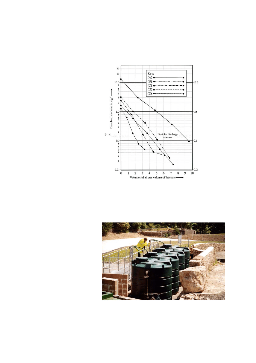
Guidance for the Treatment of Landfill Leachate
Page 40 of 182
Sector Guidance Note IPPC S5.03 – February 2007
Alternative process designs using packed towers or trickling filters with forced
aeration have often suffered from organic and inorganic fouling, and because of
the simplicity and efficiency of alternative aerated reactors, are not
recommended.
Figure 2.1:
Reduction in concentrations of dissolved methane in five
samples of landfill leachate, in a four reactor continuous flow
air stripping system, as a function of air volume used (after
Robinson et. al., 1999) (bullet points represent treatment
achieved within a specific reactor)
Plate 2.1:
Typical methane stripping plant, treating up to 300 m
3
/d of
landfill leachate, at Kendal Fell Landfill, Cumbria, 2002

Guidance for the Treatment of Landfill Leachate
Page 41 of 182
Sector Guidance Note IPPC S5.03 – February 2007
Environmental issues and concerns
Provided that adequate volumes of air are used during the stripping process,
concentrations of methane present in exhaust gases will be well below
explosive levels. Of greater concern, especially in leachates from relatively-
recently emplaced wastes, may be potential for release of odorous gases during
the stripping process. The significance of such releases can rapidly be
assessed by use of pilot-scale stripping trials, involving collection of gas
samples for formal testing using odour panels (where members of the public
determine at what dilution such odours are detectable, in controlled trials).
Although at the great majority of full-scale methane stripping installations in the
UK, such odour effects have been minimal and have not required specific
treatment, at some sites gas biofilters (e.g. brushwood or heather filters) have
been successfully installed.
Additional impacts/concerns at leachate methane stripping plants relate closely
to the composition of specific leachates. Foaming may sometimes be an issue,
particularly in treatment of leachates from more recent wastes, and can require
routine addition of small quantities of antifoam agents.
A further potentially serious issue to be addressed is the precipitation of
inorganic scale within the stripping reactors, or downstream pipework, as the
stripping process also removes dissolved carbon dioxide, and oxidises metals
such as iron. This has been addressed successfully using a variety of systems,
including electromagnetic inhibitors, acid addition/pH control, and simple routine
de-scaling programmes.
Because reactors used are relatively vulnerable, and contain untreated raw
leachate, good practice should generally incorporate secondary containment by
bunding in sensitive locations. Simple telemetry and alarm systems are widely
available and used.
Continuous monitoring of levels of dissolved methane in final effluents using
membrane probes has proved unreliable at present. Alternative, indirect
measurements, (such as PPM methane values in off-gases from the final
stripping reactor) could be incorporated as could continual monitoring of
dissolved oxygen, but simpler systems such as fail-safe shutdown and alarm
systems when blowers fail to operate/ draw current are likely to be more reliable
at present.
2.1.3.1.2 Ammoniacal-N removal by air stripping
General information
Ammonia can be removed from leachates as a gas, using air stripping, as an
alternative to biological nitrification. Ammonia dissolves in water to form the
ammonium ion in the following manner:
NH
3
+
H
2
O
=
NH
4
+
+
OH
-
Ammonia gas
ammonium
The relative proportions of dissolved ammonia gas, and of ammonium ions,
depend on the pH-value and the temperature of the water. Only the ammonia
form is removed (as ammonia gas) by air stripping, and at normal temperatures
and neutral pH-values in leachates or other waters, only a small proportion (<2
percent) of the total ammoniacal-N will be in the gaseous ammonia form.
At raised pH-values or temperatures, concentrations of dissolved ammonia gas
adjust to an equilibrium between liquid and gaseous phases, and ammonia can
be stripped from the liquid within the gas stream (usually air). The efficiency of

Guidance for the Treatment of Landfill Leachate
Page 42 of 182
Sector Guidance Note IPPC S5.03 – February 2007
the process is increased significantly by increasing values of pH or temperature,
and with increasing efficiency the quantity of air required will decrease, and the
concentration of ammonia gas in the exhaust air increases. Typically, either pH-
values in excess of 10.0, or temperatures in the order of 60-70°C, are needed to
achieve greater than 80 percent of ammoniacal-N in the gaseous ammonia
phase, to provide an efficient removal process.
Unlike many other treatment processes, the required air volume removes a
constant percentage of the incoming ammonia, regardless of influent
concentrations in leachate, the progressive removal of ammoniacal-N therefore
operating in a “half-life” manner. This has two consequences – first, at very
high concentrations of ammoniacal-N, the stripping process is increasingly cost-
effective; and second, it becomes difficult or costly to achieve low effluent
concentrations of ammoniacal-N, such as below 50 or 100 mg/l. On this basis,
ammonia stripping will generally only prove to be cost-effective, where partial
pre-treatment is required, for example, prior to discharge into the public sewer,
or before further removal of ammoniacal-N in a subsequent stage of biological
treatment.
In achieving relatively low effluent values of ammoniacal-N (e.g. <50 mg/l), very
large volumes of air will be required and this generally makes air stripping
uncompetitive in cost terms for such applications.
Process overview
Ammonia stripping can be carried out in tanks or lagoons, packed towers, or in
counter-current, multi-stage reactors. A consequence of optimisation of the
process, to achieve reduced aeration requirements, is that air containing high
concentrations of ammonia gas (to tens of grammes per cubic metre, equivalent
to 10 percent by volume), can be released. This is likely to cause unacceptable
health hazards at most sites, and must therefore be controlled. One option
would be absorption of the ammonia in sulphuric acid, to produce ammonium
sulphate, which may have potential for use as an agricultural fertiliser. Another
possible solution is thermal destruction of the ammonia to nitrogen gas, ideally
within a high efficiency landfill gas flare.
Few full-scale ammonia stripping systems have been installed for treatment of
leachates at UK landfill sites. A few based on alkali dosing have failed, or
rapidly been abandoned, as a result of environmental impact, operational
difficulties or excessive cost of reagents. At least one plant in the UK plant uses
leachate heating to enhance the stripping of ammonia. In recent years this
technology has become established as a pre-treatment step for leachates in
Hong Kong, from some of the largest landfill sites in the World (e.g. see Eden,
2001).
At three initial sites where such systems were installed in Hong Kong, leachate
flows were typically in the range 720-1800 m
3
/d, and concentrations of
ammoniacal-N of 6700 mg/l in leachate were used for design purposes. The
plants could efficiently remove these high concentrations of ammoniacal-N
down to below 100 mg/l, before subsequent biological treatment of effluent in
sequencing batch reactor (SBR) plants. Landfill gas was used to raise leachate
temperatures to 70°C before passage to the stripping tower, and effective
thermal destruction of ammonia gas (>99.99 percent) has been achieved within
the landfill gas flare.
Environmental issues and concerns
Although ammonia stripping can be an effective and cost-effective treatment
process for large volumes of very strong landfill leachate, application for use on
a smaller scale at UK landfills is limited.

Guidance for the Treatment of Landfill Leachate
Page 43 of 182
Sector Guidance Note IPPC S5.03 – February 2007
The control and destruction of ammonia gas is of primary concern. When
considering the utilisation of landfill gas flares for thermal destruction the
consideration must be given to the impact on the emissions from the flare.
2.1.3.1.3 Stripping of other volatile contaminants
Significant removal of a number of trace organic components, often present in
landfill leachates, can be achieved during air stripping treatment processes.
Recent work carried out for the Environment Agency has provided guidance to
landfill operators making reports of emissions under the Pollution Inventory (see
Robinson and Knox; 2001; 2003) and has provided the following examples of
such compounds:
Table 2.1
Trace organic components found in leachate
Compound
LOD (µg/l)
Presence
(%)
median value
(µg/l)
% removal
Ethylbenzene
10
15
10
40
Mecoprop
(MCPP)
0.1
98
11
50
Naphthalene
0.1
70
0.46
40
Toluene
10
54
21
25
Xylenes
10
35
35
40
(Notes: LOD = limit of detection achievable routinely in leachate samples;
presence (%) represents percent of samples in which compound was above the
limit of detection).
For several other substances, some present in only a small proportion of
leachate samples, air stripping may also provide significant removal, but in the
study above, no data were obtained.
It is unlikely that an air stripping treatment system would be employed
specifically to reduce concentrations of such trace components in landfill
leachates. To achieve this would be expensive, and require specific detailed
process design information. Nevertheless, such compounds may well be
present in exhaust air from other stripping processes, albeit at extremely low
concentrations.
2.1.3.2 Reverse osmosis
General information
The reverse osmosis (RO) technique aims to extract clean water from the
aqueous solution of organic and inorganic contaminants that constitute the
landfill leachate.
The process exploits the natural phenomenon of osmosis where by, if two
aqueous solutions, with different degree of concentration, are separated by a
semi-permeable membrane, water from the weakest solution will pass through
the membrane to dilute the higher concentration solution on the other side. The
process will continue till solutions on both side of the membrane display the
same degree of concentration.
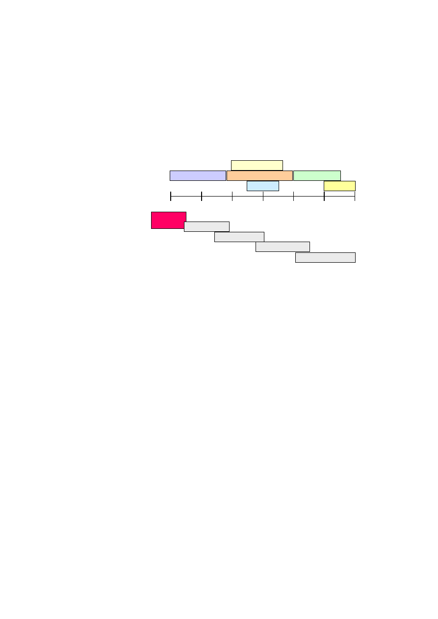
Guidance for the Treatment of Landfill Leachate
Page 44 of 182
Sector Guidance Note IPPC S5.03 – February 2007
With reverse osmosis the process is reversed. Pressure is applied to a water
solution, (leachate), against a semipermeable membrane forcing the water
molecules to pass through the membrane, thus forming the clean “permeate”.
The majority of the solutes or contaminants will be left behind forming the
“concentrate”.
Reverse osmosis is the finest physical separation method known. In contrast to
normal filtration where solids are eliminated from a liquid, reverse osmosis
succeeds in removing solutes from a solvent.
As a technology, RO is well established in wastewater treatment applications.
pollen
bacteria
viruses
org. macromolecules
colloides
dissolved salts
gravel-filtration
micro-filtration
0.2-5 bar
ultra-filtration
1-10 bar
reverse
osmosis
10-120 bar
nano-filtration
5-10 bar
0.0001 µm 0.001 µm
0.1 µm
0.01 µm
10 µm
1 µm
100 µm
(0.1 mm)
pollen
bacteria
viruses
org. macromolecules
colloides
dissolved salts
gravel-filtration
micro-filtration
0.2-5 bar
ultra-filtration
1-10 bar
reverse
osmosis
10-120 bar
nano-filtration
5-10 bar
0.0001 µm 0.001 µm
0.1 µm
0.01 µm
10 µm
1 µm
100 µm
(0.1 mm)
0.0001 µm 0.001 µm
0.1 µm
0.01 µm
10 µm
1 µm
100 µm
(0.1 mm)
Figure 2.2:
Filtration range comparison
Advances in membrane technology, in particular in the last 15 years, have
allowed the development of RO systems designed specifically for the treatment
of leachate.
The retention efficiency is primarily depended upon the molecular weight and
polarity of contaminants.
Reverse osmosis membranes can result in the retention of more than 98% of
large molecules dissolved in leachate. Ions of valance 1 such as Na
+
, Cl
-
can
also be retained.
Most commercially available plants are constructed as two stage plants with
contaminant removal rates better than 99.6%. Where unusually high strength
leachate is treated or very stringent discharge consents apply, three stage
plants can be employed and achieve contaminant removal rates better than
99.98%.
Reverse osmosis leachate treatment plants are widely used on landfill sites
throughout Europe including Germany, France, Holland, Belgium, Italy,
Switzerland, Spain, Portugal and Greece. More than 100 plants are currently
operational some of them for longer than ten years.

Guidance for the Treatment of Landfill Leachate
Page 45 of 182
Sector Guidance Note IPPC S5.03 – February 2007
Table 2.2:
Retention effect [%] against number of stages (see
Packheuser 2002)
Average retention effect (%)
Number of stages
Parameter
1
2
3
COD
91.5
99.89
99.999
BOD
5
88.5
99.78
99.996
TOC
91.5
99.90
99.999
AOX
87.5
99.81
99.998
NH
4
-N
85.0
99.65
99.987
PO
4
-P
96.5
99.90
99.998
Modern 2-stages RO plants do reliably and consistently separate 75% - 83% of
leachate volume into a high quality water stream. Plants specially configured
can increase yield to 90%, (yield refers to production of “permeate” as a
percentage of the treated leachate volume).
The main advantage of the RO process, in treating leachate, is the high quality
of permeate produced. More than 99.9% of the contaminants can be retained
and their release to the environment avoided.
As a non-biological process, RO is quite insensitive to changes in leachate
strength. Though changes in leachate composition will effect the quality of
permeate, well designed plants will sense this and adjust automatically either
the throughput or/and yield ratio to compensate.
RO plants can operate intermittently; indeed RO plants do require frequent
stoppages to “wash” the membranes. Washing of the membranes is done with a
solution of membrane detergent and permeate produced by the plant. There is
no requirement for a fresh water supply permanently connected to the plant
though a supply should be made available close to the plant for use during
maintenance and in cases were the permeate store is exhausted. “Wash” cycles
are generally managed automatically and their frequency is governed by the
level of contaminants in the leachate and in particular those of Calcium, BOD
5
,
COD etc.
Most plants able to reach steady state and full production within 10 to 15
minutes from re-starting. However switching the plant off frequently increases
detergent usage, as most plant will go though a membrane wash cycle before
shutting down.
The ability of RO plants to operate intermittently as well as their ability to adjust
to leachate composition changes minimises the requirement of large balancing
tanks/lagoons. However, care needs to be taken in designing such installation
to provide adequate leachate storage capacity to allow for planed and
unplanned maintenance of the equipment. Typically an RO installation will
display better that 90% plant availability. The availability of the plant should be
taken into account in designing the storage requirement as well as selecting the
maximum capacity of the plant.
Commercial plants are generally containerised modular plants that are fully
automated and capable of been monitored and controlled remotely. Standard
modules are available with leachate throughput capacities from 30 m³/day up to
200 m³/day housed in single 40” ISO containers.
This modular approach requires very little infrastructure to be in place
other than a suitably engineered hard-standing area for the plant and
chemical storage tank. Installation and commissioning of such a plant will
normally take 3 - 4 days. This allows the addition and removal of plant
from site.

Guidance for the Treatment of Landfill Leachate
Page 46 of 182
Sector Guidance Note IPPC S5.03 – February 2007
Process overview
Most commercial RO plants, designed for the treatment of leachate, are of
multi-permeate stage configuration, (typically two and rarely three stage). The
first stage provides the majority of the leachate cleaning while subsequent
stages “polish” the permeate further.
The plants use artificial, semi-permeable membranes of thin film composite
construction. Such membranes have high salt rejection and display very high
physical and chemical durability. Membrane manufacturers and in particular
those of spiral wound type have optimised the construction of these membranes
for use with leachate.
The membrane modules are mounted inside pressure tubes on racks, complete
with interconnecting pipework and re-circulation pumps which circulates
leachate in each membrane block in order to provide constant conditions on the
membrane surface. The feed to a membrane must be of a sufficiently high
velocity in order to provide an effectual overflow of the membrane surface to
avoid concentration polarisation and fouling effects that would decrease their
efficiency.
RO plants are designed to provide as large a surface area of membrane as
possible for a given treatment unit, based on calculated flux rates of permeate
through the membranes. Peters (1999) has stated that flux rates achieved
depend on many parameters, and has reported typical values of between 13
and 15 litres of permeate per square metre of membrane per hour.
Flux rates gradually reduce during periods between cleaning of membranes,
and over the life of membrane components, which is typically 1.5 to 2 years.
A variety of membrane module systems are available including; proprietary
tubular modules, spiral wound modules, hollow fibre modules and disc tube
modules. Standard spiral wound modules, hollow fibre modules and disc tube
modules are sensitive to the presence of solids in the leachate. For this reason
RO plants incorporate a pre-filtration stage by sand-filters and fine filters.
Continuously working reverse osmosis plants operate fully automatic. Operation
parameters are permanently recorded and displayed. Start and shutdown
procedures occur automatically. In most cases remote control is possible
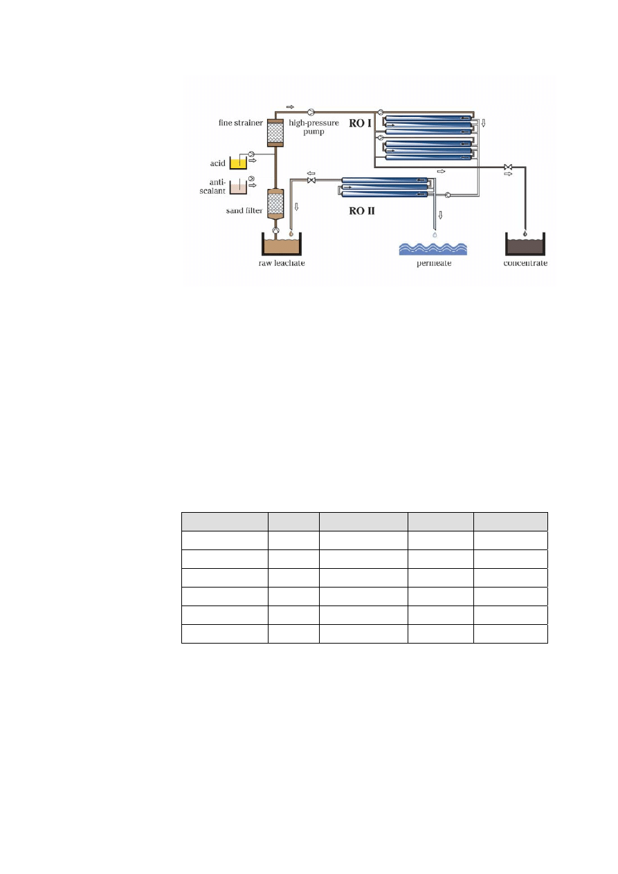
Guidance for the Treatment of Landfill Leachate
Page 47 of 182
Sector Guidance Note IPPC S5.03 – February 2007
Figure 2.3:
Typical process scheme of a 2-stage RO plant
The quantitative cleaning efficiency of reverse osmosis plant can vary between
50% and 90% clean permeate effluent. Experiences on European landfills
treating “strong” leachate (e.g. ammoniacal-N >1000 mg/l) show, that values of
75% permeate yield are typical.
Permeate is normally suitably clean to be allowed direct discharge without any
further treatment. The concentrate is in normally re-infiltrated in the landfill body.
In some cases, the RO concentrate has to be treated or disposed off site. In
such cases an additional high pressure 2-stages concentrate stage (High
Pressure RO, HPRO) can be included, after the standard plant, to further
reduce the volume of concentrate. The total quantitative efficiency can be
increased to nearly 90% permeate.
Table 2.3:
Typical performance data from a 2-stages RO with 2-stages
HPRO for concentrate treatment. (see Kolboom 2005).
Parameter
unit
Raw leachate
Permeate
Concentrate
Yield
mg/l
100
89
11
COD
mg/l
835
15.0
7300
Ammoniacal-N
mg/l
406
6.11
2480
Nitrate-N
mg/l
0.2
<0.1
-
Conductivity
mS/cm
11.25
0.2
51.1
pH
-
7.45
6.8
7.36
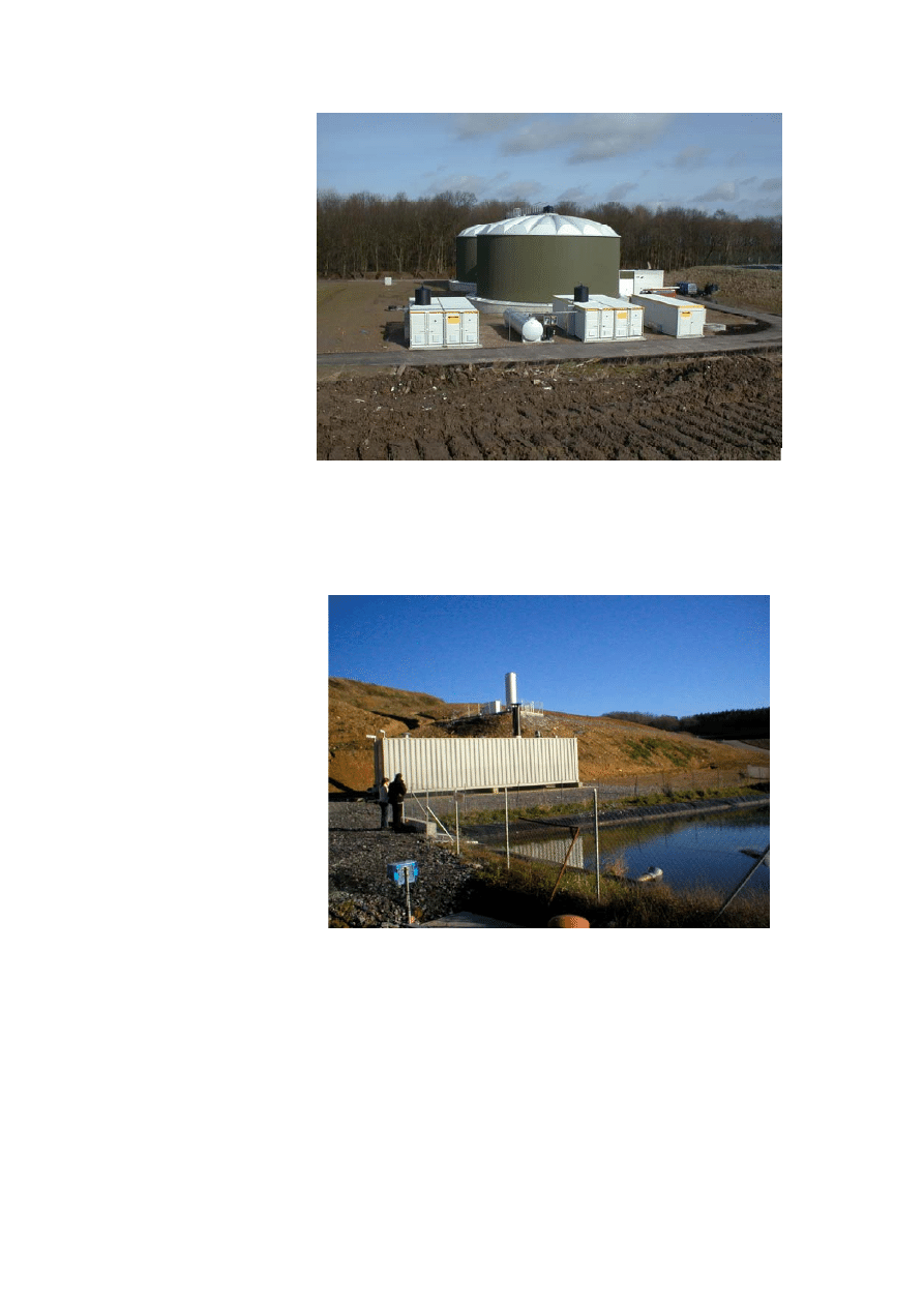
Guidance for the Treatment of Landfill Leachate
Page 48 of 182
Sector Guidance Note IPPC S5.03 – February 2007
Plate 2.2:
Typical configuration of two 2-stage RO plant with leachate
tanks, direct permeate discharge and concentrate re-
infiltration (350 m³/d, Niemark landfill, Luebeck Germany,
commissioned 1999).
Plate 2.3:
Typical configuration of a 2-stage RO plant with leachate
lagoon, direct permeate discharge and concentrate re-
infiltration (72 m³/d, landfill CSDU Pays des Graves, district
Hautes-Pyrenees, Commune de Lourdes, France,
commissioned 2004) (see Wachter 2005)
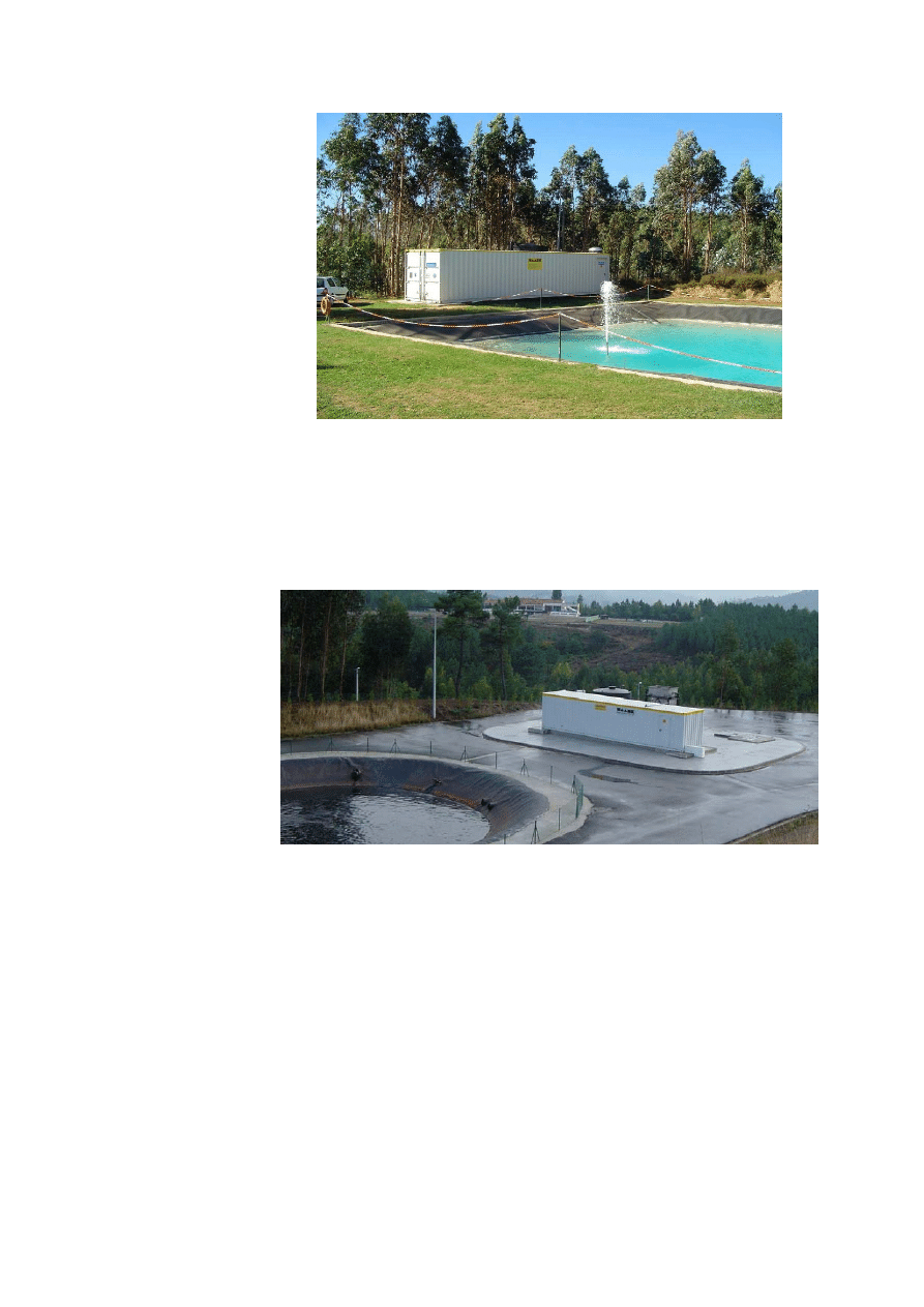
Guidance for the Treatment of Landfill Leachate
Page 49 of 182
Sector Guidance Note IPPC S5.03 – February 2007
Plate 2.4:
Typical configuration of a 2-stage RO plant with permeate
lagoon (140 m³/d, Tondela landfill, district of Tondela,
Portugal, commissioned 2004) (see Loeblich 2005)
During the late 1990s a lot of RO leachate treatment systems where designed
with an aerated lagoon in front of a 2-stages RO plant. The advantage of this
configuration is that an aerated lagoon reduces the NH
4
-N, BOD
5
and COD
level by its biologic activity.
Plate 2.5:
Typical configuration of a 2-stage RO plant with aerated
leachate lagoon, direct permeate discharge and
concentrate re-infiltration (120 m³/d, Rebat landfill, district
of Amarante, Portugal, commissioned 2001) (see Loeblich
2005)
Guidance for the Treatment of Landfill Leachate
Page 50 of 182
Sector Guidance Note IPPC S5.03 – February 2007
Table 2.4:
Performance data from 2-stages RO plants
Environmental issues and concerns
The production of a high quality effluent (permeate) is a significant advantage of
the RO process. In particular the removal of non-degradable components of
leachate such as chloride, or residual COD and heavy metals. However, all
these contaminants are present within the concentrate, which can be 10%-25%
of the leachate volume. In the majority of cases concentrate is returned to the
landfill, in other instances the concentrate is disposed of off site. In addition, all
chemicals required for effective operation of an RO plant are contained in the
concentrate. This amounts to about 0.3% of each cubic metre of leachate
treated. Chemicals including citric acid, membrane cleaner and anti-scaling
detergents. Modern designed membrane modules do not require treatment with
biocides.
Disposal of concentrate is a key factor to be addressed. To date, concentrates
have widely been recirculated back into landfilled wastes. The sustainability of
this practice would have to be assessed on a site by site basis. Some data
indicates that the return of concentrate to the landfill coincides with an increase
in concentration in the leachate of COD and NH
4
-N as well as an increase in
conductivity. However, other data (Loeblich 2005 and Blumenthal 2005) shows
that on some European sites there is no significant increase in diluted
contaminants in landfill leachate following the commencement of concentrate
return.
Neimark Landfill,
Luebeck, Germany
(Kolboom 2005)
ZMD-Rastorf Landfill,
Rastorf, Germany
(Becker 2003)
Parameter
Leachate
Permeate
Leachate
Permeate
COD (mg/l)
1024
15
2500
22
BOD
5
(mg/l)
40
0.6
-
-
Ammoniacal-N (mg/l)
388
6.1
2100
4
Nitrate-N (mg/l)
3.44
0.1
-
-
Conductivity (
µS/cm)
8310
48
1810
78
pH
7.44
6.5
6.4
4.33
Suldoro Landfill,
Portugal,
(Loeblich 2002)
Lamego Landfill
Lamego, Portugal
(Loeblich 2002)
Parameter
Leachate
Permeate
Leachate
Permeate
COD (mg/l)
17780
28
17029
23
BOD
5
(mg/l)
10000
8
11350
15
Ammoniacal-N (mg/l)
3140
9
891
1.01
Nitrate-N (mg/l)
101
0.8
-
-
Conductivity (
µS/cm)
20000
80
15400
18
pH
8.9
5.4
6.9
5.7

Guidance for the Treatment of Landfill Leachate
Page 51 of 182
Sector Guidance Note IPPC S5.03 – February 2007
When considering the sustainability of the return of concentrate to the landfill:
-
any predicted change in leachate concentration should be assessed;
-
it must be shown that the landfill is adequately engineered so that the
concentrate does not cause pollution (particular attention should be given to
the impact on groundwater);
-
it must be shown that the leachate treatment system can adequately treat
any predicted change in leachate quality resulting from the return of the
concentrate; and
-
chemicals essential to the effective operation of the plant should be
selected so as not to compromise the disposal of the concentrate.
Secondary concentrate treatment processes, such as evaporation and dryers,
have been used to reduce volumes further in countries such as Germany, the
Netherlands, Belgium, France, Portugal, Spain (where RO plants are most
widely used for leachate treatment), the residues from these processes have
been stored in barrels within old mines. Since most of the solid material is
readily soluble, highly engineered containment is required indefinitely. Most of
the leachate dryers are out of operation now.
Reverse osmosis systems have also been used to treat leachates from landfills
that have received residues from MSW incinerators. Hanashima et. al. (1999)
reported RO tests using disc tube modules at one such site. Although
leachates contained concentrations of chloride above 6000 mg/l, 95 percent
permeate recovery was reported, and concentrations of dioxins were also
reduced by up to 99.8 percent.

Guidance for the Treatment of Landfill Leachate
Page 52 of 182
Sector Guidance Note IPPC S5.03 – February 2007
2.1.3.3 Solids removal
It may be necessary to remove solids from either raw leachates or from pre–
treated leachates prior to disposal. Processes most commonly used include
sedimentation/settlement, sand filtration, dissolved air flotation or membrane
filtration.
2.1.3.3.1 Sedimentation and settlement
Provision of sedimentation or solids settlement stages for pre-treatment for raw
leachates is rarely appropriate, and there are very few situations in the UK
where such facilities have been used.
Use of coagulation and flocculation processes, not only to reduce levels of
suspended solids in leachates, but to provide additional removal of colloidal and
other contaminants, is discussed separately below.
An efficient sedimentation/settlement stage of treatment is essential to achieve
adequate clarification of effluents following biological treatment of leachates,
and these issues are considered separately within that section.
2.1.3.3.2 Sand filtration
General information
Sand filtration involves the passage of the effluent through a high quality sand
media with a specific particle size range between 0.8-1.7mm. The application of
sand filtration processes of any sort to raw leachates will rarely be appropriate.
Operational difficulties such as generation of biological sludges, or of
uncontrolled partial biological processes, might potentially cause great
difficulties.
Nevertheless, the use of tertiary sand filtration processes can make a significant
improvement to the quality of effluents from biological stages of treatment, not
only in terms of concentrations of suspended solids, but also of other associated
contaminants (e.g. BOD
5
, COD, iron).
Although continuous backwash sand filters are in use world wide, they have to
date only occasionally been applied to treatment of leachate. There have been
a few applications in the UK, where they have been specified for polishing of
biologically pre-treated leachates, and in appropriate circumstances they have
great potential for this purpose
Units have the advantage that they are generally transportable, and can readily
be trialled or used on a temporary basis. They are relatively simple in
operation, and lend themselves well to automation and telemetry/failsafe
programming. On the other hand, they can be relatively expensive per kg of
solids removed basis, and their height (typically 8m or more) may sometimes
cause planning difficulties.
Process overview
Fixed bed sand filters, where a media (usually graded sand) traps and removes
suspended solids from water passing through the media, may operate using
gravity to drive water downwards, or by means of pressure applied from a
pump. For both types of filter, the bed builds up head loss over time, as solids
accumulate within it. When this pressure head loss becomes unacceptable, as
solids are progressively entrained within the sand media, the filter needs to be

Guidance for the Treatment of Landfill Leachate
Page 53 of 182
Sector Guidance Note IPPC S5.03 – February 2007
backwashed, by reversing the flow of water to an upward direction. Backwash
water (generally, treated effluent is used), sometimes using air to agitate the
sand media, with addition of chemicals and released particles are usually
discharged into a balancing tank, or may be returned into the original biological
treatment process. Backwashing is automatically controlled either by adjustable
timers, or by sensors which detect when the pressure differential exceeds a pre-
set value. During the period of backwashing, no effluent can be treated by the
bed.
The volume of backwash water produced will be determined by the
concentrations of suspended solids in the feed, to some extent by their nature,
and by the concentration of suspended solids required in the effluent. Many
proprietary systems for fixed bed filtration are available, but few have been used
in the UK for either raw leachate pre-treatment, or for final polishing of
biologically treated effluents.
The resultant final effluent from a sand filtration system can have low levels of
residual solids, and the application is particularly useful for discharge to river.
The interception of solids can also be a useful technique for the removal of
substances capable of bioaccumulation, which may be present in biological
solids, or in some colloids.
Recently, tertiary treatment of biologically treated leachate has been carried out
using a recovered media made from waste glass, with a particle size range of
0.5-1.0mm. The much smoother surface of the recovered glass has enabled
the media to be cleaned more effectively using simple backflushing, and the
removed solids have been returned to the treatment process. This has been
particularly useful for maintaining nitrifying bacteria in the treatment process,
and for the elimination of list 1 substances from the discharge.
An alternative type of sand filter is the moving bed, or continuous backwash
filter, which has been developed into several forms, the most well-known being
the proprietary “DynaSand®” system, which is currently in use in tens of
thousands of applications Worldwide, since its introduction 2 or 3 decades ago.
The moving bed sand filter operates continuously, avoiding the need for periodic
shutdowns to allow the sand to be backwashed, as sand is cleaned
continuously by means of an internal washing system. The process is based on
the countercurrent principle (see Figure 2.4), with dirty water entering the unit at
the bottom, and travelling upwards, through the downward-moving fluidised
sand bed. Suspended solids are strained from the rising water, by filtration and
adsorption.
An airlift pump and draft tube, in the centre of the unit, recirculate sand and
filtered particles from the bottom of the filter to the top of the vessel, which is
usually open, into a separation box at the top of the unit. Here sand is
separated from the removed suspended particles by turbulent action, the
heavier grains of cleaned sand falling back into the top of the filter, and the
lighter solid particles flowing over a weir to waste. As a result, the sand bed is
in slow, constant downward motion through the unit, water purification and sand
washing take place continuously, and no moving parts are involved in the
system. Chemical flocculants (e.g. FeCl
3
) can sometimes be added to water
being treated, to improve the performance of the process.
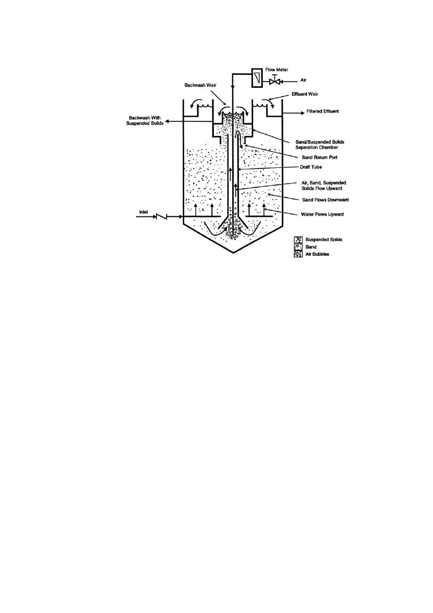
Guidance for the Treatment of Landfill Leachate
Page 54 of 182
Sector Guidance Note IPPC S5.03 – February 2007
Figure 2.4
The moving bed sand filter process
2.1.3.3.3 Dissolved air flotation (DAF)
General information
Although few full-scale DAF units have yet been applied to treatment of
leachates at UK landfills, the process has an extensive track record in many
industries, and has shown great promise in some projects for polishing of
effluents from biological treatment of leachates. An extremely successful DAF
system polishes effluent at the biggest leachate treatment plant in the UK, at
Arpley Landfill in Warrington. Another unit has been recently installed at a
leachate treatment plant constructed at Marston Vale in Bedfordshire. A number
of other systems are planned for commissioning and operation in the near
future.
Optimisation of the coagulation process prior to DAF treatment is key to
increasing the efficiency of treatment, and is readily effected by specialists using
experimental trials. The relatively short hydraulic retention time of the process
can make DAF more sensitive to non-optimum or inconsistent coagulation
control, however, biological leachate treatment processes such as SBRs, that
give rise to intermittent discharges of consistent effluent, are ideal, as this can
then be treated gradually over an extended period.
Process overview
Dissolved Air Flotation (DAF) is a process for the removal of fine suspended
material from an aqueous suspension, in which solid particles are attached to
small air bubbles, causing them to float to the surface. Attraction between the
air bubbles and the particles results from adsorption forces, or physical
entrapment of bubbles within the particle, colloid or floc. Chemical conditioning
is generally used to increase the effectiveness of the DAF process, and
optimisation of coagulation processes prior to DAF is key to improving effluent

Guidance for the Treatment of Landfill Leachate
Page 55 of 182
Sector Guidance Note IPPC S5.03 – February 2007
quality and minimising unit costs.
The most commonly adopted method of producing micro-bubbles of the
optimum size (20-70 µm) is by recycling a proportion of the treated water
through a pressurised (typically 2-5 bar) air saturation system, where it is
saturated with air at the high pressure. Water then passes through a pressure
relief nozzle in the base of the DAF tank within which air precipitates as tiny
bubbles, with an enormous surface area.
A key benefit of this process of producing bubbles is that it produces a very
positive attachment between air bubbles and the particles it is required to
remove. Particles, colloids or flocs act as nucleation sites for the bubbles to
precipitate on, which is a much more effective process than relying on contact
between particles and larger bubbles introduced by some other means.
The rising particles float to the surface of the water, forming a scum/sludge layer
which is removed, usually by means of mechanical scrapers or scoops. Treated
water flows out from a lower level.
The first UK application of DAF to a leachate treatment system was at Arpley
Landfill in Warrington, during 2001/2002. Effluent from biological treatment of
very strong leachate (ammoniacal-N 2,500 mg/l, COD to 10,000 mg/l,
conductivity 20,000 µS/cm) within an SBR, is treated using DAF, before
receiving final polishing in a reed bed, and being discharged into the River
Mersey to meet a strict discharge consent (see Robinson et. al. 2003). A
relatively small DAF unit (see Plate 2.6) is able to treat effluent at the required
rate of up to 20 m
3
per hour (450 m
3
/d), and incorporates initial polyelectrolyte
dosing.
Environmental issues and concerns
Providing that the process is well-specified, installed and operated, it should
give rise to few environmental impacts or concerns. The DAF process uses
limited energy, and few chemicals, sludge production representing less than
about 1 percent of volumetric throughout, which can readily be disposed of
either back to landfill, or via occasional road tanker to a sewage treatment
works.
The Arpley unit has demonstrated not only the effective reduction in
concentrations of suspended solids, typically from 250 mg/l to <40 mg/l, but also
the associated reductions in levels of organic materials in non-degradable COD,
many of these being present within colloidal materials which are effectively
removed by the DAF process.
Table 2.5 provides typical operating data for the DAF unit.
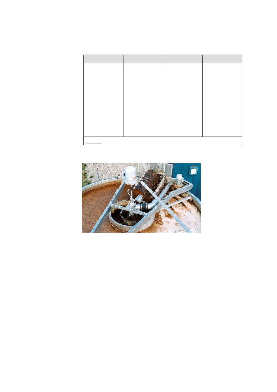
Guidance for the Treatment of Landfill Leachate
Page 56 of 182
Sector Guidance Note IPPC S5.03 – February 2007
Table 2.5 Treatment of SBR effluent in a DAF unit at Arpley
Landfill Site, Warrington, UK (after Robinson et. al.,
2003)
Determinand
Leachate
SBR effluent
DAF effluent
COD
5990
1470
1060
BOD
20
1720
67
6
BOD
5
688
20
<1
TOC
1240
356
281
Ammoniacal-N
1460
3.7
3.2
Nitrate-N
1.9
1490
1238
Iron
13.0
5.51
0.72
Sodium
2560
3490*
3770*
Chloride
2710
2300
2650
Notes: results in mg/l, * = related to dosing of NaOH as alkalinity
Plate 2.6:
The main DAF treatment tank at Arpley Landfill
2.1.3.4 Activated carbon adsorption
General Information
Adsorption is the transfer of (generally) organic compounds from a liquid phase
onto the surface of a solid material, and its extent is related to chemical and
physical properties of each. Several adsorbent materials may be used, but for
removal of organic compounds from leachates, to date only activated carbon
has been found to be cost-effective.
Activated carbon is a highly porous and crude form of graphite, with a wide
range of pore sizes, and very large surface area of hundreds of m
2
per gramme.
It can be made from coal, wood, peat, coke or coconuts, and adsorption
capacities of greater than 10 percent by weight are possible. In the field of
drinking water or groundwater treatment, activated carbon is widely used to
remove trace levels of organic substances that can impart flavours to water.
The performance of activated carbon for removal of organic compounds is

Guidance for the Treatment of Landfill Leachate
Page 57 of 182
Sector Guidance Note IPPC S5.03 – February 2007
influenced by the:
• capacity of a specific carbon to adsorb a specific organic compound;
• concentration of the organic compound in the feed;
• contact time between water and carbon;
• loading rate applied to the carbon; and
• presence of other organic compounds which may compete for adsorption
sites.
Activated carbon is normally used in either a powdered form (PAC), or in a
granular form (GAC). When the adsorption capacity of the carbon becomes
exhausted, it may be possible to regenerate GAC using specialised equipment
(at 2 or 3 locations in the UK). The accumulated organic compounds (often
concentrated to hazardous levels) are removed from the carbon and thermally
destructed, with less than 10 percent mass loss of the GAC, (resulting from
general attrition processes). In contrast, PAC is normally used only once, and
then disposed of rather than regenerated.
Activated carbon is capable of removing significant quantities of BOD and COD,
however due to the relatively high costs of activated carbons, in many cases it is
more economical to utilise the synergies between biological treatment and
activated carbon. In leachate treatment it is generally restricted to polishing of
effluents that have previous been treated using biological, or rarely other,
processes. Occasionally activated carbon has been used in biological treatment
plants to provide a buffering effect and reduce toxic shock when highly
contaminated leachate enters the system.
The effectiveness of a carbon adsorption process is described by a function
known as an adsorption isotherm. The adsorption capacity of carbon is the
mass of adsorbed contaminant per mass of activated carbon (e.g. mg COD/g
AC). This value is measured at several effluent values of COD (in mg/l) to
provide the isotherm curve, which can be determined by simple and small-scale
laboratory experiments. Because of variability between specific AC materials,
and in the many compounds which comprise residual COD values, generic data
are unhelpful, and site-specific tests using several different AC sources are an
essential part of a design process.
2.1.3.4.1 Powdered activated carbon (PAC)
Process overview
PAC may in certain circumstances be cheaper than GAC, but cannot be
reactivated, and so must be disposed of after a single use. PAC is dosed as a
slurry, to achieve a desired concentration of PAC in mg/l, and a contact period
in the order of 30 minutes to an hour, within an aerated or fully-mixed reactor
(see Plate 2.7 below).
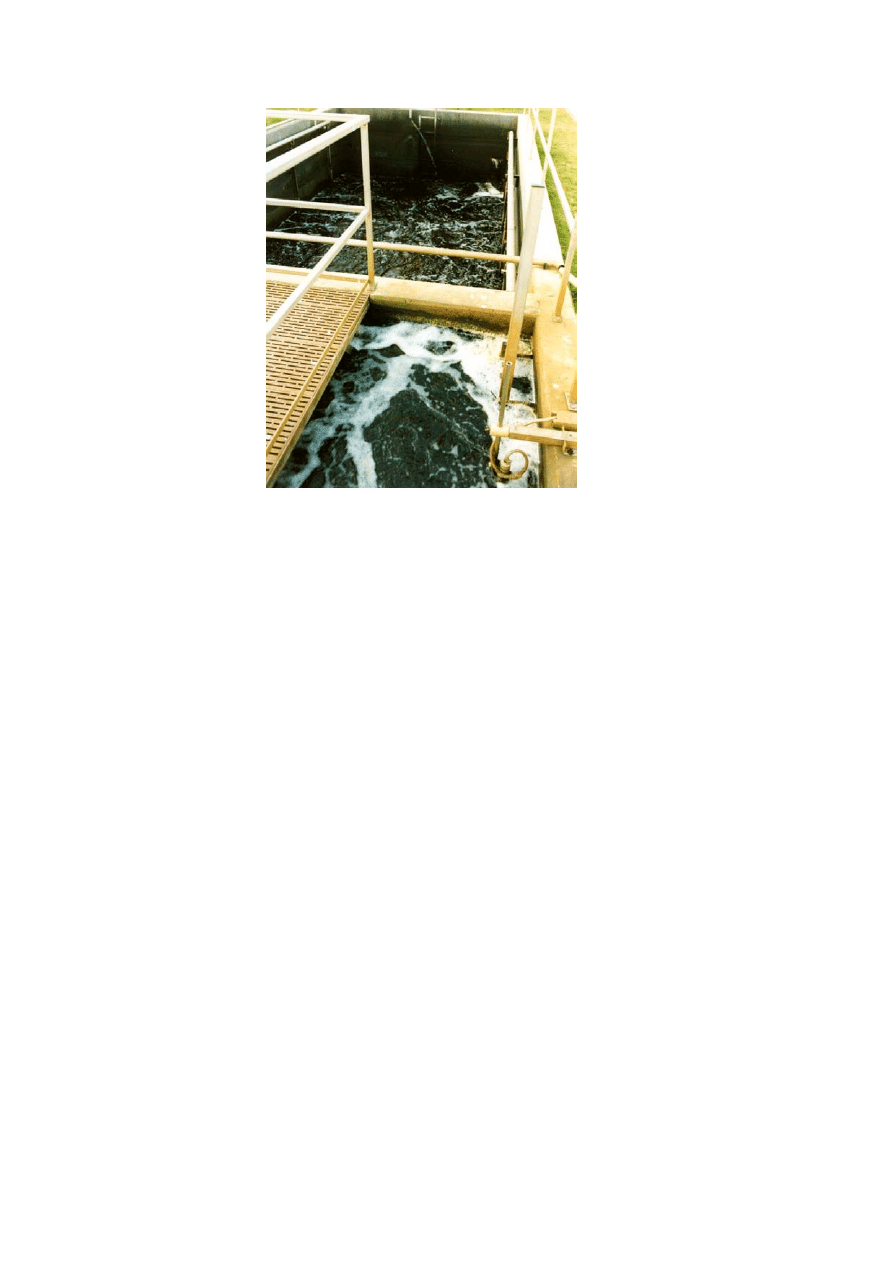
Guidance for the Treatment of Landfill Leachate
Page 58 of 182
Sector Guidance Note IPPC S5.03 – February 2007
Plate 2.7:
Typical reactor (35 m
3
) for contact with PAC in
treatment of landfill leachate
The mixed liquor must then be treated to remove the PAC, by subsequent
processes, such as coagulation, flocculation, or filtration.
During the 1980s and early-mid 1990s, PAC was widely used in Germany as a
final polishing step after biological treatment of leachates, primarily as a means
of achieving nationally-applied standards for COD and AOX (adsorbable organic
halogens) in all discharges, and waste PAC was landfilled locally. However,
later legislation limiting the disposal of waste products from water treatment
processes, meant that GAC systems are now generally preferred.
Data from the PAC systems (e.g. Albers and Kruckeberg, 1988) did
demonstrate the ability of the process to achieve significant removal of residual
COD in biologically pre-treated leachates. Typically, when treating effluent
COD values in the range 200-800 mg/l, adsorption rates in the order of 250-450
mg COD per g of PAC were maintained, and final effluent COD values of <100
mg/l could be consistently achieved.
Table 2.6 below presents data obtained from sampling of a PAC polishing
system at Minden Heisterholz, near Hannover, as part of a UK Government
research project during 1990.

Guidance for the Treatment of Landfill Leachate
Page 59 of 182
Sector Guidance Note IPPC S5.03 – February 2007
Table 2.6:
Minden Heisterholz leachate treatment plant, with PAC
1990
Determinand
Leachate
Biological effluent
PAC effluent*
COD
2320
376
75
BOD
20
627
15.0
<0.5
BOD
5
370
<0.5
<0.5
TOC
1940
171
33
Ammoniacal-N
712
0.2
<0.2
Chloride
1440
1120
1020
Notes: all results in mg/l; PAC removal by FeClSO
4
coagulation, with
polymer addition and settlement/clarification
Although operationally the process is relatively simple (for example, levels of
suspended solids in final biological effluent do not affect process efficiency)
generally at larger leachate treatment plants the reduced operational costs of a
GAC plant more than offset the extra capital costs of equipment required, and
GAC systems are preferred. The costs of disposal of spent PAC to landfill, and
environmental considerations regarding this, reinforce this decision in most
circumstances.
The main operational consideration in the use of PAC is the appropriate dose
required to achieve a desired level of treatment. This can be determined readily
on a site-specific basis by a simple batch equilibrium isotherm tests in a
laboratory. Performance may vary considerably between different carbon
materials, and different leachates. Table 2.7 below compares data from the
Minden site with results for polishing of biologically treated leachates at a range
of UK and other landfills.

Guidance for the Treatment of Landfill Leachate
Page 60 of 182
Sector Guidance Note IPPC S5.03 – February 2007
Table 2.7:
Data for removal of residual organic compounds in
biologically treated leachate effluents, using PAC
Leachate
Origin
Parameter
Influent
(mg/l)
Effluent
(mg/l)
Reduction
(%)
C. dose
(kg/m
3
)
Ref
(#)
Pitsea, UK
TOC
407
130
68
5
a
TOC
89
3.7
95
8
b
Compton
Bassett, UK
COD
249
30
88
8
b
TOC
88
6.1
93
8
b
Greengairs,
UK
COD
238
45
81
8
b
TOC
248
12
95
8
b
Summerston,
UK
COD
623
33
94
8
b
TOC
54
4
92
8
b
Harewood
Whin, UK
COD
159
16
90
8
b
MSW, USA
COD
184
18.4
90
4
c
TOC
171
33
81
~1
b
Minden,
Germany
COD
376
75
80
~1
b
References: (a) Knox (1983) (b) Robinson (1990) (c) Pohland (1975)
2.1.3.4.2 Granular activated carbon
Process overview
GAC is normally used in fixed beds or tanks, through which effluent is passed in
a controlled manner, at a controlled rate. Because such filter systems generally
use two or three identical tanks, operated in series, they provide several
benefits:
• higher effluent quality can be achieved more cost-effectively, as a result of
relatively fresh GAC always being available to contact effluent at the end of
the final tank;
• higher overall contaminant loading rates can be achieved, per kg of carbon
consumed.
As an example, a typical GAC polishing installation for COD removal might
comprise four treatment tanks. At any time, three units would be receiving
passage of effluent in series (say, numbers 1, 2 and 3), and a 4th would be
empty. Effluent quality from GAC tank 1 would be monitored for COD on a
regular basis, and as COD rose to a predetermined trigger level at this point, the
GAC could prepare to be replaced. Because the downstream tanks 2 and 3
continue to provide further treatment, with fresher carbon, maximum use could
be obtained from GAC in tank 1, until effluent COD from it approached COD
values in influent.
At this stage, a tanker would fill tank 4 with fresh GAC, then removing the spent
GAC from tank 1 to be regenerated. The new order of treatment would now be
tanks 2, 3 and 4 ensuring that, again, the freshest carbon is treating the final
effluent before discharge.
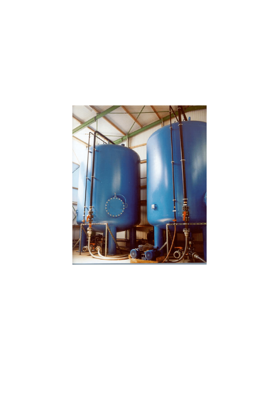
Guidance for the Treatment of Landfill Leachate
Page 61 of 182
Sector Guidance Note IPPC S5.03 – February 2007
Plates 2.8 and 2.9 below show a simple and typical GAC installation.
In general, a 3-tank system (plus one spare) provides optimum operation,
minimising overall usage of GAC. The service life of each tank of GAC depends
on the specific carbon being used, the volume of the tank, the flow rate, the
strength of the liquid being treated, and final effluent quality limits required. As
with PAC, sizing can be determined very accurately using small scale laboratory
isotherm tests. Appropriate flexible pipework layouts and valves are essential,
to allow efficient operation of the overall scheme, and reduce down-time to a
matter of minutes each time GAC is replaced (generally one tank every four
months or less).
Plate 2.8:
Typical internal sequential GAC tank installation for
polishing of biologically-pre-treated landfill leachate
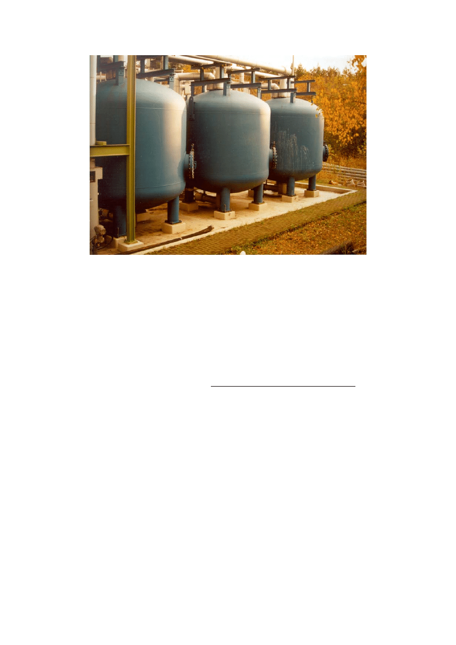
Guidance for the Treatment of Landfill Leachate
Page 62 of 182
Sector Guidance Note IPPC S5.03 – February 2007
Plate 2.9:
Typical external sequential GAC tank installation for
polishing of biologically-pre-treated landfill leachate
Hydraulic retention times in the order of 15 to 30 minutes are typical within each
tank. In order to maximise carbon usage there should be a total empty bed
contact time of between 2 to 4 hours. In some cases when discharge limits are
very tight (or flows are very small) this figure can be as high as 6 to 8 hours.
A parameter termed the “effective carbon dose” (ECD) is often used to compare
performance of different GACs, when treating different pre-treated leachates,
and is defined as:
ECD =
weight of GAC in the bed (grammes)
Volume of water treated during service run
Because concentrations of contaminants in treated water normally increase
gradually over a period of several weeks or months, sampling and analysis
frequency must be determined accordingly.
Environmental issues and concerns PAC and GAC
For either powdered or granulated activated carbon treatment systems, the
main environmental concerns relate to the disposal or regeneration of the
activated carbon itself.
During treatment, powdered activated carbon is readily and safely dosed as a
slurry, but used PAC cannot be reactivated, and so must be removed as a
sludge by processes such as coagulation, flocculation or filtration. The used
PAC is then disposed of, generally to landfill or by incineration.
GAC is delivered and used contained within reaction vessels. The spent GAC
must then be removed for regeneration, which must be undertaken at specialist
facilities.

Guidance for the Treatment of Landfill Leachate
Page 63 of 182
Sector Guidance Note IPPC S5.03 – February 2007
The presence of persistent organic pollutants that have been adsorbed onto
either form of activated carbon will limit locations where they can be
regenerated or disposed of safely.
2.1.3.5 Ion exchange
Ion exchange removes ions from an aqueous solution by the exchange of
anions or cations between contaminants and the exchange medium. Ion
exchange materials typically consist of resins made from synthetic organic
materials, which contain ionic functional groups to which exchangeable ions are
attached. They may also be inorganic or natural polymeric materials.
Ion exchange processes are most widely used in potable water treatment, and
have been successfully applied to nitrate removal, or to water softening (see
Hall and Hyde, 1992). For nitrate removal, water is passed through a bed of
synthetic resin beads, which remove anions including nitrate from the water,
exchanging them for equivalent amounts of chloride. When the capacity for
exchange is saturated, the bed is taken out of operation and the resin
regenerated with sodium chloride brine (~10 percent w/v), which returns the
resin to the chloride form. The bed is then rinsed with clean water and returned
to service. Used regenerant contains high concentrations of sodium chloride,
as well as nitrate (and sulphate) removed from the bed, and must be disposed
of, often to sewer.
For water softening, cationic resin is instead used, which can be regenerated
either using NaCl, or acid, but the process is essentially similar.
Application of ion exchange processes to the treatment or polishing of landfill
leachates has to date been limited by the very high concentrations of anions
(e.g. chloride, nitrate-N to 2000+ mg/l) and cations (e.g. sodium, calcium to
1000+ mg/l) present in raw or biologically pre-treated leachates. This continues
to restrict any cost-effective applications for leachate treatment.
The complexity and variability in composition of leachate, including the
presence of multiple contaminants makes it unlikely that naturally occurring ion
exchange materials will be suitable for treating leachate. The presence of
hydrocarbons may also cause the media to be blinded. Zeolite has been used
for ammonia removal but regeneration has not proven cost effective and
therefore the technology may be more applicable to sites where the flow rates
and ammonia concentrations are small.
That is not to say that ion exchange processes may not be developed in future,
which may find useful applications. If suitable systems can be developed,
operated in contact with leachates to provide cost-effective treatment of specific
ions, and demonstrated in pilot-scale tests, they should be considered seriously
at that stage.
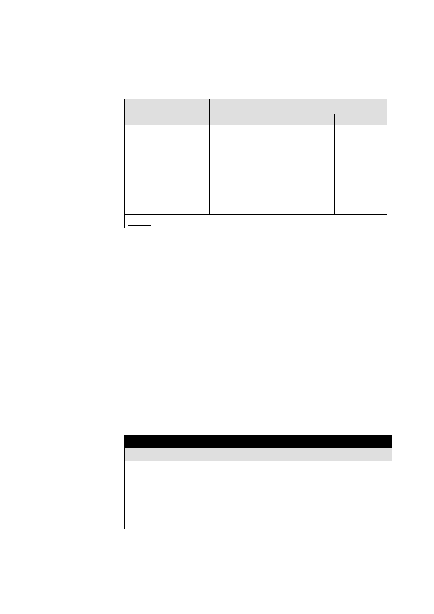
Guidance for the Treatment of Landfill Leachate
Page 64 of 182
Sector Guidance Note IPPC S5.03 – February 2007
2.1.3.6 Evaporation/concentration
Table 2.8:
Operating results from a MSF evaporation plant treating
leachate at Uttigen, Switzerland
Determinand
Leachate
Effluent
Range of values
Mean value
COD (mg/l)
4060
40 – 116
61
BOD
5
(mg/l)
305
32
17
Ammoniacal-N (mg/l)
2000
4 – 17
9
Conductivity (µS/cm)
12000
42 – 302
140
pH-value
-
4 - 7.8
6.5
AOX (µg/l)
4500
2 9- 67
54
Phenols (µg/l)
-
208 – 450
320
Notes:
Units as shown; - = no data; from Hofstetter, 1990
Environmental issues and concerns
As with reverse osmosis, the process is a concentration step, and identical
considerations apply to the disposal of the concentrate that is produced,
involving considerable cost.
Electricity consumption, for production of vacuums etc, is typically about
10 KWh per m
3
treated. Costs of heat energy will vary, depending on
availability of local waste heat sources. The plant itself is very expensive –
treatment of 250 m
3
/d will involve a plant costing in excess of £2.5M.
Very large quantities of acid and other chemicals are involved, for example,
about 1 percent by volume of 32 percent w/v hydrochloric acid (i.e. 10 litres of
acid per m
3
of leachate treated). This is not only expensive, but if leachate is
concentrated by a factor of 20 times, will in itself result in concentrations of
chloride in excess of 60,000 mg/l of chloride in the concentrate sludge. Typical
chloride levels of 2,000 mg/l in leachate would raise total concentrations of
chloride in sludge to greater than 10 percent by weight.
Operation is relatively labour-intensive, estimated at 2 hours per day for a
skilled operator.
A further key issue is the control of air emissions from the process.
Indicative standards for physical treatment processes
General
1. The standards for storage and treatment vessels are detailed section 2.1.1
2. The standards for storage of raw materials are detailed in section 2.1.2
3. Leachate of some composition, particularly those from more recent wastes
will cause foaming in stripping plants. Foaming should be countered by
routine addition of antifoam agents.
4. Odour and ventilation is addressed in section 2.2.6.

Guidance for the Treatment of Landfill Leachate
Page 65 of 182
Sector Guidance Note IPPC S5.03 – February 2007
5. Fugitive emissions to air are addressed in section 2.2.4
Methane stripping
1. Adequate volumes of air shall be used during the stripping process to keep
concentrations of methane present in the exhaust gas well below explosive
levels.
2. Close control of the air input during the operation of the plant can be used to
reduce the precipitation of inorganic scale within the stripping reactors, or
downstream pipework. Provision of additional flow capacity in the
downstream pipework increases the period between pipe cleaning
operations.
Removal of Ammoniacal-N by Air Stripping
1. If raising pH-value is used to increase the process efficiency, high dosages
of alkali (typically in the range 3-8 kg of Ca(OH)
2
per m
3
treated) will be
required, and effluent may subsequently require acid neutralisation before
discharge, such dosing should be undertaken using automatic calibrated in-
line dosing pumps.
2. Operation at elevated temperatures will reduce alkalinity requirements, use
can be made of landfill gas, or of waste heat from landfill gas power
generation schemes an option. In the event that the operator proposes to
use energy other than waste heat to raise the process temperature
consideration should be give to alternative uses of this energy to determine
which represents BAT.
3. Precipitation of inorganic and organic materials may cause scaling and
clogging problems if packed towers are used for the stripping operation, and
may result in a requirement for removal and disposal of sludges.
Procedures must be in place that ensures that the identification of any
scaling or clogging within the pack tower and for subsequent management
and disposal of sludge arising.
4. Where relatively high effluent concentrations of ammoniacal-N are accepted
(e.g. 100-200 mg/l), greatly reduced aeration rates can be achieved.
Leachate will require secondary biological treatment if effluent discharge to
watercourses is an option, the removal of ammoniacal-N to very low levels
during stripping can result in nitrogen deficiency in secondary stages of
treatment
5. Release of ammonia gas in exhaust air may be controlled by thermal
destruction in a landfill gas flare. When considering the utilisation of landfill
gas flares for thermal destruction the impact on the emissions from the flare
have to be considered.
Reverse osmosis
1. The return of retenate to the landfill shall only take place if:
Any predicted change in leachate concentration has been assessed;
it must be shown that the landfill is adequately engineered so that the
concentrate does not cause pollution (particular attention should be
given to the impact on groundwater, an appropriate source term should
be modelled in the landfill site’s hydrogeological risk assessment);
it must be shown that the leachate treatment system can adequately
treat any predicted change in leachate quality resulting from the return
of the concentrate;
chemicals essential to the effective operation of the plant should be
selected so as not to compromise the disposal of the concentrate; and
the leachate originated from the landfill site (i.e. no imported leachate).
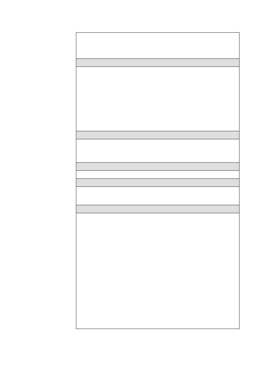
Guidance for the Treatment of Landfill Leachate
Page 66 of 182
Sector Guidance Note IPPC S5.03 – February 2007
2. Ideally the soluble contaminants should be stabilised before disposal.
3. The chemicals used in membrane backwashing should be selected to
ensure they will not cause damage to the RO membrane.
Sand filtration
1. The application of sand filters to raw leachate is rarely appropriate and is
more applicable as tertiary treatment.
2. The optimum application is to reduce levels of solids from up to 200 or 300
mg/l, down to below about 30 or 50 mg/l. They are likely to represent BAT
for such applications at landfills which are relatively large, fully-manned and
treat consistent and relatively high flows (>100 m
3
/d) of leachate.
3. Efficiency is directly related to levels of suspended solids in water being
treated, although they can deal well with variable influent quality. Volumes
of backwash water generated are also related to solids being removed.
Backwash water should be reused by returning it directly into the biological
treatment reactor.
Dissolved air flotation
1. Optimisation of coagulation processed is key to improving effluent quality.
Therefore automated on-line dosing of chemical equipment should be used.
Manual dosing should be avoided as it reduces the accuracy of addition
rates and can lead to overdosing.
Activated carbon – general
1. Activated carbon should be regenerated.
Activated carbon – powdered
1. In the event that the PAC may be contaminated with persistent organic
pollutants and no suitable regeneration facility is available incineration
preferably with energy recovery should be used.
Activated carbon – granular
1. GAC filtration systems generally demand a relatively low level of suspended
solids in incoming effluent, which may require a specific additional treatment
stage (e.g. DAF, reed bed, etc), following initial biological treatment
processes.
2. The presence of multiple contaminants can impact overall performance. For
example (hypothetical), if the GAC is required to reduce overall COD in
effluent to a specific level, and also to remove a specific contaminant
completely, such as a relatively non-biodegradable pesticide (e.g.
isoproturon), then it cannot be presumed that removal efficiencies for each
contaminant will necessarily decline in a similar manner. Bench tests are
therefore essential to estimate carbon usage for mixtures.
3. Treatment costs can be high if used on effluents with high COD values,
following biological treatment, or if very low final effluent values are
required. Since biological effluents from treatment of leachates containing
high (>1500 mg/l) concentrations of ammoniacal-N can contain up to or
greater than 1000 mg/l of soluble, intractable COD, (e.g. see Robinson et al,
2003), this can make polishing of such effluents relatively expensive.
4. In general, smaller molecules are adsorbed less well, as are highly water-
soluble compounds.

Guidance for the Treatment of Landfill Leachate
Page 67 of 182
Sector Guidance Note IPPC S5.03 – February 2007
5. Spent carbon, possibly containing some hazardous compounds which, have
been concentrated within it (e.g. chlorinated compounds and pesticides), will
require regeneration (and safe destruction of these compounds) at one of
only 2 or 3 locations in the UK. Proximity of the treatment plant to such a
location may impact on costs for carbon, and overall unit costs of treatment.

Guidance for the Treatment of Landfill Leachate
Page 68 of 182
Sector Guidance Note IPPC S5.03 – February 2007
2.1.4 Chemical treatment processes
2.1.4.1 Chemical oxidation processes
Chemical oxidation processes are potential treatment options for the removal of
specific organic and inorganic pollutants from landfill leachates, but are unlikely to
provide full treatment of the wide range of contaminants present in typical samples.
Oxidation involves the loss of one or more electrons from the element being
oxidised – the electron acceptor being another element, including an oxygen
molecule, or a chemical species containing oxygen, such as hydrogen peroxide,
ozone, or some other electron acceptor.
In practice, the application of such processes will be restricted by cost, by the rate
of reaction possible (oxidation rates for some organic compounds may be too
slow), and by the availability of alternative treatment processes for specific
contaminants.
In a complex wastewater such as leachate, the amount of chemical oxidant
required in practice, is generally greater than the theoretical mass calculated from
first principles. This results from a number of reasons, including incomplete
oxidant consumption, and lack of specificity of the desired process – oxidant also
being consumed by other chemical reactions. Oxidation reactions are often pH-
dependent, and control of pH-values may be an important consideration.
For treatment of landfill leachates, a limited range of oxidants have found
successful application to date, primarily ozone or hydrogen peroxide. Use of
others has been limited by concerns about formation of toxic reaction by-products
– for example, chlorine and chlorine compounds giving rise to trihalomethanes, or
other halogenated compounds.
Nevertheless, in specific situations, chemical oxidation processes can provide
particular benefits – for example, at elevated pH-values, cyanide can be oxidised
to carbon dioxide and nitrogen using sodium hypochlorite (e.g. see Patterson,
1985). It is likely, therefore, that chemical oxidation processes will find only
occasional application in leachate treatment, and then to deal with individual and
site-specific circumstances. Ozonation and use of hydrogen peroxide will probably
account for most applications.
For all reagent-based chemical oxidation processes, the storage and handling of
potentially hazardous chemicals must be addressed and considered, and
appropriate standards of design and care applied. If extreme conditions are
required within a treatment reactor, then high standards of control and containment
become even more important safety considerations.
Because of their nature, advanced chemical oxidation processes continue to be
developed experimentally. Examples include wet air oxidation, and
electrochemical oxidation systems. At the time of drafting, these have not been
successfully applied to leachate treatment, but over coming decades it is possible
that novel processes may be developed and need to be considered.

Guidance for the Treatment of Landfill Leachate
Page 69 of 182
Sector Guidance Note IPPC S5.03 – February 2007
2.1.4.1.1. Ozonation
General information
Ozonation is well established as a treatment technology for drinking waters, or in
swimming pools, for which it is used as a disinfectant, to degrade substances of
concern, and to enhance the performance of other treatment processes. Although
not so widely employed for the treatment of sewage or industrial wastewaters,
ozonation has much to offer in specific circumstances.
Ozone is the strongest practical oxidant available for waste water treatment, and is
used for:
Oxidation of organic materials, especially recalcitrant organic compounds,
to enhance their removal by subsequent treatment – especially in biological
processes;
Disinfection;
Taste, odour, and colour removal;
As a pre-oxidant stage to enhance removal of turbidity and algae within
subsequent treatment processes; and
Precipitation of iron and manganese.
Capital costs of ozone treatment are relatively high (typically £250K to £350K to
dose 150 mg/l into 200 m
3
of effluent per day), due to the high cost of equipment
for ozone generation. Electricity comprises the majority of operational costs, which
can also be high, especially for stronger leachates.
Ozonation should be seen as an expensive polishing option, appropriate only in
specific circumstances for leachate treatment, such as complete destruction of less
biologically-degradable pesticides in final effluents. Nevertheless, case studies in
the UK and overseas have demonstrated that such systems can operate reliably
on landfill sites.
Process overview
Ozone itself (O
3
) is an allotrope of oxygen, and is a gas at normal temperatures
and pressures. It is relatively unstable, having a half-life of less than 30 minutes in
distilled water at 30°C (Reynolds, 1982). Because of this instability, ozone must
therefore be generated at the point of use, by passing air or pure oxygen between
oppositely charged plates. The gases having been pre-dried to a dew point lower
than about -40°C. Pure oxygen feed is generally only more cost-effective than air
for ozonation systems that are required to generate more than 1 tonne of ozone
per day. For smaller systems (typical leachate applications will require less than
50 kg of ozone per day) then air is generally used.
Once produced, air containing enhanced concentrations of ozone gas is bubbled
through the water to be treated in a column, using a bubble diffuser system.
Generally, a batch system of treatment is preferred, with a contact time of between
15 minutes and an hour.
Ozone transfer occurs as fine bubbles containing ozone and air (or oxygen) that
rise slowly inside the column, contacting the contaminated water phase. Correct
ozone dosage to achieve required oxidation of specific compounds is generally
determined using small-scale treatability studies. Pesticides, aromatics, alkanes
and alkenes are examples of compounds readily and successfully treatable by
ozonation.

Guidance for the Treatment of Landfill Leachate
Page 70 of 182
Sector Guidance Note IPPC S5.03 – February 2007
Ozone treatment is generally only appropriate as a polishing step in the treatment
of landfill leachates, following extensive biological pre-treatment to remove
degradable organic compounds that might otherwise result in excessive
consumption of ozone. Removal of suspended solids from water being treated is
also essential for efficient treatment. In addition, ozonation is best applied to well
nitrified or low ammonia containing effluents, since to some extent ammonia also
competes for ozone with the organic compounds being targeted.
Environmental issues and concerns
Unlike chlorine, the use of ozone for effluent polishing does not result in excessive
formation of trihalomethanes. However, as well as directly degrading some
organic compounds, ozone can increase the degradability of organic compounds,
resulting in increased levels of BOD in effluents. These can then readily be
degraded efficiently, using passive processes such as reed bed polishing.
Particularly during treatment of landfill leachates, ozonation can result in
generation of very reactive brominated intermediate compounds (e.g. bromal, =
tribromoacetaldehyde). Experience has demonstrated that although such
compounds exhibit significant toxicity, they are readily and completely degraded
within an appropriately designed reed bed polishing system.
There is only one example of a full-scale leachate treatment plant in the UK where
ozonation has been applied as a polishing stage for leachate treatment. In that
instance, ozonation was applied to meet extremely stringent effluent toxicity
criteria, before discharge into a very sensitive receiving watercourse. The plant
has operated successfully since 1994, particularly for the complete removal of a
number of pesticides, such as mecoprop and isoproturon, in biologically pre-
treated leachate. Experience has been that ozonation generally only provides
between 10-15 percent removal of residual hard COD, and that if COD levels in
final effluent are a major issue, then alternative polishing processes, such as
activated carbon, may be more appropriate.
Where removal of adsorbable organic halogens (AOX) is an issue, ozonation has
been shown to be capable of reducing values of AOX from up to 3 mg/l, to below
0.5 mg/l (e.g. see Kaulbach, 1993). Costs of such treatment, where required, must
be compared with those of alternative processes, such as activated carbon
adsorption.
Although variants of ozonation, involving combined treatment with hydrogen
peroxide (H
2
O
2
), and/or Ultra Violet irradiation, are capable of providing increased
oxidation potential by the enhanced generation of hydroxyl radicals, such
processes have rarely been applied to treatment of landfill leachates.
2.1.4.1.2 Hydrogen Peroxide
General information
Hydrogen peroxide (H
2
O
2
) is a strong oxidising agent generally supplied as a 35%
w/v solution. Use of hydrogen peroxide has found many applications to oxidise
contaminants in industrial wastewaters. In the presence of a catalyst, such as iron,
hydrogen peroxide (H
2
O
2
) generates hydroxyl radicals (*OH), which can react with
reduced compounds and specific organics.
For leachate treatment, peroxide treatment systems have ranged from very simple
drip feed dosing into open leachate lagoons, through pumped dosing into the inlet
of large recirculation pumps, to fully engineered dosing systems into mixed
reactors. Dosing of hydrogen peroxide has sometimes also been incorporated
within simple methane stripping systems for leachate (see earlier), in order to meet
discharge consents for entry of leachate into the public sewer. Hydrogen peroxide
and potassium permanganate have also been used successfully to treat odorous

Guidance for the Treatment of Landfill Leachate
Page 71 of 182
Sector Guidance Note IPPC S5.03 – February 2007
leachates for short periods by turning the leachates aerobic and reducing the
potential to cause odour.
Process overview
In leachate treatment, hydrogen peroxide oxidation has been applied principally to
oxidise sulphide, although experience from other industries has shown that many
other contaminants which might be found in leachates can also potentially be
treated (eg phenols, sulphite, cyanide, formaldehyde, etc).
For oxidation of sulphide, reactions depend on pH-value as below:
(a)
acidic or neutral pH
H
2
O
2
+ H
2
S
→
2H
2
O + S
Reaction time 15-45 minutes (much quicker if catalysed by Fe
2+
)
(b) Basic
pH
4H
2
O
2
+ S
2-
→
SO
4
2-
+ 4H
2
O
Reaction time 15 minutes
Sulphide levels have been successfully managed at between 10 – 20 UK landfill
sites, either to control odours, or to comply with limits for discharges of leachates
into sewers. Under the optimum pH-value conditions of neutral or slightly acid, the
reaction of peroxide and sulphide is relatively specific, and chemical requirements
of about 25 percent greater than those predicted in equation (a) have generally
proved to be appropriate, with a reaction time of about 30 minutes. Laboratory
trials may be valuable in optimising chemical dosing rates.
Environmental issues and concerns
Principle concerns over Hydrogen Peroxide relate to storage and handling issues
and ensuring that in the event of a spillage adequate controlls are in place (spill
kits, bunding and training) to protect sensitive environmental receptors.
Hydrogen Peroxide is a strong oxidising agent and as such must not be allowed to
come into contact with incompatable materials.
2.1.4.2 Precipitation/coagulation/flocculation
2.1.4.2.1 Chemical precipitation of metals
General information
It has been widely demonstrated that, with the exception of levels of zinc in
acetogenic leachate samples, concentrations of heavy metals in leachates from
landfills containing primarily household wastes are relatively low. Typical values
are generally lower than those measured in samples of domestic sewage, and far
lower than levels of metals being treated at sewage treatment works, where inputs
of industrial effluent have also been received. Median values for key metals in
leachates from modern large landfills, with high waste input rates (including co-
disposal sites and sites receiving industrial and commercial wastes) are reported
below, and are compared with values for non-industrial crude sewage (in mg/l,
after Robinson, 1995).

Guidance for the Treatment of Landfill Leachate
Page 72 of 182
Sector Guidance Note IPPC S5.03 – February 2007
Table 2.9
Median values for key metals in leachate
Metal
Acetogenic
leachate
Methanogenic
leachate
Domestic sewage
(range of values)
Chromium
0.12
0.07
0.01 - 0.17
Nickel
0.23
0.14
0.01 - 0.19
copper
0.07
0.07
0.06 - 0.50
zinc
6.85
0.78
0.10 - 1.65
cadmium
0.01
<0.01
0.001 - 0.03
lead
0.30
0.13
0.03 - 0.395
Additionally, significant removal of some of these metals in leachate (e.g. zinc,
chromium, copper) has been reported during aerobic biological treatment (see
Robinson and Knox, 2001).
On this basis, chemical treatment to reduce concentrations of metals is unlikely to
be widely required, in particular at landfills which, receive significant inputs of
household wastes, or where leachates are treated biologically before discharge.
Precipitation and other reactions within an anaerobic landfill will generally reduce
the mobility of heavy metals significantly.
Nevertheless, if specific circumstances require such metal removal, chemical
precipitation processes are widely employed for this purpose, for effluents in a
wide variety of industries, and could readily be adopted.
Although specific treatment processes for removal of heavy metals from landfill
leachates will only occasionally be necessary, and have rarely been provided at
UK landfill sites, on occasions when specific features of landfills require such
treatment, there is a wealth of experience and data to allow appropriate systems to
be designed (e.g. see Eckenfelder, 1989).
Difficulties may arise from the relatively low concentrations of heavy metals
present in leachates, reducing the cost-effectiveness of the process, and also
where there is a need to remove mixtures of metals, and these have different
optimum pH-values for precipitation.
Process overview
Precipitation is widely employed for the removal of concentrations of heavy metals
from industrial wastewaters, and although many chemicals have been used (e.g.
hydrated lime, quicklime, magnesium hydroxide, sodium hydroxide), hydrated lime,
Ca (OH)
2
, has been most widely used, and is generally the cheapest. Heavy
metals are usually precipitated as the hydroxide through the addition of alkali, to a
pH-value at which solubility of the metal of interest is minimised. Several metals
are amphoteric, and exhibit a point of minimum solubility, below or above which
solubility will increase and removal will reduce. Examples are chromium (pH value
7.5), and zinc (pH value 10.2).
Although many leachates have been shown to contain organic complexing agents,
which have potential to interfere with metal removal (especially at relatively low
concentrations in leachate), excellent removal of metals has nevertheless been
reported by many authors (e.g. Knox, 1983; Bjorkman and Mavinic, 1977; Chian
and DeWalle, 1977).

Guidance for the Treatment of Landfill Leachate
Page 73 of 182
Sector Guidance Note IPPC S5.03 – February 2007
All precipitation processes are very strongly influenced by the pollution matrix of
specific leachates, and as a consequence, laboratory and pilot-scale trials are
essential if the process is to be optimised, and efficient treatment systems are to
be developed, and operated to achieve effluent limits reliable and cost-effectively.
The wastewater treatment industry has extensive experience which enables it to
provide appropriate precipitation processes, which take advantage of a range of
chemical phenomena including co-precipitation and adsorptive co-precipitation, so
that residual metal solubility levels far below theoretical solubility limits for simple
metal salts can commonly be achieved. Similarly, appropriate subsequent
treatment stages of flocculation, sedimentation and clarification; can be optimised
based on experience. Volumes and handling characteristics of precipitated
sludges are frequently at least as important as economic factors, in final selection
or optimisation of precipitation processes.
Environmental issues and concerns
Principal environmental issues relate to the correct storage of chemicals, correct
dosing to prevent excessive use of reagents and sludge disposal. Sludge may be
dewatered to facilitate handling transportation and disposal. Typically, disposal will
by landfill depending on Landfill Regulations limitations.
2.1.4.2.2 Coagulation and flocculation
General information
Chemical coagulation and flocculation are used for the removal of waste materials
present in suspended or colloidal form. Colloids represent particles typically within
a size range from 1.0nm to 0.1nm (10
-7
to 10
-8
cm). These particles do not settle
out on standing, and are not readily removed by conventional physical treatment
processes.
Coagulants, usually salts of iron or aluminium, are added at controlled pH-values
to form solid precipitates termed floc, which contain the colloidal particles, and can
then be separated out using conventional solid, liquid separation processes. The
process of flocculation encourages floc growth by gentle mixing, to suite the
subsequent separation process being used.
Process overview
In leachate treatment at UK landfills, full-scale coagulation/flocculation systems
have rarely, if ever, been applied to the raw leachates, and only occasionally to
biologically pre-treated effluents.
Nevertheless, in other countries such as Germany, coagulation and flocculation
processes are more widely applied to both raw and treated leachates, and
extensive experience is available. Common applications have included:
• Removal of turbidity and colour from biological treatment effluents;
• Reduction in COD values associated with colloidal materials;
• Removal of powdered activated carbon (PAC) in effluent polishing (see
separate section);
• Reduction in suspended solids concentrations, to protect subsequent
treatment stages – e.g. in activated carbon columns.

Guidance for the Treatment of Landfill Leachate
Page 74 of 182
Sector Guidance Note IPPC S5.03 – February 2007
Coagulant aids, often polyelectrolyte compounds, may be added to enhance
coagulation by promoting the development of large, rapid-setting flocs.
Polyelectrolytes are high-molecular-weight polymers that form bridges between
particles or charged flocs, when added at low concentrations (1-5 mg/l) in
conjunction with alum or ferric chloride.
The key to successful coagulation and flocculation is detailed jar-scale, laboratory
testing, to establish the optimum pH-value and coagulant dosing for treatment of a
specific leachate or effluent. Good mixing at the point of chemical dosing, and
tight control of coagulant dose and pH-value are essential, as is optimisation of the
physical process of floc formation. In large-scale wastewater treatment processes,
sophisticated feedback controls are routinely used, which may be more difficult to
apply to smaller leachate treatment applications.
Environmental issues and concerns
Principal environmental issues relate to the correct storage of chemicals, correct
dosing to prevent excessive use of reagents and sludge disposal. Sludge may be
dewatered to facilitate handling transportation and disposal. Typically, disposal will
by landfill depending on Landfill Regulations limitations.
2.1.4.2.3 Electrochemical Processes
General information
The future use of electrochemical processes in the treatment of leachate has been
suggested. This section provides a brief overview of the processes involved for
information purposes and does not make any recommendations or specify
standards.
Three electrochemical processes may be applicable to the treatment of
wastewater, electro-coagulation/electro-flocculation, and electro-oxidation.
Electrodes placed in the leachate can be aluminium or iron. On the application of
an electric current coagulants are formed by the dissolution of the anode.
Hydrogen gas is generated at the cathode and oxygen at the anode. Aluminium
and iron precipitates that form can be removed by sedimentation or by flotation.
Flotation of low density flocculated particles is aided by the generation of hydrogen
and oxygen. The oxidation of organic substances and ammoniacal-N can occur
directly at the anode or indirectly from the degradable content of the solution.
Indicative BAT requirements for chemical treatment processes
General
1. Storage and handling of chemicals is covered in section 2.1.2.
2. The use of automated on-line dosing of chemical equipment. Manual dosing
should be avoided as it reduces the accuracy of addition rates and can lead to
overdosing.
Ozonation
1. The ozone contactor should be designed for efficient adsorption that minimises
ozone in the off-gas. Any ozone remaining in the off-gas from the diffusion
system must be destroyed before release into the atmosphere. Destruction of
excess ozone is accomplished readily using thermal, catalytic, or other
processes. (Threshold limit value (TLV) for repeated exposure of workers to

Guidance for the Treatment of Landfill Leachate
Page 75 of 182
Sector Guidance Note IPPC S5.03 – February 2007
ozone is 0.21 mg/m
3
in air.)
2. By decomposing to oxygen as it reacts, ozone provides an environmentally
preferable alternative to halogenated oxidants (e.g. chlorine), adsorption (e.g.
activated carbon) or even reverse osmosis in some circumstances.
3. Typical power consumption for generation of ozone from air or oxygen is 16
kWh and 8 kWh respectively, per kg of ozone produced. Process design must
take into account the additional costs involved in purchase and safe handling
of liquid oxygen, and also the significant costs of pumping liquids and dosing
these with the ozone-enhanced air.
Hydrogen Peroxide treatment
1. Hydrogen Peroxide has several key advantages over alternative chemical
oxidising agents for leachate treatment applications. It does not produce toxic
chlorinated by-products, nor any increase in AOX, as does chlorine and
hypochlorite, nor does it increase salinity.
2. Hydrogen Peroxide can provide a temporary buffer against septicity, in the
form of dissolved oxygen, because it readily decomposes to water and oxygen
within the environment.
Chemical precipitation of metals
1. Lime or other chemicals used as part of the process must be selected on the
basis of a high purity to avoid introducing other potential contaminants into the
process, or reducing the reactivity of the reagents.
2. Equipment used to prepare and dose slurries is critical to operation of the
process and must be subject to a preventative maintenance programme.
3. Certain chemicals e.g. lime are susceptible to the effects of moisture and must
be stored in dry conditions.
4. Treated water will be of much higher pH-value than the feed water, and may
require addition of acids to reduce pH-values to suitable levels for discharge or
subsequent treatment.
5. The precipitated metals will be settled out of the water stream, and will be
contained within the waste sludges generated by the process, which will also
exhibit high pH-values. Handling and disposal of waste sludges must be
appropriate to the nature and hazard of the metals present. These sludges
may be designated as a hazardous waste.
Precipitation /coagulation/flocculation
1. Chemical coagulants, flocculants, and pH-control chemicals may be hazardous
and require appropriate precautions in use and storage. Cationic and anionic
flocculants can be very toxic to fish and their storage and use should ensure
appropriate containment and dosing.
2. The main risk to the process is lack of appropriate control, resulting in failure to
meet treatment objectives. A high degree of process control should be
maintained at all times.
3. The optimum pH-value and coagulant dosing should be established by
detailed laboratory testing prior to operation.
Wyszukiwarka
Podobne podstrony:
więcej podobnych podstron