
C102964-0 Page 1 of 10
02.04.2008
© The information contained in this document is the sole property of Steerprop Ltd. any reproduction or disclosure in part or whole without written permission is prohibited.
DOC-1017-1
Voltage Supply
Service Manual
Revision history:
REV. DATE MODIFIER DESCRIPTION
0 2.4.2008
AaNi Created
A
B
C
D
E
F

C102964-0 Page 2 of 10
02.04.2008
© The information contained in this document is the sole property of Steerprop Ltd. any reproduction or disclosure in part or whole without written permission is prohibited.
DOC-1017-1
1
CONTROL VOLTAGE SUPPLY......................................................................................................... 3
2
AC SUPPLY ............................................................................................................................................ 4
3
24 VDC SUPPLY FOR ELECTRIC AND CONTROL ...................................................................... 5
3.1
P
OWER SUPPLY VARIATIONS FOR EQUIPMENT CONNECTED TO
D.C.
SYSTEMS
................................ 5
3.2
P
OWER SUPPLY VARIATIONS FOR EQUIPMENT CONNECTED TO BATTERY POWER SUPPLY
.............. 5
4
24 VDC SUPPLY FOR INSTRUMENTS (ALARM TRANSDUCERS ETC.)................................. 6
4.1
P
OWER SUPPLY VARIATIONS FOR EQUIPMENT CONNECTED TO
D.C.
SYSTEMS
................................ 6
4.2
P
OWER SUPPLY VARIATIONS FOR EQUIPMENT CONNECTED TO BATTERY POWER SUPPLY
.............. 6
5
VOLTAGE SUPPLY ALARMS AND FAILURES............................................................................. 7
5.1
C
ONTROL SYSTEM VOLTAGE ALARM
............................................................................................... 7
5.2
C
ONTROL VOLTAGE ALARM TEST
.................................................................................................... 9
5.2.1
Starting ........................................................................................................................................ 9
5.2.2
Main control voltage alarm (AC supply) ..................................................................................... 9
5.2.3
Main control voltage alarm F1 circuit breaker ........................................................................... 9
5.2.4
Back-up control voltage alarm F2 circuit breaker .....................................................................10
5.2.5
Automatic change-over to back-up supply..................................................................................10
5.2.6
Indication system voltage alarm F3 circuit breaker...................................................................10
C102964-0 Page 3 of 10
02.04.2008
© The information contained in this document is the sole property of Steerprop Ltd. any reproduction or disclosure in part or whole without written permission is prohibited.
DOC-1017-1
1 C
ONTROL VOLTAGE SUPPLY
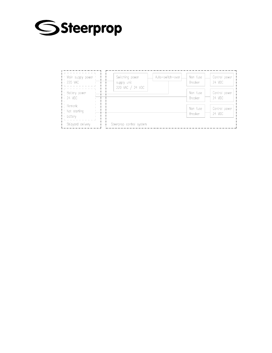
The Steerprop control voltage supply is redundant and straightforward system. The
main control system is supplied from single phase AC network and from a back-up
battery. The indication and back-up control systems are supplied from battery. The
battery should be separate from the engines starting batteries.

C102964-0 Page 4 of 10
02.04.2008
© The information contained in this document is the sole property of Steerprop Ltd. any reproduction or disclosure in part or whole without written permission is prohibited.
DOC-1017-1
2 AC
SUPPLY
Permanent frequency variations ..........................................± 5 % of nominal
Permanent voltage variations....................................... + 6/- 10 % of nominal
Frequency transients (5 s duration) ...................................± 10 % of nominal
Voltage transients (1,5 s duration) .....................................± 20 % of nominal

C102964-0 Page 5 of 10
02.04.2008
© The information contained in this document is the sole property of Steerprop Ltd. any reproduction or disclosure in part or whole without written permission is prohibited.
DOC-1017-1
3 24
VDC
SUPPLY FOR ELECTRIC AND CONTROL
3.1 P
OWER SUPPLY VARIATIONS FOR EQUIPMENT CONNECTED TO
D.C.
SYSTEMS
Voltage tolerance continuous ............................................ 21.6 … 26.4 VDC
Voltage transients cyclic variation .......................................± 5 % of nominal
Voltage ripple ....................................................................± 10 % of nominal
3.2 P
OWER SUPPLY VARIATIONS FOR EQUIPMENT CONNECTED TO
BATTERY POWER SUPPLY
When using low voltage battery supply, the charging equipment, batteries and cables
are to keep the voltage at equipment terminals within below defined tolerances of the
nominal voltage during charging and discharging. The battery is not allowed to connect
to engine starting systems.
Voltage tolerance .................................................................. 19.2 … 30 VDC
Voltage transients (up to 2 s duration) ..............................± 20 % of nominal
Provisions are to be made for preventing reverse current from the battery through the
charging device.

C102964-0 Page 6 of 10
02.04.2008
© The information contained in this document is the sole property of Steerprop Ltd. any reproduction or disclosure in part or whole without written permission is prohibited.
DOC-1017-1
4 24
VDC
SUPPLY FOR INSTRUMENTS
(
ALARM
TRANSDUCERS ETC
.)
4.1 P
OWER SUPPLY VARIATIONS FOR EQUIPMENT CONNECTED TO
D.C.
SYSTEMS
Voltage tolerance continuous ............................................ 21.6 … 26.4 VDC
Voltage transients cyclic variation .......................................± 5 % of nominal
Voltage ripple ....................................................................± 10 % of nominal
4.2 P
OWER SUPPLY VARIATIONS FOR EQUIPMENT CONNECTED TO
BATTERY POWER SUPPLY
When using low voltage battery supply, the charging equipment, batteries and cables
are to keep the voltage at equipment terminals within below defined tolerances of the
nominal voltage during charging and discharging. The battery is not allowed to connect
to engine starting systems.
Voltage tolerance .................................................................. 18 … 31.2 VDC
Voltage transients (up to 2 s duration) ..............................± 25 % of nominal
PROVISIONS ARE TO BE MADE FOR PREVENTING REVERSE CURRENT FROM THE
BATTERY THROUGH THE CHARGING DEVICE.

C102964-0 Page 7 of 10
02.04.2008
© The information contained in this document is the sole property of Steerprop Ltd. any reproduction or disclosure in part or whole without written permission is prohibited.
DOC-1017-1
5 V
OLTAGE SUPPLY ALARMS AND FAILURES
5.1 C
ONTROL SYSTEM VOLTAGE ALARM
Control system voltage alarm can be due to following reasons:
Control system 220 V supply
PLC 24 VDC supply
24 VDC back-up supply
Voltage supply for remote indicators
Circuit breaker for fans and brakes at BFU
Circuit breakers at SCU
If the circuit breaker or switch is open, find out the reason. If the breaker or switch is
opened by means, check, if you can close it or not.
If the reason is failure, find the real reason and repair it before closing the circuit
breaker.

C102964-0 Page 8 of 10
02.04.2008
© The information contained in this document is the sole property of Steerprop Ltd. any reproduction or disclosure in part or whole without written permission is prohibited.
DOC-1017-1
FAULT EFFECT TEMPORARY
ACTION
CAUSE REMEDY
Vessel switchboard
supply switch is open
Close switchboard
switch
Wire is broken, short
circuit or connection
is open
Repair cabling or
wiring failure
Control system
220 VAC supply
Control system
transfer
automatically to
back-up supply.
Not needed.
Converter AP02 is
broken
Replace the converter
Supply protection
circuit breaker F1
blown
Close circuit breaker
PLC power supply
broken
Replace PLC power
supply
Wire is broken, short
circuit or connection
is open
Repair cabling or
wiring failure
PLC 24 VDC
supply (Indication
HI17 does not lit)
-The main control
of one propulsor
does not work
-Propeller motor
rpm set is going
to zero
If you can’t
operate with one
propulsor, use
back-up control
for this propulsor.
Control voltage switch
is open.
Close control switch
Supply protection
circuit breaker F2
blown
Close circuit breaker
Vessel switchboard
supply switch is open
Close switchboard
switch
24 VDC back-up
supply failure
If the 220 VAC
main supply is
working, main
control will
continue operate
normally
Not needed. Be
careful.
Wire is broken, short
circuit or connection
is open
Repair cabling or
wiring failure
Supply protection
circuit breaker F3
blown
Close circuit breaker
Vessel switchboard
supply switch is open
Close switchboard
switch
24 VDC supply
for remote angle
indicators failure
The display does
not operate.
Follow the
mechanical
display at
propulsor.
Wire is broken, short
circuit or connection
is open
Repair cabling or
wiring failure

C102964-0 Page 9 of 10
02.04.2008
© The information contained in this document is the sole property of Steerprop Ltd. any reproduction or disclosure in part or whole without written permission is prohibited.
DOC-1017-1
5.2 C
ONTROL VOLTAGE ALARM TEST
This test procedure includes all control voltages supplies for propulsor
Main control voltage from AC supply, circuit breaker F1
Back-up control voltage 24 VDC, circuit breaker F2
Indication voltage supply 24 VDC, circuit breaker F3
5.2.1 S
TARTING
Supply switch SS01 OFF
Local control SC01 selected
5.2.2 M
AIN CONTROL VOLTAGE ALARM
(AC
SUPPLY
)
Check, that AC supply to SMU is on. Measure with digital multimeter, that
the voltage between terminals L1 and L2 is over 90 VAC. Also the green
running LED should be on at AP02.
Turn supply switch SS01 ON
You can verify the voltage level between terminals 222 and 223. It should
be over 22 VDC.
5.2.3 M
AIN CONTROL VOLTAGE ALARM
F1
CIRCUIT BREAKER
Switch OFF the circuit breaker F1 from SCU.
Control voltage alarm will appear.
Control system alarm will appear.
Low steering speed and wrong direction alarm will appear.
Lubrication oil pressure alarm will appear.
Lubrication oil start level alarm will appear.
Lubrication oil high temperature alarm will appear.
Switch circuit breaker F1 ON.
Main control starts and remote control is operational.
Alarms will disappear.

C102964-0 Page 10 of 10
02.04.2008
© The information contained in this document is the sole property of Steerprop Ltd. any reproduction or disclosure in part or whole without written permission is prohibited.
DOC-1017-1
5.2.4 B
ACK
-
UP CONTROL VOLTAGE ALARM
F2
CIRCUIT BREAKER
Verify the voltage level between terminals 202 and 203. It should be over
22 VDC.
Turn the propulsor with local steering LCR / SC02.
You can verify the voltage level between terminals 202 and 203. It should
be over 22 VDC.
Switch OFF the circuit breaker F2 from SCU.
Control voltage alarm will appear.
Switch circuit breaker F2 ON.
Alarm will disappear.
5.2.5 A
UTOMATIC CHANGE
-
OVER TO BACK
-
UP SUPPLY
Switch OFF the AC supply from vessel switchboard.
The control voltage supply goes automatically to back-up supply.
The relay KM1 change the supply to back-up
You can verify the voltage level between terminals 222 and 223. It should
be over 22 VDC.
Remote control is still operational.
Control voltage alarm will appear.
Connect the supply from vessel AC supply ON.
The green led at AP02 lit.
The relay KM1 changes the supply to main supply.
You can verify the voltage level between terminals 222 and 223. It should
be over 22 VDC.
5.2.6 I
NDICATION SYSTEM VOLTAGE ALARM
F3
CIRCUIT BREAKER
All angle indicators should go to the same position as the mechanical
indicator at propulsor is.
Turn the propulsor with local steering LCR / SC02. You can see the
indicators following the mechanical indicator.
You can verify the voltage level between terminals 802 and 803. It should
be over 22 VDC.
Switch OFF the circuit breaker F3 from SCU
Control voltage alarm will appear.
Switch circuit breaker F3 ON.
Alarm will disappear.
Wyszukiwarka
Podobne podstrony:
C102968 0 SERVICE LOCAL STEERING
C102960 0 SERVICE SEAL SYSTEM
C102965 0 SERVICE CONTROL UNIT
C102962 A SERVICE TRANSMITTER UNIT
C102961 A SERVICE STEERING GEAR
03 E70 Voltage Supply and Bus WB
03 2 F01 Voltage Supply
579393d1434286492 any interest e60 can bus code hacking 10 e60 voltage supply bus systems
Inverter Negative Voltage Supply using 555 Switching Regulator
SP6FIN 160m HF receiver ECC82 low power supply voltage
A 12kw Switching Mode Power Supply With Free Input Voltage
Low Voltage Power Supply Circuits
więcej podobnych podstron