This copy is a reprint which includes current
pages from Changes 1 and 2.
O P E R A T O R ’ S M A N U A L
F O R
R I F L E , 5 . 5 6 - M M , M 1 6
( 1 0 0 5 - 0 0 - 8 5 6 - 6 8 8 5 )
R I F L E , 5 . 5 6 - M M , M 1 6 A 1
( 1 0 0 5 - 0 0 - 0 7 3 - 9 4 2 1 )
H E A D Q U A R T E R S , D E P A R T M E N T O F T H E A R M Y
F E B R U A R Y 1 9 8 5


TM 9-1005-249-10
C2
CHANGE
NO. 2
HEADQUARTERS
DEPARTMENT OF THE ARMY
W a s h i n g t o n , D C
11 May 1990
Operator’s Manual
for
RIFLE, 5.56-MM, M16
(1005-00-856-6885)
RIFLE, 5.56-MM, M16A1
(1005-00-073-9421)
TM 9-1005-249-10, 11 February 1985, is changed as follows:
Page 2-24. Add the following WARNING before the previous WARNING.
WARNING
With the bolt carrier assembly locked to the rear or in its
forward position, if the weapon is dropped or jarred with a
loaded magazine in place, it could chamber a round.

By Order of the Secretary of the Army:
CARL E. VUONO
General, United States Army
Chief of Staff
Offlclal:
WILLIAM J. MEEHAN II
Brlgadier General, United States Army
The Adjutant General
Distribution:
To be distributed in accordance with DA Form 12-40, block 135, Operator
Maintenance Requirements for Rifle, 5.56 MM, M16, M116A1.


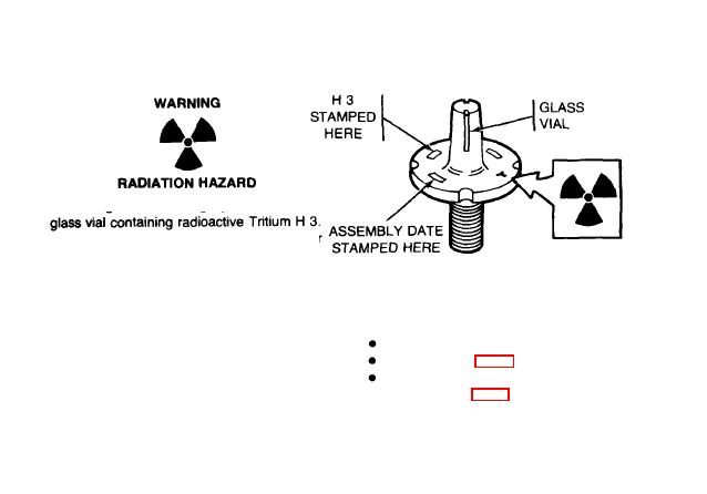
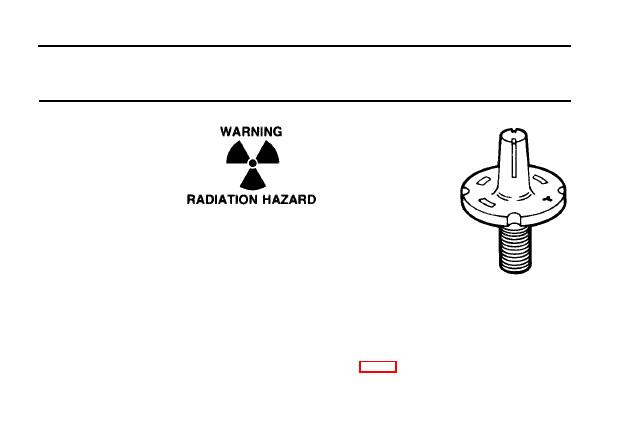
WARNING
All personnel that operate and/or maintain fire control equipment must be aware of the following special
precautions.
TRITIUM (H 3)
Rules and Regulations
Copies of the following rules and regulations are maintained at HQ, AMCCOM, Rock Island, IL 61299-
6000. Copies may be requested or information obtained by contacting the AMCCOM Radiological
Protection Officer (RPO), AUTOVON 793-3482, Commercial (309) 794-3483.
10CFR Part 19- Notices, Instructions and Reports to Workers; Inspections
10CFR Part 20- Standards for Protection Against Radiation
NRC license, license conditions, and license application
a

WARNING (CONT)
Safety Precautions
The radioactive material used in these instruments
IS
tritium gas (H3) sealed in pyrex tubes. It poses no
significant hazard to the repairman when intact. These sources iIlummate the instrumentation for night
operations. Tampering with or removal of the sources in the field
is
prohibited by Federal law. In the event
there
IS
no illumination, notify the local Radlologlcal Protection Officer. Do not attempt to repair or replace
the instrument in the field! If skin contact
IS
made with any area contaminated with tritium, immediately
wash with nonabrasive soap and water.
Identification
Radioactlve self-luminous sources are identified by means of radioactive warning labels (as above)
These labels should not be defaced or removed, and should be replaced immediately when necessary.
Refer to the local RPO or the AMCCOM RPO for instructions on handling, storage, or disposal.
Storage and Shipping
All radioactively illuminated instruments or modules which are defective will be evacuated to a depot
maintenance activity. These items must be placed in a plastic bag and packaged in the shipping container
from which the replacement was taken before evacuation to a higher echelon is made. Spare equipment
must be stored in the shipping container as received until installed on the weapon. Storage of these items
is recommended to be in an outdoor shed type storage or unoccupied building.
FIRST
AID
For further information on first aid, see FM 21-11
b

WARNING (CONT)
To avoid accidental firing,
BE SURE WEAPON IS CLEAR.
Failure to do so could result in serious injury or
death.
Be sure the cam pin is installed in the bolt group. If it isn't, your rifle can still fire and will explode causing
injury or death.
If you're using the blank firing attachment, don't use any other ammmunition except the blank round, M200.
Do NOT
exchange or switch bolt assemblies from one M16/M16A1 to another. It could cause damage to
both you and the rifle.
DON'T OVERHEAT M16/M16A1 RIFLE BARRELS.
Sustained firing of the M16/M16A1 Rifle Will rapidly
raise the temperature of the barrel to a critical point.
Firing 140 rounds, rapidly and continuously, will raise the temperature of the barrel to the
COOKOFF
POINT.
At this temperature, any live round remaining in the chamber for any reason may cook off
(detonate) in as short a period as 10 seconds.
lf the cookoff point (or temperature) is felt possible, weapon should be immediately cleared and allowed to
cool.
Sustained rate of fire for the M16/M16A1 Rifle is 12-15 rounds per minute. This is the actual rate of fire that
a weapon can continue to deliver for an indefinite length of time without serious overheating.
Sustained rate of fire should never be exceeded except under circumstances of extreme urgency
If your bolt fails to unlock and you try to free it by banging the buttstock on the ground, keep clear of the
muzzle.

WARNING (CONT)
If there’s water in the barrel, don’t fire the rifle, It could explode,
If you experience a noticeable difference in sound or recoil, STOP FIRING. Either condition could indicate
an Incomplete propellant burn and a bullet still in the bore. Retract bolt slowly and remove fired cartridge
case. Clear weapon and check for unburned powder grams in the receiver or bore and for a bullet in the
bore. Remove unburned propellant or bullet from bore before resuming firing or barrel could explode. If
bullet is lodged in bore, turn in rifle to the unit armorer,
If rifle stops firing with a live round in the chamber of a hot barrel, remove the round fast. However, during
training, if you cannot remove it within 10 seconds, wait 15 minutes with the rifle pointing in a safe
direction. This way you won’t get hurt by a possible ammunition cookoff, which could happen 10 seconds
after contact with a hot chamber. Clear rifle.
Use only authorized ammunition that
IS
manufactured to US specifications,
Blank ammunition should not be fired toward personnel within 20 feet or less from the muzzle, because
fragments of a closure wad or particles of unburned propellant might inflict injury within that range.
If you go by all the instructions in this book, and perform preventive maintenance (PM), your M16/M16A1
rifle will operate properly. If you’ve done your part and it fails to perform properly, turn in your M16/M16AI
rifle to your unit armorer.

TECHNICAL MANUAL
HEADQUARTERS
DEPARTMENT OF THE ARMY
No. 9-1005-249-01
Washington, DC
11 February 1985
Operator’s Manual
for
RIFLE, 5.56-MM, M16
(1005-00-856-6885)
RIFLE, 5.56-MM, M16A1
(1005-00-073-9421)
REPORTING ERRORS AND RECOMMENDING IMPROVEMENTS
Y
O
u can help improve this manual. If you find any mistakes or if you
know of a way to improve the procedures, please let us know. Mail
your letter or DA Form 2028 (Recommended Changes to Publications
and Blank Forms) direct to: Commander, US Army Armament, Muni-
tions and Chemical Command, ATTN: AMSMC-MAS, Rock Island, IL
61299-6000. A reply will be furnished to you.
*This manual supersedes TM 9-1005-249-10, 1 April 1977,
i n c l u d i n g a l l c h a n g e s .

Section I.
Section Il.
Section Ill.
Section I.
SectIon II.
Section III.
Section IV.
Section V.
Section I.
Section Il.
Section Ill.
Page
INTRODUCTION
General lnformation. . . . . . . . . . . .. .. . . . . . . .. . . . . . . . . . . . . . . . . . . 1-1
Equipment Description. . . . . . . . . .. . . . .. . .. . . . . . . . . . . . . . . . . . . . . ... . . . 1-3
Technical Prlnciples of Operation . .. . . . . . . . . . . . . . . . . .. . . . . . . . . . . . 1-5
OPERATING INSTRUCTIONS
Description and Use of Operator’s Controls and Indicators . . . . . . . . . . . .. .. . . . . . . .2-1
Preventive Maintenance Checks and Servlces(PMCS). . . . . .. . . . . . .. . . . . . 2-4
Operation Under Usual Conditions . . . . . . . .. . . . . . . . .. . . . .. . . . . ...2-13
Assembly and Preparation for Firing . .. . . . . . . . . . . . . . . . . . . . . . . . . ...2-14
Initial Adjustments. . . . . . .. . . . . . . . . . . . . . . . . . . . . . . . . . . . ...2-16
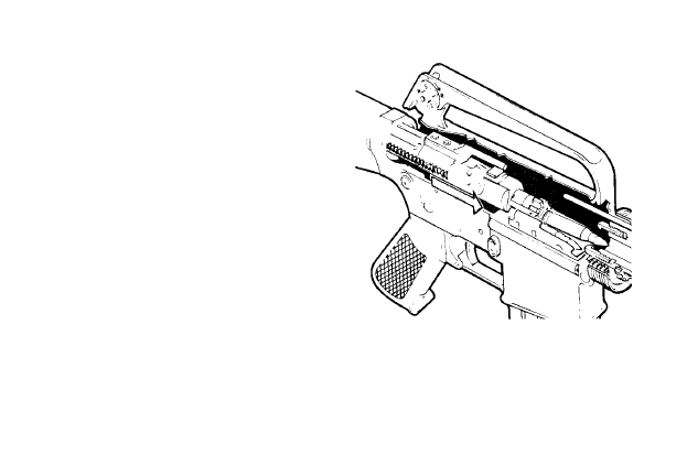
Operating Procedure . . . . . . . . . . . . . . . . . . . . . . . ...2-24
Operation of Auxiliary Equipment .. .. . .. . .. . . . . . . . . ...2-36
Operation Under Unusual Conditions 2-40
Nuclear, Bilogical, and Chemical (NBC) . . . . . . . . . . . . . . . . . . . . . . . . . . ...2-43
MAINTENANCE INSTRUCTIONS
Lubrication Instructions . . . . . . . . . . . . . . . . . . . . . . . . . 3-0
Troubleshooting Procedures, . . .. . . . . . . . . . . . . . . . . . . . . . . . . . . . .3-0
Maintenance Procedures . . . . . . . . . . . . . . . . . . . . . . . . . . . . .3-14
Field-Stripping M16/M16A1 Rifle . . . . . . . . . . . . . . . . . . . . . . . . . . . . . ...3-14
Reassembly of M16/M16A1 Rifle . . . . . . . . . . . . . . . . . . . . . ...3-41
Functional Check . . . . . . . . . . . . . . . . . . . . . . .3-49

Page
APPENDIX A. REFERENCES . . . . . . . . . . . . . . . . . . . . . . . . . . . . . . .. A-0
APPENDIX B. COMPONENTS OF END ITEM AND BASIC ISSUE ITEMS LIST B-1
APPENDIX C. ADDITIONAL AUTHORIZATION LIST . . . . . . . . . . . . . . . . . . . . . . . . . . .. C-l
APPENDIX D. EXPENDABLE/DURABLE SUPPLIES AND MATERIALS LIST . D-1
APPENDIX E. STOWAGE GUIDE . . . . . . . . . . . . . . . . . . . . . . . . . .. E-1
ALPHABETICAL INDEX . . . . . . . . . . . . . . . . . . . . . . . . . . . . . . . . . . . . . . . . lndex 0
iii
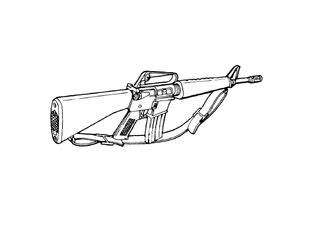
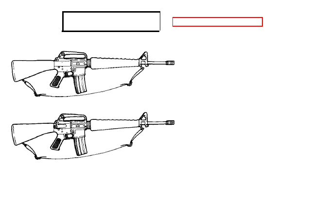
M16A1 RIFLE
1-0

INTRODUCTION
Section I. GENERAL INFORMATION
1-1. SCOPE.
a. Type of Manual: Operator’s
b. Model Number and Equipment Name: M16/M16A1 5.56-mm Rifle.
c. Purpose of Equipment: To provide personnel an offensive/defensive capability to engage
targets in the field.
1-2. MAINTENANCE FORMS AND RECORDS.
Department of the Army forms
and procedures used for equipment maintenance will be those prescribed by DA PAM 738-750,
The Army Maintenance Management System (TAMMS).

1-3. REPORTING EQUIPMENT IMPROVEMENT RECOMMENDATIONS
(EIR’s).
lfyourrifle needs improvement,let usknow. Sendusan EIR. You, theuser, arethe
only one who can tell us what you don’t like about your equipment. Let us know why you don’t like
the design or performance. Put it on an SF 368 (Quality Deficiency Report). Mail it to us at
Commander, US Army Armament, Munitions and Chemical Command, ATTN: AMSMC-QAD,
Rock Island, IL 61299-6000. We’ll send you a reply.

Section II. EQUIPMENT DESCRIPTION
1-4. EQUIPMENT CHARACTERISTICS, CAPABILITIES, AND FEATURES.
a. The M16/M16A1 rifle is lightweight, air cooled, gas operated, magazine fed, and shoulder
fired.
b. The rifle may be fired with selector lever in the automatic or semiautomatic position.
c. It also provides personnel an offensive/defensive capability to engage targets in the field.
1-5. DIFFERENCES BETWEEN MODELS.
The 5.56-mm Rifle M16 does not con-
tain the forward assist assembly contained on the 5.56-mm Rifle Ml 6A1. Both models may be
equipped with the low light level sight assembly.

1-6. EQUIPMENT DATA.
Weight:
Rifle M16, without cartridge magazine and sling . . . . . . . . . . . . . . . . . . . . . . . . . . . . 6.351b
Rifle M16A1, without cartridge magazine and sling . . . . . . . . . . . . . . . . . . . 6.55 lb
Overall length:
Rifle w/flash suppressor . . . . . . . . . . . . . . . . . . . . . . . . . . . . . . . . . . . . . . . . . . . . ..39 in.
Rifle w/bayonet-knife . . . . . . . . . . . . . . . . . . . . . . . . . . . . . . . . . . .. . . . . . . . . . . . . . . . . ..44.25 in.
Maximum rate of fire:
Semiautomatic . . . . . . . . . . . . . . . . . . . . . . . . . . . . . . . . . . . . . . . . . . . . . ..45/65 rounds/m
Automatic . . . . . . . . . . .. . . . . .. . . . . . . . . . . . . . . ..150/200 rounds/m
Maximum effective range . . . . . . . . . . . . . . . . . . . . . . . . . . . . . . . . . . . . . . . . . . ..460 meters
1
2
3
4
5
6
7
8
9
Section Ill. TECHNICAL PRINCIPLES OF OPERATION
NOTE
Magazine may be loaded with bolt
assembly open or closed.
Place selector lever on SAFE.
Insert loaded caftridge magazine in
magazine well and chamber a round.
Face the target, move the selector lever from
SAFE to SEMI or AUTO, and place the rifle
to your shoulder.
Aline the front and rear sight with the target
and squeeze the trigger.
Squeezing the trigger releases the firing pin
and allows it to impact the primer on the
round.
The primer ignites the propellant in the round.
Gas from the burning propellant pushes the projectile along the barrel of the rifle.
The rifling in the barrel causes the projectile to rotate which provides stability during flight to the
target.
When round reaches approximate end of barrel, expanding gases from burning propellant
pass out through gas port and into gas tube. Gas goes into bolt carrier assembly, ejects old
cartridge, and chambers a new round.
RIGHT SIDE
2-0

OPERATING INSTRUCTIONS
Section I. DESCRIPTION AND USE OF OPERATOR’S
CONTROLS AND INDICATORS
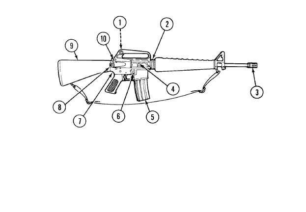
2-1. M16/M16A1 MECHANICAL CONTROLS.
REAR SIGHT (1) - zeros weapon and engages targers to 460 meters.
HAND GUARD SLIP RING (2) - keeps hand grards in place.
FLASH SUPPRESSOR (3)- reduces the amount of flash from muzzle when weapon is fired.
EJECTION PORT COVER (4) - protects upper receiver from foreign matter when weapon
IS
not in use. Keep
port cover closed when not used.
CARTRIDGE MAGAZINE (5) - supplies 30 rounds of ammunition to the weapon.
MAGZINE CATCH BUTTON (6) - releases cartridge magazine (5) from weapon when pushed.
LOWER RECEIVER AND EXTENSION ASSEMBLY (7)- provides firing control for the weapon and provides
storage for basic cleaning materials.
FORWARD ASSIST ASSEMBLY (M16A1 ONLY) (8) - ensures that bolt is fully forward
and locked.
SHOULDER GUN STOCK ASSEMBLY (9) - stabilizes rifle.
CHARGING HANDLE ASSEMBLY (10) - cocks weapon when preparing to fire or clearing weapon.
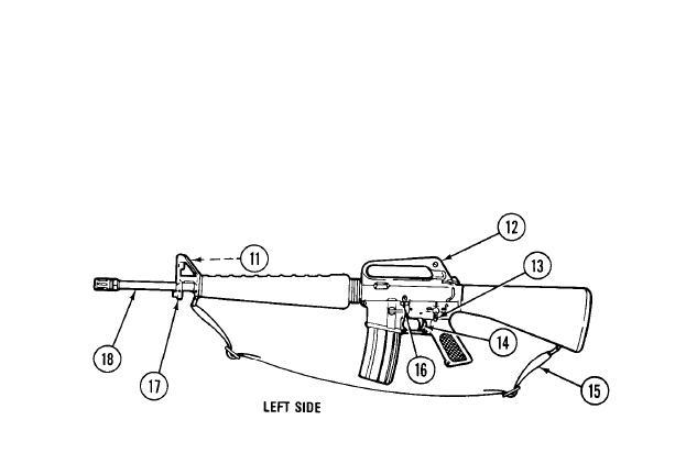
2-1. M16/M16A1 MECHANICAL CONTROLS (CONT).
FRONT SIGHT POST (11) - adjustable for elevatlon
CARRYING HANDLE ASSEMBLY (12) - provides the means for hand-carrying the rifle,
SELECTOR LEVER (13) - arms the rifle in SEMI or AUTO or safes the rifle.
TRIGGER (14) - controls the firing of the weapon
SMALL ARMS SLING (15) - provides the means for shoulder-carrying the weapon,
BOLT CATCH (16) - moves the key and bolt carrier assembly forward when depressed,
BAYONET STUD (17) - holds bayonet in place
UPPER RECEIVER AND BARREL ASSEMBLY (18) - directs the projectile upon firing.
2-2

2-2. THROW AWAY THE WHITE GLOVES FOR RIFLE INSPECTIONS.
a. CLP will leave a film, or layer, of Teflon that builds up over a period of time This is one of the
benefits of using CLP, especially in combat, where you might not have time to lube your rifle as
often as you think it needs it. So, throwaway your white gloves. But carry a rag with you to wipe
your harnds when you inspect rifles because your fingers are going to get, a little slick if your troops
have used the right amount of CLP on their rifles.
b. Now, if you are going to inspect rifles the following day, give your troops a few minutes to wipe
their rifles down again. Remember, CLP is a cleaner and it never stops working. So, overnight
while the Teflon has been forming a film for lubrication, the cleaning solvents in the CLP have been
at work in the nooks and crannies (actually in the pores of the metal) seeking out carbon and firing
residue.
2-3. ARMORY AND ORDNANCE INSPECTORS.
You professionals who inspect
weapons and armories should be the experts who are out there insisting that a light coat of CLP be
kept on rifle metal parts at all times. Since it’s always at work cleaning, expect “a little” carbon to be
present. If there is doubt as to whether the rifle is or was cleaned properly or not, field-strip it. As the
expert, you should be able to tell from plenty of other indicators, e.g., carbon under extractor, on
firing pin or bolt, etc. whether or not the rifle was cleaned, Iubed, and preserved properly.
2-3

Section Il. PREVENTIVE MAINTENANCE CHECKS
AND SERVICES (PMCS)
2-4. GENERAL.
Perform after (A) operations PMCS if: you are the assigned operator and
the weapon has been stored in the arms room and not used for a period of 90 days, or you have
been issued the weapon for the first time.
NOTE
An inactive weapon is a weapon, whether assigned or not assigned to an individual,
that is stored in an arms room for a period of 90 days. Performance of normal cleaning
(PMCS) of an inactive weapon will be performed every 90 days,
a. Before You Operate. Always keep in mind the CAUTIONS and WARNINGS. Perform your
before (B) PMCS.
b. While You Operate. Always keep in mind the CAUTIONS and WARNINGS. Perform your
during (D) PMCS.
c. After You Operate. Be sure to perform your after (A) PMCS.
d. If Your Equipment Fails to Operate. Troubleshoot with proper equipment. Report any
deficiencies to organizational maintenance using the proper forms. See DA PAM 738-750.
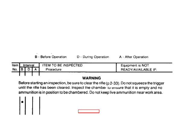
2-5. PMCS PROCEDURES.
The PMCS table lists those required checks and services
to be performed to ensure accurate performance of the rifle. When recording results of PMCS,
entries in the PMCS item No. column shall be used for the TM Item No. column on DA Form 2404.
The third column lists the item to be inspected. The fourth column contains conditions that make
the rifle not ready/availabie because of inability to perform its primary combat mission. If anything
looks wrong, and you cannot correct it yourself, notify organizational maintenance,
OPERATOR PREVENTIVE MAINTENANCE CHECKS AND
SERVICES (PMCS)
1
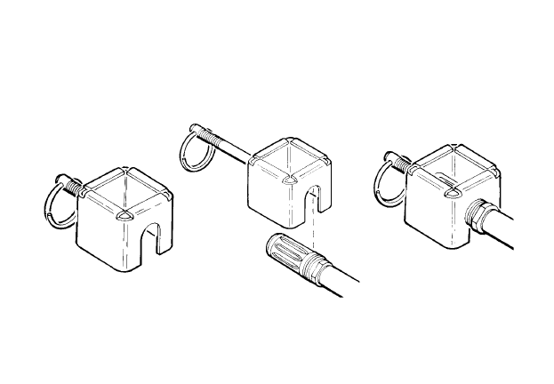
ESSENTIAL TOOLS AND EQUIPMENT. Check the authorized tools
and equipment and auxiliary equipment for completeness and
serviceability. (See appendix C, section Il.)
OPERATOR PREVENTIVE MAINTENANCE CHECKS AND
SERVICES (PMCS) (CONT)
B- Before Operation
D- During Operation
A After Operation
MAINTENANCE READINESS. Clear and clean bore with dry swab
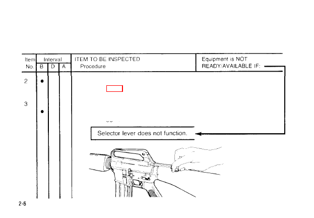
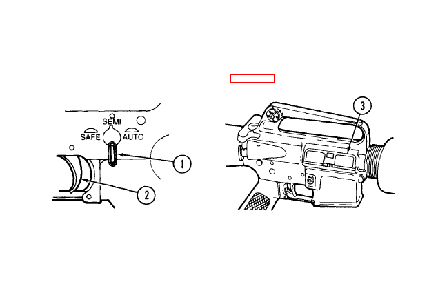
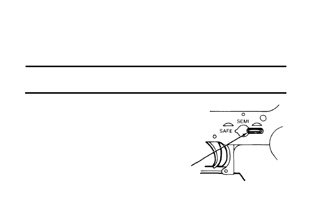
SELECTOR LEVER FUNCTIONING.
a. Cock the rifle and place the selector lever in SAFE position. Squeeze
the trigger; the hammer should not fall.
OPERATOR PREVENTIVE MAINTENANCE CHECKS AND
SERVICES (PMCS) (CONT)
B -
Before Operation
D- During Operation
A - After Operation
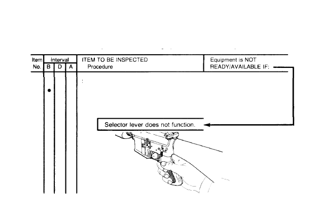
SELECTOR LEVER FUNCTIONING (CONT)
b. SEMI/Posifiorr. Squeeze tigger; hammer should fall. Hold triggerto
the rear and recock rifle. Release the trigger. You should hear a click
as you release the trigger. Again squeeze trigger; hammer should
fall.
2-7
OPERATOR PREVENTIVE MAINTENANCE CHECKS AND
SERVICES (PMCS) (CONT)
B- Before Operation
D- During Operation
A- After Operation
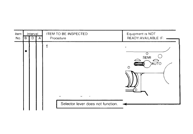
SELECTOR LEVER FUNCTIONING (CONT).
c. AUTO Position. Cock the rifle.
Squeeze the trigger; hammer
should fall Hold trigger to the rear
and cock the rifle. Release the
pressure on the trigger and
squeeze it to the rear again. The
hammer should not fall because it
should have fallen when the bolt
was allowed to move forward dur-
ing the cocking sequence.
2-8
OPERATOR PREVENTIVE MAINTENANCE CHECKS AND
SERVICES (PMCS) (CONT)
B - Before Operation
D - During Operation
A - After Operation
2-9
OPERATOR PREVENTIVE MAINTENANCE CHECKS AND
SERVICES (PMCS) (CONT)
B - Before Operation
D - During Operation
A - After Operation
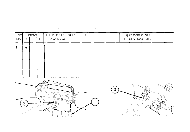
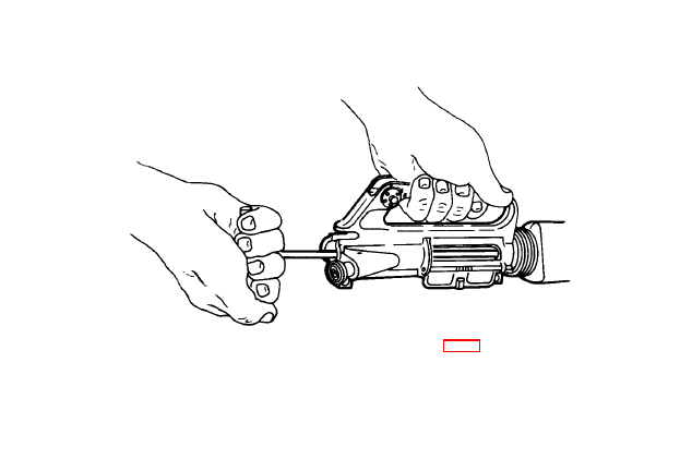
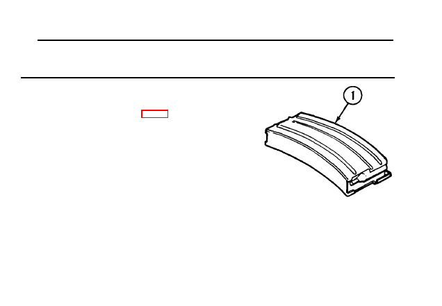
MAGAZINE CATCH (FUNCTION).
Insert magazine (l) into the well,
The magazine catch should hold the magazine in place. Pressing the
magazine catch button (2) should release the magazine. To adjust the
magazine catch, use cleaning rod to press in on the magazine catch
button until the left side of the magazine catch (3) sticks out beyond the
receiver. To tighten, turn the magazine catch clockwise; to loosen, turn it
counterclockwise.
2-10
OPERATOR PREVENTIVE MAINTENANCE CHECKS AND
SERVICES (PMCS) (CONT)
B -
Before Operation
D - During Operation
A - After Operation
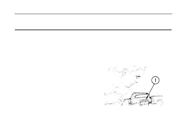
VISUAL INSPECTION OF RIFLE.
WARNING
Be sure rifle is clear. Refer to pages 2-33 thru 2-35.
Look the rifle over for missing or damaged parts. Report missing or
damaged parts to emit armorer.
2-11
OPERATOR PREVENTIVE MAINTENANCE CHECKS AND
SERVICES (PMCS) (CONT)
B - Before Operation
D - During Operation
A - After Operation
PERIODIC INSPECTION OF RIFLE. Periodically check rifle to make
sure It’s clean and there
IS
no foreign material in bore. If foreign material
is in bore, clean bore (p 3-29).
MAINTENANCE PERFORMED DURING FIRING OPERATIONS.
WARNING
Be sure rifle
IS
clear. Refer to pages 2-33 thru 2-35.
Clean and Iubricate rifle after firing approximately 200 rounds of
ammunition (p 3-28).
MAINTENANCE OF RIFLE AND EQUIPMENT. Field-strip rifle(p3-14).
Clean and lubricate according to pages 3-28 thru 3-33. Disassemble
magazine. Clean and Iubricate according to pages 3-26 and 3-27. Clean
and lubricate bayonet, scabbard, and bipod. Report all damaged or
missing parts to unit armorer.
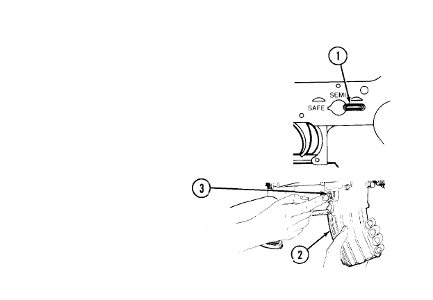
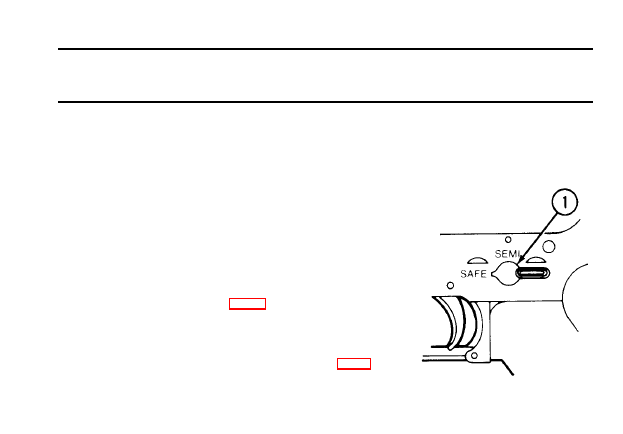
Section Ill. OPERATION UNDER USUAL CONDITIONS
2-6. PREPARATION FOR STORAGE IN ARMS ROOMS.
WARNING
Be sure rifle is clear. Refer to pages 2-33 thru 2-35
1 Place selector lever (1) on SEMI
2 Close ejection cover (3) and
and squeeze trigger (2) to uncock
place in rack.
rifle.
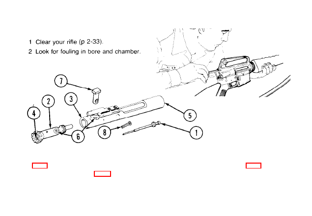
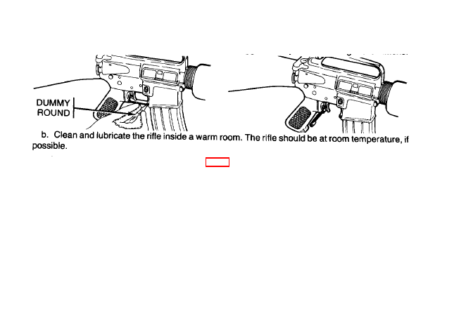
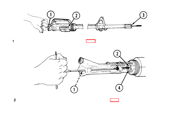
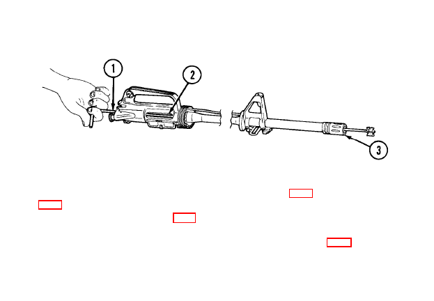
2-7. ASSEMBLY AND PREPARATION FOR FIRING - CLEAN
AND LUBRICATE.
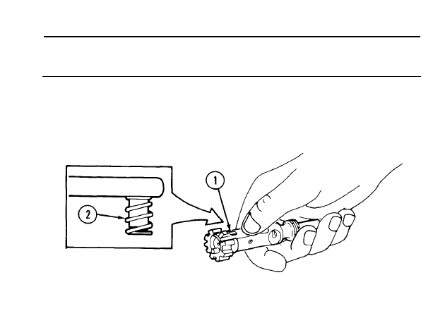
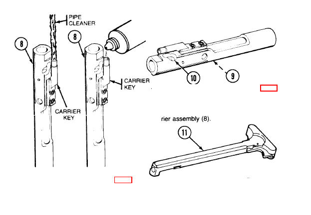
3 Remove and disassemble (p 3-17) bolt carrier assembly and clean carbon and oil from firing
pin (1) and all surfaces of bolt assembly (2) and bolt carrier assembly (3) with dry swabs (item 5,
app D). Clean firing pine hole (4) and bolt carrier key (5) with pipe cleaner (item 2, app D). Lightly
coat with CLP (item 1, app D). Pay special attention to bolt cam pin area (6). Lightly lube bolt cam
pin (7) and firing pin retaining pin (8).
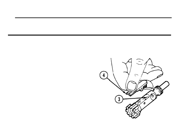
4
5
6
CAUTION
Don’t bend or flex cleaning rod.
“Swab out” (from chamber to muzzle). Make sure swab (item 5, app D) goes all the way through
flash suppressor.
Clean and lubricate lugs (p 3-29).
Reassemble and install bolt carrier assembly (p 3-45).
2-15
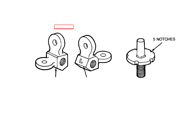
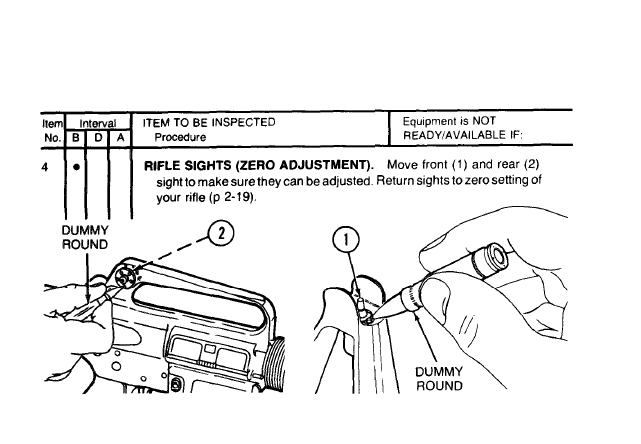
2-8. INITIAL ADJUSTMENTS - STANDARD DAYLIGHT SIGHT SYSTEM.
NOTE
See page 2-20 for adjusting front and rear sights.
UNMARKED
APERTURE
APERTURE
MARKED L
FRONT SIGHT
REAR SIGHT
1 REAR SIGHT - Has two apertures for range.
●
Use the unmarked aperture for targets from 0 -300 meter.
●
Use the aperture marked L for targets from 300-400 meters.
2 FRONT SIGHT - Has five notches of elevation per revolution.
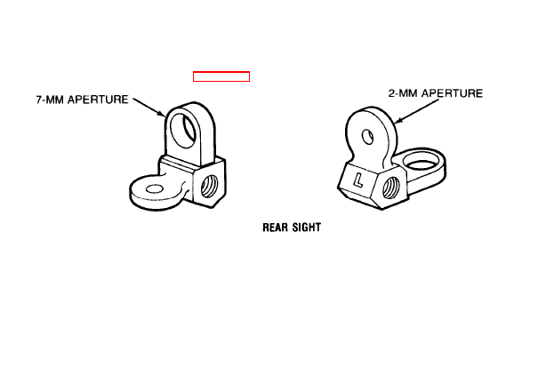
2-9. INITIAL ADJUSTMENTS - LOW LIGHT LEVEL SIGHT SYSTEM.
NOTE
See page 2-21 for adjusting the sights.
1 Use the low light level sight system when visibility is limited. Not every rifle will have this sight
system.
2 REAR SIGHT - Has two apertures.
• Use 7-mm rear sight aperture (unmarked aperture) for night firing and when visibility is
limited.
• Use 2-mm rear sight aperture (aperture marked L) to zero the weapon and to hit targets Up to
460 meters under normal conditions.
2-17
2-9. INITIAL ADJUSTMENTS - LOW LIGHT LEVEL SIGHT SYSTEM
(CONT).
WARNING
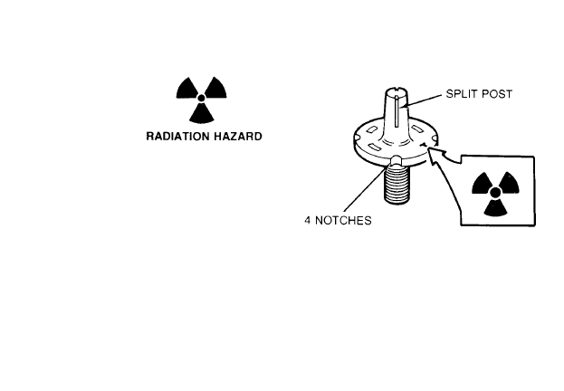
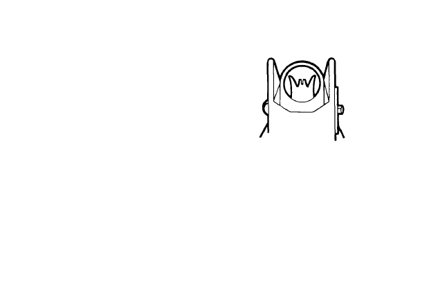
The front sight post contains a small glass vial of
radioactive Tritium H 3. Take care not to bump,
abuse, tamper or alter the post in any manner.
3
2-18
FRONT SIGHT
CAUTION
Do not blacken or soot-up the front sight,
FRONT SIGHT - Has only four notches of elevation per revolution, Split post holds vial of
Iuminous material. Material can be seen from two sides only. If you cannot see the vial after
zeroing, turn the sight one click down for use during periods of limited visibility.
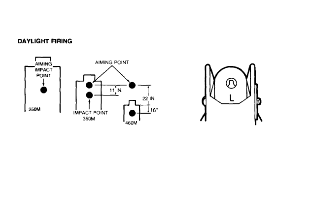
2-10. INITIAL ADJUSTMENTS - BATTLESIGHT ZERO.
NOTE
To zero the rifle, adjust the front sight (elevation) and the rear sight (windage) so that
you can hit aiming point at a given range.
1
2
3
Battlesight zero is that setting on the M16’s sights which will cause the point of aim and strike of
the bullet to be the same at 250 meters.
When using the L-marked aperture, the path of the bullet will cross the line of sight at 25 meters.
Hence, zeroing is now conducted with point of aim and point of impact being the same.
The 25 meter zero target (NSN 6920-01-167-1392) has complete zeroing instructions printed
on its face. The target is printed on both sides: one side is printed for the standard sights and the
other side is printed for use with the low light level sight system. The grid printed on each target is
set up so that one click of elevation of windage is equal to one block change in elevation
or windage.
2-19
2-11. INITIAL ADJUSTMENTS - SIGHT ADJUSTMENT (LOW LIGHT
LEVEL AND STANDARD DAYLIGHT SYSTEMS).
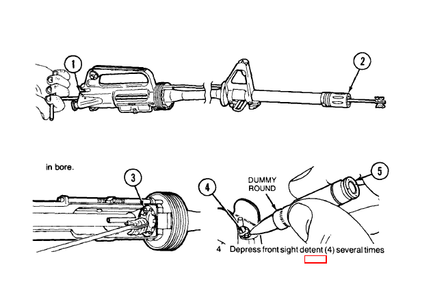
REAR SIGHT To adjust windage, depress detent and rotate drum to direction you want:
1
2
3
To move point of impact to right, turn drum
clockwise in directlon of arrow and letter R
To move left, move drum counterclockwise
Each notch moves the point of impact of bullet
as Indicated in chart
FRONT SIGHT To adjust elevation,
depress detent and rotate post:
1 To raise strike of bullet, rotate post in the
direction of arrow marked up
2 Reverse the direction of rotation to Iower strike
of bullet
3 Each notch moves the point of impact of bullet
as indicated in chart
IMPACT (1 CLICK)
D I S T A N C E
STANDARD SYSTEM
LOW LIGHT LEVEL SIGHT SYSTEM
AT
0.7cm (17/64 in. )
0.9cm (23/64 in. )
25 meters
2.8cm (1-3/32 in. )
3.5cm (1-3/4 in. )
100 meters
5.6cm (2-13/64 in.)
7.0cm (2-3/4 in. )
200 meters
I
2-12. INITIAL ADJUSTMENTS - USING LOW LIGHT LEVEL
SIGHT SYSTEM.
1 Use aperture marked L.
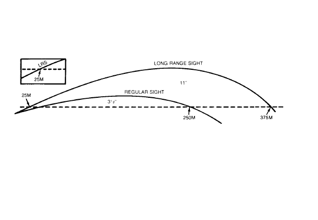
2 Effective range is 250 meters (original battlesight zero); beyond that use hold-off (aiming above
desired point of impact).
3 Aim about 11 inches above top of target at 350 meters and about 22 inches above top of target at
460 meters.
4 To become and remain proficient, practice hold-off,
2-12. INITIAL ADJUSTMENTS - USING LOW LIGHT LEVEL
SIGHT SYSTEM (CONT).
NIGHT AND LIMITED VISIBILITY
5
6
7
8
9
Use unmarked (7-mm) aperture
Use daylight hours procedure to obtain
good sight picture.
After detecting target, aline sight by center-
ing top of lminous portion of front sight post
within 7-mm aperture on target, and fire.
Under certain light conditions, you can see front sight post, but you can’t determine whether you
are looking through, above, or to the side of rear sight aperture.
Practice positioning stock against shoulder and looking through rear aperture.
2-22
2-13. INITIAL ADJUSTMENTS - CARE AND CLEANING OF FRONT SIGHT.
HANDLING AND CARE
CLEANING OF FRONT SIGHT POST
The low light level front sight post has a small
Take care not to bump, abuse, alter or tamper
with the post in any manner.
CAUTION
CAUTION
DO NOT use a wire brush to clean the sight.
Do not blacken or soot-up the front sight.
Clean front sight post with:
NOTE
Toothbrush
Frequently check the sight post for damage. If
damage is evident or suspected, have sight
Swabs (item 5, app D)
Cleaner, Lubricant and Preservative
post checked by the unit armorer.
2-23
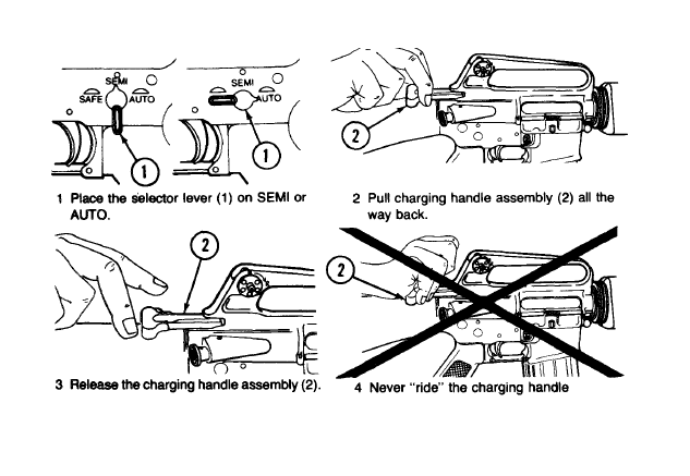
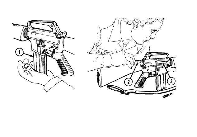
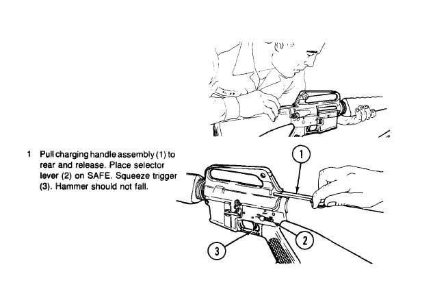
2-14. OPERATING PROCEDURE - LOADING.
1 Pull charging handle assembly (1) rear-
ward, lock bolt, and release charging
handle. Place selector lever (2) on SAFE.
2 Pull charging handle assembly (1 ) rearward
and check to see that chamber is clear, Re-
lease charging handle assembly,
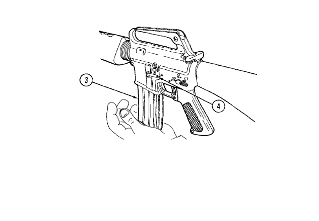
NOTE
Magazine may be loaded with bolt assembly open or closed.
3 Push upward on cartridge magazine (3) until magazine catch (4) engages and holds cartridge
magazine.
4 Tap upward to make sure cadridge magazine is seated correctly.
2-25
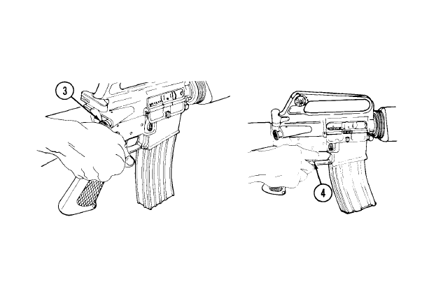
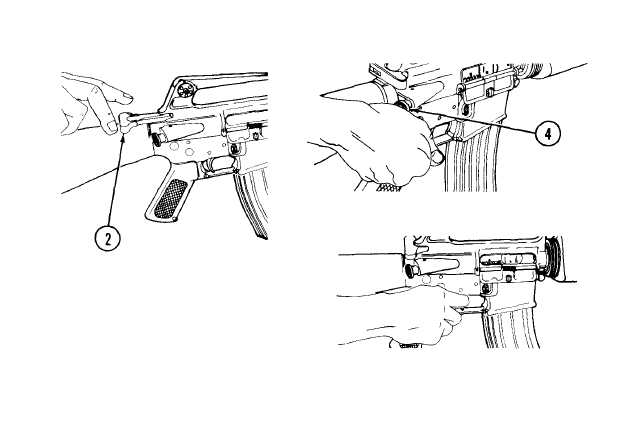
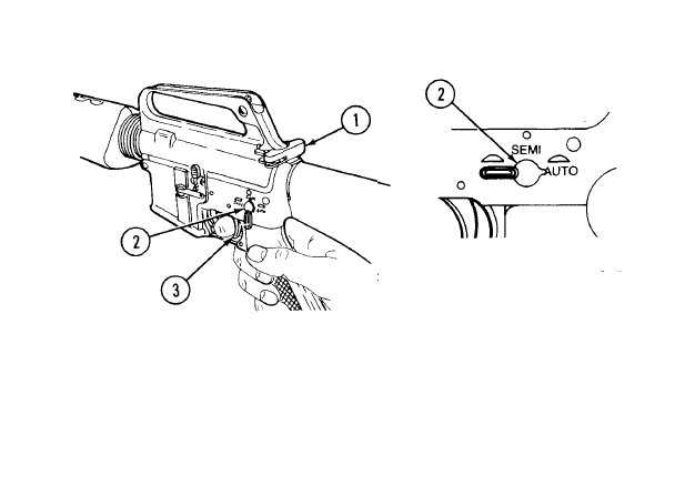
2-15. OPERATING PROCEDURE- CHAMBERING AND FIRING A ROUND.
3 Move selector lever (3) to SEMl or AUT0.
4 Squeeze the trigger (4) and fire.
2-26
BOLT ASSEMBLY CLOSED
assembly (2). Let it go on its own.
2-27
2-15. OPERATING PROCEDURE - CHAMBERING AND FIRING A
ROUND (CONT).
BOLT ASSEMBLY CLOSED (CONT)
5 Tap forward assist assembly (3) to
6 Squeeze the trigger (4) and fire.
ensure bolt is fully forward and
locked (M16A1 only).
2-28
2-16.OPERATINGPROCEDURE-IMMEDIATE ACTION.
1 Slap upward on cartridge
magazine (1) to make sure it’s
properly seated.
2 Pull charging handle assembly (2) all the way back.
Observe ejection of case or cartridge. Inspect
chamber (3) and check for obstruction. If chamber is
not clear, apply remedial action (p 2-31)
2-29
2-16. OPERATING PROCEDURE-
3 Release charging handle assembly (2) to
feed new round. (Don’t ride the charging
handle assembly (2).)
IMMEDIATE ACTION (CONT).
4 Tap forward assist assembly (4) (Ml 6A1
only).
5 Now shoot. If it won’t fire, look for the trouble
and apply remedial action (p 2-31).
2-30
2-17. OPERATING PROCEDURE - REMEDIAL ACTION.
WARNING
If rifle stops firing with a live round in the chamber of a hot barrel, remove the round
fast. However, during training, if you cannot remove it within 10 seconds, wait 15
minutes with the rifle pointing in a safe direction This way you won’t get hurt by a
possible ammunition cook-off, which could happen 10 seconds after contact with a hot
chamber. Clear the rifle.
2 If a cartridge case is in the chamber, tap
out with a cleaning rod.
NOTE
If your rifle still fails to fire, check
1 Check for jammed cartridge case.
troubleshooting.
2-31

2-18. PROJECTILE LODGED IN BORE.
WARNING
If an audible “pop” or reduced recoil is experi-
enced during firing, immediately cease fire. Do
not apply immediate action.
WARNING
Be sure bolt carrier assembly is closed (forward).
If barrel is hot, wait 15 minutes for barrel and
extension assembly to cool so you won’t be hurt
by an ammunition cook-off.
1 Remove cartridge magazine, lock bolt, and return charging
handle (p 2-33).
2
2-32
CAUTION
If projectile is lodged in bore, do not attempt to
remove it. Turn weapon in to organizational
maintenance.
Visually inspect and/or inserf a cleaning rod into bore to ensure there is not a projectile lodged in
bore.
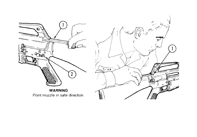
2-19. OPERATING PROCEDURES - CLEARING YOUR RIFLE.
WARNING
To avoid accidental firing, always look into chamber after
clearing weapon to make sure it does not contain a round.
1 Place selector lever (1) on SAFE.
NOTE
If weapon is not cocked, lever cannot be pointed toward SAFE.
2 Remove cartridge magazine (2) by depres-
sing magazine catch button (3) and pulling
cartridge magazine (2) down.
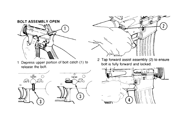
2-19. OPERATING PROCEDURES - CLEARING YOUR RIFLE (CONT).
3 To lock bolt open, pull charging handle
assembly (4) rearward, press bottom of bolt
catch (5), and allow bolt to move forward
until it engages bolt catch. Return charging
handle assembly (4) forward.
NOTE
Ensure that selector lever (1) is on
SAFE.
4 Check receiver and chamber (6) to ensure
these areas contain no ammunition.
2-34
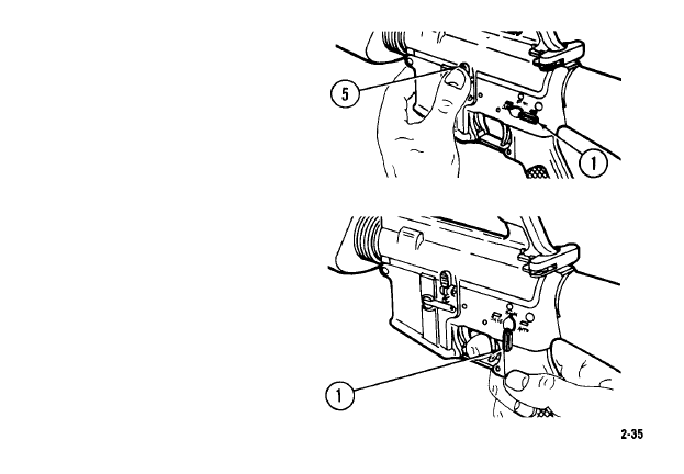
5
6
With selector lever (1) pointing toward
SAFE, allow bolt to go forward by pressing
upper portion of bolt catch (5).
NOTE
If weapon is to be stored, it should be dry
fired to release tension on hammer
spring.
Place selector lever (1) on SEMI and
squeeze trigger to release tension on
hammer spring.

2-20. OPERATION OF AUXILIARY EQUIPMENT.
CARTRIDGE DEFLECTOR - FOR “LEFTYS”
There is a cartridge deflector for left-hand shooters available from your Training Aids Service
Office (TASO).
M15A2 BLANK FIRING ATTACHMENT (BFA)
WARNING
Use only blank M200 with the BFA and do not fire directly at anyone less than 20 feet
away
CAUTION
Do not use tools to tighten attachment, HANDS ONLY
NOTE
After 50 rounds, check to see If BFA is still tight. Make sure to clean carbon buildup after each
training exercise.
1 Unscrew and slide all the
way back.
2 Hook behind first groove of
3 Slide into flash suppressor
flash suppressor.
and hand tighten.
2-37
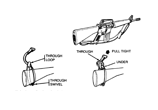
2-20. OPERATION OF AUXILIARY EQUIPMENT (CONT).
TOP SLING ADAPTER
1
Remove rifle sling from rifle.
2 Work adapter sling through swivel
and through loop.
2-38
3 Work buckle under and then through loop,
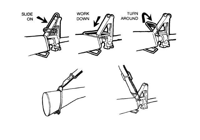
4 Attach clamp as shown.
5 Attach rifle sling to top sling adapter as shown.
2-39

Section IV. OPERATION UNDER UNUSUAL
CONDITIONS
NOTE
Unusual conditions are defined as any climatic condition requiring special mainte-
nance of the weapon.
Perform the maintenance outlined for the climate that most applies to your operational
area.
2-21. HOT, DRY CLIMATES.
NOTE
Hot, dry climates are usually dusty and sandy areas, They are hot during daylight
hours and cool during the night hours,
a. Dust and sand will get into the rifle and will cause malfunctions and excessive wear on
component working surfaces through abrasive action during the firing operations,
b. Corrosion is less likely to form on metal parts in a dry climate; therefore, lubricate internal
working surfaces only with a small amount of cleaner, lubricant and preservative (CLP) (item 1,
app D) (always shake CLP prior to use). Do not lubricate external parts of the rifle, Doing so will
only collect dust and sand, making the rifle difficult to keep clean. Do not lubricate internal
components of the magazines,

c. Using Additional Authorization List (AAL) equipment, i.e., protective cap and spare magazine
protective bags and overall rifle protective cover (item 3, app D) will help keep dust and sand from
getting into the rifle. Use these items as the tactical situation allows. As a minimum effort to keep
dust and sand out of the rifle, keep the ejection port cover closed, a cartridge magazine installed in
the rifle, and a muzzle cap on the muzzle.
NOTE
More firing, remove the protective cap and keep for later use. However, it is not
dangerous to fire the rifle with the protective cap. The cap will blow off when the first
round is fired and may be lost.
2-22. HEAVY RAIN AND FORDING.
Perform maintenance according to the appro-
priate climatic condition. Use AAL equipment and expendable items to protect the rifle, Always
keep the rifle dry. Using the protective cap will help keep water out of the barrel. Always drain any
water from the barrel before firing. Dry the bore with a swab (item 5, app D) and cleaning rod, if
necessary
2-41
2-23. EXTREMELY COLD CLIMATES.
a. To operate the rifle in extremely cold climates, depress the trigger guard plunger and open
the trigger guard. This makes it easier to operate the trigger when you are wearing arctic mittens.
(1) Apply a light coat of CLP (item 1, app D) to all functional parts,
NOTE
Always shake CLP to obtain a good mixture before applying.
(2) To prevent freezing, keep the weapon covered when moving from a warm to a cold area to
allow gradual cooling.
(3) Always keep the weapon dry.
(4) Hand function the weapon approximately every 30 minutes to help prevent freezing of
components.
(5) Do not lay a hot weapon in, snow or ice.
2-42

(6) Keep the ammunition dry. Moisture will cause malfunctions. Do not lubricate the
ammunition.
(7) Using AAL equipment, i.e., protective cap and protective bag and protective cover (item 3,
app D) will help protect your rifle. Use them whenever the tactical condition is suitable. Always
keep snow out of the barrel bore. Clean barrel bore with swab (item 5, app D) and cleaning rod, if
necessary, before firing.
2-24. HOT, WET CLIMATES.
a. Perform normal maintenance as outlined in the PMCS table (see page 2-4).
b. Perform maintenance more frequently. Inspect hidden surfaces of the bolt carrier assembly,
upper receiver and barrel assembly, and lower receiver and extension assembly for corrosion. If
corrosion is found, clean and lubricate.
c. To help prevent corrosion, remove handprints with a wiping rag (item 4, app D). Dry and
lubricate lightly with CLP (item 1, app D).
d. Check ammunition and cartridge magazines frequently for corrosion. Clean using CLP
(item 1, app D) and wipe dry with wiping rag (item 4, app D),
e. Use appropriate AAL equipment and expendable items for protection when the tactical
conditions allow.
Section V. NUCLEAR, BIOLOGICAL, AND CHEMICAL
(NBC).
General procedures can be found in FM 3-87, FM 21-40, and TM 3-220. Refer to page 3-13.

MAINTENANCE INSTRUCTIONS
Section I. LUBRICATION INSTRUCTIONS
3-1. LUBRICATION GUIDE.
a.
Cleaner, Lubricant and Preservative.
CLP (item 1, app D) is the lubricant to use on the
weapon at all temperatures.
b. Lightly
Lubricate.
A film of oil barely visible to the eye.
c.
Generously Lubricate.
Heavy enough so that it can be spread with the finger.
NOTE
These lubrication instructions are mandatory.
Section Il. TROUBLESHOOTING PROCEDURES
3-2. INTRODUCTION.
a. The table lists the common malfunctions which you may find during the operation or
maintenance of the rifle. You should perform the teats/inspections and corrective actions in the
order listed.
b. This manual cannot list all malfunctions that may occur, nor all tests or inspections and
corrective actions. If a malfunction is not listed or is not corrected by listed corrective actions, notify
organizational maintenance.
TROUBLESHOOTING
MALFUNCTION
TEST OR INSPECTION
CORRECTIVE ACTION
1. WEAPON WILL NOT FIRE.
Step 1. Check to see if selector lever (1) is in SAFE
position.
Place in SEMI or AUTO position.
Step 2. Check for improper assembly of firing pin.
Assemble correctly (p 3-43).
TROUBLESHOOTING (CONT)
MALFUNCTION
TEST OR INSPECTION
CORRECTIVE ACTION
1. WEAPON WILL NOT FIRE (CONT).
Step 3. Check for too much oil in firing pin recess (2).
Wipe off.
Step 4. Check for defective ammunition.
Remove and discard (p 4-1).
Step 5. Check for too much carbon on firing pin.
Clean (p 3-34).
3-2
TROUBLESHOOTING (CONT)
MALFUNCTION
TEST OR INSPECTION
CORRECTIVE ACTION
2. BOLT WILL NOT UNLOCK.
Step 1. Check for dirty bolt (1).
Clean (p 3-34).
Step 2.
Check for burred bolt(1).
Notify organizational maintenance.
3-3
TROUBLESHOOTING (CONT)
MALFUNCTION
TEST OR INSPECTION
CORRECTIVE ACTION
3. WEAPON WILL NOT EXTRACT.
Step 1. Check for stuck cartridge or cartridge case in chamber.
Remove stuck cartridge or cartridge case (p 2-31)
Step 2. Check for broken cartridge extractor (1) or extractor spring assembly (2)
Replace bolt assembly and notify organizational maintenance.
3-4
TROUBLESHOOTING (CONT)
MALFUNCTION
TEST OR INSPECTION
CORRECTIVE ACTION
3. WEAPON WILL NOT EXTRACT (CONT).
Step 3. Check for dirty or corroded ammunition.
a. Clean dirty ammunition with dry cloth
b. Corroded ammunition must be returned to unit supply or ammunition
Step 4.
Step 5.
personnel.
Check for carbon in chamber.
Clean (p 3-31).
Check for carbon in cartridge extractor
opening (3) on bolt assembly or cartridge
extractor lip (4).
Clean (p 3-35).
3-5

TROUBLESHOOTING (CONT)
MALFUNCTION
TEST OR INSPECTION
CORRECTIVE ACTION
4. WEAPON WILL NOT EJECT CARTRIDGE CASE.
Step 1. Check for broken ejector spring.
Report to unit armorer for repair.
Step 2. Bolt assembly is installed upside down.
The bolt cam pin is worn or the bolt cam pin hole is defective and allows for
improper assembly. Disassemble and assemble correctly. Report the defi-
ciency to unit armorer.
5. WEAPON WILL NOT FEED.
Step 1. Check for dirty or corroded ammunition.
a. Clean dirty ammunition with dry cloth.
b. Corroded ammunition must be returned to unit supply or ammunition
personnel.
Step 2. Check for dirty cartridge magazine.
Clean (p 3-26).
3-6
TROUBLESHOOTING (CONT)
MALFUNCTION
TEST OR INSPECTION
CORRECTIVE ACTION
5. WEAPON WILL NOT FEED (CONT).
Step 3. Check for defective cartridge magazine(l).
Step 4. Check for too many rounds in cartridge
magazine (1).
Remove excess rounds.
Step 5. Check for restricted buffer assembly action.
Remove (p 3-23) and clean (p 3-39).
Step 6. Cartridge magazine not fully seated.
Adjust magazine catch
(p 2-10).
3-7
TROUBLESHOOTING (CONT)
MALFUNCTION
TEST OR INSPECTION
CORRECTIVE ACTION
6. ROUND WILL NOT CHAMBER.
Step 1. Check for dirty or corroded ammunition.
a. Clean dirty ammunition with dry cloth.
b. Corroded ammunition must be returned to unit supply or ammunition
personnel.
Step 2. Check for damaged ammunition.
Replace (p 4-1).
Step 3. Check for carbon in chamber (1).
Clean (p 2-14).
3-8
TROUBLESHOOTING (CONT)
MALFUNCTION
TEST OR INSPECTION
CORRECTIVE ACTION
7. BOLT WILL NOT LOCK.
Step 1.
Step 2.
step 3.
Step 4.
Check for dirt, corrosion, or carbon buildup in
barrel locking lugs
Clean (p 3-35).
Check for frozen cartridge extractor (1).
Remove (p 3-21) and clean (p 3-34).
Check for restricted buffer assembly action.
Remove (p 3-23) and clean (p 3-39).
Restricted movement of bolt carrier assembly.
Remove (p 3-17), clean (p 3-34), and lubricate.
NOTE
When putting bolt back in, make sure gas tube fits into bolt carrier assembly and
moves freely.
3-9
TROUBLESHOOTING (CONT)
MALFUNCTION
TEST OR INSPECTION
CORRECTIVE ACTION
8. WEAPON HAS SHORT RECOIL.
Step 1. Gaps in bolt rings (not staggered).
Stagger ring gaps (p 3-42).
Step 2. Carbon or dirt in key and carrier assembly or on outside of gas tube.
Clean (p 3-34 and 3-30).
9. BOLT FAILS TO LOCK AFTER LAST ROUND.
Step 1. Check for dirty or corroded bolt catch.
Clean (p 3-38).
Step 2. Check for faulty cartridge magazine.
10, SELECTOR LEVER BINDS.
Check for not enough lubrication on selector lever (l).
Lubricate with CLP (item 1, app D).
3-10
TROUBLESHOOTING (CONT)
MALFUNCTION
TEST OR INSPECTION
CORRECTIVE ACTION
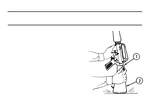
11. BOLT CARRIER ASSEMBLY ’’HUNG UP.”
Check for round jammed between bolt and
charging handle.
WARNING
Keep clear of muzzle.
a. Remove cartridge magazine.
CAUTION
After round is removed, bolt is under tension.
b. Hold charging handle assembly (1) back
and bang rifle buttstock (2) on ground.
3-11
TROUBLESHOOTING (CONT)
MALFUNCTION
TEST OR INSPECTION
CORRECTIVE ACTION
11. BOLT CARRIER ASSEMBLY ’’HUNG UP’’ (CONT)
c. While bolt is held to rear, push charging
fall through magazine well (3).
handle assembly (1) forward. Round should
3-12
TROUBLESHOOTING (CONT)
MALFUNCTION
TEST OR INSPECTION
CORRECTIVE ACTION
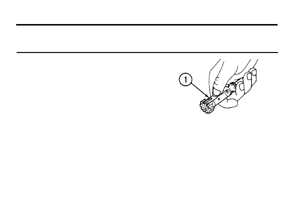
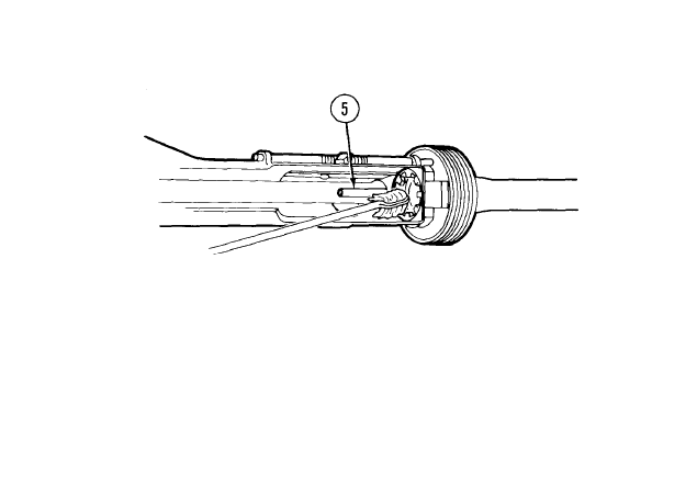
12. CAN’T SEE TRITIUM SIGHT POST.
In the event there is no illumination, notify the local Radiological
Protection Officer. Do not attempt to repair or replace the sight in
the field! if skin contact is made with any area contaminated with
tritium, immediately wash with nonabrasive soap and water.
Step 1. Luminous element broken or missing.
Turn in to unit armorer. Sights must be turned in as radioactive waste,
Step 2. Check for alinenaent of luminous elements.
Rotate front sight post up or down one click
Step 3. Luminous element dirty.
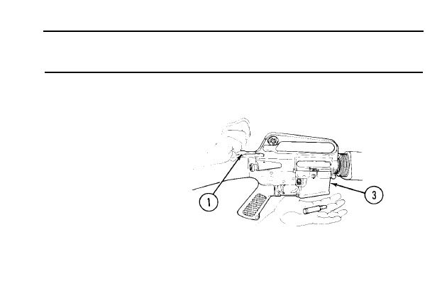
Section Ill. MAINTENANCE PROCEDURES
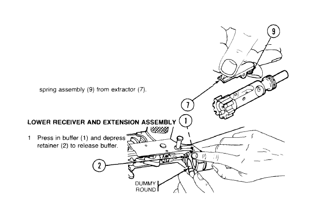
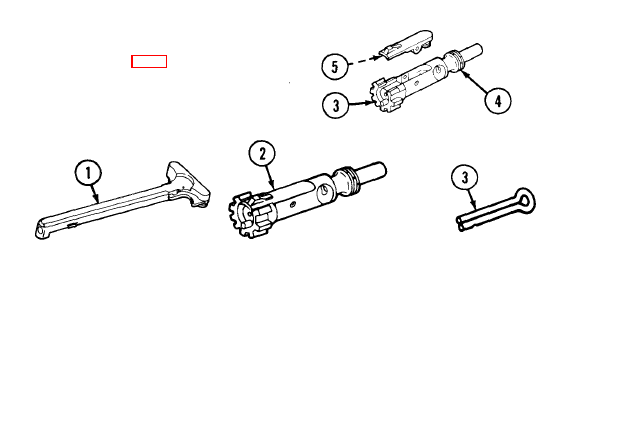
3-3. FIELD-STRIPPING M16/M16A1
CLEARING RIFLE
WARNING
To avoid accidental firing, be sure rifle is ,
clear (p 2-33).
Pull back charging handle (1) and check
chamber (2). Place selector lever on SAFE.
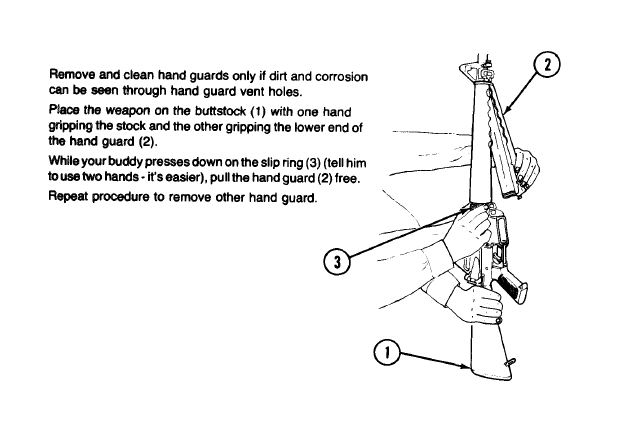
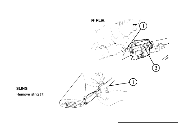
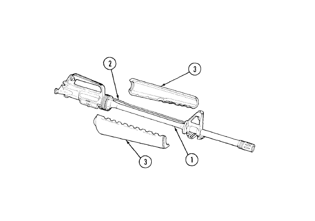
HAND GUARDS - THE “BUDDY SYSTEM”
1
2
3
4
3-15
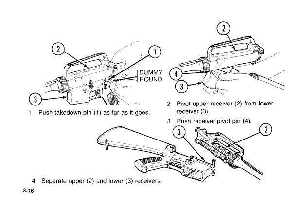
3-3. FIELD-STRIPPING M16/M16A1 RIFLE (CONT).
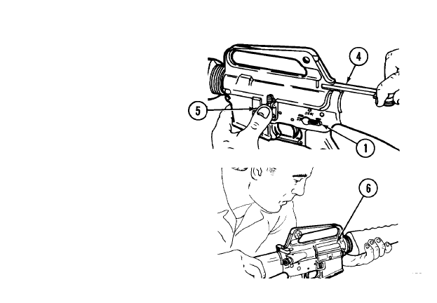
UPPER AND LOWER RECEIVERS
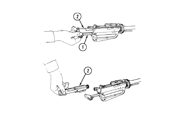
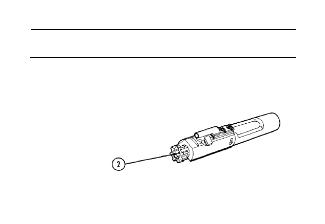
CHARGING HANDLE ASSEMBLY AND BOLT CARRIER ASSEMBLY
1 Pull back charging handle assembly (1) and bolt carrier assembly (2).
2 Remove bolt carrier assembly(2)
3-17
3-3. FIELD-STRIPPING M16/M16A1 RIFLE (CONT).
CHARGING HANDLE ASSEMBLY AND BOLT CARRIER ASSEMBLY (CONT)
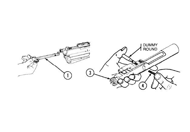
3 Pull charging handle assembly (1) back
4 Move bolt assembly (3) forward to
and down and remove it.
unlocked position and remove firing pin
retaining pin (4). Do not open or close split
end of firing pin retaining pin (4).
3-18
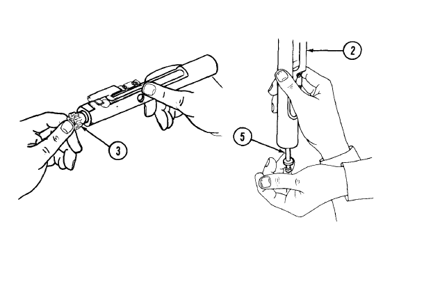
5 Push in on bolt assembly (3) to put in
6 Catch firing pin (5) as it drops out of rear of
locked position.
bolt carrier assembly (2).
3-19
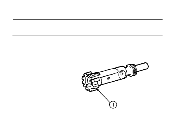
3-3. FIELD-STRIPPING M16/M16A1 RIFLE (CONT).
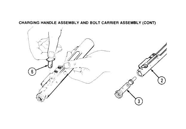
7 Give bolt cam pin(6) a 1/4 turn and lift out.
8 Remove bolt assembly (3) from bolt carrier
assembly (2).
3-20
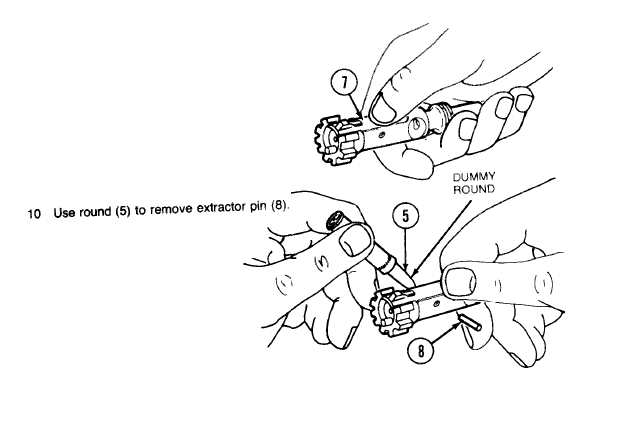
NOTE
Disassemble extractor and spring assem-
bly only when dirty or damaged.
9 Press top of extractor (7) to check that spring
works.
3-21
3-3. FIELD-STRIPPING M16/M16A1 RIFLE (CONT).
CHARGING HANDLE ASSEMBLY AND BOLT CARRIER
ASSEMBLY (CONT)
CAUTION
Do not separate insert from spring assembly (9).
11 Remove extractor (7) and spring assembly (9). Do not remove
.
3-22
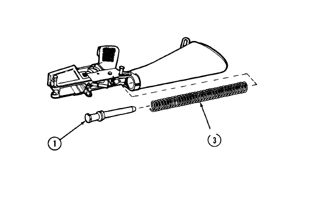
2 Remove buffer (1) and spring (3).
CAUTION
No further disassembly is allowed.
3-23
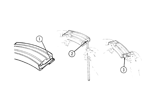
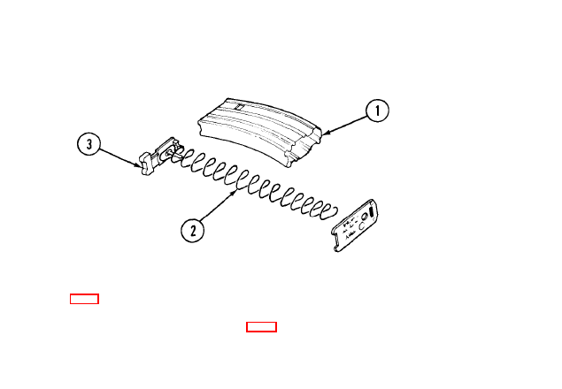
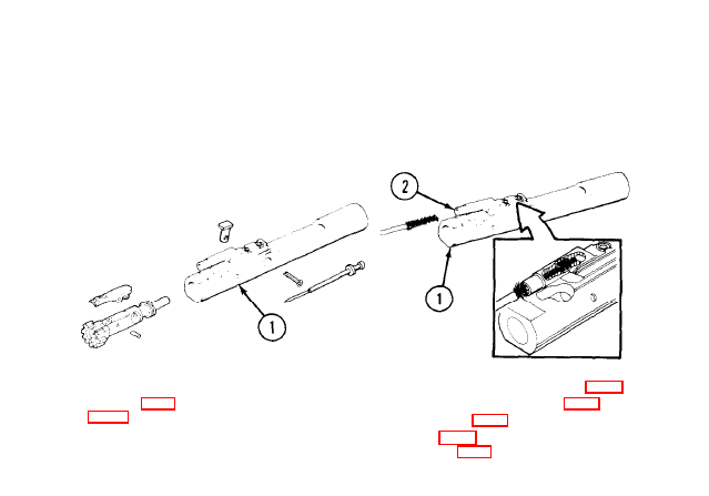
3-4. FIELD-STRIPPING CARTRIDGE MAGAZINE.
NOTE
Disassemble only if cartridge magazine is
1 Inspect feeder lips (1) for
wear or damage. If worn or
2 Use cleaning rod section to
damaged, replace
pry up, push out, and
magazine.
release base catch (2).
3-24
dirty
3 Slide base (3) from car-
tridge magazine,
4 Jiggle spring(4) and follower to remove.
3-25
3-5. MAINTENANCE OF CARTRIDGE MAGAZINE.
CLEANING, INSPECTION, AND REASSEMBLY
1 Clean and lubricate, Use swab (item 5, 2
app D) to wipe dirt from tube (1 ), spring (2),
and follower (3). Lightly lubricate spring (2)
and follower (3) with CLP (item 1, app D).
Inspect spring (2) and follower (3) for dam-
age. If parts are damaged, replace car-
tridge magazine.
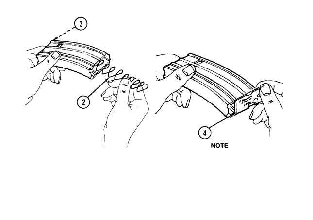
3 Jiggle spring (2) and follower (3) to install.
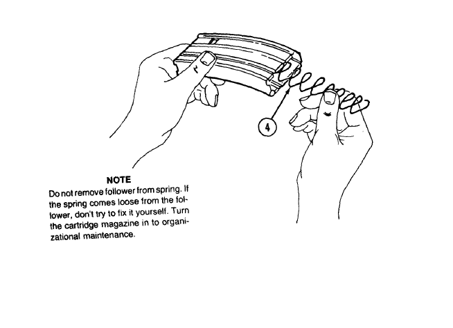
If spring comes loose from follower,
turn in the pieces. Don’t try to fix it
yourself.
4 Make sure printing is on the outside of the
base. Slide base (4) under all four tabs.
3-27
3-6. MAINTENANCE
CLEANING
OF UPPER RECEIVER AND BARREL ASSEMBLY.
NOTE
Don’t reverse direction of bore brush while it’s in bore.
Use CLP (item 1,app D) on the following areas:
a. All areas of powder fouling, corrosion, dirt and rust
b. Bore and chamber.
c. Upper receiver and barrel assembly Iocking lugs.
d. Gas tube.
Use cleaning rod, bore brush, and CLP (item 1, app D). Run rod (1) through chamber (2) and
flash suppressor (3).
Install chamber brush on cleaning rod (1), dip in CLP (item 1, app D), and insert in chamber (2)
and locking lugs (4). Clean by pushing and twisting cleaning rod.
3-29
3-6. MAINTENANCE
ASSEMBLY (CONT).
CLEANING (CONT)
OF UPPER RECEIVER AND BARREL
NOTE
Gas tubes will discolor from heat. Do not attempt to remove discoloration.
Use a wornout bore brush to perform the following step. This procedure ruins the
bore brush.
3 Use a bore brush to clean outside surface of protruding gas tube (5) (get sides and bottom from
bottom of upper receiver).
3-30
4
5
6
To remove carbon, let CLP (item 1, app D) set. Then wipe off clean. A bore brush may be used
with care to loosen heavy buildup of carbon.
Wipe dry by running rod (1) with swab holder with clean swabs (item 5, app D) through
chamber (2) and flash suppressor (3).
3-31
3-6. MAINTENANCE OF UPPER RECEIVER AND BARREL
ASSEMBLY (CONT).
INSPECTION
Inspect barrel (l), gas tube (2), and hand guards (3) for cracks, bends, or breaks. If you think apart
is bad, notify organizational maintenance.
3-32
LUBRICATION
1 Lightly lubricate bore and chamber, outer surface of barrel and front sight, and surfaces under
hand guards.
2 Start at receiver (1) and go right through the flash suppressor (2). Don’t reverse directions
3 Lubricate locking lugs (3).
to work CLP (item 1, app D) into the spring
using a round (5).
3-33
3-7. MAINTENANCE OF CHARGING HANDLE ASSEMBLY AND BOLT
CARRIER ASSEMBLY.
CLEANING
CAUTION
Do not use firing pin to clean inner surfaces of bolt or bolt carrier assembly,
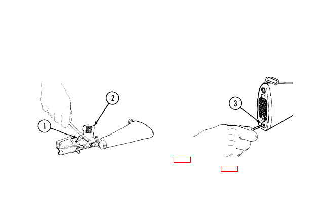
1 Clean all parts and outer surfaces of the
2 Clean the bolt carrier key (2) with a worn
bolt carrier assembly (1) with a swab
bore brush dipped in CLP (item 1, app D).
(item 5, app D) saturated with CLP (item 1,
Dry with a pipe cleaner(item 2, app D) and
swab (Item 5, app D). Use a pipe cleaner
3-34
(item 2, app D) to apply a light coating of
CLP (item 1, app D) to carrier key (2).
3 Remove carbon deposits and dirt from
locking lugs (3) with bore brush dipped in
CLP (item 1, app D),
4 Clean areas behind bolt rings (4) and under
lip of extractor (5),
INSPECTION
1 Inspect charging handle
assembly (1) for cracks,
bends, or breaks.
2
WARNING
DO NOT interchange bolt
assemblies between rifles.
Inspect bolt assembly (2) for
3 Inspect firing pin
retaining pin (3) for
bends, breaks, or
dents.
cracks or fractures, especially
in the cam pin hole area.
3-35
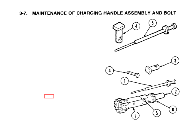
CARRIER ASSEMBLY (CONT).
INSPECTION (CONT)
4 Inspect bolt cam pin (4) for cracks or chips.
5 lnspect firing pin (5) for bends, cracks, or blunted tip.
LUBRICATION
1 Lightly lubricate firing pin(l) and firing pin
recess (2) in bolt assembly.
2 Generously lubricate outside of bolt cam
pin (3) and firing pin retaining pin (4) with
CLP (item 1, app D). Make certain to lubri-
cate bolt assembly cam pin hole (5), bolt
rings (6), and outside of the bolt
assembly (7).
3-36
4 Lightly lubricate with CLP (item 1, app D)
inner and outer surfaces of bolt carrier
assembly (8). Generously lubricate
slide (9) and cam pin area (1 O) of bolt car-
3
Dry inside key of bolt carrier assembly (8).
Place one drop of CLP (item 1, app D)
5 Lightly lubricate charging handle
inside key.
assembly (1 1).
3-37
3-8. MAINTENANCE OF LOWER RECEIVER AND EXTENSION
ASSEMBLY.
CLEANING
CAUTION
Do not use steel/wire brush or any type of abrasive material to clean aluminum
surfaces.
1 Wipe dirt from trigger (1) with a swab (item 5, app D).
3
Use pipe cleaner (item 2,
and cleaning brush to clean powder fouling, corrosion, and
screw drain hole (3),
dirt from outside parts of lower receiver and extension
assembly (2)
4 Clean buffer
inside lower
assembly (2)
dipped in CL
INSPECTION
1 Examine lower receiver and extension as-
sembly (1) for broken or bent trigger (2),
buttstock (3), corroded or deformed lower
receiver (1), cracked or damaged rifle grip
(4), and bent or damaged selector lever(5).
Look at inside parts of lower receiver and
extension assembly (1) for cracks, dents,
or breaks.
2 If you think the parts are bad, notify organi-
zational maintenance.
3-39
3-8. MAINTENANCE OF LOWER RECEIVER AND EXTENSION
ASSEMBLY (CONT).
LUBRICATION
1 Lightly lubricate inside of lower
receiver and extension
assembly (1), spring (2), and
buffer assembly (3) with CLP
(item 1, app D).
2
Generously lubricate
takedown (4) and pivot pins (5)
and inside parts of lower receiver
and extension assembly (1) with
CLP (item 1, app D),
3-40
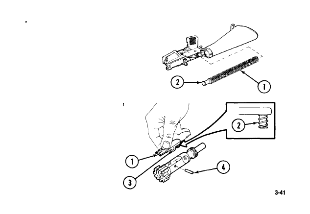
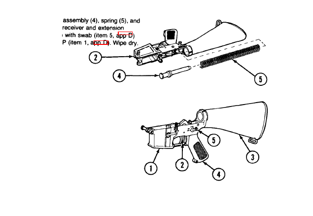
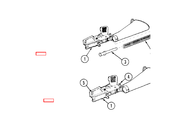
REASSEMBLY OF M16/M16A1 RIFLE.
LOWER RECEIVER AND EXTENSION ASSEMBLY
Insert spring (1) and buffer (2).
BOLT CARRIER ASSEMBLY AND
CHARGING HANDLE ASSEMBLY
1
2
3
NOTE
New extractor has silicone insert with
spring. Be sure not to lose it.
If the spring comes loose, seat the
large end of spring in the extractor,
Insert extractor (1) and spring
assembly (2) into bolt.
Push extractor (1) and spring
assembly (2) down. Aline hole (3)
with hole in bolt and insert extractor
pin (4).
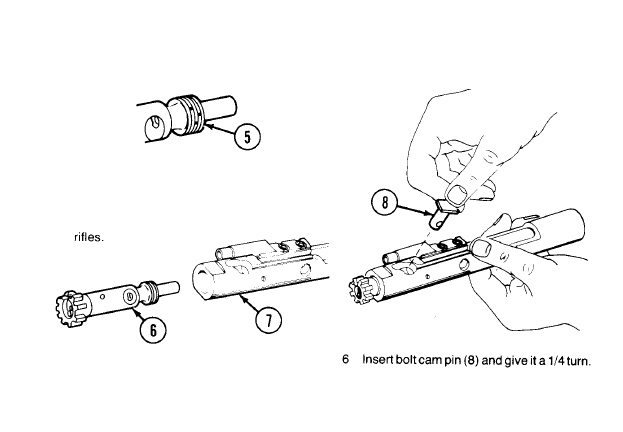
3-9. REASSEMBLY OF M16/M16A1 RIFLE (CONT).
BOLT CARRIER ASSEMBLY AND CHARGING HANDLE ASSEMBLY (CONT)
4 Stagger gaps in bolt rings (5) to stop gas
loss.
WARNING
Don’t switch bolt assemblies between
5 Slide bolt assembly (6) into bolt carrier
assembly (7).
3-42
7 Drop firing pin (9) in
opening and seat.
8 Pull boltassembly (6) back and replace firing pin retaining
pin (10).
NOTE
Firing pin should not fall out when bolt carrier assem-
bly is turned upside down.
3-43
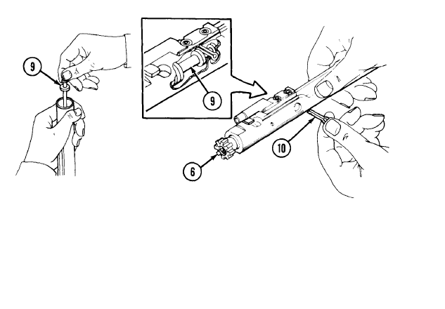
3-9. REASSEMBLY OF M16/M16A1 RIFLE (CONT).
BOLT CARRIER ASSEMBLY AND CHARGING HANDLE ASSEMBLY (CONT)
9 Turn bolt carrier assembly (7)
10 Engage, then push, charging handle
over and try to shake out
assembly (11) part way into upper receiver.
firing pin.
3-44
11
12
NOTE
Be sure bolt assembly is extended from bolt carrier.
Push charging handle assembly (11) and bolt carrier assembly (7) together into upper
receiver (12).
3-45
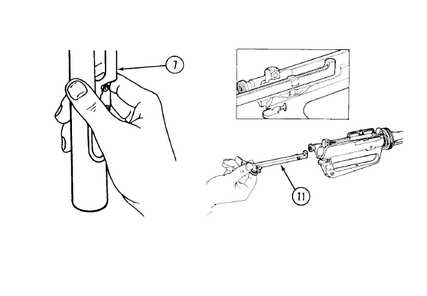
3-9. REASSEMBLY OF M16/M16A1 RIFLE (CONT).
JOINING UPPER AND LOWER RECEIVERS
1 Join upper receiver (1) and lower
2 Aline the pivot pin holes and push
receiver (2).
pivot pin (3) in.
3-46
3
4
5
CAUTION
Selector lever must be on SAFE or SEMI before
closing upper receiver.
Place selector lever (4) on SAFE or SEMI
before closing upper receiver.
CAUTION
Ejection port cover must be
closed before closing upper
and lower receiver to prevent
damage to cover.
Close ejection port cover (5).
Close upper receiver (1) and lower
receiver (2). Push in takedown
pin (6).
3-47
3-9. REASSEMBLY OF M16/M16A1 RIFLE (CONT)
HAND GUARDS - THE “BUDDY SYSTEM”
1
2
3
4
Place the weapon on the buttstock (1) with one hand
gripping the stock and the other gripping the lower end of
the barrel. Insert hand guard into hand guard cap (2).
Have your buddy press down on slip ring (3).
Install hand guard (4).
Repeat these steps to install other hand guard.
3-48
3-10. FUNCTIONAL CHECK.
WARNING
To avoid accidental firing, be sure cartridge
magazine is removed and chamber is clear
(p 2-34).
3-10. FUNCTIONAL CHECK (CONT).
2
Place selector lever (2) on SEMI. Squeeze
trigger (3); hammer should fall. Hold trigger
to the rear. Pull charging handle
assembly (1) to rear and release. Release
trigger (3). You should hear a click as you
release the trigger. Squeeze again; ham-
mer should fall.
3 Place selector lever (2) on AUTO. Pull
charging handle assembly (1) to rear and
release, Squeeze the trigger; hammer
should fall. Hold trigger to the rear and cock
the rifle. Release the pressure on the trig-
ger and squeeze it to the rear again. The
hammer should not fall because it should
have fallen when the bolt was allowed to
move forward during the cocking
sequence.
3-50
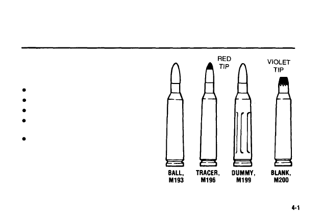
AMMUNITION
AUTHORIZED AMMUNITION.
W A R N I N G
To avoid possible explosion, do not fire:
Seriously corroded ammunition
Dented cartridges
Cartridges with loose bullets
Cartridges exposed to extreme heat 135°F
(57°C) until they have cooled
Blank ammunition toward personnel within 20
feet or less from the muzzle, because frag-
ments of a closure wad or particles of unburnt
propellant might inflict injury within that range.
a. Use only authorized ammunition that is
manufacture to US specs.
b. Keep dry and clean. Your life depends
on it!

REFERENCES
A-1. SCOPE.
This appendix lists techmical manuals referenced in this manual.
A-2. DEPARTMENT OF ARMY PAMPHLETS (DA PAM).
The Army Maintenance Management System (TAMMS) DA PAM 738-750
A-3. FIELD MANUALS (FM).
Nuclear, Biological and Chemical (NBC) Reconnaissance
and Decontamination Operations . . . .. . . . . .. . .. . . FM 3-87
First Aid for Soldiers . . . . . . .. . .. . . . . . . . . . . . . . . . .. . . .. . . .. . . . .. . . . . .. FM 21-11
NBC (Nuclear, Biological and Chemical) Defense . . .. . . . . .... FM 21-40
M16A1 Rifle and Rifle Marksmanship . . . . . .. . . . . . . . ..FM 23-9
A-4. TECHNICAL MANUALS (TM).
Chemical, Biological and Radogical (CBR)
Decontamination .. . . . . . .. . .. . . . . . .. . . . .. TM 3-220

COMPONENTS OF END ITEM AND BASIC ISSUE
ITEMS LISTS
Section I. INTRODUCTION
B-1. SCOPE. This appendix lists components of end item and basic issue items for the rifle
to help you inventory items required for safe and efficient operation.
B-2. GENERAL.
The Components of End Item and Basic Issue Items Lists are divided
into the following sections:
a. Section //. Components of End Item. This listing is for informational purposes only, and is
not authority to requisition replacements. These items are part of the end item, but are removed
and separately packaged for transportation or shipment. As part of the end item, these items must
be with the end item whenever it is issued or transferred between property accounts. Illustrations
are furnished to assist you in identifying the items.
b. SectIon Ill. Basic Issue Items. These are the minimum essential items required to place the
rifle in operation, to operate it, and to perform emergency repairs. Although shipped separately
packaged, BII must be with the rifle during operation and whenever it is transferred between
property accounts. The illustrations will assist you with hard-to-identify items. This manual is your
authority to request/requisition replacement Bll, based on TOE/MTOE authorization of the end
item.

B-3. EXPLANATION OF COLUMNS.
The following provides an explanation of col-
umns found in the tabular listings:
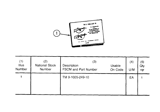
a. Column (1) - IIIustration Number (IIIus Number). This column indicates the number of the
illustration in which the item is shown.
b. Column (2) - National Stock Number. Indicates the National stock number assigned to the
item and will be used for requisitioning purposes.
c. Column (3) - Description. Indicates the Federal item name and, if required, a minimum
description to identify and locate the item. The last line for each item indicates the FSCM (in
parentheses) followed by the part number.
d. Column (4) - Unit of Measure (U/M). Indicates the measure used in performing the actual
operational/maintenance function. This measure is expressed by a two-character alphabetical
abbreviation (e.g., ea, in., pr).
e. Column (5) - Quantify required (Qty rqr). Indicates the quantity of the item authorized to be
used with/on the equipment.
B-2
Section Il. COMPONENTS OF END ITEM
B-3
Section Ill. BASIC ISSUE ITEMS
B-4

ADDITIONAL AUTHORIZATION LIST (AAL)
Section 1. INTRODUCTION
C-l. SCOPE.
This appendix lists additional items you are authorized for the support of the
rifle.
C-2. GENERAL. This list
identifies items that do not have to accompany the rifle and that do
not have to be turned in with it. These items are all authorized to you by CTA, MTOE, TDA, or JTA.
C-3. EXPLANATION OF LISTING.
National stock numbers, descriptions, and quan-
tities are provided to help you identify and request the additional items you require to support this
equipment. The items are listed in alphabetical sequence by item name under the type document
(i.e., CTA, MTOE, TDA, or JTA) which authorizes the item(s) to you.

Section Il. ADDITIONAL AUTHORIZATION LIST (AAL)
(1)
NATIONAL
STOCK
NUMBER
1005-00-193-8306
1005-00-118-6192
1005-00-903-1296
1005-00-999-1435
C-2
(2)
DESCRIPTION
USABLE
FSCM AND PART NUMBER
ON CODE
CTA AUTHORIZED ITEMS
BAG, PROTECTIVE: for 30
round magazine (500 per bx)
required 1 per magazine
(1 9204) 8448464
BLANK FIRING ATTACHMENT, M15A2:
(For training only)
(1 9204) 12002900
BRUSH, CLEANING, SMALL ARMS: bore
(1 9204) 11686340
BRUSH, CLEANING, SMALL ARMS: chamber
(1 9204) 8432358
(3)
U/M
EA
EA
EA
EA
(4)
QTY
AUTH
1
1
1
1

Section Il. ADDITIONAL AUTHORIZATION LIST
(AAL) (CONT)
(1)
NATIONAL
STOCK
NUMBER
1005-00-494-6602
5340-00-880-7666
1005-01-171-4778
8465-00-781-9564
(2)
DESCRIPTION
USABLE
FSCM AND PART NUMBER
ON CODE
BRUSH, CLEANING, SMALL ARMS: tooth
(19204) 8448462
CAP, PROTECTIVE, DUST
[19204) 8445067
CARTRIDGE CASE DEFLECTOR
ASSEMBLY
(19200) 9378328
CASE, MAINTENANCE EQUIPMENT: for
rifles without buttstock stowage
(81349) MIL-C-43737
or
CASE, SMALL ARMS: for rifles
with buttstock stowage
(19204) 8448751
(3)
U/M
EA
EA
EA
EA
(4)
QTY
AUTH
1
1
1
1
1
C-3

Section Il. ADDITIONAL AUTHORIZATION LIST
(AAL) (CONT)
NATIONAL
STOCK
NUMBER
1005-01-113-0321
1005-00 -406-1570
1005-00-921-5004
(2)
DESCRIPTION
USABLE
FSCM AND PART NUMBER
ON CODE
HANDLE SECTION, CLEANING ROD, SMALL
ARMS
(1 9204) 8436776
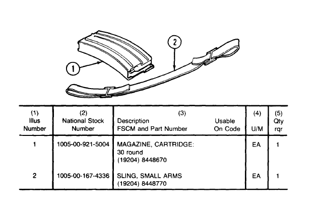
KIT, ADAPTER SLING
(1 9204) 8448471
MAGAZINE, CARTRIDGE: 30 round
(1 9204) 8448670
U/M
EA
EA
EA
(4)
QTY
AUTH
1
1
6
C-4

Section Il. ADDITIONAL AUTHORIZATION LIST
(AAL) (CONT)
(1)
(2)
(3)
(4)
NATIONAL
DESCRIPTION
STOCK
USABLE
QTY
NUMBER
FSCM AND PART NUMBER
ON CODE
U/M
AUTH
1005-00-233-9031
1005-00-050-6357
1005-00-937-2250
PLATE, LOCKING: for riot control use,
prevents selector from automatic fire
(refer to organizational maintenance
for installation and instructions on use)
(19204) 8448676
ROD SECTION, CLEANING ROD, SMALL ARMS
(19204) 8436775
SWAB HOLDER SECTION, CLEANING ROD,
SMALL ARMS
(19204) 11686327
EA
EA
EA
1
3
1

Section Il. ADDITIONAL AUTHORIZATION LIST
(AAL) (CONT)
(1)
NATIONAL
STOCK
NUMBER
1005-00-017-9701
1005-00-890-2609
1005-00-406-1570
(2)
DESCRIPTION
USABLE
FSCM AND PART NUMBER
ON CODE
MTOE AUTHORIZED ITEMS
BAYONET - KNIFE M7 W/SCABBARD
(1 9204) 8427025
BIPOD, RIFLE M3 W/CARRYING CASE
(1 9204) 8445081
TOP SLING ADAPTER KIT
(1 9204) 8448471
(3)
U/M
EA
EA
EA
(4)
QTY
AUTH
1
1
1
C-6

EXPENDABLE/DURABLE SUPPLIES AND
MATERIALS LIST (EDSML)
Section I. INTRODUCTION
D-1. SCOPE.
This appendix lists expendable supplies and materials you will need to
operate and maintain the M16/M16A1 rifle. This listing is for informational purposes only and is not
authority to requisition the listed items. These items are authorized to you by CTA 50-970,
Expendable/Durable Items (Except Medical, Class V, Repair Park, and Heraldic Items), or CTA
8-100, Army Medical Department Expendable/Durable Items.
D-2. EXPLANATION OF COLUMNS.
a. Column (1) - Iterm Number. This number is assigned to the entry in the listing and is
referenced in the narrative instructions to identify the material (e.g., “Use protective cover (item 3,
app D)”).

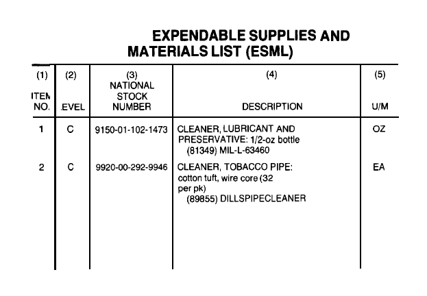
D-2. EXPLANATION OF COLUMNS (CONT).
b. Column (2) - Level. This column identifies the lowest level of maintenance that requires the
listed item.
C - Operator/Crew
c. Column (3) - National Stock Number. This is the National stock number assigned to the
item; use it to request or requisition the item.
d. Column (4) - Description. Indicates the Federal item name and, if required, a description to
identify the item. The last line for each item indicates the Federal Supply Code for Manufacturer
(FSCM) in parentheses followed by the part number.
e. Column (5) - Unit of Measure (U/M). Indicates the measure used in performing the actual
maintenance function. This measure is expressed by a two-character alphabetical abbreviation
(e.g., ea, in., pr). If the unit of measure differs from the unit of issue, requisition the lowest unit of
issue that will satisfy your requirements.
D-2
Section Il.
D-3

EXPENDABLE SUPPLIES AND MATERIALS LIST (ESML) (CONT)
(1)
(2)
ITEM
NO.
LEVEL
3
c
4
c
5
c
D-4
(3)
NATIONAL
STOCK
NUMBER
1005-00-809-2190
7920-00-205-1711
1005-00-912-4248
(4)
DESCRIPTION
COVER, PROTECTIVE
(1 9204) 8448213
RAG, WIPING: 50 lb bdl
(58536) A-A-531
SWAB, SMALL ARMS CLEANING:
cotton 1 pkg (1000 per package)
(1 9204) 11686408
(5)
U/M
EA
LB
EA

STOWAGE GUIDE
Section I. INTRODUCTION
E-1. SCOPE.
This appendix shall be included only when specified by the procuring activity.
E-2. GENERAL.
This guide shall detail the physical installation/stowage location of all
applicable AAL and expendable supply items required to be carried with the equipment.
Section II. GUIDE FOR STOWING ACCESSORIES IN
SMALL ARMS ACCESSORIES CASE OR IN BUTTSTOCK
NOTE
The diagram is just a guide. It is not mandatory to assemble the contents according to
the diagram.
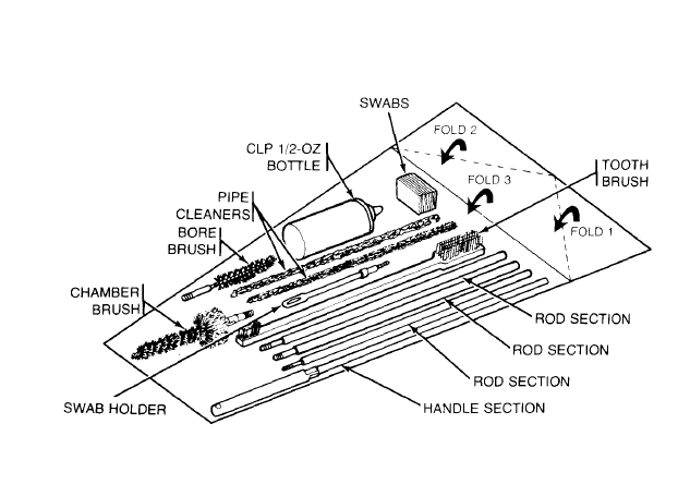
MAINTENANCE EQUIPMENT CASE: SMALL ARMS ACCESSORIES, PACKED WITH
CLEANING EQUIPMENT AND SUPPLIES
E-2
NOTE
See illustration below on how to open buttstock on rifles with buttstock storage.
E-3

Page
A
Additional Authorization List . . . . . . . . . . . .. . . . . . .. . . . .. . . . . . . . . .. .. . . C-1
Ammunition . . . . .. .. . . . . . . . .. . .. . . . . . . . .. . . . . . 4-1
Assembly and Preparation for Firing- Clean and Lube . .. . . . . . . . . . . . . . . . . . . . . .. . . . . . . . . . . 2-14
Authorized Ammunition . . . . . . . . . . . . . . . . . . . . . . . . . . . . . . . ...4-1
C
D
E
Equipment Characteristics, Capabilities, and Features 1-3
Equipment Data . . . .. . . . . .. . . .. . . . . .. . . . . .. . . .. . . . . . . . . .1-4
Equipment Description . . . . . . . . . . . . . . . . . . . . . . . . . ...1-3
Expendable/Durable Supplies and Materials List D-1
F
Field Stripping . . . . . . . . . . . . . . . . . . . .. . . .. . . . . .. . . . . . . . . . . ...3-14
Functional Check . . . . . . . . . . . . .. . .; . .. . . . .. . . . . . . . . . . . . ...3-49

Page
G
I
L
M
Maintenance Forms and Records . . . . . . . . . . . . . ...1-1
Maintenance of Cartridge Magazine. . . . . . . . . . . . . . . . . . . . . . . . . . . . . . . . . . . ...3-26
Maintenance of Charging Handle Assembly and Bolt Carrier Assembly .. 3-34
Maintenance of Lower Receiver and Extension Assembly . . . . . . . . . . . . . . . . . ...3-38
Maintenance of Upper Receiver and Barrel Assembly . . . . . . . . . . . . . . . . .3-28
Maintenance Procedures . . . . . . . . . . . . . . . . . . . . . . . . . . . . . . . . . . . . . . . . . . . . . . . . . . . . . ...3-14
Index 1

O
Operating Procedure . . . . . . . . . . . . .... . . . . . .. . . . . . . .. . .. . .. . . . . . ...2-24
Operation of Auxiliary Equipment . . . . . .. . .. . . .. . . . . . . . . . . . . . ...2-36
Operation Under Unusual Conditions . . . . . . . . . . . . . . . . . . ...2-40
Operation Under Usual Conditions.. . . . .. . . . .. .. . .. . .. .. . . ... . ...2-13
Operator Preventive Maintenance Checks and Services . . . . . . . .. . . . . .. . .. 2-5
Preventive Maintenance Checks and Services (PMCS) . . . . . . . . ...2-4
R
Reassembly of M16/M16A1 Rifle . . . . . . . . . . . . . . . . . . . . . . . . . . . . . . . . . . . . . . . . . . . . ...3-41
References . . . . .. . . . . . . .. . . . . .. . . . . .. . . . . .. . . . . . .. . . . . . .. . . .. . . . .. . . . .. A-0
Reporting Equipment Improvement Recommendations (EIR’s) . . . . . . . . .. .. . .. . . . ...1-2
s
Scope . . . . . . .. .. .. . . .. .. . . . . . . . . . . .. . . . . . . . .. . . .. . . . .. . . . . . . .. . . . . . . . .. . . . ...1-1
Stowage Guide . . . . . . . . . . . . . . . . . . . . . . . . . . . . . .. . . . . . . .. . .. .. . . . .. . . . .. E-1
T
Technical Principles of Operation . . . . .. .. . .. .. . . . .. . . . . . . . . . . . . . . . . . . . ...1-5
Troubleshooting . . . . . . . . . . . . . . . . . . . . . . .. . . .. . . . . . . . . . . ...3-1
Index 2

BY order of the Secretary of the Army:
JOHN A. WICKHAM, JR.
General, United States Amy
official:
Chief of Staff
DONALD J. DELANDRO
Brigadier General, united States Amy
The Adjutant General
Distribution:
TO
be distributed in accordance with DA Form 12-40,
Operator and Crew Maintenance requirements for Rifle,
5.56MM, M16, M16A1.


Document Outline
- TABLE OF CONTENTS
- LAST CHANGE
- WARNINGS
- CHAPTER 1
- CHAPTER 2
- CHAPTER 3
- CHAPTER 4
- APPENDIX
- INDEX
- PAGES
- PAGE 1-1
- PAGE 1-2
- PAGE 1-3
- PAGE 1-4
- PAGE 1-5
- PAGE 2-1
- PAGE 2-4
- PAGE 2-5
- PAGE 2-13
- PAGE 2-14
- PAGE 2-16
- PAGE 2-20
- PAGE 2-21
- PAGE 2-24
- PAGE 2-33
- PAGE 2-36
- PAGE 2-40
- PAGE 2-43
- PAGE 3-0
- PAGE 3-1
- PAGE 3-13
- PAGE 3-14
- PAGE 3-26
- PAGE 3-28
- PAGE 3-34
- PAGE 3-38
- PAGE 3-41
- PAGE 3-49
- PAGE 4-1
- PAGE A-0
- PAGE B-1
- PAGE C-1
- PAGE D-1
- PAGE E-1
- PAGE INDEX 0
Wyszukiwarka
Podobne podstrony:
Instrukcja do PDF Splitter And Merger
Instrukcja do ćw 10 Uruchomienie przemiennika częstotliwości z poziomu pulpitu operatorskiego
Heathkit AA 151 Stereo Amplifier Assembly and Operation manual
Instrukcja do ćw 10 Uruchomienie przemiennika częstotliwości z poziomu pulpitu operatorskiego
Heathkit AA 151 Stereo Amplifier Assembly and Operation manual
Instrukcja do zad proj 13 Uklad sterowania schodow ruchom
MSIB Instrukcja do Cw Lab krystalizacja
Instrukcja do MHDD
Instrukcja do cwiczenia 1
Instrukcja do programu WSPR
Instrukcja do ćw 18 Montaż i demontaż magazynu składowania MPS
Instrukcja do VirtualPneumoLab2
Instrukcje do ćwiczeń 2013
Instrukcja do ćw 06 Sterowanie pracą silnika indukcyjnego za pomocą falownika
Upow.do wylozenia projektu operatu 31 03 03, studia, rok II, EGiB, od Pawła
więcej podobnych podstron