
IEEE 802.11 Wireless LAN Security Performance
Using Multiple Clients
Honours Project Report, 2003
Nilufar Baghaei
nab49@student.canterbury.ac.nz
Department of Computer Science and Software Engineering
University of Canterbury, Christchurch, New Zealand
Supervisor: Assoc. Prof. Ray Hunt

2
Abstract
IEEE 802.11 Wireless Networks have gained popularity, providing users mobility and
flexibility in accessing information. Existing solutions for wireless LAN networks have been
exposed to security vulnerabilities. Previous study has evaluated the security performance of
IEEE 802.11 wireless networks using single server-client architecture. This research
investigated the effect of multiple security mechanisms on the performance of multi-client
congested and un-congested networks. The effect of different TCP and UDP packet sizes on
performance of secure networks was also studied. The results showed that WEP encryption
significantly degrades the performance of congested wireless networks. Network performance
degradation increased as the number of clients was increased under all security mechanisms.
Acknowledgements
I would like to thank my supervisor, Associate Professor Ray Hunt, for his support and guidance
throughout the year, Aun Haider for our earlier discussion on congestion, Associate Professor
Krzysztof Pawlikowski for his helpful comments and Jenne Wong for Windows operating system
directions. I also like to thank Dr. Malcolm Shore and Craig Miller for discussing the results with
me, and Lucent Technologies and MediaLab for providing the wireless equipment. Thanks also to
my family for the support they have given me, and to the 2003 fourth year students, who made this
year enjoyable.

3
Contents
1 Introduction 4
2 Background 5
2.1 Wireless
Networks ....................................................................................................... 5
2.1.1 Benefits and Limitations ................................................................................. 6
2.2 IEEE 802.11 Wireless Standards.................................................................................. 6
2.2.1 History
of
802.11............................................................................................. 6
2.2.2 Protocol
Layers................................................................................................ 8
2.2.3 Types of networks ........................................................................................... 8
2.2.4 MAC Layer ................................................................................................. 10
2.3 Bandwidth of 802.11 Wireless LANs ........................................................................ 13
2.3.1 Interference.................................................................................................... 13
2.3.2 Frequency congestion.................................................................................... 14
2.4 Wired Equivalent Privacy (WEP) .............................................................................. 15
2.4.1 WEP
Protocol................................................................................................ 15
2.4.2 Problems with WEP ...................................................................................... 16
2.4.3 WEP
Improvement ........................................................................................ 16
2.5 IEEE 802.1x Security Protocol................................................................................... 19
2.5.1 Terminology .................................................................................................. 19
2.5.2 802.1x
Architecture ....................................................................................... 20
2.5.3 802.1x in 802.11 Wireless LANs .................................................................. 20
2.5.4 EAP-TLS....................................................................................................... 21
2.6 Wireless
Performance................................................................................................. 21
3 Experimets 24
3.1 Aim............................................................................................................................. 24
3.2 Method........................................................................................................................ 24
3.2.1 Design
Considerations................................................................................... 24
3.2.2 Configuration of Wireless LAN system ........................................................ 25
3.2.3 Security
Layers.............................................................................................. 26
3.2.4 802.1x Model Implementation ...................................................................... 26
3.2.5 Traffic generator .......................................................................................... 28
3.3 Procedure.................................................................................................................... 30
3.4 Results ........................................................................................................................ 31
3.4.1 Effect of security mechanisms on performance ............................................ 31
3.4.2
Effect of adding more clients...............................................................
33
3.4.3 Effect of various packet sizes on performance.............................................. 34
3.5 Discussion .................................................................................................................. 35
3.5.1 Limitations .................................................................................................... 36
4 Future Work 37
5 Conclusions 38
Appendix A 44
Appendix B 45

4
Chapter 1
Introduction
The market for wireless communications has experienced incredible growth over recent years.
Wireless Local Area Networks (Wireless LANs) have quickly found a significant place and
popularity in business and the computer industry alike [17]. The major benefit of wireless
LANs is increased flexibility and mobility [12]. Unlike a traditional wired LAN, which
requires a wire to connect a computer to the network, users can access wireless LANs from
nearly anywhere without any restriction; that has greatly increased wireless LANs' popularity.
This significant reliance on wireless networks makes it tremendously important to maintain
reliable and secure links between the communicating parties.
Security risks in wireless networks are equal to the sum of the risk of operating a wired
network plus the new risks introduced due to the portability of wireless devices [3]. To reduce
these risks, organizations need to adopt security measures and practices that help bring down
their risks to a manageable level.
This research will investigate the performance and security issues of an IEEE 802.11 wireless
LAN with the layered security model, using multiple clients. It will study the interaction
between different security layers and their effects on performance (response time and
throughput) of congested and un-congested networks. The research will also evaluate the
effect of different TCP and UDP packet sizes on network performance, under different
security mechanisms.
Chapter 2 provides an introduction to existing wireless networks and detailed analysis of
IEEE 802.11 protocols and standards is presented. It explains the two security architectures:
WEP (an IEEE 802.11 security standard) and IEEE 802.1x authentication protocol (an
enhancement for default WEP authentication). It also discusses the prior research carried out
to evaluate the performance of wireless networks. Chapter 3 presents the goal of this research,
the design considerations and the different security mechanisms used during the experiments.
The model and system architecture is described and the experimented results are presented
and analysed. Direction for future work is presented in Chapter 4. Chapter 5 draws some
conclusion on the research presented in this report.

5
Chapter 2
Background
2.1 Wireless
Networks
Over recent years, the market for wireless communications has experienced incredible growth.
Wireless technologies have quickly found a significant place and popularity in business and
the computer industry. Their major motivation and benefit is increased flexibility and
mobility. Unlike a traditional wired network, which requires a wire to connect a computer to
the network, wireless technology enables the users to access information from anywhere
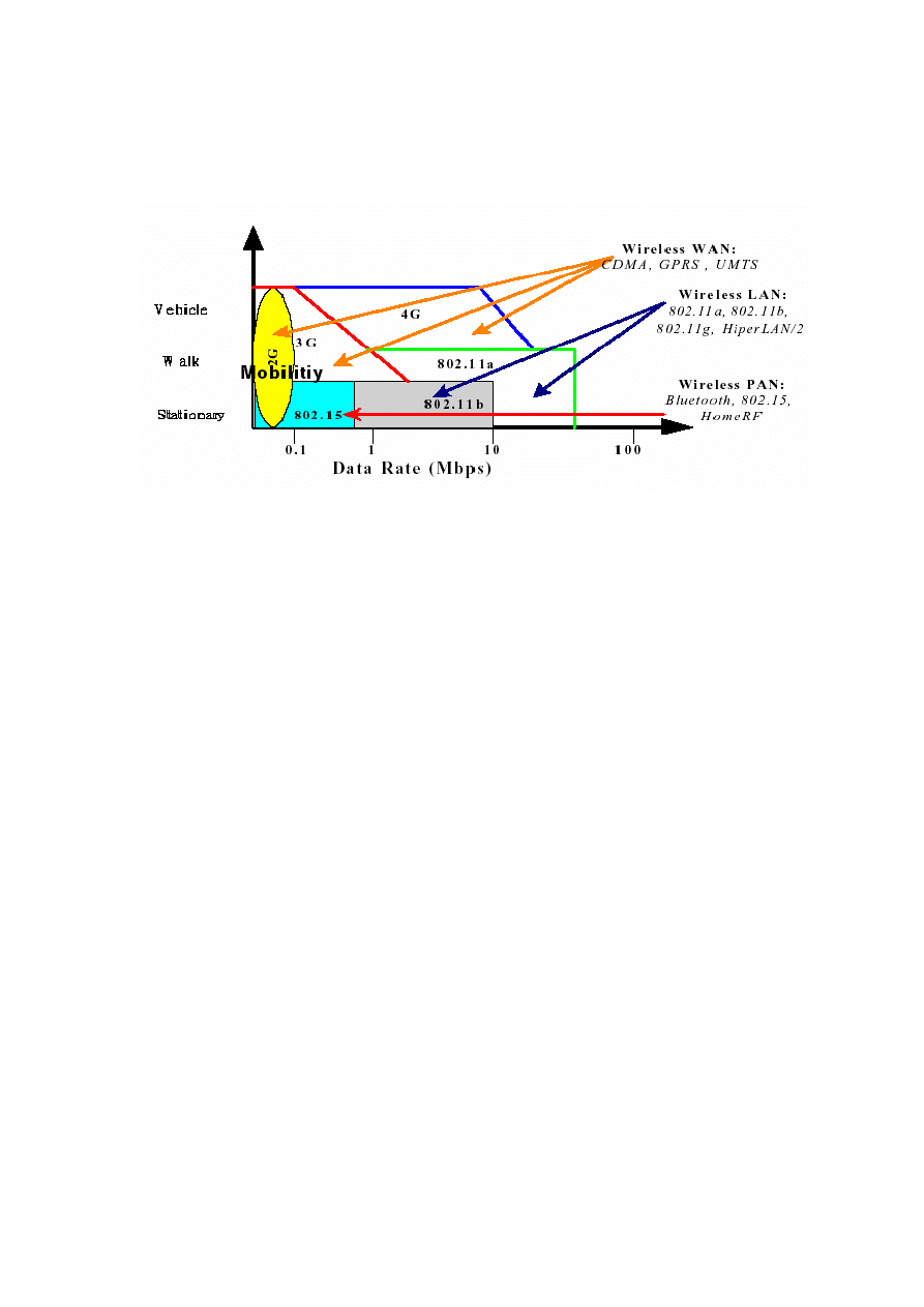
without any restriction. Wireless networks are frequently categorised into three groups based
on their coverage range [3]: Wireless Wide Area Network (WWAN), Wireless Local Area
Network (WLAN), and Wireless Personal Area Network (WPAN).
Wireless WANs include wide coverage area technologies such as Advanced Mobile Phone
Systems (AMPS), Time Division Multiple Access (TDMA), and the Code Division Multiple
Access (CDMA). Existing second-generation (2G) digital cellular systems are Global System
for Mobile (GSM) in Europe, and Personal Digital Communication (PDC) in Japan. The 2G
to 2.5G wireless WANs provides data rate from 9.6 Kbps to 348 Kbps. As for third-
generation (3G) systems, Universal Mobile Telecommunication System (UMTS) is one of the
major systems aiming for higher capacity and data rates with global mobility, and operates
around 144 Kbps to 2 Mbps [8].
Wireless LANs provide greater flexibility and portability than do traditional wired LANs.
Unlike a wired LAN, which requires a wire to access the network, a Wireless LAN connects
computers and other components to the network via an Access Point (AP). IEEE 802.11 is an
international standard providing transmission speeds ranging from 1 Mbps to 54 Mbps in
either the 2.4 GHz or 5 GHz frequency bands. Section 2.2 discusses the 802.11 standard in
more detail. High performance radio LAN
1
is another wireless LAN standard operating in the
5 GHz frequency band. HiperLAN/1 has a transmission speed of 19 Mbps, while HiperLAN/2
operates at 54 Mbps. HiperLAN/2 supports Quality of Service (QoS) and is based on an
infrastructure topology.
Wireless PANs typically provide a maximum range of 10 meters, facilitating communication
between laptops, cell phones and Personal Digital Assistants (PDAs). The best-known
Wireless PAN technology, Bluetooth
2
, is based on low power signaling in the 2.4 GHz
frequencies similar to the 802.11b standard, but using a different approach to signal
processing.
It is intended to provide wireless links between mobile computers, PDA’s, cell
phones and the Internet. Significant operational differences between Bluetooth and 802.11b
are the bandwidth, 1 Mbps versus 11 Mbps, and distance, 10 M versus 100 M. IEEE 802.15 is
another Wireless PAN technology that aims at very low power consumption, and operates at
10 meters with data rates less than 1 Mbps. The 802.15 WPAN standard targets
interoperability between Wireless PAN devices and devices meeting the IEEE 802.11
standard [8].
1
http://www.hiperlan2.com
2
http://www.bluetooth.com
6
Figure 2-1 (adapted from [13]) illustrates the three main categories of wireless networks and
their coverage ranges. The most successful wireless networking technology this far has been
802.11 [4] and hence is the main focus of this research.
Figure 2-1: Overview of Wireless Networks
2.1.1 Benefits and Limitations
Wireless LANs offer several fundamental benefits including user mobility, rapid installation,
flexibility and scalability. However, there are some primary limitations [4]:
The speed of wireless networks is constrained by the available bandwidth.
Information Theory can be used to deduce the upper limit on the speed of a network.
Wireless network hardware tends to be slower than wired hardware. Unlike the
Ethernet standard, wireless standards must carefully validate received frames to guard
against loss due to the unreliability of the wireless medium.
Using radio waves as the network medium poses several challenges. Specifications
for wired networks are designed so that a network will work as long as it meets the
specifications. Radio waves can suffer from a number of propagation problems that
may interrupt the radio link, such as multi-path interference and shadows.
Security on any network is a prime concern. On wireless networks, it is often a
critical concern because the network transmissions are available to anyone within
range of the transmitter with the appropriate antenna. On a wired network, the signals
stay in the wires and can be protected by strong physical-access control. On a
wireless network, sniffing is much easier because the radio transmissions are
designed to be processed by any receiver within range.
2.2
IEEE 802.11 Wireless Standards
2.2.1 History of 802.11
The IEEE breaks their standards into various committees. The IEEE 802 Committee deals
with Local and Metropolitan Area Networks. The 802 series of standards is broken into

7
working groups that focus on specific issues within the overall discipline of LANs and MANs
[9]
.
The following is a list of some of the 802 working groups:
802.1:
Bridging and Management
802.2
: Logical Link Control
802.3
: CSMA/CD Access Method
802.4:
Token-Passing Bus Access Method
802.7:
Broadband LAN
802.11:
Wireless
The 802.11 Working Group was formed in September of 1990. Their goal was to create a
wireless LAN specification that will operate in one of the Industrial, Scientific, and Medical
(ISM) frequency ranges, The first 802.11 standard was released in 1997 [17].
The 802 standards address the lower levels of the OSI model. The 802.11 protocols address
the Medium Access Control (MAC) and Physical (PHY) layers independently. The MAC
layer handles moving data between the link layer and the physical medium. Figure 2-2
illustrates how the lower layers of the OSI model match up to the concepts outlined in the 802
series of protocols.
There are many different PHY standards in use nowadays. The original 802.11 specification
documented three different mechanisms: Infrared (IR), 2.4 GHz Frequency Hopping Spread
Spectrum (FHSS), and 2.4 GHz Direct Sequence Spread Spectrum (DSSS). All these
mechanisms provided 1 or 2 Mbps data rate depending on the signal quality.
Figure 2-2: The OSI layers and corresponding 802 structure
The specific groups and tasks concerning wireless networking hardware standards are as
follows:
802.11b
802.11b [19, 22], released on 1999, specified a new PHY that provided a higher bit
rate using DSSS in the 2.4 GHz range. 802.11b can transmit data up to 11 Mbps but
will scale down to 1 Mbps based on conditions. Due to the higher bit rate and
increased interpretability, 802.11b has gained rapid deployment. Interoperability
between different 802.11 products is tested and certified by Wireless Ethernet
Compatibility Alliance (WECA
3
) and their certification mark is Wi-Fi
4
.
3
The WECA includes Cisco, 3Com, Enterasys, Lucent, and many other wireless networking
companies. For more information, refer to
http://www.weca.net/
.
4
Wireless Fidelity
OSI
data-link
layer
OSI
Physical
layer
802.11
LCC
802.11 MAC
802.11 802.11b
802.11a 802.11g

8
802.11a
802.11a [18], released in 2001, operates in the 5 GHz range. It provides a bit rate of
up to 54 Mbps and uses a modulation method called Orthogonal Frequency Division
Multiplexing (OFDM). Some vendors have proprietary implementations that double
the bit rate of 802.11a to 102 Mbps.
802.11g
802.11g [20] operates in the same 2.4 GHz range as 802.11b but uses OFDM similar
to 802.11a. Operating at up to 22 Mbps, it is seen as the middleman between 802.11b
and 802.11a standards.
Table 2-1 summarises the 802.11 PHY specifications. 802.11b is currently the most deployed
type of wireless LAN and is used in the experimentation part of this research.
802.11 PHY
Max Data Rate
Frequency
Modulation
802.11
2 Mbps
2.4 GHz & IR
FHSS & DSSS
802.11b 11
Mbps
2.4
GHz
DSSS
802.11g 22
Mbps
2.4
GHZ
OFDM
802.11a
54 Mbps
5 GHZ
OFDM
Table 2-1: PHY specifications
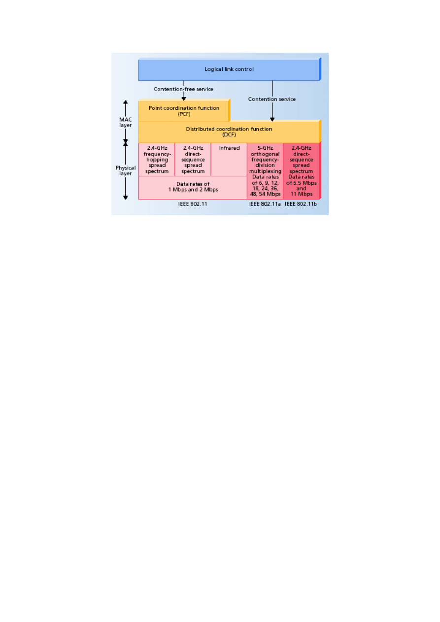
2.2.2 Protocol Layers
The physical layer defines the frequency band, data rate, and other details of the actual radio
transmission. Above the physical layer is the MAC layer that regulates access to the shared
radio frequency band so that station transmissions do not interfere with one another. The
MAC layer has two sub-layers: the lower one is the distributed coordination function (DCF),
which uses an Ethernet-style contention algorithm that provides access to all traffic. Ordinary
asynchronous traffic uses this coordination function (see Section 2.2.4). The upper MAC sub-
layer is the point coordination function (PCF), a centralised MAC algorithm that provides
contention-free service by polling stations in turn. Higher priority traffic—traffic with greater
timing requirements—uses this coordination function (see Section 2.2.4). Finally, the logical
link control layer provides an interface to higher layers and performs basic link layer
functions such as error control (Figure 2-3, adapted from [17, 56]).
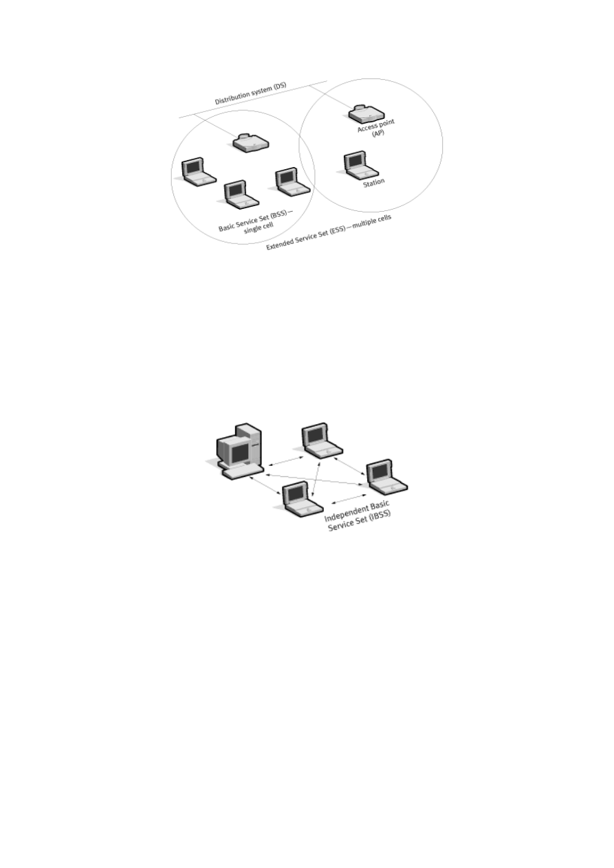
2.2.3 Types of networks
The 802.11 standard defines two modes: infrastructure mode and ad hoc mode. In
infrastructure mode (Figure 2-4), the wireless network consists of at least one AP connected
to the wired network infrastructure and a set of wireless end stations. This configuration is
called a Basic Service Set (BSS). If one mobile station in an infrastructure BSS needs to
communicate with a second mobile station, the communication must take two hops. First the
originating mobile station transfers the frame to the AP. Second, the AP transfers the frame to
the destination station. With all communications relayed through an AP, the basic service area
corresponding to an Infrastructure BSS is defined by the points in which transmissions from
the AP can be received.
9
Figure 2-3: The 802.11 Protocol Stack
Although the multi-hop transmission takes more transmission capacity than a directed frame
from the sender to the receiver, it has two major advantages [9]:
An infrastructure BSS is defined by the distance from the AP. All mobile stations are
required to be within reach of the AP, but no restriction is placed on the distance
between mobile stations themselves. Allowing direct communication between mobile
stations would save transmission capacity but at the cost of increased physical layer
complexity, since mobile stations would need to maintain neighbour relationships
with all other mobile stations within the service area.
APs in infrastructure networks are in a position to assist with stations attempting to
save power. APs can note when a stations enters a power-saving model (see Section
2.2.4) and buffer frames for it. Battery-operated stations can turn the wireless
transceiver off and power it up only to transmit and retrieve buffered frames from the
AP.
An Extended Service Set (ESS) is a set of two or more BSSs forming a single sub-network.
Since most corporate Wireless LANs require access to the wired LAN for services (file
servers, printers, Internet links), they will operate in infrastructure mode. This research uses
the infrastructure mode for the experiments.
10
Figure 2-4: Infrastructure mode
Ad hoc mode (also called peer-to-peer mode or an Independent Basic Service Set, or IBSS) is
a set of 802.11 wireless stations that communicate directly with one another without using an
AP or any connection to a wired network (Figure 2-5). One common use is to create a short-
lived network to support a single meeting in a conference room. As the meeting begins, the
participants create an IBSS to share data. When the meeting ends, the IBSS is dissolved. Due
to their short duration, small size and focused purpose, IBSSs are usually referred to as ad hoc
networks.
Figure 2-5: Ad hoc mode
2.2.4 MAC Layer
Medium Access Control (MAC) is supported by all physical layers. It provides the core
framing operations and the interaction with a wired network backbone. Different physical
layers may provide different transmission speeds, all of which are supposed to interoperate.
802.11 does not depart from the previous IEEE 802 standards in any major way. The standard
successfully adapts Ethernet-style networking to radio links. Similar to Ethernet, 802.11 uses
a Carrier Sense Multiple Access (CSMA) scheme to control access to the transmission
medium. However, collisions waste valuable transmission capacity, so rather than the
Collision Detection (CSMA/CD) employed by Ethernet, 802.11 uses Collision Avoidance
(CSMA/CA) [6]. Similar to Ethernet, 802.11 uses a distributed access scheme with no
centralised controller. Each 802.11 station uses the same method to gain access to the medium.
The major differences between 802.11 and Ethernet come from the differences in the
underlying medium.

11
The following summarises primary 802.11 MAC functions, especially as they relate to
infrastructure wireless LANs [6, 17, 59]:
Scanning:
The 802.11 standard defines both passive and active scanning; whereby, a
radio NIC
5
searches for APs. Passive scanning is mandatory where each NIC scans
individual channels to find the best AP signal. Periodically, APs broadcast a beacon,
and the radio NIC receives these beacons while scanning and takes note of the
corresponding signal strengths. The beacons
6
contain information about the AP,
including SSID
7
and supported data rates. The radio NIC can use this information
along with the signal strength to compare APs and decide upon which one to use.
Optional active scanning is similar, except the radio NIC initiates the process by
broadcasting a probe frame and all APs within range respond with a probe response.
Active scanning enables a radio NIC to receive immediate response from APs,
without waiting for a beacon transmission; however, this will create additional
overhead on the network.
Authentication:
Authentication is the process of proving identity. The 802.11
standard specifies two forms: Open system authentication and shared key
authentication. Open system authentication is mandatory, and it is a two-step process.
A radio NIC first initiates the process by sending an authentication request frame to
the AP. The AP replies with an authentication response frame containing approval or
disapproval of authentication indicated in the Status Code field in the frame body.
Shared key authentication is an optional four-step process that bases authentication on
whether the authenticating device has the correct WEP (wired equivalent privacy)
key
8
. The radio NIC starts by sending an authentication request frame to the AP. The
AP then places challenge text into the frame body of a response frame and sends it to
the radio NIC. The radio NIC uses its WEP key to encrypt the challenge text and then
sends it back to the AP in another authentication frame. The AP decrypts the
challenge text and compares it to the initial text. If they are the same, the AP assumes
that the radio NIC has the correct key. The AP finishes the sequence by sending an
authentication frame to the radio NIC with the approval or disapproval.
Association:
Once authenticated, the radio NIC must associate with the AP before
sending data frames. Association is necessary to synchronise the radio NIC and AP
with important information, such as supported data rates. The radio NIC initiates the
association by sending an association request frame containing elements such as
SSID and supported data rates. The AP responds by sending an association response
frame containing an association ID along with other information regarding the AP.
Once the radio NIC and AP complete the association process, they can send data
frames to each other.
kjjjjjjjjjjjjjjjjjjjjjjjjjjjjjjjjjjjjjjjjjjjjjjjjjjjjjjjjjjjjjjjjjjjjjjjkjjkjkjjkjkjkjj
Privacy:
With a wireless LAN, eavesdropping is a major concern because of the ease
of capturing a transmission [17]. To assure privacy, IEEE 802.11 provides for the
optional use of encryption by specifying a scheme based on the Wired Equivalent
Privacy (WEP) algorithm (see Section 2.4). With the optional WEP enabled, the
wireless NIC will encrypt the body and not the header of each frame before
transmission using a common key, and the receiving station will decrypt the frame
5
Network Interface Card.
6
For more information about beacon frame, refer to [25].
7
Service Set Identifier
8
For more information, see Section 2.4.

12
upon receipt using the common key. The 802.11 standard specifies a 40-bit key and
no key distribution method, which makes 802.11 wireless LANs vulnerable to
eavesdroppers. For stronger protections, some 802.11 vendors offer optional 128-bit
encryption. The 802.11i committee, however, has improved 802.11 security by
incorporating 802.1x and stronger encryption into the standard (see Section 2.5).
s
RTS/CTS:
The optional Request-To-Send and Clear-To-Send (RTS/CTS) function
allows the AP to control use of the medium for stations activating RTS/CTS. With
most radio NICs, users can set a maximum frame length threshold whereby the radio
NIC will activate RTS/CTS. For instance, a frame length of 1,000 bytes will trigger
RTS/CTS for all frames larger than 1,000 bytes. The use of RTS/CTS alleviates
hidden node problems, that is, where two or more radio NICs cannot hear each other
and they are associated with the same AP.
If the radio NIC activates RTS/CTS, it will first send a RTS frame to AP before
sending a data frame. The AP will then respond with a CTS frame, indicating that the
radio NIC can send the data frame. With the CTS frame, the AP will provide a value
in the duration field of the frame header that holds off other stations from transmitting
until after the radio NIC initiating the RTS can send its data frame. This avoids
collisions between hidden nodes. The RTS/CTS handshake continues for each frame,
as long as the frame size exceeds the threshold set in the corresponding radio NIC.
Power Save Mode:
The optional power save mode that a user can turn on or off
enables the radio NIC to conserve battery power when there is no need to send data.
With power save mode on, the radio NIC indicates its desire to enter sleep state to the
AP via a status bit located in the header of each frame. The AP takes note of each
radio NIC wishing to enter power save mode, and buffers packets corresponding to
the sleeping station. In order to still receive data frames, the sleeping NIC must wake
up periodically (at the right time) to receive regular beacon transmissions coming
from the AP.
jkjkjkjjjjjjjjjjjjjjjjjjjjjjjjjjjjjjjjjjkjkjkjkjjkjkjkjkjkjkjkjsdfsdfsdfsdfsdfsfsd
Fragmentation:
The optional fragmentation function enables an 802.11 station to
divide data packets into smaller frames. This is done to avoid needing to retransmit
large frames in the presence of RF interference (see Section 2.3.1). The bits errors
resulting from RF interference are likely to affect a single frame, and it requires less
overhead to retransmit a smaller frame rather than a larger one. As with RTS/CTS,
users can generally set a maximum frame length threshold whereby the radio NIC
will activate fragmentation. If the frame size is larger than the threshold, the radio
NIC will break the packet into multiple frames, with each frame no larger than the
threshold value.
Access to the wireless medium is controlled by coordination functions. Ethernet-like
CSMA/CA access is provided by the distributed coordination function (DCF). If contention-
free service is required, it can be provided by the point coordination function (PCF) that is
built on top of the DCF. Contention-free services are provided only in infrastructure networks.
The coordination functions are described below
9
and illustrated in Figure 2-3.
DCF:
The DCF is the basis of the standard CSMA/CA access mechanism. Similar to
Ethernet, it first checks to see whether the radio link is clear before transmitting. To
avoid collisions, stations use a random backoff after each frame, with the first
transmitter seizing the channel. In some circumstances, the DCF may use the
9
For more information, refer to [6, 23].

13
CTS/RTS clearing technique (mentioned above) to further reduce the possibility of
collisions.
PCF:
Point coordination provides contention-free services. Special stations called
point coordinators are used to ensure that the medium is provided without contention.
Point coordinators reside in APs, so the PCF is restricted to infrastructure networks.
To gain priority over standard contention-based services, the PCF allows a station to
transmit frames after a shorter interval. The PCF is not implemented in the market yet
[6].
2.3
Bandwidth of 802.11 Wireless LANs
The 802.11b standard is generally understood as an 11 Mbps Ethernet LAN running in the 2.4
GHz ISM radio band. Because of the demands of the protocol, and the multiple factors
influencing radio signals, it is very unlikely that the users will ever achieve 11 Mbps as an
operational bandwidth on their LANs. The theoretical throughput can be attained by using
DCF (see Section 2.2.4) as 75% of the nominal bit rate [2], although a target of 65% is
commonly observed. Applying this formula to an 11 Mbps 802.11b network, this yields a
practical throughput in the range of 6 to 8 Mbps. A comparison test was carried out on the
802.11a and 802.11b throughput limits [31]; the author observed the limit for 802.11a was
30.34 Mbps and 6.44 Mbps for 802.11b. The maximum overall throughput of an 802.11b
Wireless LAN in a similar study [40] was reported to be about 6.45 Mbps with a standard
deviation of 0.02 Mbps for a single station. Another study [57] analysed IEEE 802.11
operation under various assumptions such as time-independent modeling, geometrically
distributed packet sizes, etc. Those results also showed that the IEEE 802.11 standard
operates at rates lower than a theoretically possible 7.27 Mbps.
The actual amount of bandwidth is largely dependent on interference and frequency
congestion, as discussed in the next following sections:
2.3.1 Interference
Reduced to its simplest form, wireless networking is a network where the physical wires have
been replaced by radio signals. Unlike wires, radio signals are susceptible to a wide variety of
physical and radio frequency (RF) interference. This interference will normally manifest itself
as a reduction in performance, and occasionally will result in a complete shutdown.
We assume a signal that reaches from point “A”, the wireless AP, to point “B”, the wireless
network interface card in a workstation. The signal might be affected by the following factors
[22, 30]:
Distance (a physical factor):
The closer the wireless device is to the wireless AP,
the stronger the signal, and the better the performance. A stronger signal requires
fewer retransmissions. This is usually only a problem at the edges of the range, but is
a serious consideration for the designer.
Physical barriers such as walls and widows:
These are obvious sources of
interference, but another significant source of interference can result from the
placement of furniture and other objects in the space between points “A” and “B” as
well as the walls that define the space. This kind of interference is called multi-path
propagation. Assuming a line of sight path between points “A” and “B”, a portion of
the signal will go directly between the two antennae. Another portion of the signal

14
will bounce off adjacent walls and furniture, and will arrive at the receiving antenna
some time after the original signal. If the delay is sufficient, the receiving station will
not be able to decode the signal and will not acknowledge the packet, requiring a
retransmission by the sender. This type of interference is most prevalent in a large
space with many reflective surfaces such as a warehouse or manufacturing plant,
however, is certainly not limited to those types of spaces.
Radio frequency (RF) interference:
RF interference involves the presence of
unwanted, interfering RF signals that disrupt normal system operations. The 802.11b
sets the standard for wireless networking in the 2.4 GHz radio spectrum. This
spectrum is known as the ISM (Industrial, Scientific and Medical). It means that there
are also other devices that can radiate radio signals on the same frequency as 802.11b
networking devices. These will include 2.4 GHz wireless telephones, commercial
microwave ovens and Bluetooth devices [30]. Additionally, other 802.11b networks
in close proximity can interfere with a network. As mentioned before in Section 2.2.4,
802.11 devices use CSMA/CA technique when transmitting packets. This means that
they will only transmit when no other device is transmitting. If a device sees another
signal, it will wait for that signal to end before attempting to transmit its packet. If
there is another signal of sufficient strength on the 2.4 GHz band, an 802.11 device
may see it as another 802.11 device and delay transmission. In addition, since these
other radiation sources are not necessarily participating in the protocol, they can start
at any time and interfere with a packet being transmitted. This will result in a
corrupted packet, a subsequent retransmission and hence a poor performance. If the
source of the interference is strong enough and continuous, it can completely shut
down the network.
Geier [30] suggests some actions to be taken in order to avoid RF interference. These will
include analysing the potential for RF interference, preventing them from operating,
providing adequate wireless LAN coverage and setting configuration parameters (such as
frequency channel) properly.
2.3.2 Frequency congestion
802.11b devices share the 2.4 GHz frequency spectrum with a bewildering number of other
radiation sources. The spectrum was originally designated as experimental and its primary
usage was granted to amateur radio. ISM and RF devices were allowed to use the band under
specific rules governing power output and non-interference. RF devices such as 802.11b,
which operate at low power levels, must accept interference from other sources, and may not
interfere with the primary user. As the number of 802.11b implementations increases, so will
the opportunities for interference with other users.
There has already been some studies aiming at developing signaling strategies to minimise
interference between 802.11b and other RF devices in the band [22], but there are some
theoretical limits. The current 802.11b standard allows three channels to operate
simultaneously within the spectrum. In a multi-tenant building, this may be inadequate for the
demand.
In addition to the existing RF devices that can cause interference, RF Lighting is a new
technology that could have a serious impact on frequency congestion. In RF Lighting, a bulb
containing a mixture of argon and sulphur is exposed to a high frequency RF signal causing it
to fluoresce brightly. This technology promises low energy, high output, and long life. It also
operates in the 2.4 GHz band, and may promise additional challenges for 802.11b users
10
.
10
For more information, see
http://wifinetnews.com/archives/001258.html
.

15
A solution to frequency congestion occurrence in the 802.11b band is to migrate to the
802.11a band [22]. This will solve the congestion problem, but at a significant cost since it
will require replacement of both APs and wireless network interface cards, and may force
some re-design because of smaller distance limitations.
Since 802.11 wireless networks use a shared medium, the more devices that are trying to
access it, the lower the effective throughput will be. This is similar to standard wired Ethernet.
When an 802.11 device is transmitting, no other device in the network may transmit data. If
there are multiple devices trying to send large amounts of data, there will be heavy contention
for the airwaves. This congestion gets worse as more machines are added or more data is
being transmitted [16].
2.4
Wired Equivalent Privacy (WEP)
2.4.1 WEP Protocol
Interception of radio communications has been a problem for as long as radios have been used
to transmit sensitive information. Since radio transmissions travel in unsecured areas,
interception of theses radio signals by an attacker is a real threat. In order to protect the data
from eavesdroppers, various forms of encryption have been used.
The 802.11 MAC specification describes an encryption protocol called Wired Equivalent
Privacy (WEP). The goal of WEP is to make Wireless LAN communication as secure as
wired LAN data transmissions. WEP provides two critical pieces to the wireless security
architecture: authentication and confidentiality. It uses a shared key mechanism with a
symmetric cipher called RC4
11
. The key that a client is using for authentication and
encryption of the data stream must be the same key that the AP uses. The 802.11 standard
specifies a 40-bit key, however most vendors have also implemented a 104-bit key for greater
security
12
13
.
Encryption of the data stream provides confidentiality of the data transmitted between two
Wireless LAN devices. The encryption mechanism used in WEP is a symmetric cipher; this
means that the key, which is used to encrypt the data, is the same key that will decrypt the
data. If both wireless LAN devices do not have the same encryption key, the data transfer
fails
14
.
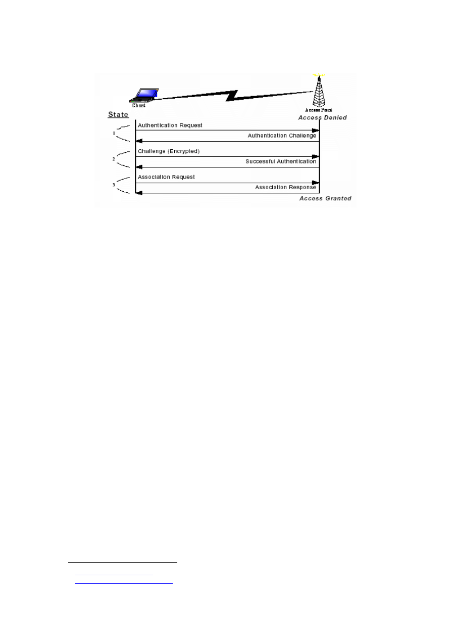
As described in Section 2.2.4, when a station wants to associate with an AP, the station must
authenticate itself to the AP first. When the association occurs, the station and AP exchange
the type of authentication they will accept. If the authentication type is specified as open,
there will effectively be no authentication. The AP and station identify themselves to each
other and the association is complete. The devices may also select the shared secret
authentication mechanism. Station A will send a random number to station B. Station B
encrypts the random umber using WEP and sends the result back to station A. Station A
decrypts the received packet and verifies the decrypted payload equals to random number it
sent to station B. If the numbers match, station A notifies station B that the authentication was
successful and the association is formed (see Figure 2-6, adapted from [5]).
11
Rivest Cipher 4
12
Microsoft Implementation of Windows XP supports 40-bit and 104-bit keys. Both have been
used in the experimental part of this research (see Chapter 3 for more details).
13
It is worthy to note that keys are often based on passwords that are chosen by users; this typically
reduces the effective key size.
14
For more information about WEP encryption, refer to [3, 24].
16
Figure 2-6: Authentication and Association States
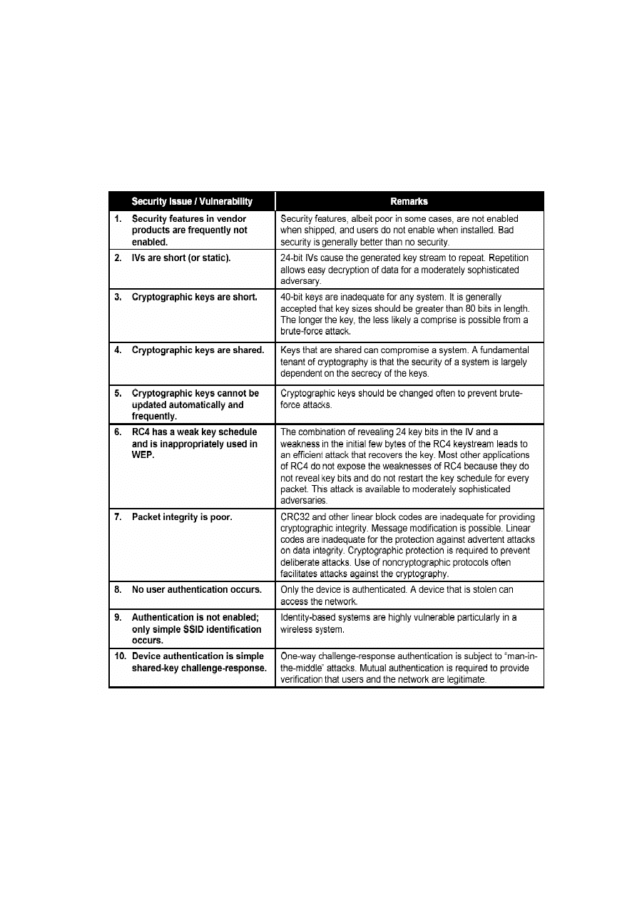
2.4.2 Problems with WEP
There are some known vulnerabilities in the standardised security of the 802.11b Wireless
LAN standard. As mentioned above, the WEP protocol is used in 802.11-based Wireless
LANs. Several groups of computer security specialists have discovered security problems that
let malicious users compromise the security of Wireless LANs. These include passive attacks
to decrypt traffic based on statistical analysis, active attacks to inject new traffic from
unauthorised mobile stations (i.e., based on known plaintext), active attacks to decrypt traffic
(i.e., based on tricking the AP), and dictionary-building attacks [3]. The dictionary building
attack is possible after analysing a full day’s traffic.
Because significant attention is now on
the security of 802.11, more attacks are likely to be discovered. Some of the problems
associated with WEP and 802.11b Wireless LAN security are summarised in Table 2-2
(adapted from [3]).
Fluhrer et al. [15] presented a paper in which the team described a weakness in RC4 as it is
implemented in WEP protocol. The issue is not with RC4, but with the way it is used by
WEP. The end result is that WEP can be cracked if enough traffic can be intercepted. In
addition, as the key length grows, the time it takes grows linearly, while it is supposed to
grow exponentially. There are several freely available tools to crack WEP keys, including
AirSnort
15
and WEPCrack
16
. For more information on WEP flaws, refer to [15, 26, 27].
2.4.3 WEP Improvement
The link layer security provisions in the 802.11 standards are all vulnerable to attacks.
Therefore, systems should deploy additional higher-level security mechanisms such as access
control, end-to-end encryption, password protection, authentication, virtual private networks,
or firewalls [5] and assume WEP as a very basic layer of security only. The IEEE 802.11
committee has set up task group 802.11i [29] to enhance the security and authentication
mechanism of the current 802.11 MAC. Their work has resulted in the development of:
replacement of the 802.11 standard with 802.1x [1, 32] authentication and key
management.
15
http://airsnort.shmoo.com
16
http://wepcrack.sourceforge.net/

17
improvement of the exiting WEP with Temporal Key Integrity Protocol (TKIP), also
known as WEP2.
deployment of Enhanced Security Network (ESN) solution with a stronger encryption
algorithm
17
.
As described above, one of the major security issues with WEP is the challenge of distributing
and managing the encryption keys. The 802.1x standard has been introduced to provide a
centralised authentication and dynamic key distribution for 802.11 architecture using the
802.1x standard with RADIUS [7]. 802.1x—a collaborative effort by vendors in the software,
server, and networking industries—is an authentication standard for 802-based LANs using
port-based network access control. It is used for communication between wireless clients and
APs, while RADIUS operates between an AP and an authentication server. Industry leaders
proposed 802.1x to address WEP vulnerabilities by providing access control and key
distribution to any (wired or wireless) Ethernet
port.
The 802.1x standard will be discussed in
more details in Section 2.5.
17
For information on WEP2 and ESN, refer to [28, 29].
18
Table 2-2: Key Problems with WEP (the default 802.11 Wireless LAN Security)
19
2.5
IEEE 802.1x Security Protocol
The security structure in 802.11, including WEP and WEP-based authentication, is not
designed to scale to handle large, public networks [34]. The shared key design in WEP
requires the network administrator to trust many users with the same authentication
credentials for the same set of APs.
802.1x, a ratified IEEE standard, solves some but not all of these problems. 802.1x is a port
based, extensible authentication protocol. It was designed to prevent an attacker from
malicious use of the network.
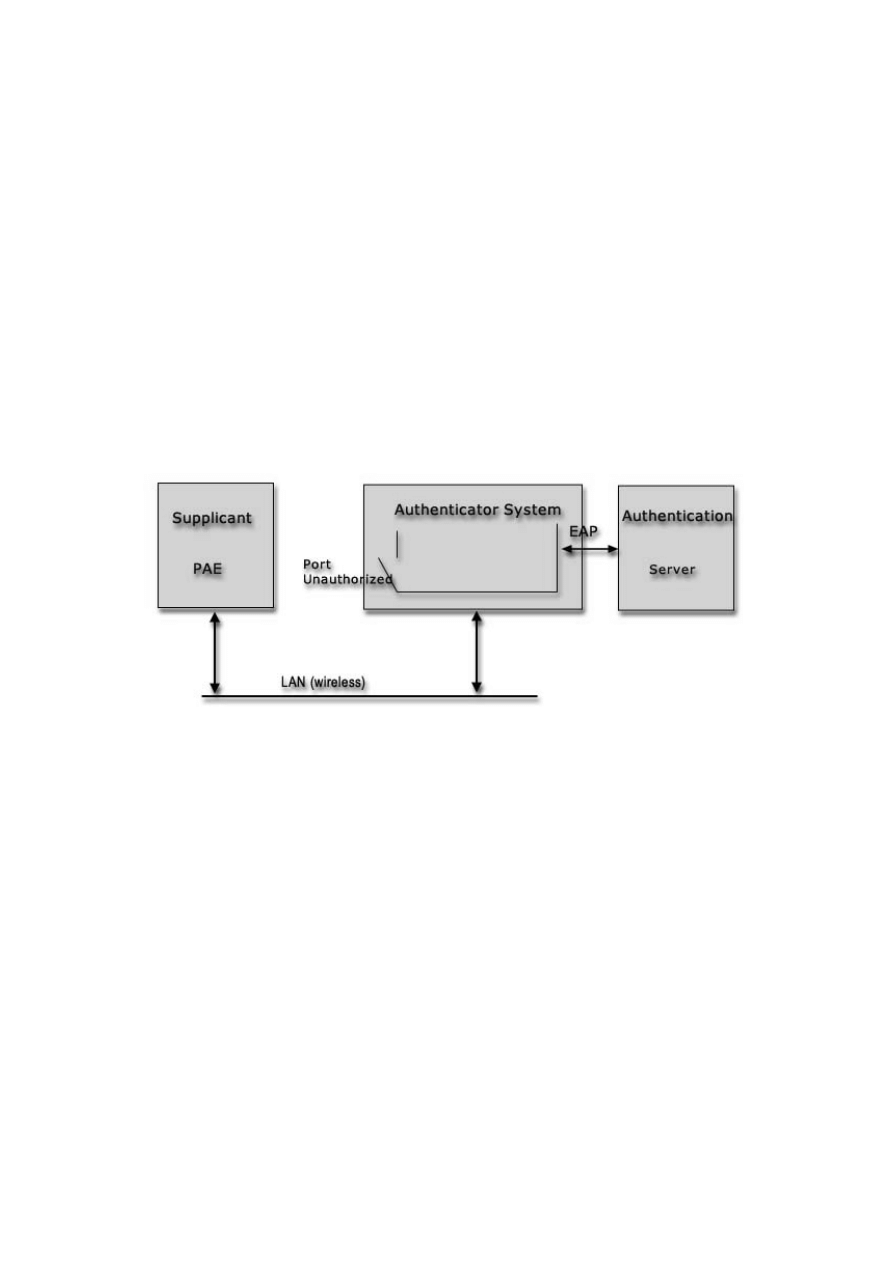
2.5.1 Terminology
Figure 2-7 (adapted from [10]) shows the supplicant, authenticator system, and authentication
server in an 802.1x wireless network. 802.1x requires one authenticator per port. The
controlled port shown below is not authorised and is therefore not allowing traffic.
Figure 2-7: The 802.1x Basic Scenario
Port:
A port is a single point of attachment to the LAN infrastructure. In the 802.11 LAN case,
an AP manages logical ports. Each of these logical ports communicates one-to-one with a
station’s port.
Authenticator System:
The authenticator enforces authentication before allowing access to
services that are accessible via that port. The authenticator is responsible for communication
with the supplicant as well as submitting the information received from the supplicant to a
suitable authentication server. This allows the verification of user credentials to determine the
consequent port authorisation state. It is important to note that the authenticator’s
functionality is independent of the actual authentication method. It effectively acts as a pass-
through for the authentication exchange.
Supplicant:
The supplicant accesses the services accessible via the authenticator. The
supplicant is responsible for responding to requests from an authenticator for information,
which establishes its credentials.
EAP:
The Extensible Authentication Protocol (EAP) [43] is a method of conducting an
authentication conversation between a user and an authentication server. Intermediate devices
such as APs and proxy servers do not take part in the conversation. Their role is to relay EAP

20
messages between the parties performing the authentication. 802.1x employs the EAP as an
authentication framework.
Extensible Authentication Protocol over LAN (EAPOL):
802.1x defines a standard for
encapsulating the EAP messages so that they can be handled directly by a LAN MAC service.
This encapsulated form of EAP frame is known as EAPOL. In addition to carrying EAP
packets, EAPOL also provides control functions such as start, logoff, and key distribution.
RADIUS:
RADIUS is the Remote Access Dial In User Service. It is the standard way of pro-
viding Authentication, Authorisation and Accounting services to a network. Although
RADIUS protocol support is optional within IEEE 802.1x, it is expected that many 802.1x
authenticators will function as RADIUS clients.
2.5.2 802.1x Architecture
802.1x port-based access control has the effect of creating two distinct points of access to the
authenticator’s attachment to the LAN. One point of access allows the exchange of frames
between the system and other systems on the LAN. Often, this uncontrolled port allows only
authentication messages (EAP messages) to be ex-changed. The other (controlled) point of
access allows the exchange of frames only if the port is authorised.
When a host connects to the LAN port on an 802.1x switch the authenticity of the host is
determined by the switch port according to the protocol specified by 802.1x before the
services offered by the switch are made available on that port. Until the authentication is
complete, only EAPOL frames are allowed exchanged. Once the host authentication is
successful, the port switches traffic as a regular port. As previously mentioned, 802.1x was
developed to address point-to-point networks. In other words, there must be a one-to-one
relationship between a supplicant and an authenticator. In a wired LAN, a supplicant is
directly connected to an authenticator. As shown in Figure 2-7, a workstation is directly
connected to a LAN switch port. Each port on the LAN switch has an associated authenticator.
The workstation gains access to the network when its supplicant authenticates to the LAN
port authenticator [10, 33].
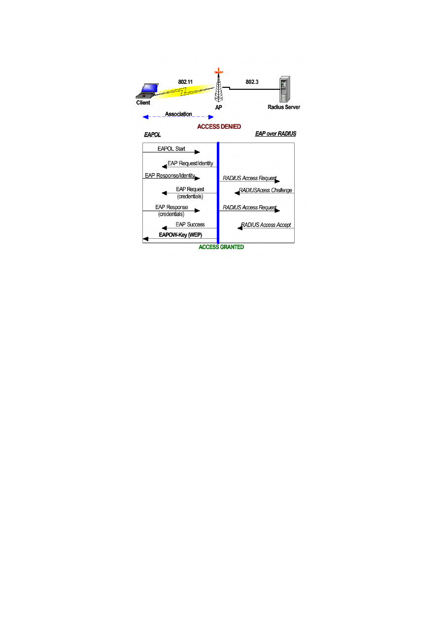
2.5.3 802.1x in 802.11 Wireless LANs
Applying the 802.1x structure to the 802.11 network architecture (Figure 2-8, adapted from
[5]) provides a controlled wireless network with user identification, centralised authentication,
and dynamic key management. Dynamic key management in an 802.1x framework rectifies
the drawbacks in the WEP security mechanism by deploying per-user session keys.
The 802.1x neither excludes nor requires WEP or any other encryption algorithm. It provides
a mechanism for distributing encryption key information from an AP to a client using the
EAPOL-Key message. Once the station is associated with an AP, it can exchange EAP
messages with the authentication server to authorise the port. Before the logical port has been
authorised, it only exchanges EAP messages.
One session key can be derived for each user per session. However, if global keys (WEP
keys) are used, the session key sent from the authentication server to the AP is the only used
to encrypt the global key; therefore providing per-packet authentication and integrity. An
EAPOW-key packet is used for the global keys.
21
Figure 2-8: 802.1x over an 802.11 Network
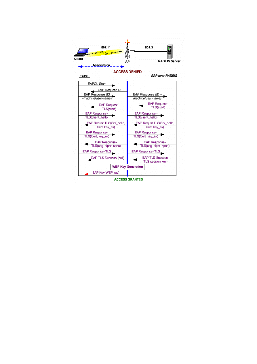
2.5.4 EAP-TLS
EAP-TLS [36] is the most commonly implemented EAP type for wireless LANs. It provides
secure mutual authentication using digital certificates. When a client requests access, the
response from the authentication server is a server certificate. The client has a certificate,
signed by a trusted certificate authority, which has been preconfigured by the network
administrator. The client will reply to the authentication server's challenge with its own
certificate and validates the server certificate at the same time. Based off the certificate values,
the EAP-TLS algorithm can derive dynamic WEP keys, and the authentication server will
send the client the WEP key for use during that session.
Certificate-based algorithms such as EAP-TLS are highly secure, as it is nearly impossible to
forge a certificate digitally signed by a certificate authority. On the other hand, the
management of certificates can be complex and expensive [1]. Thus, depending on the scale
of an organisation’s network, administrative burdens might outweigh the security advantages.
Figure 2-9 (adapted from [5, 58]) illustrates the process.
2.6 Wireless
Performance
Security is a property of an entire system and every decision must be examined with security
in mind [26]. There have been many evaluation studies of IEEE 802.11 wireless network
performance; however, little attention has been paid to the effects of implementing security on
performance. Some relevant evaluation studies have been described in this section. Chapter 3
also introduces some related work in this area in order to justify the design and parameters
used in this research.
22
Figure 2-9: EAP-TLS Authentication Process
Amaro et al. [41] evaluated the performance of wireless networks and concluded that, the
larger the packet size, the higher the effective rate. The collision avoidance mechanism of
802.11b protocol confirmed this increase, as traffic overheads introduced by the control
frames RTS/CTS (see Section 2.2.4) and the ACK frames diminished for larger packets.
A number of tests, described by [39], conducted on the 802.11 wireless LANs to measure
performance characteristics (throughput and response time) of the MAC layer under various
network loads. The results showed that the buffering and fragmentation of data frames can
seriously influence the performance of an 802.11 wireless LAN. Although the length of a data
frame and the bit rate of the wireless transceiver also affect the wireless LANs transmission
capabilities, its performance is generally unaffected by the type of frame addressing and the
use of reservation frames such as RTS and CTS.
Chen [11] carried out an experiment to compare the coverage area and performance between
802.11b (11 Mbps) and 802.11a (54 Mbps). The study showed that 802.11a provides 2-to-5-
times better data-link rate and throughput performance in the same range (77m) as 802.11b.
Chen also compared the trade-off between performance and costs in terms of range and total
system capacity. 802.11a offered better system capacity with fewer cells (APs).
Empirical results from [55] demonstrated that different modes of 802.11 wireless LAN and
Ethernet frame size were crucial factors in the determination of a wireless LAN’s
transmission capabilities. The throughput of a wireless LAN increased as the frame length

23
increased and as the amount of broadcast traffic decreased. Furthermore, the authors
suggested that the mean response times for both wired and wireless LANs were similar, with
an inter-frame delay of 10 ms or more.
An empirical characterisation of the instantaneous throughput of a station in an 802.11b
Wireless LAN, as a function of the number of competing stations sharing the AP, was
presented in [40]. The results showed that as the number of stations increases, the overall
throughput decreases and its variance increases.
Kamerman et al. [42] evaluated the throughput of 802.11 wireless LANs with respect to
various kinds of overhead. The impact of several sources of overhead was modeled. Sources
included gap time, preamble, physical layer, MAC layer and TCP/IP header fields, ACK and
request frames. After measurement of the net throughput and detailed monitoring of actual
exchange of frames, this modeling was refined. A close fit was found between the results for
IEEE 802.11b obtained from this model and as measured using currently available 2.4 GHz
products.
A recent study [5] evaluated the security performance of an 802.11 wireless network, by
measuring the throughput and response time of HTTP and FTP traffic types in an unsaturated,
simple point-to-point architecture. The results showed that the stronger the security
mechanism implemented, the poorer the network performance. The study recommended using
multiple clients (in order to experiment with congestion in a secure environment), and looking
at a wide range of traffic types. These recommendations were used as the basis for this
research. The research also evaluated the performance of wireless LANs at the packet level,
as described in next chapter.

24
Chapter 3
Experiments
3.1 Aim
This aim of this research is to investigate the performance and security issues of 802.11b
wireless LANs with multiple clients, hence demonstrating contention in a secure environment.
The following issues are addressed in particular:
How do different security mechanisms affect the performance (delay and throughput)
of a congested wireless LAN with multiple clients?
What are the effects of different packet lengths on the performance of wireless LANs
using different security mechanisms?
What is the impact of security on different traffic types?
How does the performance of a secure network vary by adding more clients?
3.2 Method
3.2.1 Design Considerations
There were a few design decisions made before carrying out the experiments. The main three
were related to security layers, the traffic generator and the performance measurements used
in the experiments. They are described below:
Defining Security layers
As part of the research objectives, we wanted to experiment with the effect of WEP
authentication and encryption as well as IEEE 802.1x authentication. The security layers,
therefore, had to be defined in a way that they would include all the possibilities.
Traffic Generator
As mentioned in Section 3.1, this research focuses on the performance evaluation of
congested wireless LANs. The generator had to be flexible and capable of overloading such
networks. The specific requirements we had in mind for choosing a traffic generator were:
Suitable for wireless networks
Capable of overloading an 802.11 LAN
Allowing the user to change the size and inter-packet delay
Allowing the user to select the generation algorithm
25
Measuring performance
Many factors affect network performance and some of them interact to provide overall
performance results. Performance results vary depending on the choice of hardware device,
software application and network topology [5]. Some of the performance measurements are
[49, 50]: Response time, Throughput, Coverage area, Mobility, Bandwidth, Latency, Radio
signal strength, etc. Response time and Throughput were measured in this research to provide
a comprehensive view of the network performance
18
. They are defined as follows:
Response time:
the total time required traffic to travel between two points. It
includes the time of dial-up connection establishment, security negotiation time
between the server and the clients and the actual data transfer.
Throughput:
the total number of bytes transmitted over the network in a given time
(response time).
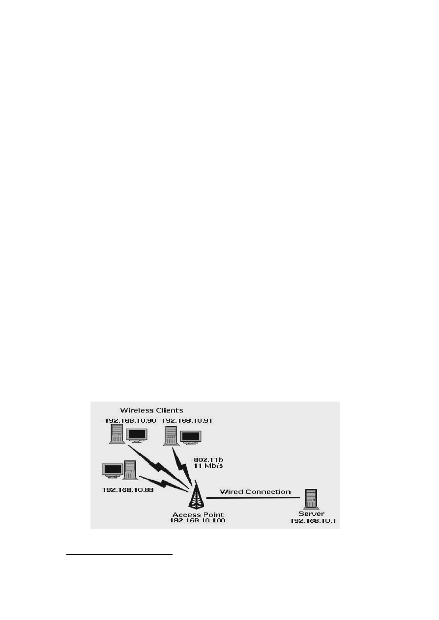
3.2.2 Configuration of Wireless LAN system
It was decided to use Windows-based operating systems, since Windows XP has a built-in
implementation of the IEEE 802.1x authentication protocol [51]. As shown in Figure 3-1, the
experiments were conducted using:
One Server
o
Windows 2000 Advanced server
o
1.4 GHz, 512 MB RAM, Orinoco AP-2000 software
Three Clients
o
Windows XP Professional
o
1.4 GHz, 512 MB RAM, Orinoco USB client and ORiNOCO Wireless LAN
Gold Cards
Access Point
o
Lucent Orinoco AP-2000
Figure 3-1: Experimental set up
18
These two parameters have been measured in other wireless performance studies, such as [39].

26
Transmission speed was 11 Mbps wireless connections between the AP and the clients and
100 Mbps Ethernet connections between the AP and the server. Ethereal
19
Network Analyser
was used to capture live network statistics. The measurements were collected from the server.
Appendix B provides instructions on implementing security mechanisms
20
and further
enhancing the system architecture used in [5] to support multiple clients.
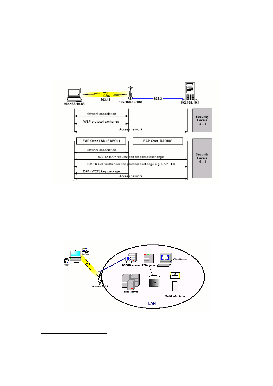
3.2.3 Security Layers
The following eight security layers were chosen to present a hierarchical order of the security
mechanisms available from both IEEE 802.11 and IEEE 802.1x standards (For more details
about each protocol, see Sections 2.4, 2.5):
1.
No security:
this is the default security setting provided by vendors. There is no
security mechanism activated with default configuration.
2.
MAC address authentication:
this layer provides MAC address authentication
carried out at the AP.
3.
WEP authentication:
the shared key authentication method specified in the
802.11 standard is used.
4.
WEP authentication with 40-bit WEP encryption:
this layer combines the
encryption algorithm to provide data privacy.
5.
WEP authentication with 128-bit WEP encryption:
the 128-bit shared key used
is proprietary-based (in the case of Lucent).
6.
EAP-TLS authentication:
this is the PKI-based authentication method supported
by 802.1x, using digital certificates to authenticate the user
21
.
7.
EAP-TLS with 40-bit WEP encryption:
the combined effect of these tools
provides the strongest layer of encryption and authentication using per-session
keys.
8.
EAP-TLS with 128-bit WEP encryption:
this layer is the same as above using
128-bit keys.
The first five security layers are consistent with the 802.11 standard. Security layers 6 to 8 are
provided by the 802.1x standard.
3.2.4 802.1x Model Implementation
The 802.1x model consisted of the 802.11 access mechanism using open and shared key
authentication, WEP encryption, and the 802.1x port-based authentication. By combining
802.1x with 802.11 protocols (as security layers 6 to 8), the model provided a controlled
wireless network with user identification, centralised authentication, and dynamic key
management.
For security layers 6 to 8, a RADIUS server was used to provide dynamic key management
and centralised authentication (see Figure 3-2, where the server and one of the clients shown).
19
http://www.ethereal.com/
20
In this report security layer and security mechanism represent the same concept.
21
For further details, refer to section 2.5.4.
27
The authentication method chosen for the experiments was EAP-TLS. The 802.1x model does
not support end-to-end security, because privacy and confidentiality were only ensured on the
wireless link by the WEP, but not enforced on the wired counterparts.
Wireless users were treated as if they existed in one sub-network of an organisation’s intranet.
Specific IP addresses were assigned to the wireless users, AP and different components of the
server.
Figure 3-2 802.1x Model Logical Flow
The RADIUS server and certificate authorities were added to the basic network structure to
provide the 802.1x authentication support (Figure 3-3). The RADIUS server supported
wireless user sign-on, and a certificate authority was used to issue certificates to users for
EAP-TLS authentication
22
.
Figure 3-3 802.1x Model Implementation
22
This section is a modified version of a section from [5]; the approach taken in implementing 802.1x
model by this research and [5] are relatively similar.
6 - 8
28
3.2.5 Traffic generator
We were interested in the ability of a wireless LAN to transfer IP packets in a predefined
number, size, content and bandwidth in order to measure the variation in performance when
security mechanisms are implemented.
After spending a considerable amount of time searching for an appropriate traffic generator,
IP Traffic
23
tool was found. It was felt that this generator had met all the requirements we had
in mind (see Section 3.2.1). IP Traffic is a software-testing tool that is designed for both fixed
and wireless IP networks and runs on Windows platforms. It can generate, receive, capture
and replay IP traffic, and measure end-to-end performance and Quality of Service over any IP
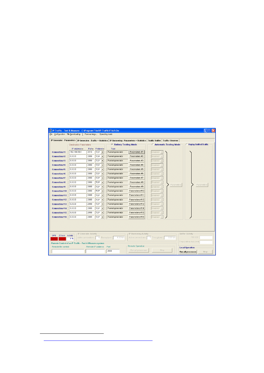
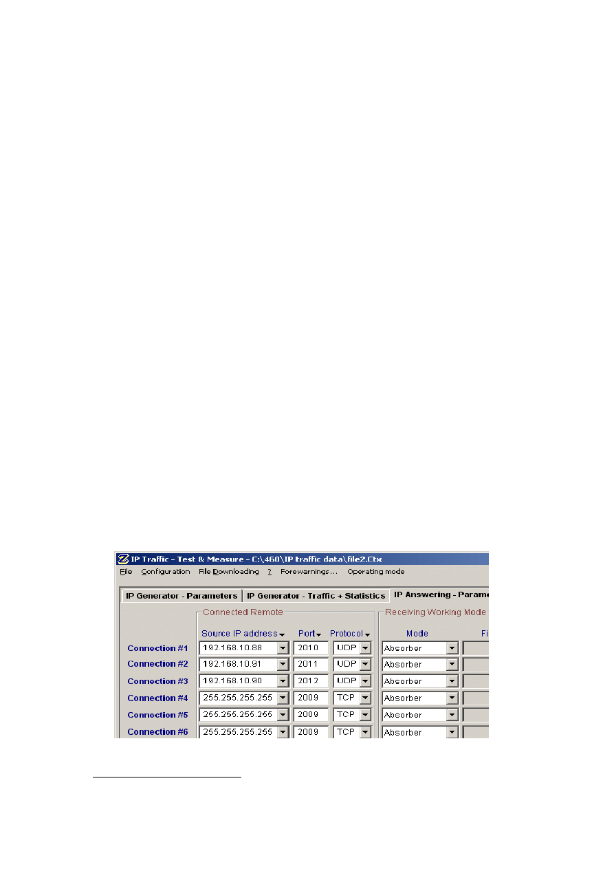
fixed or mobile network. The generator can manage several simultaneous IP connections (see
Figure 3-4); however, we only used one active connection from each client to model a more
realistic situation. We used the real time statistics generated by IP Traffic as well as the data
collected by Ethereal on the server side to evaluate the performance of the wireless network.
Figure 3-4: IP traffic tool on client side
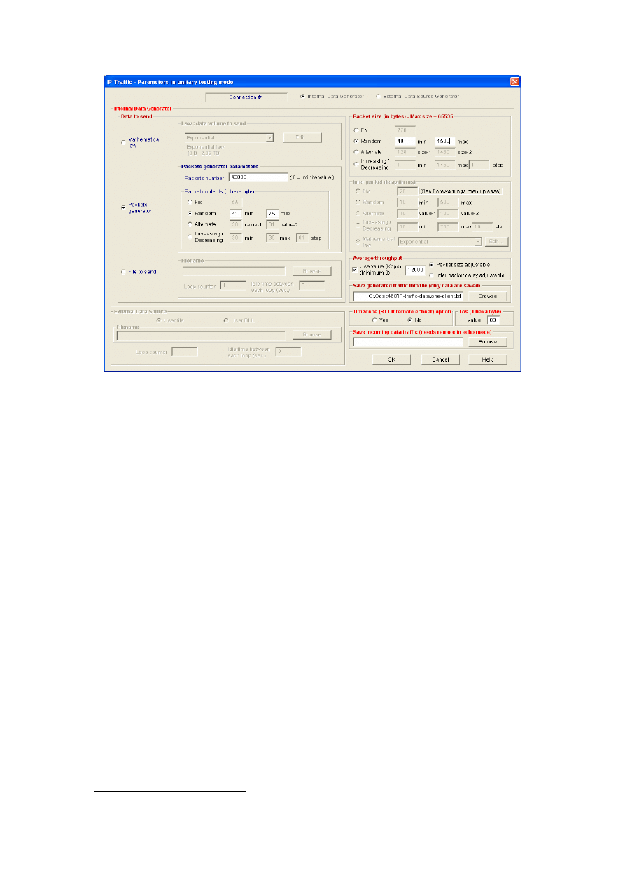
The following describes and justifies the parameters specified in the generator for the duration
of the experiments (see Figure 3-5):
Total number of packets
Preliminary experiments showed that the choice of packets number did not affect the trends
observed in the results. Ranges between 10000 and 60000 were tried and 43000 was selected
as an arbitrary value between the two.
23
http://www.zti-telecom.com/pages/iptraffic-test-measure.htm
29
Figure 3-5: Parameters specified for each connection
Outgoing bandwidth
The incoming bandwidth of an 802.11b Access Point is 11 Mbps (according to standards).
Since we were interested in the behaviour of networks under congestion, we decided to set the
outgoing bandwidth of each client to be 12 Mbps—well in excess of the published 802.11
maximum to ensure a congested scenario.
Traffic type
It was decided to experiment with TCP and UDP protocols, as these protocols form the basis
of all the applications running on the IP protocol stack. Other studies have evaluated the
performance of TCP and UDP protocols over wireless networks (e.g. [40, 44, 52]). However,
none of them took the impact of different security mechanism into account.
Content
Content of each packet was decided to be random. This parameter was not of any importance
in this research.
Packet length
It was decided to set the packet length to be a random integer uniformly distributed over the
interval [40, 1500] in the first set of experiments. The main advantage of this traffic model is
that it allows exploring the full range of packet sizes [46]. It was decided to choose 40 and
1500 bytes as boundaries of IP packet sizes, as these numbers have been used in previous
woks [44, 45, 48]. In addition, these values were chosen after capturing live traffic on a
COSC LAN for 3 days
24
using Ethereal and considering the packet sizes. Random generation
24
This was done on July 8-10, 2003.
30
of packet lengths compared with using fixed sizes (in the first set of experiments), provided us
with more realistic situation.
In the second part of experiments (studying throughput as a function of packet sizes), four
fixed packet sizes (i.e. 100, 500, 1000, 1500) were selected and the experiments were
conducted using each value at a time. These values have been used in other performance
studies such as [44, 52].
3.3 Procedure
As described in Section 3.1, this research aims to evaluate the effect of different security
mechanisms and packet sizes on the performance of a congested wireless LAN with multiple
clients.
In the first set of experiments, the throughput and response times of two traffic types (TCP
and UDP) were measured under different security mechanisms. The experiments were then
repeated for two and three clients to study the impact of adding more clients. Two different
bandwidths were defined: 12000 kb/s (to represent a congested network) and 500 kb/s (to
represent an unsaturated network). It was decided to set the packet length to be a random
integer uniformly distributed over the interval [40, 1500], as stated in the previous section.
The security layers, traffic generator and the system configuration used during the
experiments are detailed in Section 3.2. Figure 3-6 illustrates the configuration of traffic
generator on the server side, where the clients’ IP addresses were manually allocated.
Appendix B provides instructions on setting up the system.
In the second set of experiments, the throughput was studied as a function of different packet
sizes, under different security mechanisms. The packet sizes were divided into four fixed
numbers, i.e. 100, 500, 1000, 1500, as described before. The experiments were conducted
using one client and three different security mechanisms
25
, and throughput was measured for
both TCP and UDP traffic types. Results are discussed in Section 3.4.
Each experiment was repeated eight times. Due to system factor influences (memory caching
and disk pages), it was decided to discard the first three results, to exclude system factors.
Figure 3-6: Configuration set up on server side
25
Chosen from the eight mechanisms, listed in Section 3.2.3.
31
3.4 Results
The experiments followed the eight security layers described in section 3.2.3. An
infrastructure mode of operation and a single cell were used with three clients. Performance
measures were gathered by running five repetitive tests at each security configuration.
Experiments evaluating the performance of TCP were separated from UDP’s and each set was
conducted for different number of clients. Results were collected through log files generated
by the traffic generator and the Ethereal monitoring tool. Data were analysed, at the
corresponding 95% confidence interval.
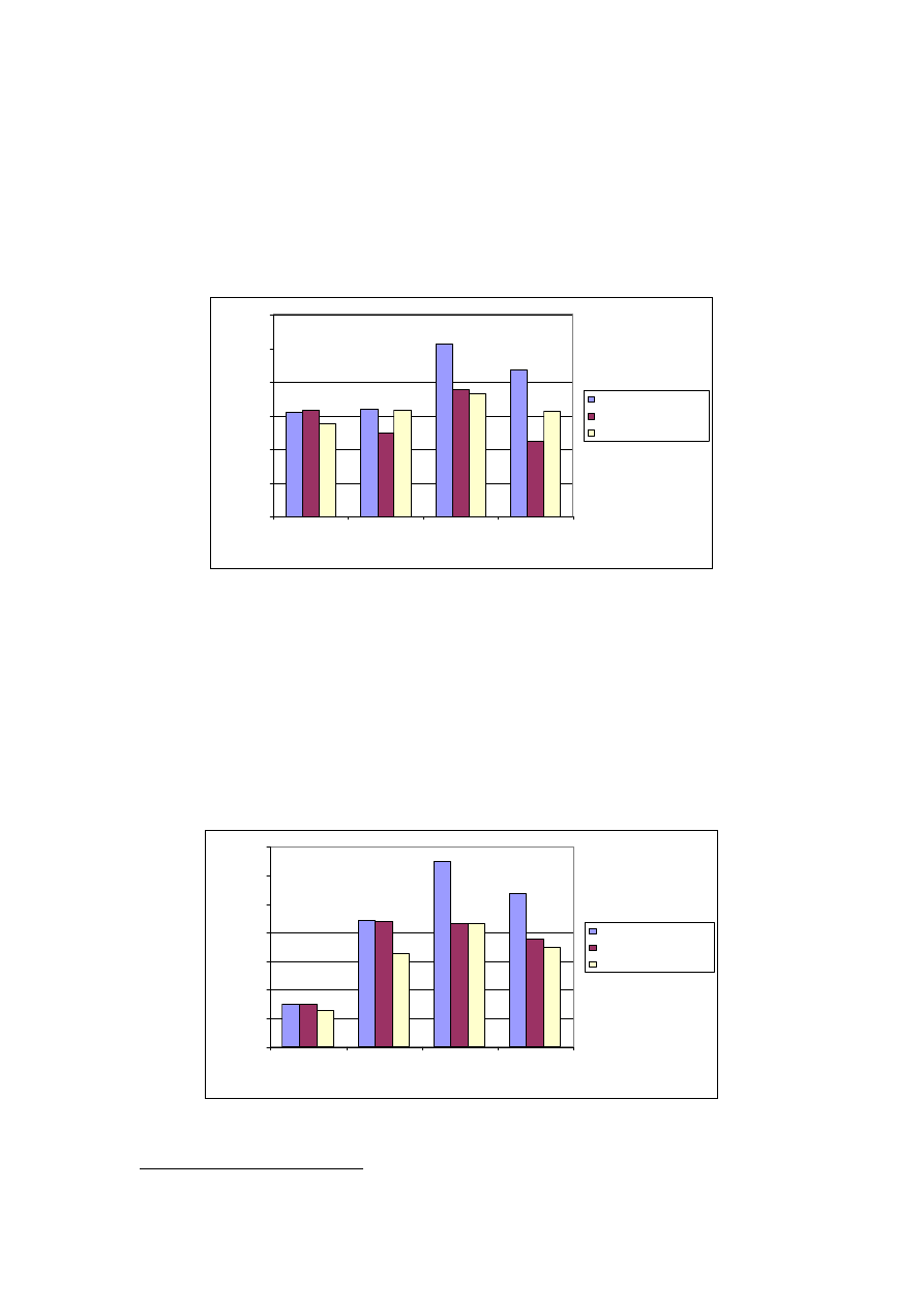
3.4.1 Effect of security mechanisms on performance
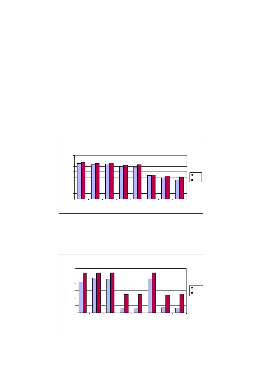
In the first part of the experiments, the bandwidth was set to 500 Kb/s to represent a lightly
loaded network (in other words, normal situation when the network is not congested). Figure
3-7 illustrates the throughput of TCP and UDP traffic types under different security layers,
discussed in Section 3.2.3. These results confirmed the general trends reported in [5],
meaning that the stronger the security mechanism implemented, the poorer the network
performance.
Av e rage Pe rformance
0
10
20
30
40
50
60
70
80
1
2
3
4
5
6
7
8
Se curity La ye r
N
e
tw
o
rk
Th
ro
ug
hp
ut
(
K
B
/s
)
TCP
UDP
Figure 3-7: Throughput of TCP, UDP traffic in an unsaturated network
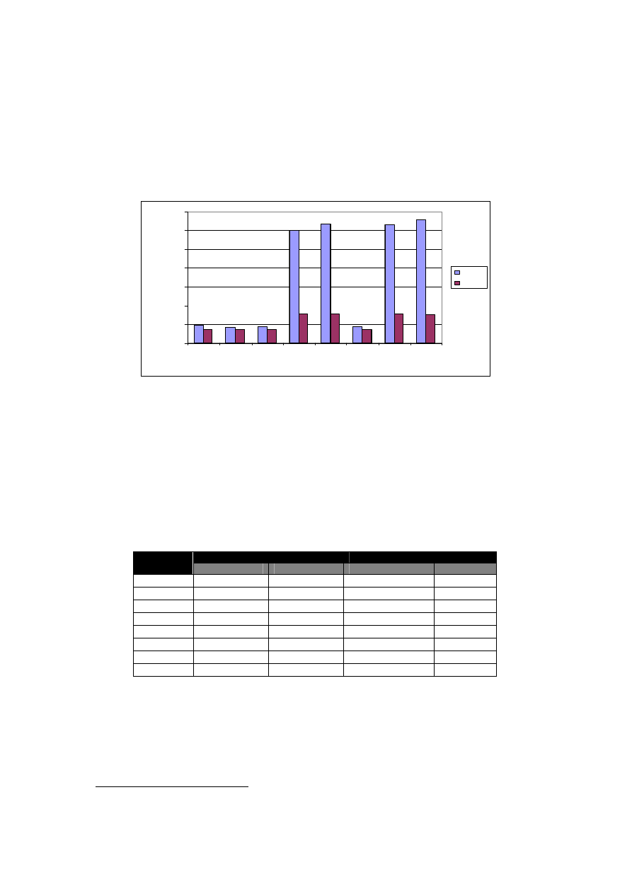
Figure 3-8 and 3-9, on the other hand, illustrate the throughput and (per-packet) response
times of TCP and UDP traffic types when the network is congested (bandwidth is set to 12
Mb/s).
Average Throughput
0
100
200
300
400
500
600
1
2
3
4
5
6
7
8
Security Layer
N
e
tw
or
k
T
h
ro
ug
hp
ut
(
K
B
/s
)
TCP
UDP
Figure 3-8: Throughput of TCP, UDP traffic in a congested network
32
As the graphs show, the performance of a congested network at security layers 4, 5, 7 and 8
(WEP encryption is in place) is significantly less than the performance of the network at
security layers 1, 2, 3 and 6. The security layers 4, 5, 7 and 8 decrease the TCP throughput by
86.1% and the UDP throughput by 54.3% (on average). In addition, they increase the TCP
response time by 86.2% and UDP response time by 51.9%. The results show that in congested
networks, the overhead produced by encrypting each individual packet (implemented at
security layers 4, 5, 7 and 8), is significantly higher than applying more advanced
authentication methods, such as EAP-TLS protocol implemented at security layer 6
26
.
0
2
4
6
8
10
12
14
1
2
3
4
5
6
7
8
S e curity La ye r
M
e
a
n
R
e
sponse
Ti
m
e
(
m
s)
TCP
UDP
Figure 3-9: Per-packet response times of TCP, UDP traffic in a congested
network
The performance of TCP and UDP can also be compared. Since the TCP protocol uses a
congestion control mechanism, it is significantly slower than the UDP protocol in congested
networks, especially when WEP encryption is applied. The TCP throughput is 21.6% of UDP
throughput at security layers 4, 5, 7 and 8 and 85.5 % of UDP throughput at security layers 1,
2, 3 and 6.
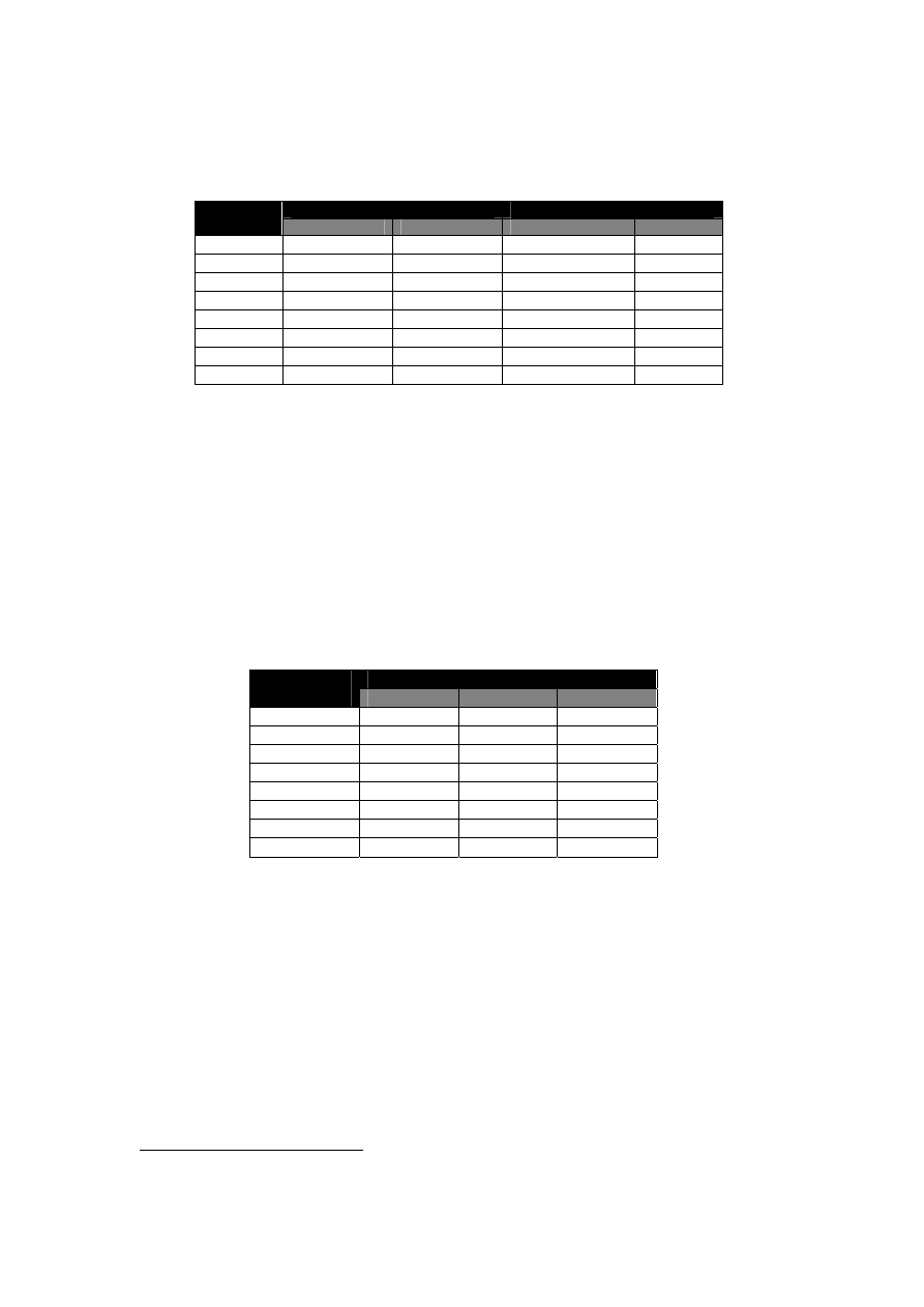
Table 3-1 and 3-2 show the mean and standard deviation of TCP and UDP throughput and
response times when the wireless LAN is congested.
TCP
UDP
Security
Layer
Mean
SD
Mean
SD
1 447.5200
7.3095
535.6960
0.2218
2 470.7520
4.3070
535.0120
1.0143
3 464.4460
11.5685
536.5260
4.0540
4 67.2940
1.7635
245.4660
0.3958
5 63.7380
1.8943
245.6100
2.0043
6 454.6480
0.4346
539.4560
5.4398
7 64.3000
2.1949
244.3340
0.7835
8 61.5300
1.9546
245.8260
3.2859
Table 3-1: The Mean and SD of TCP and UDP throughput under different security
mechanisms
The security layers significantly differ from each other in their effects on the throughput of
the network for TCP (
F (7, 28) = 8558.155, p < .001
) and UDP (
F (7, 28) = 14155.207, p < .001
)
26
This is not the case in unsaturated networks (shown in Figure 3-7), as the network performance at
layer 6 (EAP-TLS authentication) is lower than layer 5 (WEP encryption with 128-bit keys).
33
traffic types. The security layers also significantly differ from each other in their effects on
the response time of the network, for both TCP (
F (7, 28) = 2439.143, p < 0.001
) and UDP (
F (7,
28) = 9103.760, p < 0.001
)
traffic. The data that are used for ANOVA analysis, are based on
Appendix A Captured Data
27
.
TCP
UDP
Security
Layer
Mean
SD
Mean
SD
1 77.2240
0.7888
64.4800
0.1049
2 73.5660
0.7748
64.5200
0.2233
3 75.2880
1.9601
64.6400
0.6479
4 520.7700
13.9539
134.0740
0.1266
5 546.7900
20.1678
134.3780
0.9191
6 76.4840
0.0568
63.8280
0.5364
7 549.8400
20.6787
134.7220
0.4132
8 573.6260
9.5460
131.7140
2.0734
Table 3-2: The Mean and SD of TCP and UDP response times under different security
mechanisms
3.4.2 Effect of adding more clients
To evaluate the performance of the network in a secure multi-client environment, the
experiments were repeated using two and three clients. Table 3-3 shows the average per-
station throughput for UDP traffic. Over all security layers, the average throughput of each
station decreased by 49.5% when the experiments were conducted using two clients and
66.5% when using three clients.
28
Per – station throughput (KB/s)
Security
Layer
1 Client
2 Clients
3 Clients
1 535.68
279.55
176.79
2 535.44
273.07
178.97
3 539.37
269.6
185.77
4 245.61
120.37
78.89
5 245.28
122.88
84.14
6 540.13
273.06
178.28
7 244.45
121.73
79.61
8 248.17
122.09
84.78
Table 3-3: Average per-station throughput for UDP traffic
When WEP encryption was not enabled (under security layers 1, 2, 3 and 6), UDP packet loss
rates were 3.2%, and 0.6 % for TCP packet. The UDP drop rate increased by 3.6% when
WEP encryption was enabled (security layers 4, 5, 7 and 8), while only increasing 0.2% for
TCP traffic. On average, the observed results were increased by 0.4% when the number of
clients was increased to three.
Our experiments validate the results reported in [40], which presented an empirical
characterisation of the instantaneous throughput of a station in an 802.11b Wireless LAN, as a
function of the number of competing stations sharing the AP. The results showed that as the
number of stations increases, the overall throughput decreases and its variance increases.
27
Appendix A provides the data collected for one client.
28
Same results were observed for TCP traffic type.
34
However, that study did not take into account the effect of having different security
mechanisms
29
in place.
3.4.3 Effect of various packet sizes on performance
As described in Section 3.3, four fixed packet sizes, i.e. 100, 500, 1000, 1500 bytes were
chosen in order to evaluate their impacts on the throughput of a congested wireless LAN
under different security mechanisms.
0
100
200
300
400
500
600
100
500
1000
1500
Pa cke t Size (Byte )
N
e
tw
o
rk
Thr
ou
ghput
(
K
B
/s
)
MAC
W EP E
W EP E + 802.1x A
Figure 3-10: TCP throughput for different packet sizes
As Figure 3-10 shows, the throughput of TCP traffic is maximum when the packet size is set
to 1000 bytes and this is the case for the three security layers chosen (MAC authentication,
WEP Encryption with 128-bit keys, and WEP Encryption combined with 802.1x
authentication).
Figure 3-11 shows similar results for UDP throughput. The throughput has the highest value
when the packet size is set to 1000 bytes, at first and third security layer. When the 2
nd
security layer is implemented (WEP encryption) packet size of 500 and 1000 bytes have
almost the same throughput, with 0.1 KB/s difference (as shown in Table 3-5).
0
100
200
300
400
500
600
700
100
500
1000
1500
Pa cke t Size (Byte )
N
e
tw
or
k
T
h
ro
ug
hp
ut
(
K
B
/s
)
MAC
W EP E
W EP E + 802.1x A
Figure 3-11: UDP throughput for different packet sizes
29
As detailed in section 3.2.3

35
Packet
Size (Byte)
MAC
Authentication
WEP
Encryption
WEP Encryption +
802.1x Authentication
100 150.81
147.69
130.18
500 443.29
439.7
327.26
1000 648.82
439.8
434.67
1500 538.01
375.59
347.54
Table 3-5: UDP throughput for different packet sizes
3.5 Discussion
Network performance was observed to significantly decrease in a congested situation when
WEP encryption was applied. With WEP encryption in place, the TCP throughput decreased
by 86.1% and the UDP throughput by 54.3% (on average). Three factors contribute to such a
change in performance, with the third being the most influential:
WEP Encryption:
WEP uses an RC4 stream cipher in order to provide confidentially
and integrity
30
. When WEP is in use, the fame body expands by eight bytes. Four
bytes are used for a frame body IV header, and four are used for the ICV trailer [14].
These additional eight bytes do not affect the performance in an unsaturated network,
as reported by [5] and confirmed in section 3.4.1 of this report. However, when the
network is congested, there is not enough bandwidth available. The packets will be
dropped at the AP, due to their additional length. The performance might, therefore,
be decreased
WEP resynchronisation:
The loss of a single bit of a data stream encrypted under
RC4 causes the loss of all the data following the lost bit. This is because data loss
desynchronises the RC4 encryption and decryption engines [21]. The
resynchronisation problem gets only worse as more bits become lost. Since 802.11
often drops entire packets, they will have to be resent by the client sides, which will
result in performance degradation of congested networks.
31
The WEP architecture
accommodates itself to loss by reinitialising the cipher key schedule on every data
frame.
Hardware and software implementation:
WEP encrypts frames as they traverse the
wireless medium [14]. In other words, the encryption is done between the client
machines and the AP. The wireless cards used in the experiments [53],
encrypt/decrypt the packets at the firmware and the AP [54], encrypt/decrypts them at
the hardware. When there is not enough bandwidth in the network, the buffer at the
AP fills up and it keeps dropping the packets, because the CPU at the AP is too
congested to process any additional data.
According to these results, in congested wireless networks, the overhead produced by
encrypting each individual packet is significantly more than applying advanced authentication
mechanism such as EAP-TLS standard (defined in 802.1x protocol and used at security layer
6 of these experiments).
The performance of TCP and UDP traffic types can also be compared. When changing from
TCP (connection-oriented environment) to UDP (connection-less environment), the packet
30
Refer to [3] (Section 3.3.1), [14] and [24] for information about WEP encryption standard.
31
This indicates the infeasibility of using RC4 over 802.11 networks [14].

36
drop rate increased by 81.3% on average. Under both traffic types, the network performance
degraded as WEP encryption was applied (at security layers 4, 5, 7, 8, described in Section
3.2.3). Yet, the performance of TCP was significantly lower than UDP (the TCP throughput
was 21.6 % of that of UDP). This poor performance can be justified by the fact that TCP
protocol applies congestion control mechanism, when the network is congested and the
protocol detects packet drop. Figure 3-8 and 3-9 illustrate the performance of both traffic
types.
As the number of clients increased, the overall throughput decreased, due to the effect of
collisions and backoffs. The average throughput of the network decreased by 49.5% when the
experiments were conducted using two clients and 66.5% when using three clients. Similar
patterns were observed for both TCP and UDP traffic types, under all security layers.
Four different packet sizes (100, 500, 1000, and 1500) bytes were chosen in order to evaluate
their impacts on the throughput of the congested wireless LAN under three different security
mechanisms (MAC authentication, WEP encryption, and WEP encryption combined with
802.1 x authentication). The packet size of 1000 bytes resulted in best throughput for both
TCP and UDP traffic types under three security layers (see Section 3.4.3). The results
confirmed those published in [41]. Due to the collision avoidance mechanism of the 802.11b
protocol, the traffic overheads introduced by the control frames RTS/CTS (see Section 2.2.4)
and the ACK frames diminishes, as the packet gets larger. The packets were fragmented
before they reach the MTU of 1500 bytes, so the performance of the network decreased, when
fragmentation occurred.
3.5.1 Limitations
In general, there are several limitations associated with the experiments. Experiments were
conducted in a confined environment, which may not simulate the real world. Real world
factors such as environmental effects are important in wireless networks, since radio
frequency transmission is influenced by other technologies operating in the same frequency
band such as microwaves and weather conditions (see Section 2.3). These interferences may
affect the performance results of a wireless network. Additionally, the experimental setup was
confined to a single room. Factors such as wall interference degrade performance in actual
wireless networks installed in a building. It was decided to run the experiments in the same
room to eliminate as many environmental effects as possible.
One inherent limitation is using equipment containing vendor-specific implementations of
packet handling, encryption algorithms and feature sets. Different vendors provide different
capabilities, and as prior literature has shown [40], different hardware implementation can
affect the performance.
The results determined from the effect of adding more clients on performance (Section 3.4.2)
cannot be generalised to more than three clients, due to equipment limitation. However, the
aim of this research was to evaluate the effect of security on the performance of congested
networks. Experimenting with three clients was enough to create congestion, in order for the
impact of security to be studied.
This research examined one type of 802.11 wireless networks, the infrastructure mode; the
results might not be applicable to ad hoc wireless networks. Furthermore, the research
focused on 802.11b (as it is the most popular standard for Wireless LAN networking), and did
not evaluate the security performance of other 802.11 standards such as 802.11a or 802.11g
(see Section 2.2.1).

37
Chapter 4
Future Work
The experiments used EAP-TLS authentication, which uses digital certificates in order to
authenticate the users. Protected EAP (PEAP) [38], proposed by RSA, Cisco and Microsoft, is
another 802.1x mechanism. It provides mutual authentication and key generation, protects
user authentication and supports quick re-authentication. Further research could be carried out
to investigate the effect of PEAP on performance of congested and un-congested networks.
Another research area that can be undertaken is to evaluate the effect of WPA (Wi-Fi
Protected Access), which is an extension to 802.11
ESN
(see Section
2.4.3), as well as
software versus hardware implementations of encryption, on performance of wireless
networks.
Roaming supports client stations moving freely from one cell (the AP coverage area) to
another and requires the interaction between APs and Distribution Systems (see Figure 2-4).
Users can move between the cells. When it occurs, transferring of credentials is necessary to
ensure a secure connection. This scenario can involve reinitiating a search for an AP in the
same way the client would, when it is initialised, or using other methods, such as referencing
a table built during the previous association [47]. This research was limited to a single AP.
Future research is recommended with multiple APs carrying out the experiments similar to
the ones presented in this report, considering roaming factors. As mobility increases from
wireless LANs to wireless WANs (seamless handoffs between the two), further research
could be done to examine the ability of maintaining a secure connection without re-
association and re-authentication.
As outlined in the Section 3.5.1, this research examined one type of wireless network, the
802.11 standard; the results might not be applicable to all types of wireless networks. It also
concentrated on the infrastructure mode of the 802.11 standards. This might prevent
generalisation of the performance or security results to the ad-hoc mode of 802.11 wireless
networks (see Section 2.2.3). Furthermore, the research focused on 802.11b (Wi-Fi) protocol,
as it is the most popular standard for wireless LAN networking. Evaluating the security
performance of other 802.11 standards such as upcoming 802.11g, would be a foreseeable
extension to this work.

38
Chapter 5
Conclusions
This research was successful in investigating the performance and security issues of IEEE
802.11 wireless LANs with the layered security model, using multiple clients. It studied the
interaction between different security layers and their effects on performance (response time
and throughput) of congested and un-congested networks.
The ANOVA analysis confirmed that the security layers significantly differ from each other
in their effects on the throughput of the network. When the network was not saturated (un-
congested), the performance degraded as the quality of the security protection increased. In
this situation, certificate-based authentication (EAP-TLS) increased response times and
decreased throughput more than WEP encryption. However, when the network was congested,
the performance was significantly low when WEP encryption was in place. In other words,
WEP encryption affected the performance significantly more than certificate-based
authentication. As the number of clients increased, the overall throughput decreased, due to
the effect of collisions and backoffs.
The performance operating with TCP was significantly less than with UDP traffic, due to the
congestion control mechanism, implemented by the TCP protocol. On the other hand, since
UDP is a connectionless protocol, the rate of packet drop was more than with TCP traffic.
Under both traffic types, the network performance degraded as WEP encryption was applied.
The research also evaluated the effect of different TCP and UDP packet sizes on network
performance, when utilising different security mechanisms. It was concluded that the larger
the packet size, the better the performance. Similar patterns were observed for MAC
authentication, WEP encryption, and WEP encryption combined with 802.1x authentication.
Future work includes investigating the security performance of emerging IEEE 802.11
standards such as 802.11g protocol using software and hardware implementations of
encryption. Extending the security architectures to multiple APs and across wireless LAN/3G
interfaces is also recommended.

39
Bibliography
[1] Gast, M. (2002). Chapter 6: Security, Take 2: 802.1x, 802.11 Wireless
Networks: The Definitive Guide. O'Reilly. ISBN 0-596-00183-5. April.
[2] Gast, M. (2002). Chapter 15: 802.11 Network Deployment, 802.11 Wireless
Networks: The Definitive Guide. O'Reilly. ISBN 0-596-00183-5. April.
[3] Karygiannis, T., & L. Owens. (2002). Draft: Wireless Network Security - 802.11,
Bluetooth and Handheld Devices. USA. National Institute of Standards and
Technology.
[4] Gast, M. (2002). Chapter 1: Introduction to Wireless Networks, 802.11 Wireless
Networks: The Definitive Guide. O'Reilly. ISBN 0-596-00183-5. April.
[5] Wong, J. (2002). Performance Investigation of Secure 802.11 Wireless LANs:
Raising the Security Bar to Which Level? University of Canterbury, Christchurch,
NZ.
[6] Gast, M. (2002). Chapter 3: The 802.11 MAC, 802.11 Wireless Networks: The
Definitive Guide. O'Reilly. ISBN 0-596-00183-5. April.
[7] Task Group i. (2002). TGi Security Overview, IEEE, Inc. Document number
IEEE 802.11-02/114r1.
[8] Hannikainen, M., T. D. Damalainen, M. Niemi, & J. Saarinen. (2002). Trends in
Personal Wireless Data Communications. Computer Communications, 25.
Elsevier. Page(s): 84-99.
[9] Gast, M. (2002). Chapter 2: Overview of 802.11 Networks, 802.11 Wireless
Networks: The Definitive Guide. O'Reilly. ISBN 0-596-00183-5. April.
[10] Mishra, A., N. L. Petroni, & B. D. Payne. (2003). Open1x -- Open Source
Implementation of IEEE 802.1x.
http://www.open1x.org/
. June.
[11] Chen, J. C. (2001). Measured Performance of 5-GHz 802.11a Wireless LAN
Systems. Atheros Communications, Inc. 27 August.
[12] Kapp, S. (2002). 802.11: leaving the wire behind. Internet Computing, IEEE.
Volume: 6 Issue: 1. Page(s): 82 –85. February.
[13] Chevillat, P., & W. Schott. (2001). Wireless Access Technology Beyond 3G.
Paper presented at the Wireless World Research Forum (WWRF), Munich. 7
March.

40
[14] Gast, M. (2002). Chapter 5: Wired Equivalent Privacy (WEP), 802.11 Wireless
Networks: The Definitive Guide. O'Reilly. ISBN 0-596-00183-5. April.
[15] Fluhrer, S., I. Mantin, & A. Shamir. (2001). Weaknesses in the Key Scheduling
Algorithm of RC4. Eighth Annual Workshop on Selected Areas in
Cryptography, August.
[16] Potter, B., & B. Fleck. (2002). Chapter 1: A Wireless World, 802.11 Security.
O’Reilly & Associates. ISBN 0-596-00290-4. December.
[17] Stallings, W. (2001). IEEE 802.11: moving closer to practical wireless LANs.
IT Professional. Volume: 3 Issue: 3. Page(s): 17 –23
.
June.
[18] IEEE Std. 802.11a (1999). Supplement to ANSI/IEEE. Std 802.11, 1999
Edition. Part 11: Wireless LAN Medium Access Control (MAC) and Physical
Layer (PHY) Specifications: Higher Speed Physical Layer (PHY) in the 5 GHz
band. IEEE, Inc.
[19] IEEE Std. 802.11b (1999). Supplement to ANSI/IEEE. Std 802.11, 1999
Edition. Part 11: Wireless LAN Medium Access Control (MAC) and Physical
Layer (PHY) Specifications: Higher Speed Physical Layer (PHY) Extension in
the 2.4 GHz band. IEEE, Inc. ISBN 0-7381-1811-7. September.
[20] TGg. (2002). Task Group 802.11g,
http://grouper.ieee.org/groups/802/11/
index.html
[21]
Walker J. R. (2000). IEEE P802.11 Wireless LANs: Unsafe at any key size; An
analysis of the WEP encapsulation. Document Number: IEEE 802.11-00/362.
27 October.
[22] Datanamics White paper. (2002). The Current State of Wireless LAN
Technology.
http://www.datanamicsinc.com/White%20Papers/Wireless%20LAN%20Technology.pdf
[23] Geier, J. (2002). 802.11 Medium Access Methods. 802.11 Planet - The Source
for Wi-Fi Business and Technology.
http://www.80211-planet.com/tutorials
.
November.
[24] ANSI/IEEE. Std 802.11 (1999). Part 11: Wireless LAN Medium Access Control
(MAC) and Physical Layer (PHY) Specifications. New York. First Edition.
IEEE, Inc. ISBN 0-7381-1658-0. 20 August.
[25] Geier, J. (2002). 802.11 Beacons Revealed. 802.11 Planet - The Source for Wi-
Fi Business and Technology.
http://www.80211-planet.com/tutorials
.
October.

41
[26] Borisov, B., I. Goldberg, & D. Wagner. (2001). Intercepting Mobile
Communications: The Insecurity of 802.11. Seventh Annual International
Conference on Mobile Computing and Networking. ACM. 16-21 July.
[27] Arbaugh, W. A., N. Shankar, & Y. C. Wan. (2001). Your 802.11 Wireless
Network Has No Clothes. University of Maryland. Maryland. 30 March.
[28] Housley, R., D. Whiting, & N. Ferguson. (2002). IEEE P802.11 Wireless LANs:
Alternate Temporal Key Hash. Document Number: IEEE 802.11-02/282r2.
IEEE Task Group I. 23 April.
[29] TGi. (2002). Task Group 802.11i: IEEE, Inc.
http://www.ieee802.org/11
.
[30] Geier, J. (2002). Minimizing 802.11 Interference Issues. 802.11 Planet – The
Source for Wi-Fi Business and Technology.
http://www.80211-lanet.com/tutorials
.
January
.
[31] Xiao, Y., & J. Rosdahl. (2002). Throughput Limit for IEEE 802.11. IEEE
802.11 Working Group. May. Document Number: IEEE 802.11-02/291r0.
[32] IEEE Std. 802.1x (2001). Port-Based Network Access Control. New York.
IEEE, Inc. ISBN 0-7381-2627-5. 25 October.
[33] InterLink Networks. (2002). Introduction to 802.1x for Wireless Local Area
Networks. InterLink Networks.
http://www.interlinknetworks.com/images/resource/802_1X_for_Wireless_LAN.pdf
[34] Potter, B., & B. Fleck. (2002). Chapter 14: Authentication and Encryption,
802.11 Security. O’Reilly & Associates. ISBN 0-596-00290-4. December.
[35] Congdon, P., B. Aboba, T. Moore, A. Smith, G. Zorn, & J. Roese. (2002). IEEE
802.1x RADIUS Usage Guidelines. Internet-Draft. Internet Engineering Task
Force. June.
[36] Aboba, B., & D. Simon. (1999). PPP EAP TLS Authentication Protocol. RFC
2716. Internet Engineering Task Force. October.
[37] Dierks, T., & C. Allen. (1999). The TLS Protocol Version 1.0, RFC 2246.
Internet Engineering Task Force.
[38]
Palekar A., D. Simon, G. Zorn, J. Salowey, H. Zhou, & S. Josefsson (2003). Protected
EAP Protocol (PEAP)v2. Internet Draft. Internet Engineering Task Force. 26 October.
[39]
Bing B. (1999). Measured performance of the IEEE 802.11 wireless LAN. Local
Computer Networks, 1999. LCN '99. Page(s): 34 -42, 18-20 October.

42
[40]
Vasan, A., &. A. U. Shankar. An Empirical Characterization of Instantaneous
Throughput in 802.11b WLANs. Department of Computer Science, University
of Maryland.
http://www.cs.umd.edu/~shankar/Papers/802-11b-profile-1.pdf
[41]
Amaro, J., & R. P. Lopes. (2001). Performance Analysis of a Wireless MAN.
Network Computing and Applications. Page(s): 358-361, 8-10 October.
[42]
Kamerman, A., & G. Aben. (2000). Net throughput with IEEE 802.11 wireless
LANs . Wireless Communications and Networking Conference, 2000. WCNC.
2000 IEEE , Volume: 2 ,Page(s): 747 -752 vol. 2. 23-28 September
.
[43] Blunk, L., & J. Vollbrecht. (1998). PPP Extensible Authentication Protocol
(EAP), RFC2284: Internet Engineering Task Force.
[44] Xylomenos G., & G.C. Polyzos (1999). TCP and UDP performance over a
wireless LAN. INFOCOM '99. Eighteenth Annual Joint Conference of the IEEE
Computer and Communications Societies. Proceedings. IEEE , Volume: 2 , 21-
25. Page(s): 439 -446 vol.2. March.
[45] Williamson C. (2001). Internet Traffic Measurement. Department of Computer
Science, University of Calgary. 24 November.
http://pages.cpsc.ucalgary.ca/~carey/papers/measurements.pdf
[46] Tourrilhes, J. (1998). Packet frame grouping: improving IP multimedia
performance over CSMA/CA. Universal Personal Communications, 1998.
ICUPC '98. IEEE 1998 International Conference, Volume: 2 , Page(s): 1345 –
1349 vol.2. 5-9 Oct.
[47] Convery, S., & D. Miller. (2003). SAFE: Wireless LAN Security in Depth,
version 2. White paper. Cisco Systems, Inc.
http://www.cisco.com/warp/public/cc/so/cuso/epso/sqfr/safwl_wp.pdf
[48] Chandran-Wadia L., S. Mahajan, & S. Iyer. Throughput Performance of the
Distributed and Point Coordination Functions of an IEEE 802.11 Wireless LAN,
K. R. School of Information Technology, Department of Electrical Engineering,
Indian Institute of Technology, Bombay.
http://www.it.iitb.ac.in/~sri/papers/dot11-iccc02.pdf
[49] Yang, S. J. (2001). An Approach to Modelling Performance Evaluation on the
Ethernet with QoS Parameters. International Journal of Network Management,
11. John Wiley & Sons, Ltd. Page(s):91-101.
[50] Bradner, S., & J. McQuaid. (1999). Benchmarking Methodology for Network
Interconnect Devices. RFC 2544. Internet Engineering Task Force. March.
[51] Microsoft. (2002). Wireless 802.11 Security with Windows XP. Microsoft.
http://www.microsoft.com//windowsxp/pro/techinfo/administration/wirelesssecurity/XP
80211Security.doc

43
[52] Ikkurthy, P., & M. A. Labrador. (2002). Characterization of MPEG-4 traffic
over IEEE 802.11b wireless LANs. Local Computer Networks, 2002.
Proceedings. LCN 27th Annual IEEE Conference, Page(s): 421 -427, 6-8
November.
[53] Proxim: Wi-Fi and Broadband Wireless Networking,
ORiNOCO Classic Gold PC
Card,
http://www.proxim.com/learn/library/datasheets/gold_pccard.pdf
[54] Proxim: Wi-Fi and Broadband Wireless Networking,
ORiNOCO AP-2000
http://www.proxim.com/learn/library/datasheets/AP-2000_US.pdf
[55] Bing, B., & R. Subramanian. (1998). A Novel Technique for Quantitative
Performance Evaluation of Wireless LANs. Computer Communications, 21.
Elsevier. Page(s): 833-838.
[56] Held, G. (2001). The ABCs of IEEE 802.11. IT Professional, 3(6). IEEE, Inc.
Page(s): 49-52. November.
[57] Cali, F., M. Conti, & E. Gregori. (1998). IEEE 802.11 wireless LAN: Capacity
analysis and protocol enhancement. In Proceedings of INFOCOM.
[58]
Orinoco. (2002). Principles of 802.1x Security. ORiNOCO Technical Bulletin
048/B. Lucent. April.
[59] Geier, J. (2002). 802.11 MAC Layer Defined. 802.11 Planet - The Source for
Wi-Fi Business and Technology.
http://www.80211-planet.com/tutorials
.
June.

44
Appendix A
Captured Data
TCP UDP
Security
Layer
TCP Throughput
(Kbytes/sec)
TCP Response Time
(sec)
UDP Throughput
(Kbytes/sec)
UDP Response Time
(sec)
1 440.35
78.28
535.52
64.44
1 457.14
76.09
535.77
64.42
1 448.87
77.42
535.85
64.41
1 440.11
77.31
535.41
64.66
1 451.13
77.02
535.93
64.48
2 471.23
73.76
536.64
64.32
2 476.35
72.94
534.24
64.60
2 464.47
74.82
534.21
64.60
2 472.11
73.33
535.32
64.81
2 469.6
72.98
534.65
64.27
3 482.69 72.0
541.24
63.76
3 461.92
75.23
537.51
64.21
3 450.72
77.09
530.42
65.30
3 461.76
75.82
535.12
64.80
3 465.14 76.3
538.34
65.14
4 66.57
524.63
245.77
134.05
4 70.29
496.64
245.09
134.25
4 65.88
530.07
245.99
133.94
4 67.4
522.07
245.15
133.98
4 66.33
530.44
245.33
134.15
5 66.40
525.41
243.12
135.56
5 61.15
571.37
248.2
133.13
5 64.15
544.2
244.53
134.69
5 63.12
563.2
245.23
133.87
5 63.87
529.77
246.97
134.64
6 454.8
76.41
533.25
64.71
6 453.99
76.54
543.23
63.53
6 454.44
76.48
543.92
63.45
6 454.98
76.45
543.11
63.48
6 455.03
76.54
533.77
63.97
7 67.45
517.82
244.25
134.97
7 64.51
540.7
245.35
134.37
7 61.45
568.39
243.76
135.33
7 63.32
560.17
244.87
134.45
7 64.77
562.12
243.44
134.49
8
64.79
559.54
251.16
128.82
8 60.90
573.73
242.76
131.05
8 59.86
583.25
244.59
134.50
8 61.76
570.15
246.59
132.50
8 60.34
581.46
244.03
131.70
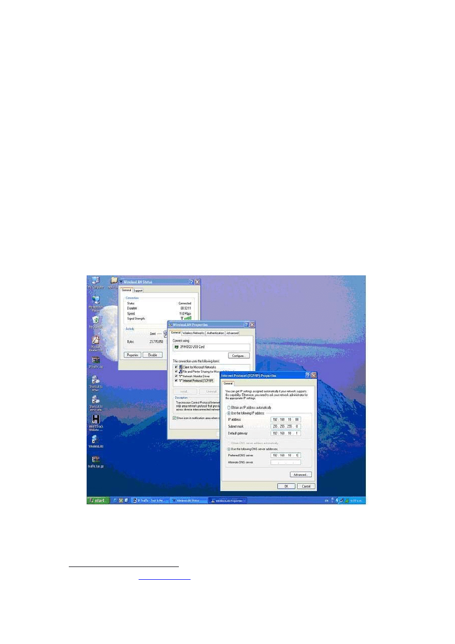
45
Appendix B
Configuration Procedure
The following describes the modification made to the wireless LAN architecture used in [5] in
order to enhance it to support multiple clients. Section 1 presents the enhancements made to
the clients side and Section 2 illustrates the modifications made to the server side.
B.1 The
Clients
side
After installing ORiNOCO Wireless LAN Gold Cards
32
on Windows XP client machines, the
client machines were assigned suitable IP addresses and subnet masks. The IP address of
gateway and DNS server on each machine was also specified (See Figure B-1).
Figure B-1: Specifying the IP addresses
The domain and computer name for each client was specified, as shown in Figure B-2.
32
Donated by Lucent (
www.lucent.com
)
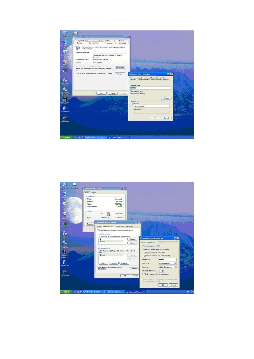
46
Figure B-2: Configuration of computer and domain name
Figure B-3 illustrates the specification of WEP authentication and encryption, using 45-bit
key length. WEP encryption was implemented at security layers 4, 5, 7 and 8.
Figure B-3: Configuration of WEP encryption
The IEEE 802.1x authentication protocol (EAP-TLS) was implemented at security layers 6, 7
and 8. Figure B-4 illustrates the process of specifying the properties for each digital certificate.
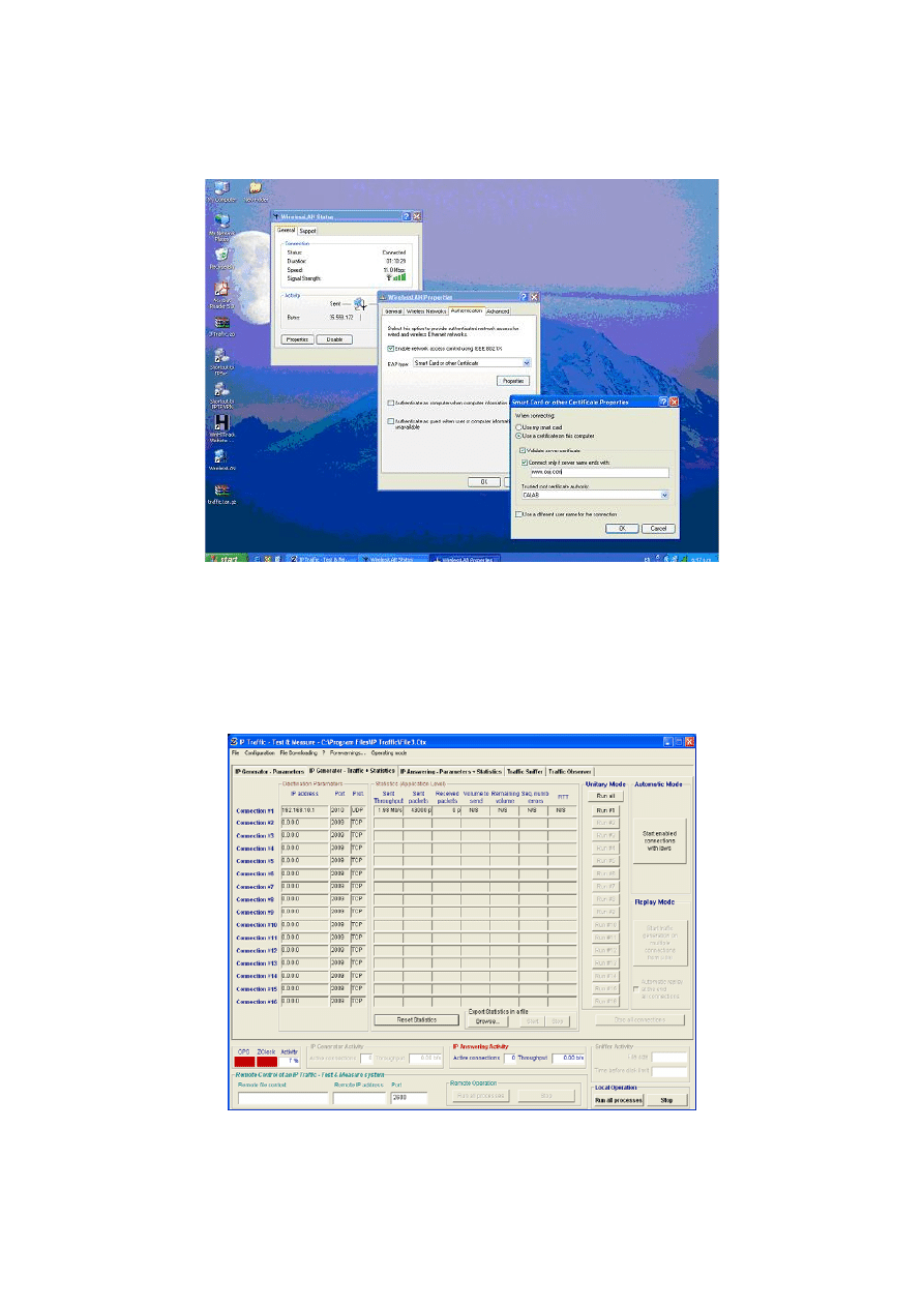
47
The certificates were issued by CALAB, the Certification Authority, which was set up on
server machine (See Figure B-12). The certificates were used for authenticating the users.
Figure B-4: Specifying the certificate properties
IP Traffic
IP Traffic, the traffic generator used in this research, has two operating modes. Figure B-5
shows the client mode.
Figure B-5: IP Traffic on Clients side
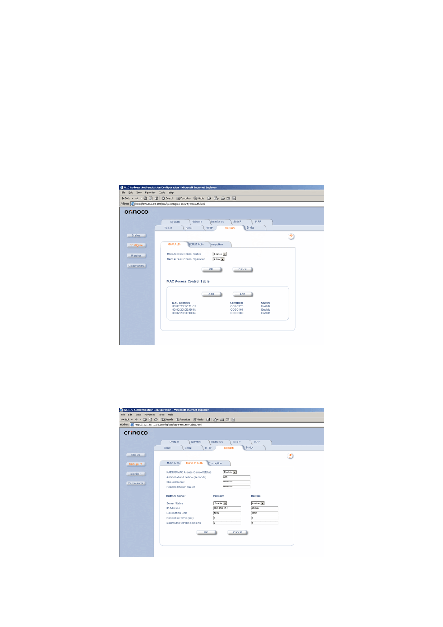
48
As described in Section 3.2.5 of the report, one active connection was used from each client
machine to send and receive traffic. The IP address of the server and type of traffic was also
specified.
B.2
The Server Side
Access Point configuration
Figure B-6 illustrates the MAC authentication tab on the AP. The IP addresses of new client
machines were added to MAC Access Control Table. The MAC authentication security was
in place from security layer 2 onwards.
Figure B-6: Implementing the MAC authentication
Figure B-7 shows the specification of RADIUS authentication on the AP. RADIUS
authentication was activated on AP at security layers 6, 7 and 8.
Figure B-7: Activating the Radius Server on the AP
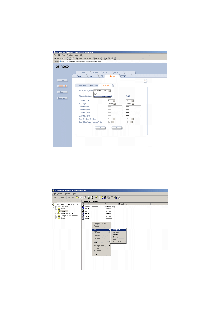
49
The IEEE 802.1x security was used in security layers 6, 7 and 8. Figure B-8 illustrates the
encryption key parameters specified on the AP. These parameters were the same as the ones
specified on the clients side (See Figure B-3).
Figure B-8: 802.1x security model on the AP
Server configuration
The new client machines and new users were added to the Active Directory (AD), as shown
in Figure B-9 and B-10.
Figure B-9: Adding new machines to AD
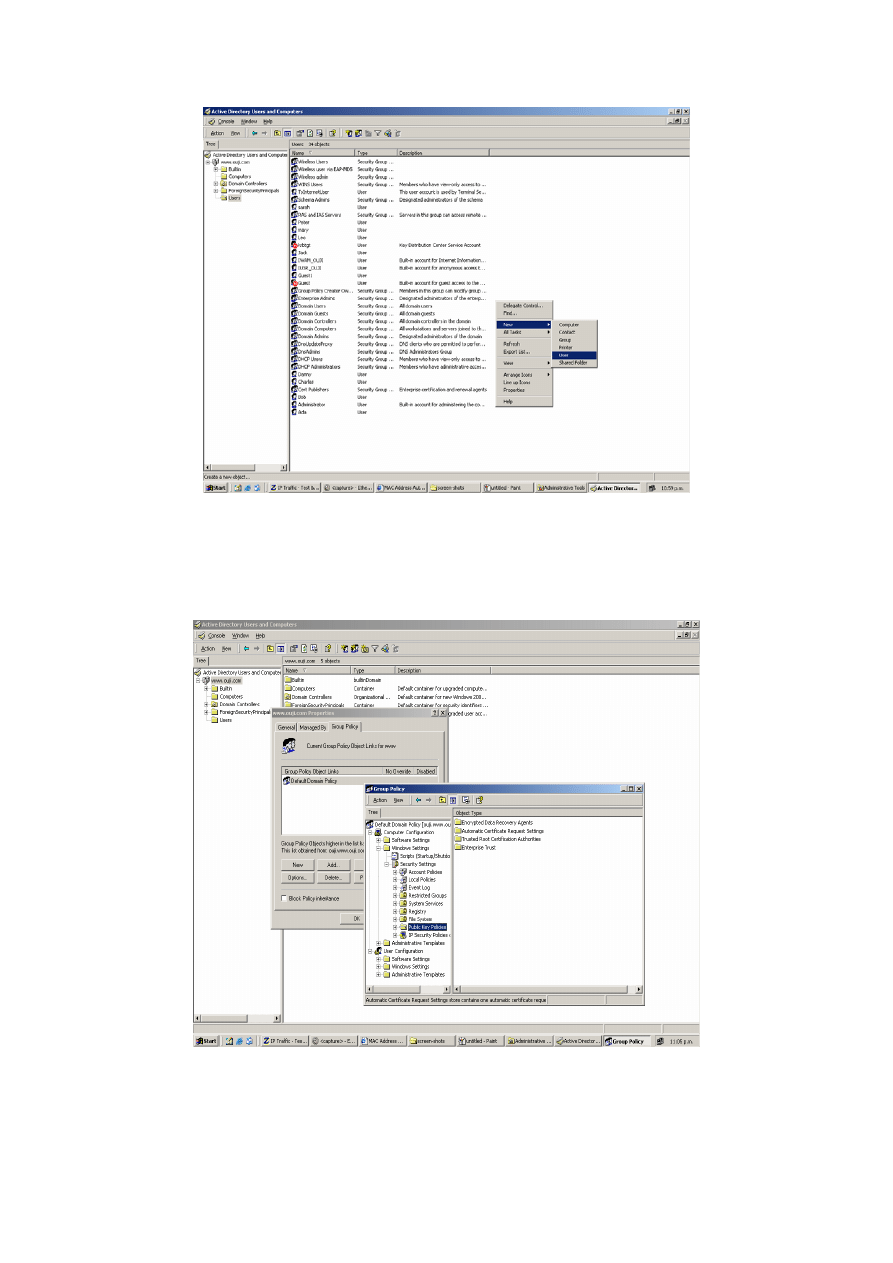
50
Figure B-10: Adding new users to AD
In the PKI configuration, the option for issuing automatic machine/computer certificates was
enabled, as shown in Figure B-11.
Figure B-11: Automatic issuing of computer certificate
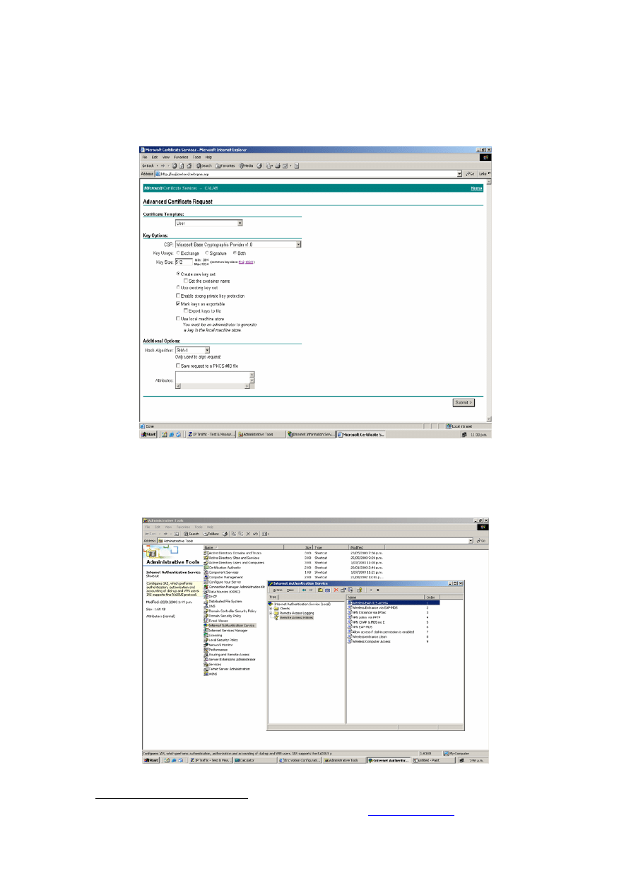
51
CALAB, the Microsoft certification authority, was used on the server side to issue certificate
to the users. Figure B-12 illustrates the parameters specified during the process of issuing
certificates. The certificates were stored on the server and were transferred to the client
machines. In doing that, it was important to mark the keys as exportable
33
.
Figure B-12: Issuing certificates to network users
Figure B-13 illustrates the process of specifying the security mechanism on the server side
(Remote Access Policy).
Figure B-13: Configuring the security mechanisms on server
33
In order to access the certification authority on the server, the
\\servername\certsrv
address was used.
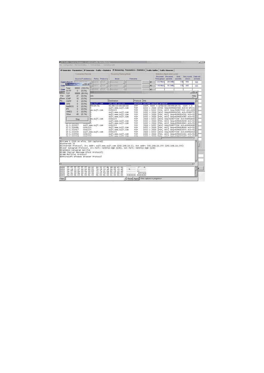
52
Ethereal
As described in section 3.2.2 of the report, Ethereal was used to capture the traffic generated
by IP Traffic tool between the server and the clients.
Figure B-14: Ethereal capturing TCP packets on server side
Figure B-14 illustrates the process of capturing TCP packets. The packets were then filtered
and protocol statistics were used in order to calculate the throughout and response times of the
network.
Wyszukiwarka
Podobne podstrony:
(Ebooks) Hacking Wireless Lan Security, What Hackers Know That You Dont
Lab 1 OPNET Analiza sieci standardu IEEE 802 11 hacked by reczu
802 11 Security
802 11 Bezpieczeństwo
IEEE 802 id 209525 Nieznany
4 2 4 5 Packet Tracer Connecting a Wired and Wireless LAN Instructions
802 11 Bezpieczenstwo
802 11 Bezpieczenstwo 802bez
802 11 Sieci bezprzewodowe Przewodnik encyklopedyczny
@802 11 sieci bezprzewodowe przewodnik encyklopedyczny FKBFG464DII2NQ2EJZ442DS352ES7GCDPJHZYBI
Sieci radiowe typu Wireless LAN, Szkoła, Systemy Operacyjnie i sieci komputerowe, sieci
Teoria Sieci Wireless LAN WiFi
Hardening IEEE802 11 Wireless Networks
IEEE 802 1X
802 11 Bezpieczenstwo 802bez id Nieznany
Instrukcja instalacji Adapter Wi Fi Ferguson USB W02 IEEE 802 11bgn 150Mbps
więcej podobnych podstron