
IPENZ Transactions, 1999, Vol. 26, No. 1/EMCh
7
Compliant blades for wind turbines
Andrew T Lee
1
, BE(Hons)
Richard G J Flay
2
, BE(Hons), PhD, MIMechE, (Fellow)
This paper details an aeroelastic study of compliant blades used in the passive power control of
horizontal-axis wind turbines. By designing the blades using fibre-reinforced composite materials,
coupling between bending and torsion can be incorporated. The present work investigates the
capability of a 50 kW constant speed wind turbine to automatically shed power in gusts by feather-
ing the blades, i.e. twisting them towards the relative wind vector thus reducing the angle of attack,
whilst bending away from the wind.
Although the design of compliant or flexible blades is rather more complex than rigid blades, it has
the advantage of reducing the aerodynamic loads at their source, and consequently this reduces the
loads which need to be carried by the power train and the tower. Wind turbine designers have
experienced some difficulty developing active controllers to pitch blades fast enough to control the
power generation, and so in windy gusty conditions such as in hilly New Zealand terrain, one would
expect the power output of fixed speed pitch controlled wind turbines to vary rather more than
desired. Compliant blades may offer a more effective means of power control, and of reducing
fatigue damage.
This numerical study demonstrated that it was difficult to achieve constant power output with com-
pliant blades for a fixed-speed wind turbine because a large amount of twist is required. When a
gust arrives at a blade the relative wind vector is rotated forwards, thus increasing the angle of
attack, and hence the lift coefficient. In order to reduce the power, the blade feather angle had to be
larger than this gust-induced increased angle of attack. This would typically be several degrees,
and meant that induced blade pitch angles need to be at least 15° to be effective.
Keywords: wind turbines - compliant blades - fibre-reinforced composites - aeodynamics
1
Postgraduate student and
2
Associate Professor, Department of Mechanical Engineering, Univer-
sity of Auckland, Private Bag 92-019, Auckland
After peer review, this paper, which was originally presented at the 1998 IPENZ Conference, was
received in revised form on 2 October 1998.
1.
Introduction
The development of wind turbines has made a significant
contribution to human achievement and technological
advancement throughout history. With an ever increas-
ing demand for limited energy resources, and global con-
cern about pollution and environmental damage arising
from fossil fuels, wind turbines may begin to assert an
ever increasing role during the next century and beyond.
Recent advances in technology and performance have re-
sulted in current wind turbine designs being increasingly
efficient, cost effective, and reliable. The popular size of
machines has moved from the small-medium range, 50–
100 kW, to much larger 200 kW to 1 MW systems. In the
period from the mid 1970s to the mid 1980s, the average
power (kWh) per swept area (m
2
) increased approximately
40% (Spera, 1994). The installed costs have decreased on
average by 83% since the mid 1970’s. Performance im-
provements can be expected in the future, especially in
the areas of blade construction and durability, control sys-
tems, materials and weight. A greater understanding of
the fatigue characteristics of blade materials and the ef-
fect of wind conditions such as turbulence on the rotor
and tower, will no doubt improve future designs.
New Zealand’s location across the prevailing westerly
winds associated with the ‘Roaring Forties’ provides a
plentiful wind resource. The current utilisation of this
resource is insignificant, with only a handful of machines
rated above 50 kW in operation throughout the country.
The recent installation of seven Enercon E-40 wind tur-
bines at the Hau Nui site near Wellington is the first com-
mercial wind farm in the country, with a rated output of
3.5 MW. Van Lieshout (1993) produced various cost es-
timates relating to the set-up of wind-farms in New Zea-
land. The initial capital cost would be in the region of
NZ$2,000/kW, and the operation and maintenance cost
between 2–5% of the capital cost per annum. The cost to
the consumer could be as low as 8c/kWh if sites with av-
erage wind-speeds 10–11 m/s are used, and the capacity
factor is up around the 35% mark. It was also suggested
that future costs could fall to as low as 5c/kWh for excep-
tional sites. Further information on the cost of wind farm
electricity can be found in Collecutt(1994) and Biggar
(1995).
A major problem influencing the design and operation of
wind turbines is fatigue. The lifetimes of most compo-
nents are gradually reduced by the high number of revo-
lutions that occur at relatively low stress magnitudes.
Turbine blades are the components which exhibit the larg-
est proportion of fatigue failure (50%), and the centrifu-
gal and gravity loads are primarily responsible (Eggleston
and Stoddard, 1987). Other contributions to fatigue dam-
age arise from, wind shear, turbulence, tower shadow and
interference from upwind turbines. The affect that each
8
The Institution of Professional Engineers New Zealand
of these factors has on the rotor is difficult to determine,
and much research is being conducted to gain an improved
understanding, such as the work described by Noda (1997).
2. Wind turbine design theory
The first and most fundamental aerodynamic model de-
veloped for horizontal axis wind turbines, was the actua-
tor disk theory proposed by Rankine in 1895. This highly
idealised model treats the turbine rotor as a non-rotating
homogeneous disc that removes energy available in the
wind, and converts it into useful mechanical energy. Us-
ing momentum theory, considering the pressure drop
across the actuator, and by applying Bernoulli’s equation
upstream and downstream of the disc it can be shown that
the maximum possible power coefficient C
p,max
is 0.593.
This value is called the Betz limit, and enables the maxi-
mum amount of power that a wind turbine can theoreti-
cally produce to be determined.
This idealised flow theorem was further developed by
Glauert [1935], who treated the rotor as a rotating actua-
tor disk, and summed individual effects through a number
of annulus stream-tubes. At this stage the effects of wake
rotation had also been incorporated into the analysis to
give a more accurate estimation of the power output.
Glauert’s optimum actuator disk theory prompted the con-
ception of Blade Element Theory, which further increased
accuracy by integrating all properties over radial incre-
ments of the blades.
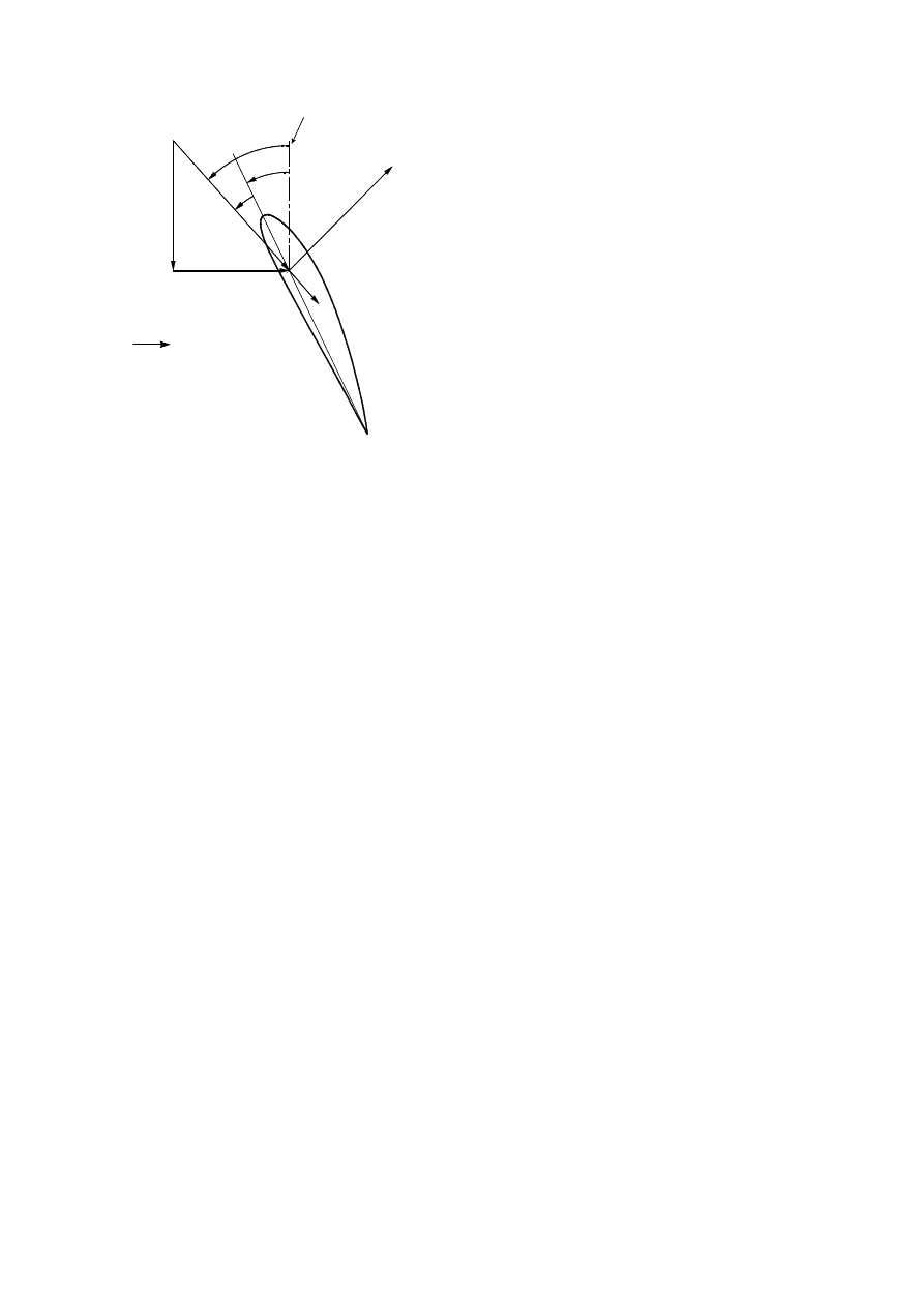
A section of a blade at radius r is illustrated in Fig. 1, with
the associated velocities, forces and angles shown. The
relative wind vector at radius r, denoted by W, is the re-
sultant of an axial component u
P
, and a rotational compo-
nent u
T
. The rotational component is the sum of the ve-
locity due to the blades motion,
r
Ω
, and the swirl veloc-
ity of the air,
r a
Ω ′
. The axial velocity u
P
, is reduced by a
component
V a
0
, due to the wake effect or retardation
imposed by the blades, where
V
0
is the upstream undis-
turbed wind speed. The
′
a
and
a
terms represent the ro-
tational and axial interference factors respectively. The
angle of attack is denoted by
a
, the pitch of the blade by
q
, and the angle of the relative wind to the plane of rota-
tion, by
f
. The resultant lift and drag forces are repre-
sented by L and D, and directed perpendicular and paral-
lel to the relative wind as shown.
Designing wind turbine blades using strip theory or re-
lated blade element theories requires knowledge of the
characteristics and behaviour of airfoil sections. This in-
formation is presented in the form of data which is usu-
ally obtained from wind tunnel tests on 2-D sections. In
the past, wind turbine designers have relied on airfoil sec-
tions and data intended for aircraft use. The NACA 230XX
series, NACA 44XX series, and the NACA 63-2XX series
airfoils are primarily for aircraft use, but have all been
used extensively in the design of HAWTs. The NACA
63-2XX series has since proven to provide the best over-
all performance, and are almost insensitive to surface foul-
ing. The increase in efficiency of modern wind turbine
blades is a direct result of independent research into new
sections specifically tailored for wind turbine blades. It
is important to remember that much of a turbine blade
operates in the stalled region where the angle of attack is
large, and low Reynolds number flows are experienced.
Aircraft wings typically operate at lower angles of attack,
and in extremely high Reynolds number flow regimes.
3. Composite material wind turbine blades
Modern wind turbine blades are commonly constructed
from some form of composite material. A composite
material is formed from two or more discrete component
materials, which in combined form posses different, ide-
ally improved properties than exhibited individually. The
most commonly used types of composite material in the
wind turbine industry are glass fibre-reinforced plastics
(GRP). GRP dominates the market because it provides
the necessary properties at a low cost. The important char-
acteristics of GRP are good mechanical properties, good
corrosion resistance, high temperature tolerance, ease of
manufacture, and favourable cost. More importantly, com-
posite materials enable structures to be designed to pro-
vide significant advantages such as weight reduction, over
traditional engineering materials, whilst maintaining the
required levels of performance and reliability.
By laying up the individual plies at certain orientations,
the laminates can be designed to provide the desired
strength and stiffness characteristics required for specific
applications. Furthermore, the material anisotropy ob-
served in some laminate configurations can be exploited
to induce coupling between different deformation modes.
For example, bend-twist coupling results in twisting of a
structure when a pure bending load is applied. Stretch-
ing-twisting coupling can occur when a tensile load is
applied, and the object deforms both axially and torsionally
about some reference axis. This behaviour is influenced
L
D
θ
φ
α
u
T
=r
Ω
(1+a’)
u
P
=V
0
(1-a)
plane of rotation
W
V
0
FIGURE 1. Blade element force velocity diagram.

IPENZ Transactions, 1999, Vol. 26, No. 1/EMCh
9
both by the material characteristics of the laminate and
geometric properties of the structure to which it is assigned.
Ironically, in the past these cross-coupling effects have
posed serious difficulties to designers, who have attempted
to eliminate these undesirable couplings from their mate-
rials. However, some industries are beginning to capital-
ise on these responses, such as the aeronautical commu-
nity, where the performance of wings may be improved
by the use of materials exhibiting bend-twist, and tension-
shear couplings. The use of fibre reinforced composite
blades enables a number of possible passive aerodynamic
control options to be investigated. The three options con-
sidered in this study rely on coupled deformation effects
of the composite materials to obtain the necessary twist
or pitch for power control.
Traditionally, the majority of composite material struc-
tures are constructed with symmetrical laminates. A sym-
metrical laminate is one that is mirrored about its mid-
plane. An important characteristic of all symmetric lami-
nates is that coupling between the membrane and bend-
ing modes is effectively zero. Fortunately symmetric lami-
nates are capable of inducing bend-twist coupled defor-
mation, whereas to utilise the tension-twist coupling ef-
fect, non-symmetric laminates must be used. Having to
consider the membrane-bending stiffness coupling terms
not only increases the complexity of the design process,
but also increases the risk of introducing effects that are
difficult for designers to detect and account for.
4. Wind turbine loads model and simulation
The development of software to calculate the loads on a
turbine blade and the overall performance was necessary
for the static and dynamic FEM modelling of the blades,
and aided the understanding of the theory and design
methodology. The analytical code and associated graphi-
cal user interface was developed using the mathematical
modelling package Matlab™, using its vast library of pre-
defined operations, and its flexible high level code. The
software, although crude, was intended to provide the
necessary data for the subsequent blade modelling in this
project, and not as a complete design or analysis package.
A number of forces and moments are experienced by a
typical HAWT blade during normal operation. The rela-
tive magnitudes of these loads, and the impact on the blades
make some more critical than others. The loads that were
identified as being the most significant for subsequent
analysis and design purposes in decreasing order of im-
portance for a small (50 kW) wind turbine were:
•
Aerodynamic forces and moments in both the
chordwise and flapwise directions.
•
Gravity force and moment in the chordwise, flapwise
and axial directions.
•
Centrifugal forces and moments in the flapwise and
axial directions.
•
Pitching moments about the aerodynamic centre due
to the lift force and the blade self weight.
The gyroscopic loads were ignored, based on the assump-
tion that the rotor yaw rate would be sufficiently low as to
cause negligible effects.
5. Requirements for passive power control
by coupled bend-twist blade pitch
Although passive power control of wind turbine rotors
achieved by exploiting the cross coupling characteristics
of anisotropic fibre reinforced composite materials has
exhibited some potential (Karaolis et al., 1991) the extent
of its effectiveness to actual designs requires further in-
vestigation. This section presents the required operating
conditions necessary for the successful application of a
blade feathering control method. These requirements are
illustrated by the analysis of a turbine rotor whose blades
are twisted by various amounts and then the power output
calculated for a range of wind speeds.
The specifications of the blade design used for this inves-
tigation are presented in Table 1. Rotor and generator
efficiencies were incorporated in the design so that the
applied loads reflected realistic rather than ideal values.
The generator and rotor were each assigned an efficiency
of 0.9, giving the turbine an overall efficiency of 0.81.
Therefore in order to generate 50 kW of useful power the
rotor must be directed to produce around 62 kW to allow
for the system loses.
TABLE 1. Specifications of base blade design.
Rated power:
50 kW
Rated wind speed:
12.0 m/s
Rotor diameter:
16.0 m
Profiled Blade length:7.0 m
Root chord:
0.8 m
Tip chord:
0.30 m
Root pitch angle: +14.0º
Tip pitch angle:
0º
Rotor speed:
62.0 RPM
Tip-speed ratio:
4.33
NACA airfoil:
4415
Average Reynolds no. 1.5 × 10
6
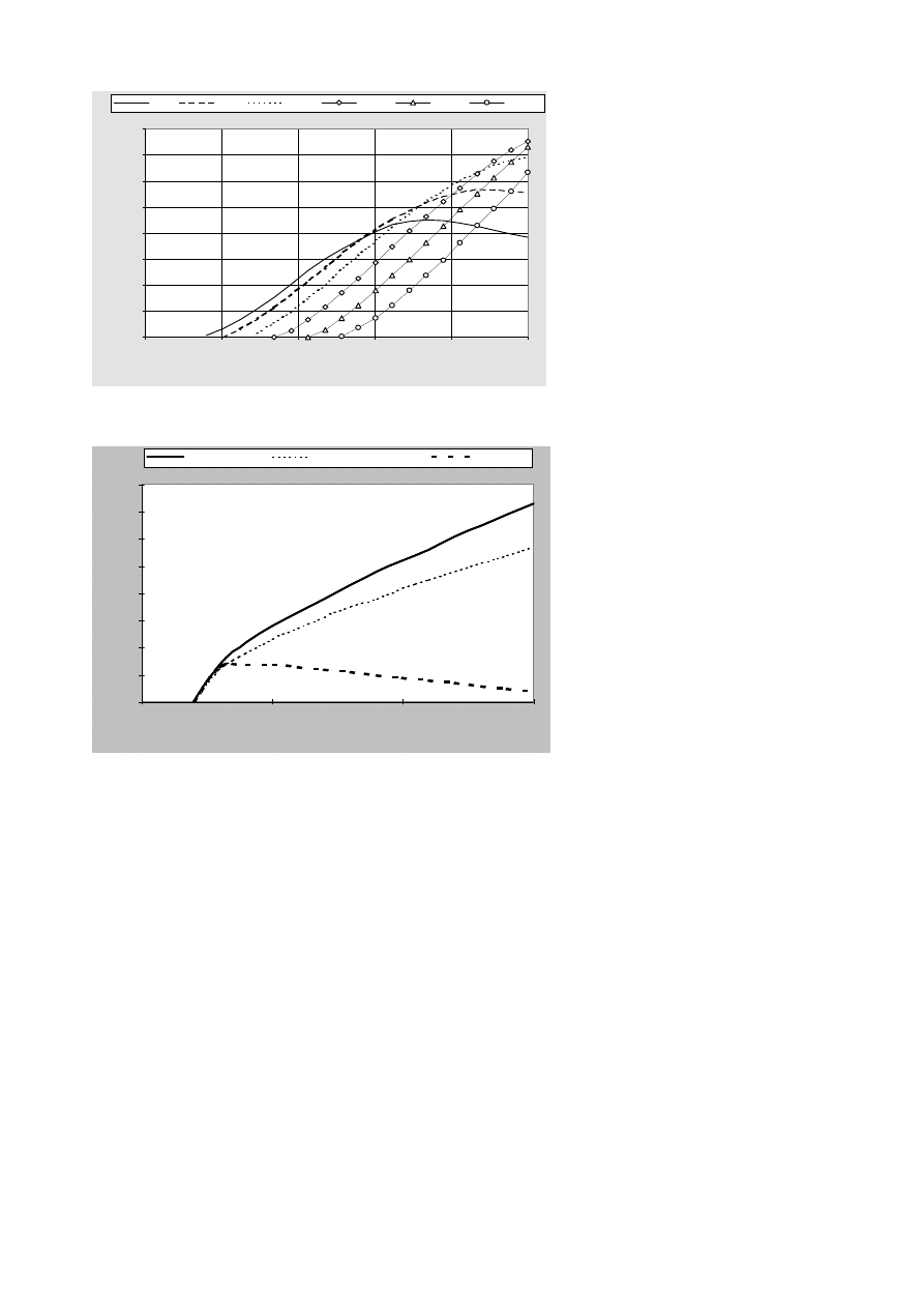
Figure 2 displays a family of power curves for the simu-
lation model 50 kW HAWT operating under ideal condi-
tions between cut-in and cut-out speeds. The solid curve
represents the response of fixed pitch blades (the base de-
sign). The other curves (e.g. the diamonds denoting –15
degrees of twist) have a linear twist distribution, 0 at the
root to the specified value at the tip, superimposed on the
base design twist distribution. The angle of attack is thus
reduced as the radius increases, simulating a possible feath-
ered blade twist distribution.
Using these data, a plot of the ideal twist distributions
required for above-rated wind speeds and constant power
output of this rotor, can be generated in terms of the nec-
essary tip pitch angle, as shown in Fig. 3. For example
the “passive feathering” line in Fig. 3 was generated by
reading off the wind speeds in Fig. 2 corresponding to the
fixed power of 50 kW for each of the twist angles. It is
obvious from Fig. 3 that large magnitudes of pitch are
required for successful feathering at the wind speeds above
rated.
For comparison the corresponding curve for pitch towards
stall is shown and indicates that significantly lower
magnitudes are required for above-rated wind speeds. The
pitch angle gradient for above-rated wind speeds is simi-
10
The Institution of Professional Engineers New Zealand
0
5
10
15
20
25
30
35
40
10
15
20
25
Win d s pe e d (m /s )
Pitch angle magnitude (deg)
Passive f eathering
A ctive f ull-span f eathering
Passive stall
0
20
40
60
80
100
120
140
160
0
5
10
15
20
25
Winds pe e d (m /s )
Aerodynamic Power (kW)
0 deg
-5 deg
-10 deg
-15 deg
-20 deg
-25 deg
FIGURE 3. Simulated pitch requirements for constant power output.
FIGURE 2. Ideal bend-twist pitch control simulation.
lar to feathering initially, but then changes sign resulting
in smaller angles as the wind speed increases. At the cut-
out speed of 25 m/s, the necessary pitch angle is only 2
degrees for the stall case, about 18 times less than the
feathering pitch magnitude. The large pitch magnitudes
required for feathering are characteristic of fixed speed
HAWTS such as the Vestas V27-225 kW machine which
is designed to vary the blade pitch angle up to 30 degrees
at the tip in order to maintain the rated power level
(Petersen, 1990).
The “active full-span feathering” line in Fig. 3 shows the
required twist angles when the whole blade is twisted
through the same angle. Thus the required angles are less
than for “passive feathering” line where the imposed twist
distribution is linear and the tip is twisted but the root is
not twisted at all.
6. Aeroelastic modelling of blades
Aeroelasticity refers to the response characteristics of a
flexible structure when coupled with aerodynamic load-
ing, and is primarily associated with the design and per-
formance optimisation of aircraft. The
term aeroelastic tailoring is commonly
used to describe the design and
optimisation process of structures that
are constructed of laminated composite
materials. These structures are used to
achieve aerodynamic performance ben-
efits by controlled structural deforma-
tion. The aeroelastic tailoring of wind
turbine blades using the cross-coupling
characteristics inherent in some lami-
nated composites relies on the structure
being both the control system sensor and
actuator. The response behaviour is
defined by the blade’s geometric struc-
ture and material properties. A finite
element method (FEM) approach was
used to model the aeroelastic behaviour
of a wind turbine blade, and this was
performed using the commercial pack-
ages Lusas, Patran and Nastran.
The main purpose of aeroelastic analy-
sis is to obtain information describing
the control, stability and strength char-
acteristics of a lifting body or structure.
Modelling the aeroelastic behaviour of
a wind turbine blade required a method
of coupling the aerodynamic load evalu-
ation system with the structural response
system. Such an analysis system is
diagramatically represented in Fig. 4.
It is generally accepted that higher mean
annual wind speeds are likely to be ex-
perienced at potential sites in New Zea-
land, than at most American or Euro-
pean sites. This claim is supported by a
study of the comparative operating con-
ditions for HAWT generators in New
Zealand and wind farms in Altamont Pass, California,
where a total capacity of almost 1700 MW has been in-
stalled since 1981. The annual mean wind speed was found
to be almost 4 m/s higher for the former (Van Lieshout,
1991) and as a result, most commercially available wind
turbines are not optimally suited for the more adverse and
seasonal New Zealand conditions. Research has shown
that the higher wind speeds are likely to inflict greater
magnitudes of fatigue damage per cycle, and therefore
turbine blades primarily designed for European and Ameri-
can conditions should exhibit shorter lifetimes (Noda,
1997).
The following points were considered during the design
process for flexible blades:
•
The high strength, low modulus properties of GRP
results in blades with higher thickness to chord ratios
than for other materials.
•
Thin-walled hollow sections are typically used to pro-
vide minimal weight blades for a given stiffness, but
foam cores or internal struts are usually necessary to
IPENZ Transactions, 1999, Vol. 26, No. 1/EMCh
11
prevent local buckling, especially for low stiffness
blades.
•
Skin fibre-reinforced composite laminates for conven-
tional stiff blades incorporate a combination of unidi-
rectional plies to support radial loads and provide suf-
ficient bending stiffness, and 45° plies to restrict shear
and torsion.
•
An iterative process is typically used to arrive at the
optimum ply stacking sequences that satisfy the de-
sired stiffness and strength requirements.
•
A current practice for composite wind turbine blade
design is to limit the axial strains in the skins to 0.002
or 0.2%. This figure corresponds to the conservative
value of the linear limit observed for typical glass re-
inforced polyester laminates (Mayer, 1996). The lin-
ear limit is defined as the point at which the stress-
strain values begin to fall significantly below the lin-
ear tensile modulus line.
The same rotor-blade aerodynamic design was
used for this analysis as for the study in Sec-
tion 5 (see Table 1). The rotor-blade design
was based on a rated power of 50 kW for the
HAWT. It was assumed that the site mean wind
speed was 8 m/s at a height of 10m, and the
rated wind speed was taken as 1.5 times
(Collecutt, 1994, Johnson 1985) the mean wind
speed, i.e. 12 m/s. The fixed rotational speed
was specified as 6.5 rad/s or 62.1 RPM.
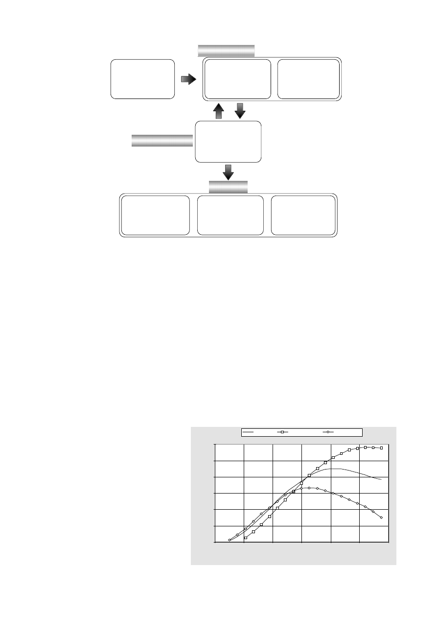
The line with squares in Fig. 5 displays the
power output curve for the composite rotor
blades. They have been designed with an op-
timum composite lay-up to achieve maximum
twist in the feather direction (to reduce the angle of attack
of the blades). The tip twist and average deflection for
this configuration were 4.8° and 0.42 m respectively.
Results for stiff (zero twist) blades are shown by the full
line. The effect of having the blades twist towards stall
(to increase the angle of attack) was also investigated by
simply reversing the sign of the twist obtained for the feath-
ered blades, and recalculating the power. Previous analy-
ses had shown that this approach for the stall calculation
would not introduce significant errors.
The results presented in Fig. 5 show that the sensitivity of
the turbine performance to relatively small magnitudes of
induced twist is significant. The effect of feathering is to
amplify the blade loads, and hence the power output, to
almost double the rated power at above rated speeds. Thus
reducing the blade angle of attack by a smaller amount
than that required would result in undesirable power surges
0
20
40
60
80
100
120
2
6
10
14
18
22
26
Winds pe e d (m /s )
Power (kW)
Rigid Blade
Feathering Tw ist
Stalling Tw ist
Wind Characteristics
•Average Wind
•Turbulence
•Wind Shear
•Wind Direction
Aerodynamic Loads
•Modified Blade Element
Theory
•Pressure simulation
Inertial Loads
•Centrifugal
•Gravity
Structural Model
Blade Characteristics
•Geometry
•Structure
•Materials
Response
Strength/Failure Criterion
•Fatigue
•Max. Stress/Strain
Performance
•Deflections
•Efficiency
•Cost per kW
•Operating life-time
Stability
•Flutter
•Divergence
Loading Model
FIGURE 4. Aeroelastic model analysis system.
Figure 5. Effect of blade twist on turbine performance.

12
The Institution of Professional Engineers New Zealand
during gusts or high wind speeds. This behaviour is po-
tentially unstable and analogous to torsional divergence
of aircraft wings where the more the wing twists the greater
the twisting moment becomes, twisting it even further.
The stall case behaves more ideally so that the power
reaches a limit close to the rated value, and continues to
gradually decrease as the wind speed increases. How-
ever, stall control using rigid bladed rotors is more effec-
tive because of the recovery and maintenance of the rated
power level after stalling.
7. Conclusions
The numerical analysis of the bend-twist material cross
coupling option indicated that for blade feathering, very
large angles of pitch are required. The required distribu-
tions increase non-linearly from the root to tip, with maxi-
mum values at the tip reaching angles between 30°–40°
for the simulation model.
A significantly lesser pitch demand is displayed by the
pitching to stall option, and the angles are more likely to
be achieved by the bend-twist configured blades. How-
ever unlike the feathering option the required pitch an-
gles decrease with increasing wind speed as the blade
becomes more stalled
To obtain the levels of bending deflection for power re-
duction requires blades that are as lightweight as possible
to minimise the restoring effect of the centrifugal loads.
The levels of axial strain experienced will be far greater
than the typical guidelines used in the design of GRP
blades, and are likely to exceed the elastic limit for GRP
The structural non-linear finite element analysis of rotat-
ing flexible blades was accomplished successfully using
the commercial F.E packages LUSAS and PATRAN/
NASTRAN. The convenience of using the commercial
packages is restricted by the limitations and inflexible
nature associated with the software. Steady state dynamic
analysis was performed using the 50 kW simulation model,
and the results obtained were very satisfactory.
The maximum twist rate obtained during the study was
for a hollow blade model. This rate was 1.25°/m length
based on a 0.136 m per metre flapwise deflection rate.
The levels of induced twist were insufficient for power
control by feathering, and the required levels of pitch are
not attained during high winds or gusts. However pitch-
ing to stall by passive means is likely to maintain the power
below the rated level at high wind speeds but decreases
the power to such low levels that the capacity factor for
the machine becomes too low to make it economical.
8. Acknowledgements
The authors gratefully acknowledge the Electricity Cor-
poration of New Zealand (ECNZ) for providing the fi-
nancial support for this research project. The assistance
of ECNZ’s Strategic Development Group Director, Dinesh
Chand with the project is also appreciated.
9. References
Biggar, K. (1995) The cost of wind farm electricity. Energy
Impacts Unit, Ministry of Commerce, PO Box 1473, Wel-
lington, New Zealand.
Collecutt, G.R. (1994) The Economic Optimisation of Horizon-
tal Axis Wind Turbine Design Parameters. ME Thesis, Uni-
versity of Auckland.
Eggleston, D.M. and Stoddard, F.S. (1987) Wind Turbine Engi-
neering Design. Van Nostrand Reinhold, New York, p. 307.
Jensen, D.W. and Laglace, P.A. (1988) Influence of Mechanical
Couplings on the Buckling and Postbuckling of Anisotropic
Plates. AIAA Journal. 26: 1269–1277.
Johnson, G.L. (1985) Wind Energy Systems. Prentice-Hall, New
Jersey. pp. 147–149.
Karaolis, N.M., Musgrove, P.J. and Jeronimidis, G. (1991) Power
control of wind turbine blades through structural design.
Smart Structures and Materials. ASME, New York. vol. 24,
pp. 189–202.
Mayer, R.M. (1996) Design of Composite Structures Against
Fatigue, Applications to Wind Turbine Blades. Mechanical
Engineering Publications Ltd, UK, p. 36.
Noda, M. (1997) Development of a Fatigue Simulation Pro-
gram for Wind Turbines. ME Thesis, University of Auck-
land.
Petersen, S.M. (1990) Wind Turbine Test-Vestas V27-225 kW.
Riso Report M-2861, Riso National Laboratory, DK-4000
Roskilde, Denmark, p. 9.
Spera, D.A. (1994) Wind Turbine Technology: Fundamental
Concepts of Wind Turbine Engineering. ASME, New York,
p. 133.
Van Lieshout, P. (1993) Renewable Energy Opportunities for
New Zealand: Executive Report. Energy Efficiency and
Conservation Authority and Centre for Advanced Engineer-
ing, Christchurch, pp. 3.1-3.20.
Van Lieshout, P. (1991) Comparisons of Operational Conditions
of Wind Turbine Generators in New Zealand and Abroad.
DesignPower Report. Wellington, New Zealand, p. 1.
Wyszukiwarka
Podobne podstrony:
Wind Turbine 5 Metre Diameter Carbon Fibre Blades For Wind Turbine10Kwblades
Blade sections for wind turbine and tidal current turbine applications—current status and future cha
A Low Speed, High Torque, Direct Drive Permanent Magnet Generator For Wind Turbines
(Wind) A Low Speed, High Torque, Direct Drive Permanent Magnet Generator For Wind Turbines
Design Of Direct Driven Permanent Magnet Generators For Wind Turbines
0 Power Control for Wind Turbines in Weak Grids H Bindner 1999
Adjustable Speed Generators For Wind Turbines Based On Doubly
The Material Selection for Typical Wind Turbine Blades 2006
Innovative Solutions In Power Electronics For Variable Speed Wind Turbines
Modeling Of The Wind Turbine With A Doubly Fed Induction Generator For Grid Integration Studies
Development of wind turbine control algorithms for industrial use
Advanced Methods for Development of Wind turbine models for control designe
Boost Converter Design For 20Kw Wind Turbine Generator
0 Alternative Composite Materials for Megawatt Scale Wind Turbines Griffin Ashwill 2003
Development Of A Single Phase Inverter For Small Wind Turbine
więcej podobnych podstron