1 - 4
CCNA 2: Routers and Routing Basics v 3.0 - Lab 11.2.1b
Copyright
2003, Cisco Systems, Inc.
Lab 11.2.1b Standard ACLs
Objective
Plan, configure, and apply a standard ACL to permit or deny specific traffic and test the ACL to
determine if the desired results were achieved.
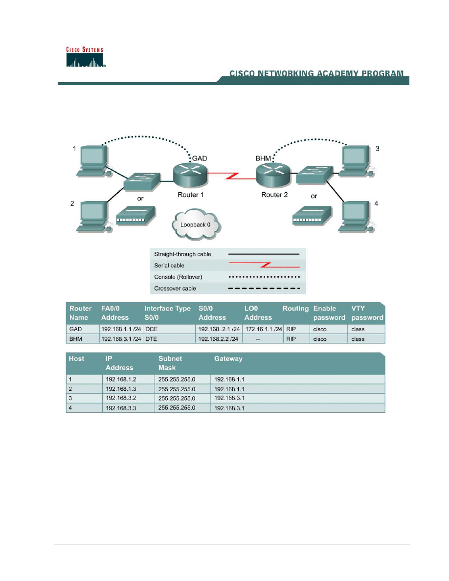
Scenario
The company home office in Gadsden (GAD) provides services to branch offices such as the
Birmingham (BHM) office. These offices have some minor security and performance concerns.
Standard ACL need to be implemented as a simple and effective tool to control traffic

2 - 4
CCNA 2: Routers and Routing Basics v 3.0 - Lab 11.2.1b
Copyright
2003, Cisco Systems, Inc.
Infrastructure
Host #3 represents the kiosk station that needs to have its access limited to the local network.
Host #4 represents another host in the Birmingham office Loopback 0 on the GAD router represents
the Internet.
Step 1 Basic Router Interconnection
a. Interconnect the routers as shown in the diagram.
Step 2 Basic Configuration
a. The router may contain configurations from a previous use. For this reason, erase the startup
configuration and reload the router to remove any residual configurations. Using the information
previously in the tables, setup the router and host configurations and verify reachablilty by
pinging all systems and routers from each system.
b. To simulate the Internet, add the following configuration to the GAD router.
GAD(config)#interface loopback0
GAD(config-if)#address 172.16.1.1 255.255.255.0
GAD(config-if)#exit
GAD(config)#router rip
GAD(config-router)#network 172.16.0.0
GAD(config-if)#^z
Step 3 Establish Access List Requirements
a. The kiosk station (host 3) needs to have its access limited to the local network. It is determined
that a standard access list needs to be created to prevent traffic from this host from reaching any
other networks. The access control list should block traffic from this host and not affect other
traffic from this network. Using a standard IP ACL is adequate for as it filters based on the
source address to any destination.
What source address of the kiosk? ____________________________
Step 4 Plan the Access List Requirements
a. As with any project, the most important part of the process is the planning. First, the information
needed to create the ACL need to be defined. An access list is made up a series of ACL
statements. Each of these statements adds sequentially to the ACL. Since the list will consist of
more than one statement, the order of the statement needs to be planned carefully.
b. It has been determined that for this ACL will require 2 logical steps. Each of these steps can be
accomplished with one statement each. As a planning tool, a text editor like Notepad can be
used to organize the logic and then write the list. In the text editor enter the logic by typing:
! stop traffic from host 3
! permit all other traffic
3 - 4
CCNA 2: Routers and Routing Basics v 3.0 - Lab 11.2.1b
Copyright
2003, Cisco Systems, Inc.
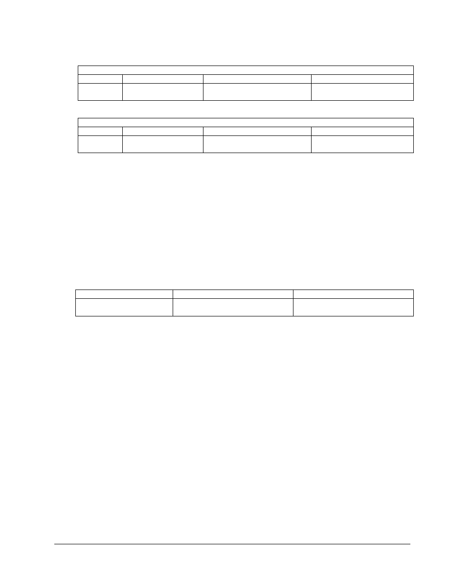
c. From this logic the actual ACL will be written. Using the tables below, document the information
for each statement.
stop traffic from host 3
List #
permit or deny
Source address
Wildcard mask
permit all other traffic
List #
permit or deny
Source address
Wildcard mask
d. What would be the result of not including a statement at to permit all other source addresses?
_________________________________________________________________________________________
e. What would be the result of reversing the order of the 2 statements in the list?
_________________________________________________________________________________________
f. Why are both statements using the same ACL number?
_________________________________________________________________________________________
g. The final step in the planning process is to determine the best location for the access list and the
direction the list should be applied. Examine the internetwork diagram and choose the
appropriate interface and direction. Document this in the table below:
Router Interface
Direction
Step 5 Write and Apply the ACL
a. Using the previously constructed logic and information of the access list, complete the
commands in the text editor. The list syntax should look similar to:
! stop traffic from host 3
access-list
#deny address wildcard
! permit all other traffic
access-list #permit address wildcard
b. Add to this text file the configuration statements to apply the list.
The configuration statements take the form of:
interface
type #/#
ip access-group
#{in, out}

4 - 4
CCNA 2: Routers and Routing Basics v 3.0 - Lab 11.2.1b
Copyright
2003, Cisco Systems, Inc.
c. Now the text file configuration needs to be applied to the router. Enter the configuration mode on
the appropriate router and copy and paste the configuration. Observe the CLI display to ensure
no errors were encountered.
Step 6 Verify the ACL
Now that the ACL is completed, the ACL needs to be confirmed and tested.
a. First step is to check the list to see if it was configured properly in the router. To check the ACL
logic use the show access-list command. Record the output
_________________________________________________________________________________________
_________________________________________________________________________________________
_________________________________________________________________________________________
b. Next, verify that the access list was applied to the proper interface and in the correct direction.
To do this examine the interface with the show ip interface command. Look at the output
from each interface and record the lists applied to the interface.
Interface ________________________________________________________________
Outgoing access list is ____________________________________________________
Inbound access list is ____________________________________________________
c. Finally, test the functionality of the ACL by trying to send packets from the source host and verify
that is to be permitted or denied as appropriate. In this case, ping will be used to test this.
[ ] verify that host 3 CAN ping host 4
[ ] verify that host 3 CANNOT ping host 1
[ ] verify that host 3 CANNOT ping host 2
[ ] verify that host 3 CANNOT ping GAD Fa0/0
[ ] verify that host 3 CANNOT ping GAD LO0
[ ] verify that host 4 CAN ping host 1
[ ] verify that host 4 CAN ping host 2
[ ] verify that host 4 CAN ping GAD Fa0/0
[ ] verify that host 4 CAN ping GAD LO0
Step 7 Document the ACL
a. As a part of all network management, documentation needs to be created. Using the text file
created for the configuration, add additional comments. This file should also contain output from
the show access-list and the show ip interface commands.
b. The file should be saved with other network documentation. The file naming convention should
reflect the function of the file and the date of implementation.
c. That should complete the ACL project.
d. Once finished, erase the start-up configuration on routers, remove and store the cables and
adapter. Also logoff and turn the router off.
Wyszukiwarka
Podobne podstrony:
CCNA2 lab 11 2 1b pl
IE RS lab 11 solutions
lab 11 4 5
Lab 11
lab 11 7 2
lab 11 2 3a
CCNA1 lab 11 2 4 pl
CCNA2 lab 11 2 3b pl
CCNA2 lab 11 2 2b pl
lab 11 3 3
lab 11 1 5 1
Lab 11 - Oznaczenie modułu jednostronnego ściskania skał, skaly11, WYDZIAŁ GÓRNICZY
lab 11 2 3c
Lab 11 - Oznaczenie modułu jednostronnego ściskania skał, jed.ścisk.11, Nr ?wiczenia_
Lab.11, lab2 pierwszastrona, I TD
więcej podobnych podstron