TL/H/5614
IC
Zener
Eases
Reference
Design
AN-173
National Semiconductor
Application Note 173
November 1976
IC Zener Eases Reference
Design
DESCRIPTION
A new IC zener with low dynamic impedance and wide oper-
ating current range significantly simplifies reference or regu-
lator circuit design. The low dynamic impedance provides
better regulation against operating current changes, easing
the requirements of the biasing supply. Further, the temper-
ature coefficient is independent of operating current, so that
the LM129 can be used at any convenient current level.
Other characteristics such as temperature coefficient, noise
and long term stability are equal to or better than good qual-
ity discrete zeners.
The LM129 uses a new subsurface breakdown IC zener
combined with a buffer circuit to lower dynamic impedance.
The new subsurface zener has low noise and excellent long
term stability since the breakdown is in the bulk of the sili-
con. Circuitry around the zener supplies internal biasing cur-
rents and buffers external current changes from the zener.
The overall breakdown is about 6.9V with devices selected
for temperature coefficients.
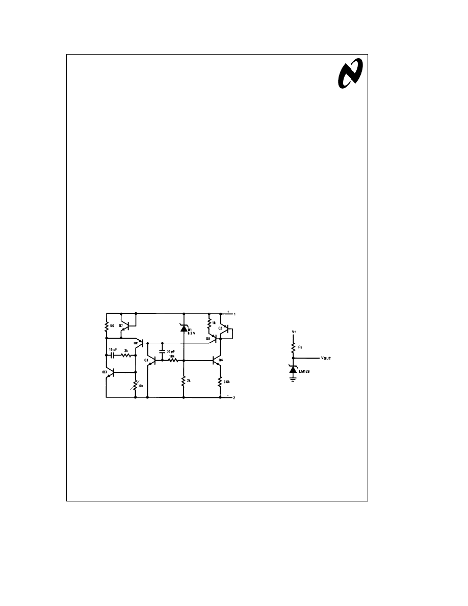
The zener is relatively straightforward. A buried zener D1
breaks down biasing the base of transistor Q1. Transistor
Q1 drives two buffers Q2 and Q3. External current changes
through the circuit are fully absorbed by the buffer transis-
tors rather than by D1. Current through D1 is held constant
at 250 mA by a 2k resistor across the emitter base of Q1
while the emitter-base voltage of Q1 nominally temperature
compensates the reference voltage.
The other components, Q4, Q5 and Q6, set the operating
current of Q1. Frequency compensation is accomplished
with two junction capacitors.
All that is needed for biasing in most applications is a resis-
tor as shown in
Figure 2 . Biasing current can be anywhere
from 0.6 mA to 15 mA with little change in performance.
Optimally, however, the biasing current should be as low as
possible for the best regulation. The dynamic impedance of
the LM129 is about 1 X and is independent of current.
Therefore, the regulation of the LM129 against voltage
changes is 1/Rs.
Lower currents or higher Rs give better regulation. For ex-
ample, with a 15V supply and 1 mA operating current, the
reference change for a 10% change in the 15V supply is
180 mV. If the LM129 is run at 5 mA, the change is 900 mV
or 5 times worse. By comparison, a standard IN821 zener
will change about 17 mV. All discrete zeners have about the
same regulation since their dynamic impedance is inversely
proportional to operating current.
If the zener does not have to be grounded, a bridge com-
pensating circuit can be used to get virtually perfect regula-
tion, as shown in
Figure 3 . A small compensating voltage is
generated across R1, which matches the dynamic imped-
ance of the LM129. Since the dynamic impedance of the
LM129 is linear with current, this circuit will work even with
large changes in the unregulated input voltage.
TL/H/5614 – 1
FIGURE 1. IC Reference Zener
FIGURE 2. Basic Biasing
C1995 National Semiconductor Corporation
RRD-B30M115/Printed in U. S. A.
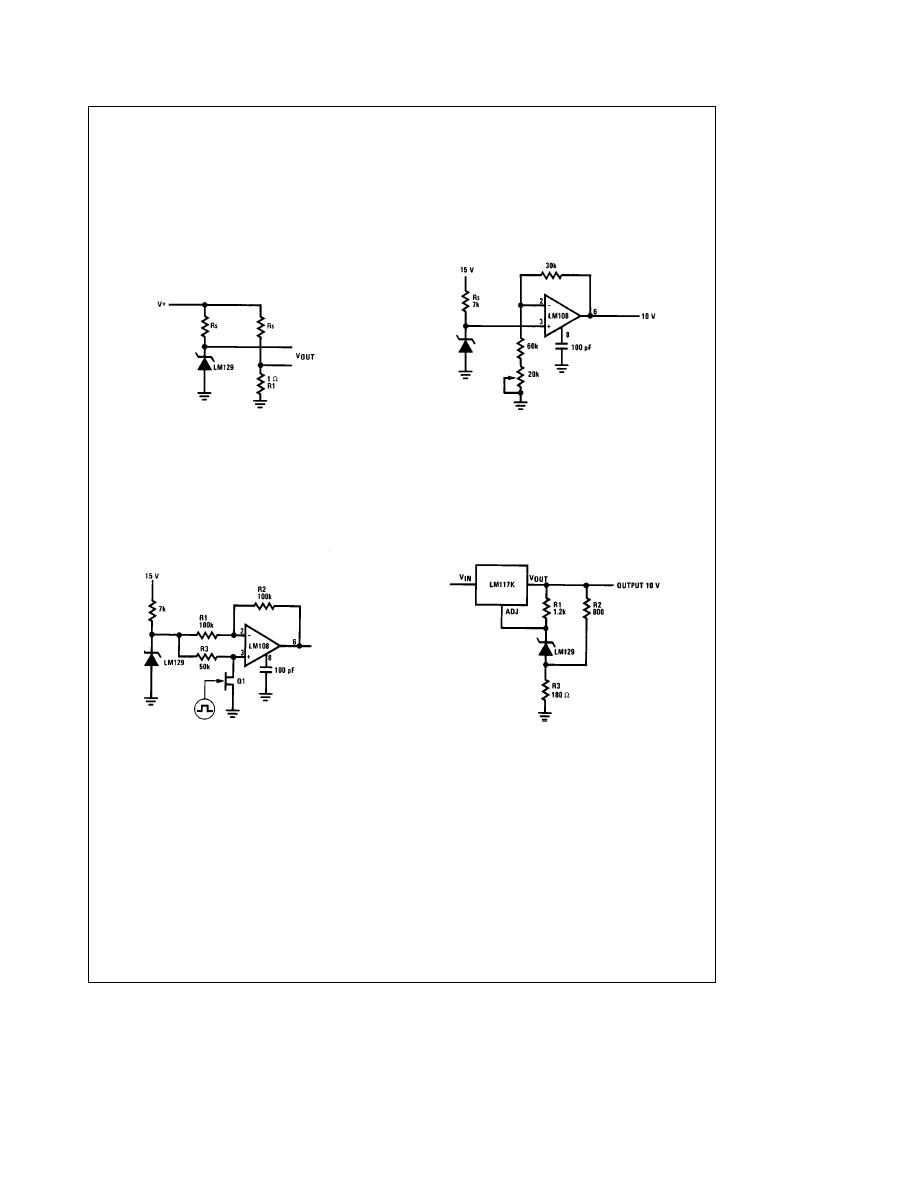
Other output voltages are easily obtained with the simple
op-amp circuit shown in
Figure 4 . A simple non-inverting
amplifier is used to boost and buffer the zener to 10V. The
reference is run directly from the input power rather than the
output of the op-amp. When the zener is powered from the
op-amp, special starting circuitry is sometimes necessary to
insure the output comes up in the right polarity. For outputs
lower than the breakdown of the LM129 a divider can be
connected across the zener to drive the op-amp.
An AC square wave or bipolarity output reference can easily
be made with an op-amp and FET switch as shown in
Figure
5 . When Q1 is ‘‘ON’’, the LM108 functions as a normal in-
verting op-amp with a gain of
b
1 and an output of
b
6.9V.
With Q1 ‘‘OFF’’ the op-amp acts as a giving 6.9 V at the
output. Some non-symmetry will occur from loading change
on the LM129 in the different states and mismatch of R1
and R2. Trimming either R1 or R2 can make the output
exactly symmetrical around ground.
FIGURE 3. Bridge Compensation for Line Changes
FIGURE 4. 10 Volt Buffered Output Reference
TL/H/5614 – 2
FIGURE 5. Bipolar Output Reference
FIGURE 6. High Stability 10 V Regulator
2
By combining the LM129 with an LM117 three-terminal reg-
ulator a high stability power regulator can be made. This is
shown in
Figure 6 . Resistor R1 biases the LM129 at about 1
mA from the 1.25V reference in the LM117. The voltage of
the LM129 is added to the 1.25V of the LM117 to make a
total reference voltage of 8.1V. The output voltage is then
set at 10V by R2 and R3. Since the internal reference of the
LM117 contributes only about 20% of the total reference
voltage, regulation and drift are essentially those of the ex-
ternal zener. The regulator has 0.2% load and line regula-
tion and if a low drift zener such as the LM129A is used
overall temperature coefficient is less than 0.002%/
§
C.
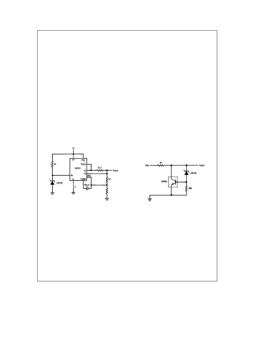
The new zener can be used as the reference for conven-
tional IC voltage regulators for enhanced performance.
Noise is lower, time stability is better, and temperature coef-
ficient can be better depending on the device selected. Fur-
ther, the output voltage is independent of power changes in
the regulator.
Figure 7 shows an LM723 using an external LM129 refer-
ence. The internal 7V reference is not used and a single
resistor biases the LM129 as the reference. The 5k resistor
chosen provides sufficient operating current for the zener
over the 10V to 40V input voltage range of the LM723.
Since the dynamic impedance of the LM129 is so low, the
reference regulation against line changes is only 0.02%/V.
This is small compared to the regulation of 0.1%/V for the
LM723; however, the resistor can be replaced by a 1 mA to
5 mA FET used as a constant current source for improved
regulation. When the FET is used reference regulation is
easily 0.001%/V. Output voltage is set in the standard man-
ner except that for low output voltages sufficient current
must be run through the zener to power the voltage divider
supplying the reference to the LM723.
An overload protected power shunt regulator is shown in
Figure 8 . The output voltage is about 7.8V
b
the 7V break-
down of the LM129 plus the 0.8V emitter-base voltage of
the LM395. The LM395 is an IC, 1.5 A power transistor with
complete overload protection on the chip. Included on the
chip are current limiting and thermal limiting, making the de-
vice virtually blowout-proof. Further, the base current is only
5 mA, making it easy to drive as a shunt regulator. As the
input voltage rises, more drive is applied to the base of the
LM395, turning it on harder and dropping more voltage ac-
cross the series resistance. Should the input voltage rise
too high, the LM395 will current limit or thermal limit, pro-
tecting itself.
The new IC zener can replace existing zeners in just about
any application with improved performance and simpler ex-
ternal circuitry. As with any zener reference, devices are
selected for temperature coefficient and operating tempera-
ture range. Since the devices are made by a standard inte-
grated circuit process, cost is low and good reproducibility is
obtained in volume production.
Finally, since the device is actually an IC, it is packaged in a
rugged TO-46 metal can package or a 3-lead plastic transis-
tor package.
TL/H/5614 – 3
FIGURE 7. External Reference For IC
FIGURE 8. Power Shunt Regulator
3
AN-173
IC
Zener
Eases
Reference
Design
LIFE SUPPORT POLICY
NATIONAL’S PRODUCTS ARE NOT AUTHORIZED FOR USE AS CRITICAL COMPONENTS IN LIFE SUPPORT
DEVICES OR SYSTEMS WITHOUT THE EXPRESS WRITTEN APPROVAL OF THE PRESIDENT OF NATIONAL
SEMICONDUCTOR CORPORATION. As used herein:
1. Life support devices or systems are devices or
2. A critical component is any component of a life
systems which, (a) are intended for surgical implant
support device or system whose failure to perform can
into the body, or (b) support or sustain life, and whose
be reasonably expected to cause the failure of the life
failure to perform, when properly used in accordance
support device or system, or to affect its safety or
with instructions for use provided in the labeling, can
effectiveness.
be reasonably expected to result in a significant injury
to the user.
National Semiconductor
National Semiconductor
National Semiconductor
National Semiconductor
Corporation
Europe
Hong Kong Ltd.
Japan Ltd.
1111 West Bardin Road
Fax: (a49) 0-180-530 85 86
13th Floor, Straight Block,
Tel: 81-043-299-2309
Arlington, TX 76017
Email: cnjwge
@
tevm2.nsc.com
Ocean Centre, 5 Canton Rd.
Fax: 81-043-299-2408
Tel: 1(800) 272-9959
Deutsch Tel: (a49) 0-180-530 85 85
Tsimshatsui, Kowloon
Fax: 1(800) 737-7018
English
Tel: (a49) 0-180-532 78 32
Hong Kong
Fran
3ais Tel: (a49) 0-180-532 93 58
Tel: (852) 2737-1600
Italiano
Tel: (a49) 0-180-534 16 80
Fax: (852) 2736-9960
National does not assume any responsibility for use of any circuitry described, no circuit patent licenses are implied and National reserves the right at any time without notice to change said circuitry and specifications.
Wyszukiwarka
Podobne podstrony:
finanse publiczne Podatki (173 okna)
Wykład 5 An wsk cz II
Mazowieckie Studia Humanistyczne r1996 t2 n1 s165 173
An%20Analysis%20of%20the%20Data%20Obtained%20from%20Ventilat
NLP for Beginners An Idiot Proof Guide to Neuro Linguistic Programming
02 01 11 11 01 44 an kol2 1 7id 3881
50 Common Birds An Illistrated Guide to 50 of the Most Common North American Birds
Intellivox AN Evac
173 Kair
(1 1)Fully Digital, Vector Controlled Pwm Vsi Fed Ac Drives With An Inverter Dead Time Compensation
Interruption of the blood supply of femoral head an experimental study on the pathogenesis of Legg C
an 04 2012
Intellivox AN Speech
Zizek, Slavoj Looking Awry An Introduction to Jacques Lacan through Popular Culture
an 11 2011
How to make an inexpensive exte Nieznany
Analysis of soil fertility and its anomalies using an objective model
więcej podobnych podstron